US6415034B1 - Earphone unit and a terminal device - Google Patents
Earphone unit and a terminal deviceDownload PDFInfo
- Publication number
- US6415034B1 US6415034B1US08/906,371US90637197AUS6415034B1US 6415034 B1US6415034 B1US 6415034B1US 90637197 AUS90637197 AUS 90637197AUS 6415034 B1US6415034 B1US 6415034B1
- Authority
- US
- United States
- Prior art keywords
- signal
- speech
- sound
- ear
- earphone unit
- Prior art date
- Legal status (The legal status is an assumption and is not a legal conclusion. Google has not performed a legal analysis and makes no representation as to the accuracy of the status listed.)
- Expired - Lifetime
Links
Images


Classifications
- H—ELECTRICITY
- H04—ELECTRIC COMMUNICATION TECHNIQUE
- H04R—LOUDSPEAKERS, MICROPHONES, GRAMOPHONE PICK-UPS OR LIKE ACOUSTIC ELECTROMECHANICAL TRANSDUCERS; DEAF-AID SETS; PUBLIC ADDRESS SYSTEMS
- H04R1/00—Details of transducers, loudspeakers or microphones
- H04R1/10—Earpieces; Attachments therefor ; Earphones; Monophonic headphones
- H04R1/1083—Reduction of ambient noise
- G—PHYSICS
- G10—MUSICAL INSTRUMENTS; ACOUSTICS
- G10K—SOUND-PRODUCING DEVICES; METHODS OR DEVICES FOR PROTECTING AGAINST, OR FOR DAMPING, NOISE OR OTHER ACOUSTIC WAVES IN GENERAL; ACOUSTICS NOT OTHERWISE PROVIDED FOR
- G10K11/00—Methods or devices for transmitting, conducting or directing sound in general; Methods or devices for protecting against, or for damping, noise or other acoustic waves in general
- G10K11/16—Methods or devices for protecting against, or for damping, noise or other acoustic waves in general
- G10K11/175—Methods or devices for protecting against, or for damping, noise or other acoustic waves in general using interference effects; Masking sound
- G10K11/178—Methods or devices for protecting against, or for damping, noise or other acoustic waves in general using interference effects; Masking sound by electro-acoustically regenerating the original acoustic waves in anti-phase
- G10K11/1781—Methods or devices for protecting against, or for damping, noise or other acoustic waves in general using interference effects; Masking sound by electro-acoustically regenerating the original acoustic waves in anti-phase characterised by the analysis of input or output signals, e.g. frequency range, modes, transfer functions
- G10K11/17813—Methods or devices for protecting against, or for damping, noise or other acoustic waves in general using interference effects; Masking sound by electro-acoustically regenerating the original acoustic waves in anti-phase characterised by the analysis of input or output signals, e.g. frequency range, modes, transfer functions characterised by the analysis of the acoustic paths, e.g. estimating, calibrating or testing of transfer functions or cross-terms
- G10K11/17815—Methods or devices for protecting against, or for damping, noise or other acoustic waves in general using interference effects; Masking sound by electro-acoustically regenerating the original acoustic waves in anti-phase characterised by the analysis of input or output signals, e.g. frequency range, modes, transfer functions characterised by the analysis of the acoustic paths, e.g. estimating, calibrating or testing of transfer functions or cross-terms between the reference signals and the error signals, i.e. primary path
- G—PHYSICS
- G10—MUSICAL INSTRUMENTS; ACOUSTICS
- G10K—SOUND-PRODUCING DEVICES; METHODS OR DEVICES FOR PROTECTING AGAINST, OR FOR DAMPING, NOISE OR OTHER ACOUSTIC WAVES IN GENERAL; ACOUSTICS NOT OTHERWISE PROVIDED FOR
- G10K11/00—Methods or devices for transmitting, conducting or directing sound in general; Methods or devices for protecting against, or for damping, noise or other acoustic waves in general
- G10K11/16—Methods or devices for protecting against, or for damping, noise or other acoustic waves in general
- G10K11/175—Methods or devices for protecting against, or for damping, noise or other acoustic waves in general using interference effects; Masking sound
- G10K11/178—Methods or devices for protecting against, or for damping, noise or other acoustic waves in general using interference effects; Masking sound by electro-acoustically regenerating the original acoustic waves in anti-phase
- G10K11/1781—Methods or devices for protecting against, or for damping, noise or other acoustic waves in general using interference effects; Masking sound by electro-acoustically regenerating the original acoustic waves in anti-phase characterised by the analysis of input or output signals, e.g. frequency range, modes, transfer functions
- G10K11/17821—Methods or devices for protecting against, or for damping, noise or other acoustic waves in general using interference effects; Masking sound by electro-acoustically regenerating the original acoustic waves in anti-phase characterised by the analysis of input or output signals, e.g. frequency range, modes, transfer functions characterised by the analysis of the input signals only
- G10K11/17827—Desired external signals, e.g. pass-through audio such as music or speech
- G—PHYSICS
- G10—MUSICAL INSTRUMENTS; ACOUSTICS
- G10K—SOUND-PRODUCING DEVICES; METHODS OR DEVICES FOR PROTECTING AGAINST, OR FOR DAMPING, NOISE OR OTHER ACOUSTIC WAVES IN GENERAL; ACOUSTICS NOT OTHERWISE PROVIDED FOR
- G10K11/00—Methods or devices for transmitting, conducting or directing sound in general; Methods or devices for protecting against, or for damping, noise or other acoustic waves in general
- G10K11/16—Methods or devices for protecting against, or for damping, noise or other acoustic waves in general
- G10K11/175—Methods or devices for protecting against, or for damping, noise or other acoustic waves in general using interference effects; Masking sound
- G10K11/178—Methods or devices for protecting against, or for damping, noise or other acoustic waves in general using interference effects; Masking sound by electro-acoustically regenerating the original acoustic waves in anti-phase
- G10K11/1785—Methods, e.g. algorithms; Devices
- G10K11/17853—Methods, e.g. algorithms; Devices of the filter
- G—PHYSICS
- G10—MUSICAL INSTRUMENTS; ACOUSTICS
- G10K—SOUND-PRODUCING DEVICES; METHODS OR DEVICES FOR PROTECTING AGAINST, OR FOR DAMPING, NOISE OR OTHER ACOUSTIC WAVES IN GENERAL; ACOUSTICS NOT OTHERWISE PROVIDED FOR
- G10K11/00—Methods or devices for transmitting, conducting or directing sound in general; Methods or devices for protecting against, or for damping, noise or other acoustic waves in general
- G10K11/16—Methods or devices for protecting against, or for damping, noise or other acoustic waves in general
- G10K11/175—Methods or devices for protecting against, or for damping, noise or other acoustic waves in general using interference effects; Masking sound
- G10K11/178—Methods or devices for protecting against, or for damping, noise or other acoustic waves in general using interference effects; Masking sound by electro-acoustically regenerating the original acoustic waves in anti-phase
- G10K11/1785—Methods, e.g. algorithms; Devices
- G10K11/17857—Geometric disposition, e.g. placement of microphones
- G—PHYSICS
- G10—MUSICAL INSTRUMENTS; ACOUSTICS
- G10K—SOUND-PRODUCING DEVICES; METHODS OR DEVICES FOR PROTECTING AGAINST, OR FOR DAMPING, NOISE OR OTHER ACOUSTIC WAVES IN GENERAL; ACOUSTICS NOT OTHERWISE PROVIDED FOR
- G10K11/00—Methods or devices for transmitting, conducting or directing sound in general; Methods or devices for protecting against, or for damping, noise or other acoustic waves in general
- G10K11/16—Methods or devices for protecting against, or for damping, noise or other acoustic waves in general
- G10K11/175—Methods or devices for protecting against, or for damping, noise or other acoustic waves in general using interference effects; Masking sound
- G10K11/178—Methods or devices for protecting against, or for damping, noise or other acoustic waves in general using interference effects; Masking sound by electro-acoustically regenerating the original acoustic waves in anti-phase
- G10K11/1787—General system configurations
- G10K11/17879—General system configurations using both a reference signal and an error signal
- G10K11/17881—General system configurations using both a reference signal and an error signal the reference signal being an acoustic signal, e.g. recorded with a microphone
- G—PHYSICS
- G10—MUSICAL INSTRUMENTS; ACOUSTICS
- G10K—SOUND-PRODUCING DEVICES; METHODS OR DEVICES FOR PROTECTING AGAINST, OR FOR DAMPING, NOISE OR OTHER ACOUSTIC WAVES IN GENERAL; ACOUSTICS NOT OTHERWISE PROVIDED FOR
- G10K11/00—Methods or devices for transmitting, conducting or directing sound in general; Methods or devices for protecting against, or for damping, noise or other acoustic waves in general
- G10K11/16—Methods or devices for protecting against, or for damping, noise or other acoustic waves in general
- G10K11/175—Methods or devices for protecting against, or for damping, noise or other acoustic waves in general using interference effects; Masking sound
- G10K11/178—Methods or devices for protecting against, or for damping, noise or other acoustic waves in general using interference effects; Masking sound by electro-acoustically regenerating the original acoustic waves in anti-phase
- G10K11/1787—General system configurations
- G10K11/17885—General system configurations additionally using a desired external signal, e.g. pass-through audio such as music or speech
- G—PHYSICS
- G10—MUSICAL INSTRUMENTS; ACOUSTICS
- G10K—SOUND-PRODUCING DEVICES; METHODS OR DEVICES FOR PROTECTING AGAINST, OR FOR DAMPING, NOISE OR OTHER ACOUSTIC WAVES IN GENERAL; ACOUSTICS NOT OTHERWISE PROVIDED FOR
- G10K2210/00—Details of active noise control [ANC] covered by G10K11/178 but not provided for in any of its subgroups
- G10K2210/10—Applications
- G10K2210/108—Communication systems, e.g. where useful sound is kept and noise is cancelled
- G10K2210/1081—Earphones, e.g. for telephones, ear protectors or headsets
- H—ELECTRICITY
- H04—ELECTRIC COMMUNICATION TECHNIQUE
- H04R—LOUDSPEAKERS, MICROPHONES, GRAMOPHONE PICK-UPS OR LIKE ACOUSTIC ELECTROMECHANICAL TRANSDUCERS; DEAF-AID SETS; PUBLIC ADDRESS SYSTEMS
- H04R1/00—Details of transducers, loudspeakers or microphones
- H04R1/08—Mouthpieces; Microphones; Attachments therefor
- H04R1/083—Special constructions of mouthpieces
- H—ELECTRICITY
- H04—ELECTRIC COMMUNICATION TECHNIQUE
- H04R—LOUDSPEAKERS, MICROPHONES, GRAMOPHONE PICK-UPS OR LIKE ACOUSTIC ELECTROMECHANICAL TRANSDUCERS; DEAF-AID SETS; PUBLIC ADDRESS SYSTEMS
- H04R1/00—Details of transducers, loudspeakers or microphones
- H04R1/10—Earpieces; Attachments therefor ; Earphones; Monophonic headphones
- H04R1/1016—Earpieces of the intra-aural type
Definitions
- the present inventionrelates to an earphone unit mounted in the auditory tube (also called auditory canal) or on the ear, which unit comprises voice reproduction means for converting an electric signal into acoustic sound signal and for forwarding the sound signal into the user's ear, and speech detection means for detecting the speech of the user of the earphone unit from the user's said same auditory tube.
- the earphone unitis suitable for use in connection with a terminal device, especially in connection with a mobile station.
- the inventionis related to a terminal device incorporating or having a separate earphone unit and to a method of reproduction and detection of sound.
- earpiecefor either both ears or only for one ear, from which earpiece in general a separate microphone bar extending to mouth or the side of mouth is protruding.
- the earpieceis either of a type to be mounted on the ear or in the auditory tube.
- the microphone usedis air connected, either a pressure or a pressure gradient microphone.
- the required amplifiers and other electronicsare typically placed in a separate device. If a wireless system is concerned, it is possible to place some of the required electronics in connection with the earpiece device, and the rest in a separate transceiver unit. It is also possible to integrate the transceiver unit in the earpiece device.
- Patent publication U.S. Pat. No. 5,343,523describes an earphone solution designed for pilots and telephone operators, in which earpieces are mounted on the ears and a separate microphone suspended from a bar is mounted in front of the mouth.
- a separate error microphonehas been arranged in connection with the earpieces, by utilizing which microphone some of the environmental noise detected by the user can be cancelled and the intelligibility of speech can be improved in this way.
- Patent publication U.S. Pat. No. 5,426,719presents a device which also acts as a combined hearing protector and as a means of communication.
- the microphoneis placed in one earpiece and the ear capsule respectively in the other earpiece. This means that a device according to any of the two patent publications requires using both ears, which makes the device bulky and limits the field of use of the device.
- Patent publication WO 94/06255presents an ear microphone unit for placement in one ear only.
- the unitis mounted in a holder for placement in the outer ear.
- the holderfurther has a sound generator. Between the sound generator and the microphone is mounted a vibration absorbing unit. Also the sound generator is embedded in a thin layer of attenuation foam.
- an improved earphone unitwhich unit facilitates placing of a microphone and an ear capsule in same auditory tube or on the same ear and which has means for eliminating sounds produced into the auditory tube by the ear capsule from sounds detected by the microphone.
- Thisimproves the detection of the user's speech, which is registered via the auditory tube, especially when the user speaks simultaneously as sound is reproduced by the ear capsule.
- telephonessuch as mobile phones this is needed especially in double talk situations, i.e. when both the near end and far end speaker speak simultaneously.
- microphones and ear capsulesany means of conversion prior known to a person skilled in the art that convert acoustic energy into electric form (microphone), and electric energy into acoustic form (ear capsule, loudspeaker).
- the inventionpresents a new solution for determining the acoustic coupling of a microphone and a loudspeaker and for optimizing voice quality using digital signal processing.
- the earphone unit according to the inventionis suitable for use in occasions in which environmental noise prevents from using a conventional microphone placed in front of mouth.
- the small size of the earphone unit according to the inventionenables using the device in occasions in which small size is an advantage e.g. due to inconspicuousnes.
- the earphone unit according to the inventionis particularly suitable for use e.g. in connection with a mobile station or a radio telephone while moving in public places.
- the use of the earphone unitis not limited to wireless mobile stations, but it is equally possible to use the earphone unit in connection with even other terminal devices.
- One preferable field of useis to connect the earphone unit to a traditional telephone or other wire-connected telecommunication terminal device. It is equally possible to use the earphone unit according to the invention in connection with various interactive computer programs, radio tape recorders and dictating machines. It is also possible to integrate the earphone unit as a part of a terminal device as presented in the embodiments below.
- the acoustic leakage of the ear capsulemay be beyond control, which can disturb the operation of the device.
- An acoustic leakagemeans e.g. a situation in which environmental noise leaks past an ear capsule placed in the auditory tube into the auditory tube. If an earphone unit according to the invention consisting of a microphone and an ear capsule is placed in a separate device outside the auditory tube, it is particularly important to have the acoustic leakage under control.
- the transfer functions between the various components of the systemmust be known. Because the transfer function between the microphone capsule and the ear capsule is not constant, the transfer function must be monitored. Monitoring of the transfer function can be carried out e.g. through measurements based on noise. In order to improve voice quality and the intelligibility of speech, it is possible to divide the detection and reproduction of speech in various frequency bands which are processed digitally.
- the ear-connectable earphone unit and the terminal device arrangement according to the inventioncomprises means for eliminating sounds produced into the auditory tube by said sound reproduction means from sounds detected by said speech detection means.
- said sound reproduction means and said speech detection meanshave been arranged in the terminal device close to each other in a manner for connecting both simultaneously to one and the same ear of a user, and the terminal device further comprising means for eliminating sounds produced into the auditory tube by said sound reproduction means from sounds detected by said speech detection means.
- FIG. 1presents both the components of the earphone unit according to the invention and its location in the auditory tube
- FIGS. 2A and 2Bpresent various ways of placing, in relation to each other, the microphones and the ear capsule used in the earphone unit according to the invention
- FIG. 2Cpresents the realization of the earphone unit according to the invention utilizing a dynamic ear capsule
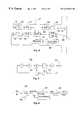
- FIG. 3presents as a block diagram separating the sounds produced by the ear capsule and sounds produced by external noise from a detected microphone signal
- FIG. 4presents as a block diagram the components and connections of an earphone unit according to the invention
- FIG. 5presents the digital shift register equipped with feed-back used for forming an MLS-signal
- FIG. 6presents as a block diagram determining the transfer function between a microphone and an ear capsule
- FIG. 7presents the band limiting frequencies used in an embodiment according to he invention
- FIG. 8presents microphone signal detected in the auditory tube at frequency level
- FIG. 9presents band-limited microphone signal detected in the auditory tube at frequency level
- FIG. 10presents band-limited microphone signal detected in the auditory tube at frequency level, in which the missing frequency bands have been predicted
- FIGS. 11A and 11Bpresent a mobile station according to the invention
- FIGS. 12 and 13present mobile station arrangements according to the invention.
- FIG. 14presents the blocks of digital signal processing carried out in the earphone unit according to the invention.
- FIG. 1presents earphone unit 11 according to the invention, which makes it possible to place microphone capsule 13 and ear capsule 12 in same auditory tube 10 .
- Error microphone 14is located on the outer surface of earphone unit 11 .
- Earphone unit 11has been given such a form that intrusion of external noise 17 ′ into auditory tube 10 has been prevented as efficiently as possible.
- External noise 17 ′consists of e.g. noise produced by working machinery and speech of persons nearby.
- the source of noiseis in FIG. 1 represented by block 17 and the sound advancing from source of noise 17 directly to error microphone 14 is presented with reference 17 ′′.
- the advantage of earphone unit 11is its small size and its suitability for noisy environment.
- Microphone capsule 13 and ear capsule 12can be physically located in relation to each other in a number of ways.
- FIGS. 2A and 2Bpresent alternative placing of microphone capsule 13 , error microphone 14 and ear capsule 12
- FIG. 2Cpresents utilizing of dynamic ear capsule 150 as both microphone capsule 13 and ear capsule 12 .
- microphone capsule 13has as an example been placed in front of ear capsule 12 close to acoustic axis 142 . It is possible to integrate microphone capsule 13 in the body of ear capsule 12 , or it can be mounted using supports 141 .
- Arrow 12 ′presents sound emitted by ear capsule 12 .
- FIG. 2Bpresents a solution in which ear capsule 12 has been installed in the other, auditory tube 10 side, end of earphone unit 11 .
- Ear capsule 12is integrated in the body of earphone unit 11 e.g. using supports 144 .
- Slots or apertures 145have been arranged between the housing of earphone unit 11 and supports 144 to the otherwise closed microphone chamber in which microphone capsule 13 has been placed.
- Microphone capsule 13is integrated in the body of earphone unit 11 or fixed solidly on e.g. supports 146 .
- Space 148has been arranged behind microphone chamber 147 for electric components required by earphone unit 11 , such as processor 34 , amplifiers and A/D and D/A-converters (FIG. 4 ).
- Error microphone 14which has an acoustic connection to noise 17 ′′ arriving from the source of noise 17 has been placed in space 149 in the end of earphone unit 11 opposite to ear capsule 12 .
- FIG. 2Cpresents an embodiment of earphone unit 11 , in which separate ear capsule 12 and microphone capsule 13 have been replaced with dynamic ear capsule 150 which is capable of acting simultaneously as a sound reproducing and receiving component.
- dynamic ear capsules 150e.g. a piezoelectric converters, which have been described in more detail in publication Anderson, E. H. and Hagood, N. W. 1994 Simultaneous piezoelectric sensing/actuation: analysis and applications to controlled structures, Journal of Sound and Vibration, vol 174, 617-639.
- the solution of integrating ear capsule 12 and microphone capsule 13preferably reduces the need for space of earphone unit 11 . Such a construction is also simpler in its mechanical realization. It is also possible to use in the earphone unit 11 according to the invention other ways of placing and realizing microphones 13 and 14 and ear capsule 12 , different in their realization.
- the human speechis generated in the larynx 20 (FIG. 1) in the upper end of the windpipe, in which the vocal cords 15 are situated. From the vocal cords 15 the speech is transferred through the Eustachian tube connecting the throat and the middle ear to the eardrum 16 . Also connected to the eardrum 16 are the auditory ossicles (not shown in the figure) in the middle ear, over which the sound is forwarded into the inner ear (not shown in the figure) where the sensing of sound takes place. The yibrations of the eardrum 16 relays the speech through the auditory tube 10 to the microphone capsule 13 in the auditory tube 10 end of earphone unit 11 . When speech is transferred to the user of earphone unit 11 over ear capsule 12 , this speech is sensed by the eardrum 16 .
- block 24illustrates sound signals received by microphone capsule 13 .
- Theyconsist of three components: speech signal 15 ′ originated in the vocal cords, ear capsule signal 12 ′ reproduced by ear capsule 12 in the auditory tube 10 and noise signal 17 ′′ caused by external sources of noise 17 .
- signals 12 ′ and 17 ′which are disturbing from the point of view of speech signal 15 ′, are strived to be eliminated e.g. in two different stages.
- ear capsule signal 12 ′ generated by ear capsule 12 in the auditory tube 10is removed in block 24 .
- the original electric initiator of ear capsule signal 12 ′is known, it can be subtracted from the signal received by microphone capsule 13 using subtractor 25 provided that the transfer function between ear capsule 12 and microphone capsule 13 is known. Because the transfer function between error microphone 14 and microphone capsule 13 is essentially constant, noise signal 17 ′ can be subtracted in second stage 25 using subtractor 27 using a method which is explained later.
- the transfer function between ear capsule 12 and microphone capsule 13is determined e.g. using so-called MLS (Maximum Length Sequence)-signal.
- MLSMaximum Length Sequence
- a known MLS-signalis fed into the auditory tube 10 with ear capsule 12 , the response caused by which signal is measured with microphone capsule 13 .
- This measuringis executed preferably at such discrete moments when no other information is transferred to the user over ear capsule 12 .
- any sound signalas the known measuring sound signal, but it is nice from the user's point of view to use e.g. the MLS-signal resembling using a generator 50 (FIG.
- FIG. 5presents the realization of generator 50 using a n-stage shift register.
- Output 53 of the generatoris, with suitably selected feed-backs 51 and 52 , binary sequences repeated identically at certain intervals.
- the sequencesare fed to D/A-converter 33 (FIG. 4 ), and from there further to amplifier 32 and ear capsule 12 .
- the repeating frequency of the sequencesdepends on the number of stages n of the generator and on the choice of feed-back 51 and 52 .
- the longest possible sequence available using n-stage generator 50has the length of 2 n ⁇ 1 bits. For example a 64-stage generator can produce a sequence which is repeated identical only after 600,000 years when 1 MHz clock frequency is used. It is prior known to a person skilled in the art that such long sequences are generally used to simulate real random noise.
- FIG. 6presents determining the transfer function.
- Ear capsule 12is used to feed a known signal f(t) into the auditory tube 10 and the signal is detected using microphone capsule 13 .
- Processor 34saves the supplied signal f(t) in memory 37 .
- signal f(t)is transformed due to the effect of impulse response h(t) (ref. 56 ) into form h(t)*f(t).
- signal h(t)*f(t)is directed to A/D-converter 31 and saved in memory 37 .
- Signal h(t)*f(t)is a convolution of the supplied signal f(t) and the system impulse response h(t) (ref. 56 ).
- the system impulse response h(t)is determined by calculating the cross-correlation, prior known to persons skilled in the art, of the supplied signal f(t) and the received signal h(t)*f(t).
- Impulse response h(t) in time spacecan be converted into the form in frequency space e.g. using FFT (Fast Fourier Transform)-transform 58 , resulting in system transfer function H( ⁇ ).
- FFTFast Fourier Transform
- H( ⁇ )Relatively low signal to noise ratio
- a microphone signalcontains the following sound components:
- m(t)is the sound signal received by microphone capsule 13
- y(t)is ear capsule signal 12 ′ detected by microphone capsule 13
- z(t)is external noise signal 17 ′ detected by microphone capsule 13 .
- equation (1)can be rewritten in form:
- Sound component y(t) detected by microphone capsule 13can be written, utilizing the original known electric signal y′(t) supplied to the ear capsule and the determined impulse response h(t) as follows:
- Error microphone 14is used to compensate for external signal z(t). Error microphone 14 measures external noise z′(t) which is used as a reference signal. When external noise z′(t) reaches microphone capsule 13 it is transformed in a way determined by acoustic transfer function K( ⁇ ) between the microphones. Transfer function K( ⁇ ) and its equivalent k(t) in time space can be determined most preferably in the manufacturing stage of earphone unit 11 , because the coupling between microphones 13 and 14 is constant due to the construction of earphone unit 11 . In this case z(t) can be written, using reference signal z′(t) and impulse response k(t) between the microphones as follows:
- a filteris required for compensating external signal z(t), which filter realizes impulse response k(t).
- the filtercan be constructed using discrete components, but preferably it is realized digitally in processor 34 . Even traditional adaptive echo canceling algorithms can be used for estimating signals y(t) and z(t).
- the acoustic coupling between microphone capsule 13 and error microphone 14can be determined also during the operation of the device. This can be carried out by comparing the microphone signals m(t) and z′(t). When signal y′(t) is 0 and such a moment is found when the user of the device is not speaking, also x(t) is 0. In this case the remaining m(t) is essentially convolution k(t)*z′(t). Transfer function K( ⁇ ) can be determined from the division ratio of frequency space simply:
- the transfer functioncan be converted into the impulse response k(t) of time space using inverse Fourier-transform. This operation can be used e.g. for determining the acoustic leak of earphone unit 11 or as a help to speech synthesis e.g. when editing a user's speech.
- microphone 14can be used even in stead of main microphone 13 . It is possible to realize the choice between microphones 13 and 14 e.g. by comparing the amplitude levels of the microphone signals. In addition to this the microphone signals can be analyzed e.g. using a speech detector (VAD, Voice-Activity Detection) and further through correlation calculation, with which one can confirm that signal z′(t) arriving in error microphone 14 has sufficient resemblance with the processed signal x(t). These actions can be used for preventing noise of nearby machinery or other corresponding source of noise and speech of nearby persons from passing on after the processor. When error microphone 14 is used instead of microphone capsule 13 it is possible to obtain better voice quality in conditions with little noise.
- VADVoice-Activity Detection
- FIG. 4presents in more detail the internal construction of earphone unit 11 .
- the signals from microphone capsule 13 and error microphone 14are amplified in amplifiers 30 and 36 after which they are directed through A/D-converters 31 and 35 to processor 34 .
- processor 34When speech signal or MLS-signal from generator 50 is transferred to the user's auditory tube 10 they are transferred through D/A-converter 33 and amplifier 32 to ear capsule 12 .
- Program codes executed by processor 34are stored in memory 37 , which is used by processor 34 also for storing e.g. the interim data required for determining impulse response h(t).
- Controller 38which typically is a microprocessor, the required A/D- and D/A-converters 39 and processor 34 with memory 37 convert both the incoming and outgoing speech into the form required by transfer path 40 .
- Transfer of speech into both directionscan be carried out in either analogue or digital form to either external terminal device 121 (FIG. 13) or device 100 , 110 (FIGS. 11A, 11 B and 12 ) built in connection with earphone unit 11 .
- the required A/D- and D/A-conversionsare executed with converter 39 .
- the power supply to earphone unit 11can be carried out over transfer path 40 . If earphone unit 11 has been designed for wireless operation, the required means of transmitting and receiving 111 , 113 (FIG. 12A) and the power supply (e.g. a battery, not shown in the figure) are placed e.g. in the ear-mounted part.
- both the user of earphone unit 11 and his speaking partnerare talking simultaneously, a so-called “double-talk” situation occurs.
- speech detectorsare used in both the channel which transfers speech from the user to the mobile communication network (up-link) and in the channel which receives speech from the mobile communication network (down-link).
- the teaching of the adaptive echo cancellatoris temporarily interrupted and its settings are saved. This state can be continued as long as the situation is stable, after which the attenuating of the microphone channel is started. Interrupting the teaching of the echo cancellator is possible because the eventual error is at least in the beginning lower than the up-link and down-link signals.
- FIG. 14presents an embodiment in which microphone signal 13 ′′ and ear capsule signal 12 ′′ transferred to different directions are separated from each other using band-pass filters 132 , 133 , 134 and 137 .
- the band-pass filtersdivide the speech band into sub-bands (references 61 - 68 , FIGS. 7 - 10 ), in which case ear capsule 12 can be run on part of the sub-bands and the signal from microphone capsule 13 is correspondingly forwarded only on sub-bands which remain free.
- FIG. 7presents an example of sub-bands, in which speech signal is transferred to both directions on three different frequency bands. In telephone systems the speech band is typically 300 to 3400 Hz.
- frequency bands 300 to 700 Hz, 1.3 to 1.9 kHz and 2.4 to 3.0 kHz, or sub-bands 62 , 64 and 66are utilized directly.
- the signal repeated by ear capsule 12contains correspondingly frequency bands 700 Hz to 1.3 kHz, 1.9 to 2.4 kHz and 3.0 to 3.4 kHz, or sub-bands 63 , 65 and 67 .
- frequency bands below 300 Hz (reference 61 ) and higher than 3.4 kHz (reference 68 )are not used.
- the number of sub-bandshas not been limited for reasons of principle, but to the more sub-bands the frequency range in use is divided, the better voice quality is obtained. As a counterweight to this the required processing capacity increases.
- band limitingis started using band-pass filters 132 , 133 , 134 and 137 , the last of which comprises three separate filters for the signal from ear capsule 12 .
- band limitingis stopped, in which situation signal 13 ′′ from microphone capsule 13 is connected directly to controller 38 and ear capsule signal 12 ′′ directly from controller 38 to ear capsule 12 .
- Digital signal processingenables improving speech quality during band limiting.
- the contents of the missing sub-bandscan be predicted based upon adjacent sub-bands. This is realized e.g. in frequency level by generating the energy spectrum of a missing sub-band based upon the energy spectrum of the limiting frequency of the previous and the next known sub-band.
- Generating of the missing sub-bandscan be carried out e.g. using curve adaptation of first or higher degree prior known to persons skilled in the art. Even with simple prediction methods, such as curve adaptation of first degree, in most situations a better voice quality is obtained compared to only band limited signal, although due to the far advanced human auditory sense speech signal is intelligible even without predicting the missing sub-bands.
- the predictinghas been described in more detail in connection with the explanation of FIGS. 8 to 10 .
- the predictingis realized using predictor 136 (FIG. 14) in the transmitting end.
- Band-pass filters 132 , 133 and 134 and summing unit 135are used in connection with the predicting.
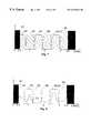
- FIG. 8presents signal 70 in frequency level as measured by microphone capsule 13 in auditory tube 10 .
- the measuring bandis wider than speech band 300 to 3400 Hz and accordingly signal 70 contains also frequency components under 300 Hz and over 3.4 kHz.
- FIGS. 7 to 10it is assumed that double-talk indicator 131 has detected a situation in which both the user of earphone unit 11 and his talking partner are speaking, due to which band limiting is on.
- FIG. 9presents microphone signal 70 in frequency space, limited to sub-bands 62 , 64 and 66 , which signal in its new form consists of three separate components 81 , 82 and 83 of the frequency space.
- band limited microphone signal 70 in frequency spacelooks like in FIG. 9 also in the receiving end, containing components 81 , 82 and 83 .
- the speech signalis badly distorted because e.g. frequency peak 70 ′ (FIG. 10) contained in band 63 is missing totally.
- frequency peak 70 ′FIG. 10
- a curve adaptation of first degreehas been adapted between signal components 81 , 82 and 83 of FIG. 9, in which in all simplicity a straight line has been placed over the missing sub-bands.
- straight line 91is adjusted between the higher limit frequency (700 Hz) of sub-band 81 and the lower limit frequency (1.3 kHz) of sub-band 82 , which gives the contents of sub-band 63 .
- predicting prediction 92is obtained for sub-band 65 and prediction 93 for area 67 .
- sub-band 61 or lower than 300 Hzcan be used, although it contains sounds of the human body, such as heartbeats and sounds of breathing and swallowing.
- the predicted, previously missing signal components 91 , 92 and 93are generated utilizing processor 34 and controller 38 before transferring to A/D- and D/A-converter 39 and transfer path 40 .
- FIGS. 11A and 11Bpresent another embodiment of earphone unit 11 according to the invention.
- earphone unit 11has been integrated in connection with mobile station 100 .
- both ear capsule 12 and microphone capsule 13have been placed in the same end of mobile station 100 .
- Protective element 106made of soft and elastic material, e.g. rubber, has been arranged in connection with ear capsule 12 and microphone capsule 13 .
- the important function of the elementis to prevent external noise 17 ′ form entering the auditory tube 10 when mobile station 100 is lifted on ear 18 in operating position.
- Error microphone 14 used for eliminating external noise 17 ′has been placed in the side edge of mobile station 100 .
- ear capsule 12 and microphone capsule 13are placed next to each other, the distance between the human ear and mouth does not limit the dimensioning of mobile station 100 , in which case mobile station 100 can be realized in even very small size.
- Limitations for the mechanical realization of mobile station 100are set mainly by display 101 , menu keys 102 and numeric keys 103 , unless they are replaced with e.g. a speech-controlled user interface.
- FIG. 12presents another application example of earphone unit 11 according to the invention.
- simplified mobile station 111 with antenna 113has been arranged in connection with earphone unit 11 .
- Simplified mobile station 111comprises a typical mobile station, e.g. a GSM mobile telephone, the typical radio parts prior known to persons skilled in the art and other parts of signal processing, such as the parts for handling the baseband signal for establishing a wireless radio connection to a base station (not shown in the figure).
- a base statione.g. a GSM mobile telephone
- Controller 118can resemble a traditional mobile station or e.g. an infrared controller prior known from television apparatuses.
- Transceiver 115has been arranged to transfer, e.g. in the infrared range, information between controller 118 and transceiver 114 arranged in connection with earphone unit 11 in order to control the operation of mobile station 111 .
- Wireless mobile station 110consisting of earphone unit 11 according to the invention, simplified mobile station 111 and transceiver 114 , can using controller 118 operate preferably as a wireless mobile station mounted in one ear.
- the signal processing required for reducing the size of earphone unit 11can also be realized in processing means 117 arranged in controller 118 .
- FIG. 13presents mobile station system 120 , which consists of earphone unit 11 according to the invention and traditional mobile station 121 .
- Earphone unit 11is connected to mobile station 121 using e.g. connection cable 40 .
- Connection cable 40is used for transferring speech signals in electric form from earphone unit 11 to mobile station 121 and vice versa in either analogue or digital form.
- earphone unit 11for enabling the so called “hands-free” function.
- a separate microphonehas been needed, placed e.g. in connection with connection cable 40 , but by using earphone unit 11 according to the invention a separate microphone is preferably not needed.
- processing means 34 , 37 , 38 essential for the operation of earphone unit 11can be placed either in earphone unit 11 itself, or preferably the functions are carried out in processing means 122 of mobile station 121 , in which case it is possible to realize earphone unit 11 in very small size and at low manufacturing cost. If desired, processing means 34 , 37 , 38 , 39 can also be placed in connector 123 of connection cable 40 . In this case it is possible to connect earphone unit 11 with special connection cable 40 to a standard mobile station, in which specific processing means 122 are not needed.
Landscapes
- Physics & Mathematics (AREA)
- Engineering & Computer Science (AREA)
- Acoustics & Sound (AREA)
- Multimedia (AREA)
- Health & Medical Sciences (AREA)
- Audiology, Speech & Language Pathology (AREA)
- General Health & Medical Sciences (AREA)
- Signal Processing (AREA)
- Headphones And Earphones (AREA)
- Soundproofing, Sound Blocking, And Sound Damping (AREA)
Abstract
Description
Claims (13)
Applications Claiming Priority (2)
| Application Number | Priority Date | Filing Date | Title |
|---|---|---|---|
| FI963173 | 1996-08-13 | ||
| FI963173AFI108909B (en) | 1996-08-13 | 1996-08-13 | Earphone element and terminal |
Publications (1)
| Publication Number | Publication Date |
|---|---|
| US6415034B1true US6415034B1 (en) | 2002-07-02 |
Family
ID=8546485
Family Applications (1)
| Application Number | Title | Priority Date | Filing Date |
|---|---|---|---|
| US08/906,371Expired - LifetimeUS6415034B1 (en) | 1996-08-13 | 1997-08-04 | Earphone unit and a terminal device |
Country Status (2)
| Country | Link |
|---|---|
| US (1) | US6415034B1 (en) |
| FI (1) | FI108909B (en) |
Cited By (102)
| Publication number | Priority date | Publication date | Assignee | Title |
|---|---|---|---|---|
| US20030138111A1 (en)* | 2000-06-09 | 2003-07-24 | Ziyi Cheng | Noise-suppressing receiver |
| US20030165246A1 (en)* | 2002-02-28 | 2003-09-04 | Sintef | Voice detection and discrimination apparatus and method |
| US6661901B1 (en)* | 2000-09-01 | 2003-12-09 | Nacre As | Ear terminal with microphone for natural voice rendition |
| US20040131194A1 (en)* | 2002-10-24 | 2004-07-08 | Andreas Gruhle | Process and device for testing the functionality of loudspeakers |
| WO2005048572A3 (en)* | 2003-11-11 | 2005-10-27 | Matech Inc | Two-way communications device having a single transducer |
| US20060234780A1 (en)* | 2005-04-19 | 2006-10-19 | Ramsden Martin H | Speakerphone with detachable ear bud |
| US20070025561A1 (en)* | 2005-07-28 | 2007-02-01 | Gauger Daniel M Jr | Electronic interfacing with a head-mounted device |
| US20070047739A1 (en)* | 2005-08-26 | 2007-03-01 | Jin-Chou Tsai | Low-noise transmitting receiving earset |
| US20070133820A1 (en)* | 2005-12-14 | 2007-06-14 | Alon Konchitsky | Channel capacity improvement in wireless mobile communications by voice SNR advancements |
| US20070160243A1 (en)* | 2005-12-23 | 2007-07-12 | Phonak Ag | System and method for separation of a user's voice from ambient sound |
| US20070172075A1 (en)* | 2006-01-20 | 2007-07-26 | Alon Konchitsky | Noise canceling method and apparatus increasing channel capacity |
| US20070172074A1 (en)* | 2006-01-20 | 2007-07-26 | Alon Konchitsky | Capacity increase in voice over packets communications systems using novel noise canceling methods and apparatus |
| US20070225035A1 (en)* | 2006-03-27 | 2007-09-27 | Gauger Daniel M Jr | Headset audio accessory |
| US20070274552A1 (en)* | 2006-05-23 | 2007-11-29 | Alon Konchitsky | Environmental noise reduction and cancellation for a communication device including for a wireless and cellular telephone |
| US20080013749A1 (en)* | 2006-05-11 | 2008-01-17 | Alon Konchitsky | Voice coder with two microphone system and strategic microphone placement to deter obstruction for a digital communication device |
| US20080037801A1 (en)* | 2006-08-10 | 2008-02-14 | Cambridge Silicon Radio, Ltd. | Dual microphone noise reduction for headset application |
| US20080044036A1 (en)* | 2006-06-20 | 2008-02-21 | Alon Konchitsky | Noise reduction system and method suitable for hands free communication devices |
| US20080137873A1 (en)* | 2006-11-18 | 2008-06-12 | Personics Holdings Inc. | Method and device for personalized hearing |
| US20080167092A1 (en)* | 2007-01-04 | 2008-07-10 | Joji Ueda | Microphone techniques |
| US20080170515A1 (en)* | 2004-11-10 | 2008-07-17 | Matech, Inc. | Single transducer full duplex talking circuit |
| US20080181442A1 (en)* | 2007-01-30 | 2008-07-31 | Personics Holdings Inc. | Sound pressure level monitoring and notification system |
| US20080192944A1 (en)* | 2004-09-01 | 2008-08-14 | School Juridical Person Of Fukuoka Kogyo Daigaku | Oscillation-Echo Preventing Circuit and Microphone/Speaker Unit |
| US20080240458A1 (en)* | 2006-12-31 | 2008-10-02 | Personics Holdings Inc. | Method and device configured for sound signature detection |
| US20080274764A1 (en)* | 2003-11-11 | 2008-11-06 | Matech, Inc. | Automatic-Switching Wireless Communication Device |
| US20090010444A1 (en)* | 2007-04-27 | 2009-01-08 | Personics Holdings Inc. | Method and device for personalized voice operated control |
| US20090010442A1 (en)* | 2007-06-28 | 2009-01-08 | Personics Holdings Inc. | Method and device for background mitigation |
| US20090022335A1 (en)* | 2007-07-19 | 2009-01-22 | Alon Konchitsky | Dual Adaptive Structure for Speech Enhancement |
| US20090080670A1 (en)* | 2007-09-24 | 2009-03-26 | Sound Innovations Inc. | In-Ear Digital Electronic Noise Cancelling and Communication Device |
| US20090087003A1 (en)* | 2005-01-04 | 2009-04-02 | Zurek Robert A | System and method for determining an in-ear acoustic response for confirming the identity of a user |
| US20090220096A1 (en)* | 2007-11-27 | 2009-09-03 | Personics Holdings, Inc | Method and Device to Maintain Audio Content Level Reproduction |
| US20090248411A1 (en)* | 2008-03-28 | 2009-10-01 | Alon Konchitsky | Front-End Noise Reduction for Speech Recognition Engine |
| US20090310804A1 (en)* | 2008-03-31 | 2009-12-17 | Cochlear Limited | Bone conduction device with a user interface |
| US20100061564A1 (en)* | 2007-02-07 | 2010-03-11 | Richard Clemow | Ambient noise reduction system |
| US20100166206A1 (en)* | 2008-12-29 | 2010-07-01 | Nxp B.V. | Device for and a method of processing audio data |
| WO2010014663A3 (en)* | 2008-07-29 | 2010-07-15 | Dolby Laboratories Licensing Corporation | Method for adaptive control and equalization of electroacoustic channels |
| US20100189268A1 (en)* | 2009-01-23 | 2010-07-29 | Sony Ericsson Mobile Communications Ab | Acoustic in-ear detection for earpiece |
| US20100266136A1 (en)* | 2009-04-15 | 2010-10-21 | Nokia Corporation | Apparatus, method and computer program |
| US20110144984A1 (en)* | 2006-05-11 | 2011-06-16 | Alon Konchitsky | Voice coder with two microphone system and strategic microphone placement to deter obstruction for a digital communication device |
| US20120163623A1 (en)* | 2010-12-22 | 2012-06-28 | Alon Konchitsky | Wideband noise reduction system and a method thereof |
| US20130188807A1 (en)* | 2010-03-12 | 2013-07-25 | Nokia Corporation | Apparatus, Method and Computer Program for Controlling an Acoustic Signal |
| US8606573B2 (en) | 2008-03-28 | 2013-12-10 | Alon Konchitsky | Voice recognition improved accuracy in mobile environments |
| DE102013214309A1 (en) | 2012-07-23 | 2014-01-23 | Sennheiser Electronic Gmbh & Co. Kg | Earphone or headset, has signal processing unit adding processed audio signal from outer microphone to audio signal from inner microphone, and performing band-pass limitation of audio signal of outer microphone |
| WO2014022359A3 (en)* | 2012-07-30 | 2014-03-27 | Personics Holdings, Inc. | Automatic sound pass-through method and system for earphones |
| US20140098019A1 (en)* | 2012-10-05 | 2014-04-10 | Stefan Kristo | Device display label |
| US20140307901A1 (en)* | 2013-04-16 | 2014-10-16 | The Industry & Academic Cooperation In Chungnam National University (Iac) | Method and apparatus for low power operation of binaural hearing aid |
| US20150071462A1 (en)* | 2010-12-22 | 2015-03-12 | Alon Konchitsky | Methods and system for wideband signal processing in communication network |
| US20150104025A1 (en)* | 2007-01-22 | 2015-04-16 | Personics Holdings, LLC. | Method and device for acute sound detection and reproduction |
| US9198800B2 (en) | 2009-10-30 | 2015-12-01 | Etymotic Research, Inc. | Electronic earplug for providing communication and protection |
| US9270244B2 (en) | 2013-03-13 | 2016-02-23 | Personics Holdings, Llc | System and method to detect close voice sources and automatically enhance situation awareness |
| US20160078881A1 (en)* | 2014-09-17 | 2016-03-17 | Haebora Co., Ltd. | Earset and control method for the same |
| US20170148466A1 (en)* | 2015-11-25 | 2017-05-25 | Tim Jackson | Method and system for reducing background sounds in a noisy environment |
| US10012529B2 (en) | 2006-06-01 | 2018-07-03 | Staton Techiya, Llc | Earhealth monitoring system and method II |
| US10045134B2 (en) | 2006-06-14 | 2018-08-07 | Staton Techiya, Llc | Earguard monitoring system |
| US10884696B1 (en) | 2016-09-15 | 2021-01-05 | Human, Incorporated | Dynamic modification of audio signals |
| US20210067938A1 (en)* | 2013-10-06 | 2021-03-04 | Staton Techiya Llc | Methods and systems for establishing and maintaining presence information of neighboring bluetooth devices |
| US20210219051A1 (en)* | 2007-05-04 | 2021-07-15 | Staton Techiya Llc | Method and device for in ear canal echo suppression |
| US20210281945A1 (en)* | 2007-05-04 | 2021-09-09 | Staton Techiya Llc | Method and device for in-ear echo suppression |
| US20210322223A1 (en)* | 2014-12-01 | 2021-10-21 | Staton Techiya Llc | Fixation methods for devices in tubular structures |
| US11217237B2 (en)* | 2008-04-14 | 2022-01-04 | Staton Techiya, Llc | Method and device for voice operated control |
| US11317202B2 (en) | 2007-04-13 | 2022-04-26 | Staton Techiya, Llc | Method and device for voice operated control |
| US20220191608A1 (en) | 2011-06-01 | 2022-06-16 | Staton Techiya Llc | Methods and devices for radio frequency (rf) mitigation proximate the ear |
| US11388500B2 (en) | 2010-06-26 | 2022-07-12 | Staton Techiya, Llc | Methods and devices for occluding an ear canal having a predetermined filter characteristic |
| US11389333B2 (en) | 2009-02-13 | 2022-07-19 | Staton Techiya, Llc | Earplug and pumping systems |
| US11432065B2 (en) | 2017-10-23 | 2022-08-30 | Staton Techiya, Llc | Automatic keyword pass-through system |
| US11430422B2 (en) | 2015-05-29 | 2022-08-30 | Staton Techiya Llc | Methods and devices for attenuating sound in a conduit or chamber |
| US11443746B2 (en) | 2008-09-22 | 2022-09-13 | Staton Techiya, Llc | Personalized sound management and method |
| US11451923B2 (en) | 2018-05-29 | 2022-09-20 | Staton Techiya, Llc | Location based audio signal message processing |
| US11450331B2 (en) | 2006-07-08 | 2022-09-20 | Staton Techiya, Llc | Personal audio assistant device and method |
| US11488590B2 (en) | 2018-05-09 | 2022-11-01 | Staton Techiya Llc | Methods and systems for processing, storing, and publishing data collected by an in-ear device |
| US11489966B2 (en) | 2007-05-04 | 2022-11-01 | Staton Techiya, Llc | Method and apparatus for in-ear canal sound suppression |
| US11504067B2 (en) | 2015-05-08 | 2022-11-22 | Staton Techiya, Llc | Biometric, physiological or environmental monitoring using a closed chamber |
| US11521632B2 (en) | 2006-07-08 | 2022-12-06 | Staton Techiya, Llc | Personal audio assistant device and method |
| US11546698B2 (en) | 2011-03-18 | 2023-01-03 | Staton Techiya, Llc | Earpiece and method for forming an earpiece |
| US11550535B2 (en) | 2007-04-09 | 2023-01-10 | Staton Techiya, Llc | Always on headwear recording system |
| US11551704B2 (en) | 2013-12-23 | 2023-01-10 | Staton Techiya, Llc | Method and device for spectral expansion for an audio signal |
| US11558697B2 (en) | 2018-04-04 | 2023-01-17 | Staton Techiya, Llc | Method to acquire preferred dynamic range function for speech enhancement |
| US11589329B1 (en) | 2010-12-30 | 2023-02-21 | Staton Techiya Llc | Information processing using a population of data acquisition devices |
| US11595771B2 (en) | 2013-10-24 | 2023-02-28 | Staton Techiya, Llc | Method and device for recognition and arbitration of an input connection |
| US11595762B2 (en) | 2016-01-22 | 2023-02-28 | Staton Techiya Llc | System and method for efficiency among devices |
| US11605456B2 (en) | 2007-02-01 | 2023-03-14 | Staton Techiya, Llc | Method and device for audio recording |
| US11605395B2 (en) | 2013-01-15 | 2023-03-14 | Staton Techiya, Llc | Method and device for spectral expansion of an audio signal |
| US11607155B2 (en) | 2018-03-10 | 2023-03-21 | Staton Techiya, Llc | Method to estimate hearing impairment compensation function |
| US11638084B2 (en) | 2018-03-09 | 2023-04-25 | Earsoft, Llc | Eartips and earphone devices, and systems and methods therefor |
| US11638109B2 (en) | 2008-10-15 | 2023-04-25 | Staton Techiya, Llc | Device and method to reduce ear wax clogging of acoustic ports, hearing aid sealing system, and feedback reduction system |
| US11659315B2 (en) | 2012-12-17 | 2023-05-23 | Staton Techiya Llc | Methods and mechanisms for inflation |
| US11665493B2 (en) | 2008-09-19 | 2023-05-30 | Staton Techiya Llc | Acoustic sealing analysis system |
| US11693617B2 (en) | 2014-10-24 | 2023-07-04 | Staton Techiya Llc | Method and device for acute sound detection and reproduction |
| US11730630B2 (en) | 2012-09-04 | 2023-08-22 | Staton Techiya Llc | Occlusion device capable of occluding an ear canal |
| US11750965B2 (en) | 2007-03-07 | 2023-09-05 | Staton Techiya, Llc | Acoustic dampening compensation system |
| US11759149B2 (en) | 2014-12-10 | 2023-09-19 | Staton Techiya Llc | Membrane and balloon systems and designs for conduits |
| US11853405B2 (en) | 2013-08-22 | 2023-12-26 | Staton Techiya Llc | Methods and systems for a voice ID verification database and service in social networking and commercial business transactions |
| US11917100B2 (en) | 2013-09-22 | 2024-02-27 | Staton Techiya Llc | Real-time voice paging voice augmented caller ID/ring tone alias |
| US11985467B2 (en) | 2018-05-22 | 2024-05-14 | The Diablo Canyon Collective Llc | Hearing sensitivity acquisition methods and devices |
| US12045542B2 (en) | 2018-03-10 | 2024-07-23 | The Diablo Canyon Collective Llc | Earphone software and hardware |
| US12089011B2 (en) | 2008-09-11 | 2024-09-10 | St Famtech, Llc | Method and system for sound monitoring over a network |
| US12174901B2 (en) | 2011-03-28 | 2024-12-24 | Apple Inc. | Methods and systems for searching utilizing acoustical context |
| US12217600B2 (en) | 2007-04-27 | 2025-02-04 | The Diablo Canyon Collective Llc | Designer control devices |
| US12268523B2 (en) | 2015-05-08 | 2025-04-08 | ST R&DTech LLC | Biometric, physiological or environmental monitoring using a closed chamber |
| US12289576B2 (en) | 2007-07-12 | 2025-04-29 | St Tiptech, Llc | Expandable sealing devices and methods |
| US12349097B2 (en) | 2010-12-30 | 2025-07-01 | St Famtech, Llc | Information processing using a population of data acquisition devices |
| US12413892B2 (en) | 2008-10-10 | 2025-09-09 | St Tiptech, Llc | Inverted balloon system and inflation management system |
| US12425759B2 (en) | 2019-04-10 | 2025-09-23 | ST R&DTech LLC | Multi-mic earphone design and assembly |
Citations (19)
| Publication number | Priority date | Publication date | Assignee | Title |
|---|---|---|---|---|
| US3995113A (en) | 1975-07-07 | 1976-11-30 | Okie Tani | Two-way acoustic communication through the ear with acoustic and electric noise reduction |
| GB2226931A (en) | 1989-01-10 | 1990-07-11 | Plessey Co Plc | Portable radio/transmitter |
| US4975967A (en)* | 1988-05-24 | 1990-12-04 | Rasmussen Steen B | Earplug for noise protected communication between the user of the earplug and surroundings |
| US5099519A (en) | 1990-05-29 | 1992-03-24 | Yu Guan | Headphones |
| US5285165A (en) | 1988-05-26 | 1994-02-08 | Renfors Markku K | Noise elimination method |
| WO1994006255A1 (en) | 1992-09-10 | 1994-03-17 | Peer Kuhlmann | An ear microphone for insertion in the ear in connection with portable telephones or radios |
| US5298692A (en)* | 1990-11-09 | 1994-03-29 | Kabushiki Kaisha Pilot | Earpiece for insertion in an ear canal, and an earphone, microphone, and earphone/microphone combination comprising the same |
| US5313661A (en) | 1989-02-10 | 1994-05-17 | Nokia Mobile Phones Ltd. | Method and circuit arrangement for adjusting the volume in a mobile telephone |
| US5343523A (en) | 1992-08-03 | 1994-08-30 | At&T Bell Laboratories | Telephone headset structure for reducing ambient noise |
| EP0637187A1 (en) | 1993-07-28 | 1995-02-01 | Pan Communications, Inc. | Two-way communications earset |
| GB2281004A (en) | 1993-08-11 | 1995-02-15 | Yang Chao Ming | Combined microphone/earphone |
| US5406635A (en) | 1992-02-14 | 1995-04-11 | Nokia Mobile Phones, Ltd. | Noise attenuation system |
| US5426719A (en) | 1992-08-31 | 1995-06-20 | The United States Of America As Represented By The Department Of Health And Human Services | Ear based hearing protector/communication system |
| US5692059A (en)* | 1995-02-24 | 1997-11-25 | Kruger; Frederick M. | Two active element in-the-ear microphone system |
| US5732143A (en)* | 1992-10-29 | 1998-03-24 | Andrea Electronics Corp. | Noise cancellation apparatus |
| US5748725A (en)* | 1993-12-29 | 1998-05-05 | Nec Corporation | Telephone set with background noise suppression function |
| US5790684A (en)* | 1994-12-21 | 1998-08-04 | Matsushita Electric Industrial Co., Ltd. | Transmitting/receiving apparatus for use in telecommunications |
| US5909498A (en)* | 1993-03-25 | 1999-06-01 | Smith; Jerry R. | Transducer device for use with communication apparatus |
| US5933506A (en)* | 1994-05-18 | 1999-08-03 | Nippon Telegraph And Telephone Corporation | Transmitter-receiver having ear-piece type acoustic transducing part |
- 1996
- 1996-08-13FIFI963173Apatent/FI108909B/enactive
- 1997
- 1997-08-04USUS08/906,371patent/US6415034B1/ennot_activeExpired - Lifetime
Patent Citations (19)
| Publication number | Priority date | Publication date | Assignee | Title |
|---|---|---|---|---|
| US3995113A (en) | 1975-07-07 | 1976-11-30 | Okie Tani | Two-way acoustic communication through the ear with acoustic and electric noise reduction |
| US4975967A (en)* | 1988-05-24 | 1990-12-04 | Rasmussen Steen B | Earplug for noise protected communication between the user of the earplug and surroundings |
| US5285165A (en) | 1988-05-26 | 1994-02-08 | Renfors Markku K | Noise elimination method |
| GB2226931A (en) | 1989-01-10 | 1990-07-11 | Plessey Co Plc | Portable radio/transmitter |
| US5313661A (en) | 1989-02-10 | 1994-05-17 | Nokia Mobile Phones Ltd. | Method and circuit arrangement for adjusting the volume in a mobile telephone |
| US5099519A (en) | 1990-05-29 | 1992-03-24 | Yu Guan | Headphones |
| US5298692A (en)* | 1990-11-09 | 1994-03-29 | Kabushiki Kaisha Pilot | Earpiece for insertion in an ear canal, and an earphone, microphone, and earphone/microphone combination comprising the same |
| US5406635A (en) | 1992-02-14 | 1995-04-11 | Nokia Mobile Phones, Ltd. | Noise attenuation system |
| US5343523A (en) | 1992-08-03 | 1994-08-30 | At&T Bell Laboratories | Telephone headset structure for reducing ambient noise |
| US5426719A (en) | 1992-08-31 | 1995-06-20 | The United States Of America As Represented By The Department Of Health And Human Services | Ear based hearing protector/communication system |
| WO1994006255A1 (en) | 1992-09-10 | 1994-03-17 | Peer Kuhlmann | An ear microphone for insertion in the ear in connection with portable telephones or radios |
| US5732143A (en)* | 1992-10-29 | 1998-03-24 | Andrea Electronics Corp. | Noise cancellation apparatus |
| US5909498A (en)* | 1993-03-25 | 1999-06-01 | Smith; Jerry R. | Transducer device for use with communication apparatus |
| EP0637187A1 (en) | 1993-07-28 | 1995-02-01 | Pan Communications, Inc. | Two-way communications earset |
| GB2281004A (en) | 1993-08-11 | 1995-02-15 | Yang Chao Ming | Combined microphone/earphone |
| US5748725A (en)* | 1993-12-29 | 1998-05-05 | Nec Corporation | Telephone set with background noise suppression function |
| US5933506A (en)* | 1994-05-18 | 1999-08-03 | Nippon Telegraph And Telephone Corporation | Transmitter-receiver having ear-piece type acoustic transducing part |
| US5790684A (en)* | 1994-12-21 | 1998-08-04 | Matsushita Electric Industrial Co., Ltd. | Transmitting/receiving apparatus for use in telecommunications |
| US5692059A (en)* | 1995-02-24 | 1997-11-25 | Kruger; Frederick M. | Two active element in-the-ear microphone system |
Non-Patent Citations (2)
| Title |
|---|
| Advanced Engineering Mathematics, sixth edition, pp. 271 & 272, "Convolution. Integral Equations", Erwin Kreyszig. |
| Journal of Sound And Vibration, 1994, vol. 174, pp. 617-639, "Simultaneous Piezoelectric Sensing/Actuation: Analysis And Application to Controlled Structures", Anderson et al. |
Cited By (190)
| Publication number | Priority date | Publication date | Assignee | Title |
|---|---|---|---|---|
| US7227957B2 (en)* | 2000-06-09 | 2007-06-05 | Ziyi Cheng | Noise-suppressing receiver |
| US20030138111A1 (en)* | 2000-06-09 | 2003-07-24 | Ziyi Cheng | Noise-suppressing receiver |
| US6661901B1 (en)* | 2000-09-01 | 2003-12-09 | Nacre As | Ear terminal with microphone for natural voice rendition |
| US20030165246A1 (en)* | 2002-02-28 | 2003-09-04 | Sintef | Voice detection and discrimination apparatus and method |
| US6728385B2 (en)* | 2002-02-28 | 2004-04-27 | Nacre As | Voice detection and discrimination apparatus and method |
| US20040131194A1 (en)* | 2002-10-24 | 2004-07-08 | Andreas Gruhle | Process and device for testing the functionality of loudspeakers |
| JP2009089397A (en)* | 2003-11-11 | 2009-04-23 | Matech Inc | Two-way communication device having single transducer, and method thereof |
| KR100851286B1 (en)* | 2003-11-11 | 2008-08-08 | 마테크, 인코포레이티드 | Bidirectional communication device with a single transducer |
| US20080274764A1 (en)* | 2003-11-11 | 2008-11-06 | Matech, Inc. | Automatic-Switching Wireless Communication Device |
| US7826805B2 (en) | 2003-11-11 | 2010-11-02 | Matech, Inc. | Automatic-switching wireless communication device |
| US20070133442A1 (en)* | 2003-11-11 | 2007-06-14 | Matech, Inc. | Two-way communications device having a single transducer |
| WO2005048572A3 (en)* | 2003-11-11 | 2005-10-27 | Matech Inc | Two-way communications device having a single transducer |
| US7881483B2 (en)* | 2003-11-11 | 2011-02-01 | Matech, Inc. | Two-way communications device having a single transducer |
| EP1683328A4 (en)* | 2003-11-11 | 2008-01-23 | Matech Inc | BILATERAL COMMUNICATION DEVICE EQUIPPED WITH A SINGLE TRANSDUCER |
| RU2370890C2 (en)* | 2003-11-11 | 2009-10-20 | Матек, Инк. | Two-way communication device containing one transducer |
| US20080192944A1 (en)* | 2004-09-01 | 2008-08-14 | School Juridical Person Of Fukuoka Kogyo Daigaku | Oscillation-Echo Preventing Circuit and Microphone/Speaker Unit |
| US8254560B2 (en)* | 2004-09-01 | 2012-08-28 | School Juridical Person Of Fukuoka Kogyo Daigaku | Oscillation-echo preventing circuit and microphone/speaker unit |
| US8315379B2 (en)* | 2004-11-10 | 2012-11-20 | Matech, Inc. | Single transducer full duplex talking circuit |
| US20080170515A1 (en)* | 2004-11-10 | 2008-07-17 | Matech, Inc. | Single transducer full duplex talking circuit |
| US7529379B2 (en) | 2005-01-04 | 2009-05-05 | Motorola, Inc. | System and method for determining an in-ear acoustic response for confirming the identity of a user |
| US20090087003A1 (en)* | 2005-01-04 | 2009-04-02 | Zurek Robert A | System and method for determining an in-ear acoustic response for confirming the identity of a user |
| US20060234780A1 (en)* | 2005-04-19 | 2006-10-19 | Ramsden Martin H | Speakerphone with detachable ear bud |
| US8031878B2 (en)* | 2005-07-28 | 2011-10-04 | Bose Corporation | Electronic interfacing with a head-mounted device |
| US20070025561A1 (en)* | 2005-07-28 | 2007-02-01 | Gauger Daniel M Jr | Electronic interfacing with a head-mounted device |
| WO2007016020A1 (en)* | 2005-07-28 | 2007-02-08 | Bose Corporation | Electronic interfacing with a head-mounted device |
| US20070047739A1 (en)* | 2005-08-26 | 2007-03-01 | Jin-Chou Tsai | Low-noise transmitting receiving earset |
| US7447308B2 (en)* | 2005-08-26 | 2008-11-04 | Jin-Chou Tsai | Low-noise transmitting receiving earset |
| US20070133820A1 (en)* | 2005-12-14 | 2007-06-14 | Alon Konchitsky | Channel capacity improvement in wireless mobile communications by voice SNR advancements |
| US20070160243A1 (en)* | 2005-12-23 | 2007-07-12 | Phonak Ag | System and method for separation of a user's voice from ambient sound |
| US20070172075A1 (en)* | 2006-01-20 | 2007-07-26 | Alon Konchitsky | Noise canceling method and apparatus increasing channel capacity |
| US20070172074A1 (en)* | 2006-01-20 | 2007-07-26 | Alon Konchitsky | Capacity increase in voice over packets communications systems using novel noise canceling methods and apparatus |
| US7627352B2 (en) | 2006-03-27 | 2009-12-01 | Gauger Jr Daniel M | Headset audio accessory |
| US20070225035A1 (en)* | 2006-03-27 | 2007-09-27 | Gauger Daniel M Jr | Headset audio accessory |
| US20080013749A1 (en)* | 2006-05-11 | 2008-01-17 | Alon Konchitsky | Voice coder with two microphone system and strategic microphone placement to deter obstruction for a digital communication device |
| US7761106B2 (en)* | 2006-05-11 | 2010-07-20 | Alon Konchitsky | Voice coder with two microphone system and strategic microphone placement to deter obstruction for a digital communication device |
| US8706482B2 (en) | 2006-05-11 | 2014-04-22 | Nth Data Processing L.L.C. | Voice coder with multiple-microphone system and strategic microphone placement to deter obstruction for a digital communication device |
| US20110144984A1 (en)* | 2006-05-11 | 2011-06-16 | Alon Konchitsky | Voice coder with two microphone system and strategic microphone placement to deter obstruction for a digital communication device |
| US20070274552A1 (en)* | 2006-05-23 | 2007-11-29 | Alon Konchitsky | Environmental noise reduction and cancellation for a communication device including for a wireless and cellular telephone |
| US7742790B2 (en) | 2006-05-23 | 2010-06-22 | Alon Konchitsky | Environmental noise reduction and cancellation for a communication device including for a wireless and cellular telephone |
| US10012529B2 (en) | 2006-06-01 | 2018-07-03 | Staton Techiya, Llc | Earhealth monitoring system and method II |
| US10190904B2 (en) | 2006-06-01 | 2019-01-29 | Staton Techiya, Llc | Earhealth monitoring system and method II |
| US10760948B2 (en) | 2006-06-01 | 2020-09-01 | Staton Techiya, Llc | Earhealth monitoring system and method II |
| US10667067B2 (en) | 2006-06-14 | 2020-05-26 | Staton Techiya, Llc | Earguard monitoring system |
| US11818552B2 (en) | 2006-06-14 | 2023-11-14 | Staton Techiya Llc | Earguard monitoring system |
| US10045134B2 (en) | 2006-06-14 | 2018-08-07 | Staton Techiya, Llc | Earguard monitoring system |
| US11277700B2 (en) | 2006-06-14 | 2022-03-15 | Staton Techiya, Llc | Earguard monitoring system |
| US20080044036A1 (en)* | 2006-06-20 | 2008-02-21 | Alon Konchitsky | Noise reduction system and method suitable for hands free communication devices |
| US7706821B2 (en)* | 2006-06-20 | 2010-04-27 | Alon Konchitsky | Noise reduction system and method suitable for hands free communication devices |
| US11521632B2 (en) | 2006-07-08 | 2022-12-06 | Staton Techiya, Llc | Personal audio assistant device and method |
| US11450331B2 (en) | 2006-07-08 | 2022-09-20 | Staton Techiya, Llc | Personal audio assistant device and method |
| US11848022B2 (en) | 2006-07-08 | 2023-12-19 | Staton Techiya Llc | Personal audio assistant device and method |
| US7773759B2 (en)* | 2006-08-10 | 2010-08-10 | Cambridge Silicon Radio, Ltd. | Dual microphone noise reduction for headset application |
| US20080037801A1 (en)* | 2006-08-10 | 2008-02-14 | Cambridge Silicon Radio, Ltd. | Dual microphone noise reduction for headset application |
| US8774433B2 (en)* | 2006-11-18 | 2014-07-08 | Personics Holdings, Llc | Method and device for personalized hearing |
| US9294856B2 (en) | 2006-11-18 | 2016-03-22 | Personics Holdings, Llc | Method and device for personalized hearing |
| US9332364B2 (en)* | 2006-11-18 | 2016-05-03 | Personics Holdings, L.L.C. | Method and device for personalized hearing |
| US20140247952A1 (en)* | 2006-11-18 | 2014-09-04 | Personics Holdings, Llc | Method and device for personalized hearing |
| US20080137873A1 (en)* | 2006-11-18 | 2008-06-12 | Personics Holdings Inc. | Method and device for personalized hearing |
| US9609424B2 (en) | 2006-11-18 | 2017-03-28 | Personics Holdings, Llc | Method and device for personalized hearing |
| US9456268B2 (en) | 2006-12-31 | 2016-09-27 | Personics Holdings, Llc | Method and device for background mitigation |
| US20080240458A1 (en)* | 2006-12-31 | 2008-10-02 | Personics Holdings Inc. | Method and device configured for sound signature detection |
| US8150044B2 (en) | 2006-12-31 | 2012-04-03 | Personics Holdings Inc. | Method and device configured for sound signature detection |
| US7920903B2 (en) | 2007-01-04 | 2011-04-05 | Bose Corporation | Microphone techniques |
| US20080167092A1 (en)* | 2007-01-04 | 2008-07-10 | Joji Ueda | Microphone techniques |
| US10134377B2 (en)* | 2007-01-22 | 2018-11-20 | Staton Techiya, Llc | Method and device for acute sound detection and reproduction |
| US10535334B2 (en) | 2007-01-22 | 2020-01-14 | Staton Techiya, Llc | Method and device for acute sound detection and reproduction |
| US20150104025A1 (en)* | 2007-01-22 | 2015-04-16 | Personics Holdings, LLC. | Method and device for acute sound detection and reproduction |
| US10810989B2 (en) | 2007-01-22 | 2020-10-20 | Staton Techiya Llc | Method and device for acute sound detection and reproduction |
| US11710473B2 (en) | 2007-01-22 | 2023-07-25 | Staton Techiya Llc | Method and device for acute sound detection and reproduction |
| US8150043B2 (en) | 2007-01-30 | 2012-04-03 | Personics Holdings Inc. | Sound pressure level monitoring and notification system |
| US20080181442A1 (en)* | 2007-01-30 | 2008-07-31 | Personics Holdings Inc. | Sound pressure level monitoring and notification system |
| US11605456B2 (en) | 2007-02-01 | 2023-03-14 | Staton Techiya, Llc | Method and device for audio recording |
| US20100061564A1 (en)* | 2007-02-07 | 2010-03-11 | Richard Clemow | Ambient noise reduction system |
| US12047731B2 (en) | 2007-03-07 | 2024-07-23 | Staton Techiya Llc | Acoustic device and methods |
| US11750965B2 (en) | 2007-03-07 | 2023-09-05 | Staton Techiya, Llc | Acoustic dampening compensation system |
| US11550535B2 (en) | 2007-04-09 | 2023-01-10 | Staton Techiya, Llc | Always on headwear recording system |
| US20140093094A1 (en)* | 2007-04-13 | 2014-04-03 | Personics Holdings Inc. | Method and device for personalized voice operated control |
| US9066167B2 (en)* | 2007-04-13 | 2015-06-23 | Personics Holdings, LLC. | Method and device for personalized voice operated control |
| US12249326B2 (en) | 2007-04-13 | 2025-03-11 | St Case1Tech, Llc | Method and device for voice operated control |
| US11317202B2 (en) | 2007-04-13 | 2022-04-26 | Staton Techiya, Llc | Method and device for voice operated control |
| US8577062B2 (en)* | 2007-04-27 | 2013-11-05 | Personics Holdings Inc. | Device and method for controlling operation of an earpiece based on voice activity in the presence of audio content |
| US20090010444A1 (en)* | 2007-04-27 | 2009-01-08 | Personics Holdings Inc. | Method and device for personalized voice operated control |
| US12217600B2 (en) | 2007-04-27 | 2025-02-04 | The Diablo Canyon Collective Llc | Designer control devices |
| US11489966B2 (en) | 2007-05-04 | 2022-11-01 | Staton Techiya, Llc | Method and apparatus for in-ear canal sound suppression |
| US20210219051A1 (en)* | 2007-05-04 | 2021-07-15 | Staton Techiya Llc | Method and device for in ear canal echo suppression |
| US11856375B2 (en)* | 2007-05-04 | 2023-12-26 | Staton Techiya Llc | Method and device for in-ear echo suppression |
| US11683643B2 (en)* | 2007-05-04 | 2023-06-20 | Staton Techiya Llc | Method and device for in ear canal echo suppression |
| US20210281945A1 (en)* | 2007-05-04 | 2021-09-09 | Staton Techiya Llc | Method and device for in-ear echo suppression |
| US8718305B2 (en)* | 2007-06-28 | 2014-05-06 | Personics Holdings, LLC. | Method and device for background mitigation |
| US20090010442A1 (en)* | 2007-06-28 | 2009-01-08 | Personics Holdings Inc. | Method and device for background mitigation |
| US12289576B2 (en) | 2007-07-12 | 2025-04-29 | St Tiptech, Llc | Expandable sealing devices and methods |
| US20090022335A1 (en)* | 2007-07-19 | 2009-01-22 | Alon Konchitsky | Dual Adaptive Structure for Speech Enhancement |
| US7817808B2 (en) | 2007-07-19 | 2010-10-19 | Alon Konchitsky | Dual adaptive structure for speech enhancement |
| US8385560B2 (en)* | 2007-09-24 | 2013-02-26 | Jason Solbeck | In-ear digital electronic noise cancelling and communication device |
| US20090080670A1 (en)* | 2007-09-24 | 2009-03-26 | Sound Innovations Inc. | In-Ear Digital Electronic Noise Cancelling and Communication Device |
| WO2009042635A1 (en)* | 2007-09-24 | 2009-04-02 | Sound Innovations Inc. | In-ear digital electronic noise cancelling and communication device |
| US8855343B2 (en) | 2007-11-27 | 2014-10-07 | Personics Holdings, LLC. | Method and device to maintain audio content level reproduction |
| US20090220096A1 (en)* | 2007-11-27 | 2009-09-03 | Personics Holdings, Inc | Method and Device to Maintain Audio Content Level Reproduction |
| US8606573B2 (en) | 2008-03-28 | 2013-12-10 | Alon Konchitsky | Voice recognition improved accuracy in mobile environments |
| US20090248411A1 (en)* | 2008-03-28 | 2009-10-01 | Alon Konchitsky | Front-End Noise Reduction for Speech Recognition Engine |
| US20090310804A1 (en)* | 2008-03-31 | 2009-12-17 | Cochlear Limited | Bone conduction device with a user interface |
| US8737649B2 (en)* | 2008-03-31 | 2014-05-27 | Cochlear Limited | Bone conduction device with a user interface |
| US11217237B2 (en)* | 2008-04-14 | 2022-01-04 | Staton Techiya, Llc | Method and device for voice operated control |
| WO2010014663A3 (en)* | 2008-07-29 | 2010-07-15 | Dolby Laboratories Licensing Corporation | Method for adaptive control and equalization of electroacoustic channels |
| US20110142247A1 (en)* | 2008-07-29 | 2011-06-16 | Dolby Laboratories Licensing Corporation | MMethod for Adaptive Control and Equalization of Electroacoustic Channels |
| CN102113346B (en)* | 2008-07-29 | 2013-10-30 | 杜比实验室特许公司 | Method for adaptive control and equalization of electroacoustic channels |
| JP2011530218A (en)* | 2008-07-29 | 2011-12-15 | ドルビー・ラボラトリーズ・ライセンシング・コーポレーション | Methods for adaptive control and equalization of electroacoustic channels. |
| CN102113346A (en)* | 2008-07-29 | 2011-06-29 | 杜比实验室特许公司 | Method for adaptive control and equalization of electroacoustic channels |
| US8693699B2 (en) | 2008-07-29 | 2014-04-08 | Dolby Laboratories Licensing Corporation | Method for adaptive control and equalization of electroacoustic channels |
| US12089011B2 (en) | 2008-09-11 | 2024-09-10 | St Famtech, Llc | Method and system for sound monitoring over a network |
| US11889275B2 (en) | 2008-09-19 | 2024-01-30 | Staton Techiya Llc | Acoustic sealing analysis system |
| US11665493B2 (en) | 2008-09-19 | 2023-05-30 | Staton Techiya Llc | Acoustic sealing analysis system |
| US11610587B2 (en) | 2008-09-22 | 2023-03-21 | Staton Techiya Llc | Personalized sound management and method |
| US11443746B2 (en) | 2008-09-22 | 2022-09-13 | Staton Techiya, Llc | Personalized sound management and method |
| US12374332B2 (en) | 2008-09-22 | 2025-07-29 | ST Fam Tech, LLC | Personalized sound management and method |
| US12183341B2 (en) | 2008-09-22 | 2024-12-31 | St Casestech, Llc | Personalized sound management and method |
| US12413892B2 (en) | 2008-10-10 | 2025-09-09 | St Tiptech, Llc | Inverted balloon system and inflation management system |
| US11638109B2 (en) | 2008-10-15 | 2023-04-25 | Staton Techiya, Llc | Device and method to reduce ear wax clogging of acoustic ports, hearing aid sealing system, and feedback reduction system |
| US20100166206A1 (en)* | 2008-12-29 | 2010-07-01 | Nxp B.V. | Device for and a method of processing audio data |
| US20100189268A1 (en)* | 2009-01-23 | 2010-07-29 | Sony Ericsson Mobile Communications Ab | Acoustic in-ear detection for earpiece |
| US8705784B2 (en)* | 2009-01-23 | 2014-04-22 | Sony Corporation | Acoustic in-ear detection for earpiece |
| US11389333B2 (en) | 2009-02-13 | 2022-07-19 | Staton Techiya, Llc | Earplug and pumping systems |
| US11857396B2 (en) | 2009-02-13 | 2024-01-02 | Staton Techiya Llc | Earplug and pumping systems |
| US20100266136A1 (en)* | 2009-04-15 | 2010-10-21 | Nokia Corporation | Apparatus, method and computer program |
| US8477957B2 (en)* | 2009-04-15 | 2013-07-02 | Nokia Corporation | Apparatus, method and computer program |
| US9198800B2 (en) | 2009-10-30 | 2015-12-01 | Etymotic Research, Inc. | Electronic earplug for providing communication and protection |
| US20130188807A1 (en)* | 2010-03-12 | 2013-07-25 | Nokia Corporation | Apparatus, Method and Computer Program for Controlling an Acoustic Signal |
| US10491994B2 (en)* | 2010-03-12 | 2019-11-26 | Nokia Technologies Oy | Methods and apparatus for adjusting filtering to adjust an acoustic feedback based on acoustic inputs |
| US11611820B2 (en) | 2010-06-26 | 2023-03-21 | Staton Techiya Llc | Methods and devices for occluding an ear canal having a predetermined filter characteristic |
| US11388500B2 (en) | 2010-06-26 | 2022-07-12 | Staton Techiya, Llc | Methods and devices for occluding an ear canal having a predetermined filter characteristic |
| US11832046B2 (en) | 2010-06-26 | 2023-11-28 | Staton Techiya Llc | Methods and devices for occluding an ear canal having a predetermined filter characteristic |
| US20120163623A1 (en)* | 2010-12-22 | 2012-06-28 | Alon Konchitsky | Wideband noise reduction system and a method thereof |
| US9847092B2 (en)* | 2010-12-22 | 2017-12-19 | Alon Konchitsky | Methods and system for wideband signal processing in communication network |
| US20150071462A1 (en)* | 2010-12-22 | 2015-03-12 | Alon Konchitsky | Methods and system for wideband signal processing in communication network |
| US8903107B2 (en)* | 2010-12-22 | 2014-12-02 | Alon Konchitsky | Wideband noise reduction system and a method thereof |
| US12349097B2 (en) | 2010-12-30 | 2025-07-01 | St Famtech, Llc | Information processing using a population of data acquisition devices |
| US11589329B1 (en) | 2010-12-30 | 2023-02-21 | Staton Techiya Llc | Information processing using a population of data acquisition devices |
| US11546698B2 (en) | 2011-03-18 | 2023-01-03 | Staton Techiya, Llc | Earpiece and method for forming an earpiece |
| US12174901B2 (en) | 2011-03-28 | 2024-12-24 | Apple Inc. | Methods and systems for searching utilizing acoustical context |
| US11483641B2 (en) | 2011-06-01 | 2022-10-25 | Staton Techiya, Llc | Methods and devices for radio frequency (RF) mitigation proximate the ear |
| US11729539B2 (en) | 2011-06-01 | 2023-08-15 | Staton Techiya Llc | Methods and devices for radio frequency (RF) mitigation proximate the ear |
| US11832044B2 (en) | 2011-06-01 | 2023-11-28 | Staton Techiya Llc | Methods and devices for radio frequency (RF) mitigation proximate the ear |
| US20220191608A1 (en) | 2011-06-01 | 2022-06-16 | Staton Techiya Llc | Methods and devices for radio frequency (rf) mitigation proximate the ear |
| DE102013214309A1 (en) | 2012-07-23 | 2014-01-23 | Sennheiser Electronic Gmbh & Co. Kg | Earphone or headset, has signal processing unit adding processed audio signal from outer microphone to audio signal from inner microphone, and performing band-pass limitation of audio signal of outer microphone |
| US9398366B2 (en) | 2012-07-23 | 2016-07-19 | Sennheiser Electronic Gmbh & Co. Kg | Handset and headset |
| DE102013214309B4 (en) | 2012-07-23 | 2019-05-29 | Sennheiser Electronic Gmbh & Co. Kg | Handset or headset |
| WO2014022359A3 (en)* | 2012-07-30 | 2014-03-27 | Personics Holdings, Inc. | Automatic sound pass-through method and system for earphones |
| US9491542B2 (en) | 2012-07-30 | 2016-11-08 | Personics Holdings, Llc | Automatic sound pass-through method and system for earphones |
| US11730630B2 (en) | 2012-09-04 | 2023-08-22 | Staton Techiya Llc | Occlusion device capable of occluding an ear canal |
| US20140098019A1 (en)* | 2012-10-05 | 2014-04-10 | Stefan Kristo | Device display label |
| US11659315B2 (en) | 2012-12-17 | 2023-05-23 | Staton Techiya Llc | Methods and mechanisms for inflation |
| US12389154B2 (en) | 2012-12-17 | 2025-08-12 | St Famtech, Llc | Shared earpiece communication |
| US11605395B2 (en) | 2013-01-15 | 2023-03-14 | Staton Techiya, Llc | Method and device for spectral expansion of an audio signal |
| US9270244B2 (en) | 2013-03-13 | 2016-02-23 | Personics Holdings, Llc | System and method to detect close voice sources and automatically enhance situation awareness |
| US9319806B2 (en)* | 2013-04-16 | 2016-04-19 | Samsung Electronics Co., Ltd. | Method and apparatus for low power operation of binaural hearing aid |
| US20140307901A1 (en)* | 2013-04-16 | 2014-10-16 | The Industry & Academic Cooperation In Chungnam National University (Iac) | Method and apparatus for low power operation of binaural hearing aid |
| US11853405B2 (en) | 2013-08-22 | 2023-12-26 | Staton Techiya Llc | Methods and systems for a voice ID verification database and service in social networking and commercial business transactions |
| US12363223B2 (en) | 2013-09-22 | 2025-07-15 | ST R&DTech LLC | Real-time voice paging voice augmented caller ID/ring tone alias |
| US11917100B2 (en) | 2013-09-22 | 2024-02-27 | Staton Techiya Llc | Real-time voice paging voice augmented caller ID/ring tone alias |
| US20210067938A1 (en)* | 2013-10-06 | 2021-03-04 | Staton Techiya Llc | Methods and systems for establishing and maintaining presence information of neighboring bluetooth devices |
| US11570601B2 (en)* | 2013-10-06 | 2023-01-31 | Staton Techiya, Llc | Methods and systems for establishing and maintaining presence information of neighboring bluetooth devices |
| US11595771B2 (en) | 2013-10-24 | 2023-02-28 | Staton Techiya, Llc | Method and device for recognition and arbitration of an input connection |
| US12424235B2 (en) | 2013-12-23 | 2025-09-23 | St R&Dtech, Llc | Method and device for spectral expansion for an audio signal |
| US11551704B2 (en) | 2013-12-23 | 2023-01-10 | Staton Techiya, Llc | Method and device for spectral expansion for an audio signal |
| US11741985B2 (en) | 2013-12-23 | 2023-08-29 | Staton Techiya Llc | Method and device for spectral expansion for an audio signal |
| US9691409B2 (en)* | 2014-09-17 | 2017-06-27 | Haebora Co., Ltd. | Earset and control method for the same |
| US20160078881A1 (en)* | 2014-09-17 | 2016-03-17 | Haebora Co., Ltd. | Earset and control method for the same |
| US11693617B2 (en) | 2014-10-24 | 2023-07-04 | Staton Techiya Llc | Method and device for acute sound detection and reproduction |
| US20210322223A1 (en)* | 2014-12-01 | 2021-10-21 | Staton Techiya Llc | Fixation methods for devices in tubular structures |
| US11759149B2 (en) | 2014-12-10 | 2023-09-19 | Staton Techiya Llc | Membrane and balloon systems and designs for conduits |
| US12268523B2 (en) | 2015-05-08 | 2025-04-08 | ST R&DTech LLC | Biometric, physiological or environmental monitoring using a closed chamber |
| US11504067B2 (en) | 2015-05-08 | 2022-11-22 | Staton Techiya, Llc | Biometric, physiological or environmental monitoring using a closed chamber |
| US11430422B2 (en) | 2015-05-29 | 2022-08-30 | Staton Techiya Llc | Methods and devices for attenuating sound in a conduit or chamber |
| US11727910B2 (en) | 2015-05-29 | 2023-08-15 | Staton Techiya Llc | Methods and devices for attenuating sound in a conduit or chamber |
| US20170148466A1 (en)* | 2015-11-25 | 2017-05-25 | Tim Jackson | Method and system for reducing background sounds in a noisy environment |
| US11917367B2 (en) | 2016-01-22 | 2024-02-27 | Staton Techiya Llc | System and method for efficiency among devices |
| US11595762B2 (en) | 2016-01-22 | 2023-02-28 | Staton Techiya Llc | System and method for efficiency among devices |
| US10884696B1 (en) | 2016-09-15 | 2021-01-05 | Human, Incorporated | Dynamic modification of audio signals |
| US11432065B2 (en) | 2017-10-23 | 2022-08-30 | Staton Techiya, Llc | Automatic keyword pass-through system |
| US11638084B2 (en) | 2018-03-09 | 2023-04-25 | Earsoft, Llc | Eartips and earphone devices, and systems and methods therefor |
| US12121349B2 (en) | 2018-03-10 | 2024-10-22 | The Diablo Canyon Collective Llc | Method to estimate hearing impairment compensation function |
| US12248730B2 (en) | 2018-03-10 | 2025-03-11 | The Diablo Canyon Collective Llc | Earphone software and hardware |
| US11607155B2 (en) | 2018-03-10 | 2023-03-21 | Staton Techiya, Llc | Method to estimate hearing impairment compensation function |
| US12045542B2 (en) | 2018-03-10 | 2024-07-23 | The Diablo Canyon Collective Llc | Earphone software and hardware |
| US11818545B2 (en) | 2018-04-04 | 2023-11-14 | Staton Techiya Llc | Method to acquire preferred dynamic range function for speech enhancement |
| US11558697B2 (en) | 2018-04-04 | 2023-01-17 | Staton Techiya, Llc | Method to acquire preferred dynamic range function for speech enhancement |
| US11488590B2 (en) | 2018-05-09 | 2022-11-01 | Staton Techiya Llc | Methods and systems for processing, storing, and publishing data collected by an in-ear device |
| US11985467B2 (en) | 2018-05-22 | 2024-05-14 | The Diablo Canyon Collective Llc | Hearing sensitivity acquisition methods and devices |
| US11451923B2 (en) | 2018-05-29 | 2022-09-20 | Staton Techiya, Llc | Location based audio signal message processing |
| US12425759B2 (en) | 2019-04-10 | 2025-09-23 | ST R&DTech LLC | Multi-mic earphone design and assembly |
Also Published As
| Publication number | Publication date |
|---|---|
| FI963173A0 (en) | 1996-08-13 |
| FI963173A7 (en) | 1998-02-14 |
| FI108909B (en) | 2002-04-15 |
Similar Documents
| Publication | Publication Date | Title |
|---|---|---|
| US6415034B1 (en) | Earphone unit and a terminal device | |
| KR102266080B1 (en) | Frequency-dependent sidetone calibration | |
| CN105981408B (en) | System and method for shaping secondary path information between audio channels | |
| US8675884B2 (en) | Method and a system for processing signals | |
| CN107452367B (en) | Coordinated control of adaptive noise cancellation in ear speaker channels | |
| KR102196012B1 (en) | Systems and methods for enhancing performance of audio transducer based on detection of transducer status | |
| US9066167B2 (en) | Method and device for personalized voice operated control | |
| US6690800B2 (en) | Method and apparatus for communication operator privacy | |
| US8972251B2 (en) | Generating a masking signal on an electronic device | |
| US8543061B2 (en) | Cellphone managed hearing eyeglasses | |
| US20060120537A1 (en) | Noise suppressing multi-microphone headset | |
| WO2017117295A1 (en) | Occlusion reduction and active noise reduction based on seal quality | |
| KR20040070219A (en) | Communication device with active equalization and method therefor | |
| US9654855B2 (en) | Self-voice occlusion mitigation in headsets | |
| US10812660B2 (en) | Method and apparatus for in-ear canal sound suppression | |
| CN115176485A (en) | Wireless earphone with listening function | |
| EP0825798A2 (en) | An earphone unit and a terminal device | |
| JP4415831B2 (en) | Mobile communication terminal and method for reducing leaked voice thereof | |
| JPH08340590A (en) | Earphone/microphone set |
Legal Events
| Date | Code | Title | Description |
|---|---|---|---|
| AS | Assignment | Owner name:NOKIA MOBILE PHONES LTD., FINLAND Free format text:ASSIGNMENT OF ASSIGNORS INTEREST;ASSIGNOR:HIETANEN, JARMO;REEL/FRAME:008749/0467 Effective date:19970716 | |
| STCF | Information on status: patent grant | Free format text:PATENTED CASE | |
| FPAY | Fee payment | Year of fee payment:4 | |
| FPAY | Fee payment | Year of fee payment:8 | |
| FEPP | Fee payment procedure | Free format text:PAYOR NUMBER ASSIGNED (ORIGINAL EVENT CODE: ASPN); ENTITY STATUS OF PATENT OWNER: LARGE ENTITY | |
| FPAY | Fee payment | Year of fee payment:12 | |
| AS | Assignment | Owner name:NOKIA TECHNOLOGIES OY, FINLAND Free format text:ASSIGNMENT OF ASSIGNORS INTEREST;ASSIGNOR:NOKIA CORPORATION;REEL/FRAME:036067/0222 Effective date:20150116 | |
| AS | Assignment | Owner name:OMEGA CREDIT OPPORTUNITIES MASTER FUND, LP, NEW YORK Free format text:SECURITY INTEREST;ASSIGNOR:WSOU INVESTMENTS, LLC;REEL/FRAME:043966/0574 Effective date:20170822 Owner name:OMEGA CREDIT OPPORTUNITIES MASTER FUND, LP, NEW YO Free format text:SECURITY INTEREST;ASSIGNOR:WSOU INVESTMENTS, LLC;REEL/FRAME:043966/0574 Effective date:20170822 | |
| AS | Assignment | Owner name:WSOU INVESTMENTS, LLC, CALIFORNIA Free format text:ASSIGNMENT OF ASSIGNORS INTEREST;ASSIGNOR:NOKIA TECHNOLOGIES OY;REEL/FRAME:043953/0822 Effective date:20170722 | |
| AS | Assignment | Owner name:WSOU INVESTMENTS, LLC, CALIFORNIA Free format text:RELEASE BY SECURED PARTY;ASSIGNOR:OCO OPPORTUNITIES MASTER FUND, L.P. (F/K/A OMEGA CREDIT OPPORTUNITIES MASTER FUND LP;REEL/FRAME:049246/0405 Effective date:20190516 |