US6414968B1 - Transmission and detection of data in a dual channel transceiver - Google Patents
Transmission and detection of data in a dual channel transceiverDownload PDFInfo
- Publication number
- US6414968B1 US6414968B1US09/183,565US18356598AUS6414968B1US 6414968 B1US6414968 B1US 6414968B1US 18356598 AUS18356598 AUS 18356598AUS 6414968 B1US6414968 B1US 6414968B1
- Authority
- US
- United States
- Prior art keywords
- channel
- khz
- data
- present
- signal
- Prior art date
- Legal status (The legal status is an assumption and is not a legal conclusion. Google has not performed a legal analysis and makes no representation as to the accuracy of the status listed.)
- Expired - Lifetime
Links
- 238000001514detection methodMethods0.000titleabstractdescription3
- 230000009977dual effectEffects0.000titleabstract2
- 230000005540biological transmissionEffects0.000titledescription18
- 238000000034methodMethods0.000claimsdescription16
- 239000000969carrierSubstances0.000claims3
- 230000001360synchronised effectEffects0.000abstractdescription4
- 238000010586diagramMethods0.000description3
- 230000002452interceptive effectEffects0.000description2
- 210000004027cellAnatomy0.000description1
- 125000004122cyclic groupChemical group0.000description1
- 230000000593degrading effectEffects0.000description1
- 238000011156evaluationMethods0.000description1
- 210000002569neuronAnatomy0.000description1
- 230000008520organizationEffects0.000description1
- 230000001105regulatory effectEffects0.000description1
- 230000000717retained effectEffects0.000description1
Images


Classifications
- H—ELECTRICITY
- H04—ELECTRIC COMMUNICATION TECHNIQUE
- H04B—TRANSMISSION
- H04B3/00—Line transmission systems
- H04B3/54—Systems for transmission via power distribution lines
- H—ELECTRICITY
- H04—ELECTRIC COMMUNICATION TECHNIQUE
- H04B—TRANSMISSION
- H04B2203/00—Indexing scheme relating to line transmission systems
- H04B2203/54—Aspects of powerline communications not already covered by H04B3/54 and its subgroups
- H04B2203/5404—Methods of transmitting or receiving signals via power distribution lines
- H04B2203/5416—Methods of transmitting or receiving signals via power distribution lines by adding signals to the wave form of the power source
- H—ELECTRICITY
- H04—ELECTRIC COMMUNICATION TECHNIQUE
- H04B—TRANSMISSION
- H04B2203/00—Indexing scheme relating to line transmission systems
- H04B2203/54—Aspects of powerline communications not already covered by H04B3/54 and its subgroups
- H04B2203/5404—Methods of transmitting or receiving signals via power distribution lines
- H04B2203/542—Methods of transmitting or receiving signals via power distribution lines using zero crossing information
- H—ELECTRICITY
- H04—ELECTRIC COMMUNICATION TECHNIQUE
- H04B—TRANSMISSION
- H04B2203/00—Indexing scheme relating to line transmission systems
- H04B2203/54—Aspects of powerline communications not already covered by H04B3/54 and its subgroups
- H04B2203/5462—Systems for power line communications
- H04B2203/5495—Systems for power line communications having measurements and testing channel
Definitions
- Transceivers for transmitting and receiving data over power lines as well as over other mediaare well-known.
- binary datais transmitted by modulating a carrier frequency.
- Echelon Corporation of Palo Alto, Californiamanufactures and sells its PLT-21 transceiver which transmits and receives data with a carrier frequency of approximately 131 kHz over power lines.
- PLT-21 transceiverDifferent aspects of this transceiver are described in U.S. Pat. Nos. 5,471,209; 5,463,662; 5,553,081; 5,703,766; 5,701,240 and USSN: 08/661,136; filed Jun. 10, 1996 which is assigned to the assignee of the present invention.
- a method for transmitting data from a transmitter having a first and second channelis described.
- the datais transmitted at a first power level when the data is transmitted on the first channel without transmitting any signal at all on the second channel.
- a retryis made on the second channel with data being transmitted on the second channel at a power level slightly less than the power level used on the first channel.
- a pilot or synchronization signalis simultaneously transmitted on the first channel at a somewhat lower power level. This pilot tone keeps the network timing of transceivers having only the first channel, synchronized and thereby prevents them from transmitting data onto the line at the same time that second channel signals are on the line. If transmissions were to occur on the first channel they would interfere with transmissions being made over the second channel.
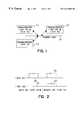
- FIG. 1is a block diagram showing several transceivers connected to a common power line.
- FIG. 2shows waveforms for the two channels, to illustrate the transmission of data and a pilot tone at two different frequencies.
- FIG. 3is a diagram illustrating the packet format for the beginning of the data packets for the two channels.
- FIG. 4is a block diagram showing an apparatus of the present invention used for selecting between the two channels.
- FIG. 5illustrates the method of the present invention.
- a transceiverwhich receives and transmits over two channels, each having a different frequency, is described.
- numerous specific detailsare set forth such as specific frequencies and packet formats, to provide a thorough understanding of the present invention. It will be apparent to one skilled in the art that the present invention may be practiced without these details. In other instances, well-known circuits have not been set forth in detail in order not to obscure the present invention.
- transceivers 11 , 12 and 13are illustrated coupled to a common power line 10 .
- Each of the transceiversis able to transmit data onto and receive data from the power line 10 .
- the transceiver 13is a prior art transceiver such as the PLT-21 transceiver from Echelon Corporation. This transceiver transmits and receives data on a single channel having a carrier frequency of approximately 131 kHz.
- Transceivers 11 and 12are improvements to the transceiver 13 in that transceivers 11 and 12 include a second channel (as well as other improvements). The second channel transmits and receives data at a frequency of approximately 115 kHz. (More precisely the second channel operates at a carrier frequency of 10 MHz ⁇ 86 6/7, and the first channel at 10 MHz ⁇ 76.)
- transceivers 11 and 12are added to a network having transceivers with only a single channel such as transceiver 13 . If transceivers 11 and 12 were to communicate between one another at a frequency of 115 kHz, the transceiver 13 would not detect such transmissions. As such, transceiver 13 may begin transmitting onto the power line while communications are occurring between transceivers 11 and 12 . The transmission from transceiver 13 could interfere with the communications between the transceivers 11 and 12 . For instance, if transceiver 13 is trying to communicate with transceiver 11 or 12 , these transceivers and their associated processors such as the Neuron® cells from Echelon Corporation are busy and unable to process data on two channels at once.
- transceivers 11 and 12operate using the 131 kHz frequency as long as data is being successfully transmitted and received.
- attemptsare first made to transmit data at the frequency of 131 kHz. If no acknowledgement is received, the last two retries are made at the frequency of 115 kHz if the transmitting transceiver has this second channel. If the retries are to a transceiver having a second channel at the 115 kHz frequency, the retry may be more successful than the original transmission.
- noiseoccurs in relatively narrow bands and thus noise which is interfering with a transmission at 131 kHz may not interfere with a transmission at 115 kHz.
- One protocol implemented through these transceiversis the LonTalk® Protocol from Echelon Corporation. With this protocol a bit known as “alternate path” is set whenever the last two tries of a message requesting an acknowledgement is sent. This bit, when received, causes the receiving transceiver to transmit an acknowledgement or response at the 115 kHz when a response is called for.
- a signature of the outgoing messageis generated for each message.
- the transceiverknows to retry the message at the 115 kHz frequency in the case of the unacknowledged repeat message. This retry at 115 kHz can be selected to occur for every other, or every third transmission.
- the transceiveritself controls which frequency is used without disturbing the protocol residing elsewhere in the system. Note, the alternate path bit previously discussed is not set for this mode.
- transceiver 11is transmitting at the 115 kHz frequency and transceivers are on the line 10 of FIG. 1 which transmit and receive only at the 131 kHz frequency such as transceiver 13 .
- the transceiver 13will not detect the 115 kHz carrier from transceiver 11 . Consequently, the transceiver 13 may begin to transmit during the transmission of transceiver 11 since its circuitry believes there is no transmission on the power line.
- transceiver 13begins transmitting when transceiver 11 is transmitting, interference could cause the loss of data.
- All transceiversfavor use of the 131 kHz.
- datasuch as shown by the waveform 20 is transmitted.
- All transceiversdetect the 131 kHz frequency and accordingly will not transmit while another one of the transceivers is transmitting.
- there is no signal on the 115 kHz channelas shown at time 21 of FIG. 2 .
- Those transceivers with the 115 kHz channeldo not transmit if there is a transmission in progress at either 131 kHz or 115 kHz.
- the dataWhen it becomes necessary to transmit data at the 115 kHz frequency, the data is transmitted as shown by waveform 23 .
- a signal as shown by waveform 22is transmitted simultaneously on the 131 kHz channel.
- the signal on this latter channelis not meaningful data, and represents only a synchronization signal or pilot tone.
- the pilot toneis received by all the transceivers and particularly by those which only have the 131 kHz channel.
- a transceiversuch as transceiver 13 detecting the tone, remains synchronized and as such will not transmit data since it is essentially made to believe that data is being transmitted by another transceiver.
- the pilot toneis a string of binary bits that could unintentionally be detected as data by one of the receiving transceivers.
- a cyclic redundancy check (CRC) codethat does not match the string of binary bits in the pilot tone is transmitted with the pilot tone. This causes a processor receiving the pilot tone to reject it.
- the maximum transmission poweris regulated in many countries.
- the total power associated with these waveformscannot exceed the total power associated with the waveform 20 .
- the transmission on the 115 kHz represented by waveform 23is slightly less than the power associated with the waveform 20 .
- the power associated with the waveform 22is also less, for example it is 7 dB below the maximum power transmitted on the 131 kHz channel. This is generally sufficient power for the pilot tone, without significantly degrading the performance of the 115 kHz channel.
- the transceivers of FIG. 1may be used in conjunction with the LonTalk® Protocol as mentioned.
- a typical packet sent with this protocol over the 131 kHz channelis shown in the upper half of FIG. 3 .
- the packetbegins with a bit synchronization signal 31 , also referred to as “dotting.” 24 bit times of dotting are transmitted in order to allow the transceiver to detect the carrier and to synchronize its bit clock. Following this, there is a word synchronization field 32 of eleven bit times to allow word synchronization.
- the receiverif it has properly detected the bit and word synchronization signals, provides a receive enable signal (RXEN) and then data begins to be detected as shown by the first data field 33 .
- RXENreceive enable signal
- the transmission of the 131 kHz pilot tone and data on the 115 kHz channelis shown.
- the data organization on the 115 kHz channelis somewhat different than that on the 131 kHz channel for the LonTalk® Protocol.
- For the 115 kHz channelthere is an initial period 34 that may be 1 to 9 bit times when only the 131 kHz dotting of the 131 kHz channel is transmitted. During this period the 115 kHz channel is determining from the alternate path bit and the signature, if it will be transmitting. Assuming it will transmit, the field 35 having 24 bit times of bit synchronization signals or dotting for the 115 kHz channel is transmitted.
- the 115 k RXEN signaloccurs indicating the transceiver is enabled for the 115 kHz channel. (The other conditions needed before the 115 kHz channel is selected are discussed below.) Note from FIG. 3, that the 131 k RXEN can occur 22-30 bit times before the 115 k RXEN signal, this is discussed later.
- the receiver for the 131 kHz channeldetects the 131 kHz carder and generates internal signals known as carrier detect (CD 1 and CD 2 ).
- carrier detectCD 1 and CD 2 .
- the corresponding signalsare generated in the 115 kHz channel but are not discussed since they are not needed for the discussion below.
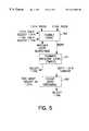
- FIG. 5The method used for assuring that there is data on the 131 kHz channel even if 115 k RXEN is present is shown in FIG. 5 .
- one step in the evaluationis shown by the enable logic step 60 .
- This logicis relatively straight forward as follows: (i) if only 131 k RXEN is present then assume data is present only on the 131 kHz channel, (ii) if only the 115 k RXEN is present, assume that data is only present on the 115 kHz channel, (iii) if neither are present then the transceiver continues to search since it is assumed that there is no data present.
- steps 61 and 62are used to assure that there very likely is no data on the 131 kHz channel and thus the 115 kHz channel should be selected.
- step 61the relative signal strength in the channels is examined. If the signal level in the 115 kHz channel is at least 24 dB lower than in the 131 kHz channel, this is one condition that is considered in selecting the 131 kHz channel. This relative signal strength is measured at two different times as will be described in conjunction with FIG. 4 . In the receiver the input signal is resolved into two quadrature base band signals as is often done in the prior art. These signals are generally referred to as the I and Q signals. Another condition shown by step 62 , is the number of zero crossings in the larger of the I signal and the Q signal of the 115 kHz signal.
- the number of zero crossingsare counted for the bit time preceding the occurrence of the second carrier detect signal in the 131 kHz channel (CD 2 ). If this count is 4 or greater, then in one embodiment of the present invention, it is assumed that noise is being detected in the 115 kHz channel and the 131 kHz channel is selected.
- the prior art transceiversinclude a circuit 40 for determining, essentially, the magnitude (absolute value) of the base band signal. In fact, it is an approximation of the magnitude. Rather than compute the square root of the sum of the squares of the signals in the I and Q channels, the sum of the magnitude of the I and Q signals is used. Thus the output of the circuit 40 for the 131 kHz channel represents the magnitude of the data signal received on the 131 kHz channel.
- the transceiveralso includes a circuit 41 which detects the minimum magnitude signal from the circuit 40 for each bit time.
- This circuitis used for other purposes in the transceiver, but is also used in the circuit of FIG. 4 . It is the maximum signal level that is needed in the comparison of the present invention not the minimum, as discussed above.
- the maximum magnitudeis developed from the minimum magnitude by waiting 8 counts after the detection of the minimum, before accepting the output of the circuit 40 as the maximum.
- the sample clock for the signal at this point in the receiveris 16 ⁇ the bit rate. Consequently, the maximum should occur 8 counts after the minimum is detected.
- the counter 42which is reset when the minimum occurs, counts to 8 and when the 8th count is reached, the output of the circuit 40 is transferred into the register 43 . This is done in synchronous with the sample clock so that the proper value is transferred into the register 43 . The result is that for each bit time the maximum value for the 131 kHz channel is stored in the register 43 .
- the same circuitryis duplicated for the 115 kHz channel, it includes the circuit 50 which determines the magnitude of the I and Q signals, and the circuit 51 which determines the minimum magnitude.
- the circuit 51causes the 8 bit counter 52 to be reset and again the counter is clocked by the 16 ⁇ bit clock.
- the register 53records the output of the circuit 50 which represents the maximum magnitude for each bit time in the 115 kHz channel.
- the samples in the I and Q channelare represented as floating point numbers having an exponent and mantissa.
- the registers 43 and 53capture only the exponent value.
- the comparisondetermines whether the value from register 43 is 24 dB above the value from register 53 .
- the accuracy of this determinationis +/ ⁇ 6 dB.
- the comparison of the contents of registers 43 and 53is made at two different times in one embodiment of the invention.
- the first timeis when CD 2 occurs in the 131 kHz channel, and thereafter, when the RXEN signal occurs in the 131 kHz channel. In each of these times, if the value in register 43 is 24 dB+/ ⁇ 6 dB above the value of the contents of register 53 , then a condition for selecting the 131 kHz signal is met.
- the logic implemented by logic 46is that 3 conditions are needed to select the 131 kHz channel, otherwise the 115 kHz channel is selected.
- the conditionsare: (i) 115 kHz ⁇ 131 kHz by 24 dB at CD 2 , (ii) 115 kHz ⁇ 131 kHz by 24 dB at RXEN in the 131 kHz channel, (iii) 4 zero crossings or more in the larger of the I and Q signals of the 115 kHz signal in the bit time preceding CD 2 in the 131 kHz channel.
- the zero crossing requirementwas previously discussed and in summary, a separate circuit not shown examines the number of zero crossings in the larger of the I and Q signals of the 115 kHz channel for the bit time preceding the occurrence of the 131 k CD 2 signal.
- the number of zero crossings in the channel with the larger signalis retained on an continuous basis within the receiver thus allowing the previous bit time to be examined when the 131 k CD 2 signal becomes active. If there are four or more crossings in the larger of the I or Q signals of the 115 kHz channel, then it is assumed that there is cross-talk and the 131 kHz signal is valid data, provided the comparison tests discussed above indicate a strong signal in the 131 kHz channel. Otherwise the 115 kHz channel is selected.
- an apparatus and methodhas been detected for using two channels in a transceiver both of which operate at different frequencies where only one channel transmits data at a time.
- the transceiverscan be used in networks with transceivers which receive only a single one of the channels.
Landscapes
- Engineering & Computer Science (AREA)
- Power Engineering (AREA)
- Computer Networks & Wireless Communication (AREA)
- Signal Processing (AREA)
- Mobile Radio Communication Systems (AREA)
- Transceivers (AREA)
Abstract
Description
Claims (10)
Priority Applications (2)
| Application Number | Priority Date | Filing Date | Title |
|---|---|---|---|
| US09/183,565US6414968B1 (en) | 1998-10-30 | 1998-10-30 | Transmission and detection of data in a dual channel transceiver |
| EP99308653AEP0998053A3 (en) | 1998-10-30 | 1999-11-01 | Transmission and detection of data in a dual channel transceiver |
Applications Claiming Priority (1)
| Application Number | Priority Date | Filing Date | Title |
|---|---|---|---|
| US09/183,565US6414968B1 (en) | 1998-10-30 | 1998-10-30 | Transmission and detection of data in a dual channel transceiver |
Publications (1)
| Publication Number | Publication Date |
|---|---|
| US6414968B1true US6414968B1 (en) | 2002-07-02 |
Family
ID=22673355
Family Applications (1)
| Application Number | Title | Priority Date | Filing Date |
|---|---|---|---|
| US09/183,565Expired - LifetimeUS6414968B1 (en) | 1998-10-30 | 1998-10-30 | Transmission and detection of data in a dual channel transceiver |
Country Status (2)
| Country | Link |
|---|---|
| US (1) | US6414968B1 (en) |
| EP (1) | EP0998053A3 (en) |
Cited By (7)
| Publication number | Priority date | Publication date | Assignee | Title |
|---|---|---|---|---|
| US20020141523A1 (en)* | 2001-04-03 | 2002-10-03 | Litwin Louis Robert | Time synchronization for data over a powerline modem network |
| US20030057771A1 (en)* | 2001-08-31 | 2003-03-27 | Thorsten Enders | Supply line structure for supplying energy to electrical components of a motor vehicle |
| US20040001438A1 (en)* | 2000-10-31 | 2004-01-01 | Kurt Aretz | Method for avoiding communication collisions between co-existing plc systems on using a physical transmission medium common to all plc systems and arrangement for carrying out said method |
| US20040160990A1 (en)* | 2002-09-25 | 2004-08-19 | Oleg Logvinov | Method and system for timing controlled signal transmission in a point to multipoint power line communications system |
| US20060028997A1 (en)* | 2004-08-09 | 2006-02-09 | Mcfarland Norman R | Wireless building control architecture |
| US8422381B1 (en)* | 2007-02-12 | 2013-04-16 | Rockwell Collins, Inc. | System and method for improved jamming resistance for high throughput point to point communication networks |
| CN114157321A (en)* | 2022-02-09 | 2022-03-08 | 成都嘉纳海威科技有限责任公司 | Double-channel receiving and transmitting multifunctional chip |
Families Citing this family (7)
| Publication number | Priority date | Publication date | Assignee | Title |
|---|---|---|---|---|
| US6414968B1 (en) | 1998-10-30 | 2002-07-02 | Echelon Corporation | Transmission and detection of data in a dual channel transceiver |
| DE10061585B4 (en)* | 2000-12-11 | 2004-01-29 | Siemens Ag | Arrangement and method for data communication in a power distribution network |
| FR2839402B1 (en)* | 2002-05-03 | 2005-03-04 | Defidev | TELECOMMUNICATION CONTROL ON ELECTRICAL NETWORK BY POWER CURRENTS |
| DE502005009320D1 (en)* | 2005-07-29 | 2010-05-12 | Grundfos Management As | Method for data transmission between a pump unit and a control device and a correspondingly designed pump system |
| AU2008274892A1 (en)* | 2007-07-09 | 2009-01-15 | Semitech Semiconductor Pte Ltd | Communication methods and devices |
| DE102012204412A1 (en)* | 2012-03-20 | 2013-09-26 | Zumtobel Lighting Gmbh | Method for transmitting data |
| CN105531940B (en)* | 2014-08-14 | 2018-05-04 | 华为技术有限公司 | The methods, devices and systems of time synchronization |
Citations (13)
| Publication number | Priority date | Publication date | Assignee | Title |
|---|---|---|---|---|
| US3253259A (en)* | 1961-09-19 | 1966-05-24 | Bell Telephone Labor Inc | Plural channel data transmission system having means for utilizing only the operative channels |
| US4809296A (en) | 1986-02-27 | 1989-02-28 | Bbc Brown, Boveri Ltd. | Method for transmitting data via the lines of a power supply system |
| US5239306A (en)* | 1990-12-24 | 1993-08-24 | Motorola, Inc. | Dual mode receiver having battery saving capability |
| US5355114A (en) | 1991-05-10 | 1994-10-11 | Echelon Corporation | Reconstruction of signals using redundant channels |
| US5463662A (en) | 1994-04-08 | 1995-10-31 | Echelon Corporation | Apparatus and method for reducing errors in data caused by noise through use of blanking |
| US5471209A (en) | 1994-03-03 | 1995-11-28 | Echelon Corporation | Sigma-delta converter having a digital logic gate core |
| US5553081A (en) | 1994-04-08 | 1996-09-03 | Echelon Corporation | Apparatus and method for detecting a signal in a communications system |
| US5598221A (en)* | 1994-01-24 | 1997-01-28 | Kabushiki Kaisha Toshiba | Broadcasting system discriminating television receiver for differentiating between analog and digital telecast signals |
| EP0756389A1 (en) | 1995-07-13 | 1997-01-29 | STMicroelectronics S.A. | Assignment circuit for a transmission channel on the mains network |
| US5701240A (en) | 1996-03-05 | 1997-12-23 | Echelon Corporation | Apparatus for powering a transmitter from a switched leg |
| US5703766A (en) | 1996-03-05 | 1997-12-30 | Echelon Corporation | Capacitor power supply for intermittent transmission |
| EP0998053A2 (en) | 1998-10-30 | 2000-05-03 | Echelon Corporation | Transmission and detection of data in a dual channel transceiver |
| US6084926A (en)* | 1997-12-08 | 2000-07-04 | Ericsson Inc. | Method and system for demodulating radio signals |
- 1998
- 1998-10-30USUS09/183,565patent/US6414968B1/ennot_activeExpired - Lifetime
- 1999
- 1999-11-01EPEP99308653Apatent/EP0998053A3/ennot_activeWithdrawn
Patent Citations (13)
| Publication number | Priority date | Publication date | Assignee | Title |
|---|---|---|---|---|
| US3253259A (en)* | 1961-09-19 | 1966-05-24 | Bell Telephone Labor Inc | Plural channel data transmission system having means for utilizing only the operative channels |
| US4809296A (en) | 1986-02-27 | 1989-02-28 | Bbc Brown, Boveri Ltd. | Method for transmitting data via the lines of a power supply system |
| US5239306A (en)* | 1990-12-24 | 1993-08-24 | Motorola, Inc. | Dual mode receiver having battery saving capability |
| US5355114A (en) | 1991-05-10 | 1994-10-11 | Echelon Corporation | Reconstruction of signals using redundant channels |
| US5598221A (en)* | 1994-01-24 | 1997-01-28 | Kabushiki Kaisha Toshiba | Broadcasting system discriminating television receiver for differentiating between analog and digital telecast signals |
| US5471209A (en) | 1994-03-03 | 1995-11-28 | Echelon Corporation | Sigma-delta converter having a digital logic gate core |
| US5553081A (en) | 1994-04-08 | 1996-09-03 | Echelon Corporation | Apparatus and method for detecting a signal in a communications system |
| US5463662A (en) | 1994-04-08 | 1995-10-31 | Echelon Corporation | Apparatus and method for reducing errors in data caused by noise through use of blanking |
| EP0756389A1 (en) | 1995-07-13 | 1997-01-29 | STMicroelectronics S.A. | Assignment circuit for a transmission channel on the mains network |
| US5701240A (en) | 1996-03-05 | 1997-12-23 | Echelon Corporation | Apparatus for powering a transmitter from a switched leg |
| US5703766A (en) | 1996-03-05 | 1997-12-30 | Echelon Corporation | Capacitor power supply for intermittent transmission |
| US6084926A (en)* | 1997-12-08 | 2000-07-04 | Ericsson Inc. | Method and system for demodulating radio signals |
| EP0998053A2 (en) | 1998-10-30 | 2000-05-03 | Echelon Corporation | Transmission and detection of data in a dual channel transceiver |
Non-Patent Citations (1)
| Title |
|---|
| LonWorks PLT-21 Power Line Transceiver User's Guide, Version 2, Echelon Corporation, 1996-1997. |
Cited By (13)
| Publication number | Priority date | Publication date | Assignee | Title |
|---|---|---|---|---|
| US20040001438A1 (en)* | 2000-10-31 | 2004-01-01 | Kurt Aretz | Method for avoiding communication collisions between co-existing plc systems on using a physical transmission medium common to all plc systems and arrangement for carrying out said method |
| US20020141523A1 (en)* | 2001-04-03 | 2002-10-03 | Litwin Louis Robert | Time synchronization for data over a powerline modem network |
| US6834091B2 (en)* | 2001-04-03 | 2004-12-21 | Thomson Licensing S.A. | Time synchronization for data over a powerline modem network |
| US20030057771A1 (en)* | 2001-08-31 | 2003-03-27 | Thorsten Enders | Supply line structure for supplying energy to electrical components of a motor vehicle |
| US7583181B2 (en)* | 2001-08-31 | 2009-09-01 | Robert Bosch Gmbh | Supply line structure for supplying energy to electrical components of a motor vehicle |
| US7369579B2 (en)* | 2002-09-25 | 2008-05-06 | Oleg Logvinov | Method and system for timing controlled signal transmission in a point to multipoint power line communications system |
| US20040160990A1 (en)* | 2002-09-25 | 2004-08-19 | Oleg Logvinov | Method and system for timing controlled signal transmission in a point to multipoint power line communications system |
| US20060028997A1 (en)* | 2004-08-09 | 2006-02-09 | Mcfarland Norman R | Wireless building control architecture |
| US7860495B2 (en) | 2004-08-09 | 2010-12-28 | Siemens Industry Inc. | Wireless building control architecture |
| US20110070904A1 (en)* | 2004-08-09 | 2011-03-24 | Mcfarland Norman R | Binding Wireless Devices In a Building Automation System |
| US8200273B2 (en) | 2004-08-09 | 2012-06-12 | Siemens Industry, Inc. | Binding wireless devices in a building automation system |
| US8422381B1 (en)* | 2007-02-12 | 2013-04-16 | Rockwell Collins, Inc. | System and method for improved jamming resistance for high throughput point to point communication networks |
| CN114157321A (en)* | 2022-02-09 | 2022-03-08 | 成都嘉纳海威科技有限责任公司 | Double-channel receiving and transmitting multifunctional chip |
Also Published As
| Publication number | Publication date |
|---|---|
| EP0998053A3 (en) | 2002-01-09 |
| EP0998053A2 (en) | 2000-05-03 |
Similar Documents
| Publication | Publication Date | Title |
|---|---|---|
| US6414968B1 (en) | Transmission and detection of data in a dual channel transceiver | |
| US7626996B2 (en) | System for detecting collisions in a shared communications medium | |
| US4409592A (en) | Multipoint packet data communication system using random access and collision detection techniques | |
| US4259663A (en) | Contention interference detection by comparison of transmitted and received signal information | |
| GB2350531A (en) | Measuring bit error rate (BER) in multiple data channels and control channel selection | |
| US11228340B1 (en) | Ethernet link transmit power method based on network provided alien crosstalk feedback | |
| CA1144999A (en) | Arrangement for testing a device provided with an echo canceller | |
| EP0520787B1 (en) | System and method for detecting an improper termination and a short circuit in a network | |
| JP2927220B2 (en) | Detector for the presence of a sequence of FSK modulated signals coming from a modem | |
| US20070165788A1 (en) | Wired transmission line testing method | |
| WO2022257497A1 (en) | Method, remote device, and system compatible with two types of tdd switch signal transmission | |
| MXPA05013955A (en) | Method and system for coded null packet-aided synchronization. | |
| US20070258478A1 (en) | Methods and/or apparatus for link optimization | |
| US6327301B1 (en) | Detection and adaptation to digital network impairments by PCM modems | |
| CA2117238C (en) | Digital supervisory audio tone detector | |
| US7668233B2 (en) | Method of determining jitter and apparatus for determining jitter | |
| JP5170939B2 (en) | Test apparatus and test method | |
| EP1305922B1 (en) | Ground level shift detection in can systems | |
| CA2398484C (en) | Pcm modem adaptation system utilizing a silence period | |
| JPS62501811A (en) | Data bus pilot tone | |
| US10742262B1 (en) | Method and system for ethernet active-pair detection | |
| EP0559354A2 (en) | Method and apparatus for measuring worst case susceptibility of digital microwave radios to multipath fading | |
| US5638449A (en) | Data transmission installation of the radio network type, and corresponding process | |
| JPS6362427A (en) | Detection system for error of data communication | |
| JPS5927640A (en) | Signal collision detecting system |
Legal Events
| Date | Code | Title | Description |
|---|---|---|---|
| AS | Assignment | Owner name:ECHELON CORPORATION, CALIFORNIA Free format text:ASSIGNMENT OF ASSIGNORS INTEREST;ASSIGNORS:SUTTERLIN, PHILIP H.;DOWNEY, WALTER J.;STUBBS, MARK ADRIAN;AND OTHERS;REEL/FRAME:009644/0924 Effective date:19981113 | |
| STCF | Information on status: patent grant | Free format text:PATENTED CASE | |
| FPAY | Fee payment | Year of fee payment:4 | |
| FPAY | Fee payment | Year of fee payment:8 | |
| FPAY | Fee payment | Year of fee payment:12 | |
| AS | Assignment | Owner name:OBSIDIAN AGENCY SERVICES, INC., AS COLLATERAL AGENT, CALIFORNIA Free format text:SECURITY INTEREST;ASSIGNOR:ECHELON CORPORATION;REEL/FRAME:047205/0018 Effective date:20181005 Owner name:OBSIDIAN AGENCY SERVICES, INC., AS COLLATERAL AGEN Free format text:SECURITY INTEREST;ASSIGNOR:ECHELON CORPORATION;REEL/FRAME:047205/0018 Effective date:20181005 | |
| AS | Assignment | Owner name:ECHELON CORPORATION, CALIFORNIA Free format text:RELEASE BY SECURED PARTY;ASSIGNOR:OBSIDIAN AGENCY SERVICES, INC., AS COLLATERAL AGENT;REEL/FRAME:050480/0865 Effective date:20190923 |