US6414801B1 - Catadioptric light emitting diode assembly - Google Patents
Catadioptric light emitting diode assemblyDownload PDFInfo
- Publication number
- US6414801B1 US6414801B1US09/482,669US48266900AUS6414801B1US 6414801 B1US6414801 B1US 6414801B1US 48266900 AUS48266900 AUS 48266900AUS 6414801 B1US6414801 B1US 6414801B1
- Authority
- US
- United States
- Prior art keywords
- light
- emitting diodes
- light emitting
- assembly
- board
- Prior art date
- Legal status (The legal status is an assumption and is not a legal conclusion. Google has not performed a legal analysis and makes no representation as to the accuracy of the status listed.)
- Expired - Lifetime
Links
Images


Classifications
- B—PERFORMING OPERATIONS; TRANSPORTING
- B60—VEHICLES IN GENERAL
- B60Q—ARRANGEMENT OF SIGNALLING OR LIGHTING DEVICES, THE MOUNTING OR SUPPORTING THEREOF OR CIRCUITS THEREFOR, FOR VEHICLES IN GENERAL
- B60Q1/00—Arrangement of optical signalling or lighting devices, the mounting or supporting thereof or circuits therefor
- B60Q1/0029—Spatial arrangement
- B60Q1/0041—Spatial arrangement of several lamps in relation to each other
- B60Q1/0052—Spatial arrangement of several lamps in relation to each other concentric
- B—PERFORMING OPERATIONS; TRANSPORTING
- B60—VEHICLES IN GENERAL
- B60Q—ARRANGEMENT OF SIGNALLING OR LIGHTING DEVICES, THE MOUNTING OR SUPPORTING THEREOF OR CIRCUITS THEREFOR, FOR VEHICLES IN GENERAL
- B60Q1/00—Arrangement of optical signalling or lighting devices, the mounting or supporting thereof or circuits therefor
- B60Q1/0029—Spatial arrangement
- B60Q1/0041—Spatial arrangement of several lamps in relation to each other
- B60Q1/0058—Stacked, i.e. one lamp located behind the other in the optical axis direction
- F—MECHANICAL ENGINEERING; LIGHTING; HEATING; WEAPONS; BLASTING
- F21—LIGHTING
- F21S—NON-PORTABLE LIGHTING DEVICES; SYSTEMS THEREOF; VEHICLE LIGHTING DEVICES SPECIALLY ADAPTED FOR VEHICLE EXTERIORS
- F21S43/00—Signalling devices specially adapted for vehicle exteriors, e.g. brake lamps, direction indicator lights or reversing lights
- F21S43/10—Signalling devices specially adapted for vehicle exteriors, e.g. brake lamps, direction indicator lights or reversing lights characterised by the light source
- F21S43/13—Signalling devices specially adapted for vehicle exteriors, e.g. brake lamps, direction indicator lights or reversing lights characterised by the light source characterised by the type of light source
- F21S43/14—Light emitting diodes [LED]
- F—MECHANICAL ENGINEERING; LIGHTING; HEATING; WEAPONS; BLASTING
- F21—LIGHTING
- F21S—NON-PORTABLE LIGHTING DEVICES; SYSTEMS THEREOF; VEHICLE LIGHTING DEVICES SPECIALLY ADAPTED FOR VEHICLE EXTERIORS
- F21S43/00—Signalling devices specially adapted for vehicle exteriors, e.g. brake lamps, direction indicator lights or reversing lights
- F21S43/20—Signalling devices specially adapted for vehicle exteriors, e.g. brake lamps, direction indicator lights or reversing lights characterised by refractors, transparent cover plates, light guides or filters
- F21S43/26—Refractors, transparent cover plates, light guides or filters not provided in groups F21S43/235 - F21S43/255
- F—MECHANICAL ENGINEERING; LIGHTING; HEATING; WEAPONS; BLASTING
- F21—LIGHTING
- F21S—NON-PORTABLE LIGHTING DEVICES; SYSTEMS THEREOF; VEHICLE LIGHTING DEVICES SPECIALLY ADAPTED FOR VEHICLE EXTERIORS
- F21S43/00—Signalling devices specially adapted for vehicle exteriors, e.g. brake lamps, direction indicator lights or reversing lights
- F21S43/30—Signalling devices specially adapted for vehicle exteriors, e.g. brake lamps, direction indicator lights or reversing lights characterised by reflectors
- F21S43/31—Optical layout thereof
- F—MECHANICAL ENGINEERING; LIGHTING; HEATING; WEAPONS; BLASTING
- F21—LIGHTING
- F21S—NON-PORTABLE LIGHTING DEVICES; SYSTEMS THEREOF; VEHICLE LIGHTING DEVICES SPECIALLY ADAPTED FOR VEHICLE EXTERIORS
- F21S43/00—Signalling devices specially adapted for vehicle exteriors, e.g. brake lamps, direction indicator lights or reversing lights
- F21S43/40—Signalling devices specially adapted for vehicle exteriors, e.g. brake lamps, direction indicator lights or reversing lights characterised by the combination of reflectors and refractors
- F—MECHANICAL ENGINEERING; LIGHTING; HEATING; WEAPONS; BLASTING
- F21—LIGHTING
- F21V—FUNCTIONAL FEATURES OR DETAILS OF LIGHTING DEVICES OR SYSTEMS THEREOF; STRUCTURAL COMBINATIONS OF LIGHTING DEVICES WITH OTHER ARTICLES, NOT OTHERWISE PROVIDED FOR
- F21V29/00—Protecting lighting devices from thermal damage; Cooling or heating arrangements specially adapted for lighting devices or systems
- F21V29/50—Cooling arrangements
- F21V29/70—Cooling arrangements characterised by passive heat-dissipating elements, e.g. heat-sinks
- F—MECHANICAL ENGINEERING; LIGHTING; HEATING; WEAPONS; BLASTING
- F21—LIGHTING
- F21V—FUNCTIONAL FEATURES OR DETAILS OF LIGHTING DEVICES OR SYSTEMS THEREOF; STRUCTURAL COMBINATIONS OF LIGHTING DEVICES WITH OTHER ARTICLES, NOT OTHERWISE PROVIDED FOR
- F21V7/00—Reflectors for light sources
- F21V7/0025—Combination of two or more reflectors for a single light source
- F—MECHANICAL ENGINEERING; LIGHTING; HEATING; WEAPONS; BLASTING
- F21—LIGHTING
- F21S—NON-PORTABLE LIGHTING DEVICES; SYSTEMS THEREOF; VEHICLE LIGHTING DEVICES SPECIALLY ADAPTED FOR VEHICLE EXTERIORS
- F21S45/00—Arrangements within vehicle lighting devices specially adapted for vehicle exteriors, for purposes other than emission or distribution of light
- F21S45/40—Cooling of lighting devices
- F21S45/47—Passive cooling, e.g. using fins, thermal conductive elements or openings
- F—MECHANICAL ENGINEERING; LIGHTING; HEATING; WEAPONS; BLASTING
- F21—LIGHTING
- F21Y—INDEXING SCHEME ASSOCIATED WITH SUBCLASSES F21K, F21L, F21S and F21V, RELATING TO THE FORM OR THE KIND OF THE LIGHT SOURCES OR OF THE COLOUR OF THE LIGHT EMITTED
- F21Y2107/00—Light sources with three-dimensionally disposed light-generating elements
- F21Y2107/60—Light sources with three-dimensionally disposed light-generating elements on stacked substrates
- F—MECHANICAL ENGINEERING; LIGHTING; HEATING; WEAPONS; BLASTING
- F21—LIGHTING
- F21Y—INDEXING SCHEME ASSOCIATED WITH SUBCLASSES F21K, F21L, F21S and F21V, RELATING TO THE FORM OR THE KIND OF THE LIGHT SOURCES OR OF THE COLOUR OF THE LIGHT EMITTED
- F21Y2115/00—Light-generating elements of semiconductor light sources
- F21Y2115/10—Light-emitting diodes [LED]
Definitions
- This inventionrelates generally to the field of automotive lighting. More specifically, this invention relates to the field of daytime running lights for automobiles and trucks and the use of light emitting diodes in such lights.
- Typical automotive lightsutilize incandescent lights as the illuminating element of headlights, daytime running lamps, and other various marker or turn signal lamps.
- incandescent bulbsThe problem with the use of incandescent bulbs is the relatively short life span of such bulbs. A typical lifetime for incandescent bulbs is 1,000 hours of use. Replacing incandescent bulbs results in down time and inefficiencies in terms of use of the vehicle. The need for replacing incandescent bulbs becomes especially problematic with respect to daytime running lamps. These lamps are constantly in use, unlike the intermittent use of the incandescent bulbs in the other types of lamps.
- the incandescent bulbs used in the daytime running lampsneed to be replaced more often. This creates a greater expense for the owners and operators of vehicles utilizing such lamps, as well as the manufacturer of the lamps, should the lamps need to be replaced within any warranty period.
- LEDsLight emitting diodes
- the typical lifetime of a light emitting diodeis approximately 50,000 hours before replacement of the LED is necessary.
- LEDsin lamps used on vehicles, such as daytime running lamps, stop lamps, front and rear turn signal lamps, and parking lamps.
- This type of replacementhas not been feasible because the typical LED does not produce enough light to meet governmental standards in terms of luminous intensity for use on automobiles and trucks.
- typical LEDsdo not emit light over as wide a horizontal and vertical range, as do incandescent bulbs nor do they emit as great a quantity of light. This reduced light emission range and intensity requires the use of large arrays of individual LEDs to produce light over the same emission range as incandescent bulbs.
- incandescent lampover that of a LED lamp.
- a typical LED based lampThrough the lens of a typical LED based lamp, one can see the light emitted from individual LEDs.
- light emitted from lamps using incandescent bulbsappear to be more uniformly distributed.
- This inventionsolves the above-identified problems associated with the use of incandescent bulbs in lamps such as parking lamps, daytime running lamps, and stop and turn signal lamps, while at the same time providing the look and feel, from the viewers' perspective, of an incandescent lamp.
- the SAE Recommended Practicedefines a daytime running lamp as a steady burning lamp that is used to improve the conspicuity of a vehicle from the front when the regular headlamps are not required for driving.
- the light output requirements for daytime running lamps, as described in the SAE Recommended Practice SAE J2087,are as follows:
- the minimum candela power as measured from the center point of the lampmust be 500.
- SAE Recommended Practicedetails other measurement points and the required minimum candela power.
- the luminous intensity as measured from the center point of the lampis the highest required minimum;
- the colorsare selected from the following group of colors: white, white to yellow, white to selective yellow, yellow, or selective yellow; and,
- the daytime running lampshall have a minimum unobstructed effective projected luminous lens area of 40 cm 2 .
- the daytime running lampmust provide an unobstructed view of the outer lens surface area of at least 10 cm 2 measured at 45 degrees to the longitudinal axis of the vehicle.
- the DOT regulationsrequire that a daytime running lamp has a luminous intensity not less than 500 candela at test point H-V (the center of the lamp), nor more than 3,000 candela at any location in the beam.
- the color or frequency of the emitted lightmay be selected from the group: white, white to yellow, white to selective yellow, selective yellow, or yellow. Any LED light assembly must meet such DOT standards in order to be used on automobiles, trucks, tractor-trailers and other commercial vehicles. Preferably, the automobiles, trucks and tractor-trailers will also meet the SAE Recommended Practice guidelines.
- Stop lamps and front and rear turn signal lampsalso must meet certain standards in order to be used on automobiles and tractor-trailers.
- the SAE standard directed to indicator lampsis SAE J2261.
- the requirements for indicator lamps on vehicles over 80 inches (2032 mm) in width, as described in the SAE Standard SAE J2261,are as follows:
- the minimum luminous intensity as measured from the center point of the lampis 200 candela.
- the SAE Standarddetails other measurement points and the required minimum candela.
- the luminous intensity as measured from the center point of the lampis the highest required minimum candle power;
- the minimum luminous intensity as measured from the center point of the lampis 80 candela;
- the minimum luminous intensity as measured from the center point of the lampis 130 candela;
- the color of the front turn signal lampshall be yellow
- the color of the rear-turn signal lampmay be red or yellow
- the color of the rear stop lampshall be red
- the effective projected luminous lighted area of a lampshall be at least 75 cm 2 .
- the minimum luminous intensity as measured from the center point of the lampis 16.8 candela.
- the SAE Standarddetails other measurement points and the required minimum candela. However, the luminous intensity as measured from the center point of the lamps is the highest required minimum candela;
- the color of the parking lightmay be white or yellow
- the lampmust provide a minimum of 13 cm 2 of unobstructed projected area from measurable directions.
- any light emitting diode lamp assemblythat is designed to replace an incandescent bulb assembly for parking lamps, stop and turn lamps, and daytime running lamps.
- the light assembly of the instant inventionincludes light emitting diodes (LEDs) especially suited for use in a daytime running lamp.
- a catadioptric light assemblyis that which both reflects and refracts light.
- the catadioptric light assembly of the instant inventionfurther includes a control circuit board, a first set of LEDs secured to a first board.
- a first collimatoris disposed in line with the first set of LEDs so as to direct the emitted light to a contoured reflective surface.
- the contoured reflective surfacedirects the emitted light to a parabolic reflective surface that re-directs the emitted light, in parallel rays, to a lens.
- the instant inventionalso utilizes a second set of LEDs secured to a second board.
- a second collimatoris disposed in line with the second set of LEDs so as to direct the emitted light from the second set of LEDs to the lens.
- First and second support membersare adapted to receive the first and second boards, respectively.
- the first and second support membersalso function as heat sinks so as to absorb and remove the heat generated by the LEDs.
- the catadioptric light assemblyalso includes a housing in the shape of a parabolic reflector having a parabolic reflecting surface disposed on the inside of the housing that houses the boards, the circuit board, and the collimators.
- a lensis disposed in front of the second collimator and adapted to fit within an opening in the housing.
- FIG. 1Ais a top view of the first collimator of a preferred embodiment of the subject invention.
- FIG. 1Bis a side view of the first collimator of a preferred embodiment of the subject invention.
- FIG. 1Cis a side perspective view of the first collimator of a preferred embodiment of the present invention.
- FIG. 1Dis a top view of the second collimator of a preferred embodiment of the present invention.
- FIG. 2is a three-dimensional top perspective view of the unassembled elements of a preferred embodiment of the present invention with the control circuit board at the top of the assembly.
- FIG. 3is a three-dimensional bottom perspective view of the unassembled elements of a preferred embodiment of the present invention with the control circuit board at the bottom of the assembly.
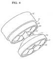
- FIG. 4is a three-dimensional side perspective view of the components depicted in FIGS. 2 and 3 as assembled, in a preferred embodiment of the present LED assembly.
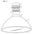
- FIG. 5is a side elevational view of an assembled preferred embodiment of the subject invention about to be inserted into a housing having a parabolic shaped reflective surface.
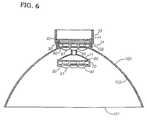
- FIG. 6is a side view of an assembled preferred embodiment of the subject invention as inserted into a housing having a parabolic shaped reflective surface.
- the present inventionis a light emitting diode LED assembly for use in daytime running lamps and indicator lamps.
- the LED assemblyincludes a control circuit board that controls the functioning of the LEDs in the assembly.
- all of the power connectors connecting the LEDs to the power sourceare contained on the control circuit board.
- suitable LEDs for use in this assemblyare the Barracuda Level 1 High Flux Emitter LEDs manufactured by Hewlett-Packard, Model No. HPWL-BD99 and HPWL-BL99.
- this type of LEDis used in conjunction with heat sinks because these LEDs are adapted for high current and high output, both of which result in large amounts of heat that preferably should be drawn away from the LEDs.
- Barracuda LEDsThe radiation pattern of Barracuda LEDs follows the cosine law and presents flat illumination level to secondary optics and delivers a luminous efficiency of approximately 17 lumens per watt.
- Barracuda LEDsare constructed of aluminum indium gallium phosphide (AlInGaP). Barracuda LEDs cannot be soldered by general IR or vapor-phase reflow or wave soldering techniques. Instead, they should be glued with a thermally conductive adhesive to a heat sink and, preferably, potted. While Barracuda LEDs are preferred, one of ordinary skill in the art should readily appreciate that other types of LEDs may be available for use in the subject invention. The LEDs can be any color, including, but not limited to, amber, red, blue, green or white.
- a first support memberis adapted to receive at one end a control circuit board and, at the other end, a first board.
- the first support memberalso acts as a heat sink.
- the first support membermay be constructed of any material that is thermally conductive, such as aluminum or stainless steel.
- the heat sinkis constructed from a lightweight metal material.
- Most preferredis a heat sink that is constructed from lightweight metallic material such as aluminum.
- the first support memberspreferably, has a ridge and a top portion.
- the first boardis adapted to receive a pillar that connects the first set of LEDs in a spaced relationship to a second set of LEDs.
- a first boardhas a plurality of LEDs secured to or embedded in the first board.
- the LEDsmay be embedded on the first board in any typical fashion, including potting, excepting the use of wave soldering.
- the first boardis electrically connected by means of wires to the control circuit board.
- the LEDsare glued to the first heat sink using a thermally conductive adhesive and the first support member possesses receiving elements with which the LEDs mate.
- the receiving elementsstabilize and prevent the movement of the LEDs.
- These receiving elementsmay be protrusions or indentations in a base inside the first support member. Most preferably, the receiving elements are cylindrical protrusions.
- the first boardpossesses a plurality of holes disposed on the board so as to allow the receiving elements from the first support member to contact the plurality of LEDs embedded upon the first board.
- an additional structuremay be attached to the outer surface of the first support member so as to remove the heat more quickly and efficiently than with the use of the first support member.
- This additional structuremay be in the shape of annular fins or rings. However, one of ordinary skill in the art can readily appreciate other shapes and structures that would also assist in the fast and efficient removal of heat from the first support member.
- a first collimatorincludes a plurality of light directing elements.
- the first collimatoris aligned with the first board so as to collect the light emitted from the LEDs and arrange the emitted light from the LEDs into parallel lines.
- the number of light directing elements comprising the collimatorcorresponds in a one-to-one fashion with the number of light emitting diodes disposed on the first board.
- the first collimatormay be constructed of any suitable rigid transparent material, such as various plastic polymers.
- the collimatoris constructed of a transparent rigid plastic material.
- Most preferredis a collimator that is constructed from polycarbonate or acrylic plastic.
- the shape of the collimatoris a plano convex condensing lens.
- the collimatormay be parabolic, elliptical or hyperbolic in shape.
- an additional elementsuch as prisms or pillows or a combination of prisms and pillows, may be added to the light directing elements of the collimator so as to collect and distribute some of the light emanating from the extremes of the LEDs.
- a catadioptric ringmay be added to the collimator so as to receive additional light from the LEDs.
- a second support membermay be constructed of any material that is thermally conductive, such as aluminum.
- the second support memberalso acts as a heat sink.
- the heat sinkis constructed from a lightweight metallic material. More preferred is a second heat sink that is constructed of a lightweight aluminum.
- a connecting membersupports the second support member and joins the second support member, in a spaced relationship, to the first support member.
- the connecting memberextends from the control circuit board through the first support member, the first LED board, and the first collimator, and terminates at the connecting member's to a mirror integral with the second support member.
- the connecting memberalso acts as a conduit for the wires emanating from the first and second boards. The wires provide the electrical connection to the control circuit board.
- the pillarmay be grooved to provide a channel for the wires emanating from the first and second boards to so as to neatly house the wires for connection to the control circuit board.
- the second support memberis adapted to receive a second board upon which is embedded a plurality of LEDs.
- This second set of LEDsmay be embedded on the second board in any typical fashion, including potting, excepting the use of wave soldering.
- the LEDsare glued to the second heat sink using a thermally conductive adhesive and the second heat sink possesses receiving elements with which the LEDs mate. These receiving elements may be protrusions or they may be indentations in a base inside the second heat sink.
- the second boardpossesses a plurality of holes disposed on the board so as to allow the receiving elements from the second heat sink to contact the plurality of LEDs embedded upon the second board.
- a second collimatorcomprising a plurality of light directing elements, is aligned with the second board so as to collect the light emitted from the LEDs and arrange the emitted light from the second set of LEDs in parallel lines.
- the number of light directing elementscorresponds, in a one-to-one fashion, with the number of light emitting diodes.
- the collimatormay be constructed of any suitable rigid transparent material, including glass.
- the reflective surfaceis a mirror.
- the collimatoris constructed of a transparent rigid plastic material. Most preferred is a collimator that is constructed from polycarbonate or acrylic plastic.
- the shape of the collimatoris a piano convex condensing lens.
- the collimatormay be parabolic, elliptical or hyperbolic in shape.
- an additional elementsuch as prisms or pillows or a combination of prisms and pillows, may be added to the light directing elements of the collimator so as to collect and distribute some of the light emanating from the extremes of the LEDs.
- Integral with the second support memberis a mirror that is constructed of any suitable reflective material, including aluminum or glass.
- the mirrorreflects the light emitted from the first collimator.
- the mirrorreflects the directed light to a reflective surface of a generally parabolic-shaped housing.
- the mirroris generally of a parabolic shape.
- at the region wherein the mirror joins with the bottom of the second support memberthe mirror is contoured in a reflex curve area such that stray light may be gathered and reflected to the inner reflective surface of the housing.
- the inner reflective surface of the housingis generally parabolic in shape.
- the inner reflective surfacemay be constructed of any suitable reflective material, such as aluminum.
- the light assemblyfurther includes a housing and a lens. The housing has two openings.
- the first openingis adapted to receive the first support member.
- the second openingis opposite the first and is adapted to receive a lens.
- the parabolic reflective surface of the housingis constructed of a reflective material such as aluminum and may be metallized with aluminum to enhance the reflectivity of the surface.
- the parabolic reflective surfacereflects the light reflected from the mirror in parallel beams to a controlling lens.
- the lensmay be constructed of a transparent rigid material, such as plastic.
- the controlling lenscontains distributive pillow optics to distribute the light directed to the lens in an even manner.
- the reflective surface that is integral with second support memberdistributive pillow optics to distribute the light emitted from the first collimator in a manner such that the lens may be smooth or free from distributive pillow optics at its outer portions.
- the inner portion of the lens that is directly in front of the second board and second collimatorpreferably is pillowed so as to distribute and diffuse the light emitted from the second set of LEDs.
- the first boardincludes six individual LEDs that are arranged in a circular pattern.
- a holeis disposed in the middle of the first board to receive the supporting pillar.
- the LEDsare disposed around the connecting member in this first preferred embodiment.
- the first collimatoralso has six individual light directing elements which correspond to the six LEDs and which are arranged in such a manner that each light directing element is placed directly in front of a corresponding LED.
- the first collimatoralso possesses a hole, through the middle thereof, for receiving the supporting pillar.
- the second LED boardis also substantially circular in shape. Six individual LEDs that are arranged in a circular pattern; however, no hole is provided.
- the second collimatoralso possesses six light directing elements corresponding to the six LEDs and arranged in such a manner that each light directing element is placed directly in front of a corresponding LED.
- the number of LEDscan vary, utilizing either more or less individual LEDs, dependent upon the application for which the assembly is needed.
- a plurality of annular ringsis provided to support the second support member, the second board and the second collimator.
- the annular ringsare supported by the upper surface of the first support member and extend to the second heat sink.
- the plurality of annular ringsare stacked one upon the other so that they enclose the second support member.
- the annular ringsare adapted to receive and support the second support member, second board, and second collimator.
- the annular ringspreferably, are constructed of a transparent material, such as plastic, so as to allow the light reflected from the mirror to pass through the annular rings to the inner reflective surface of the housing for deflection to the lens.
- the annular ringsalso, preferably, have linear prisms disposed along the inner surfaces of the annular rings.
- the linear prismsdistribute light reflected from the mirror evenly such that a diffuse light is reflected from the inner reflective surface of housing to the lens.
- the lens and the mirrormay contain distributive pillow optics to further distribute and diffuse the light emitted from the LEDs.
- an attachment member in a generally circular shapeextends from the inner surface of the lens and supports the second board and second heat sink.
- the attachment membersupports the second board, second collimator, and second support member in a spaced relationship with respect to the first board, first heat sink and first collimator and with respect to the lens.
- the attachment memberconstructed of a transparent and rigid material such as plastic, so as to support the second board and second support member in place during the rigorous environmental conditions to which daytime running, parking and indicator lamps are subjected.
- the attachment membereliminates the need for the supporting pillar described in the previous embodiments, as well as the holes disposed in the first board, first support member and first collimator.
- first collimator 60is circular in shape and possesses a plurality of light directing elements 61 as well as hole 62 in the middle of the first collimator 60 .
- Second collimator 90shown in FIG. 1D, is also circular in shape and possesses a plurality of light directing elements 91 ; however, second collimator 80 lacks a hole.
- LED assembly 10includes circuit board 20 is a printed circuit board that is secured to first support member 30 .
- Control components 21consist of circuitry, including but not limited to diodes and resistors, and serve to allow two intensities of light and are operably connected to by means of wires to the circuit board 20 and actuation devices in the interior of the vehicle.
- First board 40includes a plurality of light emitting diodes 41 embedded therein.
- First support member 30is adapted to receive first board 40 .
- First collimator 60is placed directly in front of first board 40 such that light directing elements 61 are directly in line with LEDs 41 .
- Connecting member 50extends from circuit board 20 through first support member 30 , first board 40 and first collimator 60 .
- Connecting member 50terminates at reflective surface 71 .
- mirror 71is integral with second support member 70 .
- reflective surface 71may also be fixed or removably secured to second support member 70 .
- Reflective surface 50preferably, is hollow but rigid and supports second support member 70 and anchors second heat sink 70 to circuit board 20 .
- Connecting member 50also serves as a conduit for the electrical connecting wires connecting circuit board 20 to the second board 80 .
- housing 100possesses a first opening 102 , a second opening (shown covered by the lens 101 ) and an inner reflective surface 103 .
- First opening 102is adapted to receive LED assembly 10 .
- ridge 31prevents the top portion 32 of heat sink 30 from passing through opening 102 .
- Lens 101distributes and diffuses the light emitted from the LEDs 41 and 81 of first and second boards 40 and 80 , respectively.
- Second support member 70is adapted to receive second board 80 , which includes a plurality of LEDs 81 embedded therein.
- Second support member 80is also adapted to receive second collimator 90 , which possesses a plurality of light directing elements 91 .
- Second collimator 90is placed directly in front of second board 80 .
- Second collimator 90collimates the light emitted by the LEDs 81 . As a result, parallel beams of light exit light directing elements 91 and travel toward lens 101 .
Landscapes
- Engineering & Computer Science (AREA)
- General Engineering & Computer Science (AREA)
- Mechanical Engineering (AREA)
- Physics & Mathematics (AREA)
- Microelectronics & Electronic Packaging (AREA)
- Optics & Photonics (AREA)
- Non-Portable Lighting Devices Or Systems Thereof (AREA)
Abstract
Description
Claims (20)
Priority Applications (1)
| Application Number | Priority Date | Filing Date | Title |
|---|---|---|---|
| US09/482,669US6414801B1 (en) | 1999-01-14 | 2000-01-13 | Catadioptric light emitting diode assembly |
Applications Claiming Priority (2)
| Application Number | Priority Date | Filing Date | Title |
|---|---|---|---|
| US11617999P | 1999-01-14 | 1999-01-14 | |
| US09/482,669US6414801B1 (en) | 1999-01-14 | 2000-01-13 | Catadioptric light emitting diode assembly |
Publications (1)
| Publication Number | Publication Date |
|---|---|
| US6414801B1true US6414801B1 (en) | 2002-07-02 |
Family
ID=26813959
Family Applications (1)
| Application Number | Title | Priority Date | Filing Date |
|---|---|---|---|
| US09/482,669Expired - LifetimeUS6414801B1 (en) | 1999-01-14 | 2000-01-13 | Catadioptric light emitting diode assembly |
Country Status (1)
| Country | Link |
|---|---|
| US (1) | US6414801B1 (en) |
Cited By (84)
| Publication number | Priority date | Publication date | Assignee | Title |
|---|---|---|---|---|
| US20030081419A1 (en)* | 2001-10-25 | 2003-05-01 | Jacob Stephane Frederick | Solid state continuous sealed clean room light fixture |
| US20040066142A1 (en)* | 2002-10-03 | 2004-04-08 | Gelcore, Llc | LED-based modular lamp |
| US20040068305A1 (en)* | 2002-10-07 | 2004-04-08 | Vineet Bansal | Phototherapy system and device |
| EP1431158A1 (en)* | 2002-12-17 | 2004-06-23 | Pintsch Bamag Antriebs- und Verkehrstechnik GmbH | Headlamp and signaling lights for a railway vehicle. |
| WO2004033029A3 (en)* | 2002-10-07 | 2004-06-24 | Natus Medical Inc | Phototherapy system and device |
| US20040149998A1 (en)* | 2002-12-02 | 2004-08-05 | Henson Gordon D. | Illumination system using a plurality of light sources |
| US20040208018A1 (en)* | 2003-04-17 | 2004-10-21 | Sayers Edwin Mitchell | LED headlamp array |
| US6866401B2 (en)* | 2001-12-21 | 2005-03-15 | General Electric Company | Zoomable spot module |
| EP1521033A2 (en) | 2003-09-30 | 2005-04-06 | Osram Sylvania Inc. | Multi-conductor LED bulb assembly, in particular for automobiles |
| US20050110649A1 (en)* | 2003-11-21 | 2005-05-26 | Fredericks Thomas M. | LED aircraft anticollision beacon |
| US20050116177A1 (en)* | 2003-12-02 | 2005-06-02 | 3M Innovative Properties Company | LED modifying apparatus and method |
| US20050116235A1 (en)* | 2003-12-02 | 2005-06-02 | Schultz John C. | Illumination assembly |
| US20050116635A1 (en)* | 2003-12-02 | 2005-06-02 | Walson James E. | Multiple LED source and method for assembling same |
| US20050122713A1 (en)* | 2003-12-03 | 2005-06-09 | Hutchins Donald C. | Lighting |
| US20050134527A1 (en)* | 2003-12-18 | 2005-06-23 | 3M Innovative Properties Company | Display including a solid state light device and method using same |
| US20050140270A1 (en)* | 2003-12-02 | 2005-06-30 | Henson Gordon D. | Solid state light device |
| US20050213341A1 (en)* | 2004-03-25 | 2005-09-29 | Guide Corporation | Led lamp with light pipe for automotive vehicles |
| WO2006017930A1 (en)* | 2004-08-18 | 2006-02-23 | Remco Solid State Lighting Inc. | Led control utilizing dynamic resistance of leds |
| WO2006024196A1 (en)* | 2004-09-01 | 2006-03-09 | Sze Keun Chan | A led lamp |
| US20060087842A1 (en)* | 2002-06-20 | 2006-04-27 | Alessio David J | Led lighting device |
| WO2006061752A1 (en)* | 2004-12-09 | 2006-06-15 | Koninklijke Philips Electronics N.V. | Illumination system |
| US20070164875A1 (en)* | 2003-11-21 | 2007-07-19 | Fredericks Thomas M | LED aircraft anticollision beacon |
| EP1840455A1 (en) | 2006-03-28 | 2007-10-03 | Volkswagen Aktiengesellschaft | Vehicle lighting unit with at least two light sources |
| WO2008023313A1 (en)* | 2006-08-22 | 2008-02-28 | Koninklijke Philips Electronics N.V. | Led assembly for rear lamps in an automobile |
| WO2008051249A1 (en)* | 2006-10-19 | 2008-05-02 | Architectural Arts & Technology, Inc. | Efficient and uniformly distributed illumination from multiple source luminairies |
| GB2445103A (en)* | 2006-12-19 | 2008-06-25 | Richard Weatherley | Lighting system utilising RJ45 patch leads |
| US7403680B2 (en) | 2003-12-02 | 2008-07-22 | 3M Innovative Properties Company | Reflective light coupler |
| US20080192436A1 (en)* | 2007-02-09 | 2008-08-14 | Cooler Master Co., Ltd. | Light emitting device |
| EP1970250A1 (en)* | 2007-03-12 | 2008-09-17 | Odelo GmbH | Lamp for vehicles, in particular motor vehicles |
| US20090015797A1 (en)* | 2005-05-10 | 2009-01-15 | Iwasaki Electric Co., Ltd. | Projector device, laminate type light-emitting diode device, and reflection type light-emitting diode unit |
| WO2009012806A1 (en)* | 2007-07-20 | 2009-01-29 | Osram Gesellschaft mit beschränkter Haftung | Lamp |
| US20090190345A1 (en)* | 2008-01-25 | 2009-07-30 | Belliveau Richard S | Multiparameter stage lighting apparatus with graphical output |
| US20100123008A1 (en)* | 2008-11-18 | 2010-05-20 | Teco Image System Co., Ltd. | Light projecting apparatus of scanner module |
| US20100142215A1 (en)* | 2008-12-10 | 2010-06-10 | Waring Jennifer S | Annular lighting fixture and method for illumination |
| WO2010063534A1 (en)* | 2008-12-05 | 2010-06-10 | Osram Gesellschaft mit beschränkter Haftung | Lamp and method for controlling the lamp |
| WO2010069062A1 (en)* | 2008-12-17 | 2010-06-24 | Eagle Eye Lighting Ltd. | Heat dissipating led street light |
| US20100182783A1 (en)* | 2009-01-17 | 2010-07-22 | Chen Hui Yu | Reflector component for a led lamp |
| US20100201286A1 (en)* | 2003-06-23 | 2010-08-12 | Advanced Optical Technologies, Llc | Optical integrating cavity lighting system using multiple led light sources |
| US20100254128A1 (en)* | 2009-04-06 | 2010-10-07 | Cree Led Lighting Solutions, Inc. | Reflector system for lighting device |
| US20110051422A1 (en)* | 2009-08-31 | 2011-03-03 | Hong Fu Jin Precision Industry (Shenzhen) Co., Ltd | Energy saving lamp |
| WO2012022662A1 (en)* | 2010-08-18 | 2012-02-23 | Osram Opto Semiconductors Gmbh | Light source |
| GB2484379A (en)* | 2010-10-05 | 2012-04-11 | Gm Global Tech Operations Inc | Vehicle headlights with two arrays of LEDs |
| DE102011003411B3 (en)* | 2011-01-31 | 2012-04-26 | Franz Sill Gmbh | LED light |
| US20120112614A1 (en)* | 2010-11-05 | 2012-05-10 | Cree, Inc. | Lighting device with spatially segregated primary and secondary emitters |
| JP4995989B2 (en)* | 2010-10-12 | 2012-08-08 | パナソニック株式会社 | lamp |
| WO2012177428A1 (en)* | 2011-06-23 | 2012-12-27 | Cree, Inc. | Solid state retroreflective directional lamp |
| WO2013086148A1 (en)* | 2011-12-06 | 2013-06-13 | Truck-Lite Co. Llc | Light emitting diode perimeter lamp assembly |
| USD696436S1 (en) | 2011-06-23 | 2013-12-24 | Cree, Inc. | Solid state directional lamp |
| US8616724B2 (en) | 2011-06-23 | 2013-12-31 | Cree, Inc. | Solid state directional lamp including retroreflective, multi-element directional lamp optic |
| US8777455B2 (en) | 2011-06-23 | 2014-07-15 | Cree, Inc. | Retroreflective, multi-element design for a solid state directional lamp |
| US8777463B2 (en) | 2011-06-23 | 2014-07-15 | Cree, Inc. | Hybrid solid state emitter printed circuit board for use in a solid state directional lamp |
| US8888320B2 (en) | 2012-01-27 | 2014-11-18 | Hubbell Incorporated | Prismatic LED module for luminaire |
| USD718897S1 (en)* | 2013-03-15 | 2014-12-02 | Cree, Inc. | Multi-point to single-point optic for a lighting fixture |
| WO2015031162A1 (en)* | 2013-08-27 | 2015-03-05 | Cree, Inc. | Led lamp |
| US9022599B2 (en) | 2013-03-15 | 2015-05-05 | Cree, Inc. | Multi-point to single point optic |
| US20150362145A1 (en)* | 2014-06-12 | 2015-12-17 | Panasonic Intellectual Property Management Co., Ltd. | Lighting apparatus and automobile including the same |
| US9234638B2 (en) | 2012-04-13 | 2016-01-12 | Cree, Inc. | LED lamp with thermally conductive enclosure |
| US9310028B2 (en) | 2012-04-13 | 2016-04-12 | Cree, Inc. | LED lamp with LEDs having a longitudinally directed emission profile |
| US9310065B2 (en) | 2012-04-13 | 2016-04-12 | Cree, Inc. | Gas cooled LED lamp |
| US9322543B2 (en) | 2012-04-13 | 2016-04-26 | Cree, Inc. | Gas cooled LED lamp with heat conductive submount |
| US9353937B2 (en) | 2012-04-13 | 2016-05-31 | Cree, Inc. | Gas cooled LED lamp |
| US9395074B2 (en) | 2012-04-13 | 2016-07-19 | Cree, Inc. | LED lamp with LED assembly on a heat sink tower |
| US9395051B2 (en) | 2012-04-13 | 2016-07-19 | Cree, Inc. | Gas cooled LED lamp |
| US9408282B1 (en)* | 2014-07-21 | 2016-08-02 | Astro, Inc. | Multi-purpose lightbulb |
| US9410687B2 (en) | 2012-04-13 | 2016-08-09 | Cree, Inc. | LED lamp with filament style LED assembly |
| US9470372B2 (en) | 2008-11-26 | 2016-10-18 | Deloren E. Anderson | High intensity replaceable light emitting diode module and array |
| US9546771B2 (en) | 2013-08-26 | 2017-01-17 | GE Lighting Solutions, LLC | Packed pillow optic array |
| US9651240B2 (en) | 2013-11-14 | 2017-05-16 | Cree, Inc. | LED lamp |
| US9784417B1 (en)* | 2014-07-21 | 2017-10-10 | Astro, Inc. | Multi-purpose lightbulb |
| US9951909B2 (en) | 2012-04-13 | 2018-04-24 | Cree, Inc. | LED lamp |
| US20180327115A1 (en)* | 2017-05-09 | 2018-11-15 | Eaton Intelligent Power Limited | Airfield light |
| US20190032908A1 (en)* | 2016-03-29 | 2019-01-31 | Honda Motor Co., Ltd. | Light device |
| US10422505B2 (en)* | 2015-12-02 | 2019-09-24 | Lg Innotek Co., Ltd. | Lighting device and vehicle lamp comprising same |
| USD881966S1 (en)* | 2018-05-16 | 2020-04-21 | Plasser & Theurer, Export von Bahnbaumaschinen, Gesellschaft m.b.H. | Catadioptric reflector |
| US10825313B2 (en) | 2018-03-30 | 2020-11-03 | Carrier Corporation | Hazard detector with optical status indicator |
| US10957830B2 (en) | 2011-06-24 | 2021-03-23 | Cree, Inc. | High voltage monolithic LED chip with improved reliability |
| US11041604B2 (en) | 2019-08-22 | 2021-06-22 | Ford Global Technologies, Llc | Vehicle cargo lamp |
| US11225299B2 (en)* | 2019-07-31 | 2022-01-18 | Niterider Technical Lighting & Video Systems, Inc. | Light assembly |
| US11354995B2 (en) | 2017-07-10 | 2022-06-07 | Carrier Corporation | Hazard detector with optical status indicator |
| US20220325867A1 (en)* | 2021-04-07 | 2022-10-13 | Ford Global Technologies, Llc | High Efficiency Vehicle Backup Lamps |
| US11655955B1 (en)* | 2022-08-05 | 2023-05-23 | Min Hsiang Corporation | Vehicle lamp structure |
| US11670900B2 (en) | 2019-02-05 | 2023-06-06 | Emergency Technology, Inc. | Universal smart adaptor |
| US12094326B2 (en) | 2018-03-30 | 2024-09-17 | Carrier Corporation | Lens for a visual alarm detector |
| US12444894B2 (en) | 2023-04-20 | 2025-10-14 | Emergency Technology, Inc. | Smart adaptor assembly |
Citations (2)
| Publication number | Priority date | Publication date | Assignee | Title |
|---|---|---|---|---|
| US5590547A (en)* | 1993-04-21 | 1997-01-07 | Sipra Patententwicklungs-U.Beteiligungsgesellschaft Mbh | Yarn feeder device utilizing position sensors to maintain yarn wrap |
| US5984494A (en)* | 1995-09-08 | 1999-11-16 | Jimmy G. Cook | Light shield for an illumination system |
- 2000
- 2000-01-13USUS09/482,669patent/US6414801B1/ennot_activeExpired - Lifetime
Patent Citations (2)
| Publication number | Priority date | Publication date | Assignee | Title |
|---|---|---|---|---|
| US5590547A (en)* | 1993-04-21 | 1997-01-07 | Sipra Patententwicklungs-U.Beteiligungsgesellschaft Mbh | Yarn feeder device utilizing position sensors to maintain yarn wrap |
| US5984494A (en)* | 1995-09-08 | 1999-11-16 | Jimmy G. Cook | Light shield for an illumination system |
Cited By (161)
| Publication number | Priority date | Publication date | Assignee | Title |
|---|---|---|---|---|
| US20030081419A1 (en)* | 2001-10-25 | 2003-05-01 | Jacob Stephane Frederick | Solid state continuous sealed clean room light fixture |
| US6871983B2 (en)* | 2001-10-25 | 2005-03-29 | Tir Systems Ltd. | Solid state continuous sealed clean room light fixture |
| US6866401B2 (en)* | 2001-12-21 | 2005-03-15 | General Electric Company | Zoomable spot module |
| US20060087842A1 (en)* | 2002-06-20 | 2006-04-27 | Alessio David J | Led lighting device |
| US20080266854A1 (en)* | 2002-06-20 | 2008-10-30 | Eveready Battery Company, Inc. | LED Lighting Device |
| US8172430B2 (en) | 2002-06-20 | 2012-05-08 | Eveready Battery Company, Inc. | LED lighting device |
| US7891834B2 (en) | 2002-06-20 | 2011-02-22 | Eveready Battery Company, Inc. | Lighting device having a support member that supports multiple lenses |
| US7461944B2 (en)* | 2002-06-20 | 2008-12-09 | Eveready Battery Company, Inc. | LED lighting device |
| CN1689376B (en)* | 2002-10-03 | 2012-11-28 | 吉尔科有限公司 | LED-based modular lamp |
| EP1547447B2 (en)† | 2002-10-03 | 2018-02-28 | GE Lighting Solutions, LLC | Led-based modular lamp |
| US6787999B2 (en)* | 2002-10-03 | 2004-09-07 | Gelcore, Llc | LED-based modular lamp |
| US20040066142A1 (en)* | 2002-10-03 | 2004-04-08 | Gelcore, Llc | LED-based modular lamp |
| US7438719B2 (en) | 2002-10-07 | 2008-10-21 | Natus Medical Incorporated | Phototherapy system and device |
| US20040068305A1 (en)* | 2002-10-07 | 2004-04-08 | Vineet Bansal | Phototherapy system and device |
| WO2004032714A3 (en)* | 2002-10-07 | 2004-06-24 | Natus Medical Inc | Phototherapy system and device |
| US7131990B2 (en)* | 2002-10-07 | 2006-11-07 | Natus Medical Inc. | Phototherapy system and device |
| WO2004033029A3 (en)* | 2002-10-07 | 2004-06-24 | Natus Medical Inc | Phototherapy system and device |
| US20050149149A1 (en)* | 2002-10-07 | 2005-07-07 | Chung Dong-Chune C. | Phototherapy system and device |
| US20090059614A1 (en)* | 2002-12-02 | 2009-03-05 | 3M Innovative Properties Company | Illumination system using a plurality of light sources |
| US20040149998A1 (en)* | 2002-12-02 | 2004-08-05 | Henson Gordon D. | Illumination system using a plurality of light sources |
| US7163327B2 (en) | 2002-12-02 | 2007-01-16 | 3M Innovative Properties Company | Illumination system using a plurality of light sources |
| US7658526B2 (en) | 2002-12-02 | 2010-02-09 | 3M Innovative Properties Company | Illumination system using a plurality of light sources |
| US7360924B2 (en) | 2002-12-02 | 2008-04-22 | 3M Innovative Properties Company | Illumination system using a plurality of light sources |
| US20070103925A1 (en)* | 2002-12-02 | 2007-05-10 | 3M Innovative Properties Company | Illumination system using a plurality of light sources |
| EP1431158A1 (en)* | 2002-12-17 | 2004-06-23 | Pintsch Bamag Antriebs- und Verkehrstechnik GmbH | Headlamp and signaling lights for a railway vehicle. |
| US20040208018A1 (en)* | 2003-04-17 | 2004-10-21 | Sayers Edwin Mitchell | LED headlamp array |
| US7188984B2 (en) | 2003-04-17 | 2007-03-13 | Visteon Global Technologies, Inc. | LED headlamp array |
| US8759733B2 (en) | 2003-06-23 | 2014-06-24 | Abl Ip Holding Llc | Optical integrating cavity lighting system using multiple LED light sources with a control circuit |
| US8772691B2 (en)* | 2003-06-23 | 2014-07-08 | Abl Ip Holding Llc | Optical integrating cavity lighting system using multiple LED light sources |
| US20100201286A1 (en)* | 2003-06-23 | 2010-08-12 | Advanced Optical Technologies, Llc | Optical integrating cavity lighting system using multiple led light sources |
| US20100231143A1 (en)* | 2003-06-23 | 2010-09-16 | Advanced Optical Technologies, Llc | Optical integrating cavity lighting system using multiple led light sources with a control circuit |
| EP1521033A2 (en) | 2003-09-30 | 2005-04-06 | Osram Sylvania Inc. | Multi-conductor LED bulb assembly, in particular for automobiles |
| EP1521033A3 (en)* | 2003-09-30 | 2008-04-02 | Osram Sylvania Inc. | Multi-conductor LED bulb assembly, in particular for automobiles |
| US7079041B2 (en)* | 2003-11-21 | 2006-07-18 | Whelen Engineering Company, Inc. | LED aircraft anticollision beacon |
| US20050110649A1 (en)* | 2003-11-21 | 2005-05-26 | Fredericks Thomas M. | LED aircraft anticollision beacon |
| US20070164875A1 (en)* | 2003-11-21 | 2007-07-19 | Fredericks Thomas M | LED aircraft anticollision beacon |
| US20050116179A1 (en)* | 2003-12-02 | 2005-06-02 | 3M Innovative Properties Company | LED modifying apparatus and method |
| US7189983B2 (en) | 2003-12-02 | 2007-03-13 | 3M Innovative Properties Company | LED modifying apparatus and method |
| US7202489B2 (en) | 2003-12-02 | 2007-04-10 | 3M Innovative Properties Company | LED modifying apparatus and method |
| US7250611B2 (en) | 2003-12-02 | 2007-07-31 | 3M Innovative Properties Company | LED curing apparatus and method |
| US20050116177A1 (en)* | 2003-12-02 | 2005-06-02 | 3M Innovative Properties Company | LED modifying apparatus and method |
| US7329887B2 (en) | 2003-12-02 | 2008-02-12 | 3M Innovative Properties Company | Solid state light device |
| US20050116178A1 (en)* | 2003-12-02 | 2005-06-02 | 3M Innovative Properties Company | LED modifying apparatus and method |
| US7202490B2 (en) | 2003-12-02 | 2007-04-10 | 3M Innovative Properties Company | LED modifying apparatus and method |
| US20050116235A1 (en)* | 2003-12-02 | 2005-06-02 | Schultz John C. | Illumination assembly |
| US20050116635A1 (en)* | 2003-12-02 | 2005-06-02 | Walson James E. | Multiple LED source and method for assembling same |
| WO2005062089A1 (en)* | 2003-12-02 | 2005-07-07 | 3M Innovative Properties Company | Solid state light device |
| US20050140270A1 (en)* | 2003-12-02 | 2005-06-30 | Henson Gordon D. | Solid state light device |
| US7403680B2 (en) | 2003-12-02 | 2008-07-22 | 3M Innovative Properties Company | Reflective light coupler |
| US20050122713A1 (en)* | 2003-12-03 | 2005-06-09 | Hutchins Donald C. | Lighting |
| US20050162127A1 (en)* | 2003-12-03 | 2005-07-28 | Hutchins Donald C. | Lighting |
| US7456805B2 (en) | 2003-12-18 | 2008-11-25 | 3M Innovative Properties Company | Display including a solid state light device and method using same |
| US20050134527A1 (en)* | 2003-12-18 | 2005-06-23 | 3M Innovative Properties Company | Display including a solid state light device and method using same |
| US20110170291A1 (en)* | 2004-01-14 | 2011-07-14 | Simon Jerome H | Efficient and uniformly distributed illumination from multiple source luminairies |
| US20050213341A1 (en)* | 2004-03-25 | 2005-09-29 | Guide Corporation | Led lamp with light pipe for automotive vehicles |
| US7086765B2 (en) | 2004-03-25 | 2006-08-08 | Guide Corporation | LED lamp with light pipe for automotive vehicles |
| WO2006017930A1 (en)* | 2004-08-18 | 2006-02-23 | Remco Solid State Lighting Inc. | Led control utilizing dynamic resistance of leds |
| WO2006024196A1 (en)* | 2004-09-01 | 2006-03-09 | Sze Keun Chan | A led lamp |
| TWI402463B (en)* | 2004-12-09 | 2013-07-21 | Koninkl Philips Electronics Nv | Lighting system |
| WO2006061752A1 (en)* | 2004-12-09 | 2006-06-15 | Koninklijke Philips Electronics N.V. | Illumination system |
| JP2008523600A (en)* | 2004-12-09 | 2008-07-03 | コーニンクレッカ フィリップス エレクトロニクス エヌ ヴィ | Lighting system |
| US8070302B2 (en) | 2005-05-10 | 2011-12-06 | Iwasaki Electric Co., Ltd. | Laminate type light-emitting diode device, and reflection type light-emitting diode unit |
| US8057046B2 (en) | 2005-05-10 | 2011-11-15 | Iwasaki Electric Co., Ltd. | Projector device having assembly of reflection type light emitting diodes |
| US20090015797A1 (en)* | 2005-05-10 | 2009-01-15 | Iwasaki Electric Co., Ltd. | Projector device, laminate type light-emitting diode device, and reflection type light-emitting diode unit |
| US20100321933A1 (en)* | 2005-05-10 | 2010-12-23 | Iwasaki Electric Co., Ltd. | Projector device, laminate type light-emitting diode device, and reflection type light-emitting diode unit |
| EP1881367A4 (en)* | 2005-05-10 | 2010-08-11 | Iwasaki Electric Co Ltd | PROJECTION DEVICE, MULTILAYER DEVICE WITH LIGHT EMITTING DIODES, AND REFLECTIVE UNIT OF LIGHT EMITTING DIODES |
| EP1840455A1 (en) | 2006-03-28 | 2007-10-03 | Volkswagen Aktiengesellschaft | Vehicle lighting unit with at least two light sources |
| WO2008023313A1 (en)* | 2006-08-22 | 2008-02-28 | Koninklijke Philips Electronics N.V. | Led assembly for rear lamps in an automobile |
| WO2008051249A1 (en)* | 2006-10-19 | 2008-05-02 | Architectural Arts & Technology, Inc. | Efficient and uniformly distributed illumination from multiple source luminairies |
| GB2445103B (en)* | 2006-12-19 | 2012-01-18 | Richard Weatherley | Luminaire and lighting system |
| US20100072921A1 (en)* | 2006-12-19 | 2010-03-25 | Richard Weatherley | Lighting System Utilising RJ45 Patch Lead |
| GB2445103A (en)* | 2006-12-19 | 2008-06-25 | Richard Weatherley | Lighting system utilising RJ45 patch leads |
| US20080192436A1 (en)* | 2007-02-09 | 2008-08-14 | Cooler Master Co., Ltd. | Light emitting device |
| EP1970250A1 (en)* | 2007-03-12 | 2008-09-17 | Odelo GmbH | Lamp for vehicles, in particular motor vehicles |
| WO2009012806A1 (en)* | 2007-07-20 | 2009-01-29 | Osram Gesellschaft mit beschränkter Haftung | Lamp |
| US8047678B2 (en)* | 2008-01-25 | 2011-11-01 | Barco Lighting Systems, Inc. | Multiparameter stage lighting apparatus with graphical output |
| US20090190345A1 (en)* | 2008-01-25 | 2009-07-30 | Belliveau Richard S | Multiparameter stage lighting apparatus with graphical output |
| US8056807B2 (en)* | 2008-11-18 | 2011-11-15 | Teco Image System Co., Ltd | Light projecting apparatus of scanner module |
| US20100123008A1 (en)* | 2008-11-18 | 2010-05-20 | Teco Image System Co., Ltd. | Light projecting apparatus of scanner module |
| US11178744B2 (en) | 2008-11-26 | 2021-11-16 | Yjb Led, Inc. | High intensity replaceable light emitting diode module and array |
| US10925139B2 (en) | 2008-11-26 | 2021-02-16 | Yjb Led, Inc. | High intensity replaceable light emitting diode module and array |
| US12219678B2 (en) | 2008-11-26 | 2025-02-04 | In 2 Developments Llc | High intensity replaceable light emitting diode module and array |
| US9470372B2 (en) | 2008-11-26 | 2016-10-18 | Deloren E. Anderson | High intensity replaceable light emitting diode module and array |
| US11924943B2 (en) | 2008-11-26 | 2024-03-05 | Yjb Led, Inc. | High intensity replaceable light emitting diode module and array |
| WO2010063534A1 (en)* | 2008-12-05 | 2010-06-10 | Osram Gesellschaft mit beschränkter Haftung | Lamp and method for controlling the lamp |
| US8192061B2 (en) | 2008-12-10 | 2012-06-05 | Waring Jennifer S | Annular lighting fixture and method for illumination |
| WO2010068224A1 (en)* | 2008-12-10 | 2010-06-17 | Waring Jennifer S | Annular lighting fixture and method for illumination |
| US20100142215A1 (en)* | 2008-12-10 | 2010-06-10 | Waring Jennifer S | Annular lighting fixture and method for illumination |
| WO2010069062A1 (en)* | 2008-12-17 | 2010-06-24 | Eagle Eye Lighting Ltd. | Heat dissipating led street light |
| US8118448B2 (en)* | 2009-01-17 | 2012-02-21 | Chen Hui Yu | Reflector component for a LED lamp |
| US20100182783A1 (en)* | 2009-01-17 | 2010-07-22 | Chen Hui Yu | Reflector component for a led lamp |
| US8529102B2 (en) | 2009-04-06 | 2013-09-10 | Cree, Inc. | Reflector system for lighting device |
| US20100254128A1 (en)* | 2009-04-06 | 2010-10-07 | Cree Led Lighting Solutions, Inc. | Reflector system for lighting device |
| WO2010117409A1 (en)* | 2009-04-06 | 2010-10-14 | Cree Led Lighting Solutions, Inc. | Reflector system for lighting device |
| CN102449386A (en)* | 2009-04-06 | 2012-05-09 | 克里公司 | Reflector system for lighting devices |
| US8251539B2 (en)* | 2009-08-31 | 2012-08-28 | Hong Fu Jin Precision Industry (Shenzhen) Co., Ltd. | Energy saving lamp |
| US20110051422A1 (en)* | 2009-08-31 | 2011-03-03 | Hong Fu Jin Precision Industry (Shenzhen) Co., Ltd | Energy saving lamp |
| DE102010034664B4 (en) | 2010-08-18 | 2018-06-14 | Osram Opto Semiconductors Gmbh | light source |
| WO2012022662A1 (en)* | 2010-08-18 | 2012-02-23 | Osram Opto Semiconductors Gmbh | Light source |
| GB2484379A (en)* | 2010-10-05 | 2012-04-11 | Gm Global Tech Operations Inc | Vehicle headlights with two arrays of LEDs |
| US8721146B2 (en) | 2010-10-05 | 2014-05-13 | GM Global Technology Operations LLC | Motor vehicle headlamp |
| CN102537822A (en)* | 2010-10-05 | 2012-07-04 | 通用汽车环球科技运作有限责任公司 | Motor vehicle headlamp |
| CN102537822B (en)* | 2010-10-05 | 2016-01-27 | 通用汽车环球科技运作有限责任公司 | Car headlamp |
| GB2484379B (en)* | 2010-10-05 | 2017-03-29 | Gm Global Tech Operations Llc | Motor vehicle headlamp |
| JP4995989B2 (en)* | 2010-10-12 | 2012-08-08 | パナソニック株式会社 | lamp |
| US9648673B2 (en)* | 2010-11-05 | 2017-05-09 | Cree, Inc. | Lighting device with spatially segregated primary and secondary emitters |
| US20120112614A1 (en)* | 2010-11-05 | 2012-05-10 | Cree, Inc. | Lighting device with spatially segregated primary and secondary emitters |
| DE102011003411B3 (en)* | 2011-01-31 | 2012-04-26 | Franz Sill Gmbh | LED light |
| WO2012177428A1 (en)* | 2011-06-23 | 2012-12-27 | Cree, Inc. | Solid state retroreflective directional lamp |
| USD735902S1 (en) | 2011-06-23 | 2015-08-04 | Cree, Inc. | Solid state directional lamp |
| US8777463B2 (en) | 2011-06-23 | 2014-07-15 | Cree, Inc. | Hybrid solid state emitter printed circuit board for use in a solid state directional lamp |
| US8777455B2 (en) | 2011-06-23 | 2014-07-15 | Cree, Inc. | Retroreflective, multi-element design for a solid state directional lamp |
| US8757840B2 (en) | 2011-06-23 | 2014-06-24 | Cree, Inc. | Solid state retroreflective directional lamp |
| CN103748412A (en)* | 2011-06-23 | 2014-04-23 | 科锐 | Solid state retroreflective directional lamp |
| US8616724B2 (en) | 2011-06-23 | 2013-12-31 | Cree, Inc. | Solid state directional lamp including retroreflective, multi-element directional lamp optic |
| USD696436S1 (en) | 2011-06-23 | 2013-12-24 | Cree, Inc. | Solid state directional lamp |
| US11843083B2 (en) | 2011-06-24 | 2023-12-12 | Creeled, Inc. | High voltage monolithic LED chip with improved reliability |
| US11588083B2 (en) | 2011-06-24 | 2023-02-21 | Creeled, Inc. | High voltage monolithic LED chip with improved reliability |
| US10957830B2 (en) | 2011-06-24 | 2021-03-23 | Cree, Inc. | High voltage monolithic LED chip with improved reliability |
| WO2013086148A1 (en)* | 2011-12-06 | 2013-06-13 | Truck-Lite Co. Llc | Light emitting diode perimeter lamp assembly |
| US8888320B2 (en) | 2012-01-27 | 2014-11-18 | Hubbell Incorporated | Prismatic LED module for luminaire |
| US9310028B2 (en) | 2012-04-13 | 2016-04-12 | Cree, Inc. | LED lamp with LEDs having a longitudinally directed emission profile |
| US9951909B2 (en) | 2012-04-13 | 2018-04-24 | Cree, Inc. | LED lamp |
| USRE48489E1 (en) | 2012-04-13 | 2021-03-30 | Ideal Industries Lighting Llc | Gas cooled LED lamp |
| US9310065B2 (en) | 2012-04-13 | 2016-04-12 | Cree, Inc. | Gas cooled LED lamp |
| US9322543B2 (en) | 2012-04-13 | 2016-04-26 | Cree, Inc. | Gas cooled LED lamp with heat conductive submount |
| US9395051B2 (en) | 2012-04-13 | 2016-07-19 | Cree, Inc. | Gas cooled LED lamp |
| US9410687B2 (en) | 2012-04-13 | 2016-08-09 | Cree, Inc. | LED lamp with filament style LED assembly |
| US9234638B2 (en) | 2012-04-13 | 2016-01-12 | Cree, Inc. | LED lamp with thermally conductive enclosure |
| US9353937B2 (en) | 2012-04-13 | 2016-05-31 | Cree, Inc. | Gas cooled LED lamp |
| US9810379B2 (en) | 2012-04-13 | 2017-11-07 | Cree, Inc. | LED lamp |
| US9395074B2 (en) | 2012-04-13 | 2016-07-19 | Cree, Inc. | LED lamp with LED assembly on a heat sink tower |
| USD718897S1 (en)* | 2013-03-15 | 2014-12-02 | Cree, Inc. | Multi-point to single-point optic for a lighting fixture |
| US9022599B2 (en) | 2013-03-15 | 2015-05-05 | Cree, Inc. | Multi-point to single point optic |
| US9546771B2 (en) | 2013-08-26 | 2017-01-17 | GE Lighting Solutions, LLC | Packed pillow optic array |
| WO2015031162A1 (en)* | 2013-08-27 | 2015-03-05 | Cree, Inc. | Led lamp |
| US9651240B2 (en) | 2013-11-14 | 2017-05-16 | Cree, Inc. | LED lamp |
| US9632240B2 (en)* | 2014-06-12 | 2017-04-25 | Panasonic Intellectual Property Management Co., Ltd. | Lighting apparatus and automobile including the same |
| US20150362145A1 (en)* | 2014-06-12 | 2015-12-17 | Panasonic Intellectual Property Management Co., Ltd. | Lighting apparatus and automobile including the same |
| US9784417B1 (en)* | 2014-07-21 | 2017-10-10 | Astro, Inc. | Multi-purpose lightbulb |
| US9651243B1 (en)* | 2014-07-21 | 2017-05-16 | Astro, Inc. | Multi-purpose lightbulb |
| US9408282B1 (en)* | 2014-07-21 | 2016-08-02 | Astro, Inc. | Multi-purpose lightbulb |
| US10422505B2 (en)* | 2015-12-02 | 2019-09-24 | Lg Innotek Co., Ltd. | Lighting device and vehicle lamp comprising same |
| US10563840B2 (en)* | 2015-12-02 | 2020-02-18 | Lg Innotek Co., Ltd. | Lighting device and vehicle lamp comprising same |
| US10738970B2 (en) | 2015-12-02 | 2020-08-11 | Lg Innotek Co., Ltd. | Lighting device and vehicle lamp comprising same |
| US10443833B2 (en)* | 2016-03-29 | 2019-10-15 | Honda Motor Co., Ltd. | Light device |
| US20190032908A1 (en)* | 2016-03-29 | 2019-01-31 | Honda Motor Co., Ltd. | Light device |
| US10647448B2 (en)* | 2017-05-09 | 2020-05-12 | Eaton Intelligent Power Limited | Airfield light |
| US20180327115A1 (en)* | 2017-05-09 | 2018-11-15 | Eaton Intelligent Power Limited | Airfield light |
| US11354995B2 (en) | 2017-07-10 | 2022-06-07 | Carrier Corporation | Hazard detector with optical status indicator |
| US11887451B2 (en) | 2017-07-10 | 2024-01-30 | Carrier Corporation | Hazard detector with optical status indicator |
| US10825313B2 (en) | 2018-03-30 | 2020-11-03 | Carrier Corporation | Hazard detector with optical status indicator |
| US12094326B2 (en) | 2018-03-30 | 2024-09-17 | Carrier Corporation | Lens for a visual alarm detector |
| USD881966S1 (en)* | 2018-05-16 | 2020-04-21 | Plasser & Theurer, Export von Bahnbaumaschinen, Gesellschaft m.b.H. | Catadioptric reflector |
| US11670900B2 (en) | 2019-02-05 | 2023-06-06 | Emergency Technology, Inc. | Universal smart adaptor |
| US11225299B2 (en)* | 2019-07-31 | 2022-01-18 | Niterider Technical Lighting & Video Systems, Inc. | Light assembly |
| US11041604B2 (en) | 2019-08-22 | 2021-06-22 | Ford Global Technologies, Llc | Vehicle cargo lamp |
| US11519582B2 (en)* | 2021-04-07 | 2022-12-06 | Ford Global Technologies, Llc | High efficiency vehicle backup lamps |
| US20220325867A1 (en)* | 2021-04-07 | 2022-10-13 | Ford Global Technologies, Llc | High Efficiency Vehicle Backup Lamps |
| US11655955B1 (en)* | 2022-08-05 | 2023-05-23 | Min Hsiang Corporation | Vehicle lamp structure |
| US12444894B2 (en) | 2023-04-20 | 2025-10-14 | Emergency Technology, Inc. | Smart adaptor assembly |
Similar Documents
| Publication | Publication Date | Title |
|---|---|---|
| US6414801B1 (en) | Catadioptric light emitting diode assembly | |
| US7431486B2 (en) | LED assembly for rear lamps in an automobile | |
| US6450661B1 (en) | Light source device using light emitting diode and light emitting device using same | |
| US6508576B2 (en) | Illumination device, in particular light for motor vehicle | |
| US7824076B2 (en) | LED reflector lamp | |
| US7588359B2 (en) | LED lamp with direct optical coupling in axial arrangement | |
| US6520669B1 (en) | Flexible substrate mounted solid-state light sources for exterior vehicular lighting | |
| US20040125610A1 (en) | Apparatus and method for providing a modular vehicle light device | |
| US7683772B2 (en) | Integrated LED warning and vehicle lamp | |
| US8398283B2 (en) | Automotive signal light employing multi-focal length light pipes | |
| US6552658B1 (en) | Light emitting diode flashing directional warning lamp | |
| US20030031028A1 (en) | Vehicle emergency warning light having TIR lens, LED light engine and heat sink | |
| EP1607676A1 (en) | Light emitting diode lamp with light pipes | |
| US20060220990A1 (en) | Three color LED bulb | |
| KR20080046689A (en) | LED headlamp system | |
| MXPA05003469A (en) | Light emitting diode headlamp and headlamp assembly. | |
| US20020044454A1 (en) | Light-emitting diode combination marker/clearance lamp for trucks and trailers | |
| CA2380538A1 (en) | Led traffic light with individual led reflectors | |
| US6758587B2 (en) | Light emitting diode license lamp with reflector | |
| US20060221613A1 (en) | Virtual point light source | |
| US20020067548A1 (en) | Automobile reflector assembly | |
| US10139067B2 (en) | Laser car lamp | |
| GB2282877A (en) | A lamp for construction work using a light source having directivity | |
| US11761601B2 (en) | Automotive solid-state retrofit headlamp | |
| JPH0222508U (en) |
Legal Events
| Date | Code | Title | Description |
|---|---|---|---|
| STCF | Information on status: patent grant | Free format text:PATENTED CASE | |
| AS | Assignment | Owner name:WACHOVIA BANK, NATIONAL ASSOCIATION, AS ADMINISTRA Free format text:NOTICE OF GRANT OF SECURITY INTEREST;ASSIGNOR:TRUCK-LITE CO., INC.;REEL/FRAME:015460/0623 Effective date:20041028 | |
| FPAY | Fee payment | Year of fee payment:4 | |
| AS | Assignment | Owner name:WACHOVIA BANK, NATIONAL ASSOCIATION, AS ADMINISTRA Free format text:NOTICE OF GRANT OF SECURITY INTEREST;ASSIGNOR:TRUCK-LITE CO., INC.;REEL/FRAME:018711/0648 Effective date:20061218 | |
| REMI | Maintenance fee reminder mailed | ||
| FPAY | Fee payment | Year of fee payment:8 | |
| SULP | Surcharge for late payment | Year of fee payment:7 | |
| AS | Assignment | Owner name:TRUCK-LITE CO., LLC, NEW YORK Free format text:MERGER;ASSIGNOR:TRUCK-LITE CO., INC.;REEL/FRAME:025730/0476 Effective date:20101203 | |
| AS | Assignment | Owner name:WELLS FARGO BANK, NATIONAL ASSOCIATION, NORTH CARO Free format text:SECURITY AGREEMENT;ASSIGNOR:TRUCK-LITE CO., LLC;REEL/FRAME:026344/0937 Effective date:20101203 | |
| AS | Assignment | Owner name:WELLS FARGO BANK, NATIONAL ASSOCIATION, NORTH CARO Free format text:SECURITY AGREEMENT;ASSIGNOR:TRUCK-LITE CO., LLC;REEL/FRAME:029244/0782 Effective date:20121031 | |
| FPAY | Fee payment | Year of fee payment:12 | |
| AS | Assignment | Owner name:WELLS FARGO BANK, NATIONAL ASSOCIATION, AS ADMINIS Free format text:SECURITY INTEREST;ASSIGNOR:TRUCK-LITE CO., LLC;REEL/FRAME:037227/0920 Effective date:20151207 | |
| AS | Assignment | Owner name:TRUCK-LITE CO., LLC (SUCCESSOR BY MERGER TO TRUCK- Free format text:RELEASE BY SECURED PARTY;ASSIGNOR:WELLS FARGO BANK, NATIONAL ASSOCIATION (SUCCESSOR BY MERGER TO WACHOVIA BANK, NATIONAL ASSOCIATION), AS ADMINISTRATIVE AGENT;REEL/FRAME:037282/0230 Effective date:20151207 | |
| AS | Assignment | Owner name:TRUCK-LITE CO., LLC (SUCCESSOR BY MERGER TO TRUCK- Free format text:NOTICE OF RELEASE OF SECURITY INTEREST IN PATENTS, RECORDED AT REEL 015460 FRAME 0623, REEL 018711 FRAME 0648, REEL 026344 FRAME 0937, AND REEL 029244 FRAME 0782;ASSIGNOR:WELLS FARGO BANK, NATIONAL ASSOCIATION, (SUCCESSOR BY MERGER TO WACHOVIA BANK, NATIONAL ASSOCIATION), AS ADMINISTRATIVE AGENT;REEL/FRAME:051531/0094 Effective date:20151207 | |
| AS | Assignment | Owner name:TRUCK-LITE CO., LLC (FORMERLY TRUCK-LITE CO., INC. Free format text:NOTICE OF RELEASE OF SECURITY INTEREST IN PATENTS, RECORDED AT REEL 037227 FRAME 0920;ASSIGNOR:WELLS FARGO BANK, NATIONAL ASSOCIATION, AS ADMINISTRATIVE AGENT;REEL/FRAME:051380/0904 Effective date:20191213 | |
| AS | Assignment | Owner name:MIDCAP FINANCIAL TRUST, MARYLAND Free format text:SECURITY INTEREST;ASSIGNORS:TRUCK-LITE CO., LLC;DAVCO TECHNOLOGY, LLC;JST PERFORMANCE, LLC;AND OTHERS;REEL/FRAME:051396/0540 Effective date:20191213 | |
| AS | Assignment | Owner name:LUMITEC, LLC, FLORIDA Free format text:RELEASE BY SECURED PARTY;ASSIGNOR:MIDCAP FINANCIAL TRUST;REEL/FRAME:066582/0385 Effective date:20240213 Owner name:JST PERFORMANCE, LLC, ARIZONA Free format text:RELEASE BY SECURED PARTY;ASSIGNOR:MIDCAP FINANCIAL TRUST;REEL/FRAME:066582/0385 Effective date:20240213 Owner name:DAVCO TECHNOLOGY, LLC, MICHIGAN Free format text:RELEASE BY SECURED PARTY;ASSIGNOR:MIDCAP FINANCIAL TRUST;REEL/FRAME:066582/0385 Effective date:20240213 Owner name:TRUCK-LITE CO., LLC, PENNSYLVANIA Free format text:RELEASE BY SECURED PARTY;ASSIGNOR:MIDCAP FINANCIAL TRUST;REEL/FRAME:066582/0385 Effective date:20240213 |