US6413279B1 - Floating bearing knee joint prosthesis with a fixed tibial post - Google Patents
Floating bearing knee joint prosthesis with a fixed tibial postDownload PDFInfo
- Publication number
- US6413279B1 US6413279B1US09/695,448US69544800AUS6413279B1US 6413279 B1US6413279 B1US 6413279B1US 69544800 AUS69544800 AUS 69544800AUS 6413279 B1US6413279 B1US 6413279B1
- Authority
- US
- United States
- Prior art keywords
- bearing surface
- bearing
- knee joint
- femoral
- joint prosthesis
- Prior art date
- Legal status (The legal status is an assumption and is not a legal conclusion. Google has not performed a legal analysis and makes no representation as to the accuracy of the status listed.)
- Expired - Lifetime
Links
Images


Classifications
- A—HUMAN NECESSITIES
- A61—MEDICAL OR VETERINARY SCIENCE; HYGIENE
- A61F—FILTERS IMPLANTABLE INTO BLOOD VESSELS; PROSTHESES; DEVICES PROVIDING PATENCY TO, OR PREVENTING COLLAPSING OF, TUBULAR STRUCTURES OF THE BODY, e.g. STENTS; ORTHOPAEDIC, NURSING OR CONTRACEPTIVE DEVICES; FOMENTATION; TREATMENT OR PROTECTION OF EYES OR EARS; BANDAGES, DRESSINGS OR ABSORBENT PADS; FIRST-AID KITS
- A61F2/00—Filters implantable into blood vessels; Prostheses, i.e. artificial substitutes or replacements for parts of the body; Appliances for connecting them with the body; Devices providing patency to, or preventing collapsing of, tubular structures of the body, e.g. stents
- A61F2/02—Prostheses implantable into the body
- A61F2/30—Joints
- A61F2/38—Joints for elbows or knees
- A61F2/3868—Joints for elbows or knees with sliding tibial bearing
- A—HUMAN NECESSITIES
- A61—MEDICAL OR VETERINARY SCIENCE; HYGIENE
- A61F—FILTERS IMPLANTABLE INTO BLOOD VESSELS; PROSTHESES; DEVICES PROVIDING PATENCY TO, OR PREVENTING COLLAPSING OF, TUBULAR STRUCTURES OF THE BODY, e.g. STENTS; ORTHOPAEDIC, NURSING OR CONTRACEPTIVE DEVICES; FOMENTATION; TREATMENT OR PROTECTION OF EYES OR EARS; BANDAGES, DRESSINGS OR ABSORBENT PADS; FIRST-AID KITS
- A61F2/00—Filters implantable into blood vessels; Prostheses, i.e. artificial substitutes or replacements for parts of the body; Appliances for connecting them with the body; Devices providing patency to, or preventing collapsing of, tubular structures of the body, e.g. stents
- A61F2/02—Prostheses implantable into the body
- A61F2/30—Joints
- A61F2/38—Joints for elbows or knees
- A61F2/3886—Joints for elbows or knees for stabilising knees against anterior or lateral dislocations
- A—HUMAN NECESSITIES
- A61—MEDICAL OR VETERINARY SCIENCE; HYGIENE
- A61F—FILTERS IMPLANTABLE INTO BLOOD VESSELS; PROSTHESES; DEVICES PROVIDING PATENCY TO, OR PREVENTING COLLAPSING OF, TUBULAR STRUCTURES OF THE BODY, e.g. STENTS; ORTHOPAEDIC, NURSING OR CONTRACEPTIVE DEVICES; FOMENTATION; TREATMENT OR PROTECTION OF EYES OR EARS; BANDAGES, DRESSINGS OR ABSORBENT PADS; FIRST-AID KITS
- A61F2/00—Filters implantable into blood vessels; Prostheses, i.e. artificial substitutes or replacements for parts of the body; Appliances for connecting them with the body; Devices providing patency to, or preventing collapsing of, tubular structures of the body, e.g. stents
- A61F2/02—Prostheses implantable into the body
- A61F2/30—Joints
- A61F2/38—Joints for elbows or knees
- A61F2/3859—Femoral components
- A—HUMAN NECESSITIES
- A61—MEDICAL OR VETERINARY SCIENCE; HYGIENE
- A61F—FILTERS IMPLANTABLE INTO BLOOD VESSELS; PROSTHESES; DEVICES PROVIDING PATENCY TO, OR PREVENTING COLLAPSING OF, TUBULAR STRUCTURES OF THE BODY, e.g. STENTS; ORTHOPAEDIC, NURSING OR CONTRACEPTIVE DEVICES; FOMENTATION; TREATMENT OR PROTECTION OF EYES OR EARS; BANDAGES, DRESSINGS OR ABSORBENT PADS; FIRST-AID KITS
- A61F2/00—Filters implantable into blood vessels; Prostheses, i.e. artificial substitutes or replacements for parts of the body; Appliances for connecting them with the body; Devices providing patency to, or preventing collapsing of, tubular structures of the body, e.g. stents
- A61F2/02—Prostheses implantable into the body
- A61F2/30—Joints
- A61F2/38—Joints for elbows or knees
- A61F2/389—Tibial components
- A—HUMAN NECESSITIES
- A61—MEDICAL OR VETERINARY SCIENCE; HYGIENE
- A61F—FILTERS IMPLANTABLE INTO BLOOD VESSELS; PROSTHESES; DEVICES PROVIDING PATENCY TO, OR PREVENTING COLLAPSING OF, TUBULAR STRUCTURES OF THE BODY, e.g. STENTS; ORTHOPAEDIC, NURSING OR CONTRACEPTIVE DEVICES; FOMENTATION; TREATMENT OR PROTECTION OF EYES OR EARS; BANDAGES, DRESSINGS OR ABSORBENT PADS; FIRST-AID KITS
- A61F2/00—Filters implantable into blood vessels; Prostheses, i.e. artificial substitutes or replacements for parts of the body; Appliances for connecting them with the body; Devices providing patency to, or preventing collapsing of, tubular structures of the body, e.g. stents
- A61F2/02—Prostheses implantable into the body
- A61F2/30—Joints
- A61F2002/30001—Additional features of subject-matter classified in A61F2/28, A61F2/30 and subgroups thereof
- A61F2002/30003—Material related properties of the prosthesis or of a coating on the prosthesis
- A61F2002/3006—Properties of materials and coating materials
- A61F2002/3009—Transparent or translucent
- A—HUMAN NECESSITIES
- A61—MEDICAL OR VETERINARY SCIENCE; HYGIENE
- A61F—FILTERS IMPLANTABLE INTO BLOOD VESSELS; PROSTHESES; DEVICES PROVIDING PATENCY TO, OR PREVENTING COLLAPSING OF, TUBULAR STRUCTURES OF THE BODY, e.g. STENTS; ORTHOPAEDIC, NURSING OR CONTRACEPTIVE DEVICES; FOMENTATION; TREATMENT OR PROTECTION OF EYES OR EARS; BANDAGES, DRESSINGS OR ABSORBENT PADS; FIRST-AID KITS
- A61F2/00—Filters implantable into blood vessels; Prostheses, i.e. artificial substitutes or replacements for parts of the body; Appliances for connecting them with the body; Devices providing patency to, or preventing collapsing of, tubular structures of the body, e.g. stents
- A61F2/02—Prostheses implantable into the body
- A61F2/30—Joints
- A61F2002/30001—Additional features of subject-matter classified in A61F2/28, A61F2/30 and subgroups thereof
- A61F2002/30003—Material related properties of the prosthesis or of a coating on the prosthesis
- A61F2002/3006—Properties of materials and coating materials
- A61F2002/30092—Properties of materials and coating materials using shape memory or superelastic materials, e.g. nitinol
- A—HUMAN NECESSITIES
- A61—MEDICAL OR VETERINARY SCIENCE; HYGIENE
- A61F—FILTERS IMPLANTABLE INTO BLOOD VESSELS; PROSTHESES; DEVICES PROVIDING PATENCY TO, OR PREVENTING COLLAPSING OF, TUBULAR STRUCTURES OF THE BODY, e.g. STENTS; ORTHOPAEDIC, NURSING OR CONTRACEPTIVE DEVICES; FOMENTATION; TREATMENT OR PROTECTION OF EYES OR EARS; BANDAGES, DRESSINGS OR ABSORBENT PADS; FIRST-AID KITS
- A61F2/00—Filters implantable into blood vessels; Prostheses, i.e. artificial substitutes or replacements for parts of the body; Appliances for connecting them with the body; Devices providing patency to, or preventing collapsing of, tubular structures of the body, e.g. stents
- A61F2/02—Prostheses implantable into the body
- A61F2/30—Joints
- A61F2002/30001—Additional features of subject-matter classified in A61F2/28, A61F2/30 and subgroups thereof
- A61F2002/30108—Shapes
- A61F2002/3011—Cross-sections or two-dimensional shapes
- A61F2002/30112—Rounded shapes, e.g. with rounded corners
- A61F2002/30133—Rounded shapes, e.g. with rounded corners kidney-shaped or bean-shaped
- A—HUMAN NECESSITIES
- A61—MEDICAL OR VETERINARY SCIENCE; HYGIENE
- A61F—FILTERS IMPLANTABLE INTO BLOOD VESSELS; PROSTHESES; DEVICES PROVIDING PATENCY TO, OR PREVENTING COLLAPSING OF, TUBULAR STRUCTURES OF THE BODY, e.g. STENTS; ORTHOPAEDIC, NURSING OR CONTRACEPTIVE DEVICES; FOMENTATION; TREATMENT OR PROTECTION OF EYES OR EARS; BANDAGES, DRESSINGS OR ABSORBENT PADS; FIRST-AID KITS
- A61F2/00—Filters implantable into blood vessels; Prostheses, i.e. artificial substitutes or replacements for parts of the body; Appliances for connecting them with the body; Devices providing patency to, or preventing collapsing of, tubular structures of the body, e.g. stents
- A61F2/02—Prostheses implantable into the body
- A61F2/30—Joints
- A61F2002/30001—Additional features of subject-matter classified in A61F2/28, A61F2/30 and subgroups thereof
- A61F2002/30108—Shapes
- A61F2002/3011—Cross-sections or two-dimensional shapes
- A61F2002/30138—Convex polygonal shapes
- A61F2002/30153—Convex polygonal shapes rectangular
- A—HUMAN NECESSITIES
- A61—MEDICAL OR VETERINARY SCIENCE; HYGIENE
- A61F—FILTERS IMPLANTABLE INTO BLOOD VESSELS; PROSTHESES; DEVICES PROVIDING PATENCY TO, OR PREVENTING COLLAPSING OF, TUBULAR STRUCTURES OF THE BODY, e.g. STENTS; ORTHOPAEDIC, NURSING OR CONTRACEPTIVE DEVICES; FOMENTATION; TREATMENT OR PROTECTION OF EYES OR EARS; BANDAGES, DRESSINGS OR ABSORBENT PADS; FIRST-AID KITS
- A61F2/00—Filters implantable into blood vessels; Prostheses, i.e. artificial substitutes or replacements for parts of the body; Appliances for connecting them with the body; Devices providing patency to, or preventing collapsing of, tubular structures of the body, e.g. stents
- A61F2/02—Prostheses implantable into the body
- A61F2/30—Joints
- A61F2002/30001—Additional features of subject-matter classified in A61F2/28, A61F2/30 and subgroups thereof
- A61F2002/30316—The prosthesis having different structural features at different locations within the same prosthesis; Connections between prosthetic parts; Special structural features of bone or joint prostheses not otherwise provided for
- A61F2002/30329—Connections or couplings between prosthetic parts, e.g. between modular parts; Connecting elements
- A61F2002/30331—Connections or couplings between prosthetic parts, e.g. between modular parts; Connecting elements made by longitudinally pushing a protrusion into a complementarily-shaped recess, e.g. held by friction fit
- A61F2002/30332—Conically- or frustoconically-shaped protrusion and recess
- A—HUMAN NECESSITIES
- A61—MEDICAL OR VETERINARY SCIENCE; HYGIENE
- A61F—FILTERS IMPLANTABLE INTO BLOOD VESSELS; PROSTHESES; DEVICES PROVIDING PATENCY TO, OR PREVENTING COLLAPSING OF, TUBULAR STRUCTURES OF THE BODY, e.g. STENTS; ORTHOPAEDIC, NURSING OR CONTRACEPTIVE DEVICES; FOMENTATION; TREATMENT OR PROTECTION OF EYES OR EARS; BANDAGES, DRESSINGS OR ABSORBENT PADS; FIRST-AID KITS
- A61F2/00—Filters implantable into blood vessels; Prostheses, i.e. artificial substitutes or replacements for parts of the body; Appliances for connecting them with the body; Devices providing patency to, or preventing collapsing of, tubular structures of the body, e.g. stents
- A61F2/02—Prostheses implantable into the body
- A61F2/30—Joints
- A61F2002/30001—Additional features of subject-matter classified in A61F2/28, A61F2/30 and subgroups thereof
- A61F2002/30316—The prosthesis having different structural features at different locations within the same prosthesis; Connections between prosthetic parts; Special structural features of bone or joint prostheses not otherwise provided for
- A61F2002/30329—Connections or couplings between prosthetic parts, e.g. between modular parts; Connecting elements
- A61F2002/30448—Connections or couplings between prosthetic parts, e.g. between modular parts; Connecting elements using adhesives
- A—HUMAN NECESSITIES
- A61—MEDICAL OR VETERINARY SCIENCE; HYGIENE
- A61F—FILTERS IMPLANTABLE INTO BLOOD VESSELS; PROSTHESES; DEVICES PROVIDING PATENCY TO, OR PREVENTING COLLAPSING OF, TUBULAR STRUCTURES OF THE BODY, e.g. STENTS; ORTHOPAEDIC, NURSING OR CONTRACEPTIVE DEVICES; FOMENTATION; TREATMENT OR PROTECTION OF EYES OR EARS; BANDAGES, DRESSINGS OR ABSORBENT PADS; FIRST-AID KITS
- A61F2/00—Filters implantable into blood vessels; Prostheses, i.e. artificial substitutes or replacements for parts of the body; Appliances for connecting them with the body; Devices providing patency to, or preventing collapsing of, tubular structures of the body, e.g. stents
- A61F2/02—Prostheses implantable into the body
- A61F2/30—Joints
- A61F2002/30001—Additional features of subject-matter classified in A61F2/28, A61F2/30 and subgroups thereof
- A61F2002/30316—The prosthesis having different structural features at different locations within the same prosthesis; Connections between prosthetic parts; Special structural features of bone or joint prostheses not otherwise provided for
- A61F2002/30535—Special structural features of bone or joint prostheses not otherwise provided for
- A61F2002/30561—Special structural features of bone or joint prostheses not otherwise provided for breakable or frangible
- A—HUMAN NECESSITIES
- A61—MEDICAL OR VETERINARY SCIENCE; HYGIENE
- A61F—FILTERS IMPLANTABLE INTO BLOOD VESSELS; PROSTHESES; DEVICES PROVIDING PATENCY TO, OR PREVENTING COLLAPSING OF, TUBULAR STRUCTURES OF THE BODY, e.g. STENTS; ORTHOPAEDIC, NURSING OR CONTRACEPTIVE DEVICES; FOMENTATION; TREATMENT OR PROTECTION OF EYES OR EARS; BANDAGES, DRESSINGS OR ABSORBENT PADS; FIRST-AID KITS
- A61F2/00—Filters implantable into blood vessels; Prostheses, i.e. artificial substitutes or replacements for parts of the body; Appliances for connecting them with the body; Devices providing patency to, or preventing collapsing of, tubular structures of the body, e.g. stents
- A61F2/02—Prostheses implantable into the body
- A61F2/30—Joints
- A61F2002/30001—Additional features of subject-matter classified in A61F2/28, A61F2/30 and subgroups thereof
- A61F2002/30316—The prosthesis having different structural features at different locations within the same prosthesis; Connections between prosthetic parts; Special structural features of bone or joint prostheses not otherwise provided for
- A61F2002/30535—Special structural features of bone or joint prostheses not otherwise provided for
- A61F2002/30589—Sealing means
- A—HUMAN NECESSITIES
- A61—MEDICAL OR VETERINARY SCIENCE; HYGIENE
- A61F—FILTERS IMPLANTABLE INTO BLOOD VESSELS; PROSTHESES; DEVICES PROVIDING PATENCY TO, OR PREVENTING COLLAPSING OF, TUBULAR STRUCTURES OF THE BODY, e.g. STENTS; ORTHOPAEDIC, NURSING OR CONTRACEPTIVE DEVICES; FOMENTATION; TREATMENT OR PROTECTION OF EYES OR EARS; BANDAGES, DRESSINGS OR ABSORBENT PADS; FIRST-AID KITS
- A61F2/00—Filters implantable into blood vessels; Prostheses, i.e. artificial substitutes or replacements for parts of the body; Appliances for connecting them with the body; Devices providing patency to, or preventing collapsing of, tubular structures of the body, e.g. stents
- A61F2/02—Prostheses implantable into the body
- A61F2/30—Joints
- A61F2002/30001—Additional features of subject-matter classified in A61F2/28, A61F2/30 and subgroups thereof
- A61F2002/30316—The prosthesis having different structural features at different locations within the same prosthesis; Connections between prosthetic parts; Special structural features of bone or joint prostheses not otherwise provided for
- A61F2002/30535—Special structural features of bone or joint prostheses not otherwise provided for
- A61F2002/30604—Special structural features of bone or joint prostheses not otherwise provided for modular
- A—HUMAN NECESSITIES
- A61—MEDICAL OR VETERINARY SCIENCE; HYGIENE
- A61F—FILTERS IMPLANTABLE INTO BLOOD VESSELS; PROSTHESES; DEVICES PROVIDING PATENCY TO, OR PREVENTING COLLAPSING OF, TUBULAR STRUCTURES OF THE BODY, e.g. STENTS; ORTHOPAEDIC, NURSING OR CONTRACEPTIVE DEVICES; FOMENTATION; TREATMENT OR PROTECTION OF EYES OR EARS; BANDAGES, DRESSINGS OR ABSORBENT PADS; FIRST-AID KITS
- A61F2/00—Filters implantable into blood vessels; Prostheses, i.e. artificial substitutes or replacements for parts of the body; Appliances for connecting them with the body; Devices providing patency to, or preventing collapsing of, tubular structures of the body, e.g. stents
- A61F2/02—Prostheses implantable into the body
- A61F2/30—Joints
- A61F2002/30001—Additional features of subject-matter classified in A61F2/28, A61F2/30 and subgroups thereof
- A61F2002/30667—Features concerning an interaction with the environment or a particular use of the prosthesis
- A61F2002/30682—Means for preventing migration of particles released by the joint, e.g. wear debris or cement particles
- A—HUMAN NECESSITIES
- A61—MEDICAL OR VETERINARY SCIENCE; HYGIENE
- A61F—FILTERS IMPLANTABLE INTO BLOOD VESSELS; PROSTHESES; DEVICES PROVIDING PATENCY TO, OR PREVENTING COLLAPSING OF, TUBULAR STRUCTURES OF THE BODY, e.g. STENTS; ORTHOPAEDIC, NURSING OR CONTRACEPTIVE DEVICES; FOMENTATION; TREATMENT OR PROTECTION OF EYES OR EARS; BANDAGES, DRESSINGS OR ABSORBENT PADS; FIRST-AID KITS
- A61F2/00—Filters implantable into blood vessels; Prostheses, i.e. artificial substitutes or replacements for parts of the body; Appliances for connecting them with the body; Devices providing patency to, or preventing collapsing of, tubular structures of the body, e.g. stents
- A61F2/02—Prostheses implantable into the body
- A61F2/30—Joints
- A61F2/30767—Special external or bone-contacting surface, e.g. coating for improving bone ingrowth
- A61F2/30771—Special external or bone-contacting surface, e.g. coating for improving bone ingrowth applied in original prostheses, e.g. holes or grooves
- A61F2002/30878—Special external or bone-contacting surface, e.g. coating for improving bone ingrowth applied in original prostheses, e.g. holes or grooves with non-sharp protrusions, for instance contacting the bone for anchoring, e.g. keels, pegs, pins, posts, shanks, stems, struts
- A—HUMAN NECESSITIES
- A61—MEDICAL OR VETERINARY SCIENCE; HYGIENE
- A61F—FILTERS IMPLANTABLE INTO BLOOD VESSELS; PROSTHESES; DEVICES PROVIDING PATENCY TO, OR PREVENTING COLLAPSING OF, TUBULAR STRUCTURES OF THE BODY, e.g. STENTS; ORTHOPAEDIC, NURSING OR CONTRACEPTIVE DEVICES; FOMENTATION; TREATMENT OR PROTECTION OF EYES OR EARS; BANDAGES, DRESSINGS OR ABSORBENT PADS; FIRST-AID KITS
- A61F2210/00—Particular material properties of prostheses classified in groups A61F2/00 - A61F2/26 or A61F2/82 or A61F9/00 or A61F11/00 or subgroups thereof
- A61F2210/0014—Particular material properties of prostheses classified in groups A61F2/00 - A61F2/26 or A61F2/82 or A61F9/00 or A61F11/00 or subgroups thereof using shape memory or superelastic materials, e.g. nitinol
- A61F2210/0019—Particular material properties of prostheses classified in groups A61F2/00 - A61F2/26 or A61F2/82 or A61F9/00 or A61F11/00 or subgroups thereof using shape memory or superelastic materials, e.g. nitinol operated at only one temperature whilst inside or touching the human body, e.g. constrained in a non-operative shape during surgery, another temperature only occurring before the operation
- A—HUMAN NECESSITIES
- A61—MEDICAL OR VETERINARY SCIENCE; HYGIENE
- A61F—FILTERS IMPLANTABLE INTO BLOOD VESSELS; PROSTHESES; DEVICES PROVIDING PATENCY TO, OR PREVENTING COLLAPSING OF, TUBULAR STRUCTURES OF THE BODY, e.g. STENTS; ORTHOPAEDIC, NURSING OR CONTRACEPTIVE DEVICES; FOMENTATION; TREATMENT OR PROTECTION OF EYES OR EARS; BANDAGES, DRESSINGS OR ABSORBENT PADS; FIRST-AID KITS
- A61F2220/00—Fixations or connections for prostheses classified in groups A61F2/00 - A61F2/26 or A61F2/82 or A61F9/00 or A61F11/00 or subgroups thereof
- A61F2220/0025—Connections or couplings between prosthetic parts, e.g. between modular parts; Connecting elements
- A61F2220/0033—Connections or couplings between prosthetic parts, e.g. between modular parts; Connecting elements made by longitudinally pushing a protrusion into a complementary-shaped recess, e.g. held by friction fit
- A—HUMAN NECESSITIES
- A61—MEDICAL OR VETERINARY SCIENCE; HYGIENE
- A61F—FILTERS IMPLANTABLE INTO BLOOD VESSELS; PROSTHESES; DEVICES PROVIDING PATENCY TO, OR PREVENTING COLLAPSING OF, TUBULAR STRUCTURES OF THE BODY, e.g. STENTS; ORTHOPAEDIC, NURSING OR CONTRACEPTIVE DEVICES; FOMENTATION; TREATMENT OR PROTECTION OF EYES OR EARS; BANDAGES, DRESSINGS OR ABSORBENT PADS; FIRST-AID KITS
- A61F2220/00—Fixations or connections for prostheses classified in groups A61F2/00 - A61F2/26 or A61F2/82 or A61F9/00 or A61F11/00 or subgroups thereof
- A61F2220/0025—Connections or couplings between prosthetic parts, e.g. between modular parts; Connecting elements
- A61F2220/005—Connections or couplings between prosthetic parts, e.g. between modular parts; Connecting elements using adhesives
- A—HUMAN NECESSITIES
- A61—MEDICAL OR VETERINARY SCIENCE; HYGIENE
- A61F—FILTERS IMPLANTABLE INTO BLOOD VESSELS; PROSTHESES; DEVICES PROVIDING PATENCY TO, OR PREVENTING COLLAPSING OF, TUBULAR STRUCTURES OF THE BODY, e.g. STENTS; ORTHOPAEDIC, NURSING OR CONTRACEPTIVE DEVICES; FOMENTATION; TREATMENT OR PROTECTION OF EYES OR EARS; BANDAGES, DRESSINGS OR ABSORBENT PADS; FIRST-AID KITS
- A61F2230/00—Geometry of prostheses classified in groups A61F2/00 - A61F2/26 or A61F2/82 or A61F9/00 or A61F11/00 or subgroups thereof
- A61F2230/0002—Two-dimensional shapes, e.g. cross-sections
- A61F2230/0004—Rounded shapes, e.g. with rounded corners
- A61F2230/0015—Kidney-shaped, e.g. bean-shaped
- A—HUMAN NECESSITIES
- A61—MEDICAL OR VETERINARY SCIENCE; HYGIENE
- A61F—FILTERS IMPLANTABLE INTO BLOOD VESSELS; PROSTHESES; DEVICES PROVIDING PATENCY TO, OR PREVENTING COLLAPSING OF, TUBULAR STRUCTURES OF THE BODY, e.g. STENTS; ORTHOPAEDIC, NURSING OR CONTRACEPTIVE DEVICES; FOMENTATION; TREATMENT OR PROTECTION OF EYES OR EARS; BANDAGES, DRESSINGS OR ABSORBENT PADS; FIRST-AID KITS
- A61F2230/00—Geometry of prostheses classified in groups A61F2/00 - A61F2/26 or A61F2/82 or A61F9/00 or A61F11/00 or subgroups thereof
- A61F2230/0002—Two-dimensional shapes, e.g. cross-sections
- A61F2230/0017—Angular shapes
- A61F2230/0019—Angular shapes rectangular
- A—HUMAN NECESSITIES
- A61—MEDICAL OR VETERINARY SCIENCE; HYGIENE
- A61F—FILTERS IMPLANTABLE INTO BLOOD VESSELS; PROSTHESES; DEVICES PROVIDING PATENCY TO, OR PREVENTING COLLAPSING OF, TUBULAR STRUCTURES OF THE BODY, e.g. STENTS; ORTHOPAEDIC, NURSING OR CONTRACEPTIVE DEVICES; FOMENTATION; TREATMENT OR PROTECTION OF EYES OR EARS; BANDAGES, DRESSINGS OR ABSORBENT PADS; FIRST-AID KITS
- A61F2250/00—Special features of prostheses classified in groups A61F2/00 - A61F2/26 or A61F2/82 or A61F9/00 or A61F11/00 or subgroups thereof
- A61F2250/0058—Additional features; Implant or prostheses properties not otherwise provided for
- A61F2250/0091—Additional features; Implant or prostheses properties not otherwise provided for transparent or translucent
- A—HUMAN NECESSITIES
- A61—MEDICAL OR VETERINARY SCIENCE; HYGIENE
- A61F—FILTERS IMPLANTABLE INTO BLOOD VESSELS; PROSTHESES; DEVICES PROVIDING PATENCY TO, OR PREVENTING COLLAPSING OF, TUBULAR STRUCTURES OF THE BODY, e.g. STENTS; ORTHOPAEDIC, NURSING OR CONTRACEPTIVE DEVICES; FOMENTATION; TREATMENT OR PROTECTION OF EYES OR EARS; BANDAGES, DRESSINGS OR ABSORBENT PADS; FIRST-AID KITS
- A61F2310/00—Prostheses classified in A61F2/28 or A61F2/30 - A61F2/44 being constructed from or coated with a particular material
- A61F2310/00005—The prosthesis being constructed from a particular material
- A61F2310/00011—Metals or alloys
- A61F2310/00023—Titanium or titanium-based alloys, e.g. Ti-Ni alloys
- A—HUMAN NECESSITIES
- A61—MEDICAL OR VETERINARY SCIENCE; HYGIENE
- A61F—FILTERS IMPLANTABLE INTO BLOOD VESSELS; PROSTHESES; DEVICES PROVIDING PATENCY TO, OR PREVENTING COLLAPSING OF, TUBULAR STRUCTURES OF THE BODY, e.g. STENTS; ORTHOPAEDIC, NURSING OR CONTRACEPTIVE DEVICES; FOMENTATION; TREATMENT OR PROTECTION OF EYES OR EARS; BANDAGES, DRESSINGS OR ABSORBENT PADS; FIRST-AID KITS
- A61F2310/00—Prostheses classified in A61F2/28 or A61F2/30 - A61F2/44 being constructed from or coated with a particular material
- A61F2310/00005—The prosthesis being constructed from a particular material
- A61F2310/00011—Metals or alloys
- A61F2310/00029—Cobalt-based alloys, e.g. Co-Cr alloys or Vitallium
- A—HUMAN NECESSITIES
- A61—MEDICAL OR VETERINARY SCIENCE; HYGIENE
- A61F—FILTERS IMPLANTABLE INTO BLOOD VESSELS; PROSTHESES; DEVICES PROVIDING PATENCY TO, OR PREVENTING COLLAPSING OF, TUBULAR STRUCTURES OF THE BODY, e.g. STENTS; ORTHOPAEDIC, NURSING OR CONTRACEPTIVE DEVICES; FOMENTATION; TREATMENT OR PROTECTION OF EYES OR EARS; BANDAGES, DRESSINGS OR ABSORBENT PADS; FIRST-AID KITS
- A61F2310/00—Prostheses classified in A61F2/28 or A61F2/30 - A61F2/44 being constructed from or coated with a particular material
- A61F2310/00005—The prosthesis being constructed from a particular material
- A61F2310/00353—Bone cement, e.g. polymethylmethacrylate or PMMA
Definitions
- This inventionrelates generally to a knee joint prosthesis which replaces the articulating knee portion of the femur and tibia, and more particularly, to a floating bearing knee joint prosthesis having a fixed tibial post.
- a knee joint prosthesistypically comprises a femoral component and a tibial component.
- the femoral component and the tibial componentare designed to be surgically attached to the distal end of the femur and the proximal end of the tibia, respectively.
- the femoral componentis further designed to cooperate with the tibial component in simulating and articulating motion of an anatomical knee joint.
- Motion of a natural kneeis kinematically complex.
- the articular or bearing surfaces of a natural kneeexperience rotation, medial and lateral angulation, translation in the sagittal plane, rollback and sliding.
- Knee joint prosthesesin combination with ligaments and muscles, attempt to duplicate this natural knee motion, as well as absorb and control forces generated during the range of flexion.
- knee joint prosthesesare effective in replacing the anatomical knee joint, they nevertheless follow different design options that each have different advantages and disadvantages.
- many knee joint prosthesesare polycentric, such that the posterior femoral radius is smaller than the distal femoral radius.
- the reason for the change in radiusis to provide an appropriately sized femoral component, facilitate early rollback, and to allow for full flexion.
- the smaller posterior femoral radiussuch knee joint prostheses provide a large articulating contact area in extension, but as the knee joint prosthesis moves during flexion, the smaller posterior radius creates a smaller articulating contact area as flexion increases.
- the contact areamay be about 275 mm 2 at extension and reduce substantially to about 75 mm 2 at 60° to 90° of flexion. This reduced contact area may not be optimal for long term durability due to increased contact stresses.
- knee joint prosthesesattempt to eliminate this disadvantage by using a roller and trough articulation, where the roller and trough are spherically or cylinderally shaped to provide full contact area throughout the range of motion from extension to flexion.
- the disadvantage with most of these type knee joint prosthesesis that posterior rollback of the femoral component relative to the tibial component is eliminated. Such rollback is extremely desirable because it increases the extension moment arm, increases quadriceps efficiency, and helps patients perform activities of daily living, such as climbing stairs.
- these types of designsare typically rotationally constrained.
- knee joint prosthesesattempt to eliminate the above disadvantages using another design option, such as a meniscus or floating bearing between the femoral component and the tibial component.
- a floating bearingBy utilizing a floating bearing, the articulating contact area between the femoral component and the bearing can theoretically be increased without increasing constraint.
- some of the knee joint prostheses that provide a floating bearingrely on ligaments for femoral rollback which in many cases may not be reliable.
- some floating bearingsmay dislocate due to the shape of the bearing itself and the moment arms generated during rollback.
- Knee joint prosthesesare also generally provided having different levels of constraint.
- primary type knee joint prosthesesprovide the least level of constraint
- posterior stabilized (PS) knee joint prosthesesprovide an intermediate level of constraint
- fully constrained type knee joint prosthesesprovide the highest level of constraint upon the kinematic motions of a knee joint.
- a patientmay initially have a less constrained type knee joint implanted, such as a primary or posterior stabilized (PS) knee joint prosthesis.
- PSposterior stabilized
- a floating or rotating bearing knee joint prosthesis with a fixed tibial postfor use in replacing the articulating knee portion of a femur and a tibia.
- the floating bearing knee joint prosthesis with the fixed tibial postprovides a contact surface that increases between a femoral component, a tibial component and a bearing member as flexion increases.
- a knee joint prosthesis for replacing an articulating portion of a femur and a tibiaincludes a femoral component, a tibial component, a guide post and a bearing member.
- the femoral componentincludes an engagement member, a first femoral bearing surface and a second femoral bearing surface.
- the tibial componentincludes a tibial bearing surface.
- the guide postextends from the tibial component and is operable to be engaged by the engagement member of the femoral component.
- the bearing memberincludes a first bearing surface that articulates with the first femoral bearing surface, a second bearing surface that articulates with the second femoral bearing surface and a third bearing surface that articulates with the tibial bearing surface.
- the bearing memberalso includes a posterior lip extension extending posteriorly from said third bearing surface, such that the bearing member is substantially inhibited from dislocating upon flexion of the knee joint prosthesis.
- the knee joint prosthesisincludes a femoral component, a tibial component, a guide post and a bearing member.
- the femoral componentincludes an engagement member, a first femoral bearing surface and a second femoral bearing surface.
- the tibial componentincludes a tibial bearing surface.
- the guide postextends from the tibial component and is operable to be engaged by the engagement member of the femoral component.
- the bearing memberincludes a first bearing surface that articulates with the first femoral bearing surface, a second bearing surface that articulates with the second femoral bearing surface and a third bearing surface that articulates with the tibial bearing surface.
- the bearing memberalso defines an opening passing through the bearing member which receives the guide post through the opening in the bearing member.
- the guide post and openingare configured to substantially inhibit rotational movement of the bearing member relative to the tibial component in extension while providing greater rotational freedom of the bearing member relative to the tibial component as flexion of the knee joint prosthesis increases.
- the knee joint prosthesisincludes a femoral component, a tibial component, a guide post and a bearing member.
- the femoral componentincludes an engagement member, a first femoral bearing surface and a second femoral bearing surface.
- the tibial componentincludes a tibial bearing surface.
- the guide postextends from the tibial component and is operable to be engaged by the engagement member of the femoral component.
- the guide postalso includes a pair of anterior lobes extending from the guide post.
- the bearing memberincludes a first bearing surface that articulates with the first femoral bearing surface, a second bearing surface that articulates with the second femoral bearing surface and a third bearing surface that articulates with the tibial bearing surface.
- the bearing memberalso defines an opening passing through the bearing member, such that the pair of anterior lobes are operable to engage a sidewall that defines the opening to control rotational movement of the bearing member relative to the tibial component.
- the use of the present inventionprovides a floating bearing knee joint prosthesis with a fixed tibial post.
- the floating bearing knee joint prosthesisprovides a contact surface that increases between its components as flexion increases.
- FIG. 1is a perspective view of a posterior stabilized (PS) knee joint prosthesis according to the teachings of a first preferred embodiment of the present invention
- FIG. 2is an exploded perspective view of a tibial component and bearing element of the posterior stabilized (PS) knee joint prosthesis of FIG. 1;
- FIG. 3is a sagittal elevational view of the posterior stabilized (PS) knee joint prosthesis shown in FIG. 1 with a tibia and a femur of the natural knee shown in phantom;
- PSposterior stabilized
- FIG. 4is a coronal elevational view of the posterior stabilized (PS) knee joint prosthesis shown in FIG. 1;
- FIG. 5 ais a coronal sectional view of the tibial component and bearing member of the posterior stabilized (PS) knee joint prosthesis of FIG. 3;
- FIG. 5 bis a coronal sectional view of the tibial component and bearing member of the posterior stabilized (PS) knee joint prosthesis of FIG. 3 according to the teaching of a second preferred embodiment of the present invention
- FIG. 6is a sagittal sectional view of the posterior stabilized (PS) knee joint prosthesis taken through line 6 — 6 of FIG. 4;
- FIG. 7is a top view of the assembled tibial component and bearing member of FIG. 1;
- FIGS. 8 a - 8 eare partial sagittal sectional views of the posterior stabilized (PS) knee joint prosthesis shown in FIG. 1 illustrating five different positions of the femoral component with respect to the tibial component during a range of flexion from full extension to full flexion;
- PSposterior stabilized
- FIG. 9is a top view of an assembled tibial component and bearing component of a fully constrained knee joint prosthesis according to the teachings of a second preferred embodiment of the present invention.
- FIG. 10is a sagittal elevational view of the fully constrained knee joint prosthesis of FIG. 9 with the tibia and the femur of the natural knee shown in phantom;
- FIG. 11is a perspective view of a primary knee joint prosthesis according to the teachings of a third preferred embodiment of the present invention.
- FIG. 12is a coronal sectional view of the tibial component and bearing member of the primary knee joint prosthesis of FIG. 11;
- FIG. 13is a partial sagittal sectional view of a posterior stabilized (PS) knee joint prosthesis according to the teachings of a fourth preferred embodiment of the present invention.
- PSposterior stabilized
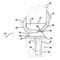
- FIG. 14is a perspective view of a posterior stabilized (PS) knee joint prosthesis according to the teachings of a fifth preferred embodiment of the present invention.
- PSposterior stabilized
- FIG. 15is an exploded perspective view of a tibial component and bearing element of the posterior stabilized (PS) knee joint prosthesis of FIG. 14;
- FIG. 16is a sagittal elevational view of the posterior stabilized (PS) knee joint prosthesis, shown in FIG. 14 with a tibia and a femur of the natural knee shown in phantom;
- PSposterior stabilized
- FIG. 17is a coronal elevational view of the posterior stabilized (PS) knee joint prosthesis shown in FIG. 14;
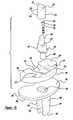
- FIG. 18is a sagittal sectional view of the posterior stabilized (PS) knee joint prosthesis of FIG. 14 taken about line 18 — 18 of FIG. 17;
- PSposterior stabilized
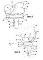
- FIG. 19is a top view of the assembled tibial component and bearing member of the posterior stabilized (PS) knee joint prosthesis of FIG. 14;
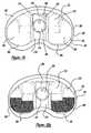
- FIGS. 20 a - 20 bare top views of the assembled tibial component and bearing member of FIG. 14 identifying shaded the contact areas in extension and flexion;
- FIG. 21is a top view of an assembled tibial component and bearing member according to the teachings of a sixth preferred embodiment of the present invention.
- FIG. 22is a top view of an assembled tibial component and bearing member according to the teachings of a seventh preferred embodiment of the present invention.
- FIGS. 23 a - 23 dare partial sagittal sectional views of the posterior stabilized (PS) knee joint prosthesis, shown in FIG. 14 illustrating four different positions of the femoral component with respect to the tibial component during a range of flexion from full extension to 110° of flexion.
- PSposterior stabilized
- the knee joint prosthesis 10is generally known as a posterior stabilized (PS) knee joint prosthesis 10 which is designed to provide adequate stability in case of moderate deterioration or instability of the human knee. This most typically occurs when the anterior and posterior cruciate ligaments are sacrificed or dysfunctional and the medial and lateral collateral ligaments remain functionally intact.
- PSposterior stabilized
- the knee joint prosthesis 10includes a femoral component 16 , a tibial component 18 and a floating tibial bearing 20 .
- the femoral component 16is adapted to be secured to a distal end of the femur 14 and includes a first condylar portion 22 and a second condylar portion 24 that provide a first femoral bearing surface 26 and a second femoral bearing surface 28 , respectively.
- the first and second condylar portions 22 and 24 of the femoral component 16are interconnected by an intercondylar portion 30 that defines an intercondylar recess 32 .
- the intercondylar portion 30includes a first lateral sidewall 34 and a second lateral sidewall 36 that are substantially planar and parallel to one another.
- the anterior portions of the first and second lateral sidewalls 34 and 36are connected by an anterior wall 38 and the posterior portions of the first and second lateral sidewalls 34 and 36 are connected by a posterior engagement member or elongated cam 40 .
- the intercondylar portion 30which includes the first and second lateral sidewalls 34 and 36 , the anterior wall 38 and the posterior engagement member 40 define the perimeter of a box 42 that defines the intercondylar recess 32 .
- the femoral component 16further includes an arcuate patellar portion 48 which is disposed on the anterior surface of the femoral component 16 .
- the patellar portion 48is shaped to allow anatomical tracking of a natural or prosthetic patella.
- the patella prostheses which are compatible with the present inventionmay be of varying shape, such as round or dome shaped and may be constructed from polyethylene, polyethylene with metal backing or other suitable materials.
- the femoral component 16 including the box 42is preferably formed as a unitary structure and preferably cast of a biocompatible high strength alloy, such as a cobalt-chromium-molybdenum alloy or other suitable material. All surfaces which do not contact the femur 14 are preferably highly polished to provide smooth articulating bearing surfaces.
- the tibial component 18is adapted to be secured to the proximal end of the tibial 12 after the tibia has been resected in a manner known in the art.
- the tibial component 18includes a substantially planar platform-like tibial tray 50 and an inferiorly extending tibial stem 52 .
- the tibial stem 52is adapted to be received in a corresponding opening made by the surgeon in the longitudinal center of the tibia 12 .
- the tibial tray 50 and the tibial stem 52define a conically shaped bore 54 axially extending through the tibial tray 50 and into the stem 52 .
- the tibial tray or plateau 50 and stem 52are preferably manufactured from cobalt-chromium-molybdenum or any other suitable biocompatible material.
- the top of the tibial tray 50is highly polished to provide a substantially smooth tibial bearing surface 56 .
- the floating or rotating bearing 20is located between the femoral component 16 and the tibial component 18 .
- the floating bearing 20has a substantially planar inferior bearing surface 58 which slidably moves relative to the highly polished tibial bearing surface 56 , further discussed herein.
- the floating bearing 20further includes a first superior articulating or bearing surface 59 and a second superior articulating or bearing surface 60 .
- the first bearing surface 59 and the second bearing surface 60articulate with the first bearing surface 26 of the condyle 22 and the second bearing surface 28 of the condyle 24 of the femoral component 16 .
- a substantially rectangular opening 62Positioned between the first and second bearing surfaces 59 and 60 is a substantially rectangular opening 62 that is slidably positioned about a center modular guide post 64 .
- the opening 62is defined by a substantially perpendicular peripheral sidewall 66 which is operable to engage the center guide post 64 .
- the floating bearing 20is preferably formed from a surgical grade, low friction, low wearing plastic, such as UHMWPE or other suitable material.
- the center guide post 64includes a substantially oval shaped outer peripheral sidewall 68 or any other appropriately shaped sidewall and a conically tapered sidewall 70 .
- the conically tapered sidewall 70is operable to be nestingly received within the conically tapered bore 54 to provide a friction fit that forms a Morse-type taper.
- the center guide post 64may be formed integral with the tibial component 18 .
- Extending axially through the center guide post 64is a substantially cylindrical bore 72 having a superiorly located counterbore 74 , as shown clearly in FIG. 5 a .
- the center guide post 64is formed from a combination of a cobalt-chromium-molybdenum portion 76 and a molded polymer portion 78 formed from UHMWPE or other suitable material.
- the polymer portion 78extends to the base of the tibial tray 50 to provide a polymer/polymer contact between the centering post 64 and the floating bearing 20 , via sidewalls 66 and 68 .
- Axially extending through the bore 72is a threaded bolt 80 which threadably engages a threaded bore 82 located inferiorly of the stem 52 .
- the bolt 80further includes a head 84 which is nestingly received within counterbore 74 .
- the head 84includes a hexagonal drive 86 that may be rotatably engaged by a hexagonal drive member.
- FIG. 5 ba second embodiment of a centering post 64 ′ is shown.
- the centering post 64 ′is substantially similar to the centering post 64 except that the metal portion 76 ′ extends above the tibial tray 50 , thereby providing a reduced or smaller polymer portion 78 ′.
- a polymer/metal contact or interfaceis formed between the floating bearing 20 and the centering post 64 ′, via the sidewalls 66 and 68 .
- each condyle 22 and 24 of the femoral component 16has a polycentric bearing surface 26 and 28 , respectively along the sagittal plane.
- each bearing surface 26 and 28is defined by a large anterior radius 80 and a smaller posterior/distal radius 82 .
- the large anterior radius 80is preferably about 1.497 inches and extends to about point 84 .
- the posterior/distal radius 82is about 0.945 inches and extends anterior the center line of the femoral component 16 up to point 84 .
- Point 84is located just anterior the floating bearing 20 .
- the bearing surface 59 and 60 of the floating bearing 20are formed with a single radius 86 along the sagittal plane having a radius of about 0.945 inches. Because the sagittal posterior/distal radius 82 of the femoral component 16 extends beyond the axial center line of the femoral component 16 anteriorly to point 84 , this radius congruently mates with the radius 86 of the floating bearing 20 from extension to full flexion. This mating provides a substantially fully mated and constant contact surface area between the femoral component 16 and the floating bearing 20 substantially through extension and flexion along the sagittal plane.
- Each bearing surface 26 and 28 of the condyles 22 and 24are arcuately shaped with a constant radius 88 of about 1.6 inches along the coronal plane.
- the bearing surfaces 59 and 60 of the floating bearing 20are likewise, formed from a constant radius 90 of about 1.6 inches along the coronal plane.
- Each of the radii 88 and 90congruently mate with one another to provide substantially full surface contact along the coronal plane from extension to flexion.
- This full surface contact along both the sagittal and coronal planessubstantially evenly disburses stresses between the femoral component 16 and the floating bearing 20 , as opposed to femoral components, which merely provide a smaller contact area, such as a line or point contact, either along the sagittal plane or the coronal plane which focuses stresses at these contact points, thereby potentially increasing wear in these areas.
- a contact area of greater than about 300 mm 2is maintained from extension to full flexion between the femoral component 16 and the floating bearing 20 .
- the floating bearing 20has an outer peripheral wall 92 which is substantially concentric with the outer peripheral wall 94 of the tibial tray 50 .
- the guide post 64is positioned just posteriorly the opening 62 defined by sidewall 66 . It should be noted that the post 64 is sized relative to the opening 62 such that the posterior stabilized knee joint prosthesis 10 provides anterior and posterior movement 96 , medial to lateral movement 98 , and rotation movement 100 of the floating bearing 20 relative to the tibial component 18 .
- the femoral component 16provides rotational movement along the sagittal plane relative to the floating bearing 20 , as well as varus and valgus movement relative to the floating bearing 20 .
- the posterior stabilized knee joint prosthesis 10may also simply provide the anterior to posterior movement 96 and the rotational movement 100 and eliminate the medial to lateral movement 98 of the floating bearing 20 relative to the tibial tray 50 .
- FIGS. 8 a - 8 epartial sagittal sectional views of the posterior stabilized (PS) knee joint prosthesis 10 illustrating the movement of the femoral component 16 and the floating bearing 20 relative to the tibial component 18 are shown from full extension in FIG. 8 a to full flexion in FIG. 8 e .
- the posterior stabilized (PS) knee joint prosthesis 10both anteriorly and posteriorly, is inherently stable at full extension when the patient is standing.
- the first and second femoral bearing surfaces 26 and 28are rested within the first and second tibial bearing surfaces 59 and 60 of the floating bearing 20 , respectively.
- the anterior surface 102 and the posterior surface 104 of the post 64do not engage the anterior portion 106 or the posterior portion 108 of the sidewall 66 .
- the posterior surface 104 of the post 64further does not engage the engagement member 40 of the femoral component 16 . If the knee joint prosthesis 10 would undergo a large hyper-extension or forward rollback (approximately 10°), the anterior surface 102 of the post 64 would engage the anterior portion 38 of box 42 in the femoral component 16 , while the floating bearing 20 would generally slide posteriorly relative to the tibial tray 50 . This engagement will further avoid posterior dislocation of the femoral component 16 relative to the tibial component 18 .
- the femoral component 16 with respect to the tibial component 18 and the floating bearing 20is generally most unrestricted between full extension, as illustrated in FIG. 8 a and the point of flexion where the posterior engagement member 40 and the posterior surface 104 of the post 64 initially engage, as illustrated in FIG. 8 b .
- This engagementgenerally occurs between about 20° to 45° of flexion.
- the femoral component 16is permitted to translate in the sagittal plane along with the floating bearing 20 relative to the tibial component 18 .
- the femoral component 16will remain substantially congruently positioned relative to the floating bearing 20 to provide a full articulating contact surface during this range of flexion.
- the femoral component 16 and the floating bearing 20are both able to move anteriorly and posteriorly relatively freely with respect to the tibial component 18 , via the bearing surfaces 56 and 58 between the floating bearing 20 and the tibial tray 50 .
- the exact amount of translation in the sagittal plane permitted by the knee joint prosthesis 10will of course, vary depending on the forces imparted by local soft tissues, muscles, tendons, ligaments, as well as forces transmitted from the tibia and fibula. These forces will, of course, vary from patient to patient, from activity to activity, as well as from implantation to implantation.
- the forced rollback provided by the engagement of the fixed modular post 64 with the engagement member 40enables a full surface contact area to be maintained between the femoral component 16 and the floating bearing 20 .
- This full surface contactis achieved because rollback is occurring between the floating bearing 20 and the tibial component 18 , via a sliding of the floating bearing 20 posteriorly atop the tibial tray 50 with surfaces 56 and 58 .
- Thisis in contrast to existing fixed bearing knee prostheses which achieve rollback, via the translation of the femoral component relative to a fixed bearing atop the tibial component.
- FIG. 9a top view of the tibial component 18 and the floating bearing 20 is shown with a fully constrained guide post 110 .
- the post 110is substantially similar to the post 64 , except that the outer peripheral wall 112 is oval with truncated ends 114 .
- the endwalls 114slidably engage the sidewalls 66 of opening 62 , thereby eliminating any lateral or medial movement 98 or rotational movement 100 with respect to the tibial component 18 .
- This fully constrained type kneetherefore, only allows anterior and posterior movement 96 of the floating bearing 20 relative to the tibial component 18 .
- the knee joint prosthesis 10may be converted from a posterior stabilized (PS) knee joint prosthesis 10 to a fully constrained knee joint prosthesis 10 ′.
- PSposterior stabilized
- Thisprovides for a fully constrained knee that maintains the large contact area (i.e. >300 mm 2 ), as well as having the desired rollback.
- the anterior motionmay be adjusted.
- removable sleevesmay be fashioned that slide on to post 64 to provide for further adjustment.
- This convertibilityenables a substantially convenient method for changing from a posterior stabilized (PS) to a fully constrained knee joint by simply replacing the guide post 64 , via the threaded bolt 80 .
- a closed box femoral component 16 ′may be used which includes a femoral stem 116 .
- the original femoral component 16would be replaced with the new femoral component 16 ′, while the tibial component 18 and the bearing component 20 would stay the same.
- the movement of the femoral component 16 , the tibial component 18 and bearing member 20 relative to one another along the sagittal planeis substantially similar to that shown in FIGS. 8 a - 8 e of the posterior stabilized (PS) knee joint prosthesis 10 .
- FIGS. 11 and 12a primary knee joint prosthesis 120 according to the teachings of a third preferred embodiment of the present invention is shown.
- the tibial component 18 and the floating bearing 20are substantially the same as used with the other preferred embodiments.
- the post 124is substantially similar to the post 64 except that the height of the post is reduced so that it does not extend above or out beyond the opening 62 .
- the femoral component 122includes the first and second condyles 22 and 24 having the first and second bearing surfaces 26 and 28 , respectively.
- the femoral component 122further includes the articulating patella portion 48 .
- the rollback of the floating bearing 20is achieved by the remaining soft tissues and ligaments of the patient.
- the floating bearing 20is initially centrally positioned about the tibial tray 50 similar to the other preferred embodiments during full extension. At about 25° to 45° of flexion, rollback of the floating bearing 20 starts and is substantially maintained through full flexion because of the cruciate ligament causing the floating bearing 20 to roll back.
- the primary knee joint prosthesis 120may be converted from a primary knee joint prosthesis 120 to a posterior stabilized (PS) knee joint prosthesis 10 or a fully constrained knee joint prosthesis 10 ′ by simply replacing the post 124 and the femoral component 122 without having to change the tibial component 18 or the tibial bearing 20 .
- PSposterior stabilized
- FIG. 13a partial sagittal sectional view of a posterior stabilized (PS) knee joint prosthesis 10 ′′ according to the teachings of a fourth preferred embodiment of the present invention is shown.
- PSposterior stabilized
- FIG. 13a partial sagittal sectional view of a posterior stabilized (PS) knee joint prosthesis 10 ′′ according to the teachings of a fourth preferred embodiment of the present invention is shown.
- the guide post 130is secured to the tibial component 18 in substantially the same manner as that shown with regard to the knee joint prosthesis 10 .
- the difference in the guide post 130is that it includes a first guide portion 134 and a second guide portion 136 .
- the first guide portion 134is defined by a substantially oval shaped sidewall 138 similar to that shown in FIG.
- the second guide portion 136is also formed by an oval sidewall 140 which is larger than the oval sidewall 138 .
- the first guide portion 134is preferably formed from a molded polymer, such as UHMWPE and the second guide portion 136 is preferably formed from a cobalt-chromium-molybdenum.
- various other combinations between the first guide portion 134 and the second guide portion 136can also be provided such as a complete polymer assembly, complete metallic assembly or any other combination.
- the second guide portion 136has a height which does not extend beyond the bearing 134 and is positioned within opening 142 such that the second guide portion 136 only engages and controls the movement of the floating bearing 132 relative to the tibial component 18 .
- the second guide portion 134extends into the box 42 of the femoral component 16 such that the second guide portion 134 is operable to be engaged by the cam member 40 to control the movement of the femoral component 16 relative to the bearing 132 .
- the two stage guide post 138individually controls the relative movement of the femoral component 16 and the bearing component 132 with the first guide portion 134 and the second guide portion 136 , respectively. This provides for increased adjustability in the relative articulating motion of the knee joint prosthesis 10 ′′ while further maintaining a substantially full and continuous contact area between the femoral component 16 and the floating bearing 132 from extension to full flexion.
- FIGS. 14-20there is shown a posterior stabilized (PS) knee joint prosthesis 146 according to the teachings of a fifth preferred embodiment of the present invention which is designed to provide adequate stability in case of moderate deterioration or instability of the human knee.
- the knee joint prosthesis 146is shown in FIG. 16 as being secured to a tibia 148 and a femur 150 of a surgically resected left knee joint, with the tibia 148 and the femur 150 shown in phantom, and with the understanding that a suitable right knee joint prosthesis can be similarly constructed.
- the knee joint prosthesis 146includes a femoral component 152 , a tibial component 154 and a floating tibial bearing 156 .
- the femoral component 152is adapted to be secured to the distal end of the femur 150 similar to the femoral component 16 , shown in FIG. 1 .
- the femoral component 152includes a first condylar portion 158 and a second condylar portion 160 that provides a first femoral bearing surface 162 and a second femoral bearing surface 164 , respectively (see FIG. 17 ).
- the first and second condylar portions 158 and 160are inter-connected by an inner condylar portion 166 that defines an inner condylar recess 168 .
- the inner condylar portion 166is defined by first and second lateral sidewalls 170 and 172 , anterior wall 174 , posterior engagement member or cam 176 and top 178 .
- the top 178may either be an open or closed top, depending upon the desired configuration.
- the femoral component 152also includes an arcuate patellar portion 180 which is disposed on the anterior surface of the femoral component 152 .
- the patellar portion 180is shaped to allow anatomical tracking of a natural or prosthetic patella.
- the patella prosthesiswhich are compatible with the present invention may be of varying shapes, such as round or dome shaped and may be constructed from polyethylene, polyethylene with metal backing or other suitable materials.
- the femoral component 152is preferably formed as a unitary structure and cast from a biocompatible high strength alloy, such as cobalt-chromium-molybdenum alloy or other suitable biocompatible material.
- the surfaces which do not contact the femur 150are preferably highly polished to provide smooth articulating bearing surfaces.
- the tibial component 154is substantially similar to the tibial component 18 and is likewise adapted to be secured to the proximal end of the tibial 148 after the tibia 148 has been resected in a manner known in the art.
- the tibial component 154includes a substantially planar platform-like tibial tray 182 and an inferiorly extending tibial stem 184 .
- the tibial stem 184is adapted to be received in a corresponding opening made by a surgeon in the longitudinal center of the tibia 148 .
- the tibial stem 184is formed from a first planar member 186 , which is positioned substantially perpendicular to the tibial plateau 182 and a second planar member 188 which is positioned at a slight angle relative to the perpendicular axis of member 186 .
- Connecting member 186 with member 188is a tapered member 190 , which tapers at its distal end 192 to form a substantially I-beam cross-section.
- the tibial tray 182 and the tibial stem 184define a conically shaped bore 194 .
- the tibial tray 182 and the tibial stem 184are preferably manufactured from cobalt-chromium-molybdenum, or any other suitable material with the top of the tibial tray 182 being highly polished to provide a substantially smooth tibial bearing surface 196 .
- the floating bearing 156is positioned between the femoral component 152 and the tibial component 154 .
- the floating bearing 156includes a substantially planar inferior bearing surface 198 which slidably moves relative to the highly polished tibial bearing surface 196 .
- the floating bearing 156also includes a first superior articulating or bearing surface 200 and a second superior articulating or bearing surface 202 . Positioned between the first and second bearing surfaces 200 and 202 is an elongated opening 204 that is slidably positioned about a guide post 206 .
- the opening 204is defined by a pair of opposed lateral sidewalls 208 , a semi-circular or arcuate posterior sidewall 210 and an anterior sidewall 212 which has a pair of recessed lobes or ears 214 . Extending posteriorly from the opening 204 is a recessed area 216 positioned or located between the first bearing surface 200 and the second bearing surface 202 .
- the floating bearing 156is also preferably formed from a surgical grade, low friction, low wearing plastic, such as UHMWPE or other suitable material.
- the center guide post 206includes a substantially cylindrically shaped outer peripheral sidewall 218 and a conically tapered sidewall 220 .
- the conically tapered sidewall 220is operable to be nestingly received within the conically tapered bore 194 to provide a friction fit formed by a Morse-type taper.
- guide post 206may also be formed integral with the tibial component 154 .
- the guide post 206is constructed from a combination of a cobalt-chromium-molybdenum portion 222 and a molded polymer portion 224 formed from UHMWPE or other suitable material.
- the non-polymer portion 222extends up to the floating bearing 156 so that the floating bearing 156 contacts the cobalt-chromium-molybdenum cylindrical sidewall 218 .
- the polymer portion 224is molded to a post 226 and extends from above the floating bearing 156 into the recess 168 , also having the outer cylindrical sidewall 218 .
- the superior surface of the guide post 206has an anterior arcuate surface 228 and planar tapered superior sidewalls 230 .
- the anterior arcuate sidewall 228reduces or eliminates impingement of the post 206 within the inner condylar portion 166 during hyper-extension of the knee joint prosthesis 146 .
- the cylindrical sidewall 218also includes a posterior planar sidewall portion 231 , further discussed herein.
- Extending through the center guide post 206is a substantially cylindrical axial bore 232 having a stepped shoulder 234 .
- the stepped shoulder 234forms a retention mechanism to retain a threaded bolt 236 within the axial bore 232 .
- the non-polymer portion 222 of the guide post 206is machined and tooled in the configuration shown.
- the threaded bolt 236which includes a head 238 having a hexagonal drive 240 is then inserted into the bore 232 . Thereafter, the polymer portion 224 is molded over the elongated post 226 with the subsequent bore 232 being formed therein to create the shoulder 234 .
- the shoulder 234captures or retains the bolt 236 within the non-polymer portion 222 of the center guide post 206 . In this way, should the bolt 236 ever become loosened from threaded bore 242 , it will not be free to enter the articulating area of the knee joint prosthesis 146 .
- the tapered sidewall 220is matingly received within the tapered bore 194 and the bolt 236 is threadably engaged within bore 242 to securely hold the centering guide post 206 relative to the tibial component 154 .
- FIG. 21another embodiment of a centering post 244 is shown.
- the centering post 244is substantially similar to the centering post 206 , except that the non-polymer portion 222 of the cylindrical sidewall 218 includes a pair of arcuate lobes or ears 246 which extend anteriorly from the post 244 .
- the arcuate lobes 246extend anteriorly in the region of the floating bearing 146 and do not extend up beyond this region into the recess 168 of the femoral component 152 , thereby providing two guide portions or regions in the guide post 244 .
- the guide post 244also includes a posterior planar sidewall 248 extending throughout the length of the sidewall 218 .
- This planar sidewall region 248inhibits contact of the post 244 relative to the posterior sidewall 210 of the opening 204 formed within the bearing 156 .
- thisdisburses the force imparted by the post 244 to the thickest regions of the bearing 156 , thereby enhancing distribution of the engagement force between the post 244 and the bearing 156 .
- the guide post 244enables the bearing 156 to move anterior-posterior (A-P), as well as enables rotational movement of the bearing 156 relative to the tibial component 154 , similar to the guide post 206 .
- A-Panterior-posterior
- rotational movementis substantially limited to about +/ ⁇ 15°.
- the lateral sidewall 208 of the opening 204will engage one of the arcuate lobes 246 upon rotation of about 15°, thereby preventing further rotation of the bearing member 156 relative to the guide post 244 .
- Thisprovides a more constrained knee joint prosthesis 146 as compared to the guide post 206 . Therefore, by simply switching the guide post 206 with the guide post 244 , the rotational translation of the knee joint prosthesis 146 can be changed or constrained to about +/ ⁇ 15°, while still providing the same A-P translation.
- a guide post 244 ′is shown in use with the bearing 156 having a different shaped opening 250 .
- the opening 250includes an anterior sidewall 252 , a posterior sidewall 254 and a pair of angled lateral sidewalls 256 .
- the angled lateral sidewalls 256narrow the opening 250 posteriorly and widen the opening 250 anteriorly.
- the guide post 244 ′somewhat engages the posterior sidewall 254 with the arcuate lobes 246 substantially aligning with the angled lateral sidewalls 256 , such that there is little or no rotation of the bearing 156 relative to the post 244 ′ in extension.
- the bearing 156is forced posteriorly, further discussed herein, such that the guide post 244 ′ enters the widened recessed area between the lateral sidewalls 256 .
- the bearing 156is forced further posteriorly, further rotational freedom of movement is provided for the bearing 156 relative to the guide post 244 ′, as well as medial to lateral movement during this A-P translation, thereby providing a less constrained knee joint prosthesis 146 with increased flexion.
- This type of constraintclosely mimics an anatomical knee joint. Therefore, by simply changing the style bearing component or opening formed within the bearing 156 , varying constraint may be achieved.
- each condyle 158 and 160 of the femoral component 152has a polycentric bearing surface 162 and 164 , respectively along the sagittal plane.
- each bearing surface 162 and 164is defined by a large anterior radius 260 and a smaller posterior/distal radius 262 .
- Point 264is located just anterior the contact area of the floating bearing 156 .
- the bearing surfaces 200 and 202 of the floating bearing 156are formed with a single radius along the sagittal plane that corresponds to the posterior/distal radius 262 .
- the posterior radius 262 of the condyles 158 and 160extends up to point 264 cutting into a region of the condyles 158 and 160 to form a pair of opened anterior cavities or regions 268 .
- These opened cavities 268are positioned above the contact areas of the floating bearing 156 in extension and engage stop regions 270 of the floating bearing 156 during hyper-extension.
- the bearing 156further includes inner regions 272 which engage the inner regions 274 of the condyles 158 and 160 only during hyper-extension.
- the opened anterior cavities 268are positioned above the stops 270 to eliminate conformity in this region, thereby substantially reducing soft tissue impingement in this area.
- Contact between the stop region 270 and the anterior cavities 268only occur during hyper-extension of the knee joint prosthesis 146 .
- Each bearing surface 162 and 164 of the condyles 158 and 160are also arcuately shaped with a constant radius 276 , along the coronal plane.
- the bearing surfaces 200 and 202 of the floating bearing 156are likewise, formed from a similar constant radius 278 along the coronal plane of the floating bearing 156 .
- Each of the radii 276 and 278congruently mate with one another to provide a large surface contact area along the coronal plane which increases as flexion increases.
- FIGS. 20 a and 20 bthe contact area on the floating bearing 156 with the condyle bearing surfaces 162 and 164 in extension are shown shaded in FIG. 20 a .
- the floating bearing 156has an outer peripheral wall 280 which is substantially concentric with the outer peripheral wall 282 of the tibial tray 182 .
- the outer peripheral wall 280 of the floating bearing 156also includes a pair of posterior lip extensions 284 which extend out along the bearing surface 198 of the floating bearing 156 (see FIG. 18 ). This pair of lip extensions 284 eliminates undesirable moment arms as the femoral component 152 moves posterior and rolls up the posterior portion of the center guide post 206 during extreme flexion (see FIG. 23 d ).
- the floating bearing 156is substantially inhibited from tilting superiorly based upon the moment arms generated upon such flexion.
- the guide post 206is positioned substantially posteriorly of the opening 204 , such that the posterior stabilized knee joint prosthesis 146 provides anterior and posterior movement and rotational movement of the floating bearing 156 relative to the tibial component 154 . Also the femoral component 152 provides rotational movement along the sagittal plane relative to the floating bearing 156 , as well as varus and valgus movement relative to the floating bearing surface 156 . It should further be noted that by simply changing the post configuration or the opening configuration, various types of constraints may be easily accommodated.
- FIGS. 23 a - 23 dpartial sagittal sectional views of the posterior stabilized (PS) knee joint prosthesis 146 illustrating the movement of the femoral component 152 and the floating bearing 156 relative to the tibial component 154 are shown from extension in FIG. 23 a to flexion of 110° in FIG. 23 d .
- the posterior stabilized (PS) knee joint prosthesis 146both anteriorly and posteriorly, is inherently stable at full extension when the patient is standing.
- the first and second femoral bearing surfaces 162 and 164are nested within the first and second tibial bearing surfaces 200 and 202 of the floating bearing 156 , respectively.
- the stop portions 270are not in contact with the anterior cavities 268 in the femoral component 152 to inhibit soft tissue impingement in this region during extension.
- the anterior surface 286 and the posterior surface 288 of the guide post 206is generally not in engagement with the anterior sidewall 212 or the posterior sidewall 210 of the opening 204 or with the posterior cam 176 or the anterior wall 174 of the inner condylar portion 166 .
- the anterior surface 286 of the guide post 206would engage the anterior sidewall 174 of the inner condylar portion 166 .
- the pair of anterior cavities 268 of the femoral component 152would also engage the stops 270 of the bearing 156 , while the inner condylar bearing surfaces 274 would engage the inner surfaces 272 of the floating bearing 156 . This engagement will avoid posterior dislocation of the femoral component 152 relative to the tibial component 154 .
- the posterior cam 176will generally engage the posterior side 288 of the post 206 at about 40° of flexion, as shown in FIG. 23 b .
- the femoral component 152 , the tibial component 154 and the floating bearing 156is generally most unrestricted, such that the femoral component 152 is permitted to translate in the sagittal plane along with the floating bearing 156 relative to the tibial component 154 .
- the floating bearing 156rolls back posteriorly relative to the tibial tray 182 .
- a forced rollback of the floating bearing 156 relative to the tibial tray 182continues to occur while the contact area between the femoral component and floating bearing increases as shown in FIG. 20 b .
- the femoral component 156moves posteriorly and rolls up upon the posterior side 288 of the guide post 206 reducing the contact area between the femoral component 152 and the bearing 156 .
- the posterior lip extension 284prevent the floating bearing 156 from flipping up or tipping superiorly during this phase of flexion by reducing the moment arm about the contact point of the posterior cam 176 to the contact surface between the femoral component 152 and the floating bearing 156 .
- forced rollbackprovided by the engagement of the fixed modular guide post 206 with the cam 176 provides a surface contact area between the femoral component 152 and the floating bearing 156 which increases as flexion increases (see FIGS. 20 a - 20 b ), until extreme flexion (i.e., ⁇ 110°).
- extreme flexioni.e., ⁇ 110°.
- wear on the guide post 206is substantially reduced because the post/cam contact occurs after the loading phase of normal gait.
- the cam 176contacts the guide post 206 closer to the tibial/femoral articulation or lower along the guide post 206 .
- This lower contact pointreduces the moment arm on the guide post 206 , and therefore, the stresses on the guide post 206 .
- the guide post 206maintains the position of the bearing 156 from 0° to 40° of flexion since tibial or femoral congruency is maintained and the bearing cannot slide forward with the posterior surface of the opening, engaging the posterior side 288 of the post 206 .
Landscapes
- Health & Medical Sciences (AREA)
- Orthopedic Medicine & Surgery (AREA)
- Physical Education & Sports Medicine (AREA)
- Cardiology (AREA)
- Oral & Maxillofacial Surgery (AREA)
- Transplantation (AREA)
- Engineering & Computer Science (AREA)
- Biomedical Technology (AREA)
- Heart & Thoracic Surgery (AREA)
- Vascular Medicine (AREA)
- Life Sciences & Earth Sciences (AREA)
- Animal Behavior & Ethology (AREA)
- General Health & Medical Sciences (AREA)
- Public Health (AREA)
- Veterinary Medicine (AREA)
- Prostheses (AREA)
Abstract
Description
Claims (20)
Priority Applications (6)
| Application Number | Priority Date | Filing Date | Title |
|---|---|---|---|
| US09/695,448US6413279B1 (en) | 1999-03-01 | 2000-10-24 | Floating bearing knee joint prosthesis with a fixed tibial post |
| AU2002220026AAU2002220026A1 (en) | 2000-10-24 | 2001-10-24 | Floating bearing knee joint prosthesis with a fixed tibial post |
| EP01988560AEP1333785B1 (en) | 2000-10-24 | 2001-10-24 | Floating bearing knee joint prosthesis with a fixed tibial post |
| PCT/US2001/045264WO2002034156A2 (en) | 2000-10-24 | 2001-10-24 | Floating bearing knee joint prosthesis with a fixed tibial post |
| AT01988560TATE539712T1 (en) | 2000-10-24 | 2001-10-24 | FLOATING SUPPORT KNEE JOINT PROSTHESIS WITH FIXED TIBIAL POST |
| US10/188,305US6972039B2 (en) | 1999-03-01 | 2002-07-01 | Floating bearing knee joint prosthesis with a fixed tibial post |
Applications Claiming Priority (2)
| Application Number | Priority Date | Filing Date | Title |
|---|---|---|---|
| US09/259,873US6165223A (en) | 1999-03-01 | 1999-03-01 | Floating bearing knee joint prosthesis with a fixed tibial post |
| US09/695,448US6413279B1 (en) | 1999-03-01 | 2000-10-24 | Floating bearing knee joint prosthesis with a fixed tibial post |
Related Parent Applications (1)
| Application Number | Title | Priority Date | Filing Date |
|---|---|---|---|
| US09/259,873Continuation-In-PartUS6165223A (en) | 1999-03-01 | 1999-03-01 | Floating bearing knee joint prosthesis with a fixed tibial post |
Related Child Applications (1)
| Application Number | Title | Priority Date | Filing Date |
|---|---|---|---|
| US10/188,305Continuation-In-PartUS6972039B2 (en) | 1999-03-01 | 2002-07-01 | Floating bearing knee joint prosthesis with a fixed tibial post |
Publications (1)
| Publication Number | Publication Date |
|---|---|
| US6413279B1true US6413279B1 (en) | 2002-07-02 |
Family
ID=24793008
Family Applications (1)
| Application Number | Title | Priority Date | Filing Date |
|---|---|---|---|
| US09/695,448Expired - LifetimeUS6413279B1 (en) | 1999-03-01 | 2000-10-24 | Floating bearing knee joint prosthesis with a fixed tibial post |
Country Status (5)
| Country | Link |
|---|---|
| US (1) | US6413279B1 (en) |
| EP (1) | EP1333785B1 (en) |
| AT (1) | ATE539712T1 (en) |
| AU (1) | AU2002220026A1 (en) |
| WO (1) | WO2002034156A2 (en) |
Cited By (119)
| Publication number | Priority date | Publication date | Assignee | Title |
|---|---|---|---|---|
| US20030006530A1 (en)* | 2001-06-29 | 2003-01-09 | Gundlapalli Rama Rao V. | Joint prosthesis molding method and die for preforming the same |
| US20030153979A1 (en)* | 2002-02-11 | 2003-08-14 | Dean Hughes | Posterior stabilized knee system prosthetic devices employing diffusion-hardened surfaces |
| US20030163201A1 (en)* | 2002-02-26 | 2003-08-28 | Mcminn Derek James Wallace | Knee prosthesis |
| FR2844704A1 (en)* | 2002-09-24 | 2004-03-26 | Biomet Merck France | Mobile plate knee prosthesis comprises tibial base fixed on tibia upper end, intermediate friction plate received on tibia base having projection engaged in plate opening and femoral element anchored at femur lower end |
| US20040186583A1 (en)* | 2001-04-25 | 2004-09-23 | Arnold Keller | Knee prosthesis with rotation bearing |
| US20040199249A1 (en)* | 1999-05-10 | 2004-10-07 | Fell Barry M. | Surgically implantable knee prosthesis |
| US20040199250A1 (en)* | 1999-05-10 | 2004-10-07 | Fell Barry M. | Surgically implantable knee prosthesis |
| US20040225368A1 (en)* | 2003-04-24 | 2004-11-11 | Sylvie Plumet | Modular stud for posterior stabilised knee prosthesis |
| US20040243244A1 (en)* | 2002-12-20 | 2004-12-02 | Jason Otto | High performance knee prostheses |
| US20040267363A1 (en)* | 1999-05-10 | 2004-12-30 | Fell Barry M | Surgically implantable knee prosthesis |
| US20050033424A1 (en)* | 1999-05-10 | 2005-02-10 | Fell Barry M. | Surgically implantable knee prosthesis |
| US20050049711A1 (en)* | 2003-09-03 | 2005-03-03 | Ball Robert J. | Modular total ankle prosthesis apparatuses and methods |
| US20050171604A1 (en)* | 2004-01-20 | 2005-08-04 | Alexander Michalow | Unicondylar knee implant |
| US20050203632A1 (en)* | 2004-03-09 | 2005-09-15 | Daniels Michael E. | Tibial implant with a through post |
| US20050203629A1 (en)* | 2004-02-26 | 2005-09-15 | George Cipolletti | Modular knee prosthesis |
| US20050209702A1 (en)* | 2004-03-09 | 2005-09-22 | Todd Dwight T | Tibial knee component with a mobile bearing |
| US20050209703A1 (en)* | 1999-04-02 | 2005-09-22 | Fell Barry M | Surgically implantable prosthetic system |
| EP1604623A1 (en)* | 2004-06-11 | 2005-12-14 | Depuy Products, Inc. | Posterior stabilized mobile bearing knee |
| US20050283251A1 (en)* | 2002-02-20 | 2005-12-22 | Coon Thomas M | Knee arthroplasty prosthesis and method |
| US20060030944A1 (en)* | 2004-01-14 | 2006-02-09 | Haines Timothy G | Methods and apparatus for enhanced retention of prosthetic implants |
| US20060100714A1 (en)* | 2003-04-02 | 2006-05-11 | Ortho Development Corporation | Tibial augment connector |
| US20060142870A1 (en)* | 2004-08-19 | 2006-06-29 | Shawn Robinson | Modular total ankle prosthesis apparatuses, systems and methods, and systems and methods for bone resection and prosthetic implantation |
| US20060173547A1 (en)* | 2003-12-08 | 2006-08-03 | Ensign Michael D | Modular femoral knee stem extender |
| GB2426200A (en)* | 2005-05-19 | 2006-11-22 | Derek James Wallace Mcminn | Femoral component of knee prosthesis |
| US20060265080A1 (en)* | 2005-05-19 | 2006-11-23 | Mcminn Derek J W | Knee prosthesis |
| US20070135926A1 (en)* | 2005-12-14 | 2007-06-14 | Peter Walker | Surface guided knee replacement |
| US20070150067A1 (en)* | 2005-12-27 | 2007-06-28 | Howmedica Osteonics Corp. | Hybrid femoral implant |
| US20080033501A1 (en)* | 2005-07-25 | 2008-02-07 | Yossi Gross | Elliptical element for blood pressure reduction |
| US20080140212A1 (en)* | 2001-05-15 | 2008-06-12 | Robert Metzger | Elongated femoral component |
| US20080183177A1 (en)* | 2005-06-09 | 2008-07-31 | Biomet Manufacturing Corp. | Instrumentation And Method For Implanting A Curved Stem Tibial Tray |
| US20080188943A1 (en)* | 2001-06-30 | 2008-08-07 | Gundlapalli Rama Rao V | Prosthetic bearing with encapsulated reinforcement |
| US20080243258A1 (en)* | 2005-08-24 | 2008-10-02 | Kantilal Hastimal Sancheti | Knee Joint Prosthesis |
| US20080288080A1 (en)* | 2005-08-24 | 2008-11-20 | Kantilal Hastimal Sancheti | Knee joint prosthesis |
| US20080306605A1 (en)* | 2006-01-20 | 2008-12-11 | Hasselman Carl T | Method of Preparing an Ankle Joint for Replacement, Joint Prosthesis, and Cutting Alignmnet Apparatus for Use in Performing an Arthroplasty Procedure |
| US20090036992A1 (en)* | 2006-04-07 | 2009-02-05 | Athanasios Tsakonas | Total Knee Arthroplasty Endoprothesis with Third Condyle and Rotating Polyethylene Insert |
| US20090062924A1 (en)* | 2004-05-06 | 2009-03-05 | Biomet Manufacturing Corp. | Knee joint prosthesis |
| EP2042132A1 (en) | 2007-09-27 | 2009-04-01 | Finsbury (Development) Limited | Tibial prosthesis comprising a mobile bearing |
| US20090204221A1 (en)* | 2008-02-11 | 2009-08-13 | Peter Stanley Walker | Knee joint with a ramp |
| US7708741B1 (en) | 2001-08-28 | 2010-05-04 | Marctec, Llc | Method of preparing bones for knee replacement surgery |
| US7749229B1 (en) | 2000-01-14 | 2010-07-06 | Marctec, Llc | Total knee arthroplasty through shortened incision |
| WO2010093902A1 (en) | 2009-02-13 | 2010-08-19 | Biomet Manufacturing Corp. | Method and apparatus for manufacturing an implant |
| US7799084B2 (en) | 2002-10-23 | 2010-09-21 | Mako Surgical Corp. | Modular femoral component for a total knee joint replacement for minimally invasive implantation |
| WO2010144705A1 (en) | 2009-06-12 | 2010-12-16 | Biomet Manufacturing Corp. | Method and apparatus for manufacturing an implant |
| US20110040387A1 (en)* | 2009-08-11 | 2011-02-17 | IMDS, Inc. | Systems and methods for mobile bearing prosthetic knee |
| US20110066247A1 (en)* | 2009-08-11 | 2011-03-17 | Michael D. Ries | Position Adjustable Trial Systems for Prosthetic Implants |
| US20110066246A1 (en)* | 2009-08-11 | 2011-03-17 | Michael D. Ries | Articulating Trials for Prosthetic Implants |
| US20110066248A1 (en)* | 2009-08-11 | 2011-03-17 | Michael D. Ries | Position Adjustable Trial Systems for Prosthetic Implants |
| US7935151B2 (en) | 2001-03-05 | 2011-05-03 | Hudson Surgical Design, Inc. | Femoral prosthetic implant |
| US20110106265A1 (en)* | 2007-11-02 | 2011-05-05 | Biomet Uk Limited | Prosthesis for simulating natural kinematics |
| US20110125275A1 (en)* | 2009-11-16 | 2011-05-26 | New York Society For The Ruptured And Crippled Maintaining The Hospital For Special Surgery | Prosthetic condylar joints with articulating bearing surfaces having a translating contact point during rotation thereof |
| US20110125279A1 (en)* | 2009-11-16 | 2011-05-26 | New York Society For The Ruptured And Crippled Maintaining The Hospital For Special Surgery | Constrained condylar knee device |
| US7959635B1 (en) | 2000-01-14 | 2011-06-14 | Marctec, Llc. | Limited incision total joint replacement methods |
| US7967822B2 (en) | 1994-09-02 | 2011-06-28 | Hudson Surgical Design, Inc. | Methods and apparatus for orthopedic implants |
| US20110184525A1 (en)* | 2010-01-13 | 2011-07-28 | Aesculap Ag | Knee joint endoprosthesis |
| US20110202139A1 (en)* | 2010-02-18 | 2011-08-18 | Biomet Manufacturing Corp. | Prosthetic device with damper |
| US20110208316A1 (en)* | 2010-02-19 | 2011-08-25 | Biomet Manufacturing Corp. | Latent mobile bearing for prosthetic device |
| WO2011109260A1 (en) | 2010-03-05 | 2011-09-09 | Biomet Manufacturing Corp. | Method and apparatus for manufacturing an implant |
| US8021368B2 (en) | 2004-01-14 | 2011-09-20 | Hudson Surgical Design, Inc. | Methods and apparatus for improved cutting tools for resection |
| US20110313534A1 (en)* | 2009-08-11 | 2011-12-22 | Medicinelodge, Inc. Dba Imds Co-Innovation | Systems and methods for prosthetic knee |
| US8114083B2 (en) | 2004-01-14 | 2012-02-14 | Hudson Surgical Design, Inc. | Methods and apparatus for improved drilling and milling tools for resection |
| WO2012034033A1 (en)* | 2010-09-10 | 2012-03-15 | Zimmer, Inc. | Motion facilitating tibial components for a knee prosthesis |
| US8157869B2 (en) | 2007-01-10 | 2012-04-17 | Biomet Manufacturing Corp. | Knee joint prosthesis system and method for implantation |
| US8163028B2 (en) | 2007-01-10 | 2012-04-24 | Biomet Manufacturing Corp. | Knee joint prosthesis system and method for implantation |
| US8187280B2 (en) | 2007-10-10 | 2012-05-29 | Biomet Manufacturing Corp. | Knee joint prosthesis system and method for implantation |
| US8308794B2 (en) | 2004-11-15 | 2012-11-13 | IZEK Technologies, Inc. | Instrumented implantable stents, vascular grafts and other medical devices |
| US8328873B2 (en) | 2007-01-10 | 2012-12-11 | Biomet Manufacturing Corp. | Knee joint prosthesis system and method for implantation |
| US8491572B2 (en) | 2004-11-15 | 2013-07-23 | Izex Technologies, Inc. | Instrumented orthopedic and other medical implants |
| US8491661B2 (en) | 2010-10-05 | 2013-07-23 | Aesculap Ag | Knee joint prosthesis |
| US8496666B2 (en) | 2009-08-11 | 2013-07-30 | Imds Corporation | Instrumentation for mobile bearing prosthetics |
| US8562616B2 (en) | 2007-10-10 | 2013-10-22 | Biomet Manufacturing, Llc | Knee joint prosthesis system and method for implantation |
| US8568486B2 (en) | 2010-07-24 | 2013-10-29 | Zimmer, Inc. | Asymmetric tibial components for a knee prosthesis |
| US8603095B2 (en) | 1994-09-02 | 2013-12-10 | Puget Bio Ventures LLC | Apparatuses for femoral and tibial resection |
| US8628580B2 (en) | 2010-07-24 | 2014-01-14 | Zimmer, Inc. | Tibial prosthesis |
| US8678979B2 (en) | 1998-09-01 | 2014-03-25 | Izex Technologies, Inc. | Remote monitoring of a patient |
| US8734523B2 (en) | 2012-05-31 | 2014-05-27 | Howmedica Osteonics Corp. | Limited motion tibial bearing |
| US8740906B2 (en) | 2004-01-14 | 2014-06-03 | Hudson Surgical Design, Inc. | Method and apparatus for wireplasty bone resection |
| US8758444B2 (en) | 2011-11-21 | 2014-06-24 | Zimmer, Inc. | Tibial baseplate with asymmetric placement of fixation structures |
| US8900316B2 (en) | 2010-01-29 | 2014-12-02 | Smith & Nephew, Inc. | Cruciate-retaining knee prosthesis |
| US8926709B2 (en) | 2010-08-12 | 2015-01-06 | Smith & Nephew, Inc. | Structures for use in orthopaedic implant fixation and methods of installation onto a bone |
| US8998997B2 (en) | 2009-08-11 | 2015-04-07 | Michael D. Ries | Implantable mobile bearing prosthetics |
| US9155626B2 (en) | 2012-09-10 | 2015-10-13 | Acumed Llc | Radial head prosthesis with floating articular member |
| US9381090B2 (en) | 2010-07-24 | 2016-07-05 | Zimmer, Inc. | Asymmetric tibial components for a knee prosthesis |
| US9439659B2 (en) | 2011-08-31 | 2016-09-13 | Biomet Manufacturing, Llc | Patient-specific sacroiliac guides and associated methods |
| US9480490B2 (en) | 2006-02-27 | 2016-11-01 | Biomet Manufacturing, Llc | Patient-specific guides |
| US9480580B2 (en) | 2006-02-27 | 2016-11-01 | Biomet Manufacturing, Llc | Patient-specific acetabular alignment guides |
| US9522010B2 (en) | 2006-02-27 | 2016-12-20 | Biomet Manufacturing, Llc | Patient-specific orthopedic instruments |
| US9539013B2 (en) | 2006-02-27 | 2017-01-10 | Biomet Manufacturing, Llc | Patient-specific elbow guides and associated methods |
| US9642711B2 (en) | 2003-10-17 | 2017-05-09 | Smith & Nephew, Inc. | High flexion articular insert |
| US9662216B2 (en) | 2006-02-27 | 2017-05-30 | Biomet Manufacturing, Llc | Patient-specific hip joint devices |
| US9662127B2 (en) | 2006-02-27 | 2017-05-30 | Biomet Manufacturing, Llc | Patient-specific acetabular guides and associated instruments |
| US9730799B2 (en) | 2006-06-30 | 2017-08-15 | Smith & Nephew, Inc. | Anatomical motion hinged prosthesis |
| US9743935B2 (en) | 2011-03-07 | 2017-08-29 | Biomet Manufacturing, Llc | Patient-specific femoral version guide |
| US9763792B2 (en) | 2015-10-01 | 2017-09-19 | Acumed Llc | Radial head prosthesis with rotate-to-lock interface |
| US9795399B2 (en) | 2006-06-09 | 2017-10-24 | Biomet Manufacturing, Llc | Patient-specific knee alignment guide and associated method |
| US9820868B2 (en) | 2015-03-30 | 2017-11-21 | Biomet Manufacturing, Llc | Method and apparatus for a pin apparatus |
| US9861387B2 (en) | 2006-06-09 | 2018-01-09 | Biomet Manufacturing, Llc | Patient-specific knee alignment guide and associated method |
| US9918740B2 (en) | 2006-02-27 | 2018-03-20 | Biomet Manufacturing, Llc | Backup surgical instrument system and method |
| US9968376B2 (en) | 2010-11-29 | 2018-05-15 | Biomet Manufacturing, Llc | Patient-specific orthopedic instruments |
| US9993344B2 (en) | 2006-06-09 | 2018-06-12 | Biomet Manufacturing, Llc | Patient-modified implant |
| US10188530B2 (en) | 2010-12-17 | 2019-01-29 | Zimmer, Inc. | Provisional tibial prosthesis system |
| US10206695B2 (en) | 2006-02-27 | 2019-02-19 | Biomet Manufacturing, Llc | Femoral acetabular impingement guide |
| US10226262B2 (en) | 2015-06-25 | 2019-03-12 | Biomet Manufacturing, Llc | Patient-specific humeral guide designs |
| US10278827B2 (en) | 2015-09-21 | 2019-05-07 | Zimmer, Inc. | Prosthesis system including tibial bearing component |
| US10278711B2 (en) | 2006-02-27 | 2019-05-07 | Biomet Manufacturing, Llc | Patient-specific femoral guide |
| US10390845B2 (en) | 2006-02-27 | 2019-08-27 | Biomet Manufacturing, Llc | Patient-specific shoulder guide |
| US10426492B2 (en) | 2006-02-27 | 2019-10-01 | Biomet Manufacturing, Llc | Patient specific alignment guide with cutting surface and laser indicator |
| US10507029B2 (en) | 2006-02-27 | 2019-12-17 | Biomet Manufacturing, Llc | Patient-specific acetabular guides and associated instruments |
| US10568647B2 (en) | 2015-06-25 | 2020-02-25 | Biomet Manufacturing, Llc | Patient-specific humeral guide designs |
| US10603179B2 (en) | 2006-02-27 | 2020-03-31 | Biomet Manufacturing, Llc | Patient-specific augments |
| US10675153B2 (en) | 2017-03-10 | 2020-06-09 | Zimmer, Inc. | Tibial prosthesis with tibial bearing component securing feature |
| US10722310B2 (en) | 2017-03-13 | 2020-07-28 | Zimmer Biomet CMF and Thoracic, LLC | Virtual surgery planning system and method |
| US20200253741A1 (en)* | 2010-04-13 | 2020-08-13 | Zimmer, Inc. | Anterior cruciate ligament substituting knee implants |
| US10835380B2 (en) | 2018-04-30 | 2020-11-17 | Zimmer, Inc. | Posterior stabilized prosthesis system |
| US10898337B2 (en) | 2011-11-18 | 2021-01-26 | Zimmer, Inc. | Tibial bearing component for a knee prosthesis with improved articular characteristics |
| US11324598B2 (en) | 2013-08-30 | 2022-05-10 | Zimmer, Inc. | Method for optimizing implant designs |
| US11324599B2 (en) | 2017-05-12 | 2022-05-10 | Zimmer, Inc. | Femoral prostheses with upsizing and downsizing capabilities |
| US11426282B2 (en) | 2017-11-16 | 2022-08-30 | Zimmer, Inc. | Implants for adding joint inclination to a knee arthroplasty |
| US11534313B2 (en) | 2006-02-27 | 2022-12-27 | Biomet Manufacturing, Llc | Patient-specific pre-operative planning |
| US11554019B2 (en) | 2007-04-17 | 2023-01-17 | Biomet Manufacturing, Llc | Method and apparatus for manufacturing an implant |
Families Citing this family (1)
| Publication number | Priority date | Publication date | Assignee | Title |
|---|---|---|---|---|
| US7507215B2 (en) | 2005-07-08 | 2009-03-24 | Jri Development Group, Llc | Orthotic brace |
Citations (139)
| Publication number | Priority date | Publication date | Assignee | Title |
|---|---|---|---|---|
| US3728742A (en) | 1971-06-18 | 1973-04-24 | Howmedica | Knee or elbow prosthesis |
| US3748662A (en) | 1971-04-21 | 1973-07-31 | A Helfet | Replacements for bicondylar joints in human limbs |
| US3774244A (en) | 1972-02-08 | 1973-11-27 | Relief Ruptured And Crippled S | Knee-joint prosthesis |
| US3958278A (en) | 1974-04-22 | 1976-05-25 | National Research Development Corporation | Endoprosthetic knee joint |
| US3964106A (en) | 1975-03-03 | 1976-06-22 | Physical Systems, Inc. | Three-part total knee prosthesis |
| US3996624A (en) | 1975-02-28 | 1976-12-14 | United States Surgical Corporation | Prosthetic knee joint |
| US4081866A (en) | 1977-02-02 | 1978-04-04 | Howmedica, Inc. | Total anatomical knee prosthesis |
| US4085466A (en) | 1974-11-18 | 1978-04-25 | National Research Development Corporation | Prosthetic joint device |
| US4094017A (en) | 1977-02-16 | 1978-06-13 | Larry Stanford Matthews | Knee joint prosthesis with patellar-femoral contact |
| GB1534263A (en) | 1974-11-18 | 1978-11-29 | Nat Res Dev | Endoprosthetic knee joint devices |
| US4136405A (en) | 1977-04-29 | 1979-01-30 | Zimmer U.S.A. | Rotational offset knee prosthesis |
| US4207627A (en) | 1979-01-18 | 1980-06-17 | Cloutier Jean Marie | Knee prosthesis |
| US4209861A (en) | 1978-02-22 | 1980-07-01 | Howmedica, Inc. | Joint prosthesis |
| US4213209A (en) | 1978-05-22 | 1980-07-22 | New York Society For The Relief Of The Ruptured And Crippled | Knee joint prosthesis |
| US4215439A (en) | 1978-10-16 | 1980-08-05 | Zimmer, USA | Semi-restraining knee prosthesis |
| US4216549A (en) | 1977-06-02 | 1980-08-12 | Purdue Research Foundation | Semi-stable total knee prosthesis |
| US4219893A (en) | 1977-09-01 | 1980-09-02 | United States Surgical Corporation | Prosthetic knee joint |
| US4224696A (en) | 1978-09-08 | 1980-09-30 | Hexcel Corporation | Prosthetic knee |
| US4224697A (en) | 1978-09-08 | 1980-09-30 | Hexcel Corporation | Constrained prosthetic knee |
| US4249270A (en) | 1978-10-06 | 1981-02-10 | Sulzer Brothers Limited | Endoprosthesis for a knee joint |
| US4257129A (en) | 1979-05-21 | 1981-03-24 | Volz Robert G | Prosthetic knee joint tibial implant |
| US4285070A (en) | 1978-06-05 | 1981-08-25 | Minnesota Mining And Manufacturing Company | Prosthetic device |
| US4298992A (en) | 1980-01-21 | 1981-11-10 | New York Society For The Relief Of The Ruptured And Crippled | Posteriorly stabilized total knee joint prosthesis |
| US4301553A (en) | 1975-08-15 | 1981-11-24 | United States Surgical Corporation | Prosthetic knee joint |
| US4309778A (en) | 1979-07-02 | 1982-01-12 | Biomedical Engineering Corp. | New Jersey meniscal bearing knee replacement |
| US4340978A (en) | 1979-07-02 | 1982-07-27 | Biomedical Engineering Corp. | New Jersey meniscal bearing knee replacement |
| US4462120A (en) | 1981-07-06 | 1984-07-31 | Andre Rambert | Total knee prosthesis |
| US4470158A (en) | 1978-03-10 | 1984-09-11 | Biomedical Engineering Corp. | Joint endoprosthesis |
| US4538305A (en) | 1981-05-19 | 1985-09-03 | Gmt Gesellschaft Fur Medizinische Technik Mbh | Articulated prosthesis |
| US4568348A (en) | 1982-03-13 | 1986-02-04 | Chas. F. Thackray Limited | Knee prosthesis |
| US4586933A (en) | 1983-09-30 | 1986-05-06 | Hiromu Shoji | Dual articulating total knee prosthesis |
| US4634444A (en) | 1984-02-09 | 1987-01-06 | Joint Medical Products Corporation | Semi-constrained artificial joint |
| US4637382A (en) | 1982-04-27 | 1987-01-20 | Brigham & Women's Hospital | Motion-guiding load-bearing external linkage for the knee |
| US4673407A (en) | 1985-02-20 | 1987-06-16 | Martin Daniel L | Joint-replacement prosthetic device |
| DE3529894C2 (en) | 1985-08-21 | 1987-08-27 | Orthoplant Endoprothetik Gmbh, 2800 Bremen, De | |
| US4711639A (en) | 1984-09-11 | 1987-12-08 | S+G Implants Gmbh | Anchorage for tibia plates |
| US4714474A (en) | 1986-05-12 | 1987-12-22 | Dow Corning Wright Corporation | Tibial knee joint prosthesis with removable articulating surface insert |
| US4728332A (en) | 1984-11-28 | 1988-03-01 | Albrektsson Bjoern | Artificial menisco-tibial joint |
| US4808185A (en) | 1986-02-07 | 1989-02-28 | Penenberg Brad L | Tibial prosthesis, template and reamer |
| US4822365A (en) | 1986-05-30 | 1989-04-18 | Walker Peter S | Method of design of human joint prosthesis |
| US4822362A (en) | 1987-05-19 | 1989-04-18 | Walker Peter S | Process and apparatus for tibial plateau compenent |
| US4865607A (en) | 1985-10-02 | 1989-09-12 | Ulrich Witzel | Tibial plate for a knee-joint endoprosthesis |
| US4883488A (en) | 1988-06-13 | 1989-11-28 | Harrington Arthritis Research Center | Tibial component for a knee prosthesis |
| US4888021A (en) | 1988-02-02 | 1989-12-19 | Joint Medical Products Corporation | Knee and patellar prosthesis |
| GB2219942A (en) | 1988-06-22 | 1989-12-28 | John Polyzoides | Knee prosthesis |
| US4892547A (en) | 1988-02-03 | 1990-01-09 | Biomet, Inc. | Partially stabilized knee prosthesis |
| US4911721A (en) | 1984-11-28 | 1990-03-27 | Aendergaten 3 | Joint prosthesis |
| US4950298A (en) | 1988-04-08 | 1990-08-21 | Gustilo Ramon B | Modular knee joint prosthesis |
| US4950297A (en) | 1984-12-20 | 1990-08-21 | Chas F Thackray Limited | Knee prosthesis |
| US4959071A (en) | 1988-02-03 | 1990-09-25 | Biomet, Inc. | Partially stabilized knee prosthesis |
| US5007933A (en) | 1989-01-31 | 1991-04-16 | Osteonics Corp. | Modular knee prosthesis system |
| US5011496A (en) | 1988-02-02 | 1991-04-30 | Joint Medical Products Corporation | Prosthetic joint |
| US5037439A (en) | 1988-04-11 | 1991-08-06 | Albrektsson Bjoern | Knee-joint prosthesis |
| US5047057A (en) | 1988-07-27 | 1991-09-10 | Peter Lawes | Tibial component for a replacement knee prosthesis |
| US5064437A (en) | 1990-02-16 | 1991-11-12 | Friedrichsfeld Ag Keramik- Und Kunststoffwerke | Knee joint endoprosthesis |
| US5071438A (en) | 1990-11-07 | 1991-12-10 | Intermedics Orthopedics, Inc. | Tibial prothesis with pivoting articulating surface |
| US5080675A (en) | 1990-03-12 | 1992-01-14 | Howmedica | Tibial component for a replacement knee prosthesis |
| US5092895A (en) | 1990-05-30 | 1992-03-03 | Albrektsson Bjoern | Knee-joint prosthesis |
| EP0327297B1 (en) | 1988-02-03 | 1992-03-11 | Pfizer Hospital Products Group, Inc. | Prosthetic knee joint with improved patellar component tracking |
| US5116376A (en) | 1988-10-18 | 1992-05-26 | University College London | Knee prosthesis |
| US5116375A (en) | 1990-08-27 | 1992-05-26 | Hofmann Aaron A | Knee prosthesis |
| US5133758A (en) | 1991-09-16 | 1992-07-28 | Research And Education Institute, Inc. Harbor-Ucla Medical Center | Total knee endoprosthesis with fixed flexion-extension axis of rotation |
| US5147405A (en) | 1990-02-07 | 1992-09-15 | Boehringer Mannheim Corporation | Knee prosthesis |
| US5147406A (en) | 1991-04-22 | 1992-09-15 | Zimmer, Inc. | Femoral component for a knee joint prosthesis having a modular cam and stem |
| US5171283A (en) | 1989-07-11 | 1992-12-15 | Biomedical Engineering Trust | Compound shape rotating bearing |
| US5176710A (en) | 1991-01-23 | 1993-01-05 | Orthopaedic Research Institute | Prosthesis with low stiffness factor |
| US5181925A (en) | 1991-04-22 | 1993-01-26 | Zimmer, Inc. | Femoral component for a knee joint prosthesis having a modular cam and stem |
| US5197987A (en) | 1991-01-18 | 1993-03-30 | Sulzer Brothers Limited | Knee joint prosthesis |
| EP0346183B1 (en) | 1988-05-31 | 1993-04-21 | Societe Civile D'etude Et De Recherche De Nouvelles Protheses (Scernp) | Sliding knee prothesis |
| US5219362A (en) | 1991-02-07 | 1993-06-15 | Finsbury (Instruments) Limited | Knee prosthesis |
| US5226916A (en) | 1990-08-28 | 1993-07-13 | British Technology Group Limited | Prosthetic femoral components |
| US5271747A (en) | 1992-01-14 | 1993-12-21 | Sulzer Medizinaltechnik Ag | Meniscus platform for an artificial knee joint |
| US5282868A (en) | 1991-06-17 | 1994-02-01 | Andre Bahler | Prosthetic arrangement for a complex joint, especially knee joint |
| US5282870A (en) | 1992-01-14 | 1994-02-01 | Sulzer Medizinaltechnik Ag | Artificial knee joint |
| US5314483A (en) | 1992-01-14 | 1994-05-24 | Protek Ag | Meniscus platform for an artificial knee joint |
| US5314482A (en) | 1988-02-05 | 1994-05-24 | British Technology Group Ltd. | Femoral component, tool and method |
| US5330532A (en) | 1990-11-09 | 1994-07-19 | Chitranjan Ranawat | Knee joint prosthesis |
| US5330533A (en) | 1991-02-04 | 1994-07-19 | Walker Peter S | Prosthesis for knee replacement |
| US5330534A (en) | 1992-02-10 | 1994-07-19 | Biomet, Inc. | Knee joint prosthesis with interchangeable components |
| US5358527A (en) | 1991-03-22 | 1994-10-25 | Forte Mark R | Total knee prosthesis with resurfacing and posterior stabilization capability |
| US5358529A (en) | 1993-03-05 | 1994-10-25 | Smith & Nephew Richards Inc. | Plastic knee femoral implants |
| US5358530A (en) | 1993-03-29 | 1994-10-25 | Zimmer, Inc. | Mobile bearing knee |
| US5358531A (en) | 1990-06-12 | 1994-10-25 | British Technology Group Limited | Prosthetic knee joint devices |
| US5370699A (en) | 1993-01-21 | 1994-12-06 | Orthomet, Inc. | Modular knee joint prosthesis |
| US5370700A (en) | 1993-02-19 | 1994-12-06 | Sarkisian; James S. | Prosthetic knee joint |
| US5370701A (en) | 1990-09-28 | 1994-12-06 | Arch Development Corporation | Rotating/sliding contrained prosthetic knee |
| US5387240A (en) | 1990-11-14 | 1995-02-07 | Arch Development Corporation | Floating bearing prosthetic knee |
| US5395401A (en) | 1991-06-17 | 1995-03-07 | Bahler; Andre | Prosthetic device for a complex joint |
| US5405395A (en) | 1993-05-03 | 1995-04-11 | Wright Medical Technology, Inc. | Modular femoral implant |
| US5413604A (en) | 1992-12-24 | 1995-05-09 | Osteonics Corp. | Prosthetic knee implant for an anterior cruciate ligament deficient total knee replacement |
| US5413608A (en) | 1992-09-24 | 1995-05-09 | Waldemar Link Gmbh & Co. | Knee joint endoprosthesis for replacing the articular surfaces of the tibia |
| US5514183A (en) | 1994-12-20 | 1996-05-07 | Epstein; Norman | Reduced friction prosthetic knee joint utilizing replaceable roller bearings |
| US5549689A (en) | 1994-11-28 | 1996-08-27 | Epstein; Norman | Prosthetic knee |
| US5549686A (en) | 1994-06-06 | 1996-08-27 | Zimmer, Inc. | Knee prosthesis having a tapered cam |
| US5556432A (en) | 1991-12-11 | 1996-09-17 | Joachim Theusner | Artificial joint |
| US5571197A (en) | 1993-07-20 | 1996-11-05 | Insall; John N. | Knee position indicator |
| GB2296443A8 (en) | 1994-12-30 | 1997-01-14 | Jbs Sa | Sliding knee prosthesis with interchangeable components |
| US5609645A (en) | 1994-10-28 | 1997-03-11 | Intermedics, Inc. | Knee revision prosthesis with shims |
| US5609643A (en) | 1995-03-13 | 1997-03-11 | Johnson & Johnson Professional, Inc. | Knee joint prosthesis |
| US5609639A (en) | 1991-02-04 | 1997-03-11 | Walker; Peter S. | Prosthesis for knee replacement |
| US5639279A (en) | 1995-02-09 | 1997-06-17 | Intermedics Orthopedics, Inc. | Posteriorly-stabilized prosthetic knee |
| US5658342A (en) | 1992-11-16 | 1997-08-19 | Arch Development | Stabilized prosthetic knee |
| US5658344A (en) | 1995-12-29 | 1997-08-19 | Johnson & Johnson Professional, Inc. | Tibial insert reinforcement pin |
| US5683467A (en) | 1994-11-28 | 1997-11-04 | Biomedical Engineering Trust I | Prosthesis with articulating surface stress reducing contact edge |
| US5683468A (en) | 1995-03-13 | 1997-11-04 | Pappas; Michael J. | Mobile bearing total joint replacement |
| US5702466A (en) | 1992-04-23 | 1997-12-30 | Biomedical Engineering Trust I | Rotational and translational bearing combination in biological joint replacement |
| US5702458A (en) | 1994-12-09 | 1997-12-30 | New York Society For The Ruptured And Crippled Maintaining The Hospital For Special Surgery | Joint prosthesis |
| US5725584A (en) | 1993-05-18 | 1998-03-10 | Walker; Peter Stanley | Knee prosthesis with femoral, tibial conformity |
| US5755804A (en)* | 1996-02-21 | 1998-05-26 | Plus Endoprothetik Ag | Endoprosthetic knee joint |
| US5755801A (en) | 1993-07-16 | 1998-05-26 | Walker; Peter Stanley | Prostheses for knee replacement |
| US5755802A (en) | 1993-12-30 | 1998-05-26 | Bruno E. Gerber | Knee-joint endoprosthesis |
| US5824100A (en) | 1996-10-30 | 1998-10-20 | Osteonics Corp. | Knee prosthesis with increased balance and reduced bearing stress |
| US5824103A (en) | 1997-05-12 | 1998-10-20 | Howmedica Inc. | Tibial prosthesis |
| US5824096A (en) | 1994-12-12 | 1998-10-20 | Biomedical Engineering Trust I | Hinged knee prosthesis with condylar bearing |
| US5824102A (en) | 1992-06-19 | 1998-10-20 | Buscayret; Christian | Total knee prosthesis |
| EP0592750B1 (en) | 1992-01-14 | 1999-01-27 | Sulzer Orthopädie AG | Meniscus platform for artificial knee joint |
| US5871545A (en) | 1994-09-14 | 1999-02-16 | Btg International Limited | Prosthetic knee joint device |
| US5871546A (en) | 1995-09-29 | 1999-02-16 | Johnson & Johnson Professional, Inc. | Femoral component condyle design for knee prosthesis |
| US5871542A (en) | 1994-07-06 | 1999-02-16 | British Technology Group Limited | Endoprosthetic knee joint device |
| US5879392A (en) | 1996-05-08 | 1999-03-09 | Mcminn; Derek James Wallace | Knee prosthesis |
| US5879394A (en) | 1996-05-28 | 1999-03-09 | Howmedica International Inc. | Tibial element for a replacement knee prosthesis |
| US5906643A (en) | 1994-07-28 | 1999-05-25 | Walker; Peter Stanley | Stabilised mobile bearing knee |
| US6004352A (en) | 1997-01-10 | 1999-12-21 | Sulzer Orthopaedie Ag | Tibia platform for an artificial knee joint |
| US6039764A (en) | 1997-08-18 | 2000-03-21 | Arch Development Corporation | Prosthetic knee with adjusted center of internal/external rotation |
| US6068658A (en) | 1997-03-13 | 2000-05-30 | Zimmer Ltd. | Prosthesis for knee replacement |
| US6080195A (en) | 1998-07-08 | 2000-06-27 | Johnson & Johnson Professional, Inc. | Rotatable and translatable joint prosthesis with posterior stabilization |
| US6090144A (en) | 1998-05-12 | 2000-07-18 | Letot; Patrick | Synthetic knee system |
| US6099570A (en)* | 1997-10-28 | 2000-08-08 | Sulzer Orthopaedie Ag | Knee joint prothesis |
| US6117175A (en) | 1994-08-22 | 2000-09-12 | Bosredon; Jean | Spherical knee joint prosthesis |
| US6123729A (en) | 1998-03-10 | 2000-09-26 | Bristol-Myers Squibb Company | Four compartment knee |
| US6123728A (en)* | 1997-09-17 | 2000-09-26 | Smith & Nephew, Inc. | Mobile bearing knee prosthesis |
| US6152960A (en) | 1998-10-13 | 2000-11-28 | Biomedical Engineering Trust I | Femoral component for knee endoprosthesis |
| US6162254A (en) | 1997-10-14 | 2000-12-19 | Tornier S.A. | Knee prosthesis |
| US6165223A (en)* | 1999-03-01 | 2000-12-26 | Biomet, Inc. | Floating bearing knee joint prosthesis with a fixed tibial post |
| US6203576B1 (en) | 1996-12-09 | 2001-03-20 | Groupe Controle Dedienne Gcd Societe De Droit Francais | Complete knee joint prosthesis |
| US6206926B1 (en)* | 1997-10-06 | 2001-03-27 | Biomedical Engineering Trust I | Prosthetic knee joint with enhanced posterior stabilization and dislocation prevention features |
| US6210445B1 (en) | 1999-10-26 | 2001-04-03 | Bristol-Myers Squibb Company | Tibial knee component with a mobile bearing |
| US6210444B1 (en) | 1999-10-26 | 2001-04-03 | Bristol-Myers Squibb Company | Tibial knee component with a mobile bearing |
| US6217618B1 (en) | 1999-10-26 | 2001-04-17 | Bristol-Myers Squibb Company | Tibial knee component with a mobile bearing |
- 2000
- 2000-10-24USUS09/695,448patent/US6413279B1/ennot_activeExpired - Lifetime
- 2001
- 2001-10-24WOPCT/US2001/045264patent/WO2002034156A2/enactiveApplication Filing
- 2001-10-24ATAT01988560Tpatent/ATE539712T1/enactive
- 2001-10-24EPEP01988560Apatent/EP1333785B1/ennot_activeExpired - Lifetime
- 2001-10-24AUAU2002220026Apatent/AU2002220026A1/ennot_activeAbandoned
Patent Citations (153)
| Publication number | Priority date | Publication date | Assignee | Title |
|---|---|---|---|---|
| US3748662A (en) | 1971-04-21 | 1973-07-31 | A Helfet | Replacements for bicondylar joints in human limbs |
| US3728742A (en) | 1971-06-18 | 1973-04-24 | Howmedica | Knee or elbow prosthesis |
| US3774244A (en) | 1972-02-08 | 1973-11-27 | Relief Ruptured And Crippled S | Knee-joint prosthesis |
| US3958278A (en) | 1974-04-22 | 1976-05-25 | National Research Development Corporation | Endoprosthetic knee joint |
| GB1534263A (en) | 1974-11-18 | 1978-11-29 | Nat Res Dev | Endoprosthetic knee joint devices |
| US4085466A (en) | 1974-11-18 | 1978-04-25 | National Research Development Corporation | Prosthetic joint device |
| US3996624A (en) | 1975-02-28 | 1976-12-14 | United States Surgical Corporation | Prosthetic knee joint |
| US3964106A (en) | 1975-03-03 | 1976-06-22 | Physical Systems, Inc. | Three-part total knee prosthesis |
| US4301553A (en) | 1975-08-15 | 1981-11-24 | United States Surgical Corporation | Prosthetic knee joint |
| US4081866A (en) | 1977-02-02 | 1978-04-04 | Howmedica, Inc. | Total anatomical knee prosthesis |
| US4094017A (en) | 1977-02-16 | 1978-06-13 | Larry Stanford Matthews | Knee joint prosthesis with patellar-femoral contact |
| US4136405A (en) | 1977-04-29 | 1979-01-30 | Zimmer U.S.A. | Rotational offset knee prosthesis |
| US4216549A (en) | 1977-06-02 | 1980-08-12 | Purdue Research Foundation | Semi-stable total knee prosthesis |
| US4219893A (en) | 1977-09-01 | 1980-09-02 | United States Surgical Corporation | Prosthetic knee joint |
| US4209861A (en) | 1978-02-22 | 1980-07-01 | Howmedica, Inc. | Joint prosthesis |
| US4470158A (en) | 1978-03-10 | 1984-09-11 | Biomedical Engineering Corp. | Joint endoprosthesis |
| US4213209A (en) | 1978-05-22 | 1980-07-22 | New York Society For The Relief Of The Ruptured And Crippled | Knee joint prosthesis |
| US4285070A (en) | 1978-06-05 | 1981-08-25 | Minnesota Mining And Manufacturing Company | Prosthetic device |
| US4224696A (en) | 1978-09-08 | 1980-09-30 | Hexcel Corporation | Prosthetic knee |
| US4224697A (en) | 1978-09-08 | 1980-09-30 | Hexcel Corporation | Constrained prosthetic knee |
| US4249270A (en) | 1978-10-06 | 1981-02-10 | Sulzer Brothers Limited | Endoprosthesis for a knee joint |
| US4215439A (en) | 1978-10-16 | 1980-08-05 | Zimmer, USA | Semi-restraining knee prosthesis |
| US4207627A (en) | 1979-01-18 | 1980-06-17 | Cloutier Jean Marie | Knee prosthesis |
| US4257129A (en) | 1979-05-21 | 1981-03-24 | Volz Robert G | Prosthetic knee joint tibial implant |
| US4309778A (en) | 1979-07-02 | 1982-01-12 | Biomedical Engineering Corp. | New Jersey meniscal bearing knee replacement |
| US4340978A (en) | 1979-07-02 | 1982-07-27 | Biomedical Engineering Corp. | New Jersey meniscal bearing knee replacement |
| US4298992A (en) | 1980-01-21 | 1981-11-10 | New York Society For The Relief Of The Ruptured And Crippled | Posteriorly stabilized total knee joint prosthesis |
| US4538305A (en) | 1981-05-19 | 1985-09-03 | Gmt Gesellschaft Fur Medizinische Technik Mbh | Articulated prosthesis |
| US4462120A (en) | 1981-07-06 | 1984-07-31 | Andre Rambert | Total knee prosthesis |
| US4568348A (en) | 1982-03-13 | 1986-02-04 | Chas. F. Thackray Limited | Knee prosthesis |
| US4637382A (en) | 1982-04-27 | 1987-01-20 | Brigham & Women's Hospital | Motion-guiding load-bearing external linkage for the knee |
| US4586933A (en) | 1983-09-30 | 1986-05-06 | Hiromu Shoji | Dual articulating total knee prosthesis |
| US4634444A (en) | 1984-02-09 | 1987-01-06 | Joint Medical Products Corporation | Semi-constrained artificial joint |
| US4711639A (en) | 1984-09-11 | 1987-12-08 | S+G Implants Gmbh | Anchorage for tibia plates |
| US4728332A (en) | 1984-11-28 | 1988-03-01 | Albrektsson Bjoern | Artificial menisco-tibial joint |
| US4911721A (en) | 1984-11-28 | 1990-03-27 | Aendergaten 3 | Joint prosthesis |
| US4950297A (en) | 1984-12-20 | 1990-08-21 | Chas F Thackray Limited | Knee prosthesis |
| EP0186471B1 (en) | 1984-12-20 | 1991-07-31 | Chas F Thackray Limited | Knee prosthesis |
| US4673407A (en) | 1985-02-20 | 1987-06-16 | Martin Daniel L | Joint-replacement prosthetic device |
| DE3529894C2 (en) | 1985-08-21 | 1987-08-27 | Orthoplant Endoprothetik Gmbh, 2800 Bremen, De | |
| US4865607A (en) | 1985-10-02 | 1989-09-12 | Ulrich Witzel | Tibial plate for a knee-joint endoprosthesis |
| US4808185A (en) | 1986-02-07 | 1989-02-28 | Penenberg Brad L | Tibial prosthesis, template and reamer |
| US4714474A (en) | 1986-05-12 | 1987-12-22 | Dow Corning Wright Corporation | Tibial knee joint prosthesis with removable articulating surface insert |
| US4822365A (en) | 1986-05-30 | 1989-04-18 | Walker Peter S | Method of design of human joint prosthesis |
| US4822362A (en) | 1987-05-19 | 1989-04-18 | Walker Peter S | Process and apparatus for tibial plateau compenent |
| US4888021A (en) | 1988-02-02 | 1989-12-19 | Joint Medical Products Corporation | Knee and patellar prosthesis |
| US5011496A (en) | 1988-02-02 | 1991-04-30 | Joint Medical Products Corporation | Prosthetic joint |
| EP0627203A2 (en) | 1988-02-02 | 1994-12-07 | Joint Medical Products Corporation | Prosthetic joint |
| US4892547A (en) | 1988-02-03 | 1990-01-09 | Biomet, Inc. | Partially stabilized knee prosthesis |
| US4959071A (en) | 1988-02-03 | 1990-09-25 | Biomet, Inc. | Partially stabilized knee prosthesis |
| EP0327297B1 (en) | 1988-02-03 | 1992-03-11 | Pfizer Hospital Products Group, Inc. | Prosthetic knee joint with improved patellar component tracking |
| US5314482A (en) | 1988-02-05 | 1994-05-24 | British Technology Group Ltd. | Femoral component, tool and method |
| US4950298A (en) | 1988-04-08 | 1990-08-21 | Gustilo Ramon B | Modular knee joint prosthesis |
| US5037439A (en) | 1988-04-11 | 1991-08-06 | Albrektsson Bjoern | Knee-joint prosthesis |
| EP0346183B1 (en) | 1988-05-31 | 1993-04-21 | Societe Civile D'etude Et De Recherche De Nouvelles Protheses (Scernp) | Sliding knee prothesis |
| US4883488A (en) | 1988-06-13 | 1989-11-28 | Harrington Arthritis Research Center | Tibial component for a knee prosthesis |
| EP0349173A1 (en) | 1988-06-22 | 1990-01-03 | John Polyzoides | Knee prosthesis |
| GB2219942A (en) | 1988-06-22 | 1989-12-28 | John Polyzoides | Knee prosthesis |
| US5047057A (en) | 1988-07-27 | 1991-09-10 | Peter Lawes | Tibial component for a replacement knee prosthesis |
| US5116376A (en) | 1988-10-18 | 1992-05-26 | University College London | Knee prosthesis |
| EP0381352B1 (en) | 1989-01-31 | 1994-06-08 | Osteonics Corp. | Modular knee prosthesis system |
| US5007933A (en) | 1989-01-31 | 1991-04-16 | Osteonics Corp. | Modular knee prosthesis system |
| US5171283A (en) | 1989-07-11 | 1992-12-15 | Biomedical Engineering Trust | Compound shape rotating bearing |
| US5147405A (en) | 1990-02-07 | 1992-09-15 | Boehringer Mannheim Corporation | Knee prosthesis |
| US5064437A (en) | 1990-02-16 | 1991-11-12 | Friedrichsfeld Ag Keramik- Und Kunststoffwerke | Knee joint endoprosthesis |
| EP0442330B1 (en) | 1990-02-16 | 1995-10-25 | CERASIV GmbH INNOVATIVES KERAMIK-ENGINEERING | Kneejoint endroprosthesis |
| DE4009360C2 (en) | 1990-02-16 | 1993-08-05 | Friedrichsfeld Ag Keramik- Und Kunststoffwerke, 6800 Mannheim, De | |
| US5080675A (en) | 1990-03-12 | 1992-01-14 | Howmedica | Tibial component for a replacement knee prosthesis |
| US5092895A (en) | 1990-05-30 | 1992-03-03 | Albrektsson Bjoern | Knee-joint prosthesis |
| US5358531A (en) | 1990-06-12 | 1994-10-25 | British Technology Group Limited | Prosthetic knee joint devices |
| US5480446A (en) | 1990-06-12 | 1996-01-02 | British Technology Group Ltd. | Prosthetic knee joint devices |
| US5116375A (en) | 1990-08-27 | 1992-05-26 | Hofmann Aaron A | Knee prosthesis |
| US5226916A (en) | 1990-08-28 | 1993-07-13 | British Technology Group Limited | Prosthetic femoral components |
| US5370701A (en) | 1990-09-28 | 1994-12-06 | Arch Development Corporation | Rotating/sliding contrained prosthetic knee |
| US5071438A (en) | 1990-11-07 | 1991-12-10 | Intermedics Orthopedics, Inc. | Tibial prothesis with pivoting articulating surface |
| US5330532A (en) | 1990-11-09 | 1994-07-19 | Chitranjan Ranawat | Knee joint prosthesis |
| US5387240A (en) | 1990-11-14 | 1995-02-07 | Arch Development Corporation | Floating bearing prosthetic knee |
| EP0510178B1 (en) | 1990-11-14 | 1998-02-25 | Arch Development Corporation | Improved floating bearing prosthetic knee |
| US5197987A (en) | 1991-01-18 | 1993-03-30 | Sulzer Brothers Limited | Knee joint prosthesis |
| US5176710A (en) | 1991-01-23 | 1993-01-05 | Orthopaedic Research Institute | Prosthesis with low stiffness factor |
| US5609639A (en) | 1991-02-04 | 1997-03-11 | Walker; Peter S. | Prosthesis for knee replacement |
| US5330533A (en) | 1991-02-04 | 1994-07-19 | Walker Peter S | Prosthesis for knee replacement |
| EP0498586B1 (en) | 1991-02-04 | 1997-01-08 | Peter Stanley Walker | Prosthesis for knee replacement |
| US5219362A (en) | 1991-02-07 | 1993-06-15 | Finsbury (Instruments) Limited | Knee prosthesis |
| US5800552A (en) | 1991-03-22 | 1998-09-01 | Forte; Mark R. | Mechanically linked hinged total knee prosthesis |
| US5358527A (en) | 1991-03-22 | 1994-10-25 | Forte Mark R | Total knee prosthesis with resurfacing and posterior stabilization capability |
| US5147406A (en) | 1991-04-22 | 1992-09-15 | Zimmer, Inc. | Femoral component for a knee joint prosthesis having a modular cam and stem |
| US5181925A (en) | 1991-04-22 | 1993-01-26 | Zimmer, Inc. | Femoral component for a knee joint prosthesis having a modular cam and stem |
| EP0510299B1 (en) | 1991-04-22 | 1995-08-23 | Zimmer, Inc. | Femoral component for a knee joint prosthesis having a modular cam and stem |
| EP0519873B1 (en) | 1991-06-17 | 1996-12-27 | André Bähler | Joint prosthesis, particularly for the knee |
| US5282868A (en) | 1991-06-17 | 1994-02-01 | Andre Bahler | Prosthetic arrangement for a complex joint, especially knee joint |
| US5395401A (en) | 1991-06-17 | 1995-03-07 | Bahler; Andre | Prosthetic device for a complex joint |
| US5133758A (en) | 1991-09-16 | 1992-07-28 | Research And Education Institute, Inc. Harbor-Ucla Medical Center | Total knee endoprosthesis with fixed flexion-extension axis of rotation |
| US5556432A (en) | 1991-12-11 | 1996-09-17 | Joachim Theusner | Artificial joint |
| US5282870A (en) | 1992-01-14 | 1994-02-01 | Sulzer Medizinaltechnik Ag | Artificial knee joint |
| EP0592750B1 (en) | 1992-01-14 | 1999-01-27 | Sulzer Orthopädie AG | Meniscus platform for artificial knee joint |
| US5271747A (en) | 1992-01-14 | 1993-12-21 | Sulzer Medizinaltechnik Ag | Meniscus platform for an artificial knee joint |
| US5314483A (en) | 1992-01-14 | 1994-05-24 | Protek Ag | Meniscus platform for an artificial knee joint |
| US5330534A (en) | 1992-02-10 | 1994-07-19 | Biomet, Inc. | Knee joint prosthesis with interchangeable components |
| US5997577A (en) | 1992-02-10 | 1999-12-07 | Herrington; Stephen Michael | Knee joint prosthesis |
| US5702466A (en) | 1992-04-23 | 1997-12-30 | Biomedical Engineering Trust I | Rotational and translational bearing combination in biological joint replacement |
| US5824102A (en) | 1992-06-19 | 1998-10-20 | Buscayret; Christian | Total knee prosthesis |
| US5413608A (en) | 1992-09-24 | 1995-05-09 | Waldemar Link Gmbh & Co. | Knee joint endoprosthesis for replacing the articular surfaces of the tibia |
| US5658342A (en) | 1992-11-16 | 1997-08-19 | Arch Development | Stabilized prosthetic knee |
| US5413604A (en) | 1992-12-24 | 1995-05-09 | Osteonics Corp. | Prosthetic knee implant for an anterior cruciate ligament deficient total knee replacement |
| US5370699A (en) | 1993-01-21 | 1994-12-06 | Orthomet, Inc. | Modular knee joint prosthesis |
| US5370700A (en) | 1993-02-19 | 1994-12-06 | Sarkisian; James S. | Prosthetic knee joint |
| US5358529A (en) | 1993-03-05 | 1994-10-25 | Smith & Nephew Richards Inc. | Plastic knee femoral implants |
| US5358530A (en) | 1993-03-29 | 1994-10-25 | Zimmer, Inc. | Mobile bearing knee |
| US5405395A (en) | 1993-05-03 | 1995-04-11 | Wright Medical Technology, Inc. | Modular femoral implant |
| US5725584A (en) | 1993-05-18 | 1998-03-10 | Walker; Peter Stanley | Knee prosthesis with femoral, tibial conformity |
| US5755801A (en) | 1993-07-16 | 1998-05-26 | Walker; Peter Stanley | Prostheses for knee replacement |
| US5571197A (en) | 1993-07-20 | 1996-11-05 | Insall; John N. | Knee position indicator |
| US5755802A (en) | 1993-12-30 | 1998-05-26 | Bruno E. Gerber | Knee-joint endoprosthesis |
| US5549686A (en) | 1994-06-06 | 1996-08-27 | Zimmer, Inc. | Knee prosthesis having a tapered cam |
| US5871542A (en) | 1994-07-06 | 1999-02-16 | British Technology Group Limited | Endoprosthetic knee joint device |
| US5906643A (en) | 1994-07-28 | 1999-05-25 | Walker; Peter Stanley | Stabilised mobile bearing knee |
| US6117175A (en) | 1994-08-22 | 2000-09-12 | Bosredon; Jean | Spherical knee joint prosthesis |
| US5871545A (en) | 1994-09-14 | 1999-02-16 | Btg International Limited | Prosthetic knee joint device |
| US5609645A (en) | 1994-10-28 | 1997-03-11 | Intermedics, Inc. | Knee revision prosthesis with shims |
| US5549689A (en) | 1994-11-28 | 1996-08-27 | Epstein; Norman | Prosthetic knee |
| US5683467A (en) | 1994-11-28 | 1997-11-04 | Biomedical Engineering Trust I | Prosthesis with articulating surface stress reducing contact edge |
| US5702458A (en) | 1994-12-09 | 1997-12-30 | New York Society For The Ruptured And Crippled Maintaining The Hospital For Special Surgery | Joint prosthesis |
| US5824096A (en) | 1994-12-12 | 1998-10-20 | Biomedical Engineering Trust I | Hinged knee prosthesis with condylar bearing |
| US5514183A (en) | 1994-12-20 | 1996-05-07 | Epstein; Norman | Reduced friction prosthetic knee joint utilizing replaceable roller bearings |
| GB2296443A8 (en) | 1994-12-30 | 1997-01-14 | Jbs Sa | Sliding knee prosthesis with interchangeable components |
| US5639279A (en) | 1995-02-09 | 1997-06-17 | Intermedics Orthopedics, Inc. | Posteriorly-stabilized prosthetic knee |
| US5683468A (en) | 1995-03-13 | 1997-11-04 | Pappas; Michael J. | Mobile bearing total joint replacement |
| US5609643A (en) | 1995-03-13 | 1997-03-11 | Johnson & Johnson Professional, Inc. | Knee joint prosthesis |
| US5871546A (en) | 1995-09-29 | 1999-02-16 | Johnson & Johnson Professional, Inc. | Femoral component condyle design for knee prosthesis |
| US5658344A (en) | 1995-12-29 | 1997-08-19 | Johnson & Johnson Professional, Inc. | Tibial insert reinforcement pin |
| US5755804A (en)* | 1996-02-21 | 1998-05-26 | Plus Endoprothetik Ag | Endoprosthetic knee joint |
| US5879392A (en) | 1996-05-08 | 1999-03-09 | Mcminn; Derek James Wallace | Knee prosthesis |
| GB2313314B (en) | 1996-05-08 | 2000-04-12 | Midland International Orthopae | Knee prosthesis |
| US5879394A (en) | 1996-05-28 | 1999-03-09 | Howmedica International Inc. | Tibial element for a replacement knee prosthesis |
| US5824100A (en) | 1996-10-30 | 1998-10-20 | Osteonics Corp. | Knee prosthesis with increased balance and reduced bearing stress |
| US6203576B1 (en) | 1996-12-09 | 2001-03-20 | Groupe Controle Dedienne Gcd Societe De Droit Francais | Complete knee joint prosthesis |
| US6004352A (en) | 1997-01-10 | 1999-12-21 | Sulzer Orthopaedie Ag | Tibia platform for an artificial knee joint |
| US6068658A (en) | 1997-03-13 | 2000-05-30 | Zimmer Ltd. | Prosthesis for knee replacement |
| US5824103A (en) | 1997-05-12 | 1998-10-20 | Howmedica Inc. | Tibial prosthesis |
| US6039764A (en) | 1997-08-18 | 2000-03-21 | Arch Development Corporation | Prosthetic knee with adjusted center of internal/external rotation |
| US6123728A (en)* | 1997-09-17 | 2000-09-26 | Smith & Nephew, Inc. | Mobile bearing knee prosthesis |
| US6206926B1 (en)* | 1997-10-06 | 2001-03-27 | Biomedical Engineering Trust I | Prosthetic knee joint with enhanced posterior stabilization and dislocation prevention features |
| US6162254A (en) | 1997-10-14 | 2000-12-19 | Tornier S.A. | Knee prosthesis |
| US6099570A (en)* | 1997-10-28 | 2000-08-08 | Sulzer Orthopaedie Ag | Knee joint prothesis |
| US6123729A (en) | 1998-03-10 | 2000-09-26 | Bristol-Myers Squibb Company | Four compartment knee |
| US6090144A (en) | 1998-05-12 | 2000-07-18 | Letot; Patrick | Synthetic knee system |
| US6080195A (en) | 1998-07-08 | 2000-06-27 | Johnson & Johnson Professional, Inc. | Rotatable and translatable joint prosthesis with posterior stabilization |
| US6152960A (en) | 1998-10-13 | 2000-11-28 | Biomedical Engineering Trust I | Femoral component for knee endoprosthesis |
| US6165223A (en)* | 1999-03-01 | 2000-12-26 | Biomet, Inc. | Floating bearing knee joint prosthesis with a fixed tibial post |
| US6210445B1 (en) | 1999-10-26 | 2001-04-03 | Bristol-Myers Squibb Company | Tibial knee component with a mobile bearing |
| US6210444B1 (en) | 1999-10-26 | 2001-04-03 | Bristol-Myers Squibb Company | Tibial knee component with a mobile bearing |
| US6217618B1 (en) | 1999-10-26 | 2001-04-17 | Bristol-Myers Squibb Company | Tibial knee component with a mobile bearing |
Non-Patent Citations (19)
| Title |
|---|
| "AGC, Total Knee System, Intramedullary with Distractor Surgical Overview," brochure, Biomet, Inc. 1989. |
| "AGC, Total Knee System, Intramedullary with Distractor Surgical Technique," brochure, Biomet, Inc. 1989. |
| "AGC, Total Knee System, Surgical Overview featuring Accu-Line(TM) Knee Instrumentation," brochure, Biomet, Inc., copyright 1991. |
| "AGC, Total Knee System, Surgical Overview featuring Accu-Line™ Knee Instrumentation," brochure, Biomet, Inc., copyright 1991. |
| "AGC, Total Knee System, Tradition Series," brochure, Biomet, Inc. copyright 1995. |
| "AGC, Total Knee System, Unicondylar Surgical Overview," brochure, Biomet, Inc. 1989. |
| "Controlling the Motion of Total Knee Replacements using Intercondylar Guide Surfaces," Journal of Orthopedic Research, Walker, P. and Sathasivam, S., 2000, pp. 48, 54. |
| "Interaction Between Active and Passive Knee Stabilizers During Level Walking," O.D. Schipplein and T.P. Andriacchi, Journal of Orthopaedic Research, 1991. |
| "Maxim, The Complete Knee System," brochure, Biomet, Inc., copyright 1995. |
| "Performance, The Total Knee System," brochure, Biomet, Inc., copyright 1997. |
| "Stability and Range of Motion of Insall-Burstein Condylar Prostheses", The Journal of Arthroplasty, vol. 10, No. 3 1995., Kocmond, J., Delp, S and Stern, S., pp. 383, 386. |
| "The Profix Total Knee System," by Smith & Nephew, copyright 1999, 2 sheets. |
| "The Role of Joint Load in Knee Stability," Keith L. Markolf, PhD, William L. Bargar, M.D., Stephen C. Shoemaker, B.S. and Harlan C. Amstutz, M.D., Journal of Bone and Joint Surgery, Incorporated, copyright 1981. |
| "The Transepicondylar Axis Approximates the Optimal Flexion Axis of the Knee," Clinical Orthopaedics and Related Research, No. 356, Nov. 1998, Churchill, D., Incavo, S., Johnson, C. and Beynnon, B., pp. 111, 117. |
| "Trac Knee System" Design Rationale, Louis F. Draganich, PhD, Lawrency A. Pottenger, M.D., PhD., Nov. 1996. |
| Aglietti, P., Buzzi, R., and Menchetti, P.P.M., "Total Knee Replacement-Problems Related to the Posterior Cruciate Ligament and Fixed Versus Mobile Bearings," European Federation of National Associations of Orthopaedics and Traumatology, pp. 15-24, undated (1996 or later). |
| Aglietti, P., Buzzi, R., and Menchetti, P.P.M., "Total Knee Replacement—Problems Related to the Posterior Cruciate Ligament and Fixed Versus Mobile Bearings," European Federation of National Associations of Orthopaedics and Traumatology, pp. 15-24, undated (1996 or later). |
| H. Kurosawa, et al., "Geometry and Motion of the Knee for Implant and Orthotic Design," J. Biomechanics, vol. 18, No. 7, pp. 287-499 (1985). |
| Menchetti, Paolo, M., M.D., Walker, Peter, S. PhD. "Mechanical Evaluation of Mobile Bearing Knees," The American Journal of Knee Surgery, vol. 10, No. 2, Spring 1997, pp. 73-82. |
Cited By (280)
| Publication number | Priority date | Publication date | Assignee | Title |
|---|---|---|---|---|
| US7967822B2 (en) | 1994-09-02 | 2011-06-28 | Hudson Surgical Design, Inc. | Methods and apparatus for orthopedic implants |
| US8603095B2 (en) | 1994-09-02 | 2013-12-10 | Puget Bio Ventures LLC | Apparatuses for femoral and tibial resection |
| US9066804B2 (en) | 1994-09-02 | 2015-06-30 | Puget Bioventures Llc | Method and apparatus for femoral and tibial resection |
| US8678979B2 (en) | 1998-09-01 | 2014-03-25 | Izex Technologies, Inc. | Remote monitoring of a patient |
| US9230057B2 (en) | 1998-09-01 | 2016-01-05 | Izex Technologies, Inc. | Remote monitoring of a patient |
| US20050209703A1 (en)* | 1999-04-02 | 2005-09-22 | Fell Barry M | Surgically implantable prosthetic system |
| US7297161B2 (en) | 1999-05-10 | 2007-11-20 | Fell Barry M | Surgically implantable knee prosthesis |
| US7338524B2 (en) | 1999-05-10 | 2008-03-04 | Fell Barry M | Surgically implantable knee prosthesis |
| US20040199249A1 (en)* | 1999-05-10 | 2004-10-07 | Fell Barry M. | Surgically implantable knee prosthesis |
| US20040199250A1 (en)* | 1999-05-10 | 2004-10-07 | Fell Barry M. | Surgically implantable knee prosthesis |
| US20050033424A1 (en)* | 1999-05-10 | 2005-02-10 | Fell Barry M. | Surgically implantable knee prosthesis |
| US20040267363A1 (en)* | 1999-05-10 | 2004-12-30 | Fell Barry M | Surgically implantable knee prosthesis |
| US7491235B2 (en) | 1999-05-10 | 2009-02-17 | Fell Barry M | Surgically implantable knee prosthesis |
| US7806896B1 (en) | 2000-01-14 | 2010-10-05 | Marctec, Llc | Knee arthroplasty method |
| US8784495B2 (en) | 2000-01-14 | 2014-07-22 | Bonutti Skeletal Innovations Llc | Segmental knee arthroplasty |
| US9101443B2 (en) | 2000-01-14 | 2015-08-11 | Bonutti Skeletal Innovations Llc | Methods for robotic arthroplasty |
| US8133229B1 (en) | 2000-01-14 | 2012-03-13 | Marctec, Llc. | Knee arthroplasty method |
| US9192459B2 (en) | 2000-01-14 | 2015-11-24 | Bonutti Skeletal Innovations Llc | Method of performing total knee arthroplasty |
| US8425522B2 (en) | 2000-01-14 | 2013-04-23 | Bonutti Skeletal Innovations Llc | Joint replacement method |
| US7959635B1 (en) | 2000-01-14 | 2011-06-14 | Marctec, Llc. | Limited incision total joint replacement methods |
| US7931690B1 (en) | 2000-01-14 | 2011-04-26 | Marctec, Llc | Method of resurfacing an articular surface of a bone |
| US7749229B1 (en) | 2000-01-14 | 2010-07-06 | Marctec, Llc | Total knee arthroplasty through shortened incision |
| US7837736B2 (en) | 2000-01-14 | 2010-11-23 | Marctec, Llc | Minimally invasive surgical systems and methods |
| US9795394B2 (en) | 2000-01-14 | 2017-10-24 | Bonutti Skeletal Innovations Llc | Method for placing implant using robotic system |
| US8632552B2 (en) | 2000-01-14 | 2014-01-21 | Bonutti Skeletal Innovations Llc | Method of preparing a femur and tibia in knee arthroplasty |
| US7828852B2 (en) | 2000-01-14 | 2010-11-09 | Marctec, Llc. | Inlaid articular implant |
| US8088167B2 (en) | 2001-03-05 | 2012-01-03 | Hudson Surgical Design, Inc. | Femoral prosthetic implant |
| US7935151B2 (en) | 2001-03-05 | 2011-05-03 | Hudson Surgical Design, Inc. | Femoral prosthetic implant |
| US9421022B2 (en) | 2001-03-05 | 2016-08-23 | Puget Bioventures Llc | Method and apparatus for total knee arthroplasty |
| US8062377B2 (en) | 2001-03-05 | 2011-11-22 | Hudson Surgical Design, Inc. | Methods and apparatus for knee arthroplasty |
| US9192391B2 (en) | 2001-03-05 | 2015-11-24 | Puget Bioventures Llc | Method for minimally invasive total knee arthroplasty |
| US8430932B2 (en) | 2001-03-05 | 2013-04-30 | Puget Bio Ventures LLC | Femoral prosthetic implant |
| US20040186583A1 (en)* | 2001-04-25 | 2004-09-23 | Arnold Keller | Knee prosthesis with rotation bearing |
| US7591855B2 (en)* | 2001-04-25 | 2009-09-22 | Waldemar Link Gmbh & Co. Kg | Knee prosthesis with rotation bearing |
| US20080140212A1 (en)* | 2001-05-15 | 2008-06-12 | Robert Metzger | Elongated femoral component |
| US20030006530A1 (en)* | 2001-06-29 | 2003-01-09 | Gundlapalli Rama Rao V. | Joint prosthesis molding method and die for preforming the same |
| US6821470B2 (en)* | 2001-06-29 | 2004-11-23 | Depuy Products, Inc. | Joint prosthesis molding method |
| US20080188943A1 (en)* | 2001-06-30 | 2008-08-07 | Gundlapalli Rama Rao V | Prosthetic bearing with encapsulated reinforcement |
| US8083802B2 (en) | 2001-06-30 | 2011-12-27 | Deput Products, Inc. | Prosthetic bearing with encapsulated reinforcement |
| US9763683B2 (en) | 2001-08-28 | 2017-09-19 | Bonutti Skeletal Innovations Llc | Method for performing surgical procedures using optical cutting guides |
| US8623030B2 (en) | 2001-08-28 | 2014-01-07 | Bonutti Skeletal Innovations Llc | Robotic arthroplasty system including navigation |
| US10470780B2 (en) | 2001-08-28 | 2019-11-12 | Bonutti Skeletal Innovations Llc | Systems and methods for ligament balancing in robotic surgery |
| US8840629B2 (en) | 2001-08-28 | 2014-09-23 | Bonutti Skeletal Innovations Llc | Robotic arthroplasty system including navigation |
| US10321918B2 (en) | 2001-08-28 | 2019-06-18 | Bonutti Skeletal Innovations Llc | Methods for robotic surgery using a cannula |
| US9060797B2 (en) | 2001-08-28 | 2015-06-23 | Bonutti Skeletal Innovations Llc | Method of preparing a femur and tibia in knee arthroplasty |
| US8641726B2 (en) | 2001-08-28 | 2014-02-04 | Bonutti Skeletal Innovations Llc | Method for robotic arthroplasty using navigation |
| US8834490B2 (en) | 2001-08-28 | 2014-09-16 | Bonutti Skeletal Innovations Llc | Method for robotic arthroplasty using navigation |
| US10231739B1 (en) | 2001-08-28 | 2019-03-19 | Bonutti Skeletal Innovations Llc | System and method for robotic surgery |
| US7708741B1 (en) | 2001-08-28 | 2010-05-04 | Marctec, Llc | Method of preparing bones for knee replacement surgery |
| US8858557B2 (en) | 2001-08-28 | 2014-10-14 | Bonutti Skeletal Innovations Llc | Method of preparing a femur and tibia in knee arthroplasty |
| US20030153979A1 (en)* | 2002-02-11 | 2003-08-14 | Dean Hughes | Posterior stabilized knee system prosthetic devices employing diffusion-hardened surfaces |
| US8092545B2 (en)* | 2002-02-20 | 2012-01-10 | Zimmer, Inc. | Knee arthroplasty prosthesis method |
| US20050283250A1 (en)* | 2002-02-20 | 2005-12-22 | Coon Thomas M | Knee arthroplasty prosthesis and method |
| US20050283251A1 (en)* | 2002-02-20 | 2005-12-22 | Coon Thomas M | Knee arthroplasty prosthesis and method |
| US8092546B2 (en)* | 2002-02-20 | 2012-01-10 | Zimmer, Inc. | Knee arthroplasty prosthesis |
| US9072605B2 (en) | 2002-02-20 | 2015-07-07 | Zimmer, Inc. | Knee arthroplasty prosthesis |
| US6846329B2 (en)* | 2002-02-26 | 2005-01-25 | Mcminn Derek James Wallace | Knee prosthesis |
| US20030163201A1 (en)* | 2002-02-26 | 2003-08-28 | Mcminn Derek James Wallace | Knee prosthesis |
| FR2844704A1 (en)* | 2002-09-24 | 2004-03-26 | Biomet Merck France | Mobile plate knee prosthesis comprises tibial base fixed on tibia upper end, intermediate friction plate received on tibia base having projection engaged in plate opening and femoral element anchored at femur lower end |
| US7799084B2 (en) | 2002-10-23 | 2010-09-21 | Mako Surgical Corp. | Modular femoral component for a total knee joint replacement for minimally invasive implantation |
| US8603178B2 (en) | 2002-12-20 | 2013-12-10 | Smith & Nephew, Inc. | Knee prostheses with convex portion on tibial lateral articular surface |
| US11369477B2 (en) | 2002-12-20 | 2022-06-28 | Smith & Nephew, Inc. | High performance knee prostheses |
| US8403992B2 (en) | 2002-12-20 | 2013-03-26 | Smith & Nephew, Inc. | High performance knee prostheses |
| US8398715B2 (en) | 2002-12-20 | 2013-03-19 | Smith & Nephew, Inc. | High performance knee prostheses with converging anterior and posterior portions |
| US8652210B2 (en) | 2002-12-20 | 2014-02-18 | Smith & Nephew, Inc. | Femoral prostheses with lateral buttress for patella |
| US8398716B2 (en) | 2002-12-20 | 2013-03-19 | Smith & Nephew, Inc. | High performance knee prostheses with posterior cam |
| US9320605B2 (en) | 2002-12-20 | 2016-04-26 | Smith & Nephew, Inc. | High performance knee prostheses |
| US8647389B2 (en) | 2002-12-20 | 2014-02-11 | Smith & Nephew, Inc. | High performance knee prostheses |
| US20040243244A1 (en)* | 2002-12-20 | 2004-12-02 | Jason Otto | High performance knee prostheses |
| US8394148B2 (en) | 2002-12-20 | 2013-03-12 | Smith & Nephew, Inc. | Tibial component of high performance knee prosthesis |
| US10149768B2 (en) | 2002-12-20 | 2018-12-11 | Smith & Nephew, Inc. | High performance knee prostheses |
| US7922771B2 (en) | 2002-12-20 | 2011-04-12 | Smith & Nephew, Inc. | High performance knee prostheses |
| US7326252B2 (en) | 2002-12-20 | 2008-02-05 | Smith & Nephew, Inc. | High performance knee prostheses |
| US9707087B2 (en) | 2002-12-20 | 2017-07-18 | Smith & Nephew, Inc. | High performance knee prosthesis |
| US8394147B2 (en) | 2002-12-20 | 2013-03-12 | Smith & Nephew, Inc. | High performance femoral knee prostheses |
| US8425617B2 (en) | 2002-12-20 | 2013-04-23 | Smith & Nephew, Inc. | Knee prostheses with convex slope on portion of tibial articular surface |
| US8449618B2 (en) | 2002-12-20 | 2013-05-28 | Smith & Nephew, Inc. | High performance knee prostheses |
| US9402729B2 (en) | 2002-12-20 | 2016-08-02 | Smith & Nephew, Inc. | High performance knee prostheses |
| US8016891B2 (en) | 2003-04-02 | 2011-09-13 | Ortho Development Corporation | Tibial augment connector |
| US20060100714A1 (en)* | 2003-04-02 | 2006-05-11 | Ortho Development Corporation | Tibial augment connector |
| US20040225368A1 (en)* | 2003-04-24 | 2004-11-11 | Sylvie Plumet | Modular stud for posterior stabilised knee prosthesis |
| JP2004321794A (en)* | 2003-04-24 | 2004-11-18 | Aesculap | Modular stud of artificial knee with stabilized rear part |
| US7534270B2 (en) | 2003-09-03 | 2009-05-19 | Integra Lifesciences Corporation | Modular total ankle prosthesis apparatuses and methods |
| US20050049711A1 (en)* | 2003-09-03 | 2005-03-03 | Ball Robert J. | Modular total ankle prosthesis apparatuses and methods |
| US9642711B2 (en) | 2003-10-17 | 2017-05-09 | Smith & Nephew, Inc. | High flexion articular insert |
| US20060173547A1 (en)* | 2003-12-08 | 2006-08-03 | Ensign Michael D | Modular femoral knee stem extender |
| US7727281B2 (en) | 2003-12-08 | 2010-06-01 | Ortho Development Corporation | Modular femoral knee stem extender |
| US20060030944A1 (en)* | 2004-01-14 | 2006-02-09 | Haines Timothy G | Methods and apparatus for enhanced retention of prosthetic implants |
| US8021368B2 (en) | 2004-01-14 | 2011-09-20 | Hudson Surgical Design, Inc. | Methods and apparatus for improved cutting tools for resection |
| US8287545B2 (en) | 2004-01-14 | 2012-10-16 | Hudson Surgical Design, Inc. | Methods and apparatus for enhanced retention of prosthetic implants |
| US8298238B2 (en) | 2004-01-14 | 2012-10-30 | Hudson Surgical Design, Inc. | Methods and apparatus for pivotable guide surfaces for arthroplasty |
| US8114083B2 (en) | 2004-01-14 | 2012-02-14 | Hudson Surgical Design, Inc. | Methods and apparatus for improved drilling and milling tools for resection |
| US8740906B2 (en) | 2004-01-14 | 2014-06-03 | Hudson Surgical Design, Inc. | Method and apparatus for wireplasty bone resection |
| US9814539B2 (en) | 2004-01-14 | 2017-11-14 | Puget Bioventures Llc | Methods and apparatus for conformable prosthetic implants |
| US20050171604A1 (en)* | 2004-01-20 | 2005-08-04 | Alexander Michalow | Unicondylar knee implant |
| US8353914B2 (en) | 2004-02-02 | 2013-01-15 | Hudson Surgical Design, Inc. | Methods and apparatus for improved profile based resection |
| US8277513B2 (en) | 2004-02-26 | 2012-10-02 | Omni Life Science, Inc. | Modular knee prosthesis |
| US7753960B2 (en)* | 2004-02-26 | 2010-07-13 | Omni Life Science, Inc. | Modular knee prosthesis |
| US20100262253A1 (en)* | 2004-02-26 | 2010-10-14 | Omni Life Science, Inc. | Modular Knee Prosthesis |
| US20050203629A1 (en)* | 2004-02-26 | 2005-09-15 | George Cipolletti | Modular knee prosthesis |
| US8137407B2 (en)* | 2004-03-09 | 2012-03-20 | Zimmer, Inc. | Tibial knee component with a mobile bearing |
| US20050203632A1 (en)* | 2004-03-09 | 2005-09-15 | Daniels Michael E. | Tibial implant with a through post |
| US20050209702A1 (en)* | 2004-03-09 | 2005-09-22 | Todd Dwight T | Tibial knee component with a mobile bearing |
| US7641689B2 (en) | 2004-04-22 | 2010-01-05 | Fell Barry M | Surgically implantable knee prosthesis |
| US20080119931A1 (en)* | 2004-04-22 | 2008-05-22 | Fell Barry M | Surgically Implantable Knee Prosthesis |
| US20090118830A1 (en)* | 2004-04-26 | 2009-05-07 | Fell Barry M | Surgically Implantable Knee Prosthesis |
| US7819919B2 (en) | 2004-04-26 | 2010-10-26 | Fell Barry M | Surgically implantable knee prosthesis |
| US8382845B2 (en)* | 2004-05-06 | 2013-02-26 | Biomet Manufacturing Corp. | Knee joint prosthesis |
| US20090062924A1 (en)* | 2004-05-06 | 2009-03-05 | Biomet Manufacturing Corp. | Knee joint prosthesis |
| AU2005202172B2 (en)* | 2004-06-11 | 2011-09-22 | Depuy Products, Inc. | Posterior stabilized mobile bearing knee |
| EP1604623A1 (en)* | 2004-06-11 | 2005-12-14 | Depuy Products, Inc. | Posterior stabilized mobile bearing knee |
| US7731755B2 (en) | 2004-06-11 | 2010-06-08 | Depuy Products, Inc. | Posterior stabilized mobile bearing knee |
| US20060142870A1 (en)* | 2004-08-19 | 2006-06-29 | Shawn Robinson | Modular total ankle prosthesis apparatuses, systems and methods, and systems and methods for bone resection and prosthetic implantation |
| US8308794B2 (en) | 2004-11-15 | 2012-11-13 | IZEK Technologies, Inc. | Instrumented implantable stents, vascular grafts and other medical devices |
| US8784475B2 (en) | 2004-11-15 | 2014-07-22 | Izex Technologies, Inc. | Instrumented implantable stents, vascular grafts and other medical devices |
| US8740879B2 (en) | 2004-11-15 | 2014-06-03 | Izex Technologies, Inc. | Instrumented orthopedic and other medical implants |
| US8491572B2 (en) | 2004-11-15 | 2013-07-23 | Izex Technologies, Inc. | Instrumented orthopedic and other medical implants |
| US8377141B2 (en)* | 2005-05-19 | 2013-02-19 | Derek James Wallace McMinn | Knee prosthesis |
| US20060265080A1 (en)* | 2005-05-19 | 2006-11-23 | Mcminn Derek J W | Knee prosthesis |
| GB2426200A (en)* | 2005-05-19 | 2006-11-22 | Derek James Wallace Mcminn | Femoral component of knee prosthesis |
| US20060265078A1 (en)* | 2005-05-19 | 2006-11-23 | Mcminn Derek J W | Knee prosthesis |
| US7815684B2 (en) | 2005-05-19 | 2010-10-19 | Mcminn Derek James Wallace | Knee prosthesis |
| US20080183177A1 (en)* | 2005-06-09 | 2008-07-31 | Biomet Manufacturing Corp. | Instrumentation And Method For Implanting A Curved Stem Tibial Tray |
| US8002777B2 (en) | 2005-06-09 | 2011-08-23 | Biomet Manufacturing Corp. | Instrumentation and method for implanting a curved stem tibial tray |
| US20080033501A1 (en)* | 2005-07-25 | 2008-02-07 | Yossi Gross | Elliptical element for blood pressure reduction |
| US20080288080A1 (en)* | 2005-08-24 | 2008-11-20 | Kantilal Hastimal Sancheti | Knee joint prosthesis |
| US20080243258A1 (en)* | 2005-08-24 | 2008-10-02 | Kantilal Hastimal Sancheti | Knee Joint Prosthesis |
| US20070135926A1 (en)* | 2005-12-14 | 2007-06-14 | Peter Walker | Surface guided knee replacement |
| US8211181B2 (en)* | 2005-12-14 | 2012-07-03 | New York University | Surface guided knee replacement |
| US8070821B2 (en) | 2005-12-27 | 2011-12-06 | Howmedica Osteonics Corp. | Hybrid femoral implant |
| US20070150067A1 (en)* | 2005-12-27 | 2007-06-28 | Howmedica Osteonics Corp. | Hybrid femoral implant |
| US8002841B2 (en)* | 2006-01-20 | 2011-08-23 | Synthes Usa, Llc | Method of preparing an ankle joint for replacement, joint prosthesis, and cutting alignment apparatus for use in performing an arthroplasty procedure |
| US20080306605A1 (en)* | 2006-01-20 | 2008-12-11 | Hasselman Carl T | Method of Preparing an Ankle Joint for Replacement, Joint Prosthesis, and Cutting Alignmnet Apparatus for Use in Performing an Arthroplasty Procedure |
| US9662127B2 (en) | 2006-02-27 | 2017-05-30 | Biomet Manufacturing, Llc | Patient-specific acetabular guides and associated instruments |
| US10743937B2 (en) | 2006-02-27 | 2020-08-18 | Biomet Manufacturing, Llc | Backup surgical instrument system and method |
| US9700329B2 (en) | 2006-02-27 | 2017-07-11 | Biomet Manufacturing, Llc | Patient-specific orthopedic instruments |
| US10206695B2 (en) | 2006-02-27 | 2019-02-19 | Biomet Manufacturing, Llc | Femoral acetabular impingement guide |
| US11534313B2 (en) | 2006-02-27 | 2022-12-27 | Biomet Manufacturing, Llc | Patient-specific pre-operative planning |
| US10426492B2 (en) | 2006-02-27 | 2019-10-01 | Biomet Manufacturing, Llc | Patient specific alignment guide with cutting surface and laser indicator |
| US10278711B2 (en) | 2006-02-27 | 2019-05-07 | Biomet Manufacturing, Llc | Patient-specific femoral guide |
| US9913734B2 (en) | 2006-02-27 | 2018-03-13 | Biomet Manufacturing, Llc | Patient-specific acetabular alignment guides |
| US9522010B2 (en) | 2006-02-27 | 2016-12-20 | Biomet Manufacturing, Llc | Patient-specific orthopedic instruments |
| US10507029B2 (en) | 2006-02-27 | 2019-12-17 | Biomet Manufacturing, Llc | Patient-specific acetabular guides and associated instruments |
| US9662216B2 (en) | 2006-02-27 | 2017-05-30 | Biomet Manufacturing, Llc | Patient-specific hip joint devices |
| US9480490B2 (en) | 2006-02-27 | 2016-11-01 | Biomet Manufacturing, Llc | Patient-specific guides |
| US9539013B2 (en) | 2006-02-27 | 2017-01-10 | Biomet Manufacturing, Llc | Patient-specific elbow guides and associated methods |
| US9918740B2 (en) | 2006-02-27 | 2018-03-20 | Biomet Manufacturing, Llc | Backup surgical instrument system and method |
| US9480580B2 (en) | 2006-02-27 | 2016-11-01 | Biomet Manufacturing, Llc | Patient-specific acetabular alignment guides |
| US10603179B2 (en) | 2006-02-27 | 2020-03-31 | Biomet Manufacturing, Llc | Patient-specific augments |
| US10390845B2 (en) | 2006-02-27 | 2019-08-27 | Biomet Manufacturing, Llc | Patient-specific shoulder guide |
| US7922770B2 (en)* | 2006-04-07 | 2011-04-12 | Athanasios Tsakonas | Total knee arthroplasty endoprosthesis with third condyle and rotating polyethylene insert |
| US20090036992A1 (en)* | 2006-04-07 | 2009-02-05 | Athanasios Tsakonas | Total Knee Arthroplasty Endoprothesis with Third Condyle and Rotating Polyethylene Insert |
| US11576689B2 (en) | 2006-06-09 | 2023-02-14 | Biomet Manufacturing, Llc | Patient-specific knee alignment guide and associated method |
| US10206697B2 (en) | 2006-06-09 | 2019-02-19 | Biomet Manufacturing, Llc | Patient-specific knee alignment guide and associated method |
| US9861387B2 (en) | 2006-06-09 | 2018-01-09 | Biomet Manufacturing, Llc | Patient-specific knee alignment guide and associated method |
| US9993344B2 (en) | 2006-06-09 | 2018-06-12 | Biomet Manufacturing, Llc | Patient-modified implant |
| US10893879B2 (en) | 2006-06-09 | 2021-01-19 | Biomet Manufacturing, Llc | Patient-specific knee alignment guide and associated method |
| US9795399B2 (en) | 2006-06-09 | 2017-10-24 | Biomet Manufacturing, Llc | Patient-specific knee alignment guide and associated method |
| US10779949B2 (en) | 2006-06-30 | 2020-09-22 | Smith & Nephew, Inc. | Anatomical motion hinged prosthesis |
| US9730799B2 (en) | 2006-06-30 | 2017-08-15 | Smith & Nephew, Inc. | Anatomical motion hinged prosthesis |
| US12383405B2 (en) | 2006-06-30 | 2025-08-12 | Smith & Nephew, Inc. | Anatomical motion hinged prosthesis |
| US8480751B2 (en) | 2007-01-10 | 2013-07-09 | Biomet Manufacturing, Llc | Knee joint prosthesis system and method for implantation |
| US8328873B2 (en) | 2007-01-10 | 2012-12-11 | Biomet Manufacturing Corp. | Knee joint prosthesis system and method for implantation |
| US8936648B2 (en) | 2007-01-10 | 2015-01-20 | Biomet Manufacturing, Llc | Knee joint prosthesis system and method for implantation |
| US8157869B2 (en) | 2007-01-10 | 2012-04-17 | Biomet Manufacturing Corp. | Knee joint prosthesis system and method for implantation |
| US8163028B2 (en) | 2007-01-10 | 2012-04-24 | Biomet Manufacturing Corp. | Knee joint prosthesis system and method for implantation |
| US11554019B2 (en) | 2007-04-17 | 2023-01-17 | Biomet Manufacturing, Llc | Method and apparatus for manufacturing an implant |
| US20090088861A1 (en)* | 2007-09-27 | 2009-04-02 | Finsbury (Development) Limited | Prosthesis |
| EP2042132A1 (en) | 2007-09-27 | 2009-04-01 | Finsbury (Development) Limited | Tibial prosthesis comprising a mobile bearing |
| US8187280B2 (en) | 2007-10-10 | 2012-05-29 | Biomet Manufacturing Corp. | Knee joint prosthesis system and method for implantation |
| US8562616B2 (en) | 2007-10-10 | 2013-10-22 | Biomet Manufacturing, Llc | Knee joint prosthesis system and method for implantation |
| US9763793B2 (en) | 2007-10-10 | 2017-09-19 | Biomet Manufacturing, Llc | Knee joint prosthesis system and method for implantation |
| US10736747B2 (en) | 2007-10-10 | 2020-08-11 | Biomet Manufacturing, Llc | Knee joint prosthesis system and method for implantation |
| US9675441B2 (en) | 2007-11-02 | 2017-06-13 | Biomet Uk Limited | Prosthesis for simulating natural kinematics |
| US9381079B2 (en) | 2007-11-02 | 2016-07-05 | Biomet Uk Limited | Prosthesis for stimulating natural kinematics |
| US8998993B2 (en)* | 2007-11-02 | 2015-04-07 | Biomet Uk Limited | Prosthesis for stimulating natural kinematics |
| US9433494B2 (en) | 2007-11-02 | 2016-09-06 | Biomet Uk Limited | Prosthesis for simulating natural kinematics |
| US10531948B2 (en) | 2007-11-02 | 2020-01-14 | Biomet Uk Limited | Prosthesis for simulating natural kinematics |
| US20130282130A1 (en)* | 2007-11-02 | 2013-10-24 | Biomet Uk Limited | Prosthesis For Stimulating Natural Kinematics |
| US20110106265A1 (en)* | 2007-11-02 | 2011-05-05 | Biomet Uk Limited | Prosthesis for simulating natural kinematics |
| US8470048B2 (en) | 2007-11-02 | 2013-06-25 | Biomet Uk Limited | Prosthesis for simulating natural kinematics |
| US20090204221A1 (en)* | 2008-02-11 | 2009-08-13 | Peter Stanley Walker | Knee joint with a ramp |
| US8292965B2 (en)* | 2008-02-11 | 2012-10-23 | New York University | Knee joint with a ramp |
| US10159498B2 (en) | 2008-04-16 | 2018-12-25 | Biomet Manufacturing, Llc | Method and apparatus for manufacturing an implant |
| EP3678144A1 (en) | 2009-02-13 | 2020-07-08 | Biomet Manufacturing, LLC | Method and apparatus for manufacturing an implant |
| WO2010093902A1 (en) | 2009-02-13 | 2010-08-19 | Biomet Manufacturing Corp. | Method and apparatus for manufacturing an implant |
| WO2010144705A1 (en) | 2009-06-12 | 2010-12-16 | Biomet Manufacturing Corp. | Method and apparatus for manufacturing an implant |
| US20110066246A1 (en)* | 2009-08-11 | 2011-03-17 | Michael D. Ries | Articulating Trials for Prosthetic Implants |
| US8998997B2 (en) | 2009-08-11 | 2015-04-07 | Michael D. Ries | Implantable mobile bearing prosthetics |
| US20110040387A1 (en)* | 2009-08-11 | 2011-02-17 | IMDS, Inc. | Systems and methods for mobile bearing prosthetic knee |
| US8628579B2 (en)* | 2009-08-11 | 2014-01-14 | Imds Corporation | Systems and methods for prosthetic knee |
| US8496666B2 (en) | 2009-08-11 | 2013-07-30 | Imds Corporation | Instrumentation for mobile bearing prosthetics |
| US20110066247A1 (en)* | 2009-08-11 | 2011-03-17 | Michael D. Ries | Position Adjustable Trial Systems for Prosthetic Implants |
| US8382848B2 (en) | 2009-08-11 | 2013-02-26 | Imds Corporation | Position adjustable trial systems for prosthetic implants |
| US20110066248A1 (en)* | 2009-08-11 | 2011-03-17 | Michael D. Ries | Position Adjustable Trial Systems for Prosthetic Implants |
| US20110313534A1 (en)* | 2009-08-11 | 2011-12-22 | Medicinelodge, Inc. Dba Imds Co-Innovation | Systems and methods for prosthetic knee |
| US8568485B2 (en) | 2009-08-11 | 2013-10-29 | Imds Corporation | Articulating trials for prosthetic implants |
| US8906105B2 (en) | 2009-08-11 | 2014-12-09 | Michael D. Ries | Systems and methods for mobile bearing prosthetic knee |
| US9095453B2 (en) | 2009-08-11 | 2015-08-04 | Michael D. Ries | Position adjustable trial systems for prosthetic implants |
| US11324522B2 (en) | 2009-10-01 | 2022-05-10 | Biomet Manufacturing, Llc | Patient specific alignment guide with cutting surface and laser indicator |
| US20110125279A1 (en)* | 2009-11-16 | 2011-05-26 | New York Society For The Ruptured And Crippled Maintaining The Hospital For Special Surgery | Constrained condylar knee device |
| US20110125275A1 (en)* | 2009-11-16 | 2011-05-26 | New York Society For The Ruptured And Crippled Maintaining The Hospital For Special Surgery | Prosthetic condylar joints with articulating bearing surfaces having a translating contact point during rotation thereof |
| US8870964B2 (en)* | 2009-11-16 | 2014-10-28 | New York Society For The Ruptured And Crippled Maintaining The Hospital For Special Surgery | Prosthetic condylar joints with articulating bearing surfaces having a translating contact point during rotation thereof |
| US8900315B2 (en)* | 2009-11-16 | 2014-12-02 | New York Society For The Ruptured And Crippled Maintaining The Hospital For Special Surgery | Constrained condylar knee device |
| US20110184525A1 (en)* | 2010-01-13 | 2011-07-28 | Aesculap Ag | Knee joint endoprosthesis |
| US12150860B2 (en) | 2010-01-29 | 2024-11-26 | Smith & Nephew, Inc. | Cruciate-retaining knee prosthesis |
| US10952862B2 (en) | 2010-01-29 | 2021-03-23 | Smith & Nephew, Inc. | Cruciate-retaining knee prosthesis |
| US8900316B2 (en) | 2010-01-29 | 2014-12-02 | Smith & Nephew, Inc. | Cruciate-retaining knee prosthesis |
| US8518121B2 (en)* | 2010-02-18 | 2013-08-27 | Biomet Manufacturing, Llc | Prosthetic device with damper |
| US20110202139A1 (en)* | 2010-02-18 | 2011-08-18 | Biomet Manufacturing Corp. | Prosthetic device with damper |
| US9011548B2 (en) | 2010-02-18 | 2015-04-21 | Biomet Manufacturing, Llc | Prosthetic device with damper |
| US8206452B2 (en)* | 2010-02-18 | 2012-06-26 | Biomet Manufacturing Corp. | Prosthetic device with damper |
| US20110208316A1 (en)* | 2010-02-19 | 2011-08-25 | Biomet Manufacturing Corp. | Latent mobile bearing for prosthetic device |
| US8308808B2 (en) | 2010-02-19 | 2012-11-13 | Biomet Manufacturing Corp. | Latent mobile bearing for prosthetic device |
| US9498341B2 (en) | 2010-02-19 | 2016-11-22 | Biomet Manufacturing, Llc | Latent mobile bearing for prosthetic device |
| US8986391B2 (en) | 2010-02-19 | 2015-03-24 | Biomet Manufacturing, Llc | Latent mobile bearing for prosthetic device |
| DE112011100810B4 (en) | 2010-03-05 | 2020-07-23 | Biomet Manufacturing, Llc | Manufacturing process for an orthopedic device |
| WO2011109260A1 (en) | 2010-03-05 | 2011-09-09 | Biomet Manufacturing Corp. | Method and apparatus for manufacturing an implant |
| DE112011100810T5 (en) | 2010-03-05 | 2013-02-21 | Biomet Manufacturing Corp. | Method and device for producing an implant |
| US10893876B2 (en) | 2010-03-05 | 2021-01-19 | Biomet Manufacturing, Llc | Method and apparatus for manufacturing an implant |
| US20200253741A1 (en)* | 2010-04-13 | 2020-08-13 | Zimmer, Inc. | Anterior cruciate ligament substituting knee implants |
| US11986394B2 (en)* | 2010-04-13 | 2024-05-21 | Zimmer, Inc. | Anterior cruciate ligament substituting knee implants |
| US9763794B2 (en) | 2010-07-24 | 2017-09-19 | Zimmer, Inc. | Tibial prosthesis |
| US8568486B2 (en) | 2010-07-24 | 2013-10-29 | Zimmer, Inc. | Asymmetric tibial components for a knee prosthesis |
| US8613775B2 (en) | 2010-07-24 | 2013-12-24 | Zimmer, Inc. | Asymmetric tibial components for a knee prosthesis |
| US9763796B2 (en) | 2010-07-24 | 2017-09-19 | Zimmer, Inc. | Asymmetric tibial components for a knee prosthesis |
| US10543099B2 (en) | 2010-07-24 | 2020-01-28 | Zimmer, Inc. | Tibial prosthesis |
| US10195041B2 (en) | 2010-07-24 | 2019-02-05 | Zimmer, Inc. | Asymmetric tibial components for a knee prosthesis |
| US8574304B2 (en) | 2010-07-24 | 2013-11-05 | Zimmer, Inc. | Asymmetric tibial components for a knee prosthesis |
| US12239540B2 (en) | 2010-07-24 | 2025-03-04 | Zimmer, Inc. | Asymmetric tibial components for a knee prosthesis |
| US9295557B2 (en) | 2010-07-24 | 2016-03-29 | Zimmer, Inc. | Asymmetric tibial components for a knee prosthesis |
| US9861490B2 (en) | 2010-07-24 | 2018-01-09 | Zimmer, Inc. | Asymmetric tibial components for a knee prosthesis |
| US9283082B2 (en) | 2010-07-24 | 2016-03-15 | Zimmer, Inc. | Methods related to seating of bearing component on tibial tray |
| US9192480B2 (en) | 2010-07-24 | 2015-11-24 | Zimmer, Inc. | Asymmetric tibial components for a knee prosthesis |
| US9918844B2 (en) | 2010-07-24 | 2018-03-20 | Zimmer, Inc. | Tibial prosthesis with a fixed bearing component |
| US8764840B2 (en) | 2010-07-24 | 2014-07-01 | Zimmer, Inc. | Tibial prosthesis |
| US8628580B2 (en) | 2010-07-24 | 2014-01-14 | Zimmer, Inc. | Tibial prosthesis |
| US9381090B2 (en) | 2010-07-24 | 2016-07-05 | Zimmer, Inc. | Asymmetric tibial components for a knee prosthesis |
| US11224519B2 (en) | 2010-07-24 | 2022-01-18 | Zimmer, Inc. | Asymmetric tibial components for a knee prosthesis |
| US10470889B2 (en) | 2010-07-24 | 2019-11-12 | Zimmer, Inc. | Asymmetric tibial components for a knee prosthesis |
| US8926709B2 (en) | 2010-08-12 | 2015-01-06 | Smith & Nephew, Inc. | Structures for use in orthopaedic implant fixation and methods of installation onto a bone |
| US10413415B2 (en) | 2010-09-10 | 2019-09-17 | Zimmer, Inc. | Motion facilitating tibial components for a knee prosthesis |
| US11471288B2 (en) | 2010-09-10 | 2022-10-18 | Zimmer, Inc. | Motion facilitating tibial components for a knee prosthesis |
| US9314343B2 (en) | 2010-09-10 | 2016-04-19 | Zimmer, Inc. | Motion facilitating tibial components for a knee prosthesis |
| US8591594B2 (en) | 2010-09-10 | 2013-11-26 | Zimmer, Inc. | Motion facilitating tibial components for a knee prosthesis |
| WO2012034033A1 (en)* | 2010-09-10 | 2012-03-15 | Zimmer, Inc. | Motion facilitating tibial components for a knee prosthesis |
| US9763795B2 (en) | 2010-09-10 | 2017-09-19 | Zimmer, Inc. | Motion facilitating tibial components for a knee prosthesis |
| US8491661B2 (en) | 2010-10-05 | 2013-07-23 | Aesculap Ag | Knee joint prosthesis |
| US9155627B2 (en) | 2010-10-05 | 2015-10-13 | Aesculap Ag | Knee joint prosthesis |
| US11234719B2 (en) | 2010-11-03 | 2022-02-01 | Biomet Manufacturing, Llc | Patient-specific shoulder guide |
| US9968376B2 (en) | 2010-11-29 | 2018-05-15 | Biomet Manufacturing, Llc | Patient-specific orthopedic instruments |
| US10188530B2 (en) | 2010-12-17 | 2019-01-29 | Zimmer, Inc. | Provisional tibial prosthesis system |
| US9743935B2 (en) | 2011-03-07 | 2017-08-29 | Biomet Manufacturing, Llc | Patient-specific femoral version guide |
| US9439659B2 (en) | 2011-08-31 | 2016-09-13 | Biomet Manufacturing, Llc | Patient-specific sacroiliac guides and associated methods |
| US9603613B2 (en) | 2011-08-31 | 2017-03-28 | Biomet Manufacturing, Llc | Patient-specific sacroiliac guides and associated methods |
| US10898337B2 (en) | 2011-11-18 | 2021-01-26 | Zimmer, Inc. | Tibial bearing component for a knee prosthesis with improved articular characteristics |
| US12383407B2 (en) | 2011-11-18 | 2025-08-12 | Zimmer, Inc. | Tibial bearing component for a knee prosthesis with improved articular characteristics |
| US9707089B2 (en) | 2011-11-21 | 2017-07-18 | Zimmer, Inc. | Tibial baseplate with asymmetric placement of fixation structures |
| US10265181B2 (en) | 2011-11-21 | 2019-04-23 | Zimmer, Inc. | Tibial baseplate with asymmetric placement of fixation structures |
| US8758444B2 (en) | 2011-11-21 | 2014-06-24 | Zimmer, Inc. | Tibial baseplate with asymmetric placement of fixation structures |
| US9308096B2 (en) | 2011-11-21 | 2016-04-12 | Zimmer, Inc. | Tibial baseplate with asymmetric placement of fixation structures |
| US8734523B2 (en) | 2012-05-31 | 2014-05-27 | Howmedica Osteonics Corp. | Limited motion tibial bearing |
| US9155626B2 (en) | 2012-09-10 | 2015-10-13 | Acumed Llc | Radial head prosthesis with floating articular member |
| US9707084B2 (en) | 2012-09-10 | 2017-07-18 | Acumed Llc | Radial head prosthesis with floating articular member |
| US11324598B2 (en) | 2013-08-30 | 2022-05-10 | Zimmer, Inc. | Method for optimizing implant designs |
| US9820868B2 (en) | 2015-03-30 | 2017-11-21 | Biomet Manufacturing, Llc | Method and apparatus for a pin apparatus |
| US10925622B2 (en) | 2015-06-25 | 2021-02-23 | Biomet Manufacturing, Llc | Patient-specific humeral guide designs |
| US10568647B2 (en) | 2015-06-25 | 2020-02-25 | Biomet Manufacturing, Llc | Patient-specific humeral guide designs |
| US11801064B2 (en) | 2015-06-25 | 2023-10-31 | Biomet Manufacturing, Llc | Patient-specific humeral guide designs |
| US10226262B2 (en) | 2015-06-25 | 2019-03-12 | Biomet Manufacturing, Llc | Patient-specific humeral guide designs |
| US11160659B2 (en) | 2015-09-21 | 2021-11-02 | Zimmer, Inc. | Prosthesis system including tibial bearing component |
| US10278827B2 (en) | 2015-09-21 | 2019-05-07 | Zimmer, Inc. | Prosthesis system including tibial bearing component |
| US9763792B2 (en) | 2015-10-01 | 2017-09-19 | Acumed Llc | Radial head prosthesis with rotate-to-lock interface |
| US11547571B2 (en) | 2017-03-10 | 2023-01-10 | Zimmer, Inc. | Tibial prosthesis with tibial bearing component securing feature |
| US10675153B2 (en) | 2017-03-10 | 2020-06-09 | Zimmer, Inc. | Tibial prosthesis with tibial bearing component securing feature |
| US10722310B2 (en) | 2017-03-13 | 2020-07-28 | Zimmer Biomet CMF and Thoracic, LLC | Virtual surgery planning system and method |
| US11324599B2 (en) | 2017-05-12 | 2022-05-10 | Zimmer, Inc. | Femoral prostheses with upsizing and downsizing capabilities |
| US11426282B2 (en) | 2017-11-16 | 2022-08-30 | Zimmer, Inc. | Implants for adding joint inclination to a knee arthroplasty |
| US11911279B2 (en) | 2018-04-30 | 2024-02-27 | Zimmer, Inc. | Posterior stabilized prosthesis system |
| US10835380B2 (en) | 2018-04-30 | 2020-11-17 | Zimmer, Inc. | Posterior stabilized prosthesis system |
Also Published As
| Publication number | Publication date |
|---|---|
| AU2002220026A1 (en) | 2002-05-06 |
| WO2002034156A3 (en) | 2003-01-23 |
| ATE539712T1 (en) | 2012-01-15 |
| EP1333785A2 (en) | 2003-08-13 |
| EP1333785B1 (en) | 2012-01-04 |
| EP1333785A4 (en) | 2007-12-05 |
| WO2002034156A2 (en) | 2002-05-02 |
Similar Documents
| Publication | Publication Date | Title |
|---|---|---|
| US6413279B1 (en) | Floating bearing knee joint prosthesis with a fixed tibial post | |
| US6165223A (en) | Floating bearing knee joint prosthesis with a fixed tibial post | |
| US6972039B2 (en) | Floating bearing knee joint prosthesis with a fixed tibial post | |
| US6080195A (en) | Rotatable and translatable joint prosthesis with posterior stabilization | |
| EP1591083B1 (en) | Prosthetic knee | |
| US5330534A (en) | Knee joint prosthesis with interchangeable components | |
| EP0510178B1 (en) | Improved floating bearing prosthetic knee | |
| EP1684672B1 (en) | High flexion articular insert | |
| US9204968B2 (en) | Posterior stabilized orthopaedic prosthesis | |
| US6039764A (en) | Prosthetic knee with adjusted center of internal/external rotation | |
| US5219362A (en) | Knee prosthesis | |
| US5171283A (en) | Compound shape rotating bearing | |
| AU2016210692B2 (en) | Modular hinge knee prosthesis and improvements of same | |
| US6143034A (en) | Implantable hinged knee prosthesis having tibial baseplate | |
| EP0978261A1 (en) | Knee joint prosthesis with spinout prevention | |
| US20050021147A1 (en) | Physiological total knee implant | |
| JPH0245456B2 (en) | ||
| AU2014200110A1 (en) | High flexion articular insert |
Legal Events
| Date | Code | Title | Description |
|---|---|---|---|
| AS | Assignment | Owner name:BIOMET, INC., INDIANA Free format text:ASSIGNMENT OF ASSIGNORS INTEREST;ASSIGNORS:METZGER, ROBERT;HERSHBERGER, TROY;BROWN, DAVID RAY;AND OTHERS;REEL/FRAME:011510/0865 Effective date:20010119 | |
| STCF | Information on status: patent grant | Free format text:PATENTED CASE | |
| CC | Certificate of correction | ||
| FPAY | Fee payment | Year of fee payment:4 | |
| AS | Assignment | Owner name:BIOMET MANUFACTURING CORP., INDIANA Free format text:ASSIGNMENT OF ASSIGNORS INTEREST;ASSIGNOR:BIOMET, INC.;REEL/FRAME:019051/0362 Effective date:19990601 | |
| AS | Assignment | Owner name:BIOMET MANUFACTURING CORP., INDIANA Free format text:ASSIGNMENT OF ASSIGNORS INTEREST;ASSIGNOR:BIOMET, INC.;REEL/FRAME:019287/0413 Effective date:20070514 | |
| AS | Assignment | Owner name:BANK OF AMERICA, N.A., AS ADMINISTRATIVE AGENT FOR Free format text:SECURITY AGREEMENT;ASSIGNORS:LVB ACQUISITION, INC.;BIOMET, INC.;REEL/FRAME:020362/0001 Effective date:20070925 | |
| FPAY | Fee payment | Year of fee payment:8 | |
| AS | Assignment | Owner name:BIOMET MANUFACTURING, LLC, INDIANA Free format text:CHANGE OF NAME;ASSIGNOR:BIOMET MANUFACTURING CORPORATION;REEL/FRAME:030656/0702 Effective date:20130603 | |
| FPAY | Fee payment | Year of fee payment:12 | |
| AS | Assignment | Owner name:LVB ACQUISITION, INC., INDIANA Free format text:RELEASE OF SECURITY INTEREST IN PATENTS RECORDED AT REEL 020362/ FRAME 0001;ASSIGNOR:BANK OF AMERICA, N.A., AS ADMINISTRATIVE AGENT;REEL/FRAME:037155/0133 Effective date:20150624 Owner name:BIOMET, INC., INDIANA Free format text:RELEASE OF SECURITY INTEREST IN PATENTS RECORDED AT REEL 020362/ FRAME 0001;ASSIGNOR:BANK OF AMERICA, N.A., AS ADMINISTRATIVE AGENT;REEL/FRAME:037155/0133 Effective date:20150624 |