US6412586B1 - Toroidal exhaust vibration absorber - Google Patents
Toroidal exhaust vibration absorberDownload PDFInfo
- Publication number
- US6412586B1 US6412586B1US09/321,476US32147699AUS6412586B1US 6412586 B1US6412586 B1US 6412586B1US 32147699 AUS32147699 AUS 32147699AUS 6412586 B1US6412586 B1US 6412586B1
- Authority
- US
- United States
- Prior art keywords
- vertical exhaust
- exhaust system
- spring
- absorber
- mass
- Prior art date
- Legal status (The legal status is an assumption and is not a legal conclusion. Google has not performed a legal analysis and makes no representation as to the accuracy of the status listed.)
- Expired - Fee Related
Links
Images


Classifications
- F—MECHANICAL ENGINEERING; LIGHTING; HEATING; WEAPONS; BLASTING
- F01—MACHINES OR ENGINES IN GENERAL; ENGINE PLANTS IN GENERAL; STEAM ENGINES
- F01N—GAS-FLOW SILENCERS OR EXHAUST APPARATUS FOR MACHINES OR ENGINES IN GENERAL; GAS-FLOW SILENCERS OR EXHAUST APPARATUS FOR INTERNAL-COMBUSTION ENGINES
- F01N13/00—Exhaust or silencing apparatus characterised by constructional features
- F01N13/08—Other arrangements or adaptations of exhaust conduits
- F—MECHANICAL ENGINEERING; LIGHTING; HEATING; WEAPONS; BLASTING
- F16—ENGINEERING ELEMENTS AND UNITS; GENERAL MEASURES FOR PRODUCING AND MAINTAINING EFFECTIVE FUNCTIONING OF MACHINES OR INSTALLATIONS; THERMAL INSULATION IN GENERAL
- F16F—SPRINGS; SHOCK-ABSORBERS; MEANS FOR DAMPING VIBRATION
- F16F15/00—Suppression of vibrations in systems; Means or arrangements for avoiding or reducing out-of-balance forces, e.g. due to motion
- F16F15/02—Suppression of vibrations of non-rotating, e.g. reciprocating systems; Suppression of vibrations of rotating systems by use of members not moving with the rotating systems
- F—MECHANICAL ENGINEERING; LIGHTING; HEATING; WEAPONS; BLASTING
- F16—ENGINEERING ELEMENTS AND UNITS; GENERAL MEASURES FOR PRODUCING AND MAINTAINING EFFECTIVE FUNCTIONING OF MACHINES OR INSTALLATIONS; THERMAL INSULATION IN GENERAL
- F16F—SPRINGS; SHOCK-ABSORBERS; MEANS FOR DAMPING VIBRATION
- F16F7/00—Vibration-dampers; Shock-absorbers
- F16F7/10—Vibration-dampers; Shock-absorbers using inertia effect
- F16F7/1028—Vibration-dampers; Shock-absorbers using inertia effect the inertia-producing means being a constituent part of the system which is to be damped
- F—MECHANICAL ENGINEERING; LIGHTING; HEATING; WEAPONS; BLASTING
- F16—ENGINEERING ELEMENTS AND UNITS; GENERAL MEASURES FOR PRODUCING AND MAINTAINING EFFECTIVE FUNCTIONING OF MACHINES OR INSTALLATIONS; THERMAL INSULATION IN GENERAL
- F16F—SPRINGS; SHOCK-ABSORBERS; MEANS FOR DAMPING VIBRATION
- F16F7/00—Vibration-dampers; Shock-absorbers
- F16F7/10—Vibration-dampers; Shock-absorbers using inertia effect
- F16F7/104—Vibration-dampers; Shock-absorbers using inertia effect the inertia member being resiliently mounted
- F16F7/108—Vibration-dampers; Shock-absorbers using inertia effect the inertia member being resiliently mounted on plastics springs
- F—MECHANICAL ENGINEERING; LIGHTING; HEATING; WEAPONS; BLASTING
- F01—MACHINES OR ENGINES IN GENERAL; ENGINE PLANTS IN GENERAL; STEAM ENGINES
- F01N—GAS-FLOW SILENCERS OR EXHAUST APPARATUS FOR MACHINES OR ENGINES IN GENERAL; GAS-FLOW SILENCERS OR EXHAUST APPARATUS FOR INTERNAL-COMBUSTION ENGINES
- F01N2590/00—Exhaust or silencing apparatus adapted to particular use, e.g. for military applications, airplanes, submarines
- F01N2590/08—Exhaust or silencing apparatus adapted to particular use, e.g. for military applications, airplanes, submarines for heavy duty applications, e.g. trucks, buses, tractors, locomotives
- F—MECHANICAL ENGINEERING; LIGHTING; HEATING; WEAPONS; BLASTING
- F16—ENGINEERING ELEMENTS AND UNITS; GENERAL MEASURES FOR PRODUCING AND MAINTAINING EFFECTIVE FUNCTIONING OF MACHINES OR INSTALLATIONS; THERMAL INSULATION IN GENERAL
- F16F—SPRINGS; SHOCK-ABSORBERS; MEANS FOR DAMPING VIBRATION
- F16F2236/00—Mode of stressing of basic spring or damper elements or devices incorporating such elements
- F16F2236/02—Mode of stressing of basic spring or damper elements or devices incorporating such elements the stressing resulting in flexion of the spring
Definitions
- a vertical exhaust systemin the form of a stanchion are used on many heavy duty truck configurations.
- a vertical exhaust systemhas a natural frequency at which it tends to vibrate. This natural frequency can be attributed to the physical shape and dimension of the system.
- the natural frequency of a vertical exhaust/stanchion assemblyis primarily dictated by its length which is functional in nature and cannot be altered substantially.
- the vertical exhaust systemsreceive vibration pulses; for example, from engine combustion and road irregularities which substantially increase the rate at which the exhaust system is vibrating.
- the vibration of vertical exhaust systemsare under certain conditions exacerbated by the amplitude of the excitation pulses.
- a short wheel base highway tractoris operating with no semi-trailer (a condition known as bob-tail)
- the truckundergoes harsh excitation when, due to an irregularity in the road, the vehicle is unable to “recover” from a vibration caused by the road irregularity received from the front axle before experiencing a vibration also caused by the road irregularity inputted from the rear axle.
- Also significant in this situationis the disproportionate spring rate, damping value and hysteresis of the rear suspension which is designed to carry a much greater load than that which is present when in the bob-tail configuration.
- the incoming excitation pulses received by a vertical exhaust systemare at or near the natural frequency of the vertical exhaust system which causes the vertical exhaust system to approach and sometimes reach resonance. Reaching resonance can result in the destruction of the vertical exhaust systems.
- vertical exhaust systemshave traditionally had a relatively short life cycle.
- Oscillating objectshave a natural frequency, which is the frequency that the oscillating object tends to settle into if it is not disturbed.
- Frequencyis the term used to denote the number of times that any regularly recurring phenomenon occurs in one second.
- the number of cycles per second that an object oscillatesis called a hertz (Hz).
- Hzhertz
- the natural frequency of a pendulum that is one meter longis 0.5 Hz, which means the pendulum swings back and forth once every 2 seconds.
- the natural frequencythe frequency at which they vibrate
- the physical dimensions of the vibrating objectthere is usually a relationship between the frequency at which they vibrate (the natural frequency) and the physical dimensions of the vibrating object.
- the time required by a pendulum to make one complete swingis partly determined by the length of the pendulum. The shorter the pendulum, the higher will be its natural frequency.
- This inventionis based on the concept that, by applying a spring-mass absorber to a vertical exhaust system, an anti-resonance will be created that will stabilize the vertical exhaust system.
- the natural frequency of the spring-massmust correspond to the offending resonance frequency of the vertical exhaust system which we are trying to stabilize.
- the mass of the spring-mass systemhas a generally toroidal shape such that it surrounds the vertical exhaust stanchion and is connected thereto by a spring or springs.
- the term “toroidal,” as used herein,means generally shaped similar to a torus or toroid and is not limited to a closed curve having a specific shape.
- a vertical exhaust systemis basically a cantilevered beam and there is a limit to how much additional mass can be applied to its free end.
- the momentum of the additional masswill tend to bend the vertical exhaust system forward and, when the vehicle accelerates, the additional mass will tend to bend the vertical exhaust system backward.
- the stiffness of the spring for the spring-mass absorberincreases, the amplitude of the vibrations in the region of excitation also increases, which is undesirable.
- the application of the concept to a particular vertical exhaustrequires consideration of the specific vertical exhaust system and then compromising and balancing the quantity of the mass and the stiffness of the spring.
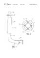
- FIG. 1shows a vertical exhaust having a toroidal absorber attached.
- FIG. 2is a sketch of an idealized representation of the toroidal absorber.
- FIG. 3is a top view of an embodiment of the spring to be used in the toroidal absorber.
- FIG. 4is a front view of the embodiment of the spring shown in FIG. 3 .
- FIG. 5is a cross-sectional view of the embodiment of the spring shown in FIGS. 3 and 4 taken along lines 5 — 5 of FIG. 3 .
- FIG. 6is a front view of the toroidal absorber mounted on a vertical exhaust pipe in which another embodiment of the spring is used.
- FIG. 7is a top view of the toroidal absorber and vertical exhaust pipe seen in FIG. 6 .
- FIG. 8is an amplitude frequency vibration graph of an undampened vertical exhaust system.
- FIG. 9is an amplitude frequency vibration graph of a vertical exhaust system that is dampened by a toroidal absorber.
- FIG. 10is an amplitude frequency vibration graph of a vertical exhaust system that is dampened by a toroidal absorber showing the effect of increasing the mass of the spring-mass system.
- FIG. 11is an amplitude frequency vibration graph of a vertical exhaust system that is dampened by a toroidal absorber illustrating that the effect of increasing the damping between the vibrating system and the absorber is to increase the amplitude of the vibrations in the region of excitation.
- FIG. 1A vertical exhaust stanchion 10 is shown in FIG. 1 .
- the lower end 14 of the vertical exhaust pipe 12is secured to a vehicle support 16 .
- the exhaust gases from the engineare collected in the engine exhaust manifold and exit the manifold into the lower end 14 of the vertical exhaust pipe 12 .
- the exhaust gasesflow upwardly into the muffler 18 where they encounter a labyrinth flow path and finally exit the muffler 18 into the upper end 20 of the vertical exhaust pipe 12 .
- the toroidal absorber 25is shown attached to the upper end 20 of the vertical exhaust pipe 12 above the muffler 18 .
- FIG. 2An idealized representation of a toroidal absorber is shown in FIG. 2 .
- a cast iron toroid 30is suspended by four springs 40 from the vertical exhaust pipe 12 .
- the natural frequency of the toroidal absorbercorresponds to the natural frequency of the vertical exhaust system and thus functions to dampen vibrations in the vertical exhaust system.
- FIGS. 3 through 5show an embodiment of a specific spring 42 for use in this invention.
- FIG. 3is a top view
- FIG. 4is a side view
- FIG. 5is a cross-sectional view taken along lines 5 — 5 of FIG. 3 of spring 42 .
- spring 42is generally sleeve-shaped and includes a shallow rounded groove 44 that encircles the outer bottom edge.
- the toroidal absorber 30is secured to the spring 42 along groove 44 by welding, adhesive or other conventional securing means.
- the cross section of each side of spring 42has an upside down V-shape. There is a flat ring portion 46 along the inner bottom edge.
- the inner surface of the flat ring portion 46is secured to the outer surface of the vertical exhaust pipe 12 by welding, adhesive or other conventional methods.
- the spring section 48having upside down, V-shaped cross-sections extends from the upper edge of the flat ring portion 46 to the rounded groove 44 .
- Spring section 48can flex from a position at which one portion of the shallow rounded groove 44 is contacting the flat ring portion 46 to a second position where another portion of the shallow rounded groove 44 is contacting another portion of the flat ring portion 46 .
- FIG. 6shows a vertical exhaust pipe 12 having toroidal absorber 60 secured thereto.
- the toroidal absorber 60employs a cast iron toroid 62 having a rectangular cross sections. However, the cross sections need not be rectangular. For example, they could be circular, semi-circular or any other closed, curve shape.
- the preferred embodiment of spring 64is utilized for connecting the toroid 62 to the vertical exhaust pipe 12 . As best seen in FIG. 7, the spring 64 of this embodiment is formed from three strips of spring steel 65 - 67 . One end of each strip 65 - 67 is secured to the vertical exhaust pipe 12 and the other end, after wrapping partially around the exhaust pipe 12 , is secured to the internal surface of the toroid 62 .
- FIG. 8is an amplitude-frequency vibration graph for a vertical exhaust system that has not been dampened.
- excitation frequency W fis plotted on the abscissa or X-axis and amplitude A is plotted on the ordinate or Y-axis.
- the two halves of the curveapproach the boundaries of the region of excitation at low amplitude levels. After entering the region of excitation, the two halves of the curve increase in amplitude steeply and approach infinity, which in this situation is resonance.
- the excitation frequencies for this vertical exhaust systemare the frequencies within the region of excitation. Impulses from outside sources having frequencies within this frequency range can damage the vertical exhaust system and force it into resonance.
- the amplitude of the vibration of the vertical exhaust systemgradually increases as the frequency approaches the region of excitation and, once in the region of excitation, increases steeply to the point at which resonance occurred. As this vertical exhaust system approaches resonance, it will be seriously damaged or may even destruct.
- FIG. 9is an amplitude-frequency vibration graph for a vertical exhaust system that is dampened by a toroidal absorber. This graph illustrates the situation where the natural frequency of the vertical exhaust system has been determined and a toroidal absorber has been designed to have a natural frequency equal to that of the vertical exhaust system.
- FIG. 9is the resulting amplitude-frequency graph after such a toroidal absorber was built and mounted on the vertical exhaust system in accordance with this invention.
- the toroidal absorberincludes an element that has a certain mass and a spring or springs that have a certain flexibility that, together, result in a toroidal absorber having a natural frequency that is substantially equal to the natural frequency of the vertical exhaust system.
- the toroidal absorberhas dampened the original natural frequency area of the curve that was within the region of excitation and has, in effect, split the original natural frequency of the exhaust system into two frequencies. Both of the new natural frequencies are, however, outside the range of excitation and the region of excitation is now located between the new pair of natural frequencies of the exhaust system.
- the region of excitationis located between the new pair of natural frequencies of the vertical exhaust system.
- the curve for the vertical exhaust system within the region of excitationhas a low amplitude. As a result of the amplitude being low the life cycle of the vertical exhaust system has been greatly extended.
- the natural frequency for a highway truck vertical exhaust systemcan be theoretically calculated and or determined empirically. The most determinative factor in the specific design being its length, which has little latitude for variation.
- the height of highway trucksis controlled by underpass heights and laws regulating their heights.
- the natural frequency for a highway truck vertical exhaust systemfalls within a small range centered around 11 Hz.
- a toroidal-shaped weight having a natural frequency that corresponds to the natural frequency of the vertical exhaust systemcan be designed in accordance with the following formula:
- the maximum damper mass that can be supported by the muffler tailpipe assemblyshould be determined.
- FIG. 10is an amplitude-frequency vibration graph of a vertical exhaust system that is dampened by a toroidal absorber in accordance with this invention.
- This graphillustrates how by increasing the mass of the toroidal absorber the separation between the pair of natural frequencies of the vertical exhaust system increases.
- the first curve, designated Ahas the lowest mass.
- the third curve, designated Chas the highest mass.
- the curve designated Brepresents an exhaust system having an absorber with a mass between that of curves A and C. It is also shown in this Figure that curve C enters the region of excitation at a lower level than either curve A or B. This is, of course, desirable since the amplitude of the vibrations in the region of excitation is lowest for the C set of curves.
- the mass of the toroidal shaped absorber and the flexibility of the connecting springmust be coordinated to minimize the amplitude of the vibrations in the region of excitation.
- FIG. 11is an amplitude-frequency vibration graph for a number of vertical exhaust systems that are dampened by a toroidal absorber in accordance with this invention.
- the amount of dampinghas been increased as from curve A to curve D.
- This graphillustrates how by increasing the damping between the vertical exhaust system and the toroidal absorber there is a corresponding increase in amplitude of the portion of the curve between the pair of natural frequencies. This increase in amplitude lies within the region of excitation and is thus undesirable.
- the damping between the vibrating system and the absorberis increased for example by utilizing stiffer springs. The ultimate increase in stiffness would be to fix the absorber on the vibrating system, at which point you have returned to an un-dampened system, as is illustrated in FIG. 8, differing only in that an additional mass has been added to the system.
Landscapes
- Engineering & Computer Science (AREA)
- General Engineering & Computer Science (AREA)
- Mechanical Engineering (AREA)
- Chemical & Material Sciences (AREA)
- Combustion & Propulsion (AREA)
- Physics & Mathematics (AREA)
- Acoustics & Sound (AREA)
- Aviation & Aerospace Engineering (AREA)
- Exhaust Silencers (AREA)
- Vibration Prevention Devices (AREA)
Abstract
Description
Claims (5)
Priority Applications (1)
| Application Number | Priority Date | Filing Date | Title |
|---|---|---|---|
| US09/321,476US6412586B1 (en) | 1999-05-27 | 1999-05-27 | Toroidal exhaust vibration absorber |
Applications Claiming Priority (1)
| Application Number | Priority Date | Filing Date | Title |
|---|---|---|---|
| US09/321,476US6412586B1 (en) | 1999-05-27 | 1999-05-27 | Toroidal exhaust vibration absorber |
Publications (1)
| Publication Number | Publication Date |
|---|---|
| US6412586B1true US6412586B1 (en) | 2002-07-02 |
Family
ID=23250747
Family Applications (1)
| Application Number | Title | Priority Date | Filing Date |
|---|---|---|---|
| US09/321,476Expired - Fee RelatedUS6412586B1 (en) | 1999-05-27 | 1999-05-27 | Toroidal exhaust vibration absorber |
Country Status (1)
| Country | Link |
|---|---|
| US (1) | US6412586B1 (en) |
Cited By (15)
| Publication number | Priority date | Publication date | Assignee | Title |
|---|---|---|---|---|
| US20020053765A1 (en)* | 1999-09-27 | 2002-05-09 | Uniroyal Chemical Company Inc | Side bearing pad |
| US6983728B1 (en) | 2004-08-02 | 2006-01-10 | Cnh America Llc | Skid steer loader including muffler support for engine |
| US20070131479A1 (en)* | 2005-12-08 | 2007-06-14 | Mark Brockman | Resonant frequency adjustor and method of utilizing the same |
| US20100252360A1 (en)* | 2005-08-08 | 2010-10-07 | Jacobs John J | Absorptive muffler suspension |
| US20110094489A1 (en)* | 2009-10-27 | 2011-04-28 | Mcpherson Mathew A | String Damper Having Aperture |
| USD661363S1 (en) | 2011-03-03 | 2012-06-05 | Mcp Ip, Llc | Archery bowstring damper |
| US20120247896A1 (en)* | 2011-03-29 | 2012-10-04 | GM Global Technology Operations LLC | Sleeve damper assembly |
| US20130112518A1 (en)* | 2011-11-03 | 2013-05-09 | Samsung Electronics Co., Ltd. | Damper for decreasing a pipevibration |
| US20140234145A1 (en)* | 2011-07-07 | 2014-08-21 | Whirlpool S.A. | Arrangement of components of a linear compressor |
| US20140241911A1 (en)* | 2011-07-19 | 2014-08-28 | Whirlpool S.A. | Leaf spring and compressor with leaf spring |
| US20140301874A1 (en)* | 2011-08-31 | 2014-10-09 | Whirlpool S.A. | Linear compressor based on resonant oscillating mechanism |
| DE102016203329A1 (en)* | 2016-03-01 | 2017-09-07 | Borgwarner Inc. | Vibration-damped adjusting device |
| US11067355B2 (en) | 2014-05-30 | 2021-07-20 | Mcp Ip, Llc | Archery bow cable mounted protector |
| US11629629B2 (en) | 2021-04-08 | 2023-04-18 | International Truck Intellectual Property Company, Llc | Vehicle exhaust pipe support assembly |
| WO2025037169A1 (en)* | 2023-08-14 | 2025-02-20 | Agco International Gmbh | Exhaust stackpipe |
Citations (13)
| Publication number | Priority date | Publication date | Assignee | Title |
|---|---|---|---|---|
| US2856020A (en)* | 1953-12-31 | 1958-10-14 | Gen Motors Corp | Automobile exhaust means |
| US2969416A (en)* | 1959-08-26 | 1961-01-24 | Schwitzer Corp | Cable vibration damper |
| US3142610A (en)* | 1960-04-13 | 1964-07-28 | Wright Barry Corp | Self-damped composite structures |
| US3188644A (en)* | 1961-06-12 | 1965-06-08 | Collins Radio Co | Weighted device for damping out vibration in an antenna element |
| US3246073A (en)* | 1960-10-06 | 1966-04-12 | Bouche | Vibration damper for suspended outdoor wires |
| US3837327A (en)* | 1973-11-19 | 1974-09-24 | Saunders Archery Co | Bowstring silencer for archery bow |
| US3856107A (en)* | 1970-01-21 | 1974-12-24 | Adams R | Tools for use in percussive machines |
| US3911199A (en)* | 1974-04-26 | 1975-10-07 | Westinghouse Electric Corp | Seismic motion-damper for upstanding electrical equipment |
| US4044628A (en)* | 1976-03-24 | 1977-08-30 | U.S. Manufacturing Corporation | Torsional damper |
| US4471853A (en)* | 1983-06-20 | 1984-09-18 | Towmotor Corporation | Mounting arrangement for an exhaust system |
| US4858738A (en)* | 1978-07-26 | 1989-08-22 | Fernando Novoa | System of auxiliary mass dampers to restrain the response of slender elastic structures to vibrations such as from earthquakes |
| US5098226A (en)* | 1990-01-30 | 1992-03-24 | Massachusetts Institute Of Technology | Apparatus and method for damping low frequency perturbations of marine structures |
| US5853018A (en)* | 1997-02-28 | 1998-12-29 | Eaton Corporation | Dampening resonance in a flow regulator |
- 1999
- 1999-05-27USUS09/321,476patent/US6412586B1/ennot_activeExpired - Fee Related
Patent Citations (13)
| Publication number | Priority date | Publication date | Assignee | Title |
|---|---|---|---|---|
| US2856020A (en)* | 1953-12-31 | 1958-10-14 | Gen Motors Corp | Automobile exhaust means |
| US2969416A (en)* | 1959-08-26 | 1961-01-24 | Schwitzer Corp | Cable vibration damper |
| US3142610A (en)* | 1960-04-13 | 1964-07-28 | Wright Barry Corp | Self-damped composite structures |
| US3246073A (en)* | 1960-10-06 | 1966-04-12 | Bouche | Vibration damper for suspended outdoor wires |
| US3188644A (en)* | 1961-06-12 | 1965-06-08 | Collins Radio Co | Weighted device for damping out vibration in an antenna element |
| US3856107A (en)* | 1970-01-21 | 1974-12-24 | Adams R | Tools for use in percussive machines |
| US3837327A (en)* | 1973-11-19 | 1974-09-24 | Saunders Archery Co | Bowstring silencer for archery bow |
| US3911199A (en)* | 1974-04-26 | 1975-10-07 | Westinghouse Electric Corp | Seismic motion-damper for upstanding electrical equipment |
| US4044628A (en)* | 1976-03-24 | 1977-08-30 | U.S. Manufacturing Corporation | Torsional damper |
| US4858738A (en)* | 1978-07-26 | 1989-08-22 | Fernando Novoa | System of auxiliary mass dampers to restrain the response of slender elastic structures to vibrations such as from earthquakes |
| US4471853A (en)* | 1983-06-20 | 1984-09-18 | Towmotor Corporation | Mounting arrangement for an exhaust system |
| US5098226A (en)* | 1990-01-30 | 1992-03-24 | Massachusetts Institute Of Technology | Apparatus and method for damping low frequency perturbations of marine structures |
| US5853018A (en)* | 1997-02-28 | 1998-12-29 | Eaton Corporation | Dampening resonance in a flow regulator |
Cited By (27)
| Publication number | Priority date | Publication date | Assignee | Title |
|---|---|---|---|---|
| US7083165B2 (en)* | 1999-09-27 | 2006-08-01 | Uniroyal Chemical Company, Inc. | Side bearing pad |
| US20020053765A1 (en)* | 1999-09-27 | 2002-05-09 | Uniroyal Chemical Company Inc | Side bearing pad |
| US6983728B1 (en) | 2004-08-02 | 2006-01-10 | Cnh America Llc | Skid steer loader including muffler support for engine |
| US20060021593A1 (en)* | 2004-08-02 | 2006-02-02 | Banks Clayton E Jr | Skid steer loader including muffler support for engine |
| US8141679B2 (en)* | 2005-08-08 | 2012-03-27 | Carrier Corporation | Absorptive muffler suspension |
| US20100252360A1 (en)* | 2005-08-08 | 2010-10-07 | Jacobs John J | Absorptive muffler suspension |
| US20070131479A1 (en)* | 2005-12-08 | 2007-06-14 | Mark Brockman | Resonant frequency adjustor and method of utilizing the same |
| US7753166B2 (en)* | 2005-12-08 | 2010-07-13 | Windsor Machine & Stamping Ltd | Resonant frequency adjustor and method of utilizing the same |
| US8448633B2 (en) | 2009-10-27 | 2013-05-28 | Mcp Ip, Llc | String damper having aperture |
| US9250031B2 (en) | 2009-10-27 | 2016-02-02 | Mcp Ip, Llc | String damper having aperture |
| US9791235B2 (en) | 2009-10-27 | 2017-10-17 | Mcp Ip, Llc | String damper having aperture |
| US20110094489A1 (en)* | 2009-10-27 | 2011-04-28 | Mcpherson Mathew A | String Damper Having Aperture |
| USD661363S1 (en) | 2011-03-03 | 2012-06-05 | Mcp Ip, Llc | Archery bowstring damper |
| US20120247896A1 (en)* | 2011-03-29 | 2012-10-04 | GM Global Technology Operations LLC | Sleeve damper assembly |
| US8701848B2 (en)* | 2011-03-29 | 2014-04-22 | Gm Global Technology Operations | Sleeve damper assembly |
| US20140182988A1 (en)* | 2011-03-29 | 2014-07-03 | GM Global Technology Operations LLC | Sleeve damper assembly |
| US9562526B2 (en)* | 2011-07-07 | 2017-02-07 | Whirlpool S.A. | Arrangement of components of a linear compressor |
| US20140234145A1 (en)* | 2011-07-07 | 2014-08-21 | Whirlpool S.A. | Arrangement of components of a linear compressor |
| US20140241911A1 (en)* | 2011-07-19 | 2014-08-28 | Whirlpool S.A. | Leaf spring and compressor with leaf spring |
| US20140301874A1 (en)* | 2011-08-31 | 2014-10-09 | Whirlpool S.A. | Linear compressor based on resonant oscillating mechanism |
| US9534591B2 (en)* | 2011-08-31 | 2017-01-03 | Whirlpool S.A. | Linear compressor based on resonant oscillating mechanism |
| US8899392B2 (en)* | 2011-11-03 | 2014-12-02 | Samsung Electronics Co., Ltd. | Damper for decreasing a pipe vibration |
| US20130112518A1 (en)* | 2011-11-03 | 2013-05-09 | Samsung Electronics Co., Ltd. | Damper for decreasing a pipevibration |
| US11067355B2 (en) | 2014-05-30 | 2021-07-20 | Mcp Ip, Llc | Archery bow cable mounted protector |
| DE102016203329A1 (en)* | 2016-03-01 | 2017-09-07 | Borgwarner Inc. | Vibration-damped adjusting device |
| US11629629B2 (en) | 2021-04-08 | 2023-04-18 | International Truck Intellectual Property Company, Llc | Vehicle exhaust pipe support assembly |
| WO2025037169A1 (en)* | 2023-08-14 | 2025-02-20 | Agco International Gmbh | Exhaust stackpipe |
Similar Documents
| Publication | Publication Date | Title |
|---|---|---|
| US6412586B1 (en) | Toroidal exhaust vibration absorber | |
| US6854721B2 (en) | Vibration-damping device | |
| US4739962A (en) | Vibration isolator | |
| JP3035334B2 (en) | Spring mounting table | |
| JP6190651B2 (en) | Vibration isolator | |
| US4568067A (en) | Strut suspension for an automotive vehicle | |
| US7275738B2 (en) | Cylindrical fluid-filled vibration damping device | |
| EP0131795A2 (en) | Improved insulator for use in automotive suspension or the like | |
| CN102803783B (en) | Vibrationproof device | |
| US4739978A (en) | Hydraulic antivibration support | |
| US6641119B2 (en) | Vibration-damping device having independent mass member | |
| KR102370154B1 (en) | Engine mount | |
| JPS6011671A (en) | Fuel feeder of internal combustion engine | |
| US6454236B2 (en) | Elastic device for suspending a vibrating structure on a rigid structure | |
| US4467992A (en) | Power-unit mounting structure for automotive vehicle | |
| EP0178652B1 (en) | Liquid-filled type vibration damping structure | |
| US6782981B2 (en) | Antivibration apparatus including a mass damper | |
| US4527009A (en) | Vibration damper with motion limiting feature | |
| JPS62101937A (en) | Improvement of hydraulic type shock-absorbing supporter | |
| FR2571802A1 (en) | TUNABLE VISCOUS ELASTIC SUPPORT FOR MOTOR VEHICLE OR SIMILAR ENGINES | |
| JP5001688B2 (en) | Vibration isolator | |
| SU1184989A1 (en) | Counter-vibration device | |
| JPH0756314B2 (en) | Anti-vibration device | |
| JPH0355777Y2 (en) | ||
| RU199973U1 (en) | VEHICLE POWER UNIT SUSPENSION SUPPORT |
Legal Events
| Date | Code | Title | Description |
|---|---|---|---|
| AS | Assignment | Owner name:NAVISTAR INTERNATIONAL TRANSPORTATION CORP., ILLIN Free format text:ASSIGNMENT OF ASSIGNORS INTEREST;ASSIGNOR:ASKEW, GERALD W.;REEL/FRAME:010118/0938 Effective date:19990521 | |
| AS | Assignment | Owner name:INTERNATIONAL TRUCK AND ENGINE CORPORATION, ILLINO Free format text:CHANGE OF NAME;ASSIGNOR:NAVISTAR INTERNATIONAL TRANSPORTATION CORP.;REEL/FRAME:012520/0708 Effective date:20000223 Owner name:INTERNATIONAL TRUCK INTELLECTUAL PROPERTY COMPANY, Free format text:ASSIGNMENT OF ASSIGNORS INTEREST;ASSIGNOR:INTERNATIONAL TRUCK AND ENGINE CORPORATION;REEL/FRAME:012520/0796 Effective date:20001101 Owner name:INTERNATIONAL TRUCK INTELLECTUAL PROPERTY COMPANY, Free format text:ASSIGNMENT OF ASSIGNORS INTEREST;ASSIGNOR:INTERNATIONAL TRUCK AND ENGINE CORPORATION;REEL/FRAME:012520/0275 Effective date:20001101 | |
| FPAY | Fee payment | Year of fee payment:4 | |
| FPAY | Fee payment | Year of fee payment:8 | |
| AS | Assignment | Owner name:JPMORGAN CHASE BANK, N.A., AS COLLATERAL AGENT, NE Free format text:SECURITY AGREEMENT;ASSIGNORS:INTERNATIONAL ENGINE INTELLECTUAL PROPERTY COMPANY, LLC;INTERNATIONAL TRUCK INTELLECTUAL PROPERTY COMPANY, LLC;NAVISTAR INTERNATIONAL CORPORATION;AND OTHERS;REEL/FRAME:028944/0730 Effective date:20120817 | |
| REMI | Maintenance fee reminder mailed | ||
| LAPS | Lapse for failure to pay maintenance fees | ||
| STCH | Information on status: patent discontinuation | Free format text:PATENT EXPIRED DUE TO NONPAYMENT OF MAINTENANCE FEES UNDER 37 CFR 1.362 | |
| FP | Lapsed due to failure to pay maintenance fee | Effective date:20140702 | |
| AS | Assignment | Owner name:NAVISTAR INTERNATIONAL CORPORATION, ILLINOIS Free format text:RELEASE BY SECURED PARTY;ASSIGNOR:JPMORGAN CHASE BANK, N.A., AS COLLATERAL AGENT;REEL/FRAME:044416/0867 Effective date:20171106 Owner name:INTERNATIONAL ENGINE INTELLECTUAL PROPERTY COMPANY Free format text:RELEASE BY SECURED PARTY;ASSIGNOR:JPMORGAN CHASE BANK, N.A., AS COLLATERAL AGENT;REEL/FRAME:044416/0867 Effective date:20171106 Owner name:INTERNATIONAL TRUCK INTELLECTUAL PROPERTY COMPANY, Free format text:RELEASE BY SECURED PARTY;ASSIGNOR:JPMORGAN CHASE BANK, N.A., AS COLLATERAL AGENT;REEL/FRAME:044416/0867 Effective date:20171106 Owner name:NAVISTAR, INC., ILLINOIS Free format text:RELEASE BY SECURED PARTY;ASSIGNOR:JPMORGAN CHASE BANK, N.A., AS COLLATERAL AGENT;REEL/FRAME:044416/0867 Effective date:20171106 |