US6412293B1 - Scroll machine with continuous capacity modulation - Google Patents
Scroll machine with continuous capacity modulationDownload PDFInfo
- Publication number
- US6412293B1 US6412293B1US09/686,561US68656100AUS6412293B1US 6412293 B1US6412293 B1US 6412293B1US 68656100 AUS68656100 AUS 68656100AUS 6412293 B1US6412293 B1US 6412293B1
- Authority
- US
- United States
- Prior art keywords
- air conditioning
- conditioning system
- compressor
- accordance
- capacity
- Prior art date
- Legal status (The legal status is an assumption and is not a legal conclusion. Google has not performed a legal analysis and makes no representation as to the accuracy of the status listed.)
- Expired - Lifetime, expires
Links
- 239000012530fluidSubstances0.000claimsabstractdescription65
- 238000004378air conditioningMethods0.000claimsdescription77
- 238000004891communicationMethods0.000claimsdescription32
- 239000003507refrigerantSubstances0.000claimsdescription28
- 230000001351cycling effectEffects0.000claimsdescription19
- 230000004044responseEffects0.000claimsdescription11
- 238000004804windingMethods0.000claimsdescription5
- 239000012080ambient airSubstances0.000claimsdescription3
- 230000008901benefitEffects0.000abstractdescription4
- 238000003466weldingMethods0.000abstractdescription2
- 238000010276constructionMethods0.000abstract1
- 230000007257malfunctionEffects0.000abstract1
- 238000005057refrigerationMethods0.000description8
- 238000007789sealingMethods0.000description6
- 239000007788liquidSubstances0.000description5
- 230000003111delayed effectEffects0.000description4
- 238000000034methodMethods0.000description4
- 238000002347injectionMethods0.000description3
- 239000007924injectionSubstances0.000description3
- 230000009467reductionEffects0.000description3
- 230000003044adaptive effectEffects0.000description2
- 230000002411adverseEffects0.000description2
- 230000008859changeEffects0.000description2
- 238000013461designMethods0.000description2
- 230000007246mechanismEffects0.000description2
- 238000012360testing methodMethods0.000description2
- 238000013022ventingMethods0.000description2
- 230000009471actionEffects0.000description1
- 239000003570airSubstances0.000description1
- 229910052782aluminiumInorganic materials0.000description1
- XAGFODPZIPBFFR-UHFFFAOYSA-NaluminiumChemical compound[Al]XAGFODPZIPBFFR-UHFFFAOYSA-N0.000description1
- 230000003466anti-cipated effectEffects0.000description1
- 238000013459approachMethods0.000description1
- 230000000712assemblyEffects0.000description1
- 238000000429assemblyMethods0.000description1
- 230000015556catabolic processEffects0.000description1
- 230000006835compressionEffects0.000description1
- 238000007906compressionMethods0.000description1
- 238000006731degradation reactionMethods0.000description1
- 230000003292diminished effectEffects0.000description1
- 230000000694effectsEffects0.000description1
- 238000007726management methodMethods0.000description1
- 229910052751metalInorganic materials0.000description1
- 239000002184metalSubstances0.000description1
- 239000000203mixtureSubstances0.000description1
- 230000004048modificationEffects0.000description1
- 238000012986modificationMethods0.000description1
- 230000002093peripheral effectEffects0.000description1
- 230000008569processEffects0.000description1
- 238000004513sizingMethods0.000description1
- 239000000243solutionSubstances0.000description1
- 230000001360synchronised effectEffects0.000description1
Images


Classifications
- F—MECHANICAL ENGINEERING; LIGHTING; HEATING; WEAPONS; BLASTING
- F04—POSITIVE - DISPLACEMENT MACHINES FOR LIQUIDS; PUMPS FOR LIQUIDS OR ELASTIC FLUIDS
- F04C—ROTARY-PISTON, OR OSCILLATING-PISTON, POSITIVE-DISPLACEMENT MACHINES FOR LIQUIDS; ROTARY-PISTON, OR OSCILLATING-PISTON, POSITIVE-DISPLACEMENT PUMPS
- F04C18/00—Rotary-piston pumps specially adapted for elastic fluids
- F04C18/02—Rotary-piston pumps specially adapted for elastic fluids of arcuate-engagement type, i.e. with circular translatory movement of co-operating members, each member having the same number of teeth or tooth-equivalents
- F—MECHANICAL ENGINEERING; LIGHTING; HEATING; WEAPONS; BLASTING
- F25—REFRIGERATION OR COOLING; COMBINED HEATING AND REFRIGERATION SYSTEMS; HEAT PUMP SYSTEMS; MANUFACTURE OR STORAGE OF ICE; LIQUEFACTION SOLIDIFICATION OF GASES
- F25B—REFRIGERATION MACHINES, PLANTS OR SYSTEMS; COMBINED HEATING AND REFRIGERATION SYSTEMS; HEAT PUMP SYSTEMS
- F25B49/00—Arrangement or mounting of control or safety devices
- F25B49/02—Arrangement or mounting of control or safety devices for compression type machines, plants or systems
- F25B49/022—Compressor control arrangements
- F—MECHANICAL ENGINEERING; LIGHTING; HEATING; WEAPONS; BLASTING
- F04—POSITIVE - DISPLACEMENT MACHINES FOR LIQUIDS; PUMPS FOR LIQUIDS OR ELASTIC FLUIDS
- F04C—ROTARY-PISTON, OR OSCILLATING-PISTON, POSITIVE-DISPLACEMENT MACHINES FOR LIQUIDS; ROTARY-PISTON, OR OSCILLATING-PISTON, POSITIVE-DISPLACEMENT PUMPS
- F04C18/00—Rotary-piston pumps specially adapted for elastic fluids
- F04C18/02—Rotary-piston pumps specially adapted for elastic fluids of arcuate-engagement type, i.e. with circular translatory movement of co-operating members, each member having the same number of teeth or tooth-equivalents
- F04C18/0207—Rotary-piston pumps specially adapted for elastic fluids of arcuate-engagement type, i.e. with circular translatory movement of co-operating members, each member having the same number of teeth or tooth-equivalents both members having co-operating elements in spiral form
- F04C18/0215—Rotary-piston pumps specially adapted for elastic fluids of arcuate-engagement type, i.e. with circular translatory movement of co-operating members, each member having the same number of teeth or tooth-equivalents both members having co-operating elements in spiral form where only one member is moving
- F—MECHANICAL ENGINEERING; LIGHTING; HEATING; WEAPONS; BLASTING
- F04—POSITIVE - DISPLACEMENT MACHINES FOR LIQUIDS; PUMPS FOR LIQUIDS OR ELASTIC FLUIDS
- F04C—ROTARY-PISTON, OR OSCILLATING-PISTON, POSITIVE-DISPLACEMENT MACHINES FOR LIQUIDS; ROTARY-PISTON, OR OSCILLATING-PISTON, POSITIVE-DISPLACEMENT PUMPS
- F04C28/00—Control of, monitoring of, or safety arrangements for, pumps or pumping installations specially adapted for elastic fluids
- F04C28/10—Control of, monitoring of, or safety arrangements for, pumps or pumping installations specially adapted for elastic fluids characterised by changing the positions of the inlet or outlet openings with respect to the working chamber
- F04C28/14—Control of, monitoring of, or safety arrangements for, pumps or pumping installations specially adapted for elastic fluids characterised by changing the positions of the inlet or outlet openings with respect to the working chamber using rotating valves
- F—MECHANICAL ENGINEERING; LIGHTING; HEATING; WEAPONS; BLASTING
- F25—REFRIGERATION OR COOLING; COMBINED HEATING AND REFRIGERATION SYSTEMS; HEAT PUMP SYSTEMS; MANUFACTURE OR STORAGE OF ICE; LIQUEFACTION SOLIDIFICATION OF GASES
- F25B—REFRIGERATION MACHINES, PLANTS OR SYSTEMS; COMBINED HEATING AND REFRIGERATION SYSTEMS; HEAT PUMP SYSTEMS
- F25B1/00—Compression machines, plants or systems with non-reversible cycle
- F25B1/04—Compression machines, plants or systems with non-reversible cycle with compressor of rotary type
- F25B1/047—Compression machines, plants or systems with non-reversible cycle with compressor of rotary type of screw type
- F—MECHANICAL ENGINEERING; LIGHTING; HEATING; WEAPONS; BLASTING
- F04—POSITIVE - DISPLACEMENT MACHINES FOR LIQUIDS; PUMPS FOR LIQUIDS OR ELASTIC FLUIDS
- F04C—ROTARY-PISTON, OR OSCILLATING-PISTON, POSITIVE-DISPLACEMENT MACHINES FOR LIQUIDS; ROTARY-PISTON, OR OSCILLATING-PISTON, POSITIVE-DISPLACEMENT PUMPS
- F04C14/00—Control of, monitoring of, or safety arrangements for, machines, pumps or pumping installations
- F04C14/18—Control of, monitoring of, or safety arrangements for, machines, pumps or pumping installations characterised by varying the volume of the working chamber
- F—MECHANICAL ENGINEERING; LIGHTING; HEATING; WEAPONS; BLASTING
- F04—POSITIVE - DISPLACEMENT MACHINES FOR LIQUIDS; PUMPS FOR LIQUIDS OR ELASTIC FLUIDS
- F04C—ROTARY-PISTON, OR OSCILLATING-PISTON, POSITIVE-DISPLACEMENT MACHINES FOR LIQUIDS; ROTARY-PISTON, OR OSCILLATING-PISTON, POSITIVE-DISPLACEMENT PUMPS
- F04C2270/00—Control; Monitoring or safety arrangements
- F04C2270/01—Load
- F—MECHANICAL ENGINEERING; LIGHTING; HEATING; WEAPONS; BLASTING
- F04—POSITIVE - DISPLACEMENT MACHINES FOR LIQUIDS; PUMPS FOR LIQUIDS OR ELASTIC FLUIDS
- F04C—ROTARY-PISTON, OR OSCILLATING-PISTON, POSITIVE-DISPLACEMENT MACHINES FOR LIQUIDS; ROTARY-PISTON, OR OSCILLATING-PISTON, POSITIVE-DISPLACEMENT PUMPS
- F04C2270/00—Control; Monitoring or safety arrangements
- F04C2270/18—Pressure
- F—MECHANICAL ENGINEERING; LIGHTING; HEATING; WEAPONS; BLASTING
- F04—POSITIVE - DISPLACEMENT MACHINES FOR LIQUIDS; PUMPS FOR LIQUIDS OR ELASTIC FLUIDS
- F04C—ROTARY-PISTON, OR OSCILLATING-PISTON, POSITIVE-DISPLACEMENT MACHINES FOR LIQUIDS; ROTARY-PISTON, OR OSCILLATING-PISTON, POSITIVE-DISPLACEMENT PUMPS
- F04C2270/00—Control; Monitoring or safety arrangements
- F04C2270/19—Temperature
- F—MECHANICAL ENGINEERING; LIGHTING; HEATING; WEAPONS; BLASTING
- F04—POSITIVE - DISPLACEMENT MACHINES FOR LIQUIDS; PUMPS FOR LIQUIDS OR ELASTIC FLUIDS
- F04C—ROTARY-PISTON, OR OSCILLATING-PISTON, POSITIVE-DISPLACEMENT MACHINES FOR LIQUIDS; ROTARY-PISTON, OR OSCILLATING-PISTON, POSITIVE-DISPLACEMENT PUMPS
- F04C2270/00—Control; Monitoring or safety arrangements
- F04C2270/58—Valve parameters
- F—MECHANICAL ENGINEERING; LIGHTING; HEATING; WEAPONS; BLASTING
- F04—POSITIVE - DISPLACEMENT MACHINES FOR LIQUIDS; PUMPS FOR LIQUIDS OR ELASTIC FLUIDS
- F04C—ROTARY-PISTON, OR OSCILLATING-PISTON, POSITIVE-DISPLACEMENT MACHINES FOR LIQUIDS; ROTARY-PISTON, OR OSCILLATING-PISTON, POSITIVE-DISPLACEMENT PUMPS
- F04C2270/00—Control; Monitoring or safety arrangements
- F04C2270/90—Remote control, e.g. wireless, via LAN, by radio, or by a wired connection from a central computer
- F—MECHANICAL ENGINEERING; LIGHTING; HEATING; WEAPONS; BLASTING
- F04—POSITIVE - DISPLACEMENT MACHINES FOR LIQUIDS; PUMPS FOR LIQUIDS OR ELASTIC FLUIDS
- F04C—ROTARY-PISTON, OR OSCILLATING-PISTON, POSITIVE-DISPLACEMENT MACHINES FOR LIQUIDS; ROTARY-PISTON, OR OSCILLATING-PISTON, POSITIVE-DISPLACEMENT PUMPS
- F04C23/00—Combinations of two or more pumps, each being of rotary-piston or oscillating-piston type, specially adapted for elastic fluids; Pumping installations specially adapted for elastic fluids; Multi-stage pumps specially adapted for elastic fluids
- F04C23/008—Hermetic pumps
- F—MECHANICAL ENGINEERING; LIGHTING; HEATING; WEAPONS; BLASTING
- F25—REFRIGERATION OR COOLING; COMBINED HEATING AND REFRIGERATION SYSTEMS; HEAT PUMP SYSTEMS; MANUFACTURE OR STORAGE OF ICE; LIQUEFACTION SOLIDIFICATION OF GASES
- F25B—REFRIGERATION MACHINES, PLANTS OR SYSTEMS; COMBINED HEATING AND REFRIGERATION SYSTEMS; HEAT PUMP SYSTEMS
- F25B2600/00—Control issues
- F25B2600/02—Compressor control
- F25B2600/026—Compressor control by controlling unloaders
- F25B2600/0262—Compressor control by controlling unloaders internal to the compressor
- F—MECHANICAL ENGINEERING; LIGHTING; HEATING; WEAPONS; BLASTING
- F25—REFRIGERATION OR COOLING; COMBINED HEATING AND REFRIGERATION SYSTEMS; HEAT PUMP SYSTEMS; MANUFACTURE OR STORAGE OF ICE; LIQUEFACTION SOLIDIFICATION OF GASES
- F25B—REFRIGERATION MACHINES, PLANTS OR SYSTEMS; COMBINED HEATING AND REFRIGERATION SYSTEMS; HEAT PUMP SYSTEMS
- F25B2700/00—Sensing or detecting of parameters; Sensors therefor
- F25B2700/05—Load shedding of a compressor
Definitions
- the present inventionrelates generally to scroll compressors and more specifically to continuous capacity modulation systems of the delayed suction type for such compressors.
- Utility summer peak demand limit controlhas historically been the driving demand behind the need for load shedding for refrigeration compressors.
- the traditional method used for load sheddinghas been to have the room thermostat perform an on/off duty cycle of the air conditioning system on the order of every 15 minutes.
- the disadvantages to this methodare that the control and communication hardware cost to implement this system is higher than the savings from demand-side management, and the comfort provided by the system is diminished with long off cycles.
- Another approach that utilities are usingis variable speed air conditioning systems that can modulate capacity and power continuously down to about 75%-80% of capacity.
- variable speed invertersare expensive, they also reduce power supply quality through harmonics, thus defeating the utilities original interest.
- a two-step compressor using a two-speed or a reversing motoris another option, but these systems have limited capability because the motor has to be shut down for 1-2 minutes between speed changes to assure reliability.
- One possibility to accomplish this load sheddingis to utilize a capacity modulated compressor.
- a wide variety of systemshave been developed in order to accomplish capacity modulation for refrigerant compressors, most of which delay the initial sealing point of the moving fluid pockets defined by the scroll members.
- such systemscommonly employ a pair of vent passages communicating between suction pressure and the outermost pair of moving fluid pockets. Typically these passages open into the moving fluid pockets at a position within 360° of the sealing point of the outer ends of the wraps.
- Some systemsemploy a separate valve member for each of these vent passages. The valve members are intended to be operated simultaneously so as to ensure a pressure balance between the two fluid pockets.
- Other systemsemploy additional passages to place the two vent passages in fluid communication, thereby enabling use of a single valve to control capacity modulation.
- a capacity modulation system for scroll compressors of the delayed suction typehas been developed in which a valving ring is movably supported on the non-orbiting scroll member.
- An actuating pistonis provided which operates to rotate the valving ring relative to the non-orbiting scroll member to thereby selectively open and close one or more vent passages which communicate with selective ones of the moving fluid pockets to thereby vent the pockets to suction.
- a scroll-type compressor incorporating this type of capacity modulation systemis disclosed in U.S. Pat. Nos. 5,678,985 and 6,123,517, the disclosures of which are incorporated by reference. In these capacity modulation systems, the actuating piston is operated by fluid pressure controlled by a solenoid valve.
- the solenoid valve and fluid pressure supply and vent linesare positioned externally of the compressor shell.
- the solenoid valveis positioned externally of the compressor shell, but the fluid pressure supply and vent lines are positioned internally of the compressor shell.
- the object of this inventionis to solve the dilemma between demand limit control and the comfort and reliability of the system.
- the above-discussed capacity modulated systemsprovide a two-step scroll compressor that can be unloaded to operate at approximately 65% of capacity using a solenoid mechanism.
- This solenoid mechanismcan be activated by the room thermostat directly or it can be activated by a system control module.
- the low-capacity statewhile being referred to as approximately 65%, can actually be designed to be a different percentage if desired.
- the solenoidis capable of being “switched on the fly” reliably, thus offering continuous capacity control between the low-capacity (i.e., 65%) and full capacity (100%) by pulse width modulation control thereby providing a good balance between peak demand reduction and comfort.
- the control solution of the present inventionconsists of a two-step compressor with its integral unloading solenoid and a Pulse Width Modulated (PWM) control module with software logic which controls the duty-cycle of the solenoid based on an external utility communication signal, a thermostat signal and the outdoor ambient temperature.
- the duty-cyclecan also be controlled based on a load sensor, which can be either a temperature, a pressure, a voltage sensor or a current sensor located within the A/C system which provides an indication of the max-load operating condition of the compressor.
- the compressor motorremains energized continuously during the duty cycling of the solenoid. Additionally, the evaporator and condenser fan speeds can also be reduced accordingly in proportion to the compressor duty cycle to maximize comfort and system sufficiency.
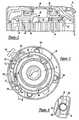
- FIG. 1is a fragmentary section view of a scroll-type compressor incorporating the continuous capacity modulation system of the present invention
- FIG. 2is a fragmentary view of the compressor of FIG. 1 showing the valving ring in a closed or unmodulated position;
- FIG. 3is a plan view of the compressor shown in FIG. 1 with the top portion of the outer shell removed;
- FIG. 4is an enlarged view showing a portion of a modified valving ring
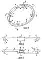
- FIG. 5is a perspective view of the valving ring incorporated in the compressor of FIG. 1;
- FIGS. 6 and 7are section views of the valving ring of FIG. 4, the sections being taken along lines 6 — 6 and 7 — 7 respectively;
- FIG. 8is a fragmentary section view showing the scroll assembly forming a part of the compressor of FIG. 1, the section being taken along line 8 — 8 thereof;
- FIG. 9is an enlarged detailed view of the actuating assembly incorporated in the compressor of FIG. 1;
- FIG. 10is a perspective view of the compressor of FIG. 1 with portions of the outer shell broken away;
- FIG. 11is a fragmentary section view of the compressor of FIG. 1 showing the pressurized fluid supply passages provided in the non-orbiting scroll;
- FIG. 12is an enlarged section view of the solenoid valve assembly incorporated in the compressor of FIG. 1;
- FIG. 13is a view similar to that of FIG. 12 but showing a modified solenoid valve assembly
- FIG. 14is a view similar to that of FIG. 9 but showing a modified actuating assembly adapted for use with the solenoid valve assembly of FIG. 13;
- FIG. 15is a view similar to that of FIGS. 12 and 13 but showing another embodiment of the solenoid valve assembly, all in accordance with the present invention.
- FIG. 16is a schematic view showing the control architecture for the continuous capacity control system of the present invention.
- FIG. 1a hermatic refrigeration compressor of the scroll type indicated generally at 10 incorporating a continuous capacity modulation system in accordance with the present invention.
- Compressor 10is generally of the type disclosed in U.S. Pat. No. 4,767,293 issued Aug. 30, 1988 and assigned to the same assignee as the present application the disclosure of which is hereby incorporated by reference.
- Compressor 10includes a hermetically sealed outer shell 12 within which is disposed orbiting and non-orbiting scroll members 14 and 16 each of which include upstanding interleaved spiral wraps 18 and 20 which define moving fluid pockets 22 , 24 which progressively decrease in size as they move inwardly from the outer periphery of the scroll members 14 and 16 .
- a main bearing housing 26is provided which is supported by outer shell 12 and which in turn movably supports orbiting scroll member 14 for relative orbital movement with respect to non-orbiting scroll member 16 .
- Non-orbiting scroll member 16is supported by and secured to main bearing housing 26 for limited axial movement with respect thereto in a suitable manner such as disclosed in U.S. Pat. No. 5,407,335 issued Apr. 18, 1995 and assigned to the same assignee as the present application, the disclosure of which is hereby incorporated by reference.
- a drive shaft 28is rotatably supported by main bearing housing 26 and includes an eccentric pin 30 at the upper end thereof drivingly connected to orbiting scroll member 14 .
- a motor rotor 32is secured to the lower end of drive shaft 28 and cooperates with a stator 34 supported by outer shell 12 to rotatably drive shaft 28 .
- Outer shell 12includes a muffler plate 36 which divides the interior thereof into a first lower chamber 38 at substantially suction pressure and an upper chamber 40 at discharge pressure.
- a suction inlet 42is provided opening into lower chamber 38 for supplying refrigerant for compression and a discharge outlet 44 is provided from discharge chamber 40 to direct compressed refrigerant to the refrigeration system.
- scroll compressor 12is typical of such scroll-type refrigeration compressors.
- suction gas directed to lower chamber 38 via suction inlet 42is drawn into the moving fluid pockets 22 and 24 as orbiting scroll member 14 orbits with respect to non-orbiting scroll member 16 .
- this suction gasis compressed and subsequently discharged into discharge chamber 40 via a center discharge passage 46 in non-orbiting scroll member 16 and discharge opening 48 in muffler plate 36 .
- Compressed refrigerantis then supplied to the refrigeration system via discharge outlet 44 .
- compressor 10is provided with a continuous capacity modulation system.
- the continuous capacity modulation systemallows the compressor to meet the limit controls and load shedding that have been demanded by the utility summer peak requirements.
- the continuous capacity modulation systemincludes an annular valving ring 50 movably mounted on non-orbiting scroll member 16 , an actuating assembly 52 supported within shell 12 and a control system 54 for controlling operation of the actuating assembly.
- valving ring 50comprises a generally circularly shaped main body portion 56 having a pair of substantially diametrically opposed radially inwardly extending protrusions 58 and 60 provided thereon of substantially identical predetermined axial and circumferential dimensions. Suitable substantially identical circumferentially extending guide surfaces 62 , 64 and 66 , 68 are provided adjacent axially opposite sides of protrusions 58 and 60 , respectively.
- two pairs of substantially identical circumferentially extending axially spaced guide surfaces 70 , 72 and 74 , 76are provided on main body 56 being positioned in substantially diametrically opposed relationship to each other and spaced circumferentially approximately 90° from respective protrusions 58 and 60 .
- guide surfaces 72 and 74project radially inwardly slightly from main body 56 as do guide surfaces 62 and 66 .
- guide surfaces 72 , 74 and 62 , 66are all axially aligned and lie along the periphery of a circle of a radius slightly less than the radius of main body 56 .
- guide surfaces 70 and 76project radially inwardly slightly from main body 56 as do guide surfaces 64 and 68 with which they are preferably axially aligned. Also surfaces 70 , 76 and 64 , 68 lie along the periphery of a circle of a radius slightly less than the radius of main body 56 and preferably substantially equal to the radius of the circle along which surfaces 72 , 74 and 62 , 66 lie.
- Main body 56also includes a circumferentially extending stepped portion 78 which includes an axially extending circumferentially facing stop surface 79 at one end. Step portion 78 is positioned between protrusion 60 and guide surfaces 70 , 72 .
- a pin member 80is also provided extending axially upwardly adjacent one end of stepped portion 78 .
- Valving ring 50may be fabricated from a suitable metal such as aluminum or alternatively may be formed from a suitable polymeric composition and pin 80 may be either pressed into a suitable opening provided therein or integrally formed therewith.
- valving ring 50is designed to be movably mounted on non-orbiting scroll member 16 .
- non-orbiting scroll member 16includes a radially outwardly facing cylindrical sidewall portion 82 thereon having an annular groove 84 formed therein adjacent the upper end thereof.
- a pair of diametrically opposed substantially identical radially inwardly extending notches 86 and 88are provided in non-orbiting scroll member 16 each opening into groove 84 as best seen with reference to FIG. 3 .
- Notches 86 and 88have a circumferentially extending dimension slightly larger than the circumferential extent of protrusions 58 and 60 on valving ring 50 .
- Groove 84is sized to movably accommodate protrusions 58 and 60 when valving ring is assembled thereto and notches 86 and 88 are sized to enable protrusions 58 and 60 to be moved into groove 84 . Additionally, cylindrical portion 82 will have a diameter such that guide surfaces 62 , 64 , 66 , 68 , 70 , 72 , 74 and 76 will slidingly support rotary movement of valving ring 50 with respect to non-orbiting scroll member 16 .
- Non-orbiting scroll member 16also includes a pair of generally diametrically opposed radially extending passages 90 and 92 opening into the inner surface of groove 84 and extending generally radially inwardly through the end plate of non-orbiting scroll member 16 .
- An axially extending passage 94places the inner end of passage 90 in fluid communication with moving fluid pocket 22 while a second axially extending passage 96 places the inner end of passage 92 in fluid communication with moving fluid pocket 24 .
- passages 94 and 96will be oval in shape so as to maximize the size of the opening thereof without having a width greater than the width of the wrap of the orbiting scroll member 14 .
- Passage 94is positioned adjacent an inner sidewall surface of scroll wrap 20 and passage 96 is positioned adjacent an outer sidewall surface of wrap 20 .
- passages 94 and 96may be round if desired however the diameter thereof should be such that the opening does not extend to the radially inner side of the orbiting scroll member 14 as it passes thereover.
- actuating assembly 52includes a piston and cylinder assembly 98 and a return spring assembly 99 .
- Piston and cylinder assembly 98includes a housing 100 having a bore defining a cylinder 104 extending inwardly from one end thereof and within which a piston 106 is movably disposed.
- An outer end 107 of piston 106projects axially outwardly from one end of housing 100 and includes an elongated or oval-shaped opening 108 therein adapted to receive pin 80 forming a part of valving ring 50 .
- Elongated or oval opening 108is designed to accommodate the arcuate movement of pin 80 relative to the linear movement of piston end 107 during operation.
- a depending portion 110 of housing 100has secured thereto a suitably sized mounting flange 112 which is adapted to enable housing 100 to be secured to a suitable flange member 114 by bolts 116 .
- Flange 114is in turn suitably supported within outer shell 12 such as by bearing housing 26 .
- a passage 118is provided in depending portion 110 extending upwardly from the lower end thereof and opening into a laterally extending passage 120 which in turn opens into the inner end of cylinder 104 .
- a second laterally extending passage 124 provided in depending portion 110opens outwardly through the sidewall thereof and communicates at its inner end with passage 118 .
- a second relatively small laterally extending passage 128extends from fluid passage 118 in the opposite direction of fluid passage 120 and opens outwardly through an end wall 130 of housing 100 .
- a pin member 132is provided upstanding from housing 100 to which is connected one end of a return spring 134 the other end of which is connected to an extended portion of pin 80 .
- Return spring 134will be of such a length and strength as to urge ring 50 and piston 106 into the position shown in FIG. 9 when cylinder 104 is fully vented via passage 128 .
- control system 54includes a valve body 136 having a radially outwardly extending flange 137 including a conical surface 138 on one side thereof.
- Valve body 136is inserted into an opening 140 in outer shell 12 and positioned with conical surface 138 abutting the peripheral edge of opening 140 and then welded to shell 12 with cylindrical portion 300 projecting outwardly therefrom.
- Cylindrical portion 300 of valve bodyincludes an enlarged diameter threaded bore 302 extending axially inwardly and opening into a recessed area 154 .
- Valve body 136includes a housing 142 having a first passage 144 extending downwardly from a substantially flat upper surface 146 and intersecting a second laterally extending passage 148 which opens outwardly into the area of opening 140 in shell 12 .
- a third passage 150also extends downwardly from surface 146 and intersects a fourth laterally extending passage 152 which also opens outwardly into a recessed area 154 provided in the end portion of body 136 .
- a manifold 156is sealingly secured to surface 146 by means of suitable fasteners and includes fittings for connection of one end of each of fluid lines 160 and 162 so as to place them in sealed fluid communication with respective passages 150 and 144 .
- a solenoid coil assembly 164is designed to be sealingly secured to valve body 136 and includes an elongated tubular member 304 having a threaded fitting 306 sealingly secured to the open end thereof. Threaded fitting 306 is adapted to be threadedly received within bore 302 and sealed thereto by means of 0 -ring 308 .
- a plunger 168is movably disposed within tubular member 304 and is biased outwardly therefrom by spring 174 which bears against closed end 308 of tubular member 304 .
- a valve member 176is provided on the outer end of plunger 168 and cooperates with valve seat 178 to selectively close off passage 148 .
- a solenoid coil 172is positioned on tubular member 304 and secured thereto by means of nut 310 threaded on the outer end of tubular member 304 .
- an axially extending passage 179extends downwardly from discharge port 46 and connects to a generally radially extending passage 180 in non-orbiting scroll member 16 .
- Passage 180extends radially and opens outwardly through the circumferential sidewall of non-orbiting scroll 16 as best seen with reference to FIG. 11 .
- the other end of fluid line 160is sealingly connected to passage 180 whereby a supply of compressed fluid may be supplied from discharge port 46 to valve body 136 .
- a circumferentially elongated opening 182is provided In valving ring 50 suitably positioned so as to enable fluid line 160 to pass therethrough while accommodating the rotational movement of ring 50 with respect to non-orbiting scroll member 16 .
- fluid line 162extends from valve body 136 and is connected to passage 124 provided in depending portion 110 of housing 100 .
- Valving ring 50may be easily assembled to non-orbiting scroll member 16 by merely aligning protrusions 58 and 60 with respective notches 86 and 88 and moving protrusions 58 and 60 into annular groove 84 . Thereafter valving ring 50 is rotated into the desired position with the axially upper and lower surfaces of protrusions 58 and 60 cooperating with guide surfaces 62 , 64 , 66 , 68 , 70 , 72 , 74 and 76 to movably support valving ring 50 on non-orbiting scroll member 50 . Thereafter, housing 100 of actuating assembly 52 may be positioned on mounting flange 114 with piston end 107 receiving pin 80 . One end of spring 134 may then be connected to pin 132 . Thereafter, the other end of spring 134 may be connected to pin 80 thus completing the assembly process.
- non-orbiting scroll member 16is typically secured to main bearing housing 26 by suitable bolts 184 prior to assembly of valving ring 50 , it may in some cases be preferable to assemble this continuous capacity modulation component to non-orbiting scroll member 16 prior to assembly of non-orbiting scroll member 16 to main bearing housing 26 . This may be easily accomplished by merely providing a plurality of suitably positioned arcuate cutouts 186 along the periphery of valving ring 50 as shown in FIG. 4 . These cutouts will afford access to securing bolts 184 with valving ring assembled to non-orbiting scroll member 16 .
- an indoor unit control module 190will operate in response to a signal from sensors 188 to energize solenoid coil 172 of solenoid assembly 164 thereby causing plunger 168 to be moved out of engagement with valve seat 178 thereby placing passages 148 and 152 in fluid communication. Pressurized fluid at substantially discharge pressure will then be allowed to flow from discharge port 46 to cylinder 104 via passages 179 , 180 , fluid line 160 , passages 150 , 152 , 148 , 144 , fluid line 162 and passages 124 , 118 and 120 .
- sensors 188When the load conditions change to the point that the full capacity of compressor 10 is not required, sensors 188 will provide a signal indicative thereof to controller 190 which in turn will deenergize coil 172 of solenoid assembly 164 . Plunger 168 will then move outwardly from tubular member 304 under the biasing action of spring 174 thereby moving valve 176 into sealing engagement with seat 178 thus closing off passage 148 and the flow of pressurized fluid therethrough. It is noted that recess 154 will be in continuous fluid communication with discharge port 46 and hence continuously subject to discharge pressure. This discharge pressure will aid in biasing valve 176 into fluid tight sealing engagement with valve seat 178 as well as retaining same in such relationship.
- the pressurized gas contained in cylinder 104will bleed back into chamber 38 via vent passage 128 thereby enabling spring 134 to rotate valving ring 50 back to a position in which passages 90 and 92 are no longer closed off by protrusions 58 and 60 .
- Spring 134will also move piston 106 inwardly with respect to cylinder 104 . In this position a portion of the suction gas being drawn into the moving fluid pockets defined by the interengaging scroll members 14 and 16 will be exhausted or vented through passages 90 and 92 until such time as the moving fluid pockets have moved out of communication with ports 94 and 96 thus reducing the volume of the suction gas being compressed and hence the capacity of the compressor.
- the speed with which the valving ring may be moved between the modulated position of FIG. 1 and the unmodulated position of FIG. 2will be directly related to the relative size of vent passage 128 and the supply lines.
- passage 128is continuously open to chamber 38 which is at suction pressure
- coil 172 of solenoid assembly 164when coil 172 of solenoid assembly 164 is energized a portion of the pressurized fluid flowing from discharge port 46 will be continuously vented to suction pressure.
- the volume of this fluidwill be controlled by the relative sizing of passage 128 .
- passage 128is reduced in size, the time required to vent cylinder 104 will increase thus increasing the time required to switch from reduced capacity to full capacity.
- FIGS. 13 and 14show a modified valve body 136 ′ incorporating a vent passage 192 which will operate to continuously vent passage 144 ′ to suction pressure and hence allow cylinder 104 to vent to suction via line 162 .
- FIG. 14in turn shows a modified piston and cylinder assembly 98 ′ in which vent passage 128 has been deleted.
- the operation and function of valve body 136 ′ and piston cylinder assembly 98 ′will otherwise be substantially identical to that disclosed above. Accordingly, corresponding portions of valve bodies 136 and 136 ′ piston and cylinder assemblies 98 and 98 ′ are substantially identical and have each been indicated by the same reference numbers primed.
- valve body 194is secured to shell 12 in the same manner as described above and includes an elongated central bore 196 within which is movably disposed a spool valve 198 .
- Spool valve 198extends outwardly through shell 12 into solenoid coil 200 and is adapted to be moved longitudinally outwardly from valve body 194 upon energization of solenoid coil 200 .
- a coil spring 202operates to bias spool valve 198 into valve body 194 when coil 200 is not energized.
- Spool valve 198includes an elongated axially extending central passage 204 the inner end of which is plugged via plug 206 .
- Three groups of generally radially extending axially spaced passages 208 , 210 , 212are provided each group consisting of one or more such passages which extend outwardly from central passage 204 with each group opening into axially spaced annular grooves 214 , 216 and 218 respectively.
- Valve body 194in turn is provided with a first high pressure supply passage 220 which opens into bore 196 and is adapted to be connected to fluid line 160 to supply compressed fluid to valve body 194 .
- a second passage 222 in valve bodyalso opens into bore 196 and is adapted to be connected to fluid line 162 at its outer end to place bore 196 in fluid communication with cylinder 104 .
- a vent passage 224is also provided in valve body 194 having one end opening into bore 196 with the other end opening into lower chamber 38 of shell 12 .
- spool valve 198In operation, when solenoid coil is deenergized, spool valve 198 will be in a position such that annular groove 214 will be in open communication with passage 222 and annular groove 218 will be in open communication with vent passage 224 thereby continuously venting cylinder 104 . At this time, spool valve 198 will be positioned such that annular seals 226 and 228 will lie on axially opposite sides of passage 220 thereby preventing flow of compressed fluid from discharge port 46 . When it is desired to actuate the capacity modulation system to increase the capacity of compressor 10 , solenoid coil 200 will be energized thereby causing spool valve 198 to move outwardly from valve body 194 .
- annular groove 218moving out of fluid communication with vent passage 224 while annular groove 216 is moved into open communication with high pressure supply passage 220 .
- passage 222will remain in fluid communication with annular groove 214 pressurized fluid from passage 220 will be supplied to cylinder 104 via passages 210 and 208 in spool valve 198 .
- Additional suitable axially spaced annular sealswill also be provided on spool valve 198 to ensure a sealing relationship between spool valve 198 and bore 196 .
- the continuous capacity modulation system of the present inventionis well suited to enable testing thereof before final welding of the outer shell. In order to accomplish this test, it is only necessary to provide a supply of pressurized fluid to the discharge port 46 and appropriate actuating power to the solenoid coil. Cycling of the solenoid coil will then operate to effect the necessary rotary movement of valving ring thereby providing assurance that all the internal operating components have been properly assembled.
- the pressurized fluidmay be supplied either by operating the compressor to generate same or from an appropriate external source.
- Architecture 400comprises a thermostat 402 , indoor unit control module 190 , an indoor evaporator coil 404 , an outdoor unit 406 , temperature sensors 188 and variable speed blowers 410 and 412 .
- Blower 412is associated with indoor evaporator coil 404 and blower 410 is associated with a condenser coil 414 in outdoor unit 406 .
- architecture 400includes one temperature sensor 188 which monitors the temperature of the liquid refrigerant within the refrigerant line extending between outdoor unit 406 and indoor coil 404 and one temperature sensor 188 which monitors the temperature of outdoor ambient air. Either one or both of these sensors can be utilized by control module 190 .
- Thermostat 402is the device which controls the temperature in the room or building.
- Thermostat 402is capable of receiving a utility unload signal 416 indication that a load shedding cycle is required.
- Utility unload signal 416is optional and when present, thermostat 402 will send this signal to control module 190 for the commencement of the load shedding cycle.
- control module 190can be programmed to begin the load shedding cycle when any of sensors 188 read in excess of a predetermined temperature.
- Indoor coil 404is part of a typical refrigeration circuit which includes scroll compressor 12 which is located within outdoor unit 406 .
- a pair of refrigerant lines 418 and 420extend between indoor coil 404 and scroll compressor 12 of outdoor unit 406 .
- Line 418is a liquid delivery line which delivers liquid refrigerant to indoor coil 404 and line 420 is a suction refrigerant line which delivers refrigerant from indoor coil 404 .
- One of sensors 188monitors the temperature of the refrigerant within line 418 .
- Outdoor unit 406comprises scroll compressor 12 , condenser 414 and blower 410 associated with condensor 414 .
- Control module 190operates scroll compressor 12 at its maximum capacity until it receives a signal to begin load shedding.
- This signalcan come from utility unload signal 416 , it can come from outdoor ambient sensor 188 when the outdoor temperature exceeds a pre-selected temperature, preferably 100° F. or this signal can come from liquid line sensor 188 when the temperature of liquid within line 418 exceeds a projected temperature, preferably 105° F.
- control module 190switches variable speed blower 412 to a lower speed, preferably 70% air flow and signals scroll compressor 12 to pulse between its full capacity (100%) and its reduced capacity, preferably 65%, through a communication line 424 .
- the condenser fan speed for variable speed blower 410can also be reduced accordingly in proportion to the compressor duty cycle to maximize comfort and system efficiency if desired. It has been found that by utilizing a 45% duty cycle at 40 second cycle time (i.e., 18 seconds on and 22 seconds off) provides approximately a 20% system capacity and power reduction.
- While the above preferred systemhas been described with a compressor which cycles between 100% and 65%, the compressor can cycle between other capacities if desired.
- a compressor designed with both vapor injection and delayed suction capacity modulationcan be designed to function at 120% with vapor injection, at 100% without vapor injection and 65% with delayed suction capacity modulation.
- Control module 190can be programmed to cycle continuously between any of these capacities.
- sensors 188which monitor refrigerant temperature and outdoor ambient temperature, other sensors which are capable of determining the max-load operating condition of the system can be utilized.
- load sensors 430which monitor pressure
- load sensors 432which monitor voltage
- load sensors 434which monitor electrical current
- condensing coil midpoint temperature sensor 436or temperature sensors 438 which monitor the temperature of the motor winding of compressor 12 within the air conditioning system.
- control module 190Additional options available for control module 190 would be to utilize an adaptive strategy with variable cycle times such as 10-30 seconds based on room thermostat error versus set point and/or possibly outdoor ambient. This adaptive method would balance more effectively comfort versus peak demand reduction and optimum solenoid cycling life. With the advent of the Internet-based communication, it is now possible to easily receive the utility signal by Internet. Thus, several houses or appliances within one house can be synchronized out-of-phase to achieve overall utility-site demand loading without any noticeable comfort degradation in each house or in the individual house.
Landscapes
- Engineering & Computer Science (AREA)
- Mechanical Engineering (AREA)
- General Engineering & Computer Science (AREA)
- Physics & Mathematics (AREA)
- Thermal Sciences (AREA)
- Rotary Pumps (AREA)
- Applications Or Details Of Rotary Compressors (AREA)
- Control Of Positive-Displacement Pumps (AREA)
Abstract
Description
Claims (53)
Priority Applications (17)
| Application Number | Priority Date | Filing Date | Title |
|---|---|---|---|
| US09/686,561US6412293B1 (en) | 2000-10-11 | 2000-10-11 | Scroll machine with continuous capacity modulation |
| JP2001282527AJP2002161878A (en) | 2000-10-11 | 2001-09-18 | Air conditioner and capacity regulator for scroll compressor |
| AU78244/01AAU774475B2 (en) | 2000-10-11 | 2001-10-05 | Scroll machine with continuous capacity modulation |
| TW090125010ATW530126B (en) | 2000-10-11 | 2001-10-09 | Scroll machine with continuous capacity modulation |
| MXPA01010193AMXPA01010193A (en) | 2000-10-11 | 2001-10-09 | Scroll machine with continuous capacity modulation. |
| ES04001323TES2383681T3 (en) | 2000-10-11 | 2001-10-10 | Air conditioning system comprising a helical compressor with continuous capacity modulation |
| EP01308650AEP1197661B1 (en) | 2000-10-11 | 2001-10-10 | Scroll machine with continuous capacity modulation |
| DE60103718TDE60103718T2 (en) | 2000-10-11 | 2001-10-10 | Spiral machine with continuous flow control |
| ES01308650TES2218343T3 (en) | 2000-10-11 | 2001-10-10 | HELICOIDAL COMPRESSOR WITH CONTINUOUS MODULATION OF THE CAPACITY. |
| BRPI0104494-0ABR0104494B1 (en) | 2000-10-11 | 2001-10-10 | air conditioning system and capacity modulation system for a spiral compressor. |
| EP04001323AEP1413760B1 (en) | 2000-10-11 | 2001-10-10 | Air conditioning system comprising a scroll compressor with continuous capacity modulation. |
| EP06002801AEP1655493A3 (en) | 2000-10-11 | 2001-10-10 | Scroll machine with continuous capacity modulation |
| CN2010101625967ACN102121473B (en) | 2000-10-11 | 2001-10-11 | Scroll machine with continuous capacity modulation |
| KR1020010062567AKR100754371B1 (en) | 2000-10-11 | 2001-10-11 | Scroll machine with continuous capacity modulation |
| CNB01138459XACN100419352C (en) | 2000-10-11 | 2001-10-11 | Scroll machine with continuous power regulation |
| CN2008101448683ACN101328889B (en) | 2000-10-11 | 2001-10-11 | Scroll machine with continuous capacity modulation |
| CNA2005100833266ACN1707104A (en) | 2000-10-11 | 2001-10-11 | Vortex machine with continuous power regulation |
Applications Claiming Priority (1)
| Application Number | Priority Date | Filing Date | Title |
|---|---|---|---|
| US09/686,561US6412293B1 (en) | 2000-10-11 | 2000-10-11 | Scroll machine with continuous capacity modulation |
Publications (1)
| Publication Number | Publication Date |
|---|---|
| US6412293B1true US6412293B1 (en) | 2002-07-02 |
Family
ID=24756816
Family Applications (1)
| Application Number | Title | Priority Date | Filing Date |
|---|---|---|---|
| US09/686,561Expired - LifetimeUS6412293B1 (en) | 2000-10-11 | 2000-10-11 | Scroll machine with continuous capacity modulation |
Country Status (11)
| Country | Link |
|---|---|
| US (1) | US6412293B1 (en) |
| EP (3) | EP1413760B1 (en) |
| JP (1) | JP2002161878A (en) |
| KR (1) | KR100754371B1 (en) |
| CN (4) | CN100419352C (en) |
| AU (1) | AU774475B2 (en) |
| BR (1) | BR0104494B1 (en) |
| DE (1) | DE60103718T2 (en) |
| ES (2) | ES2383681T3 (en) |
| MX (1) | MXPA01010193A (en) |
| TW (1) | TW530126B (en) |
Cited By (84)
| Publication number | Priority date | Publication date | Assignee | Title |
|---|---|---|---|---|
| US6519958B1 (en)* | 2000-06-07 | 2003-02-18 | Samsung Electronics Co., Ltd. | Control system for starting of air conditioner and control method thereof |
| US20040037706A1 (en)* | 2000-05-01 | 2004-02-26 | Greg Hahn | Compressor utilizing low volt power tapped from high volt power |
| US20060032245A1 (en)* | 2004-08-11 | 2006-02-16 | Lawrence Kates | Method and apparatus for monitoring refrigerant-cycle systems |
| US20060036349A1 (en)* | 2004-08-11 | 2006-02-16 | Lawrence Kates | Method and apparatus for load reduction in an electric power system |
| US20060201168A1 (en)* | 2004-08-11 | 2006-09-14 | Lawrence Kates | Method and apparatus for monitoring a calibrated condenser unit in a refrigerant-cycle system |
| US20060280627A1 (en)* | 2005-05-24 | 2006-12-14 | Nagaraj Jayanth | Control and protection system for a variable capacity compressor |
| US20070036661A1 (en)* | 2005-08-12 | 2007-02-15 | Copeland Corporation | Capacity modulated scroll compressor |
| US20070154337A1 (en)* | 2006-01-04 | 2007-07-05 | Scroll Technologies | Scroll compressor with externally installed thermostat |
| WO2008010988A1 (en) | 2006-07-19 | 2008-01-24 | Emerson Climate Technologies, Inc. | Protection and diagnostic module for a refrigeration system |
| WO2008030572A1 (en) | 2006-09-07 | 2008-03-13 | Emerson Climate Technologies, Inc. | Compressor data module |
| US20080066479A1 (en)* | 2005-02-23 | 2008-03-20 | Butler William P | Interactive control system for an hvac system |
| US20080098760A1 (en)* | 2006-10-30 | 2008-05-01 | Electro Industries, Inc. | Heat pump system and controls |
| CN100400882C (en)* | 2003-07-15 | 2008-07-09 | 爱默生气候技术公司 | Capacity modulated scroll compressor |
| US20080264080A1 (en)* | 2007-04-24 | 2008-10-30 | Hunter Manufacturing Co. | Environmental control unit for harsh conditions |
| US20080286118A1 (en)* | 2007-05-18 | 2008-11-20 | Emerson Climate Technologies, Inc. | Capacity modulated scroll compressor system and method |
| US20090071183A1 (en)* | 2007-07-02 | 2009-03-19 | Christopher Stover | Capacity modulated compressor |
| US20090297377A1 (en)* | 2008-05-30 | 2009-12-03 | Stover Robert C | Compressor having capacity modulation system |
| US20090297380A1 (en)* | 2008-05-30 | 2009-12-03 | Stover Robert C | Compressor having capacity modulation system |
| US20090297379A1 (en)* | 2008-05-30 | 2009-12-03 | Stover Robert C | Compressor Having Output Adjustment Assembly Including Piston Actuation |
| US20090297378A1 (en)* | 2008-05-30 | 2009-12-03 | Stover Robert C | Compressor having capacity modulation system |
| US20100003151A1 (en)* | 2005-05-04 | 2010-01-07 | Alexander Lifson | Refrigerant system with multi-speed scroll compressor and economizer circuit |
| US20100135836A1 (en)* | 2008-12-03 | 2010-06-03 | Stover Robert C | Scroll Compressor Having Capacity Modulation System |
| US20100158731A1 (en)* | 2008-05-30 | 2010-06-24 | Masao Akei | Compressor having capacity modulation system |
| US20100254841A1 (en)* | 2009-04-07 | 2010-10-07 | Masao Akei | Compressor having capacity modulation assembly |
| US7811071B2 (en) | 2007-10-24 | 2010-10-12 | Emerson Climate Technologies, Inc. | Scroll compressor for carbon dioxide refrigerant |
| USRE41955E1 (en) | 2001-04-25 | 2010-11-23 | Emerson Climate Technologies, Inc. | Capacity modulation for plural compressors |
| US20100303659A1 (en)* | 2009-05-29 | 2010-12-02 | Stover Robert C | Compressor having piston assembly |
| US20100300659A1 (en)* | 2009-05-29 | 2010-12-02 | Stover Robert C | Compressor Having Capacity Modulation Or Fluid Injection Systems |
| US20110027626A1 (en)* | 2009-07-31 | 2011-02-03 | Thermo King Corporation | Electrical storage element control system for a vehicle |
| US20110025273A1 (en)* | 2009-07-31 | 2011-02-03 | Thermo King Corporation | Monitoring and control system for an electrical storage system of a vehicle |
| US7905098B2 (en)* | 2004-04-27 | 2011-03-15 | Emerson Climate Technologies, Inc. | Compressor diagnostic and protection system and method |
| US20110206548A1 (en)* | 2010-02-23 | 2011-08-25 | Doepker Roy J | Compressor including valve assembly |
| US8160827B2 (en) | 2007-11-02 | 2012-04-17 | Emerson Climate Technologies, Inc. | Compressor sensor module |
| US8228648B2 (en) | 2008-02-20 | 2012-07-24 | Emerson Climate Technologies, Inc. | Compressor protection and grid fault detection device |
| US8393169B2 (en) | 2007-09-19 | 2013-03-12 | Emerson Climate Technologies, Inc. | Refrigeration monitoring system and method |
| US8421368B2 (en) | 2007-07-31 | 2013-04-16 | Lsi Industries, Inc. | Control of light intensity using pulses of a fixed duration and frequency |
| US8604709B2 (en) | 2007-07-31 | 2013-12-10 | Lsi Industries, Inc. | Methods and systems for controlling electrical power to DC loads |
| US8678786B2 (en) | 2010-10-21 | 2014-03-25 | Honeywell International Inc. | Scroll compressor with partial unloader for start-up |
| US8735297B2 (en) | 2004-05-06 | 2014-05-27 | Sidense Corporation | Reverse optical proximity correction method |
| US8903577B2 (en) | 2009-10-30 | 2014-12-02 | Lsi Industries, Inc. | Traction system for electrically powered vehicles |
| US8964338B2 (en) | 2012-01-11 | 2015-02-24 | Emerson Climate Technologies, Inc. | System and method for compressor motor protection |
| US9127677B2 (en) | 2012-11-30 | 2015-09-08 | Emerson Climate Technologies, Inc. | Compressor with capacity modulation and variable volume ratio |
| US9140728B2 (en) | 2007-11-02 | 2015-09-22 | Emerson Climate Technologies, Inc. | Compressor sensor module |
| US9249802B2 (en) | 2012-11-15 | 2016-02-02 | Emerson Climate Technologies, Inc. | Compressor |
| US20160047579A1 (en)* | 2014-08-13 | 2016-02-18 | Trane International Inc. | Increased Efficiency of Crank Case Heating Using Pulsed Stator Heat |
| US9285802B2 (en) | 2011-02-28 | 2016-03-15 | Emerson Electric Co. | Residential solutions HVAC monitoring and diagnosis |
| US9310439B2 (en) | 2012-09-25 | 2016-04-12 | Emerson Climate Technologies, Inc. | Compressor having a control and diagnostic module |
| US9310094B2 (en) | 2007-07-30 | 2016-04-12 | Emerson Climate Technologies, Inc. | Portable method and apparatus for monitoring refrigerant-cycle systems |
| US9435340B2 (en) | 2012-11-30 | 2016-09-06 | Emerson Climate Technologies, Inc. | Scroll compressor with variable volume ratio port in orbiting scroll |
| DE102005052042B4 (en)* | 2005-10-31 | 2016-10-20 | Kriwan Industrie-Elektronik Gmbh | Method and system for controlling a compressor |
| US9480177B2 (en) | 2012-07-27 | 2016-10-25 | Emerson Climate Technologies, Inc. | Compressor protection module |
| US9551504B2 (en) | 2013-03-15 | 2017-01-24 | Emerson Electric Co. | HVAC system remote monitoring and diagnosis |
| US9638436B2 (en) | 2013-03-15 | 2017-05-02 | Emerson Electric Co. | HVAC system remote monitoring and diagnosis |
| US9651043B2 (en) | 2012-11-15 | 2017-05-16 | Emerson Climate Technologies, Inc. | Compressor valve system and assembly |
| US9739277B2 (en) | 2014-05-15 | 2017-08-22 | Emerson Climate Technologies, Inc. | Capacity-modulated scroll compressor |
| US9765979B2 (en) | 2013-04-05 | 2017-09-19 | Emerson Climate Technologies, Inc. | Heat-pump system with refrigerant charge diagnostics |
| US9790940B2 (en) | 2015-03-19 | 2017-10-17 | Emerson Climate Technologies, Inc. | Variable volume ratio compressor |
| US20170342984A1 (en)* | 2016-05-30 | 2017-11-30 | Lg Electronics Inc. | Scroll compressor |
| US9989057B2 (en) | 2014-06-03 | 2018-06-05 | Emerson Climate Technologies, Inc. | Variable volume ratio scroll compressor |
| US10024321B2 (en) | 2009-05-18 | 2018-07-17 | Emerson Climate Technologies, Inc. | Diagnostic system |
| US10066622B2 (en) | 2015-10-29 | 2018-09-04 | Emerson Climate Technologies, Inc. | Compressor having capacity modulation system |
| US10378542B2 (en) | 2015-07-01 | 2019-08-13 | Emerson Climate Technologies, Inc. | Compressor with thermal protection system |
| US10378540B2 (en) | 2015-07-01 | 2019-08-13 | Emerson Climate Technologies, Inc. | Compressor with thermally-responsive modulation system |
| US10428819B2 (en) | 2016-05-25 | 2019-10-01 | Lg Electronics Inc. | Scroll compressor that includes a non-orbiting scroll having a bypass hole |
| US10428818B2 (en) | 2016-02-24 | 2019-10-01 | Lg Electronics Inc. | Scroll compressor |
| US10488090B2 (en) | 2013-03-15 | 2019-11-26 | Emerson Climate Technologies, Inc. | System for refrigerant charge verification |
| US10753352B2 (en) | 2017-02-07 | 2020-08-25 | Emerson Climate Technologies, Inc. | Compressor discharge valve assembly |
| US10801495B2 (en) | 2016-09-08 | 2020-10-13 | Emerson Climate Technologies, Inc. | Oil flow through the bearings of a scroll compressor |
| US10865791B2 (en)* | 2018-01-16 | 2020-12-15 | Lg Electronics Inc. | Scroll compressor having a capacity variable device |
| US10890186B2 (en) | 2016-09-08 | 2021-01-12 | Emerson Climate Technologies, Inc. | Compressor |
| US10962008B2 (en) | 2017-12-15 | 2021-03-30 | Emerson Climate Technologies, Inc. | Variable volume ratio compressor |
| US10995753B2 (en) | 2018-05-17 | 2021-05-04 | Emerson Climate Technologies, Inc. | Compressor having capacity modulation assembly |
| US11022119B2 (en) | 2017-10-03 | 2021-06-01 | Emerson Climate Technologies, Inc. | Variable volume ratio compressor |
| US11131491B1 (en) | 2020-08-07 | 2021-09-28 | Emerson Climate Technologies, Inc. | Systems and methods for multi-stage operation of a compressor |
| US11209000B2 (en) | 2019-07-11 | 2021-12-28 | Emerson Climate Technologies, Inc. | Compressor having capacity modulation |
| CN114902006A (en)* | 2019-12-20 | 2022-08-12 | 丹佛斯有限公司 | Method for controlling a vapour compression system during load shedding |
| US11656003B2 (en) | 2019-03-11 | 2023-05-23 | Emerson Climate Technologies, Inc. | Climate-control system having valve assembly |
| US11655813B2 (en) | 2021-07-29 | 2023-05-23 | Emerson Climate Technologies, Inc. | Compressor modulation system with multi-way valve |
| US11846287B1 (en) | 2022-08-11 | 2023-12-19 | Copeland Lp | Scroll compressor with center hub |
| US11965507B1 (en) | 2022-12-15 | 2024-04-23 | Copeland Lp | Compressor and valve assembly |
| US12163523B1 (en) | 2023-12-15 | 2024-12-10 | Copeland Lp | Compressor and valve assembly |
| US12173708B1 (en) | 2023-12-07 | 2024-12-24 | Copeland Lp | Heat pump systems with capacity modulation |
| US12259163B2 (en) | 2022-06-01 | 2025-03-25 | Copeland Lp | Climate-control system with thermal storage |
| US12416308B2 (en) | 2022-12-28 | 2025-09-16 | Copeland Lp | Compressor with shutdown assembly |
Families Citing this family (10)
| Publication number | Priority date | Publication date | Assignee | Title |
|---|---|---|---|---|
| JP4325751B2 (en)* | 2003-03-25 | 2009-09-02 | 東芝キヤリア株式会社 | Refrigeration cycle equipment |
| EP1577559B2 (en)* | 2004-03-15 | 2016-11-16 | Agilent Technologies, Inc. | Vacuum pumping system |
| KR100696123B1 (en)* | 2005-03-30 | 2007-03-22 | 엘지전자 주식회사 | Fixed scroll of scroll compressor |
| KR100920980B1 (en) | 2008-02-19 | 2009-10-09 | 엘지전자 주식회사 | Variable Capacity of Scroll Compressor |
| KR101044872B1 (en) | 2009-01-07 | 2011-06-28 | 엘지전자 주식회사 | Scroll compressor |
| US10180138B2 (en) | 2014-04-04 | 2019-01-15 | Emerson Climate Technologies, Inc. | Compressor temperature control systems and methods |
| CN106839347B (en)* | 2017-04-13 | 2020-11-03 | 青岛海尔空调器有限总公司 | Air conditioner and control method |
| CN112377413B (en)* | 2020-11-13 | 2021-09-21 | 埃尔利德(广东)智能科技有限公司 | Air compressor compression work optimization control method, device, equipment and storage medium |
| CN113108438B (en)* | 2021-04-29 | 2022-05-06 | 珠海格力电器股份有限公司 | Air conditioner control method and device, storage medium and air conditioner |
| CN117873246B (en)* | 2024-03-11 | 2024-05-17 | 河南才鸿电力安装有限公司 | Intelligent monitoring system for environmental parameters of power distribution room |
Citations (21)
| Publication number | Priority date | Publication date | Assignee | Title |
|---|---|---|---|---|
| US4383805A (en) | 1980-11-03 | 1983-05-17 | The Trane Company | Gas compressor of the scroll type having delayed suction closing capacity modulation |
| US4441863A (en) | 1981-01-27 | 1984-04-10 | Nippondenso Co., Ltd. | Variable discharge rotary compressor |
| US4456435A (en) | 1980-07-01 | 1984-06-26 | Sanden Corporation | Scroll type fluid displacement apparatus |
| US4468178A (en) | 1981-03-09 | 1984-08-28 | Sanden Corporation | Scroll type compressor with displacement adjusting mechanism |
| US4497615A (en) | 1983-07-25 | 1985-02-05 | Copeland Corporation | Scroll-type machine |
| US4514150A (en) | 1981-03-09 | 1985-04-30 | Sanden Corporation | Scroll type compressor with displacement adjusting mechanism |
| US4566863A (en) | 1983-09-16 | 1986-01-28 | Kabushiki Kaisha Toyoda Jidoshokki Seisakusho | Rotary compressor operable under a partial delivery capacity |
| US4673340A (en) | 1984-11-09 | 1987-06-16 | Sanden Corporation | Variable capacity scroll type fluid compressor |
| US4747756A (en) | 1985-08-10 | 1988-05-31 | Sanden Corporation | Scroll compressor with control device for variable displacement mechanism |
| US4767293A (en) | 1986-08-22 | 1988-08-30 | Copeland Corporation | Scroll-type machine with axially compliant mounting |
| US4846633A (en) | 1986-11-27 | 1989-07-11 | Mitsubishi Denki Kabushiki Kaisha | Variable-capacity scroll-type compressor |
| US4877382A (en) | 1986-08-22 | 1989-10-31 | Copeland Corporation | Scroll-type machine with axially compliant mounting |
| US4992033A (en) | 1986-08-22 | 1991-02-12 | Copeland Corporation | Scroll-type machine having compact Oldham coupling |
| US5074760A (en) | 1988-08-12 | 1991-12-24 | Mitsubishi Jukogyo Kabushiki Kaisha | Scroll type compressor |
| US5102316A (en) | 1986-08-22 | 1992-04-07 | Copeland Corporation | Non-orbiting scroll mounting arrangements for a scroll machine |
| US5983658A (en)* | 1997-05-12 | 1999-11-16 | Ford Motor Company | Automotive air conditioning |
| US6047557A (en)* | 1995-06-07 | 2000-04-11 | Copeland Corporation | Adaptive control for a refrigeration system using pulse width modulated duty cycle scroll compressor |
| US6089034A (en)* | 1998-11-12 | 2000-07-18 | Daimlerchrysler Corporation | Controller for reversible air conditioning and heat pump HVAC system for electric vehicles |
| US6120255A (en) | 1998-01-16 | 2000-09-19 | Copeland Corporation | Scroll machine with capacity modulation |
| US6206652B1 (en)* | 1998-08-25 | 2001-03-27 | Copeland Corporation | Compressor capacity modulation |
| US6213731B1 (en)* | 1999-09-21 | 2001-04-10 | Copeland Corporation | Compressor pulse width modulation |
Family Cites Families (12)
| Publication number | Priority date | Publication date | Assignee | Title |
|---|---|---|---|---|
| US4345162A (en)* | 1980-06-30 | 1982-08-17 | Honeywell Inc. | Method and apparatus for power load shedding |
| US5407335A (en) | 1986-08-22 | 1995-04-18 | Copeland Corporation | Non-orbiting scroll mounting arrangements for a scroll machine |
| US5396779A (en)* | 1990-09-14 | 1995-03-14 | Nartron Corporation | Environmental control system |
| US5462225A (en)* | 1994-02-04 | 1995-10-31 | Scientific-Atlanta, Inc. | Apparatus and method for controlling distribution of electrical energy to a space conditioning load |
| US5533352A (en)* | 1994-06-14 | 1996-07-09 | Copeland Corporation | Forced air heat exchanging system with variable fan speed control |
| US5741120A (en)* | 1995-06-07 | 1998-04-21 | Copeland Corporation | Capacity modulated scroll machine |
| US5678985A (en)* | 1995-12-19 | 1997-10-21 | Copeland Corporation | Scroll machine with capacity modulation |
| US6167389A (en)* | 1996-12-23 | 2000-12-26 | Comverge Technologies, Inc. | Method and apparatus using distributed intelligence for applying real time pricing and time of use rates in wide area network including a headend and subscriber |
| US5975854A (en)* | 1997-05-09 | 1999-11-02 | Copeland Corporation | Compressor with protection module |
| US6123517A (en) | 1997-11-24 | 2000-09-26 | Copeland Corporation | Scroll machine with capacity modulation |
| US5975864A (en)* | 1998-02-19 | 1999-11-02 | Jetech, Inc. | Pump with self-reciprocating pistons |
| US6821092B1 (en)* | 2003-07-15 | 2004-11-23 | Copeland Corporation | Capacity modulated scroll compressor |
- 2000
- 2000-10-11USUS09/686,561patent/US6412293B1/ennot_activeExpired - Lifetime
- 2001
- 2001-09-18JPJP2001282527Apatent/JP2002161878A/enactivePending
- 2001-10-05AUAU78244/01Apatent/AU774475B2/ennot_activeExpired
- 2001-10-09TWTW090125010Apatent/TW530126B/ennot_activeIP Right Cessation
- 2001-10-09MXMXPA01010193Apatent/MXPA01010193A/enactiveIP Right Grant
- 2001-10-10DEDE60103718Tpatent/DE60103718T2/ennot_activeExpired - Lifetime
- 2001-10-10BRBRPI0104494-0Apatent/BR0104494B1/ennot_activeIP Right Cessation
- 2001-10-10EPEP04001323Apatent/EP1413760B1/ennot_activeExpired - Lifetime
- 2001-10-10EPEP06002801Apatent/EP1655493A3/ennot_activeWithdrawn
- 2001-10-10ESES04001323Tpatent/ES2383681T3/ennot_activeExpired - Lifetime
- 2001-10-10ESES01308650Tpatent/ES2218343T3/ennot_activeExpired - Lifetime
- 2001-10-10EPEP01308650Apatent/EP1197661B1/ennot_activeExpired - Lifetime
- 2001-10-11KRKR1020010062567Apatent/KR100754371B1/ennot_activeExpired - Fee Related
- 2001-10-11CNCNB01138459XApatent/CN100419352C/ennot_activeExpired - Lifetime
- 2001-10-11CNCN2010101625967Apatent/CN102121473B/ennot_activeExpired - Lifetime
- 2001-10-11CNCN2008101448683Apatent/CN101328889B/ennot_activeExpired - Lifetime
- 2001-10-11CNCNA2005100833266Apatent/CN1707104A/enactivePending
Patent Citations (22)
| Publication number | Priority date | Publication date | Assignee | Title |
|---|---|---|---|---|
| US4456435A (en) | 1980-07-01 | 1984-06-26 | Sanden Corporation | Scroll type fluid displacement apparatus |
| US4383805A (en) | 1980-11-03 | 1983-05-17 | The Trane Company | Gas compressor of the scroll type having delayed suction closing capacity modulation |
| US4441863A (en) | 1981-01-27 | 1984-04-10 | Nippondenso Co., Ltd. | Variable discharge rotary compressor |
| US4468178A (en) | 1981-03-09 | 1984-08-28 | Sanden Corporation | Scroll type compressor with displacement adjusting mechanism |
| US4514150A (en) | 1981-03-09 | 1985-04-30 | Sanden Corporation | Scroll type compressor with displacement adjusting mechanism |
| US4497615A (en) | 1983-07-25 | 1985-02-05 | Copeland Corporation | Scroll-type machine |
| US4566863A (en) | 1983-09-16 | 1986-01-28 | Kabushiki Kaisha Toyoda Jidoshokki Seisakusho | Rotary compressor operable under a partial delivery capacity |
| US4673340A (en) | 1984-11-09 | 1987-06-16 | Sanden Corporation | Variable capacity scroll type fluid compressor |
| US4747756A (en) | 1985-08-10 | 1988-05-31 | Sanden Corporation | Scroll compressor with control device for variable displacement mechanism |
| US5102316A (en) | 1986-08-22 | 1992-04-07 | Copeland Corporation | Non-orbiting scroll mounting arrangements for a scroll machine |
| US4877382A (en) | 1986-08-22 | 1989-10-31 | Copeland Corporation | Scroll-type machine with axially compliant mounting |
| US4992033A (en) | 1986-08-22 | 1991-02-12 | Copeland Corporation | Scroll-type machine having compact Oldham coupling |
| US4767293A (en) | 1986-08-22 | 1988-08-30 | Copeland Corporation | Scroll-type machine with axially compliant mounting |
| US4846633A (en) | 1986-11-27 | 1989-07-11 | Mitsubishi Denki Kabushiki Kaisha | Variable-capacity scroll-type compressor |
| US5074760A (en) | 1988-08-12 | 1991-12-24 | Mitsubishi Jukogyo Kabushiki Kaisha | Scroll type compressor |
| US5074761A (en) | 1988-08-12 | 1991-12-24 | Mitsubishi Jukogyo Kabushiki Kaisha | Rotary compressor |
| US6047557A (en)* | 1995-06-07 | 2000-04-11 | Copeland Corporation | Adaptive control for a refrigeration system using pulse width modulated duty cycle scroll compressor |
| US5983658A (en)* | 1997-05-12 | 1999-11-16 | Ford Motor Company | Automotive air conditioning |
| US6120255A (en) | 1998-01-16 | 2000-09-19 | Copeland Corporation | Scroll machine with capacity modulation |
| US6206652B1 (en)* | 1998-08-25 | 2001-03-27 | Copeland Corporation | Compressor capacity modulation |
| US6089034A (en)* | 1998-11-12 | 2000-07-18 | Daimlerchrysler Corporation | Controller for reversible air conditioning and heat pump HVAC system for electric vehicles |
| US6213731B1 (en)* | 1999-09-21 | 2001-04-10 | Copeland Corporation | Compressor pulse width modulation |
Cited By (204)
| Publication number | Priority date | Publication date | Assignee | Title |
|---|---|---|---|---|
| US20040037706A1 (en)* | 2000-05-01 | 2004-02-26 | Greg Hahn | Compressor utilizing low volt power tapped from high volt power |
| US6964558B2 (en)* | 2000-05-01 | 2005-11-15 | Scroll Technologies | Compressor utilizing low volt power tapped from high volt power |
| US6519958B1 (en)* | 2000-06-07 | 2003-02-18 | Samsung Electronics Co., Ltd. | Control system for starting of air conditioner and control method thereof |
| USRE41955E1 (en) | 2001-04-25 | 2010-11-23 | Emerson Climate Technologies, Inc. | Capacity modulation for plural compressors |
| CN100400882C (en)* | 2003-07-15 | 2008-07-09 | 爱默生气候技术公司 | Capacity modulated scroll compressor |
| EP2530412A1 (en) | 2004-04-27 | 2012-12-05 | Copeland Corporation | Compressor diagnostic and protection system |
| US10335906B2 (en) | 2004-04-27 | 2019-07-02 | Emerson Climate Technologies, Inc. | Compressor diagnostic and protection system and method |
| US7905098B2 (en)* | 2004-04-27 | 2011-03-15 | Emerson Climate Technologies, Inc. | Compressor diagnostic and protection system and method |
| US20130294933A1 (en)* | 2004-04-27 | 2013-11-07 | Emerson Climate Technologies, Inc. | Compressor diagnostic and protection system and method |
| US8474278B2 (en) | 2004-04-27 | 2013-07-02 | Emerson Climate Technologies, Inc. | Compressor diagnostic and protection system and method |
| US9121407B2 (en)* | 2004-04-27 | 2015-09-01 | Emerson Climate Technologies, Inc. | Compressor diagnostic and protection system and method |
| US9669498B2 (en) | 2004-04-27 | 2017-06-06 | Emerson Climate Technologies, Inc. | Compressor diagnostic and protection system and method |
| US8735297B2 (en) | 2004-05-06 | 2014-05-27 | Sidense Corporation | Reverse optical proximity correction method |
| US20080015797A1 (en)* | 2004-08-11 | 2008-01-17 | Lawrence Kates | Air filter monitoring system |
| US8974573B2 (en) | 2004-08-11 | 2015-03-10 | Emerson Climate Technologies, Inc. | Method and apparatus for monitoring a refrigeration-cycle system |
| US7244294B2 (en) | 2004-08-11 | 2007-07-17 | Lawrence Kates | Air filter monitoring system |
| US7275377B2 (en) | 2004-08-11 | 2007-10-02 | Lawrence Kates | Method and apparatus for monitoring refrigerant-cycle systems |
| US20060032245A1 (en)* | 2004-08-11 | 2006-02-16 | Lawrence Kates | Method and apparatus for monitoring refrigerant-cycle systems |
| US8034170B2 (en) | 2004-08-11 | 2011-10-11 | Lawrence Kates | Air filter monitoring system |
| US20080016888A1 (en)* | 2004-08-11 | 2008-01-24 | Lawrence Kates | Method and apparatus for monitoring refrigerant-cycle systems |
| US10558229B2 (en) | 2004-08-11 | 2020-02-11 | Emerson Climate Technologies Inc. | Method and apparatus for monitoring refrigeration-cycle systems |
| US7331187B2 (en) | 2004-08-11 | 2008-02-19 | Lawrence Kates | Intelligent thermostat system for monitoring a refrigerant-cycle apparatus |
| US20080051945A1 (en)* | 2004-08-11 | 2008-02-28 | Lawrence Kates | Method and apparatus for load reduction in an electric power system |
| US20060036349A1 (en)* | 2004-08-11 | 2006-02-16 | Lawrence Kates | Method and apparatus for load reduction in an electric power system |
| US7343751B2 (en) | 2004-08-11 | 2008-03-18 | Lawrence Kates | Intelligent thermostat system for load monitoring a refrigerant-cycle apparatus |
| US20060032379A1 (en)* | 2004-08-11 | 2006-02-16 | Lawrence Kates | Air filter monitoring system |
| US20060032248A1 (en)* | 2004-08-11 | 2006-02-16 | Lawrence Kates | Method and apparatus for monitoring air-exchange evaporation in a refrigerant-cycle system |
| US7201006B2 (en) | 2004-08-11 | 2007-04-10 | Lawrence Kates | Method and apparatus for monitoring air-exchange evaporation in a refrigerant-cycle system |
| US7424343B2 (en)* | 2004-08-11 | 2008-09-09 | Lawrence Kates | Method and apparatus for load reduction in an electric power system |
| US20080216495A1 (en)* | 2004-08-11 | 2008-09-11 | Lawrence Kates | Intelligent thermostat system for load monitoring a refrigerant-cycle apparatus |
| US20080223051A1 (en)* | 2004-08-11 | 2008-09-18 | Lawrence Kates | Intelligent thermostat system for monitoring a refrigerant-cycle apparatus |
| US20060196196A1 (en)* | 2004-08-11 | 2006-09-07 | Lawrence Kates | Method and apparatus for airflow monitoring refrigerant-cycle systems |
| US20060196197A1 (en)* | 2004-08-11 | 2006-09-07 | Lawrence Kates | Intelligent thermostat system for load monitoring a refrigerant-cycle apparatus |
| US7469546B2 (en) | 2004-08-11 | 2008-12-30 | Lawrence Kates | Method and apparatus for monitoring a calibrated condenser unit in a refrigerant-cycle system |
| US9017461B2 (en) | 2004-08-11 | 2015-04-28 | Emerson Climate Technologies, Inc. | Method and apparatus for monitoring a refrigeration-cycle system |
| US20090187281A1 (en)* | 2004-08-11 | 2009-07-23 | Lawrence Kates | Method and apparatus for monitoring a calibrated condenser unit in a refrigerant-cycle system |
| US20060201168A1 (en)* | 2004-08-11 | 2006-09-14 | Lawrence Kates | Method and apparatus for monitoring a calibrated condenser unit in a refrigerant-cycle system |
| US9023136B2 (en) | 2004-08-11 | 2015-05-05 | Emerson Climate Technologies, Inc. | Method and apparatus for monitoring a refrigeration-cycle system |
| US9304521B2 (en) | 2004-08-11 | 2016-04-05 | Emerson Climate Technologies, Inc. | Air filter monitoring system |
| US9021819B2 (en) | 2004-08-11 | 2015-05-05 | Emerson Climate Technologies, Inc. | Method and apparatus for monitoring a refrigeration-cycle system |
| US9046900B2 (en) | 2004-08-11 | 2015-06-02 | Emerson Climate Technologies, Inc. | Method and apparatus for monitoring refrigeration-cycle systems |
| US9690307B2 (en) | 2004-08-11 | 2017-06-27 | Emerson Climate Technologies, Inc. | Method and apparatus for monitoring refrigeration-cycle systems |
| US9081394B2 (en) | 2004-08-11 | 2015-07-14 | Emerson Climate Technologies, Inc. | Method and apparatus for monitoring a refrigeration-cycle system |
| US9086704B2 (en) | 2004-08-11 | 2015-07-21 | Emerson Climate Technologies, Inc. | Method and apparatus for monitoring a refrigeration-cycle system |
| US7748225B2 (en)* | 2005-02-23 | 2010-07-06 | Emerson Electric Co. | Interactive control system for an HVAC system |
| US20080066479A1 (en)* | 2005-02-23 | 2008-03-20 | Butler William P | Interactive control system for an hvac system |
| US8079228B2 (en)* | 2005-05-04 | 2011-12-20 | Scroll Technologies | Refrigerant system with multi-speed scroll compressor and economizer circuit |
| US20100003151A1 (en)* | 2005-05-04 | 2010-01-07 | Alexander Lifson | Refrigerant system with multi-speed scroll compressor and economizer circuit |
| WO2006127868A3 (en)* | 2005-05-24 | 2007-04-05 | Emerson Climate Technologies | Control and protection system for a variable capacity compressor |
| US20060280627A1 (en)* | 2005-05-24 | 2006-12-14 | Nagaraj Jayanth | Control and protection system for a variable capacity compressor |
| US8156751B2 (en)* | 2005-05-24 | 2012-04-17 | Emerson Climate Technologies, Inc. | Control and protection system for a variable capacity compressor |
| US20070036661A1 (en)* | 2005-08-12 | 2007-02-15 | Copeland Corporation | Capacity modulated scroll compressor |
| DE102005052042B4 (en)* | 2005-10-31 | 2016-10-20 | Kriwan Industrie-Elektronik Gmbh | Method and system for controlling a compressor |
| US20070154337A1 (en)* | 2006-01-04 | 2007-07-05 | Scroll Technologies | Scroll compressor with externally installed thermostat |
| US7322806B2 (en) | 2006-01-04 | 2008-01-29 | Scroll Technologies | Scroll compressor with externally installed thermostat |
| US8590325B2 (en) | 2006-07-19 | 2013-11-26 | Emerson Climate Technologies, Inc. | Protection and diagnostic module for a refrigeration system |
| US9885507B2 (en) | 2006-07-19 | 2018-02-06 | Emerson Climate Technologies, Inc. | Protection and diagnostic module for a refrigeration system |
| WO2008010988A1 (en) | 2006-07-19 | 2008-01-24 | Emerson Climate Technologies, Inc. | Protection and diagnostic module for a refrigeration system |
| WO2008030572A1 (en) | 2006-09-07 | 2008-03-13 | Emerson Climate Technologies, Inc. | Compressor data module |
| US9823632B2 (en) | 2006-09-07 | 2017-11-21 | Emerson Climate Technologies, Inc. | Compressor data module |
| US20080098760A1 (en)* | 2006-10-30 | 2008-05-01 | Electro Industries, Inc. | Heat pump system and controls |
| US20100205989A1 (en)* | 2007-04-24 | 2010-08-19 | Hunter Manufacturing Co. | Environmental control unit for harsh conditions |
| US20080264080A1 (en)* | 2007-04-24 | 2008-10-30 | Hunter Manufacturing Co. | Environmental control unit for harsh conditions |
| US20080286118A1 (en)* | 2007-05-18 | 2008-11-20 | Emerson Climate Technologies, Inc. | Capacity modulated scroll compressor system and method |
| US8485789B2 (en) | 2007-05-18 | 2013-07-16 | Emerson Climate Technologies, Inc. | Capacity modulated scroll compressor system and method |
| US20090071183A1 (en)* | 2007-07-02 | 2009-03-19 | Christopher Stover | Capacity modulated compressor |
| US10352602B2 (en) | 2007-07-30 | 2019-07-16 | Emerson Climate Technologies, Inc. | Portable method and apparatus for monitoring refrigerant-cycle systems |
| US9310094B2 (en) | 2007-07-30 | 2016-04-12 | Emerson Climate Technologies, Inc. | Portable method and apparatus for monitoring refrigerant-cycle systems |
| US8604709B2 (en) | 2007-07-31 | 2013-12-10 | Lsi Industries, Inc. | Methods and systems for controlling electrical power to DC loads |
| US8421368B2 (en) | 2007-07-31 | 2013-04-16 | Lsi Industries, Inc. | Control of light intensity using pulses of a fixed duration and frequency |
| US8393169B2 (en) | 2007-09-19 | 2013-03-12 | Emerson Climate Technologies, Inc. | Refrigeration monitoring system and method |
| US9651286B2 (en) | 2007-09-19 | 2017-05-16 | Emerson Climate Technologies, Inc. | Refrigeration monitoring system and method |
| US7811071B2 (en) | 2007-10-24 | 2010-10-12 | Emerson Climate Technologies, Inc. | Scroll compressor for carbon dioxide refrigerant |
| US10458404B2 (en) | 2007-11-02 | 2019-10-29 | Emerson Climate Technologies, Inc. | Compressor sensor module |
| US8335657B2 (en) | 2007-11-02 | 2012-12-18 | Emerson Climate Technologies, Inc. | Compressor sensor module |
| US9194894B2 (en) | 2007-11-02 | 2015-11-24 | Emerson Climate Technologies, Inc. | Compressor sensor module |
| US8160827B2 (en) | 2007-11-02 | 2012-04-17 | Emerson Climate Technologies, Inc. | Compressor sensor module |
| US9140728B2 (en) | 2007-11-02 | 2015-09-22 | Emerson Climate Technologies, Inc. | Compressor sensor module |
| US8605393B2 (en) | 2008-02-20 | 2013-12-10 | Emerson Climate Technologies, Inc. | Compressor protection and grid fault detection device |
| US9130370B2 (en) | 2008-02-20 | 2015-09-08 | Emerson Climate Technologies, Inc. | Compressor protection and grid fault detection device |
| US20170054287A1 (en)* | 2008-02-20 | 2017-02-23 | Emerson Climate Technologies, Inc. | Compressor Protection and Grid Fault Detection Device |
| US9941688B2 (en)* | 2008-02-20 | 2018-04-10 | Emerson Climate Technologies, Inc. | Compressor protection and grid fault detection device |
| US10418800B2 (en) | 2008-02-20 | 2019-09-17 | Emerson Climate Technologies, Inc. | Compressor protection and grid fault detection device |
| US8228648B2 (en) | 2008-02-20 | 2012-07-24 | Emerson Climate Technologies, Inc. | Compressor protection and grid fault detection device |
| US9472944B2 (en) | 2008-02-20 | 2016-10-18 | Emerson Climate Technologies, Inc. | Compressor protection and grid fault detection device |
| US8628316B2 (en) | 2008-05-30 | 2014-01-14 | Emerson Climate Technologies, Inc. | Compressor having capacity modulation system |
| WO2009155094A3 (en)* | 2008-05-30 | 2010-03-11 | Emerson Climate Technologies, Inc. | Compressor having capacity modulation system |
| US7967582B2 (en) | 2008-05-30 | 2011-06-28 | Emerson Climate Technologies, Inc. | Compressor having capacity modulation system |
| US7972125B2 (en) | 2008-05-30 | 2011-07-05 | Emerson Climate Technologies, Inc. | Compressor having output adjustment assembly including piston actuation |
| US20090297377A1 (en)* | 2008-05-30 | 2009-12-03 | Stover Robert C | Compressor having capacity modulation system |
| US7967583B2 (en) | 2008-05-30 | 2011-06-28 | Emerson Climate Technologies, Inc. | Compressor having capacity modulation system |
| CN102089523B (en)* | 2008-05-30 | 2014-01-08 | 艾默生环境优化技术有限公司 | Compressor with capacity adjustment system |
| US8529232B2 (en) | 2008-05-30 | 2013-09-10 | Emerson Climate Technologies, Inc. | Compressor having capacity modulation system |
| US20090297380A1 (en)* | 2008-05-30 | 2009-12-03 | Stover Robert C | Compressor having capacity modulation system |
| US8517704B2 (en) | 2008-05-30 | 2013-08-27 | Emerson Climate Technologies, Inc. | Compressor having capacity modulation system |
| CN102089523A (en)* | 2008-05-30 | 2011-06-08 | 艾默生环境优化技术有限公司 | Compressor with capacity adjustment system |
| US8790098B2 (en) | 2008-05-30 | 2014-07-29 | Emerson Climate Technologies, Inc. | Compressor having output adjustment assembly |
| US20110033328A1 (en)* | 2008-05-30 | 2011-02-10 | Emerson Climate Technologies, Inc. | Compressor having capacity modulation system |
| US20090297379A1 (en)* | 2008-05-30 | 2009-12-03 | Stover Robert C | Compressor Having Output Adjustment Assembly Including Piston Actuation |
| CN102588277B (en)* | 2008-05-30 | 2014-12-10 | 艾默生环境优化技术有限公司 | Compressor having capacity modulation system |
| KR101192642B1 (en) | 2008-05-30 | 2012-10-18 | 에머슨 클리메이트 테크놀로지즈 인코퍼레이티드 | Compressor having capacity modulation system |
| US8313318B2 (en) | 2008-05-30 | 2012-11-20 | Emerson Climate Technologies, Inc. | Compressor having capacity modulation system |
| US20090297378A1 (en)* | 2008-05-30 | 2009-12-03 | Stover Robert C | Compressor having capacity modulation system |
| US7976295B2 (en) | 2008-05-30 | 2011-07-12 | Emerson Climate Technologies, Inc. | Compressor having capacity modulation system |
| KR101239116B1 (en)* | 2008-05-30 | 2013-03-06 | 에머슨 클리메이트 테크놀로지즈 인코퍼레이티드 | Compressor having capacity modulation system |
| US20100158731A1 (en)* | 2008-05-30 | 2010-06-24 | Masao Akei | Compressor having capacity modulation system |
| KR101280915B1 (en) | 2008-05-30 | 2013-07-02 | 에머슨 클리메이트 테크놀로지즈 인코퍼레이티드 | Compressor having capacity modulation system |
| WO2009155109A3 (en)* | 2008-05-30 | 2010-04-29 | Emerson Climate Technologies, Inc. | Compressor having capacity modulation system |
| WO2009155104A3 (en)* | 2008-05-30 | 2010-04-22 | Emerson Climate Technologies, Inc. | Compressor having capacity modulation system |
| US20100135836A1 (en)* | 2008-12-03 | 2010-06-03 | Stover Robert C | Scroll Compressor Having Capacity Modulation System |
| US7976296B2 (en) | 2008-12-03 | 2011-07-12 | Emerson Climate Technologies, Inc. | Scroll compressor having capacity modulation system |
| US7988433B2 (en) | 2009-04-07 | 2011-08-02 | Emerson Climate Technologies, Inc. | Compressor having capacity modulation assembly |
| US8585382B2 (en) | 2009-04-07 | 2013-11-19 | Emerson Climate Technologies, Inc. | Compressor having capacity modulation assembly |
| US20100254841A1 (en)* | 2009-04-07 | 2010-10-07 | Masao Akei | Compressor having capacity modulation assembly |
| US11635078B2 (en) | 2009-04-07 | 2023-04-25 | Emerson Climate Technologies, Inc. | Compressor having capacity modulation assembly |
| US10954940B2 (en) | 2009-04-07 | 2021-03-23 | Emerson Climate Technologies, Inc. | Compressor having capacity modulation assembly |
| US9879674B2 (en) | 2009-04-07 | 2018-01-30 | Emerson Climate Technologies, Inc. | Compressor having capacity modulation assembly |
| US9303642B2 (en) | 2009-04-07 | 2016-04-05 | Emerson Climate Technologies, Inc. | Compressor having capacity modulation assembly |
| US10697458B2 (en) | 2009-05-18 | 2020-06-30 | Emerson Climate Technologies, Inc. | Diagnostic system |
| US10024321B2 (en) | 2009-05-18 | 2018-07-17 | Emerson Climate Technologies, Inc. | Diagnostic system |
| US20100303659A1 (en)* | 2009-05-29 | 2010-12-02 | Stover Robert C | Compressor having piston assembly |
| US20100300659A1 (en)* | 2009-05-29 | 2010-12-02 | Stover Robert C | Compressor Having Capacity Modulation Or Fluid Injection Systems |
| US8857200B2 (en) | 2009-05-29 | 2014-10-14 | Emerson Climate Technologies, Inc. | Compressor having capacity modulation or fluid injection systems |
| US8568118B2 (en)* | 2009-05-29 | 2013-10-29 | Emerson Climate Technologies, Inc. | Compressor having piston assembly |
| US8616014B2 (en) | 2009-05-29 | 2013-12-31 | Emerson Climate Technologies, Inc. | Compressor having capacity modulation or fluid injection systems |
| US8643216B2 (en) | 2009-07-31 | 2014-02-04 | Thermo King Corporation | Electrical storage element control system for a vehicle |
| US20110027626A1 (en)* | 2009-07-31 | 2011-02-03 | Thermo King Corporation | Electrical storage element control system for a vehicle |
| US8330412B2 (en) | 2009-07-31 | 2012-12-11 | Thermo King Corporation | Monitoring and control system for an electrical storage system of a vehicle |
| US20110025273A1 (en)* | 2009-07-31 | 2011-02-03 | Thermo King Corporation | Monitoring and control system for an electrical storage system of a vehicle |
| US8903577B2 (en) | 2009-10-30 | 2014-12-02 | Lsi Industries, Inc. | Traction system for electrically powered vehicles |
| US8517703B2 (en) | 2010-02-23 | 2013-08-27 | Emerson Climate Technologies, Inc. | Compressor including valve assembly |
| US20110206548A1 (en)* | 2010-02-23 | 2011-08-25 | Doepker Roy J | Compressor including valve assembly |
| US8678786B2 (en) | 2010-10-21 | 2014-03-25 | Honeywell International Inc. | Scroll compressor with partial unloader for start-up |
| US10884403B2 (en) | 2011-02-28 | 2021-01-05 | Emerson Electric Co. | Remote HVAC monitoring and diagnosis |
| US10234854B2 (en) | 2011-02-28 | 2019-03-19 | Emerson Electric Co. | Remote HVAC monitoring and diagnosis |
| US9703287B2 (en) | 2011-02-28 | 2017-07-11 | Emerson Electric Co. | Remote HVAC monitoring and diagnosis |
| US9285802B2 (en) | 2011-02-28 | 2016-03-15 | Emerson Electric Co. | Residential solutions HVAC monitoring and diagnosis |
| US9590413B2 (en) | 2012-01-11 | 2017-03-07 | Emerson Climate Technologies, Inc. | System and method for compressor motor protection |
| US8964338B2 (en) | 2012-01-11 | 2015-02-24 | Emerson Climate Technologies, Inc. | System and method for compressor motor protection |
| US9876346B2 (en) | 2012-01-11 | 2018-01-23 | Emerson Climate Technologies, Inc. | System and method for compressor motor protection |
| US10028399B2 (en) | 2012-07-27 | 2018-07-17 | Emerson Climate Technologies, Inc. | Compressor protection module |
| US10485128B2 (en) | 2012-07-27 | 2019-11-19 | Emerson Climate Technologies, Inc. | Compressor protection module |
| US9480177B2 (en) | 2012-07-27 | 2016-10-25 | Emerson Climate Technologies, Inc. | Compressor protection module |
| US9762168B2 (en) | 2012-09-25 | 2017-09-12 | Emerson Climate Technologies, Inc. | Compressor having a control and diagnostic module |
| US9310439B2 (en) | 2012-09-25 | 2016-04-12 | Emerson Climate Technologies, Inc. | Compressor having a control and diagnostic module |
| US9249802B2 (en) | 2012-11-15 | 2016-02-02 | Emerson Climate Technologies, Inc. | Compressor |
| US10094380B2 (en) | 2012-11-15 | 2018-10-09 | Emerson Climate Technologies, Inc. | Compressor |
| US9651043B2 (en) | 2012-11-15 | 2017-05-16 | Emerson Climate Technologies, Inc. | Compressor valve system and assembly |
| US10495086B2 (en) | 2012-11-15 | 2019-12-03 | Emerson Climate Technologies, Inc. | Compressor valve system and assembly |
| US11434910B2 (en) | 2012-11-15 | 2022-09-06 | Emerson Climate Technologies, Inc. | Scroll compressor having hub plate |
| US10907633B2 (en) | 2012-11-15 | 2021-02-02 | Emerson Climate Technologies, Inc. | Scroll compressor having hub plate |
| US9127677B2 (en) | 2012-11-30 | 2015-09-08 | Emerson Climate Technologies, Inc. | Compressor with capacity modulation and variable volume ratio |
| US9777730B2 (en) | 2012-11-30 | 2017-10-03 | Emerson Climate Technologies, Inc. | Scroll compressor with variable volume ratio port in orbiting scroll |
| US9435340B2 (en) | 2012-11-30 | 2016-09-06 | Emerson Climate Technologies, Inc. | Scroll compressor with variable volume ratio port in orbiting scroll |
| US9494157B2 (en) | 2012-11-30 | 2016-11-15 | Emerson Climate Technologies, Inc. | Compressor with capacity modulation and variable volume ratio |
| US10274945B2 (en) | 2013-03-15 | 2019-04-30 | Emerson Electric Co. | HVAC system remote monitoring and diagnosis |
| US10488090B2 (en) | 2013-03-15 | 2019-11-26 | Emerson Climate Technologies, Inc. | System for refrigerant charge verification |
| US9638436B2 (en) | 2013-03-15 | 2017-05-02 | Emerson Electric Co. | HVAC system remote monitoring and diagnosis |
| US9551504B2 (en) | 2013-03-15 | 2017-01-24 | Emerson Electric Co. | HVAC system remote monitoring and diagnosis |
| US10775084B2 (en) | 2013-03-15 | 2020-09-15 | Emerson Climate Technologies, Inc. | System for refrigerant charge verification |
| US9765979B2 (en) | 2013-04-05 | 2017-09-19 | Emerson Climate Technologies, Inc. | Heat-pump system with refrigerant charge diagnostics |
| US10060636B2 (en) | 2013-04-05 | 2018-08-28 | Emerson Climate Technologies, Inc. | Heat pump system with refrigerant charge diagnostics |
| US10443863B2 (en) | 2013-04-05 | 2019-10-15 | Emerson Climate Technologies, Inc. | Method of monitoring charge condition of heat pump system |
| US9739277B2 (en) | 2014-05-15 | 2017-08-22 | Emerson Climate Technologies, Inc. | Capacity-modulated scroll compressor |
| US9989057B2 (en) | 2014-06-03 | 2018-06-05 | Emerson Climate Technologies, Inc. | Variable volume ratio scroll compressor |
| US10295236B2 (en)* | 2014-08-13 | 2019-05-21 | Trane International Inc. | Compressor heating system |
| US20160047579A1 (en)* | 2014-08-13 | 2016-02-18 | Trane International Inc. | Increased Efficiency of Crank Case Heating Using Pulsed Stator Heat |
| US10323638B2 (en) | 2015-03-19 | 2019-06-18 | Emerson Climate Technologies, Inc. | Variable volume ratio compressor |
| US10323639B2 (en) | 2015-03-19 | 2019-06-18 | Emerson Climate Technologies, Inc. | Variable volume ratio compressor |
| US9790940B2 (en) | 2015-03-19 | 2017-10-17 | Emerson Climate Technologies, Inc. | Variable volume ratio compressor |
| US10378542B2 (en) | 2015-07-01 | 2019-08-13 | Emerson Climate Technologies, Inc. | Compressor with thermal protection system |
| US10378540B2 (en) | 2015-07-01 | 2019-08-13 | Emerson Climate Technologies, Inc. | Compressor with thermally-responsive modulation system |
| US10087936B2 (en) | 2015-10-29 | 2018-10-02 | Emerson Climate Technologies, Inc. | Compressor having capacity modulation system |
| US10066622B2 (en) | 2015-10-29 | 2018-09-04 | Emerson Climate Technologies, Inc. | Compressor having capacity modulation system |
| US10428818B2 (en) | 2016-02-24 | 2019-10-01 | Lg Electronics Inc. | Scroll compressor |
| US10428819B2 (en) | 2016-05-25 | 2019-10-01 | Lg Electronics Inc. | Scroll compressor that includes a non-orbiting scroll having a bypass hole |
| US11204035B2 (en) | 2016-05-25 | 2021-12-21 | Lg Electronics Inc. | Scroll compressor having a valve assembly controlling the opening/closing valve to open and close communication passage and bypass holes on fixed scroll |
| US11215181B2 (en) | 2016-05-30 | 2022-01-04 | Lg Electronics Inc. | Scroll compressor that includes a non-orbiting scroll member having a connection passage portion connected first valve assembly and second valve assembly |
| IL250228B (en)* | 2016-05-30 | 2021-10-31 | Lg Electronics Inc | Scroll compressor |
| US20170342984A1 (en)* | 2016-05-30 | 2017-11-30 | Lg Electronics Inc. | Scroll compressor |
| US10316843B2 (en) | 2016-05-30 | 2019-06-11 | Lg Electronics Inc. | Scroll compressor that includes a non-orbiting scroll having a bypass hole |
| US10801495B2 (en) | 2016-09-08 | 2020-10-13 | Emerson Climate Technologies, Inc. | Oil flow through the bearings of a scroll compressor |
| US10890186B2 (en) | 2016-09-08 | 2021-01-12 | Emerson Climate Technologies, Inc. | Compressor |
| US10753352B2 (en) | 2017-02-07 | 2020-08-25 | Emerson Climate Technologies, Inc. | Compressor discharge valve assembly |
| US11022119B2 (en) | 2017-10-03 | 2021-06-01 | Emerson Climate Technologies, Inc. | Variable volume ratio compressor |
| US10962008B2 (en) | 2017-12-15 | 2021-03-30 | Emerson Climate Technologies, Inc. | Variable volume ratio compressor |
| US10865791B2 (en)* | 2018-01-16 | 2020-12-15 | Lg Electronics Inc. | Scroll compressor having a capacity variable device |
| US10995753B2 (en) | 2018-05-17 | 2021-05-04 | Emerson Climate Technologies, Inc. | Compressor having capacity modulation assembly |
| US11754072B2 (en) | 2018-05-17 | 2023-09-12 | Copeland Lp | Compressor having capacity modulation assembly |
| US11656003B2 (en) | 2019-03-11 | 2023-05-23 | Emerson Climate Technologies, Inc. | Climate-control system having valve assembly |
| US12018683B2 (en) | 2019-07-11 | 2024-06-25 | Copeland Lp | Compressor having capacity modulation |
| US11209000B2 (en) | 2019-07-11 | 2021-12-28 | Emerson Climate Technologies, Inc. | Compressor having capacity modulation |
| CN114902006A (en)* | 2019-12-20 | 2022-08-12 | 丹佛斯有限公司 | Method for controlling a vapour compression system during load shedding |
| US11585581B2 (en) | 2020-08-07 | 2023-02-21 | Emerson Climate Technologies, Inc. | Systems and methods for multi-stage operation of a compressor |
| US11131491B1 (en) | 2020-08-07 | 2021-09-28 | Emerson Climate Technologies, Inc. | Systems and methods for multi-stage operation of a compressor |
| US11655813B2 (en) | 2021-07-29 | 2023-05-23 | Emerson Climate Technologies, Inc. | Compressor modulation system with multi-way valve |
| US11879460B2 (en) | 2021-07-29 | 2024-01-23 | Copeland Lp | Compressor modulation system with multi-way valve |
| US12259163B2 (en) | 2022-06-01 | 2025-03-25 | Copeland Lp | Climate-control system with thermal storage |
| US11846287B1 (en) | 2022-08-11 | 2023-12-19 | Copeland Lp | Scroll compressor with center hub |
| US12188470B2 (en) | 2022-08-11 | 2025-01-07 | Copeland Lp | Scroll compressor with center hub |
| US11965507B1 (en) | 2022-12-15 | 2024-04-23 | Copeland Lp | Compressor and valve assembly |
| US12416308B2 (en) | 2022-12-28 | 2025-09-16 | Copeland Lp | Compressor with shutdown assembly |
| US12173708B1 (en) | 2023-12-07 | 2024-12-24 | Copeland Lp | Heat pump systems with capacity modulation |
| US12163523B1 (en) | 2023-12-15 | 2024-12-10 | Copeland Lp | Compressor and valve assembly |
Also Published As
| Publication number | Publication date |
|---|---|
| CN102121473A (en) | 2011-07-13 |
| EP1413760A3 (en) | 2004-07-07 |
| CN100419352C (en) | 2008-09-17 |
| CN1707104A (en) | 2005-12-14 |
| KR20020028851A (en) | 2002-04-17 |
| AU7824401A (en) | 2002-04-18 |
| KR100754371B1 (en) | 2007-08-31 |
| AU774475B2 (en) | 2004-07-01 |
| EP1197661B1 (en) | 2004-06-09 |
| EP1655493A2 (en) | 2006-05-10 |
| ES2218343T3 (en) | 2004-11-16 |
| EP1197661A1 (en) | 2002-04-17 |
| EP1655493A3 (en) | 2007-02-28 |
| ES2383681T3 (en) | 2012-06-25 |
| EP1413760B1 (en) | 2012-05-02 |
| DE60103718D1 (en) | 2004-07-15 |
| DE60103718T2 (en) | 2005-06-30 |
| CN101328889B (en) | 2013-10-30 |
| BR0104494A (en) | 2002-05-28 |
| JP2002161878A (en) | 2002-06-07 |
| CN102121473B (en) | 2013-01-02 |
| BR0104494B1 (en) | 2010-08-10 |
| MXPA01010193A (en) | 2004-11-10 |
| TW530126B (en) | 2003-05-01 |
| EP1413760A2 (en) | 2004-04-28 |
| CN101328889A (en) | 2008-12-24 |
| CN1348064A (en) | 2002-05-08 |
Similar Documents
| Publication | Publication Date | Title |
|---|---|---|
| US6412293B1 (en) | Scroll machine with continuous capacity modulation | |
| US5678985A (en) | Scroll machine with capacity modulation | |
| KR100555022B1 (en) | Compressor capacity modulation | |
| US6120255A (en) | Scroll machine with capacity modulation | |
| EP0538179B1 (en) | High to low side bypass to prevent reverse rotation | |
| US6123517A (en) | Scroll machine with capacity modulation | |
| US8156751B2 (en) | Control and protection system for a variable capacity compressor | |
| EP1941219B1 (en) | Refrigerant system with pulse width modulated components and variable speed compressor | |
| USRE40257E1 (en) | Compressor pulse width modulation | |
| US6176686B1 (en) | Scroll machine with capacity modulation | |
| USRE41955E1 (en) | Capacity modulation for plural compressors | |
| US10006681B2 (en) | Pulse width modulation with discharge to suction bypass | |
| HK1138351B (en) | Pulse width modulation with discharge to suction bypass |
Legal Events
| Date | Code | Title | Description |
|---|---|---|---|
| AS | Assignment | Owner name:COPELAND CORPORATION, OHIO Free format text:ASSIGNMENT OF ASSIGNORS INTEREST;ASSIGNOR:PHAM, HUNG M;REEL/FRAME:011224/0401 Effective date:20001004 | |
| AS | Assignment | Owner name:COPELAND CORPORATION, OHIO Free format text:ASSIGNMENT OF ASSIGNORS INTEREST;ASSIGNORS:PHAM, HUNG M.;CAILLAT, JEAN-LUC;REEL/FRAME:011854/0940 Effective date:20010212 | |
| STCF | Information on status: patent grant | Free format text:PATENTED CASE | |
| CC | Certificate of correction | ||
| FPAY | Fee payment | Year of fee payment:4 | |
| AS | Assignment | Owner name:EMERSON CLIMATE TECHNOLOGIES, INC.,OHIO Free format text:CERTIFICATE OF CONVERSION, ARTICLES OF FORMATION AND ASSIGNMENT;ASSIGNOR:COPELAND CORPORATION;REEL/FRAME:019215/0273 Effective date:20060927 Owner name:EMERSON CLIMATE TECHNOLOGIES, INC., OHIO Free format text:CERTIFICATE OF CONVERSION, ARTICLES OF FORMATION AND ASSIGNMENT;ASSIGNOR:COPELAND CORPORATION;REEL/FRAME:019215/0273 Effective date:20060927 | |
| FPAY | Fee payment | Year of fee payment:8 | |
| FPAY | Fee payment | Year of fee payment:12 |