US6411843B1 - Method and apparatus for producing a model EMG signal from a measured EMG signal - Google Patents
Method and apparatus for producing a model EMG signal from a measured EMG signalDownload PDFInfo
- Publication number
- US6411843B1 US6411843B1US09/567,795US56779500AUS6411843B1US 6411843 B1US6411843 B1US 6411843B1US 56779500 AUS56779500 AUS 56779500AUS 6411843 B1US6411843 B1US 6411843B1
- Authority
- US
- United States
- Prior art keywords
- signal
- envelope
- produce
- slow
- logic
- Prior art date
- Legal status (The legal status is an assumption and is not a legal conclusion. Google has not performed a legal analysis and makes no representation as to the accuracy of the status listed.)
- Expired - Lifetime
Links
Images


Classifications
- A—HUMAN NECESSITIES
- A61—MEDICAL OR VETERINARY SCIENCE; HYGIENE
- A61B—DIAGNOSIS; SURGERY; IDENTIFICATION
- A61B5/00—Measuring for diagnostic purposes; Identification of persons
- A61B5/24—Detecting, measuring or recording bioelectric or biomagnetic signals of the body or parts thereof
- A61B5/316—Modalities, i.e. specific diagnostic methods
- A61B5/389—Electromyography [EMG]
- A—HUMAN NECESSITIES
- A61—MEDICAL OR VETERINARY SCIENCE; HYGIENE
- A61M—DEVICES FOR INTRODUCING MEDIA INTO, OR ONTO, THE BODY; DEVICES FOR TRANSDUCING BODY MEDIA OR FOR TAKING MEDIA FROM THE BODY; DEVICES FOR PRODUCING OR ENDING SLEEP OR STUPOR
- A61M16/00—Devices for influencing the respiratory system of patients by gas treatment, e.g. ventilators; Tracheal tubes
- A61M16/021—Devices for influencing the respiratory system of patients by gas treatment, e.g. ventilators; Tracheal tubes operated by electrical means
- A61M16/022—Control means therefor
- A61M16/024—Control means therefor including calculation means, e.g. using a processor
- A—HUMAN NECESSITIES
- A61—MEDICAL OR VETERINARY SCIENCE; HYGIENE
- A61M—DEVICES FOR INTRODUCING MEDIA INTO, OR ONTO, THE BODY; DEVICES FOR TRANSDUCING BODY MEDIA OR FOR TAKING MEDIA FROM THE BODY; DEVICES FOR PRODUCING OR ENDING SLEEP OR STUPOR
- A61M2210/00—Anatomical parts of the body
- A61M2210/10—Trunk
- A61M2210/1014—Diaphragm
- A—HUMAN NECESSITIES
- A61—MEDICAL OR VETERINARY SCIENCE; HYGIENE
- A61M—DEVICES FOR INTRODUCING MEDIA INTO, OR ONTO, THE BODY; DEVICES FOR TRANSDUCING BODY MEDIA OR FOR TAKING MEDIA FROM THE BODY; DEVICES FOR PRODUCING OR ENDING SLEEP OR STUPOR
- A61M2230/00—Measuring parameters of the user
- A61M2230/04—Heartbeat characteristics, e.g. ECG, blood pressure modulation
- A—HUMAN NECESSITIES
- A61—MEDICAL OR VETERINARY SCIENCE; HYGIENE
- A61M—DEVICES FOR INTRODUCING MEDIA INTO, OR ONTO, THE BODY; DEVICES FOR TRANSDUCING BODY MEDIA OR FOR TAKING MEDIA FROM THE BODY; DEVICES FOR PRODUCING OR ENDING SLEEP OR STUPOR
- A61M2230/00—Measuring parameters of the user
- A61M2230/08—Other bio-electrical signals
- A—HUMAN NECESSITIES
- A61—MEDICAL OR VETERINARY SCIENCE; HYGIENE
- A61M—DEVICES FOR INTRODUCING MEDIA INTO, OR ONTO, THE BODY; DEVICES FOR TRANSDUCING BODY MEDIA OR FOR TAKING MEDIA FROM THE BODY; DEVICES FOR PRODUCING OR ENDING SLEEP OR STUPOR
- A61M2230/00—Measuring parameters of the user
- A61M2230/60—Muscle strain, i.e. measured on the user
Definitions
- This inventionrelates to detection of an EMG signal and, more particularly, to a method and apparatus that produces a model diaphragm EMG signal, which can be utilized, for example, to monitor the condition of a patient and/or synchronize the operation of a ventilator to the breathing cycle of a patient.
- Ventilators used to promote the exchange of air in the lungs of a patientare well-known in the art. Ventilators operate by urging air into the lungs of the patient during inhalation and by terminating urging air into the patient's lungs during exhalation. In a normal patient, the inhalation and exhalation of air into and out of the lungs are accomplished by activation and relaxation of the patient's respiratory muscles, and, in particular, the diaphragm muscles, which contract and relax in response to a signal from the phrenic nerve. The activation of the diaphragm produces an electromyographic (EMG) signal and, more particularly, a diaphragm EMG signal, that can be measured. This diaphragm EMG signal is generally representative of the respiratory effort generated by the patient during each breath cycle.
- EMGelectromyographic
- the diaphragm EMG signalcan be used for a variety of purposes, from monitoring the respiratory function of the patient to controlling a ventilator that assists the patient in breathing.
- some conventional ventilatorsoperate on the principle that each inhalation by a patient has the same interval. Accordingly, if the interval of the patient's diaphragm EMG signal during inhalation is longer or shorter than the inhalation interval of the ventilator, the ventilator will provide to the patient more or less air, respectively, than the patient desires, with corresponding patient discomfort.
- a clean EMG signalsuch as a clean diaphragm EMG signal, which corresponds to the EMG signal that is produced directly by the diaphragm.
- One conventional technique for producing a clean diaphragm EMG signalincludes clipping the top of the QRS complex of the measured EMG signal.
- this techniqueis unsatisfactory because it leaves the majority of the QRS complex and may introduce new artifact harmonics to the frequency spectrum.
- Another techniqueincludes replacing, for the duration of each QRS complex of each ECG cycle, the measured EMG signal with the value of the measured EMG signal recorded immediately prior to that QRS complex.
- a problem with this techniqueis that it leaves the remainder of the ECG cycle, which includes most of the low frequency power.
- computerized processingis utilized to subtract an ECG signal obtained during relaxation from the measured EMG signal.
- the ECG signalwill vary with effort, due to changes in both heart rate and recording conditions, which introduces artifacts.
- the EMG signalis sampled between one T wave and a subsequent QRS complex. Such recordings have been utilized in spectral analysis of human diaphragm EMG signals.
- a problem with this techniqueis that the measured EMG signal is not sampled between the Q wave and the T wave of each ECG cycle thereby omitting relevant information.
- the model EMG signalcan be used to monitor the condition of the patient.
- the model diaphragm EMG signalcan be utilized, for example, to synchronize the operation of a ventilator and the breathing cycles of a patient.
- This objectis achieved according to one embodiment of the present invention by providing a method of producing a model EMG signal from a measured EMG signal that includes a patient's EMG signal and an ECG signal.
- the methodincludes processing the measured EMG signal to produce a logic signal that is in a first binary state in the absence of a P wave, a QRS complex, and a T wave of an ECG cycle of the measured EMG signal and in a second binary state during at least one of the P wave, the QRS complex, and the T wave of the ECG cycle.
- the measured EMG signalis processed to produce a first envelope signal.
- the model EMG signalis produced as a function of (1) the first envelope signal when the logic signal is in the first binary state and (2) the absence of the first envelope signal when the logic signal is in the second binary state.
- processing the measured EMG signal to produce the logic signalincludes processing the measured EMG signal to produce a second envelope signal, and processing the second envelope signal to produce a fast signal.
- An exemplary embodiment of the present inventionalso processes the second envelope signal to produce a first slow signal having a slew rate that is slower than the slew rate of the fast signal.
- the method of the present inventionprocesses the fast signal and the first slow signal to produce the logic signal.
- processing the measured EMG signal to produce the first envelope signalincludes high pass filtering the measured EMG signal to produce a high pass signal and rectifying the high pass signal to produce a rectified signal.
- the rectified signalis low pass filtered to produce the first envelope signal.
- Producing the model EMG signalincludes, in one embodiment of the present invention, providing a moving average of the first envelope signal when the logic signal is in the first binary state, and providing, when the logic signal is in the second binary state, a set value that corresponds to a value of the moving average of the first envelope signal when the logic signal changes from the first binary state to the second binary state.
- a further embodiment of the method for separating a model EMG signal from a measured EMG signalcontemplates processing the second envelope signal to produce a second slow signal having a slew rate that is slower than the slew rate of the fast signal, and processing the fast signal, the first slow signal, and the second slow signal to produce the logic signal.
- the step of producing the model EMG signalincludes continuously processing the measured EMG signal to produce a third envelope signal.
- a moving average of the first envelope signalis preferably provided.
- a moving average of the third envelope signalis provided.
- This objectis achieved according to the principles of the present invention by providing an apparatus that includes a logic signal processing means for processing the measured EMG signal to produce a logic signal that is in a first binary state in the absence of a P wave, a QRS complex, and a T wave of an ECG cycle of the measured EMG signal and in a second binary state during at least one of the P wave, the QRS complex, and the T wave of the ECG cycle.
- a first envelope processing meansprocesses the measured EMG signal to produce a first envelope signal.
- An averaging meansproduces the model EMG signal as a function of (1) the first envelope signal when the logic signal is in the first binary state and (2) the absence of the first envelope signal when the logic signal is in the second binary state.
- the logic signal processing meansincludes a second envelope processing means that processes the measured EMG signal to produce a second envelope signal.
- a fast signal processing meansprocess the second envelope signal to produce a fast signal.
- a first slow signal processing meansprocesses the second envelope signal to produce a first slow signal having a slew rate that is slower than the slew rate of the fast signal.
- a comparing meanscompares the fast signal and the first slow signal to produce the logic signal.
- the first envelope processing meansincludes a high pass filtering means for high pass filtering the measured EMG signal to produce a first high pass signal.
- a rectifying meansrectifies the first high pass signal to produce a rectified signal, and a low pass filtering means low pass filters the rectified signal to produce the first envelope signal.
- second envelope processing meansincludes a first low pass filtering means for filtering the measured EMG signal to produce a first filtered signal.
- a first rectifying meansrectifies the first filtered signal to produce the second envelope signal.
- the fast signal processing meansincludes a second low pass filtering means for filtering the second envelope signal to produce a second filtered signal.
- a first amplifying meansamplifies the second filtered signal to produce a first amplified signal.
- a third low pass filtering meansfilters the first amplified signal to produce a third filtered signal and a combining means combines the second filtered signal and the third filtered signal to produce the fast signal.
- the first slow signal processing meansincludes a second amplifying means for amplifying the second envelope signal to produce a second amplified signal.
- a fourth low pass filtering meanslow pass filters the second amplified signal to produce the first slow signal.
- the comparing meansincludes a first comparator means for comparing the fast signal and the first slow signal and which, as a function of comparison, produces the logic signal.
- the apparatusfurther contemplates that a second slow signal processing means processes the second envelope signal to produce a second slow signal having a slew rate that is slower than the slew rate of the fast signal.
- the comparing meansproduces the logic signal as a function of the fast signal, the first slow signal and the second slow signal.
- the second slow signal processing meansincludes the second amplifying means, which amplifies the second envelope signal, to produce the second amplified signal as well as a fifth low pass filtering means that low pass filters the second amplified signal to produce the second slow signal.
- the comparing meansinclude a first comparator means for comparing the fast signal and the first slow signal to produce a first comparator signal.
- a second comparator meanscompares the fast signal and the second slow signal to produce a second comparator signal.
- a logic gate meanscombines the first comparator signal and the second comparator signal to produce the logic signal.
- the second slow signal processing meansproduces the second slow signal as a function of (1) the second envelope signal when the first comparator is in the first binary state and (2) when the first comparator is in the second binary state, a set value corresponding to the value of the second envelope signal when the first comparator changes from first binary state to the second binary state.
- apparatus for producing a model EMG signal from a measured EMG signalincludes a third envelope processing means for continuously processing the measured EMG signal to produce a third envelope signal.
- the averaging meansproduces a moving average of the first envelope signal
- the averaging meansproduces a moving average of the third envelope signal.
- the apparatusincludes a first envelope processor, which processes the measured EMG signal, to produce a first envelope signal.
- a second envelope processorprocesses the measured EMG signal to produce a second envelope signal.
- a fast signal processorprocesses the second envelope signal to produce a fast signal and a first slow signal processor processes the second envelope signal to produce a first slow signal.
- a comparercompares the fast signal and the first slow signal to produce a logic signal which is in a first binary state in the absence of a P wave, a QRS complex and a T wave of an ECG cycle of the measured EMG signal and which is in a second binary state during at least one of the P wave, the QRS complex and the T wave of the ECG cycle.
- An averagerproduces a model EMG signal as a function of (1) the first envelope signal when the logic signal is the first binary state and (2) the absence of the first envelope signal when the logic signal is in the second binary state.
- a first switchcouples or isolates the measured EMG signal and the first envelope processor when the logic signal is in the first and second binary states, respectively.
- a second switchcouples or isolates the first envelope signal and the averager when the logic signal is in the first and second binary states, respectively.
- the apparatusincludes a second slow signal processor that processes the second envelope signal to produce a second slow signal.
- the compareralso produces the logic signal as a function of the fast signal, the first slow signal and the second slow signal.
- a third envelope processorthat continuously processes the measured EMG signal to produce a third envelope signal.
- the second switchcouples the first envelope signal to the averager when the logic signal is in the first binary state and couples the third envelope signal to the averager when the logic signal is in the second binary state.
- the averagerproduces the model EMG signal as a function of the first envelope signal when the logic signal is in the first binary state and as a function of the third envelope signal when the logic signal is in the second binary state.
- FIG. 1is a schematic diagram illustrating an EMG signal processing system of the present invention connected between a patient and a ventilator;
- FIG. 2is a schematic diagram illustrating in greater detail the EMG signal processing system shown in FIG. 1;
- FIG. 3is a schematic diagram of one embodiment of an EMG separating circuit of the EMG signal processing system shown in FIG. 2;
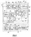
- FIG. 4is a schematic diagram of another embodiment of an EMG separating circuit of the EMG signal processing system shown in FIG. 2;
- FIG. 5Ais a graphical illustration of voltage versus time for a measured EMG signal and switch control signals produced by the EMG separating circuits of the present invention
- FIG. 5Bis a graphical illustration of voltage versus time produced by a fast signal processor, a first slow signal processor, and a second slow signal processor of the present invention
- FIG. 5Cis a graphical illustration of voltage versus time for model EMG signals produced in accordance with the present invention.
- FIGS. 6A-6Care enlarged views of portions of the graphical illustrations of FIGS. 5A-5C, respectively, between times t 0 -t 17 ;
- FIG. 7is a schematic diagram of another embodiment of an EMG separating circuit of the EMG signal processing system shown in FIG. 2 .
- a normal human 2has an esophagus 4 that extends between a mouth 6 and a stomach 8 .
- a normal humanalso has a diaphragm 10 that is shown as a disk in FIG. 1 for simplicity of illustration.
- diaphragm 10receives from the nervous system of the patient, i.e., the phrenic nerve, a neural impulse that causes diaphragm 10 to contract and relax in a manner well known in the art. Contraction of the diaphragm can be detected by measuring the electromyographic (EMG) signals generated by the diaphragm during contraction.
- EMGelectromyographic
- electrodes 12 a and 12 bare preferably positioned in esophagus 4 with one electrode 12 a placed very close to diaphragm 10 and the other electrode 12 b placed away from the diaphragm. Electrodes 12 a and 12 b are connected to an EMG signal processing system 14 disposed outside patient 2 .
- electrodes 16 a and 16 bwhich are shown in phantom in FIG. 1, are attached at or near the surface of the patient parallel and as close as possible to diaphragm 10 and connected to EMG signal processing system 14 .
- surface electrodes 16 a and 16 bare disposed on the patient such that one electrode is near the diaphragm and one electrode is spaced therefrom.
- electrodes 12 a, 12 b and 16 a, 16 bdetect the EMG signal produced by diaphragm 10 , as well as other electrical signals in the body, such as the patient's electrocardiogram (ECG) signal and noise.
- EMGelectrocardiogram
- noisecan include motion artifacts associated with the sensors and/or EMG signals from other muscles, e.g., the intercostal muscles.
- a measured EMG signal 17 from electrodes 12 a and 12 bare provided to EMG signal processing system 14 .
- a measured EMG signal 17 ′ from electrodes 16 a and 16 bare provided to EMG signal processing system 14 .
- the present inventionillustrates measured EMG signals 17 , 17 ′ as being measured by electrode pairs 12 a, 12 b within the patient or by electrode pairs 16 a, 16 b outside the patient, it is to be understood that these configurations and locations are not exclusive. On the contrary, the present invention contemplates providing electrodes at any location on the patient so long as they detect the EMG signal of interest, such as the diaphragm EMG signal. For example, one electrode in the electrode pair can be provided within the patient and the other electrode in that pair provided can be outside the patient.
- any electrodes provided in, on, or near the patient to detect the diaphragm EMGwill also detect noise, most notably the patient's ECG signals, due the relatively close location of the heart and diaphragm in a normal patient.
- Ventilator 18is a device that supplies a breathing gas, such as air, to an airway of patient 2 during inhalation and controls release of air from patient 2 during exhalation.
- Patient interface device 20such as a nasal and/or oral mask, trachea tube, or endotracheal tube, connects ventilator 18 with the patient's airway, such as the nose (as shown) and/or mouth.
- patient interface device 20is a mask provided around the nose and/or mouth of the patient to define a seal between against the patient so that breathing gas can be non-invasively delivered to the airway of the patient.
- ventilatorcan be any conventional ventilator that communicates with the airway of a patient using any conventional technique, such as the two-limb, pressure or volume, invasive ventilation systems that deliver breathing gas via a intubation tube or trachea tube.
- EMG signal processing system 14receives measured EMG signal 17 from electrodes 12 a, 12 b and/or 16 a, 16 b, generates, and supplies to ventilator 18 an amplified model diaphragm EMG signal 19 that corresponds to the diaphragm EMG signal received at diaphragm 10 .
- the amplified model diaphragm EMG signal 19is used to synchronize the operation of ventilator with the patient's breathing cycle so that the application of an inspiratory pressure or flow by the ventilator is synchronized with the inspiratory effort of the patient, and likewise, the patient's expiration is synchronized to the expiratory cycle of the ventilator.
- the present inventioncontemplates a variety of other uses for the model diaphragm EMG signal 19 , in addition to or instead of using this signal to control a ventilator.
- Other uses for diaphragm EMG signalare well known to those skilled in the art, and include, for example, monitoring the patient pulmonary function and/or measuring physiological parameters. Information gathered from the diaphragm EMG signal or other EMG signals can be used to set the control or operating parameters for a medical device, such as a ventilator.
- the EMG signalscan also be used to control the application of electrical stimulation to the upper airway muscles and/or nerves to treat obstructive sleep apnea.
- the present inventionis not limited to these uses for the EMG signals, and, in particular, the diaphragm EMG signal. Rather, the present invention is directed to the generation of a clean EMG signal from raw a EMG signal performed by the EMG signal processing system. Therefore, the present invention can be used in conjunction with any EMG signal and the resulting clean EMG signal can be used for any purpose.
- the use of a diaphragm EMG signal to control and/or augment the control of a ventilatoris provided for the purpose of illustration.
- EMG signal processing system 14isolates a model diaphragm EMG signal 19 from measured EMG signal 17 that includes the patient's diaphragm EMG signal, ECG signal and noise.
- EMG signal processing system 14includes an amplifier 22 that receives the measured EMG signal 17 , 17 ′ from electrodes 12 a, 12 b and/or 16 a, 16 b and amplifies the measured EMG signal 17 , 17 ′.
- amplifier 22has a gain of about 100.
- Amplifier 22supplies an amplified EMG signal to a low pass filter 24 .
- Low pass filter 24filters the amplified EMG signal to produce a low pass filtered signal that is, in turn, supplied to a high pass filter 26 .
- the low pass filter 24preferably has a crossover frequency of about 1.6 kHz and an attenuation of about ⁇ 12 db/octave.
- High pass filter 26filters the low pass filtered signal from the low pass filter 24 and supplies to amplifier 28 a high pass filtered signal.
- high pass filter 26has a crossover frequency of about 0.1 Hz and an attenuation of about ⁇ 12 db/octave.
- Low pass filter 24 and high pass filter 26effectively form a band pass filter having a band pass frequency between about 0.1 Hz and 1.6 kHz.
- the present inventioncontemplates replacing the combination of low pass filter 24 and high pass filter 26 with a single band pass filter having similar pass bands.
- Amplifier 28amplifies the high pass filtered signal from high pass filter 26 and supplies the amplified high pass filtered signal to a high pass filter 30 .
- amplifier 28has a gain of about 100.
- High pass filter 30filters the amplified high pass filtered signal from amplifier 28 and supplies a processed EMG signal 34 to an EMG separating circuit 32 . The details of EMG separating circuit 32 and how it operates on processed EMG signal 34 are discussed hereinafter.
- high pass filter 30has a crossover frequency of about 24 Hz and an attenuation of about ⁇ 24 db/octave.
- EMG separating circuit 32operating in combination with a moving average circuit 36 , produce, from the processed EMG signal 34 , a model diaphragm EMG signal 37 , which is supplied to an amplifier 38 .
- Moving average circuit 36produces the model diaphragm EMG signal 37 as a function of a moving average of the signal received from the EMG separating circuit 32 .
- Amplifier 38amplifies model diaphragm EMG signal 37 to produce amplified model diaphragm EMG signal 19 , which, according to one embodiment of the present invention, is supplied to ventilator 18 .
- Model diaphragm EMG signal 37 and, hence, amplified model diaphragm EMG signal 19are representations of the patient's diaphragm EMG signal.
- amplifier 38has a gain between about 1 and 10.
- measured EMG signal 17 , 17 ′is processed by amplifiers 22 and 28 and filters 24 , 26 and 30 to produce processed EMG signal 34 . It is to be understood, however, that the present invention contemplates providing measured EMG signal 17 , 17 ′ directly to the EMG separating circuit 32 .
- EMG separating circuit 32is described as receiving processed EMG signal 34 . However, it should be understood that EMG separating circuit 32 can receive measured EMG signal 17 , 17 ′. It can thus be appreciated that processed EMG signal 34 received by the EMG separating circuit 32 corresponds to measured EMG signal 17 , 17 ′ including the amplification and filtering provided by amplifiers 22 and 28 and filters 24 , 26 and 30 , respectively.
- EMG separating circuit 32includes a logic signal processor 40 and a first envelope processor 42 .
- Logic signal processor 40includes a second envelope processor 44 , a fast signal processor 46 , a first slow signal processor 48 , and a first comparator 50 .
- Logic signal processor 40receives processed EMG signal 34 from high pass filter 30 and produces therefrom a switch control or logic signal 52 .
- EMG separating circuit 32includes a first switch 54 having a control input connected to receive switch control signal 52 from first comparator 50 .
- First switch 54is configured to connect processed EMG signal 34 and first envelope processor 42 when switch control signal 52 is asserted and to isolate processed EMG signal 34 and first envelope processor 42 when the switch control signal 52 is deasserted.
- assertedand “deasserted” correspond to a binary logic state of 1 and 0 for a positive logic convention and to a logic state of 0 and 1 for a negative logic convention, respectively.
- assertedand “deasserted” are used in connection with a positive logic convention. However, this is not to be construed as limiting the present invention, which can also use a negative logic convention.
- EMG separating circuit 32also includes a second switch 56 having a control input connected to receive switch control signal 52 from first comparator 50 .
- Second switch 56is configured to connect first envelope processor 42 and moving average circuit 36 when switch control signal 52 is asserted and to isolate first envelope processor 42 and moving average circuit 36 when the switch control signal 52 is deasserted.
- First envelope processor 42includes a first high pass filter 58 , which filters processed EMG signal 34 to produce therefrom a first high pass signal, which is supplied to a first full-wave rectifier 60 .
- first high pass filter 58has a crossover frequency of about 24 Hz and an attenuation of approximately ⁇ 24 db/octave.
- First full-wave rectifier 60rectifies the first high pass signal to produce a first rectified signal that is supplied to a first low pass filter 62 .
- First low pass filter 62filters the first rectified signal to produce a first low pass or first envelope signal that is supplied to moving average circuit 36 through second switch 56 .
- first low pass filter 62has a crossover frequency of about 16 Hz and an attenuation of approximately ⁇ 6 db/octave.
- Processed EMG signal 34typically has voltage excursions above and below a ground or neutral reference.
- First high pass filter 58 , first full-wave rectifier 60 and first low pass filter 62 of first envelope processor 42coact to produce from processed EMG signal 34 a first envelope signal 61 having voltage excursions to one side of a ground or neutral reference G.
- second envelope processor 44includes a second low pass filter 64 that filters processed EMG signal 34 from high pass filter 30 .
- Second low pass filter 64filters processed EMG signal 34 to produce a second low pass signal, which is supplied to a second full-wave rectifier 66 .
- second low pass filter 64has a crossover frequency of approximately 16 Hz and an attenuation of approximately ⁇ 6 db/octave.
- Second full-wave rectifier 66rectifies the second low pass signal to produce a second rectified or second envelope signal.
- Second low pass filter 64 and second full-wave rectifier 66 of second envelope processor 44coact to produce from processed EMG signal 34 a second envelope signal 67 having voltage excursions to one side of ground or a neutral reference G.
- Fast signal processor 46includes a third low pass filter 68 that filters the second rectified or second envelope signal from second full-wave rectifier 66 to produce a third low pass signal that is supplied to a first amplifier 70 .
- third low pass filter 68has a crossover frequency of approximately 7 Hz and an attenuation of approximately ⁇ 6 db/octave.
- First amplifier 70amplifies the third low pass signal to produce a first amplified signal that is supplied to a fourth low pass filter 72 .
- first amplifier 70has a gain less than unity and is biased to shift the level of the first amplified signal relative to a ground or neutral reference 100 , shown best in FIG. 6 B.
- Fourth low pass filter 72filters the first amplified signal to produce a fourth low pass signal that is supplied to a combiner 74 , which is also connected to receive the third low pass signal from third low pass filter 68 .
- fourth low pass filter 72has a crossover frequency of approximately 0.16 Hz and an attenuation of approximately ⁇ 12 db/octave.
- Combiner 74combines the third low pass signal and the fourth low pass signal to produce a fast signal 76 , perhaps shown best in FIG. 6 B. More specifically, combiner 74 subtracts the fourth low pass signal from the third low pass signal to produce fast signal 76 .
- first slow signal processor 48includes a second amplifier 78 that receives second rectified or second envelope signal 67 from second full-wave rectifier 66 .
- Second amplifier 78amplifies the second rectified or second envelope signal to produce a second amplified signal that is provided to a fifth low pass filter 80 .
- second amplifier 78has a gain greater than unity.
- second amplifier 78does not shift the level of the second amplified signal relative to a ground or a neutral reference 102 , shown best in FIG. 6 B.
- Fifth low pass filter 80filters the second amplified signal to produce a first slow signal 82 , shown best in FIG. 6 B.
- fifth low pass filter 80has a crossover frequency of approximately 1.8 Hz and an attenuation of approximately ⁇ 12 db/octave.
- First comparator 50includes a pair of inputs that receive fast signal 76 from fast signal processor 46 and first slow signal 82 from first slow signal processor 48 .
- first comparator 50has an inverting input that receives fast signal 76 and a non-inverting input that receives first slow signal 82 .
- Comparator 50compares fast signal 76 and first slow signal 82 in a manner known in the art and produces, as a function of the comparison, switch control signal 52 , which is asserted when first slow signal 82 is greater than fast signal 76 , and which is deasserted when first slow signal 82 is less than fast signal 76 .
- EMG separating circuit 32 and moving average circuit 36coact to produce model diaphragm EMG signal 37 , shown best in FIG. 6 C.
- the operation of EMG separating circuit 32 and moving average circuit 36are described below following a description of an alternative embodiment of EMG separating circuit 32 ′, which is shown in FIG. 4 .
- an EMG separating circuit 32 ′includes first envelope processor 42 and a logic signal processor 40 ′, which includes second envelope processor 44 , fast signal processor 46 , first slow signal processor 48 and first comparator 50 .
- Logic signal processor 40 ′also includes a second slow signal processor 86 and a comparer 88 .
- Comparer 88includes first comparator 50 , a second comparator 90 and a logic gate 92 , preferably an AND gate.
- Second slow signal processor 86includes a sixth low pass filter 94 , which is configured to receive the second amplified signal from second amplifier 78 , and a third switch 96 having a control input connected to the output of first comparator 50 .
- Third switch 96is configured to connect the second amplified signal to sixth low pass filter 94 when a first comparator signal produced at an output of first comparator 50 is asserted. Similarly, third switch 96 is configured to isolate the second amplified signal from sixth low pass filter 94 when the first comparator signal is deasserted. When the first comparator signal is asserted, sixth low pass filter 94 filters the second amplified signal to produce a second slow signal 98 , shown best in FIG. 6 B.
- the first comparator 50has as its inverting input, fast signal 76 from combiner 74 and has as its non-inverting input, first slow signal 82 from fifth low pass filter 80 .
- Second comparator 90has a non-inverting input connected to receive fast signal 76 from combiner 74 and a non-inverting input connected to receive second slow signal 98 from sixth low pass filter 94 .
- First comparator 50compares fast signal 76 and first slow signal 82 to produce a first comparator signal 89 , which is asserted when first slow signal 82 is greater than fast signal 76 , and which is deasserted when first slow signal 82 is less than a value of fast signal 76 .
- second comparator 90produces on an output thereof a second comparator signal 91 , which is asserted when second slow signal 98 is greater than fast signal 76 and which is deasserted when second slow signal 98 is less than fast signal 76 .
- Logic gate 92logically combines first comparator signal 89 and the second comparator signal 91 to produce a switch control or logic signal 52 ′, which is supplied to first and second switches 54 and 56 .
- switch control signal 52 ′is asserted when first and second comparator signals 89 and 91 are asserted and is deasserted when one or both of first and second comparator signals 89 and 91 are deasserted.
- EMG separating circuit 32 ′ and the moving average circuit 36coact to produce a model diaphragm EMG signal 37 ′.
- EMG separating circuit 32 ′The operation of EMG separating circuit 32 ′ is described hereafter with reference to FIGS. 5A-5C and 6 A- 6 C, and with continuing reference to FIG. 4 .
- processed EMG signal 34 received by EMG separating circuits 32 ′includes an electrocardiogram (ECG) signal having cycles ECG 1 -ECG 8 .
- ECGelectrocardiogram
- FIG. 5Bshows fast signal 76 , first slow signal 82 , and second slow signal 98 generated by fast signal processor 46 , first slow signal processor 48 , and second slow signal processor 86 , respectively, in response to based on processed EMG signal 34 .
- first and second comparators 50 and 90 and logic gate 92 of comparer 88coact to produce on the output of logic gate 92 switch control signal 52 ′, shown best in FIG. 5A, which controls switching of first and second switches 54 and 56 .
- the first envelope processor 42 and the moving average circuit 36coact to produce the model diaphragm EMG signal 37 ′, shown best in FIG. 6 C.
- FIGS. 6A-6Cshow enlarged views of the signals shown in FIGS. 5A-5C, respectively, between times to and t 17 .
- FIG. 6Ashows the ECG 3 and the ECG 4 cycles of processed EMG signal 34 .
- the ECG 3 and ECG 4 cycleseach include a P wave component, a QRS complex and a T wave component.
- fast signal 76has a ground reference 100 which is shifted from, preferably below, ground reference 102 for first and second slow signals 82 and 98 .
- first amplifier 70produces this shift, which adjusts the interval during which first switch control signal 52 ′ is asserted or deasserted.
- processed EMG signal 34is relatively constant around ground reference G.
- fast signal 76is at its ground reference 100 and first and second slow signals 82 and 98 are at their ground reference 102 .
- ground reference 100is less than ground reference 102
- first comparator signal 89is asserted
- second comparator signal 91is asserted
- switch control signal 52 ′is asserted.
- the processed EMG signal 34increases in response to an increase in the P wave of the ECG 3 cycle.
- fast signal processor 46enables signals having a fast rate of change, or slew rate, to pass therethrough, fast signal 76 increases above the first and second slow signals 82 and 98 .
- first comparator signal 89 , the second comparator signal 91 and switch control signal 52 ′change from asserted to deasserted at time t 1 .
- third switch 96opens, thereby isolating sixth low pass filter 94 from the second amplified signal produced by second amplifier 78 .
- first and second switches 54 and 56open, thereby isolating first envelope processor 42 from processed EMG signal 34 and moving average circuit 36 .
- fast signal 76decreases below first and second slow signals 82 and 98 in response to the P wave decreasing toward its ground reference G.
- first and second comparator signals 89 and 91change from deasserted to asserted and third switch 96 closes, thereby connecting sixth low pass filter 94 to receive the second amplified signal from second amplifier 78 .
- switch control signal 52 ′changes from deasserted to asserted, thereby causing first and second switches 54 and 56 to close and connect the first envelope processor 42 to processed EMG signal 34 and to connect moving average circuit 36 to first envelope signal 61 output from first envelope processor 42 .
- first envelope processor 42 and the moving average circuit 36coact to produce model diaphragm EMG signal 37 ′, which varies as a function of the processed EMG signal 34 . More specifically, when switch control signal 52 ′ is asserted, moving average circuit 36 produces model diaphragm EMG signal 37 ′ that varies as a function of a moving average of first envelope signal 61 produced by first envelope processor 42 . In contrast, when the switch control signal 52 ′ is deasserted, first envelope processor 42 is isolated from processed EMG signal 34 and moving average circuit 36 .
- moving average circuit 36operates as a sample-and-hold to produce model diaphragm EMG signal 37 ′ having a set value corresponding to a value of the moving average of the first envelope signal when switch control signal 52 ′ changes from asserted to deasserted.
- first low pass filter 62operates as a sample-and-hold to produce a set value for the first envelope signal.
- switch control signal 52 ′changes from deasserted to asserted
- first and second switches 54 and 56close and connect first envelope processor 42 to processed EMG signal 34 and to connect first envelope signal 61 output from first envelope processor 42 to moving average circuit 36 .
- first envelope signal 61initiates changing from its set value as a function of processed EMG signal 34
- moving average circuit 36causes the model diaphragm EMG signal 37 ′ to change as a function of the first envelope signal.
- Logic signal processor 40 ′controls the state of switch control signal 52 ′ so that when processed EMG signal 34 is changing rapidly due to the ECG signal and/or noise, first envelope signal 61 is not contributing to model diaphragm EMG signal 37 ′. In contrast, when processed EMG signal 34 is not changing rapidly due to the ECG signal and/or noise, model diaphragm EMG signal 37 ′ varies as a function of first envelope signal 61 which varies as a function of processed EMG signal 34 .
- fast signal 76increases above first and second slow signals 82 and 98 in response to a decrease of processed EMG signal 34 .
- first and second comparator signals 89 and 91 and switch control signal 52 ′change from asserted to deasserted.
- moving average circuit 36In response to the switch control signal 52 ′ changing from asserted to deasserted, moving average circuit 36 generates model diaphragm EMG signal 37 ′ having a set value which corresponds to the moving average of first envelope signal 61 when switch control signal 52 ′ changes from asserted to deasserted.
- third switch 96opens and isolates sixth low pass filter 94 from the second amplified signal produced by second amplifier 78 .
- sixth low pass filter 94operates as a sample-and-hold to produce second slow signal 98 having a set value corresponding to the value of second slow signal 98 when third switch 96 opens.
- second slow signal 98is at the set value and fast signal 76 and first slow signal 82 change in response to the Q wave and the R wave of the QRS complex of the ECG 3 cycle. Because fast signal processor 46 enables fast signal 76 to change more rapidly than first slow signal 82 produced by first slow signal processor 48 , the first slow signal 82 changes, e.g., increases, but to a lesser extent than fast signal 76 between times t 3 and t 4 .
- fast signal 76decreases below the increasing first slow signal 82 .
- first comparator signal 89changes from deasserted to asserted and third switch 96 closes, thereby connecting sixth low pass filter 94 to receive the second amplified signal from second amplifier 78 .
- sixth low pass filter 94produces second slow signal 98 having a value that changes as a function of the second amplified signal. More specifically, when third switch 96 closes, second slow signal 98 initiates changing from the set value and begins converging toward first slow signal 82 .
- first slow signal 82 and second slow signal 98diverged between times t 3 and t 4 and because fifth and sixth low pass filters 80 and 94 do not permit rapid changes of first slow signal 82 and second slow signal 98 , respectively, second slow signal 98 converges gradually toward first slow signal 82 .
- fifth low pass filter 80 and sixth low pass filter 94produce first slow signal 82 and second slow signal 98 , respectively, having maximum slew rates that are less than the maximum slew rate of fast signal 76 produced by the fast signal processor 46 .
- This difference in maximum slew rateenables fast signal 76 to change more rapidly than first and second slow signals 82 and 98 in response to second envelope signal 67 .
- third, fourth, fifth and sixth low pass filters 68 , 72 , 80 and 94i.e., crossover frequency and attenuation
- the responses of fast signal 76 and first and second slow signals 82 and 98can be adapted to cause first and second comparator signals 89 and 91 to change states at desired times of an ECG cycle of an EMG signal.
- increasing the crossover frequency of fifth low pass filter 80increases the maximum slew rate of first slow signal 82 , thereby decreasing the interval during which first comparator signal 89 is deasserted after time t 3 .
- decreasing the crossover frequency of fifth low pass filter 80increases the interval during which first comparator signal 89 is deasserted after time t 3 .
- sixth low pass filter 94 and second comparator signal 91Similar comments apply with respect to sixth low pass filter 94 and second comparator signal 91 . Moreover, adjusting the maximum slew rate of fast signal 76 by adjusting the crossover frequency of third and/or fourth low pass filters 68 and 72 adjusts the response of fast signal 76 with respect to first and second slow signals 82 and 98 .
- the state of switch control signal 52 ′can be adjusted as a function of processed EMG signal 34 and, more particularly, the ECG signal of processed EMG signal 34 .
- fast signal 76decreases and second slow signal 98 increases in response to the R wave and the S wave of the ECG 3 cycle.
- second comparator signal 91changes from deasserted to asserted. Because first comparator signal 89 is asserted, when second comparator signal 89 changes from deasserted to asserted at time t 5 , switch control signal 52 ′ changes from deasserted to asserted.
- fast signal 76is less than first and second slow signals 82 and 98 and switch control signal 52 ′ is asserted in response to processed EMG signal 34 being relatively constant around the ground reference G.
- switch control signal 52 ′model diaphragm EMG signal 37 ′ varies as a function of the moving average of first envelope signal 61 .
- fast signal 76increases above second slow signal 98 , which is gradually converging toward first slow signal 82 , in response to the T wave of the ECG 3 cycle increasing from the ground reference G.
- the T wave of the ECG 3 cyclecauses fast signal 76 to be greater than second slow signal 98 , whereby second comparator signal 91 and switch control signal 52 ′ are deasserted.
- the trailing edge of the T wave of the ECG 3 cycledecreases to relatively constant around the ground reference G thereby causing fast signal 76 to converge toward its ground reference 100 and causing first and second slow signals 82 and 98 to converge toward their ground reference 102 . Because it can react more rapidly than first and second slow signals 82 and 98 , fast signal 76 converges toward its ground reference 100 more rapidly than first and second slow signals 82 and 98 converge toward their ground reference 102 . Hence, between times t 7 and t 8 , the value of fast signal 76 is below the values of first and second slow signals 82 or 98 and first and second comparator signals 89 and 91 and switch control signal 52 ′ are asserted.
- first comparator signal 89changing from deasserted to asserted at time t 4 causes second slow signal 98 to gradually converge toward first slow signal 82 .
- This gradual convergenceenables fast signal 76 between times t 6 and t 7 to be greater than second slow signal 98 and less than first slow signal 82 .
- switch control signal 52 ′is deasserted due to fast signal 76 being greater than second slow signal 98 .
- the leading edge of the P wave of the ECG 4 cyclecauses fast signal 76 to increase above first and second slow signals 82 and 98 , whereby switch control signal 52 ′ changes to deasserted.
- the trailing edge of the P wave of the ECG 4 cyclecauses fast signal 76 to decrease below the values of first and second slow signals 82 and 98 , whereby switch control signal 52 ′ changes to asserted.
- the leading edge of the QRS complexcauses fast signal 76 to increase above first and second slow signals 82 and 98 , whereby switch control signal 52 ′ changes to deasserted.
- fast signal 76increases above first and second slow signals 82 and 98 in response to the Q wave and R wave of the ECG 4 cycle.
- first and second comparator signals 89 and 91 and the switch control signal 52 ′are deasserted and first, second, and third switches 54 , 56 and 96 are opened.
- second slow signal 98is a set value corresponding to the value thereof when first comparator signal 89 changes from asserted to deasserted.
- model diaphragm EMG signal 37 ′is a set value corresponding to the value of the moving average of first envelope signal 61 when switch control signal 52 ′ changes from asserted to deasserted.
- fast signal 76decreases below first slow signal 82 in response to the trailing edge of the R wave of the ECG 4 cycle.
- first comparator signal 89changes from deasserted to asserted, thereby causing third switch 96 to close.
- second slow signal 98initiates changing from the set value and begins gradually converging toward first slow signal 82 .
- the S wave of the ECG 4 cyclecauses fast signal 76 and second slow signal 98 to converge so that at time t 12 fast signal 76 decreases below second slow signal 98 , whereby second comparator signal 91 and the switch control signal 52 ′ change to asserted.
- a leading edge of the T wave of the ECG 4 cyclecauses the value of fast signal 76 to increase above the value of second slow signal 98 .
- second comparator signal 91 and switch control signal 52 ′change to deasserted.
- fast signal 76increases above first slow signal 82 and first comparator signal 89 changes to deasserted, whereby third switch 96 opens and the value of second slow signal 98 is set at the value thereof when first comparator signal changed 89 to deasserted.
- fast signal 76decreases below first slow signal 82 and first comparator signal 89 changes to deasserted, whereby third switch 96 connects sixth low pass filter 94 to receive the second amplified signal from second amplifier 78 .
- sixth low pass filter 94causes the value of second slow signal 98 to initiate gradual changing from the set value toward first slow signal 82 .
- model diaphragm EMG signal 37 ′varies as a function of the moving average of first envelope signal 61 .
- model diaphragm EMG signal 37 ′is a set value corresponding to the moving average of first envelope signal 61 when switch control signal 52 ′ changes to deasserted.
- first comparator 50produces switch control signal 52 , shown in FIGS. 5A and 6A, to control switching of first and second switches 54 and 56 .
- the value of switch control signal 52is shifted upward from the value of switch control signal 52 ′ for illustration purposes only.
- switch control signal 52 produced by EMG separating circuit 32is asserted during portions of the S wave and/or the T wave of each ECG cycle when switch control signal 52 ′ produced by EMG separating circuit 32 ′ shown in FIG. 4 would be deasserted.
- model diaphragm EMG signal 37produced in response to operation of EMG separating circuit 32 of FIG.
- model diaphragm EMG signal 37has the same general shape as model diaphragm EMG signal 37 ′ produced in response to operation of EMG separating circuit 32 ′ of FIG. 4, model diaphragm EMG signal 37 includes more noise and ECG artifacts than model diaphragm EMG signal 37 ′ generated by EMG separating circuit 32 ′ of FIG. 4 .
- EMG separating circuit 32 ′′includes logic signal processor 40 ′ shown in FIG. 4, first envelope processor 42 shown in FIGS. 3 and 4, and a third envelope processor 104 .
- Third envelope processor 104includes a second high pass filter 106 connected to filter processed EMG signal 34 to produce a second high pass signal, which is provided to a third full-wave rectifier 108 .
- second high pass filter 106has a crossover frequency of about 100 Hz and an attenuation of about ⁇ 24 db/octave.
- Third full-wave rectifier 108rectifies the second high pass signal and provides a third rectified signal to a seventh low pass filter 110 .
- Seventh low pass filter 110filters the third rectified signal to produce a seventh low pass or third envelope signal 111 , which is provided to second switch 56 .
- seventh low pass filter 110has a crossover frequency of about 16 Hz and an attenuation of about ⁇ 6 db/octave.
- Second high pass filter 106 , third full-wave rectifier 108 , and seventh low pass filter 110coact to produce from processed EMG signal 34 , third envelope signal 111 having voltage excursions to one side of the ground or neutral reference G.
- first and second switches 54 and 56connect first envelope processor 42 to processed EMG signal 34 and moving average circuit 36 .
- first envelope processor 42is isolated from processed EMG signal 4 and moving average circuit 6 , and third envelope processor 104 is connected to moving average circuit 36 .
- EMG separating circuit 32 ′′causes moving average circuit 36 to produce a model diaphragm EMG signal 37 ′′, shown best in FIG. 6C, as a moving average of first envelope signal 61 when switch control signal 52 ′ is asserted and as a function of third envelope signal 111 when switch control signal 52 ′ is deasserted. Because it continuously processes processed EMG signal 34 via first envelope processor 42 or third envelope processor 104 , moving average circuit 36 does not operate as a sample-and-hold when first envelope processor 42 is isolated therefrom, i.e., when switch control signal is deasserted.
- model diaphragm EMG signal 37 ′′has a more continuous slope, with less stairstepping, i.e., relatively rapid variations, than model diaphragm EMG signals 37 and 37 ′ produced by the EMG separating circuits 32 and 32 ′ of FIGS. 3 and 4, respectively.
- FIG. 5Cshows model diaphragm EMG signals 37 , 37 ′ and 37 ′′ for one inhalation before time t 17 and one exhalation after time t 17 .
- model diaphragm EMG signals 37 , 37 ′ and 37 ′′are at a relatively steady state around a ground or neutral reference 112 .
- ventilator 18detects the slope of model diaphragm EMG signals 37 , 37 ′ or 37 ′′ received thereby and controls the supply of air to patient 2 as a function of the detected slope.
- ventilator 18urges air into the lungs of patient 2 in response to detecting a positive slope of one of the model diaphragm EMG signals 37 , 37 ′ or 37 ′′′.
- ventilator 18terminates urging air into the lungs of the patient, enabling air to escape from the lungs due to relaxation of diaphragm 10 and the natural elastic properties of the thorax.
- model diaphragm EMG signals 37 , 37 ′ or 37 ′′in any conventional manner to control a ventilator, and is not intended to be limited to the above description one exemplary embodiment of the to invention.
- the present inventionprovides an apparatus and method for separating a model diaphragm EMG signal 37 , 37 ′, 37 ′′ from a measured EMG signal 17 , which includes the patient's diaphragm signal, ECG signal, and other noise.
- Model diaphragm EMG signal 37 , 37 ′, 37 ′′can be amplified to produce an amplified model diaphragm EMG signal 19 , which can be used to control the operation of a respirator in a manner that avoids patient discomfort.
- the present inventionprovides a low cost, analog circuit that is capable of providing a model of a patient's diaphragm EMG signal simultaneously as it is being acquired.
- the circuitincludes analog filtering, sensing the presence of and blocking of the P wave, QRS complex and T wave of an ECG cycle of the patient's EMG signal, full-wave rectifying of the remaining signal and creating its moving average with interpolation for the P wave, QRS complex and T wave of each ECG cycle.
Landscapes
- Health & Medical Sciences (AREA)
- Life Sciences & Earth Sciences (AREA)
- General Health & Medical Sciences (AREA)
- Animal Behavior & Ethology (AREA)
- Veterinary Medicine (AREA)
- Biomedical Technology (AREA)
- Heart & Thoracic Surgery (AREA)
- Engineering & Computer Science (AREA)
- Public Health (AREA)
- Hematology (AREA)
- Emergency Medicine (AREA)
- Pulmonology (AREA)
- Anesthesiology (AREA)
- Physics & Mathematics (AREA)
- Biophysics (AREA)
- Pathology (AREA)
- Medical Informatics (AREA)
- Molecular Biology (AREA)
- Surgery (AREA)
- Measurement And Recording Of Electrical Phenomena And Electrical Characteristics Of The Living Body (AREA)
Abstract
Description
Claims (36)
Priority Applications (1)
| Application Number | Priority Date | Filing Date | Title |
|---|---|---|---|
| US09/567,795US6411843B1 (en) | 1999-05-28 | 2000-05-09 | Method and apparatus for producing a model EMG signal from a measured EMG signal |
Applications Claiming Priority (2)
| Application Number | Priority Date | Filing Date | Title |
|---|---|---|---|
| US13655199P | 1999-05-28 | 1999-05-28 | |
| US09/567,795US6411843B1 (en) | 1999-05-28 | 2000-05-09 | Method and apparatus for producing a model EMG signal from a measured EMG signal |
Publications (1)
| Publication Number | Publication Date |
|---|---|
| US6411843B1true US6411843B1 (en) | 2002-06-25 |
Family
ID=26834410
Family Applications (1)
| Application Number | Title | Priority Date | Filing Date |
|---|---|---|---|
| US09/567,795Expired - LifetimeUS6411843B1 (en) | 1999-05-28 | 2000-05-09 | Method and apparatus for producing a model EMG signal from a measured EMG signal |
Country Status (1)
| Country | Link |
|---|---|
| US (1) | US6411843B1 (en) |
Cited By (91)
| Publication number | Priority date | Publication date | Assignee | Title |
|---|---|---|---|---|
| GB2384566A (en)* | 2002-01-15 | 2003-07-30 | Gen Electric | Processing EMG signals using Linear Predictive Modelling |
| US20030188748A1 (en)* | 1998-06-04 | 2003-10-09 | Christer Sinderby | Automatic adjustment of applied levels of ventilatory support and extrinsic peep by closed-loop control of neuro-ventilatory efficiency |
| US20040044377A1 (en)* | 2002-08-28 | 2004-03-04 | Siemens Elema Ab | Nerve stimulation device |
| US20040181161A1 (en)* | 2003-02-20 | 2004-09-16 | Addington W. Robert | Apparatus for evaluating a patient's laryngeal cough reflex and associated methods |
| US20040210172A1 (en)* | 2002-10-25 | 2004-10-21 | Revivant Corporation | Method of estimating the actual ECG of a patient during CPR |
| WO2005048839A1 (en)* | 2003-11-19 | 2005-06-02 | Maquet Critical Care Ab | Method and apparatus for determining an emg signal |
| US20050159659A1 (en)* | 2004-01-16 | 2005-07-21 | Mohamad Sawan | Catheter for transdiaphragmatic pressure and diaphragm electromyogram recording using helicoidal electrodes |
| US20050211246A1 (en)* | 2004-03-25 | 2005-09-29 | Maquet Critical Care Ab | Method and device responsive to diaphragmatic activity for adjusting positive pressure assist during expiration |
| US6962155B1 (en)* | 1999-07-30 | 2005-11-08 | Universite De Montreal | Target drive ventilation gain controller and method |
| US20070107725A1 (en)* | 2004-02-20 | 2007-05-17 | Pneumoflex Systems, Llc | Intra-Oral Nebulizer With Rainfall Chamber |
| US20070137648A1 (en)* | 2005-12-16 | 2007-06-21 | Pneumoflex Systems, Llc | Intraoral Nebulizer Providing Air Curtains |
| US20070163572A1 (en)* | 2004-02-20 | 2007-07-19 | Addington W R | Intra-oral nebulizer |
| KR100791883B1 (en) | 2004-02-17 | 2008-01-07 | 재단법인 산재의료관리원 | EMG-controlled electric wheelchair and its control method |
| FR2903314A1 (en)* | 2006-07-10 | 2008-01-11 | Univ Paris Curie | DEVICE FOR DETECTING INAPPROPRIATE ADJUSTMENT OF A VENTILATORY ASSISTANCE MACHINE USED ON A MAMMAL. |
| US20080078388A1 (en)* | 2006-09-29 | 2008-04-03 | Nellcor Puritan Bennett Incorporated | Patient interface having an integrated system for communicating data to a ventilator |
| US20080200966A1 (en)* | 2005-06-09 | 2008-08-21 | Urban Blomberg | Simulator For Use With a Breathing-Assist Device |
| WO2008131798A1 (en)* | 2007-04-27 | 2008-11-06 | Maquet Critical Care Ab | An emg controlled ventilator and a method for an emg controlled ventilator |
| US20080308104A1 (en)* | 2005-06-09 | 2008-12-18 | Urban Blomberg | Ventilator |
| WO2009082295A1 (en)* | 2007-12-20 | 2009-07-02 | Maquet Critical Care Ab | A computer program product, a control unit for a ventilator, a ventilator and a method for use with a ventilator |
| EP1711104A4 (en)* | 2004-01-16 | 2009-07-15 | Compumedics Ltd | Method and apparatus for ecg-derived sleep disordered breathing monitoring, detection and classification |
| US20100081119A1 (en)* | 2008-09-30 | 2010-04-01 | Nellcor Puritan Bennett Llc | Configurable respiratory muscle pressure generator |
| US20110105936A1 (en)* | 2004-02-20 | 2011-05-05 | Pneumoflex Systems, Llc | Nebulizer having flow meter function |
| US20120240934A1 (en)* | 2011-03-21 | 2012-09-27 | Holzrichter John F | System for controlling apena |
| US20130213399A1 (en)* | 2012-02-22 | 2013-08-22 | Drager Medical Gmbh | Respiration system |
| US8671934B2 (en) | 2011-01-20 | 2014-03-18 | Pneumoflex Systems, Llc | Nebulizer that is activated by negative inspiratory pressure |
| US20140142395A1 (en)* | 2011-04-12 | 2014-05-22 | Frank Sattler | Apparatus and method for data processing of physiological signals |
| US8825148B2 (en) | 2012-01-25 | 2014-09-02 | Siemens Medical Solutions Usa, Inc. | System for monitoring and diagnosis of cardiac electrogram signals using multi-dimensional analysis |
| US9022027B2 (en) | 2004-02-20 | 2015-05-05 | Pneumoflex Systems, Llc | Nebulizer with intra-oral vibrating mesh |
| US20150366480A1 (en)* | 2014-06-20 | 2015-12-24 | Dräger Medical GmbH | Signal processing unit of an emg measuring system |
| US20160100808A1 (en)* | 2014-10-08 | 2016-04-14 | Keivan Anbarani | System and method for respiratory system assessment |
| US9452274B2 (en) | 2011-01-20 | 2016-09-27 | Pneumoflex Systems, Llc | Metered dose atomizer |
| US9452270B2 (en) | 2011-01-20 | 2016-09-27 | Pneumoflex Systems, Llc | Nebulizer having replaceable nozzle assembly and suction line |
| US10010259B2 (en) | 2015-05-01 | 2018-07-03 | Advancer Technologies, Llc | EMG circuit |
| EP3381354A1 (en)* | 2017-03-31 | 2018-10-03 | Koninklijke Philips N.V. | Methods and system for processing an emg signal |
| US20190223748A1 (en)* | 2018-01-25 | 2019-07-25 | Ctrl-Labs Corporation | Methods and apparatus for mitigating neuromuscular signal artifacts |
| US10406345B2 (en) | 2015-10-16 | 2019-09-10 | Zoll Medical Corporation | Dual sensor electrodes for providing enhanced resuscitation feedback |
| US10489986B2 (en) | 2018-01-25 | 2019-11-26 | Ctrl-Labs Corporation | User-controlled tuning of handstate representation model parameters |
| US10496168B2 (en) | 2018-01-25 | 2019-12-03 | Ctrl-Labs Corporation | Calibration techniques for handstate representation modeling using neuromuscular signals |
| US10504286B2 (en) | 2018-01-25 | 2019-12-10 | Ctrl-Labs Corporation | Techniques for anonymizing neuromuscular signal data |
| US10592001B2 (en) | 2018-05-08 | 2020-03-17 | Facebook Technologies, Llc | Systems and methods for improved speech recognition using neuromuscular information |
| US10639234B2 (en) | 2015-10-16 | 2020-05-05 | Zoll Circulation, Inc. | Automated chest compression device |
| US10656711B2 (en) | 2016-07-25 | 2020-05-19 | Facebook Technologies, Llc | Methods and apparatus for inferring user intent based on neuromuscular signals |
| US10682282B2 (en) | 2015-10-16 | 2020-06-16 | Zoll Circulation, Inc. | Automated chest compression device |
| US10684692B2 (en) | 2014-06-19 | 2020-06-16 | Facebook Technologies, Llc | Systems, devices, and methods for gesture identification |
| JP2020517324A (en)* | 2017-04-20 | 2020-06-18 | コーニンクレッカ フィリップス エヌ ヴェKoninklijke Philips N.V. | Method and system for detecting inhalation and extracting the amount of neurorespiratory drive from an EMG signal |
| US10687759B2 (en) | 2018-05-29 | 2020-06-23 | Facebook Technologies, Llc | Shielding techniques for noise reduction in surface electromyography signal measurement and related systems and methods |
| US10772519B2 (en) | 2018-05-25 | 2020-09-15 | Facebook Technologies, Llc | Methods and apparatus for providing sub-muscular control |
| US10817795B2 (en) | 2018-01-25 | 2020-10-27 | Facebook Technologies, Llc | Handstate reconstruction based on multiple inputs |
| US10842407B2 (en) | 2018-08-31 | 2020-11-24 | Facebook Technologies, Llc | Camera-guided interpretation of neuromuscular signals |
| US10874583B2 (en) | 2017-04-20 | 2020-12-29 | Zoll Circulation, Inc. | Compression belt assembly for a chest compression device |
| US10905836B2 (en) | 2015-04-02 | 2021-02-02 | Hill-Rom Services Pte. Ltd. | Manifold for respiratory device |
| US10905383B2 (en) | 2019-02-28 | 2021-02-02 | Facebook Technologies, Llc | Methods and apparatus for unsupervised one-shot machine learning for classification of human gestures and estimation of applied forces |
| US10905629B2 (en) | 2018-03-30 | 2021-02-02 | Zoll Circulation, Inc. | CPR compression device with cooling system and battery removal detection |
| US10921764B2 (en) | 2018-09-26 | 2021-02-16 | Facebook Technologies, Llc | Neuromuscular control of physical objects in an environment |
| US10937414B2 (en) | 2018-05-08 | 2021-03-02 | Facebook Technologies, Llc | Systems and methods for text input using neuromuscular information |
| US10970936B2 (en) | 2018-10-05 | 2021-04-06 | Facebook Technologies, Llc | Use of neuromuscular signals to provide enhanced interactions with physical objects in an augmented reality environment |
| US10967142B1 (en)* | 2017-09-20 | 2021-04-06 | ART MEDICAL Ltd. | Systems and methods for tracking spontaneous breathing in a mechanically ventilated patient |
| US10970374B2 (en) | 2018-06-14 | 2021-04-06 | Facebook Technologies, Llc | User identification and authentication with neuromuscular signatures |
| WO2021063601A1 (en) | 2019-10-02 | 2021-04-08 | Drägerwerk AG & Co. KGaA | Method and device for determining a respiratory and/or cardiogenic signal |
| US10990174B2 (en) | 2016-07-25 | 2021-04-27 | Facebook Technologies, Llc | Methods and apparatus for predicting musculo-skeletal position information using wearable autonomous sensors |
| US11000211B2 (en) | 2016-07-25 | 2021-05-11 | Facebook Technologies, Llc | Adaptive system for deriving control signals from measurements of neuromuscular activity |
| US11045137B2 (en) | 2018-07-19 | 2021-06-29 | Facebook Technologies, Llc | Methods and apparatus for improved signal robustness for a wearable neuromuscular recording device |
| US11069148B2 (en) | 2018-01-25 | 2021-07-20 | Facebook Technologies, Llc | Visualization of reconstructed handstate information |
| US11079846B2 (en) | 2013-11-12 | 2021-08-03 | Facebook Technologies, Llc | Systems, articles, and methods for capacitive electromyography sensors |
| US11179066B2 (en) | 2018-08-13 | 2021-11-23 | Facebook Technologies, Llc | Real-time spike detection and identification |
| US11216069B2 (en) | 2018-05-08 | 2022-01-04 | Facebook Technologies, Llc | Systems and methods for improved speech recognition using neuromuscular information |
| US11246795B2 (en) | 2017-04-20 | 2022-02-15 | Zoll Circulation, Inc. | Compression belt assembly for a chest compression device |
| US11331045B1 (en) | 2018-01-25 | 2022-05-17 | Facebook Technologies, Llc | Systems and methods for mitigating neuromuscular signal artifacts |
| US11337652B2 (en) | 2016-07-25 | 2022-05-24 | Facebook Technologies, Llc | System and method for measuring the movements of articulated rigid bodies |
| US11481031B1 (en) | 2019-04-30 | 2022-10-25 | Meta Platforms Technologies, Llc | Devices, systems, and methods for controlling computing devices via neuromuscular signals of users |
| US11481030B2 (en) | 2019-03-29 | 2022-10-25 | Meta Platforms Technologies, Llc | Methods and apparatus for gesture detection and classification |
| US11493993B2 (en) | 2019-09-04 | 2022-11-08 | Meta Platforms Technologies, Llc | Systems, methods, and interfaces for performing inputs based on neuromuscular control |
| US20230001117A1 (en)* | 2021-06-18 | 2023-01-05 | Drägerwerk AG & Co. KGaA | Device, process and computer program for determining a patient component |
| US11567573B2 (en) | 2018-09-20 | 2023-01-31 | Meta Platforms Technologies, Llc | Neuromuscular text entry, writing and drawing in augmented reality systems |
| US11583218B2 (en) | 2019-11-20 | 2023-02-21 | Advancer Technologies, Llc | EMG device |
| US11635736B2 (en) | 2017-10-19 | 2023-04-25 | Meta Platforms Technologies, Llc | Systems and methods for identifying biological structures associated with neuromuscular source signals |
| US11644799B2 (en) | 2013-10-04 | 2023-05-09 | Meta Platforms Technologies, Llc | Systems, articles and methods for wearable electronic devices employing contact sensors |
| US11666264B1 (en) | 2013-11-27 | 2023-06-06 | Meta Platforms Technologies, Llc | Systems, articles, and methods for electromyography sensors |
| CN116236212A (en)* | 2022-08-05 | 2023-06-09 | 华南师范大学 | Diaphragm myoelectric noise reduction method, system, device and storage medium |
| US11797087B2 (en) | 2018-11-27 | 2023-10-24 | Meta Platforms Technologies, Llc | Methods and apparatus for autocalibration of a wearable electrode sensor system |
| US11844605B2 (en)* | 2016-11-10 | 2023-12-19 | The Research Foundation For Suny | System, method and biomarkers for airway obstruction |
| US11868531B1 (en) | 2021-04-08 | 2024-01-09 | Meta Platforms Technologies, Llc | Wearable device providing for thumb-to-finger-based input gestures detected based on neuromuscular signals, and systems and methods of use thereof |
| USD1015545S1 (en) | 2019-11-20 | 2024-02-20 | Advancer Technologies, Llc | Electromyography device |
| US11907423B2 (en) | 2019-11-25 | 2024-02-20 | Meta Platforms Technologies, Llc | Systems and methods for contextualized interactions with an environment |
| US11921471B2 (en) | 2013-08-16 | 2024-03-05 | Meta Platforms Technologies, Llc | Systems, articles, and methods for wearable devices having secondary power sources in links of a band for providing secondary power in addition to a primary power source |
| US11961494B1 (en) | 2019-03-29 | 2024-04-16 | Meta Platforms Technologies, Llc | Electromagnetic interference reduction in extended reality environments |
| US12089953B1 (en) | 2019-12-04 | 2024-09-17 | Meta Platforms Technologies, Llc | Systems and methods for utilizing intrinsic current noise to measure interface impedances |
| US12340627B2 (en) | 2022-09-26 | 2025-06-24 | Pison Technology, Inc. | System and methods for gesture inference using computer vision |
| US12366923B2 (en) | 2022-09-26 | 2025-07-22 | Pison Technology, Inc. | Systems and methods for gesture inference using ML model selection |
| US12366920B2 (en) | 2022-09-26 | 2025-07-22 | Pison Technology, Inc. | Systems and methods for gesture inference using transformations |
| US12420045B2 (en) | 2022-03-15 | 2025-09-23 | GE Precision Healthcare LLC | System and method for patient-ventilator synchronization/onset detection utilizing time-frequency analysis of EMG signals |
Citations (18)
| Publication number | Priority date | Publication date | Assignee | Title |
|---|---|---|---|---|
| US4155353A (en) | 1976-11-18 | 1979-05-22 | Davis William E | Electrode and method for laryngeal electromyography |
| US4170225A (en) | 1976-09-20 | 1979-10-09 | Somatronics, Inc. | Biofeedback device |
| US4209860A (en) | 1978-02-13 | 1980-07-01 | The United States of America as represented by the Administrator of Veterans' Affairs | System and method for multifunctional control of upper limb prosthesis via EMg signal identification |
| US4213466A (en) | 1978-08-11 | 1980-07-22 | Harvard College, President And Fellows | Monitoring myoelectric signals |
| US4913146A (en) | 1987-10-13 | 1990-04-03 | Telectronics Pacing Systems Inc. | Cardiac sense amplifier with pattern recognition capabilities |
| US4964411A (en) | 1989-07-13 | 1990-10-23 | Empi, Inc. | Evoked EMG signal processing |
| US5003976A (en) | 1987-09-28 | 1991-04-02 | Eckhard Alt | Cardiac and pulmonary physiological analysis via intracardiac measurements with a single sensor |
| US5016635A (en) | 1988-11-29 | 1991-05-21 | Sigmedics, Inc. Of Delaware | Control of FNS via pattern variations of response EMG |
| US5058602A (en) | 1988-09-30 | 1991-10-22 | Brody Stanley R | Paraspinal electromyography scanning |
| US5277197A (en) | 1986-12-08 | 1994-01-11 | Physical Health Device, Inc. | Microprocessor controlled system for unsupervised EMG feedback and exercise training |
| US5318039A (en) | 1989-07-31 | 1994-06-07 | Biolin Ab | Method and an apparatus in electromyography |
| US5374193A (en) | 1983-01-25 | 1994-12-20 | Trachtman; Joseph N. | Methods and apparatus for use in alpha training, EMG training and dichotic learning |
| US5579781A (en) | 1994-10-13 | 1996-12-03 | Cooke; Thomas H. | Wireless transmitter for needle electrodes as used in electromyography |
| US5645073A (en) | 1989-07-31 | 1997-07-08 | Synectics Medical Ab | Method and an apparatus for use in electromyography to determine risk of muscular disorder |
| US5671752A (en) | 1995-03-31 | 1997-09-30 | Universite De Montreal/The Royal Insitution For The Advancement Of Learning (Mcgill University) | Diaphragm electromyography analysis method and system |
| US5697378A (en) | 1996-12-16 | 1997-12-16 | Siemens Medical Systems, Inc. | Method and apparatus for using multiple leads for QRS detection |
| US5711307A (en) | 1995-04-13 | 1998-01-27 | Liberty Mutual Insurance Company | Method and apparatus for detecting myoelectric activity from the surface of the skin |
| US5820560A (en)* | 1995-03-31 | 1998-10-13 | Universite De Montreal | Inspiratory proportional pressure assist ventilation controlled by a diaphragm electromyographic signal |
- 2000
- 2000-05-09USUS09/567,795patent/US6411843B1/ennot_activeExpired - Lifetime
Patent Citations (18)
| Publication number | Priority date | Publication date | Assignee | Title |
|---|---|---|---|---|
| US4170225A (en) | 1976-09-20 | 1979-10-09 | Somatronics, Inc. | Biofeedback device |
| US4155353A (en) | 1976-11-18 | 1979-05-22 | Davis William E | Electrode and method for laryngeal electromyography |
| US4209860A (en) | 1978-02-13 | 1980-07-01 | The United States of America as represented by the Administrator of Veterans' Affairs | System and method for multifunctional control of upper limb prosthesis via EMg signal identification |
| US4213466A (en) | 1978-08-11 | 1980-07-22 | Harvard College, President And Fellows | Monitoring myoelectric signals |
| US5374193A (en) | 1983-01-25 | 1994-12-20 | Trachtman; Joseph N. | Methods and apparatus for use in alpha training, EMG training and dichotic learning |
| US5277197A (en) | 1986-12-08 | 1994-01-11 | Physical Health Device, Inc. | Microprocessor controlled system for unsupervised EMG feedback and exercise training |
| US5003976A (en) | 1987-09-28 | 1991-04-02 | Eckhard Alt | Cardiac and pulmonary physiological analysis via intracardiac measurements with a single sensor |
| US4913146A (en) | 1987-10-13 | 1990-04-03 | Telectronics Pacing Systems Inc. | Cardiac sense amplifier with pattern recognition capabilities |
| US5058602A (en) | 1988-09-30 | 1991-10-22 | Brody Stanley R | Paraspinal electromyography scanning |
| US5016635A (en) | 1988-11-29 | 1991-05-21 | Sigmedics, Inc. Of Delaware | Control of FNS via pattern variations of response EMG |
| US4964411A (en) | 1989-07-13 | 1990-10-23 | Empi, Inc. | Evoked EMG signal processing |
| US5318039A (en) | 1989-07-31 | 1994-06-07 | Biolin Ab | Method and an apparatus in electromyography |
| US5645073A (en) | 1989-07-31 | 1997-07-08 | Synectics Medical Ab | Method and an apparatus for use in electromyography to determine risk of muscular disorder |
| US5579781A (en) | 1994-10-13 | 1996-12-03 | Cooke; Thomas H. | Wireless transmitter for needle electrodes as used in electromyography |
| US5671752A (en) | 1995-03-31 | 1997-09-30 | Universite De Montreal/The Royal Insitution For The Advancement Of Learning (Mcgill University) | Diaphragm electromyography analysis method and system |
| US5820560A (en)* | 1995-03-31 | 1998-10-13 | Universite De Montreal | Inspiratory proportional pressure assist ventilation controlled by a diaphragm electromyographic signal |
| US5711307A (en) | 1995-04-13 | 1998-01-27 | Liberty Mutual Insurance Company | Method and apparatus for detecting myoelectric activity from the surface of the skin |
| US5697378A (en) | 1996-12-16 | 1997-12-16 | Siemens Medical Systems, Inc. | Method and apparatus for using multiple leads for QRS detection |
Cited By (163)
| Publication number | Priority date | Publication date | Assignee | Title |
|---|---|---|---|---|
| US6920878B2 (en)* | 1998-06-04 | 2005-07-26 | Universite De Montreal | Proportional pressure assist ventilation controlled by a diaphragm electromyographic signal |
| US20030188748A1 (en)* | 1998-06-04 | 2003-10-09 | Christer Sinderby | Automatic adjustment of applied levels of ventilatory support and extrinsic peep by closed-loop control of neuro-ventilatory efficiency |
| US20030226565A1 (en)* | 1998-06-04 | 2003-12-11 | Christer Sinderby | Proportional pressure assist ventilation controlled by a diaphragm electromyographic signal |
| US7661427B2 (en) | 1998-06-04 | 2010-02-16 | Universite De Montreal | Proportional pressure assist ventilation controlled by a diaphragm electromyographic signal |
| US7021310B1 (en)* | 1998-06-04 | 2006-04-04 | Universite De Montreal | Proportional pressure assist ventilation controlled by a diaphragm electromyographic signal |
| US20060060190A1 (en)* | 1999-07-30 | 2006-03-23 | Christer Sinderby | Target drive ventilation gain controller and method |
| US6962155B1 (en)* | 1999-07-30 | 2005-11-08 | Universite De Montreal | Target drive ventilation gain controller and method |
| GB2384566B (en)* | 2002-01-15 | 2005-12-14 | Gen Electric | Method and apparatus for uterine contraction monitoring using linear predictive modeling of abdominal surface EMG signals |
| GB2384566A (en)* | 2002-01-15 | 2003-07-30 | Gen Electric | Processing EMG signals using Linear Predictive Modelling |
| US20040044377A1 (en)* | 2002-08-28 | 2004-03-04 | Siemens Elema Ab | Nerve stimulation device |
| US7283875B2 (en) | 2002-08-28 | 2007-10-16 | Maquet Critical Care Ab | Nerve stimulation device |
| US6827695B2 (en) | 2002-10-25 | 2004-12-07 | Revivant Corporation | Method of determining depth of compressions during cardio-pulmonary resuscitation |
| US8096962B2 (en) | 2002-10-25 | 2012-01-17 | Zoll Circulation, Inc. | Method of determining depth of chest compressions during CPR |
| US9125793B2 (en) | 2002-10-25 | 2015-09-08 | Zoll Circulation, Inc. | System for determining depth of chest compressions during CPR |
| US20090112135A1 (en)* | 2002-10-25 | 2009-04-30 | Zoll Circulation, Inc. | Method of Estimating the Actual ECG of a Patient During CPR |
| US7476206B2 (en) | 2002-10-25 | 2009-01-13 | Zoll Circulation, Inc. | System for estimating the actual ECG of a patient during CPR |
| US20040210170A1 (en)* | 2002-10-25 | 2004-10-21 | Revivant Corporation | Method of determining depth of chest compressions during CPR |
| US20040210171A1 (en)* | 2002-10-25 | 2004-10-21 | Revivant Corporation | Devices for determining depth of chest compressions during CPR |
| US7118542B2 (en) | 2002-10-25 | 2006-10-10 | Zoll Circulation, Inc. | Devices for determining depth of chest compressions during CPR |
| US7122014B2 (en) | 2002-10-25 | 2006-10-17 | Zoll Circulation, Inc. | Method of determining depth of chest compressions during CPR |
| US20070010764A1 (en)* | 2002-10-25 | 2007-01-11 | Zoll Circulation, Inc. | Method of determining depth of chest compressions during CPR |
| US20040210172A1 (en)* | 2002-10-25 | 2004-10-21 | Revivant Corporation | Method of estimating the actual ECG of a patient during CPR |
| US10617599B2 (en) | 2002-10-25 | 2020-04-14 | Zoll Medical Corporation | System for determining depth of chest compressions during CPR |
| US20070123793A1 (en)* | 2003-02-20 | 2007-05-31 | Pneumoflex Systems, Llc. | Apparatus for Evaluating a Patient's Laryngeal Cough Reflex and Associated Methods |
| US20040181161A1 (en)* | 2003-02-20 | 2004-09-16 | Addington W. Robert | Apparatus for evaluating a patient's laryngeal cough reflex and associated methods |
| US7689275B2 (en) | 2003-11-19 | 2010-03-30 | Maquet Critical Care Ab | Method and apparatus for determining an EMG signal |
| JP2007511321A (en)* | 2003-11-19 | 2007-05-10 | マークェット クリティカル ケア アクチボラゲット | Method and apparatus for detecting EMG signals |
| US20070276280A1 (en)* | 2003-11-19 | 2007-11-29 | Urban Blomberg | Method And Apparatus For Determining An Emg Signal |
| WO2005048839A1 (en)* | 2003-11-19 | 2005-06-02 | Maquet Critical Care Ab | Method and apparatus for determining an emg signal |
| US20050159659A1 (en)* | 2004-01-16 | 2005-07-21 | Mohamad Sawan | Catheter for transdiaphragmatic pressure and diaphragm electromyogram recording using helicoidal electrodes |
| AU2005204433B2 (en)* | 2004-01-16 | 2010-02-18 | Compumedics Medical Innovation Pty Ltd | Method and apparatus for ECG-derived sleep disordered breathing monitoring, detection and classification |
| EP1711104A4 (en)* | 2004-01-16 | 2009-07-15 | Compumedics Ltd | Method and apparatus for ecg-derived sleep disordered breathing monitoring, detection and classification |
| KR100791883B1 (en) | 2004-02-17 | 2008-01-07 | 재단법인 산재의료관리원 | EMG-controlled electric wheelchair and its control method |
| US7712466B2 (en) | 2004-02-20 | 2010-05-11 | Pneumoflex Systems, Llc | Intra-oral nebulizer |
| US20070163572A1 (en)* | 2004-02-20 | 2007-07-19 | Addington W R | Intra-oral nebulizer |
| US7726306B2 (en) | 2004-02-20 | 2010-06-01 | Pneumoflex Systems, Llc | Intra-oral nebulizer with rainfall chamber |
| US9022027B2 (en) | 2004-02-20 | 2015-05-05 | Pneumoflex Systems, Llc | Nebulizer with intra-oral vibrating mesh |
| US20070107725A1 (en)* | 2004-02-20 | 2007-05-17 | Pneumoflex Systems, Llc | Intra-Oral Nebulizer With Rainfall Chamber |
| US8573203B2 (en) | 2004-02-20 | 2013-11-05 | Pneumoflex Systems, Llc | Nebulizer having flow meter function |
| US9227029B2 (en) | 2004-02-20 | 2016-01-05 | Pneumoflex Systems, Llc | Nebulizer having horizontal venturi |
| US8333190B2 (en) | 2004-02-20 | 2012-12-18 | Pneumoflex Systems, Llc | Nebulizer having flow meter function |
| US20110105936A1 (en)* | 2004-02-20 | 2011-05-05 | Pneumoflex Systems, Llc | Nebulizer having flow meter function |
| US8109266B2 (en) | 2004-02-20 | 2012-02-07 | Pneumoflex Systems, Llc | Nebulizer having flow meter function |
| US20050211246A1 (en)* | 2004-03-25 | 2005-09-29 | Maquet Critical Care Ab | Method and device responsive to diaphragmatic activity for adjusting positive pressure assist during expiration |
| EP1727463A4 (en)* | 2004-03-25 | 2012-01-25 | Maquet Critical Care Ab | METHOD AND DEVICE REACTING TO THE ACTIVITY OF THE DIAPHRAGM SO AS TO ADJUST ASSISTANCE TO POSITIVE PRESSURE DURING EXPIRATION |
| WO2005092186A1 (en) | 2004-03-25 | 2005-10-06 | Maquet Critical Care Ab | Method and device responsive to diaphragmatic activity for adjusting positive pressure assist during expiration |
| US7472702B2 (en)* | 2004-03-25 | 2009-01-06 | Maquet Critical Care Ab | Method and device responsive to diaphragmatic activity for adjusting positive pressure assist during expiration |
| US9220857B2 (en) | 2005-06-09 | 2015-12-29 | Maquet Critical Care Ab | Ventilator operable in a bioelectric signal-dependent mode, with automatic switching to another mode upon dropout of the bioelectric signal |
| US8364455B2 (en)* | 2005-06-09 | 2013-01-29 | Maquet Critical Care Ab | Simulator for use with a breathing-assist device |
| US20080200966A1 (en)* | 2005-06-09 | 2008-08-21 | Urban Blomberg | Simulator For Use With a Breathing-Assist Device |
| US20080308104A1 (en)* | 2005-06-09 | 2008-12-18 | Urban Blomberg | Ventilator |
| US8469026B2 (en)* | 2005-06-09 | 2013-06-25 | Maquet Critical Care Ab | Ventilator operable in a bioelectric signal-dependent mode, with automatic switching to another mode upon dropout of the bioelectric signal |
| US20070137648A1 (en)* | 2005-12-16 | 2007-06-21 | Pneumoflex Systems, Llc | Intraoral Nebulizer Providing Air Curtains |
| FR2903314A1 (en)* | 2006-07-10 | 2008-01-11 | Univ Paris Curie | DEVICE FOR DETECTING INAPPROPRIATE ADJUSTMENT OF A VENTILATORY ASSISTANCE MACHINE USED ON A MAMMAL. |
| US20090241946A1 (en)* | 2006-07-10 | 2009-10-01 | Universite Pierre Et Marie Curie-Paris Vi | Device for detecting the improper adjustment of a ventilatory support machine used on a mammal |
| WO2008006963A3 (en)* | 2006-07-10 | 2008-03-20 | Univ Paris Curie | Device for detecting the improper adjustment of a ventilatory support machine used on a mammal |
| US8733347B2 (en) | 2006-07-10 | 2014-05-27 | Universite Pierre Et Marie Curie-Paris Vi | Device for detecting the improper adjustment of a ventilatory support machine used on a mammal |
| US20080078388A1 (en)* | 2006-09-29 | 2008-04-03 | Nellcor Puritan Bennett Incorporated | Patient interface having an integrated system for communicating data to a ventilator |
| US8851073B2 (en)* | 2006-09-29 | 2014-10-07 | Covidien Lp | Patient interface having an integrated system for communicating data to a ventilator |
| US8646448B2 (en) | 2007-04-27 | 2014-02-11 | Maquet Critical Care Ab | EMG-controlled ventilator and method for the operation thereof |
| US20100252038A1 (en)* | 2007-04-27 | 2010-10-07 | Johan Lagerborg | Emg-controlled ventilator and method for the operation thereof |
| WO2008131798A1 (en)* | 2007-04-27 | 2008-11-06 | Maquet Critical Care Ab | An emg controlled ventilator and a method for an emg controlled ventilator |
| US20110000489A1 (en)* | 2007-12-20 | 2011-01-06 | Maquet Critical Care Ab | Control unit, method and computer-readable medium for operating a ventilator |
| WO2009082295A1 (en)* | 2007-12-20 | 2009-07-02 | Maquet Critical Care Ab | A computer program product, a control unit for a ventilator, a ventilator and a method for use with a ventilator |
| US8585412B2 (en)* | 2008-09-30 | 2013-11-19 | Covidien Lp | Configurable respiratory muscle pressure generator |
| US20100081119A1 (en)* | 2008-09-30 | 2010-04-01 | Nellcor Puritan Bennett Llc | Configurable respiratory muscle pressure generator |
| US8671934B2 (en) | 2011-01-20 | 2014-03-18 | Pneumoflex Systems, Llc | Nebulizer that is activated by negative inspiratory pressure |
| US9452274B2 (en) | 2011-01-20 | 2016-09-27 | Pneumoflex Systems, Llc | Metered dose atomizer |
| US9452270B2 (en) | 2011-01-20 | 2016-09-27 | Pneumoflex Systems, Llc | Nebulizer having replaceable nozzle assembly and suction line |
| US9022032B2 (en)* | 2011-03-21 | 2015-05-05 | Lawwrence Livermore National Security, LLC | System for controlling apnea |
| US20120240934A1 (en)* | 2011-03-21 | 2012-09-27 | Holzrichter John F | System for controlling apena |
| US20140142395A1 (en)* | 2011-04-12 | 2014-05-22 | Frank Sattler | Apparatus and method for data processing of physiological signals |
| US9585622B2 (en)* | 2011-04-12 | 2017-03-07 | Drägerwerk AG & Co. KGaA | Apparatus and method for data processing of physiological signals |
| US8825148B2 (en) | 2012-01-25 | 2014-09-02 | Siemens Medical Solutions Usa, Inc. | System for monitoring and diagnosis of cardiac electrogram signals using multi-dimensional analysis |
| US9968749B2 (en)* | 2012-02-22 | 2018-05-15 | Drägerwerk AG & Co. KGaA | Respiration system |
| DE102012003509B4 (en) | 2012-02-22 | 2020-06-10 | Drägerwerk AG & Co. KGaA | Respiratory system |
| FR2986971A1 (en)* | 2012-02-22 | 2013-08-23 | Draeger Medical Gmbh | VENTILATION SYSTEM |
| US20130213399A1 (en)* | 2012-02-22 | 2013-08-22 | Drager Medical Gmbh | Respiration system |
| US11921471B2 (en) | 2013-08-16 | 2024-03-05 | Meta Platforms Technologies, Llc | Systems, articles, and methods for wearable devices having secondary power sources in links of a band for providing secondary power in addition to a primary power source |
| US11644799B2 (en) | 2013-10-04 | 2023-05-09 | Meta Platforms Technologies, Llc | Systems, articles and methods for wearable electronic devices employing contact sensors |
| US11079846B2 (en) | 2013-11-12 | 2021-08-03 | Facebook Technologies, Llc | Systems, articles, and methods for capacitive electromyography sensors |
| US11666264B1 (en) | 2013-11-27 | 2023-06-06 | Meta Platforms Technologies, Llc | Systems, articles, and methods for electromyography sensors |
| US10684692B2 (en) | 2014-06-19 | 2020-06-16 | Facebook Technologies, Llc | Systems, devices, and methods for gesture identification |
| US9949661B2 (en)* | 2014-06-20 | 2018-04-24 | Drägerwerk AG & Co. KGaA | Signal processing unit of an EMG measuring system |
| US20180199846A1 (en)* | 2014-06-20 | 2018-07-19 | Drägerwerk AG & Co. KGaA | Signal processing unit of an emg measuring system |
| US20150366480A1 (en)* | 2014-06-20 | 2015-12-24 | Dräger Medical GmbH | Signal processing unit of an emg measuring system |
| US20160100808A1 (en)* | 2014-10-08 | 2016-04-14 | Keivan Anbarani | System and method for respiratory system assessment |
| US11992611B2 (en) | 2015-04-02 | 2024-05-28 | Hill-Rom Services Pte. Ltd. | Respiratory therapy apparatus control |
| US10905837B2 (en) | 2015-04-02 | 2021-02-02 | Hill-Rom Services Pte. Ltd. | Respiratory therapy cycle control and feedback |
| US10905836B2 (en) | 2015-04-02 | 2021-02-02 | Hill-Rom Services Pte. Ltd. | Manifold for respiratory device |
| US10010259B2 (en) | 2015-05-01 | 2018-07-03 | Advancer Technologies, Llc | EMG circuit |
| US11723833B2 (en) | 2015-10-16 | 2023-08-15 | Zoll Circulation, Inc. | Automated chest compression device |
| US10639234B2 (en) | 2015-10-16 | 2020-05-05 | Zoll Circulation, Inc. | Automated chest compression device |
| US10682282B2 (en) | 2015-10-16 | 2020-06-16 | Zoll Circulation, Inc. | Automated chest compression device |
| US11541227B2 (en) | 2015-10-16 | 2023-01-03 | Zoll Medical Corporation | Dual sensor electrodes for providing enhanced resuscitation feedback |
| US10406345B2 (en) | 2015-10-16 | 2019-09-10 | Zoll Medical Corporation | Dual sensor electrodes for providing enhanced resuscitation feedback |
| US11666506B2 (en) | 2015-10-16 | 2023-06-06 | Zoll Circulation, Inc. | Automated chest compression device |
| US11000211B2 (en) | 2016-07-25 | 2021-05-11 | Facebook Technologies, Llc | Adaptive system for deriving control signals from measurements of neuromuscular activity |
| US10656711B2 (en) | 2016-07-25 | 2020-05-19 | Facebook Technologies, Llc | Methods and apparatus for inferring user intent based on neuromuscular signals |
| US11337652B2 (en) | 2016-07-25 | 2022-05-24 | Facebook Technologies, Llc | System and method for measuring the movements of articulated rigid bodies |
| US10990174B2 (en) | 2016-07-25 | 2021-04-27 | Facebook Technologies, Llc | Methods and apparatus for predicting musculo-skeletal position information using wearable autonomous sensors |
| US11844605B2 (en)* | 2016-11-10 | 2023-12-19 | The Research Foundation For Suny | System, method and biomarkers for airway obstruction |
| US11596340B2 (en)* | 2017-03-31 | 2023-03-07 | Koninklijke Philips N.V. | Methods and system for processing an EMG signal |
| EP3381354A1 (en)* | 2017-03-31 | 2018-10-03 | Koninklijke Philips N.V. | Methods and system for processing an emg signal |
| JP2020512142A (en)* | 2017-03-31 | 2020-04-23 | コーニンクレッカ フィリップス エヌ ヴェKoninklijke Philips N.V. | Method and system for processing EMG signals |
| WO2018178326A1 (en)* | 2017-03-31 | 2018-10-04 | Koninklijke Philips N.V. | Methods and system for processing an emg signal |
| US20200100697A1 (en)* | 2017-03-31 | 2020-04-02 | Koninklijke Philips N.V. | Methods and system for processing an emg signal |
| CN110505839A (en)* | 2017-03-31 | 2019-11-26 | 皇家飞利浦有限公司 | For handling the method and system of EMG signal |
| US11944464B2 (en)* | 2017-04-20 | 2024-04-02 | Koninklijke Philips N.V. | Methods and system for detecting inhalations and extracting measures of neural respiratory drive from an EMG signal |
| JP2020517324A (en)* | 2017-04-20 | 2020-06-18 | コーニンクレッカ フィリップス エヌ ヴェKoninklijke Philips N.V. | Method and system for detecting inhalation and extracting the amount of neurorespiratory drive from an EMG signal |
| US12193990B2 (en) | 2017-04-20 | 2025-01-14 | Zoll Circulation, Inc. | Compression belt assembly for a chest compression device |
| US10874583B2 (en) | 2017-04-20 | 2020-12-29 | Zoll Circulation, Inc. | Compression belt assembly for a chest compression device |
| US11246795B2 (en) | 2017-04-20 | 2022-02-15 | Zoll Circulation, Inc. | Compression belt assembly for a chest compression device |
| US11813224B2 (en) | 2017-04-20 | 2023-11-14 | Zoll Circulation, Inc. | Compression belt assembly for a chest compression device |
| US10967142B1 (en)* | 2017-09-20 | 2021-04-06 | ART MEDICAL Ltd. | Systems and methods for tracking spontaneous breathing in a mechanically ventilated patient |
| US11635736B2 (en) | 2017-10-19 | 2023-04-25 | Meta Platforms Technologies, Llc | Systems and methods for identifying biological structures associated with neuromuscular source signals |
| US11331045B1 (en) | 2018-01-25 | 2022-05-17 | Facebook Technologies, Llc | Systems and methods for mitigating neuromuscular signal artifacts |
| US10817795B2 (en) | 2018-01-25 | 2020-10-27 | Facebook Technologies, Llc | Handstate reconstruction based on multiple inputs |
| US10496168B2 (en) | 2018-01-25 | 2019-12-03 | Ctrl-Labs Corporation | Calibration techniques for handstate representation modeling using neuromuscular signals |
| US20190223748A1 (en)* | 2018-01-25 | 2019-07-25 | Ctrl-Labs Corporation | Methods and apparatus for mitigating neuromuscular signal artifacts |
| US10504286B2 (en) | 2018-01-25 | 2019-12-10 | Ctrl-Labs Corporation | Techniques for anonymizing neuromuscular signal data |
| US11069148B2 (en) | 2018-01-25 | 2021-07-20 | Facebook Technologies, Llc | Visualization of reconstructed handstate information |
| US10489986B2 (en) | 2018-01-25 | 2019-11-26 | Ctrl-Labs Corporation | User-controlled tuning of handstate representation model parameters |
| US11361522B2 (en) | 2018-01-25 | 2022-06-14 | Facebook Technologies, Llc | User-controlled tuning of handstate representation model parameters |
| US11163361B2 (en) | 2018-01-25 | 2021-11-02 | Facebook Technologies, Llc | Calibration techniques for handstate representation modeling using neuromuscular signals |
| US10950047B2 (en) | 2018-01-25 | 2021-03-16 | Facebook Technologies, Llc | Techniques for anonymizing neuromuscular signal data |
| US12144778B2 (en) | 2018-03-30 | 2024-11-19 | Zoll Circulation, Inc. | CPR compression device with cooling system and battery removal detection |
| US10905629B2 (en) | 2018-03-30 | 2021-02-02 | Zoll Circulation, Inc. | CPR compression device with cooling system and battery removal detection |
| US10592001B2 (en) | 2018-05-08 | 2020-03-17 | Facebook Technologies, Llc | Systems and methods for improved speech recognition using neuromuscular information |
| US11216069B2 (en) | 2018-05-08 | 2022-01-04 | Facebook Technologies, Llc | Systems and methods for improved speech recognition using neuromuscular information |
| US11036302B1 (en) | 2018-05-08 | 2021-06-15 | Facebook Technologies, Llc | Wearable devices and methods for improved speech recognition |
| US10937414B2 (en) | 2018-05-08 | 2021-03-02 | Facebook Technologies, Llc | Systems and methods for text input using neuromuscular information |
| US10772519B2 (en) | 2018-05-25 | 2020-09-15 | Facebook Technologies, Llc | Methods and apparatus for providing sub-muscular control |
| US11129569B1 (en) | 2018-05-29 | 2021-09-28 | Facebook Technologies, Llc | Shielding techniques for noise reduction in surface electromyography signal measurement and related systems and methods |
| US10687759B2 (en) | 2018-05-29 | 2020-06-23 | Facebook Technologies, Llc | Shielding techniques for noise reduction in surface electromyography signal measurement and related systems and methods |
| US10970374B2 (en) | 2018-06-14 | 2021-04-06 | Facebook Technologies, Llc | User identification and authentication with neuromuscular signatures |
| US11045137B2 (en) | 2018-07-19 | 2021-06-29 | Facebook Technologies, Llc | Methods and apparatus for improved signal robustness for a wearable neuromuscular recording device |
| US11179066B2 (en) | 2018-08-13 | 2021-11-23 | Facebook Technologies, Llc | Real-time spike detection and identification |
| US10842407B2 (en) | 2018-08-31 | 2020-11-24 | Facebook Technologies, Llc | Camera-guided interpretation of neuromuscular signals |
| US10905350B2 (en) | 2018-08-31 | 2021-02-02 | Facebook Technologies, Llc | Camera-guided interpretation of neuromuscular signals |
| US11567573B2 (en) | 2018-09-20 | 2023-01-31 | Meta Platforms Technologies, Llc | Neuromuscular text entry, writing and drawing in augmented reality systems |
| US10921764B2 (en) | 2018-09-26 | 2021-02-16 | Facebook Technologies, Llc | Neuromuscular control of physical objects in an environment |
| US10970936B2 (en) | 2018-10-05 | 2021-04-06 | Facebook Technologies, Llc | Use of neuromuscular signals to provide enhanced interactions with physical objects in an augmented reality environment |
| US11797087B2 (en) | 2018-11-27 | 2023-10-24 | Meta Platforms Technologies, Llc | Methods and apparatus for autocalibration of a wearable electrode sensor system |
| US11941176B1 (en) | 2018-11-27 | 2024-03-26 | Meta Platforms Technologies, Llc | Methods and apparatus for autocalibration of a wearable electrode sensor system |
| US10905383B2 (en) | 2019-02-28 | 2021-02-02 | Facebook Technologies, Llc | Methods and apparatus for unsupervised one-shot machine learning for classification of human gestures and estimation of applied forces |
| US11961494B1 (en) | 2019-03-29 | 2024-04-16 | Meta Platforms Technologies, Llc | Electromagnetic interference reduction in extended reality environments |
| US11481030B2 (en) | 2019-03-29 | 2022-10-25 | Meta Platforms Technologies, Llc | Methods and apparatus for gesture detection and classification |
| US11481031B1 (en) | 2019-04-30 | 2022-10-25 | Meta Platforms Technologies, Llc | Devices, systems, and methods for controlling computing devices via neuromuscular signals of users |
| US11493993B2 (en) | 2019-09-04 | 2022-11-08 | Meta Platforms Technologies, Llc | Systems, methods, and interfaces for performing inputs based on neuromuscular control |
| WO2021063601A1 (en) | 2019-10-02 | 2021-04-08 | Drägerwerk AG & Co. KGaA | Method and device for determining a respiratory and/or cardiogenic signal |
| DE102019006866A1 (en)* | 2019-10-02 | 2021-04-08 | Drägerwerk AG & Co. KGaA | Method and device for determining a respiratory or cardiogenic signal |
| USD1015545S1 (en) | 2019-11-20 | 2024-02-20 | Advancer Technologies, Llc | Electromyography device |
| US11583218B2 (en) | 2019-11-20 | 2023-02-21 | Advancer Technologies, Llc | EMG device |
| US11907423B2 (en) | 2019-11-25 | 2024-02-20 | Meta Platforms Technologies, Llc | Systems and methods for contextualized interactions with an environment |
| US12089953B1 (en) | 2019-12-04 | 2024-09-17 | Meta Platforms Technologies, Llc | Systems and methods for utilizing intrinsic current noise to measure interface impedances |
| US11868531B1 (en) | 2021-04-08 | 2024-01-09 | Meta Platforms Technologies, Llc | Wearable device providing for thumb-to-finger-based input gestures detected based on neuromuscular signals, and systems and methods of use thereof |
| US20230001117A1 (en)* | 2021-06-18 | 2023-01-05 | Drägerwerk AG & Co. KGaA | Device, process and computer program for determining a patient component |
| US12420045B2 (en) | 2022-03-15 | 2025-09-23 | GE Precision Healthcare LLC | System and method for patient-ventilator synchronization/onset detection utilizing time-frequency analysis of EMG signals |
| CN116236212A (en)* | 2022-08-05 | 2023-06-09 | 华南师范大学 | Diaphragm myoelectric noise reduction method, system, device and storage medium |
| US12340627B2 (en) | 2022-09-26 | 2025-06-24 | Pison Technology, Inc. | System and methods for gesture inference using computer vision |
| US12366923B2 (en) | 2022-09-26 | 2025-07-22 | Pison Technology, Inc. | Systems and methods for gesture inference using ML model selection |
| US12366920B2 (en) | 2022-09-26 | 2025-07-22 | Pison Technology, Inc. | Systems and methods for gesture inference using transformations |
Similar Documents
| Publication | Publication Date | Title |
|---|---|---|
| US6411843B1 (en) | Method and apparatus for producing a model EMG signal from a measured EMG signal | |
| US11813078B2 (en) | Device to detect and treat apneas and hypopnea | |
| JP5139476B2 (en) | Myoelectrically activated respiratory leak seal | |
| US7141021B2 (en) | Method and apparatus useful in the diagnosis of obstructive sleep apnea of a patient | |
| US6705315B2 (en) | Device for monitoring breathing during sleep and ramped control of CPAP treatment | |
| US6397845B1 (en) | Apparatus for gas delivery | |
| JP4567186B2 (en) | Method and apparatus for activating ventilation assistance in response to myoelectric activity | |
| TWI448279B (en) | Oral device with automatic negative pressure control | |
| US6431171B1 (en) | Controlliing gas or drug delivery to patient | |
| JP4417922B2 (en) | Lung ventilator control method and lung ventilator control apparatus | |
| AU686157B2 (en) | Method and apparatus for controlling sleep disorder breathing | |
| US9538954B2 (en) | Apnea type determining apparatus and method | |
| WO1988010108A1 (en) | Device for monitoring breathing during sleep and control of cpap treatment | |
| US20100095959A1 (en) | Device for ramped control of cpap treatment | |
| CN107126609A (en) | Malleation method of adjustment is exhaled/inhaled to the sleep-respiratory machine regulated and controled based on nervous activity | |
| AU2005231133A1 (en) | Non-invasive method and device for detecting inspiratory effort | |
| Kuna et al. | Cricothyroid muscle activity during sleep in normal adult humans | |
| EP1007125B1 (en) | Device for controlling gas or drug delivery to patient | |
| AU707148B2 (en) | Apparatus for gas delivery | |
| AU2021103840A4 (en) | Development of a Screening tool for Sleep Apnea for experts in clinical setups |
Legal Events
| Date | Code | Title | Description |
|---|---|---|---|
| AS | Assignment | Owner name:RESPIRONICS, INC., PENNSYLVANIA Free format text:ASSIGNMENT OF ASSIGNORS INTEREST;ASSIGNOR:ZARYCHTA, JAROSLAW;REEL/FRAME:010796/0627 Effective date:20000330 | |
| STCF | Information on status: patent grant | Free format text:PATENTED CASE | |
| AS | Assignment | Owner name:RIC INVESTMENTS, INC.,DELAWARE Free format text:DIVIDEND FROM SUBSIDIARY TO PARENT;ASSIGNOR:RESPIRONICS, INC.;REEL/FRAME:016741/0570 Effective date:20020627 Owner name:RIC INVESTMENTS, INC., DELAWARE Free format text:DIVIDEND FROM SUBSIDIARY TO PARENT;ASSIGNOR:RESPIRONICS, INC.;REEL/FRAME:016741/0570 Effective date:20020627 | |
| AS | Assignment | Owner name:RIC INVESTMENTS, LLC.,DELAWARE Free format text:CHANGE OF NAME;ASSIGNOR:RIC INVESTMENTS, INC.;REEL/FRAME:016747/0177 Effective date:20040317 Owner name:RIC INVESTMENTS, LLC., DELAWARE Free format text:CHANGE OF NAME;ASSIGNOR:RIC INVESTMENTS, INC.;REEL/FRAME:016747/0177 Effective date:20040317 | |
| FPAY | Fee payment | Year of fee payment:4 | |
| FPAY | Fee payment | Year of fee payment:8 | |
| FPAY | Fee payment | Year of fee payment:12 |