US6411838B1 - Systems and methods for optical examination of samples - Google Patents
Systems and methods for optical examination of samplesDownload PDFInfo
- Publication number
- US6411838B1 US6411838B1US09/470,071US47007199AUS6411838B1US 6411838 B1US6411838 B1US 6411838B1US 47007199 AUS47007199 AUS 47007199AUS 6411838 B1US6411838 B1US 6411838B1
- Authority
- US
- United States
- Prior art keywords
- sample
- light
- optics
- optical
- illuminating
- Prior art date
- Legal status (The legal status is an assumption and is not a legal conclusion. Google has not performed a legal analysis and makes no representation as to the accuracy of the status listed.)
- Expired - Lifetime
Links
- 230000003287optical effectEffects0.000titleclaimsabstractdescription138
- 238000000034methodMethods0.000titleclaimsabstractdescription75
- 238000005286illuminationMethods0.000claimsabstractdescription42
- 239000000523sampleSubstances0.000claimsdescription323
- 239000013307optical fiberSubstances0.000claimsdescription12
- 230000004888barrier functionEffects0.000claimsdescription9
- 238000012545processingMethods0.000claimsdescription8
- 230000008569processEffects0.000claimsdescription5
- IJGRMHOSHXDMSA-UHFFFAOYSA-NAtomic nitrogenChemical compoundN#NIJGRMHOSHXDMSA-UHFFFAOYSA-N0.000claimsdescription4
- 238000001069Raman spectroscopyMethods0.000claimsdescription3
- 210000003679cervix uteriAnatomy0.000claimsdescription2
- 229910052757nitrogenInorganic materials0.000claimsdescription2
- 229910052724xenonInorganic materials0.000claimsdescription2
- FHNFHKCVQCLJFQ-UHFFFAOYSA-Nxenon atomChemical compound[Xe]FHNFHKCVQCLJFQ-UHFFFAOYSA-N0.000claimsdescription2
- 238000003745diagnosisMethods0.000abstractdescription12
- 239000000835fiberSubstances0.000description17
- 230000004044responseEffects0.000description13
- 230000005284excitationEffects0.000description12
- 238000005259measurementMethods0.000description9
- 238000001514detection methodMethods0.000description8
- 238000010586diagramMethods0.000description7
- 230000036541healthEffects0.000description7
- 238000001727in vivoMethods0.000description7
- 239000000126substanceSubstances0.000description7
- 238000013461designMethods0.000description6
- 230000002596correlated effectEffects0.000description4
- 230000005855radiationEffects0.000description4
- 238000004458analytical methodMethods0.000description3
- 230000005540biological transmissionEffects0.000description3
- 239000000203mixtureSubstances0.000description3
- 230000003595spectral effectEffects0.000description3
- 238000001228spectrumMethods0.000description3
- 102000001554HemoglobinsHuman genes0.000description2
- 108010054147HemoglobinsProteins0.000description2
- 206010028980NeoplasmDiseases0.000description2
- 230000002159abnormal effectEffects0.000description2
- 230000005856abnormalityEffects0.000description2
- 230000004075alterationEffects0.000description2
- 230000008901benefitEffects0.000description2
- 230000008859changeEffects0.000description2
- 238000011109contaminationMethods0.000description2
- 230000000694effectsEffects0.000description2
- 238000001506fluorescence spectroscopyMethods0.000description2
- 230000006870functionEffects0.000description2
- 238000003384imaging methodMethods0.000description2
- 238000004611spectroscopical analysisMethods0.000description2
- 230000036642wellbeingEffects0.000description2
- 206010058314DysplasiaDiseases0.000description1
- 208000017701Endocrine diseaseDiseases0.000description1
- 206010061218InflammationDiseases0.000description1
- 238000010521absorption reactionMethods0.000description1
- 230000002411adverseEffects0.000description1
- 238000013459approachMethods0.000description1
- 238000003491arrayMethods0.000description1
- 230000003190augmentative effectEffects0.000description1
- 239000008280bloodSubstances0.000description1
- 210000004369bloodAnatomy0.000description1
- 210000001124body fluidAnatomy0.000description1
- 239000010839body fluidSubstances0.000description1
- 230000015556catabolic processEffects0.000description1
- 238000000701chemical imagingMethods0.000description1
- 238000000576coating methodMethods0.000description1
- 239000002131composite materialSubstances0.000description1
- 239000004020conductorSubstances0.000description1
- 230000003412degenerative effectEffects0.000description1
- 230000003292diminished effectEffects0.000description1
- 201000010099diseaseDiseases0.000description1
- 208000037265diseases, disorders, signs and symptomsDiseases0.000description1
- 238000005516engineering processMethods0.000description1
- 230000007613environmental effectEffects0.000description1
- 210000002388eustachian tubeAnatomy0.000description1
- 230000002349favourable effectEffects0.000description1
- 239000012678infectious agentSubstances0.000description1
- 208000015181infectious diseaseDiseases0.000description1
- 230000004054inflammatory processEffects0.000description1
- 238000003780insertionMethods0.000description1
- 230000037431insertionEffects0.000description1
- 230000003993interactionEffects0.000description1
- 238000001499laser induced fluorescence spectroscopyMethods0.000description1
- 230000036210malignancyEffects0.000description1
- 239000000463materialSubstances0.000description1
- 208000030159metabolic diseaseDiseases0.000description1
- 230000000877morphologic effectEffects0.000description1
- 230000001575pathological effectEffects0.000description1
- 229920000642polymerPolymers0.000description1
- 239000000843powderSubstances0.000description1
- 230000001902propagating effectEffects0.000description1
- 238000000985reflectance spectrumMethods0.000description1
- 238000002310reflectometryMethods0.000description1
- 230000008439repair processEffects0.000description1
- 238000012163sequencing techniqueMethods0.000description1
- 239000002689soilSubstances0.000description1
- 238000010183spectrum analysisMethods0.000description1
- 230000000153supplemental effectEffects0.000description1
- 238000001356surgical procedureMethods0.000description1
- 239000004753textileSubstances0.000description1
- 239000003053toxinSubstances0.000description1
- 231100000765toxinToxicity0.000description1
- 108700012359toxinsProteins0.000description1
- 238000002604ultrasonographyMethods0.000description1
- 230000006496vascular abnormalityEffects0.000description1
- 230000000007visual effectEffects0.000description1
Images


Classifications
- A—HUMAN NECESSITIES
- A61—MEDICAL OR VETERINARY SCIENCE; HYGIENE
- A61B—DIAGNOSIS; SURGERY; IDENTIFICATION
- A61B5/00—Measuring for diagnostic purposes; Identification of persons
- A61B5/0059—Measuring for diagnostic purposes; Identification of persons using light, e.g. diagnosis by transillumination, diascopy, fluorescence
- A61B5/0062—Arrangements for scanning
- A61B5/0068—Confocal scanning
Definitions
- This inventionrelates to the delivery of excitation light to a target tissue and the collection of response light therefrom for spectral analysis.
- Optical methodsare being used with increasing frequency to determine the composition and state of samples.
- the use of optical techniquesis growing in the medical arts for the diagnosis of tissue health in-vivo.
- a beam of lightis used to illuminate the tissue in a specific region, causing excitation of said tissue.
- Light emitted by the tissueis then collected by the receiving device and analyzed to determine the physical health of the tissue.
- Two methodsare known in the art that deliver and receive illumination from a designed region of tissue.
- the illuminating beamis focused on the sample from one direction, and light that is backscattered or emitted from the sample is received by an optical system located in a position different from the position of the delivery system.
- the second methodtermed monostatic, the illuminating beam path and the receiver beam path lie along the same line of sight.
- Such an optical schemeis also called confocal if the location of the sample is at the focal point of both the illumination optical system and the receiver optical system of the device.
- the field of illumination from the source and the field of view of the receiverare aligned so as to overlap at the sample, while illumination and viewing take place at different locations.
- Certain limitationsare understood to accompany bistatic methods. For example, when this method is employed with an illuminating device that does not directly contact the sample, it is sensitive to misalignments of the device to the sample, so that any error in the distance of the non-contact device from the tissue may result in significant decrease in the amount of light collected by the receiver.
- Bistatic optical probesmay have illumination and receiving sections sufficiently separated from each other that the optical paths from the sample to each section are oriented along different directions. The effect of this optical design is that the illumination path and the receiving path form two sides of a triangle, intersecting in a single localized region. The surface of the sample may then be positioned in this overlap region. For some applications, this triangulation can be exploited.
- the receiver sectionmay be configured to collect a signal only when the proper distance from the probe to the sample is achieved. In this embodiment, when the receiver section of the probe is detecting a signal, the distance from the probe to the sample can be known. This embodiment may lend itself to greater ease of analysis and probe calibration.
- the bistatic configurationis not useful.
- contours to the samplemay cause shadowing of the response from the surface of the sample to the receiver, or may cause the overlap of the receiver line of sight and the illumination line of sight to fall off of the surface.
- the monostatic optical designmay overcome these problems. It is furthermore understood that misalignment problems can be overcome by use of a monostatic optical configuration. Additionally, if the monostatic optical configuration is also confocal, the optical receiver will collect only the light from the illuminated region on the sample.
- the illuminating beam of lightmay be transmitted through a beamsplitter before it interacts with the sample.
- the light emitted by the samplereturns to the beamsplitter, where it is reflected toward a receiver system in the device.
- the beamsplittercan be a dichroic mirror, with high transmission at the excitation wavelengths and high reflectivity at the sample emission wavelengths. This offers the possibility for high efficiency of optical throughput in the device. If, however, the spectral regions for the excitation and emission beams have significant overlap, the dichroic mirror cannot be used, and significant losses of optical signal can occur. In the case where the excitation and emission spectral regions are identical, the optimum beamsplitter will transmit only 50% of the excitation signal, and will reflect only 50% of the returned signal emitted by the sample. The overall efficiency of such a device is only 25%.
- Another limitation of the use of a beamsplitter in the path of the excitation and emission beamsis the possibility that light can be directly scattered from the illumination side to the receiver side of the probe without interaction with the sample. This can create large optical signals containing no information about the sample.
- a probemay comprise a housing and beam splitting apparatus within the housing, designed for imaging. Such a probe may not address the problem of scattering from the beam splitting surface and the level of interference this scatter will cause.
- optical interrogation of samplesmay permanently alter the nature of the sample as a result of the measurement.
- Laser-induced fluorescence studies of samplesfor example, temporarily alter the physical nature of the molecules in the sample. This alteration produces molecules in excited energy states that liberate optical radiation as they relax to the more favorable ground energy state.
- Chemical and biological changes in specific samplescan also be created to liberate an optical response from the sample.
- An example of a permanent change in the sampleis seen in laser breakdown spectroscopy, where a portion of the surface of the sample is ablated by the intense laser beam. The ablated material is in the form of an excited plasma that liberates light distinctive of the composition of the sample.
- Probes in the artare known that identify tissue which is suspected of being physiologically changed as a result of pre-cancerous or cancerous activity by contacting the tissue, using separate optical fibers for transmitting the excitation light and receiving the emitted light, or using other conduits to direct heat, electrical, sound, or magnetic energy towards a target tissue. These devices rely upon contact with the tissues to derive their data, and do not embody a non-contact system for identifying tissue abnormalities.
- Non-contact optical probesmay be configured so they do not alter a sample in the same way as contact probes.
- Non-contact methodsare particularly attractive in medical in-vivo diagnostic instrumentation because they do not perturb the tissue being investigated and because they do not carry the risk of contamination of the measurement site.
- non-contact probescan suffer from other limitations, most notably problems with alignment and focus.
- the two main components to the probenamely the illumination section and the receiving section, must be aligned to the same location on the sample, and both must be in focus at the same time.
- Non-contact probesare known in the art that comprise systems for confocal illumination of a surface without including an apparatus for eliminating the scattered light from being transmitted from the transmitter portion to the receiver portion directly in the probe when a monostatic arrangement is used.
- an optical probebe provided for identifying light emission responses from a sample subjected to illumination. It is further desirable that the optical probe not interfere with physiological or morphological characteristics of the sample being examined, nor that the probe impede the ability of an optical system to detect identifying features of the response from the sample. If, for example, a desired response includes spectroscopic information (light intensity as a function of wavelength), the probe will advantageously be constructed so it will not contribute excessive spectroscopic detail to the signal. Similarly, if a desired response from the sample includes spatially related data, the optical probe will advantageously provide sufficient imaging quality to permit the identification of spatial components of the response.
- the present inventionmay comprise a probe bearing one or a plurality of lenses or mirrors for the purpose of bringing the illuminating light to a focus on the surface of the sample.
- the transmitting opticsmay occupy the center region of a cylindrical geometry.
- Surrounding the transmitter optics in this embodimentmay be an annular optical arrangement for receiving emitted light from the sample.
- the emitted light returned to the probepasses through an optical system containing components different from the optical components used to form and direct the illuminating beam toward the sample, while remaining aligned to the same line of sight as the illuminating beam.
- the annular receiver optical systemmay be designed so that it accepts light emitted from the focused spot on the sample defined by the location of the illumination focal point.
- the emitted light from the sample collected by the probe receiver opticsmay then be brought to a focus elsewhere in the system for detection of for transport to a means of detection.
- This point of focus in the probemay be the active element of a detector, or may be the face of a fiber or fiber bundle, designed to conduct the light to another location in the device where the detection will take place.
- the terms receiving and collecting optics, as used herein,are understood to be interchangeable.
- the receiving opticsare understood to collect, to receive and to retrieve light: all of the foregoing three terms are interchangeable, as they are used herein.
- the sample being interrogated by the optical beamis in-vivo tissue.
- tissueis illuminated at a spatially limited point (e.g. 1-mm diameter spot) by a collimated beam of light
- the emitted response from the tissueis in two parts.
- the firstis a specular reflection from the surface, and is governed by Fresnel reflection created by the change in index of refraction between the air and the tissue.
- the secondis a diffused reflection caused by the entrance of the light into the tissue where it migrates randomly before escaping the surface. It is known that this diffused reflection can occur over a wide angle from the surface. In some cases, this diffused component is modeled as having equal amounts of light in all angles measured from the perpendicular to the surface.
- the placement of the probeis critical to the quality of the measurement, and when the use of the probe is in confined spaces such as is the case when viewing in-vivo cervical tissue, it is useful to augment the operator's viewing ability of the target. This may be accomplished by means of a video camera mounted directly in the probe.
- the optical system for the direction and focus of the illuminating beamcan also serve as the optical system to create an image of the surface of the sample for the video camera.
- the present inventionprovides a system for examining a sample that includes an optical probe with a plurality of optical fibers capable of illuminating a sample, and a substantially monostatic, substantially confocal optical system comprising transmitting optics to illuminate a sample and receiving optics to collect light emitted from the sample.
- the systemmay include a reflective optical component or a refractive optical components.
- the systemmay further comprise an optical system that focuses illuminating light on a surface of the sample and that collects light emitted from the focus point.
- the receiving optics of the systemmay be configured circumferentially around a light path followed by the illuminating light.
- the systemmay provide a scanner that directs illuminating light towards the sample by sequentially illuminating individual optical fibers in a preselected pattern, such as a rectilinear array or a hexagonal pattern.
- the illuminating lightmay include a pulsed laser or a nitrogen laser and the emitted light may include fluorescence or Raman scattered light.
- the illuminating lightmay include broadband light, for example from a Xenon lamp, and the emitted light may include elastic backscattered light.
- the present inventionprovides a system for determining a characteristic of a sample that includes an optical probe for monostatic, confocal examination of the sample; an optics system that includes transmitting optics to focus an illuminating light on the sample and receiving optics to collect light emitted from the sample; a measuring system that produces quantitative data related to the light emitted from the sample; and a processor that processes the quantitative data to determine the characteristic of the sample.
- the systemmay further include a video system to display an image of the surface of the sample.
- the systemmay further include a position sensor to determine the position of the optical probe in relation to the sample. The position sensor may provide a focusing image that is projected upon a surface of the sample, whereby the position of the optical probe in relation is determined by the clarity of focus of the focusing image.
- the present inventionprovides an optical probe system for the monostatic, confocal examination of a sample, including an optical probe, a light source that produces an illuminating light, transmitting optics that focus the light on a sample, collecting optics arranged substantially as an annulus surrounding a light path for the illuminating light that collect light emitted from the sample, and a connecting circuit that transmits electromagnetic energy related to the emitted light to a processor for further processing.
- the systemmay include a scanning system that sequentially illuminates a plurality of optical fibers to pass a point of illumination over the surface of the sample in a preselected pattern.
- the systemmay further include a video channel for viewing the surface of the sample and for determining the location of the probe relative to the sample. The video channel may share an optical path with the illuminating light.
- the systemmay include a video camera dimensionally adapted for mounting on an optical probe.
- the present inventionprovides a method for examining a sample, including the steps of providing a monostatic, confocal optical probe with transmitting optics and collecting optics wherein the collecting optics are disposed around a circumference of a light path for transmitting an illuminating light towards the sample; determining an optimal position for the probe in relation to the sample and placing the probe in that position; illuminating the sample with a light beam transmitted through the transmitting optics; and collecting light emitted from the sample as a result of the illumination.
- the methodmay include the step of processing electromagnetic energy related to the collected light to derive data related thereto.
- the methodmay further include creating a graphic image to represent the data related to the light collected.
- the methodmay include directing a focusing image towards the sample to determine the optimal position of the probe in relation to the sample.
- the present inventionprovides a method for diagnosing a medical condition, comprising the steps of providing a monostatic, confocal optical probe comprising transmitting optics and collecting optics wherein the collecting optics are disposed around a circumference of a light path for transmitting an illuminating light toward a body tissue; illuminating the body tissue; collecting light emitted from the body tissue; measuring a set of data related to the light collected from the body tissue; and diagnosing from the set of data the medical condition.
- the methodmay further include processing the set of data with a processor.
- the methodmay further include creating a graphical image that represents the set of data.
- the present inventionprovides a method of treating a medical condition, including the steps of providing a monostatic, confocal optical probe capable of illuminating a body tissue and capable of collecting therefrom emitted light, illuminating the body tissue, collecting emitted light from the body tissue, measuring a set of data related to the light emitted from the body tissue, diagnosing from the set of data the medical condition, formulating a treatment plan based on a diagnosis of the medical condition, and treating the medical condition according to the treatment plan.
- the present inventionprovides a system for examining a body tissue, including an optical probe that directs an illuminating light towards the body tissue and that collects light emitted from the body tissue; a substantially monostatic, substantially confocal optical system comprising transmitting optics that focus the illuminating light on the body tissue and receiving optics that collect light emitted from the body tissue; and a measuring system that produces quantitative data related to the light emitted from the body tissue.
- the body tissueis the cervix uteri.
- the present inventionprovides a system for evaluating a medical condition in a patient, including an optical probe that directs an illuminating light towards a body tissue and that collects light emitted from the body tissue; a substantially monostatic, substantially confocal optical system comprising transmitting optics that focus the illuminating light on the body tissue and receiving optics that collect light emitted from the body tissue; a measuring system that produces quantitative data related to the light emitted from the body tissue; a processor for processing quantitative data to derive diagnostic data related to the medical condition of the patient; and a database wherein the diagnostic data related to the medical condition of the patient may be stored.
- the databasemay also store the patient's medical record.
- the systemmay include a tracker to record procedure data from the procedure wherein the system is used to evaluate the medical condition of the patient.
- the trackermay store procedure data in the database.
- the databasemay further comprise billing information, and the system may further relate billing information to the procedure data.
- the present inventionprovides a method for delivering a health care service, including the steps of storing a medical record of a patient in a database; collecting billing information related to the patient; evaluating a body tissue of the patient with an optical system comprising an optical probe for monostatic, confocal examination of the body tissue using an illuminating light focused on the body tissue by transmitting optics and using a collection system for retrieving light emitted by the body tissue after illumination; processing the light emitted by the body tissue to produce a diagnosis of a medical condition of the patient; entering the diagnosis in the medical record; and relating the diagnosis to the billing information to generate a bill.
- the methodmay further include the step of recording procedure data in the database for the procedure of evaluating the body tissue.
- the methodmay further include the step of relating the procedure data to the billing information to generate a second bill for the health care service.
- FIG. 1provides a schematic diagram of an embodiment of an optical probe
- FIG. 2provides a schematic diagram of an embodiment of an optical probe employing a laser for illumination.
- FIG. 3provides a schematic diagram of an embodiment of an optical probe wherein the optical transmission and receiving paths are substantially equal.
- FIG. 4provides a schematic diagram of an embodiment of an optical probe showing the presence of a turning mirror.
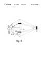
- FIG. 5provides a schematic diagram of an embodiment of an optical probe showing the presence of two turning mirrors.
- FIG. 6provides a functional block diagram of a system for examining a sample according to the present invention.
- FIG. 1shows a schematic cross-section of one embodiment of the optical probe 10 according the invention.
- a housing 14 having a proximal and a distal endis shown in this figure as enclosing the optical components. The distal end of the housing may be most remote from the operator or closest to the target sample. While a housing 14 is shown in the embodiment depicted in FIG. 1, it is understood that an optical probe may be constructed according to these systems and methods wherein the optical elements are not enclosed as a single housing. Other arrangements combining elements for illuminating a sample and for collecting light from the sample after its illumination may be readily envisioned by practitioners of ordinary skill in these arts, and certain of these arrangements are depicted in the embodiments illustrated in the following figures.
- FIG. 1further shows refractive optics 15 internal to the probe forming a focus 16 of the illuminating light on the surface of the sample 18 .
- the source of the illuminating light 12may be the end of a fiber of diameter d and numerical aperture Naf.
- the diameter of the optical elements and the placement of these elements relative to the end of the fiberare such that the light exiting the fiber is entirely collected by the optical elements and directed to a focal point of diameter D on the surface of the sample.
- the measure of Dmay be greater than, less than, or equal to the measure of d.
- the magnification of the illuminating opticsis then said to be D/d.
- Other configurations of illumination systemsmay be envisioned by or familiar to ordinarily skilled practitioners of these arts.
- optical system for the illumination and receiving sections of the probeare each drawn, for illustrative purposes, as comprising a single lens. It is understood that embodiments of the probe may be constructed that bear collections or arrays of lenses configured for different purposes, and that these additional embodiments are specifically contemplated by the systems and methods of the present invention.
- FIG. 1illustrates a single beam of illuminating light
- a plurality of optical fibers providing illuminating lightmay be illuminated in a sequential manner to create a pattern of illuminating light directed to the target.
- the order in which the fibers are illuminatedmay be predetermined in order to form a particularly advantageous pattern of illumination on the target.
- a scanning systemmay be included in these systems and methods to direct the sequence of fiber illumination. Patterns of illumination and sequencing of optical fibers to attain those patterns may be readily envisioned by those of ordinary skill in the relevant arts.
- the receiver optics 20is shown to be shaped in an annular fashion around the central illuminating optical path. While an annulus is depicted here, practitioners of ordinary skill in the art will appreciate that any geometric shape arranging the receiver optics circumferentially around a central illuminating axis may be substituted as embodiments falling within the scope of the present invention.
- the optic axis for the receiver opticsis the same as the optic axis for the illuminating optics.
- a baffle or barrier 24may optically separate the illuminating section of the optics from the receiving section. This barrier may prevent stray light from entering the receiver optics 20 directly from the illuminating portion of the probe.
- the component of the illuminating light that is specularly reflected (i.e., wherein the angle of reflection equals the angle of incidence) from the surface of the sample 18is not directed into the receiver section when the distal surface of the probe is normal to the line of sight (or symmetry axis) of the probe.
- This specular component of the reflectionmay be collected by the illuminating optics, rather than the receiver optics. As a result, the specular component may not be detected by the detector. Diffusely reflected light from the surface, however, can occur at angles other than the angle of incidence. Thus, a portion of this diffusely reflected light may be collected by the annular optical receiver optics and brought to a focus within the body of the probe
- spectroscopic methodssuch as fluorescence and Raman spectroscopy benefit from the fact that the specularly reflected component of the excitation beam is not collected by the receiver optics 20 .
- a lasermay be used to illuminate the sample at a specific wavelength.
- the light emitted from the sample as a result of the excitation by the laser beammay be produced by physical or chemical components of the sample.
- emitted lightmay be observed at wavelengths longer than the wavelength of the excitation beam, but shorter wavelengths can also be investigated.
- the specularly reflected laser beamtends to be more intense than the fluorescence signal, and may constitute unwanted radiation in fluorescence experiments.
- An embodiment of a probe as illustrated in FIG. 1may significantly reduce the amount of specularly reflected laser light entering the receiver portion, thus reducing the unwanted signal generated by the laser.
- fluorescence emitted by an illuminated sampledoes not retain the degree of collimation and wavelength purity of the illuminating laser beam. In most cases, fluorescence can be considered to be nearly isotropic, that is, that all directions for the fluorescence emission are equally probable. Therefore, fluorescence from a sample may be similar to diffuse reflectance, with light propagating into all possible angles from the surface. Also, the intensity of the fluorescence emitted from most samples can be very weak compared to the illuminating beam.
- the receiver section of the probemay thus be advantageously designed to collect a maximum amount of the emitted light from the sample in fluorescence applications. This may be accomplished by making the annular receiver area as large as possible, and by selecting optical coatings for the components that match the optical bandwidth of the fluorescence signal.
- FIG. 2depicts an embodiment wherein the illuminating laser beam is sufficiently well collimated that precise illuminating optics may become optional.
- a laser beam 30passes straight through the probe without alteration by an optical system.
- the illuminating portion of the probeoccupies the area between the two optical barriers 24 that separate the illuminating portion from the receiver optics 20 .
- Use of a well collimated laserreduces the area occupied by the illuminating portion of the probe, creating a greater overall area for the receiver optics 20 .
- An embodiment like that shown in FIG. 2is particularly well adapted for fluorescence studies of samples.
- Information concerning the physical, chemical, or biological nature of a samplecan be communicated through the diffusely reflected portion of the reflected light from the surface. This is especially true of biological tissue, where a portion of the illuminating light enters the tissue and undergoes scattering and absorption before exiting the tissue. Through this process, the propagation direction of the light is randomized, becoming diffusely reflected rather than specularly reflected.
- information regarding the sampleis imparted to the light beam, especially through the spectrum of the diffusely reflected beam. Diffuse reflectance from other samples such as soils, chemical powders, polymer surfaces, textiles, etc. contains information on the chemical composition of the sample.
- the optical probeit may be advantageous to balance the amount of light delivered to the sample and the amount of light collected by the receiver portion. This balancing may be desirable, for example, when a broadband white light is used to interrogate the sample by creating a diffused reflectance spectrum of the sample.
- a useful designmay provide an area of the illumination optics and an area of the receiving optics that are equal. For example, if the overall probe diameter is P, the diameter of the inner portion (the illuminating section in this embodiment) will be P/2 to achieve the equal areas in the receiver and illumination sections. An embodiment showing these features is illustrated in FIG. 3 .
- FIG. 3depicts an embodiment wherein the light collected by the receiver portion of the probe may be brought to a focus 38 at some distance from the collecting optics.
- the location of this focus 38is within the body of the probe.
- the focal length of the receiving optics 20may be longer than the focal length of the illumination optics. This will cause the location of the receiver focal spot 38 to fall at a greater distance from the optical system than the distance of the source from the same optical system. The result is the ability of the received light to pass around the location of the source and form a focal spot.
- This focal spot 38may advantageously coincide with the location of a detecting element.
- the focal spot 38may coincide with the location of a fiber end or a fiber bundle end adapted for transmitting received light to another location for detection. Similarly, it could be the location of a fiber end or fiber bundle end designed to transmit the received light to another location for detection. It is understood that any type of optical transducer, photodetector or phototransistor may be suitable for positioning at or near the focal spot to collect, measure or generate a signal in response to the focused light.
- the receiver optical element or elementsare arranged in a circumferential array around the illuminating beam in the depicted embodiment, the central portion of the conical beam coming to a focus, 38 , is obscured. This may allow the received beam to pass around the illuminating source 12 without losses.
- FIG. 4depicts an alternative embodiment not comprising the use of unequal focusing dimensions.
- a small turning mirror 50can be inserted into the illuminating beam path before the focusing lens 15 is encountered by the beam. This mirror 50 allows the illuminating source 12 to be placed away from 30 the point at which the received light is brought to a focus 38 by the receiving lenses 24 .
- FIG. 5depicts an embodiment wherein the operation of the optical probe 10 may advantageously employ an angular design instead of a straight design.
- a mirror 50can be used to deflect the illuminating light from illuminating source 12
- a mirror 55can be used to deflect the received light and direct it to a focus 38 .
- FIG. 6shows a functional block diagram of an embodiment of a system according to the present invention.
- This figureshows an optical probe 100 directed towards a sample 102 .
- a distance xexists between the distal end of the probe 100 and the sample 102 .
- the optical probe 100may contain all of the components necessary to generate the desired illuminating light and to convert the received light from the sample into electrical signals. Such a probe may be termed self-contained.
- the optical probe 100may receive transmitted light from a console 108 to which it is operably connected, or may transmit light received within the optical probe 100 to the console 108 . Such a probe may be termed remote-operated.
- the generation of the illuminating lightcan take place in the console 108 .
- This lightis carried to the optical probe 100 through the fibers within the connecting circuit 104 , where it is then formed by the optics in the probe 100 to come to a focus on the sample 102 .
- the collected light from the sample 102can be focused on the end of a fiber or bundle of fibers and transmitted to the console 108 for detection. If the connection to the console 108 is through electrical wires only, the generation of the illuminating light and the detection of the light emitted by the sample 102 must be done in the probe 100 .
- a remote-operated probemay be directed in three dimensional space via signals transmitted from an operator who directs the positioning of the optical probe 100 with respect to the sample 102 by inputting data into the console 108 .
- the optical probe 100is operably connected to the console 108 by a connecting circuit 104 , a conduit that may bear optical fibers, electrical wires or other conductors adapted for transmitting electromechanical energy.
- the connecting circuit 104may in some embodiments include systems for radiofrequency transmission.
- the connecting circuit 104provides a connection between the console 108 and the optical probe 100 , so that an operator may direct the functioning of the probe during the illumination of the sample 102 and during the collection of light emitted by the sample 102 .
- a probecould be directed, for example, to examine samples in locations inaccessible to human investigators.
- a probecould be affixed to a catheter system for use within a body lumen or a channel bearing body fluids.
- a probecould also be adapted for insertion into small orifices such as Eustachian tubes or nasopharyngeal or sinus passages.
- a probecould also be adapted for geological or industrial purposes, to be placed in small crevices or within structures.
- a probecould be adapted for use in hostile environments, including areas contaminated with infectious agents, toxins or radiation, and including inhospitable macroenvironments such as undersea use or extraterrestrial use.
- Other embodiments of an optical probe according to these systems and methodsmay be devised that are suitable for various other environments and applications, as will be envisioned by skilled practitioners in the relevant arts.
- Optical instruments used to interrogate the physical, chemical, or biological state of a samplemay involve a method for delivering specific, known qualities of light to the sample, and collecting the response light from the sample for detection and analysis.
- an optical probe 100may be incorporated in a system for delivering the required light to the sample 102 , and for collecting the resulting response for analysis.
- the optical probe 100may be designed to be hand-held. It may furthermore be designed to withstand extremes in environmental conditions such as temperature or pressure. It may contain all of the required components necessary to make the optical measurement of the sample, or it may be connected to a console unit in which the requisite measurement components are housed.
- the connecting circuit 104may comprise electrical, optical or other electromechanical components.
- Data related to light emitted from the sample 102may be manipulated within a processor 110 so that other data sets related to the emitted light may be obtained. Data may further be displayed in a graphical format on an image generator 114 .
- the optical probe 100may, in certain embodiments, bear a videocamera adapted for transmitting signals to a video system 112 .
- the video system 112may be configured to produce digital data related to the images of the sample 102 transmitted from the optical probe 100 . These digital data may be transmitted to the image generator 114 to be displayed graphically, or to be combined with other graphic representations to produce a composite graphical image.
- the optical probe 100may be brought into proximity to the sample 102 .
- Proper operating distance x from the samplemay advantageously be established in a number of ways.
- the distance x from the sample 102 to the optical probe 100can be measured, or can be fixed using a rod of known length. If this is not possible, however, other methods for determining the proper operating distance can be used.
- an optical method for distance controlmay be used wherein a visible grid or array of multiple spots on the sample may be generated from an auxiliary light source in the console or in the probe.
- the gridmay be projected through the optics in the probe onto the target. When the grid is in focus, the probe 100 is understood to be at the correct distance x from the sample 102 .
- Proper focus of the confocal devicemay be judged by the quality of the focus presented in the video image, or it may be augmented by specific focusing aids.
- An example of a focusing aidcomprises a projected grid or series of spots on the target. In this example, gross motion of the probe towards or away from the target will bring the grid or spots into sharp focus, as viewed through the video channel. Fine adjustment of the focus can be made as in a camera, by the adjustment of the optical system delivering and receiving the light.
- an array of visible spotsmay be generated on the sample 102 by illuminating fibers in a fiber bundle located in the probe 100 , using, for example, a small laser situated in the console or in the probe.
- the pattern of fibers in the bundlemay be brought to a focus on the target sample 102 by the optics in the optical probe 100 .
- the probe 100is in the proper position relative to the sample 102 .
- angular errorssuch as tilt of the probe can be eliminated when the correct focus is set for each of the spots.
- a video viewing capabilitymay be useful to confirm proper focus of the sample and proper alignment of the probe to the sample.
- a video viewing capabilitymay be advantageously employed when the optical probe is used in confining spaces, or where access to the probe during operation is difficult or impossible.
- the video cameramay furthermore permit the operator to position the probe for proper focus in relation to the sample. Viewing the focusing grid or spots may be accomplished through the optical configuration of the probe 100 , allowing an operator to confirm the accuracy of the focus of the probe's optics upon the sample. This feature may be provided by means of a video camera mounted in the probe 100 .
- a beam splitter(not shown) may be provided in the transmitting beam path to combine a video capability with the diagnostic capability of the probe.
- the beam splitting elementmay align the viewing direction with the direction of the illuminating beam being transmitted to the sample.
- the generation of the focusing grid or spotsmay take place in the receiver section of the device. That is, the receiver optics may be used to project the focusing grid or spot array onto the sample.
- the receiver portion of the probemay be used to create the illumination of the focusing spots.
- a measure of the receiver focusmay be provided along with the visual realization of the illuminating focus offered by the video camera.
- the location of the probe for optimum focus of both the transmitting and receiving portions of the probemay be determined.
- the probe 100is suitable for examination of a sample 102 that includes a body tissue.
- a body tissuemay include an in vivo or an ex vivo tissue sample.
- a body tissuemay include any tissue of a living body, whether external or internal.
- Body tissuesmay be accessed via endoscopes, probes, specula, open surgical techniques or any other method familiar to practitioners in the relevant arts.
- Other approaches to body tissues suitable for the present inventionwill be apparent to those of ordinary skill in the medical arts.
- the examination of a body tissuemay yield a diagnosis of a medical condition.
- a medical conditionmay comprise any physiological or pathological state of relevance to the health or well-being of a human subject. Medical conditions include both normal and abnormal conditions, and further include an entire spectrum of abnormalities.
- Examples of medical conditionsinclude neoplasms, malignancies, dysplasias, inflammation, infection, endocrine disorders, metabolic disorders, vascular abnormalities, reparative processes, regenerative processes, degenerative processes and other conditions affecting the health or well-being of the subject.
- Data related to the systems and methods of the present inventionmay be processed to yield information about medical conditions and diagnoses.
- data collected from the examination of a body tissue of a patientmay be compared to known data profiles for known medical conditions or diagnoses, so that a diagnosis may be established for the patient.
- normal and abnormal levelsmay be established for certain data points or data sets, so that the presence or absence of disease may be established by comparing the data points or data sets obtained from the examination of a patient's body tissue with the established parameters.
- the present inventionfurther provides for the establishment of a treatment plan based thereupon. The diagnosed medical condition may then be treated according to the treatment plan.
- data related to the examination of the patientmay be correlated with other data in the patient's medical record.
- the systems and methods of the present inventionmay collect data pertaining to the examination procedure itself.
- the system according to the present inventionmay measure and record information about the duration of the procedure, the amount of energy or other consumable supplies utilized to perform the procedure, the number of measurements taken during the procedure, or any other features of the procedure of significance.
- the procedure and its durationmay be tallied and correlated with patient information so that an appropriate bill for the service may be constructed.
- Billing informationmay be entered into a database that can then be accessed by the system to produce a bill for the particular procedure.
- the billing informationmay include a diagnostic or a procedural code for categorizing the procedure so that a bill bearing this information may be generated that will then be associated with a schedule of predetermined fees.
- Diagnosis according to ICD-9 codes and procedural terminology according to CPT codesare well-known in the art.
- Other codes or categoriesmay be used for organizing a patients billing information, so that each procedure according to these systems and methods will generate an accurate bill.
- Billing informationmay differ from one patient to the next according to the fee schedules for various managed care organizations and third-party payors.
- the systems and methods of the present informationmay comprise the entry of billing information for a particular patient into a database. The billing information may then be correlated with data about the procedure itself or with data about the diagnosis produced in order to generate an accurate bill.
Landscapes
- Health & Medical Sciences (AREA)
- Life Sciences & Earth Sciences (AREA)
- Medical Informatics (AREA)
- Biophysics (AREA)
- Pathology (AREA)
- Engineering & Computer Science (AREA)
- Biomedical Technology (AREA)
- Heart & Thoracic Surgery (AREA)
- Physics & Mathematics (AREA)
- Molecular Biology (AREA)
- Surgery (AREA)
- Animal Behavior & Ethology (AREA)
- General Health & Medical Sciences (AREA)
- Public Health (AREA)
- Veterinary Medicine (AREA)
- Nuclear Medicine, Radiotherapy & Molecular Imaging (AREA)
- Radiology & Medical Imaging (AREA)
- Investigating Or Analysing Materials By Optical Means (AREA)
- Investigating, Analyzing Materials By Fluorescence Or Luminescence (AREA)
Abstract
Description
Claims (32)
Priority Applications (6)
| Application Number | Priority Date | Filing Date | Title |
|---|---|---|---|
| US09/470,071US6411838B1 (en) | 1998-12-23 | 1999-12-22 | Systems and methods for optical examination of samples |
| US09/738,613US6385484B2 (en) | 1998-12-23 | 2000-12-15 | Spectroscopic system employing a plurality of data types |
| US09/738,481US6421553B1 (en) | 1998-12-23 | 2000-12-15 | Spectral data classification of samples |
| US10/071,932US20020133073A1 (en) | 1998-12-23 | 2002-02-08 | Spectroscopic system employing a plurality of data types |
| US10/178,772US6760613B2 (en) | 1998-12-23 | 2002-06-24 | Substantially monostatic, substantially confocal optical systems for examination of samples |
| US10/870,672US20050033186A1 (en) | 1998-12-23 | 2004-06-17 | Substantially monostatic, substantially confocal optical systems for examination of samples |
Applications Claiming Priority (2)
| Application Number | Priority Date | Filing Date | Title |
|---|---|---|---|
| US11376198P | 1998-12-23 | 1998-12-23 | |
| US09/470,071US6411838B1 (en) | 1998-12-23 | 1999-12-22 | Systems and methods for optical examination of samples |
Related Child Applications (3)
| Application Number | Title | Priority Date | Filing Date |
|---|---|---|---|
| US09/738,613Continuation-In-PartUS6385484B2 (en) | 1998-12-23 | 2000-12-15 | Spectroscopic system employing a plurality of data types |
| US09/738,481Continuation-In-PartUS6421553B1 (en) | 1998-12-23 | 2000-12-15 | Spectral data classification of samples |
| US10/178,772ContinuationUS6760613B2 (en) | 1998-12-23 | 2002-06-24 | Substantially monostatic, substantially confocal optical systems for examination of samples |
Publications (1)
| Publication Number | Publication Date |
|---|---|
| US6411838B1true US6411838B1 (en) | 2002-06-25 |
Family
ID=22351348
Family Applications (6)
| Application Number | Title | Priority Date | Filing Date |
|---|---|---|---|
| US09/470,071Expired - LifetimeUS6411838B1 (en) | 1998-12-23 | 1999-12-22 | Systems and methods for optical examination of samples |
| US09/738,481Expired - LifetimeUS6421553B1 (en) | 1998-12-23 | 2000-12-15 | Spectral data classification of samples |
| US09/738,613Expired - LifetimeUS6385484B2 (en) | 1998-12-23 | 2000-12-15 | Spectroscopic system employing a plurality of data types |
| US10/071,932AbandonedUS20020133073A1 (en) | 1998-12-23 | 2002-02-08 | Spectroscopic system employing a plurality of data types |
| US10/178,772Expired - Fee RelatedUS6760613B2 (en) | 1998-12-23 | 2002-06-24 | Substantially monostatic, substantially confocal optical systems for examination of samples |
| US10/870,672AbandonedUS20050033186A1 (en) | 1998-12-23 | 2004-06-17 | Substantially monostatic, substantially confocal optical systems for examination of samples |
Family Applications After (5)
| Application Number | Title | Priority Date | Filing Date |
|---|---|---|---|
| US09/738,481Expired - LifetimeUS6421553B1 (en) | 1998-12-23 | 2000-12-15 | Spectral data classification of samples |
| US09/738,613Expired - LifetimeUS6385484B2 (en) | 1998-12-23 | 2000-12-15 | Spectroscopic system employing a plurality of data types |
| US10/071,932AbandonedUS20020133073A1 (en) | 1998-12-23 | 2002-02-08 | Spectroscopic system employing a plurality of data types |
| US10/178,772Expired - Fee RelatedUS6760613B2 (en) | 1998-12-23 | 2002-06-24 | Substantially monostatic, substantially confocal optical systems for examination of samples |
| US10/870,672AbandonedUS20050033186A1 (en) | 1998-12-23 | 2004-06-17 | Substantially monostatic, substantially confocal optical systems for examination of samples |
Country Status (6)
| Country | Link |
|---|---|
| US (6) | US6411838B1 (en) |
| EP (1) | EP1161178A2 (en) |
| JP (1) | JP2002533142A (en) |
| AU (1) | AU759282B2 (en) |
| CA (1) | CA2356623C (en) |
| WO (1) | WO2000037917A2 (en) |
Cited By (92)
| Publication number | Priority date | Publication date | Assignee | Title |
|---|---|---|---|---|
| US20020107668A1 (en)* | 2000-12-15 | 2002-08-08 | Costa Peter J. | System for normalizing spectra |
| US20020121443A1 (en)* | 2000-11-13 | 2002-09-05 | Genoptix | Methods for the combined electrical and optical identification, characterization and/or sorting of particles |
| US20020123112A1 (en)* | 2000-11-13 | 2002-09-05 | Genoptix | Methods for increasing detection sensitivity in optical dielectric sorting systems |
| US20020160470A1 (en)* | 2000-11-13 | 2002-10-31 | Genoptix | Methods and apparatus for generating and utilizing linear moving optical gradients |
| US20030007894A1 (en)* | 2001-04-27 | 2003-01-09 | Genoptix | Methods and apparatus for use of optical forces for identification, characterization and/or sorting of particles |
| US20030124516A1 (en)* | 2001-04-27 | 2003-07-03 | Genoptix, Inc. | Method of using optical interrogation to determine a biological property of a cell or population of cells |
| US20030194755A1 (en)* | 2001-04-27 | 2003-10-16 | Genoptix, Inc. | Early detection of apoptotic events and apoptosis using optophoretic analysis |
| WO2003093496A1 (en)* | 2002-05-01 | 2003-11-13 | Genoptix, Inc. | Method of using optical interrogation to determine a biological property of a cell or population of cells |
| US20030211461A1 (en)* | 2002-05-01 | 2003-11-13 | Genoptix, Inc | Optophoretic detection of durgs exhibiting inhibitory effect on Bcr-Abl positive tumor cells |
| US20040007674A1 (en)* | 2002-07-09 | 2004-01-15 | Schomacker Kevin T. | Method and apparatus for identifying spectral artifacts |
| US20040009540A1 (en)* | 2001-04-27 | 2004-01-15 | Genoptix, Inc | Detection and evaluation of cancer cells using optophoretic analysis |
| US20040023310A1 (en)* | 2001-04-27 | 2004-02-05 | Genoptix, Inc | Quantitative determination of protein kinase C activation using optophoretic analysis |
| US20040097790A1 (en)* | 2000-06-30 | 2004-05-20 | Inner Vision Imaging, L.L.C. | Endoscope |
| US20040121307A1 (en)* | 2002-12-19 | 2004-06-24 | Genoptix, Inc | Early detection of cellular differentiation using optophoresis |
| US20040121474A1 (en)* | 2002-12-19 | 2004-06-24 | Genoptix, Inc | Detection and evaluation of chemically-mediated and ligand-mediated t-cell activation using optophoretic analysis |
| US6760613B2 (en) | 1998-12-23 | 2004-07-06 | Medispectra, Inc. | Substantially monostatic, substantially confocal optical systems for examination of samples |
| US6768918B2 (en) | 2002-07-10 | 2004-07-27 | Medispectra, Inc. | Fluorescent fiberoptic probe for tissue health discrimination and method of use thereof |
| US20040230132A1 (en)* | 2003-02-07 | 2004-11-18 | Alfred E. Mann Institute For Biomedical Engineering At The | Surgical drain with positioning and protective features |
| US6826422B1 (en) | 1997-01-13 | 2004-11-30 | Medispectra, Inc. | Spectral volume microprobe arrays |
| US6847490B1 (en) | 1997-01-13 | 2005-01-25 | Medispectra, Inc. | Optical probe accessory device for use in vivo diagnostic procedures |
| US20050020892A1 (en)* | 1999-10-08 | 2005-01-27 | George Acosta | Compact apparatus for noninvasive measurement of glucose through near-infrared spectroscopy |
| US20050054908A1 (en)* | 2003-03-07 | 2005-03-10 | Blank Thomas B. | Photostimulation method and apparatus in combination with glucose determination |
| US20050090750A1 (en)* | 2002-04-04 | 2005-04-28 | Ediger Marwood N. | Determination of disease state using Raman Spectroscopy of tissue |
| US20050094232A1 (en)* | 2000-11-13 | 2005-05-05 | Genoptix, Inc. | System and method for separating micro-particles |
| US20050159656A1 (en)* | 2003-03-07 | 2005-07-21 | Hockersmith Linda J. | Method and apparatus for presentation of noninvasive glucose concentration information |
| US6933154B2 (en) | 2002-07-09 | 2005-08-23 | Medispectra, Inc. | Optimal windows for obtaining optical data for characterization of tissue samples |
| US20050187439A1 (en)* | 2003-03-07 | 2005-08-25 | Blank Thomas B. | Sampling interface system for in-vivo estimation of tissue analyte concentration |
| US20050203359A1 (en)* | 2000-05-02 | 2005-09-15 | Blank Thomas B. | Optical sampling interface system for in-vivo measurement of tissue |
| US20050207940A1 (en)* | 2003-08-28 | 2005-09-22 | Butler William F | Methods and apparatus for sorting cells using an optical switch in a microfluidic channel network |
| US20050215876A1 (en)* | 2004-03-25 | 2005-09-29 | Eastman Kodak Company | Method and system for automatic image adjustment for in vivo image diagnosis |
| US20050267342A1 (en)* | 2004-04-28 | 2005-12-01 | Blank Thomas B | Noninvasive analyzer sample probe interface method and apparatus |
| US20060072874A1 (en)* | 2004-10-01 | 2006-04-06 | University Of Washington | Configuration memory for a scanning beam device |
| US20060072843A1 (en)* | 2004-10-01 | 2006-04-06 | University Of Washington | Remapping methods to reduce distortions in images |
| US20060109757A1 (en)* | 2004-11-19 | 2006-05-25 | Canon Kabushiki Kaisha | Automatic focusing apparatus, laser processing apparatus, and laser cutting apparatus |
| WO2006056965A1 (en) | 2004-11-26 | 2006-06-01 | L'oreal | A method of observing biological tissue, in particular human skin |
| US20060116562A1 (en)* | 2002-03-08 | 2006-06-01 | Acosta George M | Compact apparatus for noninvasive measurement of glucose through near-infrared spectroscopy |
| US20060138238A1 (en)* | 2004-12-23 | 2006-06-29 | University Of Washington | Methods of driving a scanning beam device to achieve high frame rates |
| US20060186325A1 (en)* | 2005-02-23 | 2006-08-24 | University Of Washington | Scanning beam device with detector assembly |
| US7103401B2 (en) | 2002-07-10 | 2006-09-05 | Medispectra, Inc. | Colonic polyp discrimination by tissue fluorescence and fiberoptic probe |
| US20060200017A1 (en)* | 2002-03-08 | 2006-09-07 | Monfre Stephen L | Noninvasive targeting system method and apparatus |
| US20060206018A1 (en)* | 2005-03-04 | 2006-09-14 | Alan Abul-Haj | Method and apparatus for noninvasive targeting |
| US20060211931A1 (en)* | 2000-05-02 | 2006-09-21 | Blank Thomas B | Noninvasive analyzer sample probe interface method and apparatus |
| US20060226231A1 (en)* | 2005-03-29 | 2006-10-12 | University Of Washington | Methods and systems for creating sequential color images |
| US7127282B2 (en) | 1998-12-23 | 2006-10-24 | Medispectra, Inc. | Optical methods and systems for rapid screening of the cervix |
| US7136518B2 (en) | 2003-04-18 | 2006-11-14 | Medispectra, Inc. | Methods and apparatus for displaying diagnostic data |
| US20070019906A1 (en)* | 2005-07-21 | 2007-01-25 | University Of Washington Uw Tech Transfer - Invention Licensing | Methods and systems for counterbalancing a scanning beam device |
| US7183759B1 (en)* | 2003-04-07 | 2007-02-27 | Luxtera, Inc. | Optical probes with spacing sensors for the wafer level testing of optical and optoelectronic chips |
| US7187810B2 (en) | 1999-12-15 | 2007-03-06 | Medispectra, Inc. | Methods and systems for correcting image misalignment |
| US20070081168A1 (en)* | 2005-08-23 | 2007-04-12 | University Of Washington - Uw Techtransfer | Distance determination in a scanned beam image capture device |
| US20070149868A1 (en)* | 2002-03-08 | 2007-06-28 | Blank Thomas B | Method and Apparatus for Photostimulation Enhanced Analyte Property Estimation |
| US20070161876A1 (en)* | 2005-11-18 | 2007-07-12 | Spectrx, Inc. | Method and apparatus for rapid detection and diagnosis of tissue abnormalities |
| US7260248B2 (en) | 1999-12-15 | 2007-08-21 | Medispectra, Inc. | Image processing using measures of similarity |
| US20070219450A1 (en)* | 2004-12-22 | 2007-09-20 | Azar Fred S | Three-dimensional breast anatomy imaging system |
| US20070234300A1 (en)* | 2003-09-18 | 2007-10-04 | Leake David W | Method and Apparatus for Performing State-Table Driven Regression Testing |
| US7282723B2 (en) | 2002-07-09 | 2007-10-16 | Medispectra, Inc. | Methods and apparatus for processing spectral data for use in tissue characterization |
| US7309867B2 (en) | 2003-04-18 | 2007-12-18 | Medispectra, Inc. | Methods and apparatus for characterization of tissue samples |
| US20080033275A1 (en)* | 2004-04-28 | 2008-02-07 | Blank Thomas B | Method and Apparatus for Sample Probe Movement Control |
| US20080073517A1 (en)* | 2006-09-13 | 2008-03-27 | Charles David Melville | Temperature adjustment in scanning beam devices |
| US7389137B2 (en)* | 2002-07-25 | 2008-06-17 | Biophan Technologies, Inc. | Optical MRI catheter system |
| US20080144998A1 (en)* | 2006-12-15 | 2008-06-19 | University Of Washington | Attaching optical fibers to actuator tubes with beads acting as spacers and adhesives |
| US20080165360A1 (en)* | 2007-01-10 | 2008-07-10 | University Of Washington | Scanning beam device calibration |
| US20080186496A1 (en)* | 2004-11-26 | 2008-08-07 | L'oreal | Method of Observing Biological Tissue, in Particular Human Skin |
| US20080218735A1 (en)* | 2004-01-09 | 2008-09-11 | Hamamatsu Photonics K.K. | Laser Processing Method And Device |
| US20080249369A1 (en)* | 2007-04-05 | 2008-10-09 | University Of Washington | Compact scanning fiber device |
| US20080251506A1 (en)* | 2004-01-09 | 2008-10-16 | Kazuhiro Atsumi | Laser Processing Method and Device |
| US20080265178A1 (en)* | 2007-04-26 | 2008-10-30 | University Of Washington | Driving scanning fiber devices with variable frequency drive signals |
| US20080281207A1 (en)* | 2007-05-08 | 2008-11-13 | University Of Washington | Image acquisition through filtering in multiple endoscope systems |
| US20080281159A1 (en)* | 2007-05-08 | 2008-11-13 | University Of Washington | Coordinating image acquisition among multiple endoscopes |
| US20080291597A1 (en)* | 2007-05-22 | 2008-11-27 | Seibel Eric J | Scanning beam device having different image acquisition modes |
| US7459696B2 (en) | 2003-04-18 | 2008-12-02 | Schomacker Kevin T | Methods and apparatus for calibrating spectral data |
| US7469160B2 (en) | 2003-04-18 | 2008-12-23 | Banks Perry S | Methods and apparatus for evaluating image focus |
| US20080319382A1 (en)* | 2002-03-08 | 2008-12-25 | Blank Thomas B | Method and apparatus for coupling a channeled sample probe to tissue |
| US20080319299A1 (en)* | 2004-04-28 | 2008-12-25 | Stippick Timothy W | Method and apparatus for controlling positioning of a noninvasive analyzer sample probe |
| US20090026888A1 (en)* | 2007-07-25 | 2009-01-29 | University Of Washington | Actuating an optical fiber with a piezoelectric actuator and detecting voltages generated by the piezoelectric actuator |
| US20090036759A1 (en)* | 2007-08-01 | 2009-02-05 | Ault Timothy E | Collapsible noninvasive analyzer method and apparatus |
| US20090092364A1 (en)* | 2007-10-04 | 2009-04-09 | University Of Washington | Reducing distortion in scanning fiber devices |
| US20090103882A1 (en)* | 2006-12-15 | 2009-04-23 | Charles David Melville | Attaching optical fibers to actuator tubes with beads acting as spacers and adhesives |
| US20090141997A1 (en)* | 2007-11-30 | 2009-06-04 | University Of Washington | Reducing noise in images acquired with a scanning beam device |
| US20090247840A1 (en)* | 2002-03-08 | 2009-10-01 | Sensys Medical, Inc. | Method and apparatus for coupling a sample probe with a sample site |
| US20090259446A1 (en)* | 2008-04-10 | 2009-10-15 | Schlumberger Technology Corporation | Method to generate numerical pseudocores using borehole images, digital rock samples, and multi-point statistics |
| US20100097692A1 (en)* | 2008-10-22 | 2010-04-22 | Microbrightfield, Inc. | Movable Objective Lens Assembly for an Optical Microscope and Optical Microscopes Having Such an Assembly |
| US7784697B2 (en) | 2004-12-23 | 2010-08-31 | University Of Washington | Methods of driving a scanning beam device to achieve high frame rates |
| US20110004448A1 (en)* | 2009-07-01 | 2011-01-06 | Schlumberger Technology Corporation | Method to quantify discrete pore shapes, volumes, and surface areas using confocal profilometry |
| US20110004447A1 (en)* | 2009-07-01 | 2011-01-06 | Schlumberger Technology Corporation | Method to build 3D digital models of porous media using transmitted laser scanning confocal mircoscopy and multi-point statistics |
| US7884933B1 (en) | 2010-05-05 | 2011-02-08 | Revolutionary Business Concepts, Inc. | Apparatus and method for determining analyte concentrations |
| US20120179010A1 (en)* | 2002-04-04 | 2012-07-12 | Maynard John D | Determination of a Measure of a Glycation End-Product or Disease State Using Tissue Fluorescence of Various Sites |
| US20140145083A1 (en)* | 2012-11-28 | 2014-05-29 | Shimadzu Corporation | Plastic identification device |
| WO2014121389A1 (en)* | 2013-02-05 | 2014-08-14 | Rafal Pawluczyk | Fibre optic probe for remote spectroscopy |
| US8993922B2 (en) | 2004-01-09 | 2015-03-31 | Hamamatsu Photonics K.K. | Laser processing method and device |
| US9433468B2 (en) | 2013-10-04 | 2016-09-06 | Tidi Products, Llc | Sheath for a medical or dental instrument |
| US20160313211A1 (en)* | 2013-12-16 | 2016-10-27 | Nippon Telegraph And Telephone Corporation | End face observation device |
| US9581723B2 (en) | 2008-04-10 | 2017-02-28 | Schlumberger Technology Corporation | Method for characterizing a geological formation traversed by a borehole |
Families Citing this family (111)
| Publication number | Priority date | Publication date | Assignee | Title |
|---|---|---|---|---|
| US20010041843A1 (en)* | 1999-02-02 | 2001-11-15 | Mark Modell | Spectral volume microprobe arrays |
| JP2000275757A (en)* | 1999-03-24 | 2000-10-06 | Fuji Photo Film Co Ltd | Method and device for evaluating image |
| EP1178311A4 (en)* | 1999-05-10 | 2003-04-09 | Tomoya Sato | Method and apparatus for determining the type and/or condition of disease and method and apparatus for screening drug |
| US7280866B1 (en)* | 1999-10-06 | 2007-10-09 | National Research Council Of Canada | Non-invasive screening of skin diseases by visible/near-infrared spectroscopy |
| US6902935B2 (en)* | 1999-12-15 | 2005-06-07 | Medispectra, Inc. | Methods of monitoring effects of chemical agents on a sample |
| US20070021929A1 (en)* | 2000-01-07 | 2007-01-25 | Transform Pharmaceuticals, Inc. | Computing methods for control of high-throughput experimental processing, digital analysis, and re-arraying comparative samples in computer-designed arrays |
| US7108970B2 (en)* | 2000-01-07 | 2006-09-19 | Transform Pharmaceuticals, Inc. | Rapid identification of conditions, compounds, or compositions that inhibit, prevent, induce, modify, or reverse transitions of physical state |
| KR20020071931A (en)* | 2000-01-07 | 2002-09-13 | 트렌스폼 파마수티컬스 인코퍼레이티드 | High-throughput formation, identification, and analysis of diverse solid-forms |
| US20050089923A9 (en)* | 2000-01-07 | 2005-04-28 | Levinson Douglas A. | Method and system for planning, performing, and assessing high-throughput screening of multicomponent chemical compositions and solid forms of compounds |
| US20050118637A9 (en)* | 2000-01-07 | 2005-06-02 | Levinson Douglas A. | Method and system for planning, performing, and assessing high-throughput screening of multicomponent chemical compositions and solid forms of compounds |
| US20040252299A9 (en)* | 2000-01-07 | 2004-12-16 | Lemmo Anthony V. | Apparatus and method for high-throughput preparation and spectroscopic classification and characterization of compositions |
| US20050095696A9 (en)* | 2000-01-07 | 2005-05-05 | Lemmo Anthony V. | Apparatus and method for high-throughput preparation and characterization of compositions |
| US20070020662A1 (en)* | 2000-01-07 | 2007-01-25 | Transform Pharmaceuticals, Inc. | Computerized control of high-throughput experimental processing and digital analysis of comparative samples for a compound of interest |
| GB0008563D0 (en)* | 2000-04-07 | 2000-05-24 | Cambridge Discovery Chemistry | Investigating different physical and/or chemical forms of materials |
| WO2002007585A2 (en)* | 2000-07-13 | 2002-01-31 | Virginia Commonwealth University | Tissue interrogation spectroscopy |
| US6652464B2 (en) | 2000-12-18 | 2003-11-25 | Biosense, Inc. | Intracardiac pressure monitoring method |
| US6783499B2 (en)* | 2000-12-18 | 2004-08-31 | Biosense, Inc. | Anchoring mechanism for implantable telemetric medical sensor |
| US6636769B2 (en) | 2000-12-18 | 2003-10-21 | Biosense, Inc. | Telemetric medical system and method |
| US6638231B2 (en) | 2000-12-18 | 2003-10-28 | Biosense, Inc. | Implantable telemetric medical sensor and method |
| US20060129329A1 (en)* | 2001-04-09 | 2006-06-15 | Kobylecki Ryszard J | Investigating different physical and/or chemical forms of materials |
| US7831442B1 (en) | 2001-05-16 | 2010-11-09 | Perot Systems Corporation | System and method for minimizing edits for medical insurance claims processing |
| US7822621B1 (en) | 2001-05-16 | 2010-10-26 | Perot Systems Corporation | Method of and system for populating knowledge bases using rule based systems and object-oriented software |
| US7236940B2 (en) | 2001-05-16 | 2007-06-26 | Perot Systems Corporation | Method and system for assessing and planning business operations utilizing rule-based statistical modeling |
| US7808633B2 (en)* | 2007-02-14 | 2010-10-05 | Chemimage Corporation | Spectroscopic system and method for predicting outcome of disease |
| US7956996B2 (en)* | 2007-02-14 | 2011-06-07 | Chemimage Corporation | Distinguishing between invasive ductal carcinoma and invasive lobular carcinoma using raman molecular imaging |
| US7216088B1 (en) | 2001-07-26 | 2007-05-08 | Perot Systems Corporation | System and method for managing a project based on team member interdependency and impact relationships |
| US20030065477A1 (en)* | 2001-08-30 | 2003-04-03 | Opdyke John D. | Two-sample permutation tests |
| IL160702A0 (en)* | 2001-09-07 | 2004-08-31 | Transform Pharmaceuticals Inc | Apparatus and method for high-throughput preparation and characterization of composition |
| JP3944383B2 (en)* | 2001-11-16 | 2007-07-11 | 株式会社日立製作所 | Cardiac magnetic field measuring device |
| US7313531B2 (en) | 2001-11-29 | 2007-12-25 | Perot Systems Corporation | Method and system for quantitatively assessing project risk and effectiveness |
| FI113497B (en)* | 2002-02-28 | 2004-04-30 | Vaisala Oyj | lidar |
| US20040208385A1 (en)* | 2003-04-18 | 2004-10-21 | Medispectra, Inc. | Methods and apparatus for visually enhancing images |
| US7373198B2 (en)* | 2002-07-12 | 2008-05-13 | Bionova Technologies Inc. | Method and apparatus for the estimation of anesthetic depth using wavelet analysis of the electroencephalogram |
| US7060075B2 (en)* | 2002-07-18 | 2006-06-13 | Biosense, Inc. | Distal targeting of locking screws in intramedullary nails |
| US20040064053A1 (en)* | 2002-09-30 | 2004-04-01 | Chang Sung K. | Diagnostic fluorescence and reflectance |
| JP4041421B2 (en)* | 2003-03-25 | 2008-01-30 | 独立行政法人理化学研究所 | Raman probe and Raman scattering measuring apparatus using the same |
| JP2007524833A (en) | 2003-07-01 | 2007-08-30 | ザ リージェンツ オブ ザ ユニバーシティ オブ ミシガン | Method and apparatus for diagnosing bone tissue condition |
| US20050119587A1 (en)* | 2003-07-01 | 2005-06-02 | University Of Michigan | Method and apparatus for evaluating connective tissue conditions |
| USD500134S1 (en) | 2003-09-04 | 2004-12-21 | Medispectra, Inc. | Sheath for cervical optical probe |
| USD507349S1 (en) | 2003-09-04 | 2005-07-12 | Medispectra, Inc. | Sheath for cervical optical probe |
| US7970452B2 (en)* | 2003-09-30 | 2011-06-28 | Hologic, Inc. | Open architecture imaging apparatus and coil system for magnetic resonance imaging |
| US7379769B2 (en)* | 2003-09-30 | 2008-05-27 | Sunnybrook Health Sciences Center | Hybrid imaging method to monitor medical device delivery and patient support for use in the method |
| US20080077005A1 (en)* | 2004-08-12 | 2008-03-27 | Piron Cameron A | System and Method for Multimodality Breast Imaging |
| US7908690B2 (en)* | 2003-09-30 | 2011-03-22 | Sentinelle Medical, Inc. | Supine patient support for medical imaging |
| DE10355150B4 (en)* | 2003-11-26 | 2021-01-14 | Leica Microsystems Cms Gmbh | Method and system for the analysis of co-localizations |
| WO2005052558A1 (en)* | 2003-11-28 | 2005-06-09 | Bc Cancer Agency | Multimodal detection of tissue abnormalities based on raman and background fluorescence spectroscopy |
| US7697576B2 (en)* | 2004-05-05 | 2010-04-13 | Chem Image Corporation | Cytological analysis by raman spectroscopic imaging |
| US7316904B1 (en) | 2004-06-30 | 2008-01-08 | Chromodynamics, Inc. | Automated pap screening using optical detection of HPV with or without multispectral imaging |
| WO2006019991A2 (en)* | 2004-07-15 | 2006-02-23 | Cheminage Corporation | Method and apparatus for multimodal detection |
| US7254501B1 (en)* | 2004-12-10 | 2007-08-07 | Ahura Corporation | Spectrum searching method that uses non-chemical qualities of the measurement |
| US7854705B2 (en)* | 2004-12-16 | 2010-12-21 | Olga Pawluczyk | Ex vivo verification of biopsy tissue samples |
| US7524445B2 (en)* | 2004-12-31 | 2009-04-28 | Boston Scientific Scimed, Inc. | Method for making ePTFE and structure containing such ePTFE, such as a vascular graft |
| WO2006076772A1 (en)* | 2005-01-21 | 2006-07-27 | Optiscan Pty Ltd | Fibre bundle confocal endomicroscope |
| US7219038B2 (en)* | 2005-03-22 | 2007-05-15 | College Of William And Mary | Automatic peak identification method |
| US7627059B2 (en)* | 2005-04-05 | 2009-12-01 | Samsung Electronics Co., Ltd. | Method of robust timing detection and carrier frequency offset estimation for OFDM systems |
| US7616699B2 (en)* | 2005-04-12 | 2009-11-10 | Samsung Electronics Co., Ltd. | Method of soft bit metric calculation with direct matrix inversion MIMO detection |
| US8582089B2 (en)* | 2006-06-09 | 2013-11-12 | Chemimage Corporation | System and method for combined raman, SWIR and LIBS detection |
| US7679740B2 (en)* | 2005-07-14 | 2010-03-16 | Chemimage Corporation | Method and apparatus for multimodal detection |
| EP1902301A4 (en) | 2005-07-14 | 2010-09-22 | Chemimage Corp | Time and space resolved standoff hyperspectral ied explosives lidar detector |
| EP1938273A2 (en)* | 2005-08-26 | 2008-07-02 | Camtek Ltd. | Device and method for inspecting an object |
| US7729749B2 (en)* | 2005-09-01 | 2010-06-01 | The Regents Of The University Of Michigan | Method and apparatus for evaluating connective tissue conditions |
| WO2007056568A2 (en)* | 2005-11-09 | 2007-05-18 | Chemimage Corporation | Spectral imaging of biofilms |
| US20070178067A1 (en)* | 2005-11-09 | 2007-08-02 | John Maier | System and method for cytological analysis by raman spectroscopic imaging |
| US7751506B2 (en) | 2005-12-01 | 2010-07-06 | Samsung Electronics Co., Ltd. | Method for the soft bit metric calculation with linear MIMO detection for LDPC codes |
| WO2008002324A2 (en)* | 2005-12-23 | 2008-01-03 | Chemimage Corporation | Chemical imaging explosives (chimed) optical sensor |
| US8368880B2 (en)* | 2005-12-23 | 2013-02-05 | Chemimage Corporation | Chemical imaging explosives (CHIMED) optical sensor using SWIR |
| US8379197B2 (en)* | 2006-01-05 | 2013-02-19 | Chemimage Corporation | Spectroscopic systems and methods for classifying and pharmaceutically treating cells |
| US7570356B2 (en)* | 2006-01-05 | 2009-08-04 | Chemimage Corporation | System and method for classifying cells and the pharmaceutical treatment of such cells using Raman spectroscopy |
| WO2008016590A2 (en) | 2006-07-31 | 2008-02-07 | Visualant, Inc. | System and method of evaluating an object using electromagnetic energy |
| US8081304B2 (en) | 2006-07-31 | 2011-12-20 | Visualant, Inc. | Method, apparatus, and article to facilitate evaluation of objects using electromagnetic energy |
| US7996173B2 (en)* | 2006-07-31 | 2011-08-09 | Visualant, Inc. | Method, apparatus, and article to facilitate distributed evaluation of objects using electromagnetic energy |
| US7990532B2 (en) | 2007-01-16 | 2011-08-02 | Chemimage Corporation | Method and apparatus for multimodal detection |
| US8155417B2 (en) | 2007-03-27 | 2012-04-10 | Hologic, Inc. | Post-acquisition adaptive reconstruction of MRI data |
| GB2451442B (en)* | 2007-07-30 | 2013-03-06 | Lein Applied Diagnostics Ltd | Optical measurement apparatus and method therefor |
| EP2183382A1 (en)* | 2007-08-08 | 2010-05-12 | Chemimage Corporation | Raman difference spectra based disease classification |
| WO2009064746A2 (en)* | 2007-11-12 | 2009-05-22 | Cornell University | Multi-path, multi-magnification, non-confocal fluorescence emission endoscopy apparatus and methods |
| US7940047B2 (en) | 2007-11-23 | 2011-05-10 | Sentinelle Medical, Inc. | Microcontroller system for identifying RF coils in the bore of a magnetic resonance imaging system |
| US20110004080A1 (en) | 2008-04-11 | 2011-01-06 | Glucovista, Llc | Method for non-invasive analysis of a substance concentration within a body |
| US8611975B2 (en)* | 2009-10-28 | 2013-12-17 | Gluco Vista, Inc. | Apparatus and method for non-invasive measurement of a substance within a body |
| CA3194784A1 (en) | 2008-05-20 | 2009-11-26 | University Health Network | Device and method for fluorescence-based imaging and monitoring |
| US8954133B1 (en)* | 2008-08-08 | 2015-02-10 | The United States Of America As Represented By The Department Of Veterans Affairs | Spectroscopic detection of brain damage |
| CA2758118C (en) | 2009-04-07 | 2019-05-21 | Catholic Healthcare West | Uterine electrical stimulation system and method |
| US8747331B2 (en)* | 2009-06-23 | 2014-06-10 | Hologic, Inc. | Variable angle guide holder for a biopsy guide plug |
| CA2805706A1 (en)* | 2009-08-07 | 2011-02-10 | Dignity Health | Cervical, fetal-membrane, and amniotic examination and assessment device and method |
| US9103714B2 (en)* | 2009-10-06 | 2015-08-11 | Chemimage Corporation | System and methods for explosives detection using SWIR |
| US8903466B2 (en) | 2009-10-28 | 2014-12-02 | Glucovista Inc. | Apparatus and method for non-invasive measurement of a substance within a body |
| US9019262B2 (en)* | 2009-11-27 | 2015-04-28 | Hologic, Inc. | Systems and methods for tracking positions between imaging modalities and transforming a displayed three-dimensional image corresponding to a position and orientation of a probe |
| US8988680B2 (en) | 2010-04-30 | 2015-03-24 | Chemimage Technologies Llc | Dual polarization with liquid crystal tunable filters |
| US9151769B2 (en)* | 2010-07-02 | 2015-10-06 | Idexx Laboratories, Inc. | Automated calibration method and system for a diagnostic analyzer |
| JP5604248B2 (en)* | 2010-09-28 | 2014-10-08 | 富士フイルム株式会社 | Endoscopic image display device |
| US9872983B2 (en) | 2010-10-27 | 2018-01-23 | Dignity Health | Uterine electrical stimulation system and method |
| EP3378391B1 (en) | 2010-10-27 | 2020-12-02 | Dignity Health | Uterine electrical stimulation system |
| US9913596B2 (en) | 2010-11-25 | 2018-03-13 | Invivo Corporation | Systems and methods for MRI guided trans-orifice and transperineal intervention apparatus with adjustable biopsy needle insertion |
| KR101691156B1 (en)* | 2010-12-14 | 2016-12-30 | 삼성전자주식회사 | Optical system having integrated illumination and imaging systems and 3D image acquisition apparatus including the optical system |
| WO2012097436A1 (en)* | 2011-01-18 | 2012-07-26 | Toronto Rehabilitation Institute | Method and device for swallowing impairment detection |
| US8888207B2 (en) | 2012-02-10 | 2014-11-18 | Visualant, Inc. | Systems, methods and articles related to machine-readable indicia and symbols |
| US9814448B2 (en) | 2012-05-21 | 2017-11-14 | Precision Biopsy, Inc. | Three-dimensional optical imaging and therapy of prostate cancer |
| WO2013177061A1 (en)* | 2012-05-21 | 2013-11-28 | The Regents Of The University Of Colorado, A Body Corporate | Three-dimensional mapping and therapy of prostate cancer |
| US9076246B2 (en) | 2012-08-09 | 2015-07-07 | Hologic, Inc. | System and method of overlaying images of different modalities |
| US9316581B2 (en) | 2013-02-04 | 2016-04-19 | Visualant, Inc. | Method, apparatus, and article to facilitate evaluation of substances using electromagnetic energy |
| US9041920B2 (en) | 2013-02-21 | 2015-05-26 | Visualant, Inc. | Device for evaluation of fluids using electromagnetic energy |
| US9664610B2 (en) | 2013-03-12 | 2017-05-30 | Visualant, Inc. | Systems for fluid analysis using electromagnetic energy that is reflected a number of times through a fluid contained within a reflective chamber |
| AU2014237346B2 (en) | 2013-03-15 | 2020-02-27 | Hologic, Inc. | System and method for reviewing and analyzing cytological specimens |
| JP2016028229A (en)* | 2014-07-08 | 2016-02-25 | キヤノン株式会社 | Data processing apparatus, data display system having the same, sample information acquisition system, data processing method, program, and storage medium |
| JP6769949B2 (en) | 2014-07-24 | 2020-10-14 | ユニバーシティー ヘルス ネットワーク | Data collection and analysis for diagnostic purposes |
| DE102014013179A1 (en)* | 2014-09-04 | 2016-03-10 | Diehl Bgt Defence Gmbh & Co. Kg | Targeting device for a guided missile |
| WO2017161097A1 (en)* | 2016-03-16 | 2017-09-21 | Ohio State Innovation Foundation | System and method for the discrimination of tissues using a fast infrared cancer probe |
| DE202016008966U1 (en)* | 2016-03-22 | 2021-02-04 | Jenoptik Industrial Metrology Germany Gmbh | Bore inspection device |
| EP3847429A4 (en)* | 2018-09-06 | 2022-06-01 | Shaw Industries Group, Inc. | TESTING THE LAWN PLAYABILITY |
| US11328435B2 (en)* | 2020-06-08 | 2022-05-10 | KLA Corp. | Image alignment setup for specimens with intra- and inter-specimen variations using unsupervised learning and adaptive database generation methods |
| US11848094B2 (en) | 2022-04-08 | 2023-12-19 | Ohio State Innovation Foundation | Multidimensional optical tissue classification and display |
Citations (147)
| Publication number | Priority date | Publication date | Assignee | Title |
|---|---|---|---|---|
| US3013467A (en) | 1957-11-07 | 1961-12-19 | Minsky Marvin | Microscopy apparatus |
| US3809072A (en) | 1971-10-07 | 1974-05-07 | Med General Inc | Sterile sheath apparatus for fiber optic illuminator with compatible lens |
| US4017192A (en) | 1975-02-06 | 1977-04-12 | Neotec Corporation | Optical analysis of biomedical specimens |
| US4198571A (en) | 1977-04-28 | 1980-04-15 | National Research Development Corporation | Scanning microscopes |
| US4254421A (en) | 1979-12-05 | 1981-03-03 | Communications Satellite Corporation | Integrated confocal electromagnetic wave lens and feed antenna system |
| US4273110A (en) | 1978-07-13 | 1981-06-16 | Jean Groux | Ultraviolet endoscope |
| US4357075A (en) | 1979-07-02 | 1982-11-02 | Hunter Thomas M | Confocal reflector system |
| US4397557A (en) | 1979-12-20 | 1983-08-09 | Heimann Gmbh | Optical arrangement for a light scattering type smoke detector |
| EP0135134A2 (en) | 1983-08-11 | 1985-03-27 | Vitacomm Ltd | Esophageal stethoscope and vital signs monitor system |
| SU1223092A1 (en) | 1984-03-11 | 1986-04-07 | Предприятие П/Я Р-6681 | Small-angle nephelometer |
| US4662360A (en) | 1984-10-23 | 1987-05-05 | Intelligent Medical Systems, Inc. | Disposable speculum |
| US4733063A (en) | 1985-12-13 | 1988-03-22 | Hitachi, Ltd. | Scanning laser microscope with aperture alignment |
| US4741326A (en) | 1986-10-01 | 1988-05-03 | Fujinon, Inc. | Endoscope disposable sheath |
| US4753530A (en) | 1980-08-21 | 1988-06-28 | Oriel Scientific Ltd. | Analytical optical instruments |
| EP0280418A1 (en) | 1987-02-02 | 1988-08-31 | Wyatt Technology Corporation | Method and apparatus for examining the interior of semi-opaque objects |
| US4768513A (en) | 1986-04-21 | 1988-09-06 | Agency Of Industrial Science And Technology | Method and device for measuring and processing light |
| US4844617A (en) | 1988-01-20 | 1989-07-04 | Tencor Instruments | Confocal measuring microscope with automatic focusing |
| US4845352A (en) | 1986-12-08 | 1989-07-04 | U.S. Philips Corporation | Scanning differential phase contrast microscope |
| US4852955A (en) | 1986-09-16 | 1989-08-01 | Laser Precision Corporation | Microscope for use in modular FTIR spectrometer system |
| US4877033A (en) | 1988-05-04 | 1989-10-31 | Seitz Jr H Michael | Disposable needle guide and examination sheath for transvaginal ultrasound procedures |
| US4878485A (en) | 1989-02-03 | 1989-11-07 | Adair Edwin Lloyd | Rigid video endoscope with heat sterilizable sheath |
| US4891829A (en) | 1986-11-19 | 1990-01-02 | Exxon Research And Engineering Company | Method and apparatus for utilizing an electro-optic detector in a microtomography system |
| US4930516A (en) | 1985-11-13 | 1990-06-05 | Alfano Robert R | Method for detecting cancerous tissue using visible native luminescence |
| US4945478A (en) | 1987-11-06 | 1990-07-31 | Center For Innovative Technology | Noninvasive medical imaging system and method for the identification and 3-D display of atherosclerosis and the like |
| US4965441A (en) | 1988-01-27 | 1990-10-23 | Commissariat A L'energie Atomique | Method for the scanning confocal light-optical microscopic and indepth examination of an extended field and devices for implementing said method |
| US4972258A (en) | 1989-07-31 | 1990-11-20 | E. I. Du Pont De Nemours And Company | Scanning laser microscope system and methods of use |
| US4974580A (en) | 1988-06-25 | 1990-12-04 | Effner Gmbh | Endoscope protective member |
| US4979498A (en) | 1989-10-30 | 1990-12-25 | Machida Incorporated | Video cervicoscope system |
| US4997242A (en) | 1988-03-07 | 1991-03-05 | Medical Research Council | Achromatic scanning system |
| EP0335725A3 (en) | 1988-04-01 | 1991-03-27 | Syntex (U.S.A.) Inc. | Apparatus and method for detection of fluorescence or light scatter |
| US5003979A (en) | 1989-02-21 | 1991-04-02 | University Of Virginia | System and method for the noninvasive identification and display of breast lesions and the like |
| US5011243A (en) | 1986-09-16 | 1991-04-30 | Laser Precision Corporation | Reflectance infrared microscope having high radiation throughput |
| US5022757A (en) | 1989-01-23 | 1991-06-11 | Modell Mark D | Heterodyne system and method for sensing a target substance |
| US5028802A (en) | 1990-01-11 | 1991-07-02 | Eye Research Institute Of Retina Foundation | Imaging apparatus and methods utilizing scannable microlaser source |
| US5032720A (en) | 1988-04-21 | 1991-07-16 | White John G | Confocal imaging system |
| US5034613A (en) | 1989-11-14 | 1991-07-23 | Cornell Research Foundation, Inc. | Two-photon laser microscopy |
| US5036853A (en) | 1988-08-26 | 1991-08-06 | Polartechnics Ltd. | Physiological probe |
| US5042494A (en) | 1985-11-13 | 1991-08-27 | Alfano Robert R | Method and apparatus for detecting cancerous tissue using luminescence excitation spectra |
| US5054926A (en) | 1987-03-24 | 1991-10-08 | Commonwealth Scientific And Industrial Research Organisation | Distance measuring device |
| US5065008A (en) | 1989-10-18 | 1991-11-12 | Fuji Photo Film Co., Ltd. | Scanning microscope and scanning mechanism for the same |
| US5071246A (en) | 1989-10-27 | 1991-12-10 | Carl-Zeiss-Stiftung | Confocal scanning ophthalmoscope |
| US5074306A (en) | 1990-02-22 | 1991-12-24 | The General Hospital Corporation | Measurement of burn depth in skin |
| US5083220A (en) | 1990-03-22 | 1992-01-21 | Tandem Scanning Corporation | Scanning disks for use in tandem scanning reflected light microscopes and other optical systems |
| US5091652A (en) | 1990-01-12 | 1992-02-25 | The Regents Of The University Of California | Laser excited confocal microscope fluorescence scanner and method |
| EP0474264A2 (en) | 1991-04-24 | 1992-03-11 | Kaman Aerospace Corporation | Spectrally dispersive imaging Lidar method and apparatus |
| US5120953A (en) | 1988-07-13 | 1992-06-09 | Harris Martin R | Scanning confocal microscope including a single fibre for transmitting light to and receiving light from an object |
| US5122653A (en) | 1989-08-22 | 1992-06-16 | Nikon Corporation | Confocal type laser scan microscope with integrated illumination, detection and waveguide system |
| US5132526A (en) | 1990-04-10 | 1992-07-21 | Fuji Photo Film Co., Ltd. | Confocal scanning microscope having a signal output regulating means |
| US5139025A (en) | 1983-10-14 | 1992-08-18 | Somanetics Corporation | Method and apparatus for in vivo optical spectroscopic examination |
| US5154166A (en) | 1990-02-01 | 1992-10-13 | Machida Endoscope Co., Ltd. | Endoscope cover |
| US5159919A (en) | 1990-02-01 | 1992-11-03 | Machida Endoscope Co., Ltd. | Endoscope cover |
| US5161053A (en) | 1988-08-01 | 1992-11-03 | Commonwealth Scientific & Industrial Research | Confocal microscope |
| US5162641A (en) | 1991-02-19 | 1992-11-10 | Phoenix Laser Systems, Inc. | System and method for detecting, correcting and measuring depth movement of target tissue in a laser surgical system |
| US5162941A (en) | 1991-07-23 | 1992-11-10 | The Board Of Governors Of Wayne State University | Confocal microscope |
| US5168157A (en) | 1990-11-20 | 1992-12-01 | Fuji Photo Film Co., Ltd. | Scanning microscope with means for detecting a first and second polarized light beams along first and second optical receiving paths |
| US5192980A (en) | 1990-06-27 | 1993-03-09 | A. E. Dixon | Apparatus and method for method for spatially- and spectrally-resolved measurements |
| USRE34214E (en) | 1984-03-15 | 1993-04-06 | Molecular Dynamics, Inc. | Method and apparatus for microphotometering microscope specimens |
| US5201908A (en) | 1991-06-10 | 1993-04-13 | Endomedical Technologies, Inc. | Sheath for protecting endoscope from contamination |
| US5201318A (en) | 1989-04-24 | 1993-04-13 | Rava Richard P | Contour mapping of spectral diagnostics |
| US5225671A (en) | 1991-05-29 | 1993-07-06 | Olympus Optical Co., Ltd. | Confocal optical apparatus |
| US5235457A (en) | 1987-09-24 | 1993-08-10 | Washington University | Kit for converting a standard microscope into a single aperture confocal scanning epi-illumination microscope |
| US5239178A (en) | 1990-11-10 | 1993-08-24 | Carl Zeiss | Optical device with an illuminating grid and detector grid arranged confocally to an object |
| US5237984A (en) | 1991-06-24 | 1993-08-24 | Xomed-Treace Inc. | Sheath for endoscope |
| US5248876A (en) | 1992-04-21 | 1993-09-28 | International Business Machines Corporation | Tandem linear scanning confocal imaging system with focal volumes at different heights |
| US5257617A (en) | 1989-12-25 | 1993-11-02 | Asahi Kogaku Kogyo Kabushiki Kaisha | Sheathed endoscope and sheath therefor |
| US5260578A (en) | 1991-04-10 | 1993-11-09 | Mayo Foundation For Medical Education And Research | Confocal imaging system for visible and ultraviolet light |
| US5260569A (en) | 1991-07-25 | 1993-11-09 | Fuji Photo Film Co., Ltd. | Scanning microscope and scanning mechanism |
| US5262646A (en) | 1990-07-27 | 1993-11-16 | Booker Graham R | Infra-red scanning microscopy |
| US5261410A (en) | 1991-02-07 | 1993-11-16 | Alfano Robert R | Method for determining if a tissue is a malignant tumor tissue, a benign tumor tissue, or a normal or benign tissue using Raman spectroscopy |
| US5274240A (en) | 1990-01-12 | 1993-12-28 | The Regents Of The University Of California | Capillary array confocal fluorescence scanner and method |
| US5284149A (en) | 1992-01-23 | 1994-02-08 | Dhadwal Harbans S | Method and apparatus for determining the physical characteristics of ocular tissue |
| US5294799A (en) | 1993-02-01 | 1994-03-15 | Aslund Nils R D | Apparatus for quantitative imaging of multiple fluorophores |
| US5296700A (en) | 1991-09-12 | 1994-03-22 | Nikon Corporation | Fluorescent confocal microscope with chromatic aberration compensation |
| US5303026A (en) | 1991-02-26 | 1994-04-12 | The Regents Of The University Of California Los Alamos National Laboratory | Apparatus and method for spectroscopic analysis of scattering media |
| US5306902A (en) | 1992-09-01 | 1994-04-26 | International Business Machines Corporation | Confocal method and apparatus for focusing in projection lithography |
| US5313567A (en) | 1991-06-13 | 1994-05-17 | At&T Bell Laboratories | Arrangement for determining and displaying volumetric data in an imaging system |
| US5319200A (en) | 1991-06-05 | 1994-06-07 | Zeltex, Inc. | Rapid near-infrared measurement of nonhomogeneous samples |
| US5321501A (en) | 1991-04-29 | 1994-06-14 | Massachusetts Institute Of Technology | Method and apparatus for optical imaging with means for controlling the longitudinal range of the sample |
| US5324979A (en) | 1990-09-26 | 1994-06-28 | Futrex, Inc. | Method and means for generating synthetic spectra allowing quantitative measurement in near infrared measuring instruments |
| US5325846A (en) | 1992-07-27 | 1994-07-05 | Linvatec Corporation | Endoscopic draping apparatus and method |
| US5329352A (en) | 1991-04-12 | 1994-07-12 | Bayer Aktiengesellschaft | Spectroscopically correlated light scanning microscopy |
| US5337734A (en) | 1992-10-29 | 1994-08-16 | Advanced Polymers, Incorporated | Disposable sheath with optically transparent window formed continuously integral therewith |
| US5343038A (en) | 1991-12-12 | 1994-08-30 | Matsushita Electric Industrial Co., Ltd. | Scanning laser microscope with photo coupling and detecting unit |
| US5345306A (en) | 1990-05-22 | 1994-09-06 | Research Development Corporation Of Japan | Method and apparatus for measuring spectral absorption in an opaque specimen and method and apparatus for measuring the microscopic absorption distribution |
| US5398685A (en) | 1992-01-10 | 1995-03-21 | Wilk; Peter J. | Endoscopic diagnostic system and associated method |
| US5402768A (en) | 1992-09-01 | 1995-04-04 | Adair; Edwin L. | Endoscope with reusable core and disposable sheath with passageways |
| US5406939A (en) | 1994-02-14 | 1995-04-18 | Bala; Harry | Endoscope sheath |
| US5413108A (en) | 1993-04-21 | 1995-05-09 | The Research Foundation Of City College Of New York | Method and apparatus for mapping a tissue sample for and distinguishing different regions thereof based on luminescence measurements of cancer-indicative native fluorophor |
| US5415157A (en) | 1993-02-05 | 1995-05-16 | Welcome; Steven | Damage preventing endoscope head cover |
| US5418797A (en) | 1993-01-15 | 1995-05-23 | The United States Of America As Represented By The Secretary Of The Navy | Time gated imaging through scattering material using polarization and stimulated raman amplification |
| US5419311A (en) | 1993-02-18 | 1995-05-30 | Olympus Optical Co., Ltd. | Endoscope apparatus of a type having cover for covering the endoscope |
| US5421337A (en) | 1989-04-14 | 1995-06-06 | Massachusetts Institute Of Technology | Spectral diagnosis of diseased tissue |
| US5421339A (en) | 1993-05-12 | 1995-06-06 | Board Of Regents, The University Of Texas System | Diagnosis of dysplasia using laser induced fluoroescence |
| US5424543A (en) | 1993-04-19 | 1995-06-13 | Surface Optics Corporation | Imaging spectroradiometer |
| US5451931A (en) | 1992-09-14 | 1995-09-19 | Cerberus Ag | Optical smoke detector |
| US5450857A (en) | 1994-05-19 | 1995-09-19 | Board Of Regents, The University Of Texas System | Method for the diagnosis of cervical changes |
| US5458133A (en) | 1993-03-15 | 1995-10-17 | Olympus Optical Co., Ltd. | Cover type endoscope apparatus |
| US5458132A (en) | 1993-03-15 | 1995-10-17 | Olympus Optical Co., Ltd. | Endoscope cover-sheathed endoscope system |
| US5467767A (en)* | 1991-11-25 | 1995-11-21 | Alfano; Robert R. | Method for determining if tissue is malignant as opposed to non-malignant using time-resolved fluorescence spectroscopy |
| US5477382A (en) | 1994-08-05 | 1995-12-19 | Northrop Grumman Corporation | Optical correlator system |
| EP0689045A1 (en) | 1994-06-23 | 1995-12-27 | Koninklijke Philips Electronics N.V. | Multi-frequency modulation spectrometer |
| US5480775A (en) | 1990-01-26 | 1996-01-02 | Canon Kabushiki Kaisha | Method for measuring a specimen by the use of fluorescent light |
| US5493444A (en) | 1994-04-28 | 1996-02-20 | The United States Of America As Represented By The Secretary Of The Air Force | Photorefractive two-beam coupling nonlinear joint transform correlator |
| US5507295A (en) | 1992-07-01 | 1996-04-16 | British Technology Group Limited | Medical devices |
| US5516010A (en) | 1984-10-23 | 1996-05-14 | Sherwood Medical Company | Sanitary speculum for tympanic thermometer probe |
| US5529235A (en) | 1994-04-28 | 1996-06-25 | Ethicon Endo-Surgery, Inc. | Identification device for surgical instrument |
| US5536236A (en) | 1993-02-12 | 1996-07-16 | Olympus Optical Co., Ltd. | Covered endoscope system |
| US5545121A (en) | 1993-02-02 | 1996-08-13 | Olympus Optical Co., Ltd. | Cover-type endoscope apparatus |
| US5551945A (en) | 1993-03-16 | 1996-09-03 | Olympus Optical Co., Ltd. | Endoscope system including endoscope and protection cover |
| US5556367A (en) | 1993-03-05 | 1996-09-17 | Olympus Optical Co., Ltd. | Cover type endoscope apparatus |
| US5587832A (en) | 1993-10-20 | 1996-12-24 | Biophysica Technologies, Inc. | Spatially light modulated confocal microscope and method |
| US5596992A (en) | 1993-06-30 | 1997-01-28 | Sandia Corporation | Multivariate classification of infrared spectra of cell and tissue samples |
| US5609560A (en) | 1992-08-19 | 1997-03-11 | Olympus Optical Co., Ltd. | Medical operation device control system for controlling a operation devices accessed respectively by ID codes |
| US5647368A (en) | 1996-02-28 | 1997-07-15 | Xillix Technologies Corp. | Imaging system for detecting diseased tissue using native fluorsecence in the gastrointestinal and respiratory tract |
| US5662588A (en) | 1994-05-31 | 1997-09-02 | Olympus Optical Co., Ltd. | Endoscope apparatus |
| US5685822A (en) | 1996-08-08 | 1997-11-11 | Vision-Sciences, Inc. | Endoscope with sheath retaining device |
| US5693043A (en) | 1985-03-22 | 1997-12-02 | Massachusetts Institute Of Technology | Catheter for laser angiosurgery |
| US5695448A (en) | 1994-08-29 | 1997-12-09 | Olympus Optical Co., Ltd. | Endoscopic sheath |
| US5697373A (en) | 1995-03-14 | 1997-12-16 | Board Of Regents, The University Of Texas System | Optical method and apparatus for the diagnosis of cervical precancers using raman and fluorescence spectroscopies |
| US5704892A (en) | 1992-09-01 | 1998-01-06 | Adair; Edwin L. | Endoscope with reusable core and disposable sheath with passageways |
| US5713364A (en) | 1995-08-01 | 1998-02-03 | Medispectra, Inc. | Spectral volume microprobe analysis of materials |
| US5717209A (en)* | 1996-04-29 | 1998-02-10 | Petrometrix Ltd. | System for remote transmission of spectral information through communication optical fibers for real-time on-line hydrocarbons process analysis by near infra red spectroscopy |
| US5730701A (en) | 1995-09-12 | 1998-03-24 | Olympus Optical Co., Ltd. | Endoscope |
| US5733244A (en) | 1995-03-13 | 1998-03-31 | Asahi Kogaku Kogyo Kabushiki Kaisha | Distal end part of endoscope |
| US5746695A (en) | 1993-11-18 | 1998-05-05 | Asahi Kogaku Kogyo Kabushiki Kaisha | Front end structure of endoscope |
| US5768333A (en) | 1996-12-02 | 1998-06-16 | Philips Electronics N.A. Corporation | Mass detection in digital radiologic images using a two stage classifier |
| US5769792A (en) | 1991-07-03 | 1998-06-23 | Xillix Technologies Corp. | Endoscopic imaging system for diseased tissue |
| US5791346A (en) | 1996-08-22 | 1998-08-11 | Western Research Company, Inc. | Colposcope device and method for measuring areas of cervical lesions |
| US5795632A (en) | 1996-02-06 | 1998-08-18 | Parker Laboratories | Protective cover set for a medical probe |
| US5800350A (en) | 1993-11-01 | 1998-09-01 | Polartechnics, Limited | Apparatus for tissue type recognition |
| US5807248A (en) | 1996-05-15 | 1998-09-15 | Ohmeda Inc. | Medical monitoring probe with modular device housing |
| US5813987A (en) | 1995-08-01 | 1998-09-29 | Medispectra, Inc. | Spectral volume microprobe for analysis of materials |
| US5817015A (en) | 1993-06-22 | 1998-10-06 | Adair; Edwin L. | Endoscope with reusable core and disposable sheath with passageways |
| US5833617A (en) | 1996-03-06 | 1998-11-10 | Fuji Photo Film Co., Ltd. | Fluorescence detecting apparatus |
| US5855551A (en) | 1997-03-17 | 1999-01-05 | Polartechnics Limited | Integral sheathing apparatus for tissue recognition probes |
| US5860913A (en) | 1996-05-16 | 1999-01-19 | Olympus Optical Co., Ltd. | Endoscope whose distal cover can be freely detachably attached to main distal part thereof with high positioning precision |
| US5865726A (en) | 1996-03-27 | 1999-02-02 | Asahi Kogaku Kogyo Kabushiki Kaisha | Front end structure of side-view type endoscope |
| US5920399A (en) | 1997-03-18 | 1999-07-06 | Sandia Corporation | Multispectral imaging method and apparatus |
| US5921926A (en) | 1997-07-28 | 1999-07-13 | University Of Central Florida | Three dimensional optical imaging colposcopy |
| EP0641542A3 (en) | 1993-09-03 | 1999-10-06 | Ken Ishihara | Non-invasive blood analyzer and method using the same |
| US5989184A (en) | 1997-04-04 | 1999-11-23 | Medtech Research Corporation | Apparatus and method for digital photography useful in cervical cancer detection |
| US6104945A (en) | 1995-08-01 | 2000-08-15 | Medispectra, Inc. | Spectral volume microprobe arrays |
| US6119031A (en) | 1996-11-21 | 2000-09-12 | Boston Scientific Corporation | Miniature spectrometer |
| US6146897A (en) | 1995-11-13 | 2000-11-14 | Bio-Rad Laboratories | Method for the detection of cellular abnormalities using Fourier transform infrared spectroscopy |
| US6169817B1 (en) | 1998-11-04 | 2001-01-02 | University Of Rochester | System and method for 4D reconstruction and visualization |
| EP1104658A1 (en) | 1988-07-15 | 2001-06-06 | Anatomic Research, Inc. | Shoe with naturally contoured sole |
| US6246479B1 (en)* | 1998-06-08 | 2001-06-12 | Lj Laboratories, L.L.C. | Integrated spectrometer assembly and methods |
Family Cites Families (102)
| Publication number | Priority date | Publication date | Assignee | Title |
|---|---|---|---|---|
| US3632865A (en)* | 1969-12-23 | 1972-01-04 | Bell Telephone Labor Inc | Predictive video encoding using measured subject velocity |
| IT985204B (en)* | 1972-05-26 | 1974-11-30 | Adelman Stuart Lee | IMPROVEMENT IN ENDOSCOPES AND THE LIKE |
| US3890462A (en) | 1974-04-17 | 1975-06-17 | Bell Telephone Labor Inc | Speed and direction indicator for video systems |
| US3963019A (en) | 1974-11-25 | 1976-06-15 | Quandt Robert S | Ocular testing method and apparatus |
| US4071020A (en)* | 1976-06-03 | 1978-01-31 | Xienta, Inc. | Apparatus and methods for performing in-vivo measurements of enzyme activity |
| US4218703A (en) | 1979-03-16 | 1980-08-19 | Bell Telephone Laboratories, Incorporated | Technique for estimation of displacement and/or velocity of objects in video scenes |
| US4515165A (en)* | 1980-02-04 | 1985-05-07 | Energy Conversion Devices, Inc. | Apparatus and method for detecting tumors |
| CA1201198A (en) | 1982-02-01 | 1986-02-25 | Sony Corporation | Method and apparatus for compensating for tape jitter during recording and reproducing of a video signal andpcm audio signal |
| US4641352A (en)* | 1984-07-12 | 1987-02-03 | Paul Fenster | Misregistration correction |
| US4646722A (en)* | 1984-12-10 | 1987-03-03 | Opielab, Inc. | Protective endoscope sheath and method of installing same |
| US4803049A (en)* | 1984-12-12 | 1989-02-07 | The Regents Of The University Of California | pH-sensitive optrode |
| CA1279901C (en)* | 1985-03-22 | 1991-02-05 | Carter Kittrell | Catheter for laser angiosurgery |
| US5199431A (en) | 1985-03-22 | 1993-04-06 | Massachusetts Institute Of Technology | Optical needle for spectroscopic diagnosis |
| US4800571A (en)* | 1988-01-11 | 1989-01-24 | Tektronix, Inc. | Timing jitter measurement display |
| US5101825A (en)* | 1988-10-28 | 1992-04-07 | Blackbox, Inc. | Method for noninvasive intermittent and/or continuous hemoglobin, arterial oxygen content, and hematocrit determination |
| US5205291A (en)* | 1988-11-08 | 1993-04-27 | Health Research, Inc. | In vivo fluorescence photometer |
| DE68925586T2 (en) | 1988-12-21 | 1996-10-24 | Massachusetts Inst Technology | METHOD FOR LASER-INDUCED FLUORESCENCE OF TISSUE |
| EP0444689B1 (en) | 1990-03-01 | 1995-12-20 | X-Rite, Inc. | A compensation method adapted for use in color measuring apparatus |
| US5048946A (en) | 1990-05-15 | 1991-09-17 | Phoenix Laser Systems, Inc. | Spectral division of reflected light in complex optical diagnostic and therapeutic systems |
| US5193525A (en)* | 1990-11-30 | 1993-03-16 | Vision Sciences | Antiglare tip in a sheath for an endoscope |
| US5720293A (en)* | 1991-01-29 | 1998-02-24 | Baxter International Inc. | Diagnostic catheter with memory |
| JP3103894B2 (en)* | 1991-02-06 | 2000-10-30 | ソニー株式会社 | Apparatus and method for correcting camera shake of video data |
| CA2042075C (en)* | 1991-05-08 | 2001-01-23 | Branko Palcic | Endoscopic imaging system |
| HU9300005D0 (en)* | 1991-05-24 | 1993-04-28 | British Broadcasting Corp | Method for processing video picture |
| US5203328A (en) | 1991-07-17 | 1993-04-20 | Georgia Tech Research Corporation | Apparatus and methods for quantitatively measuring molecular changes in the ocular lens |
| US5383874A (en)* | 1991-11-08 | 1995-01-24 | Ep Technologies, Inc. | Systems for identifying catheters and monitoring their use |
| US5253071A (en) | 1991-12-20 | 1993-10-12 | Sony Corporation Of America | Method and apparatus for stabilizing an image produced in a video camera |
| US5285490A (en)* | 1992-10-22 | 1994-02-08 | Eastman Kodak Company | Imaging combination for detecting soft tissue anomalies |
| US5469853A (en) | 1992-12-11 | 1995-11-28 | Tetrad Corporation | Bendable ultrasonic probe and sheath for use therewith |
| US5995645A (en) | 1993-08-18 | 1999-11-30 | Applied Spectral Imaging Ltd. | Method of cancer cell detection |
| US5496259A (en)* | 1993-09-13 | 1996-03-05 | Welch Allyn, Inc. | Sterile protective sheath and drape for video laparoscope and method of use |
| US5412563A (en)* | 1993-09-16 | 1995-05-02 | General Electric Company | Gradient image segmentation method |
| JP3257209B2 (en) | 1993-11-30 | 2002-02-18 | ソニー株式会社 | Digital signal recording circuit |
| US5983125A (en) | 1993-12-13 | 1999-11-09 | The Research Foundation Of City College Of New York | Method and apparatus for in vivo examination of subcutaneous tissues inside an organ of a body using optical spectroscopy |
| JPH0843204A (en)* | 1994-06-23 | 1996-02-16 | Philips Electron Nv | Multiplex-frequency spectrometer |
| US5599717A (en)* | 1994-09-02 | 1997-02-04 | Martin Marietta Energy Systems, Inc. | Advanced synchronous luminescence system |
| US5579773A (en) | 1994-09-30 | 1996-12-03 | Martin Marietta Energy Systems, Inc. | Laser-induced differential normalized fluorescence method for cancer diagnosis |
| JP3732865B2 (en)* | 1995-01-18 | 2006-01-11 | ペンタックス株式会社 | Endoscope device |
| DE19504174A1 (en) | 1995-02-07 | 1996-08-08 | Siemens Ag | Method for the spectroscopic examination of a biological tissue |
| US5894340A (en)* | 1995-02-17 | 1999-04-13 | The Regents Of The University Of California | Method for quantifying optical properties of the human lens |
| US5991653A (en) | 1995-03-14 | 1999-11-23 | Board Of Regents, The University Of Texas System | Near-infrared raman spectroscopy for in vitro and in vivo detection of cervical precancers |
| US5735276A (en)* | 1995-03-21 | 1998-04-07 | Lemelson; Jerome | Method and apparatus for scanning and evaluating matter |
| US5612540A (en)* | 1995-03-31 | 1997-03-18 | Board Of Regents, The University Of Texas Systems | Optical method for the detection of cervical neoplasias using fluorescence spectroscopy |
| US5699795A (en) | 1995-03-31 | 1997-12-23 | Board Of Regents, The University Of Texas System | Optical probe for the detection of cervical neoplasia using fluorescence spectroscopy and apparatus incorporating same |
| JP3543027B2 (en) | 1995-04-10 | 2004-07-14 | オリンパス株式会社 | Curved sheath for probe |
| JP3476958B2 (en) | 1995-04-12 | 2003-12-10 | アークレイ株式会社 | A method for stabilizing spectra in spectrometry. |
| US5690106A (en) | 1995-06-30 | 1997-11-25 | Siemens Corporate Research, Inc. | Flexible image registration for rotational angiography |
| US6411835B1 (en) | 1997-01-13 | 2002-06-25 | Medispectra, Inc. | Spectral volume microprobe arrays |
| JPH0998938A (en)* | 1995-10-04 | 1997-04-15 | Fuji Photo Optical Co Ltd | Protector of insertion part of endoscope |
| US5931779A (en)* | 1996-06-06 | 1999-08-03 | Wisconsin Alumni Research Foundation | Real-time in-vivo measurement of myoglobin oxygen saturation |
| US5773835A (en) | 1996-06-07 | 1998-06-30 | Rare Earth Medical, Inc. | Fiber optic spectroscopy |
| AU6184196A (en)* | 1996-06-26 | 1998-01-14 | Morphometrix Technologies Inc. | Confocal ultrasonic imaging system |
| US5842995A (en) | 1996-06-28 | 1998-12-01 | Board Of Regents, The Univerisity Of Texas System | Spectroscopic probe for in vivo measurement of raman signals |
| CA2192036A1 (en) | 1996-12-04 | 1998-06-04 | Harvey Lui | Fluorescence scope system for dermatologic diagnosis |
| US6847490B1 (en)* | 1997-01-13 | 2005-01-25 | Medispectra, Inc. | Optical probe accessory device for use in vivo diagnostic procedures |
| JP3654325B2 (en)* | 1997-02-13 | 2005-06-02 | 富士写真フイルム株式会社 | Fluorescence detection device |
| US5830146A (en) | 1997-03-17 | 1998-11-03 | Polartechnics Limited | Sheathed probes for tissue type recognition |
| US5941834A (en) | 1997-03-17 | 1999-08-24 | Polartechnics Limited | Sheath for a side view probe |
| US5929985A (en) | 1997-03-18 | 1999-07-27 | Sandia Corporation | Multispectral imaging probe |
| US6008889A (en) | 1997-04-16 | 1999-12-28 | Zeng; Haishan | Spectrometer system for diagnosis of skin disease |
| FR2763721B1 (en)* | 1997-05-21 | 1999-08-06 | Inst Nat Rech Inf Automat | ELECTRONIC IMAGE PROCESSING DEVICE FOR DETECTING DIMENSIONAL VARIATIONS |
| US6124597A (en) | 1997-07-07 | 2000-09-26 | Cedars-Sinai Medical Center | Method and devices for laser induced fluorescence attenuation spectroscopy |
| US6096065A (en) | 1997-09-29 | 2000-08-01 | Boston Scientific Corporation | Sheath for tissue spectroscopy |
| US6058322A (en) | 1997-07-25 | 2000-05-02 | Arch Development Corporation | Methods for improving the accuracy in differential diagnosis on radiologic examinations |
| US6317617B1 (en) | 1997-07-25 | 2001-11-13 | Arch Development Corporation | Method, computer program product, and system for the automated analysis of lesions in magnetic resonance, mammogram and ultrasound images |
| DE69838560T2 (en) | 1997-10-20 | 2008-08-14 | The Board of Regents, The University of Texas System, Austin | ACETIC ACID AS A SIGNAL IMPROVED CONTRASTANT IN FLUORESCENT SPECTROSCOPY |
| US6091985A (en)* | 1998-01-23 | 2000-07-18 | Research Foundation Of City College Of New York | Detection of cancer and precancerous conditions in tissues and/or cells using native fluorescence excitation spectroscopy |
| US6364829B1 (en)* | 1999-01-26 | 2002-04-02 | Newton Laboratories, Inc. | Autofluorescence imaging system for endoscopy |
| EP1051104B1 (en)* | 1998-01-26 | 2008-04-09 | Massachusetts Institute Of Technology | Fluorescence imaging endoscope |
| AU3102699A (en)* | 1998-03-19 | 1999-10-11 | Board Of Regents, The University Of Texas System | Fiber-optic confocal imaging apparatus and methods of use |
| US6505059B1 (en)* | 1998-04-06 | 2003-01-07 | The General Hospital Corporation | Non-invasive tissue glucose level monitoring |
| US6285639B1 (en) | 1998-04-29 | 2001-09-04 | Sony Corporation | On-the-fly of jitter during optical disc mastering/recording |
| WO1999057529A1 (en)* | 1998-05-04 | 1999-11-11 | The Board Of Regents | Combined fluorescence and reflectance spectroscopy |
| US6246471B1 (en) | 1998-06-08 | 2001-06-12 | Lj Laboratories, Llc | Apparatus and method for measuring optical characteristics of an object |
| US6243601B1 (en)* | 1998-09-18 | 2001-06-05 | Abund Ottokar Wist | Transillumination imaging instrumentation with scattered light discrimination |
| US6377842B1 (en)* | 1998-09-22 | 2002-04-23 | Aurora Optics, Inc. | Method for quantitative measurement of fluorescent and phosphorescent drugs within tissue utilizing a fiber optic probe |
| US6507747B1 (en)* | 1998-12-02 | 2003-01-14 | Board Of Regents, The University Of Texas System | Method and apparatus for concomitant structural and biochemical characterization of tissue |
| CA2356623C (en) | 1998-12-23 | 2005-10-18 | Medispectra, Inc. | Systems and methods for optical examination of samples |
| CA2356195A1 (en) | 1998-12-23 | 2000-06-29 | Medispectra, Inc. | Optical methods and systems for cervical screening |
| US6556720B1 (en)* | 1999-05-24 | 2003-04-29 | Ge Medical Systems Global Technology Company Llc | Method and apparatus for enhancing and correcting digital images |
| US6697666B1 (en)* | 1999-06-22 | 2004-02-24 | Board Of Regents, The University Of Texas System | Apparatus for the characterization of tissue of epithelial lined viscus |
| US6208887B1 (en)* | 1999-06-24 | 2001-03-27 | Richard H. Clarke | Catheter-delivered low resolution Raman scattering analyzing system for detecting lesions |
| US6717668B2 (en)* | 2000-03-07 | 2004-04-06 | Chemimage Corporation | Simultaneous imaging and spectroscopy apparatus |
| JP2001157658A (en) | 1999-12-02 | 2001-06-12 | Fuji Photo Film Co Ltd | Fluorescent image display device |
| US6902935B2 (en)* | 1999-12-15 | 2005-06-07 | Medispectra, Inc. | Methods of monitoring effects of chemical agents on a sample |
| GR1004180B (en)* | 2000-03-28 | 2003-03-11 | ����������� ����� ��������� (����) | Method and system for characterization and mapping of tissue lesions |
| US6377841B1 (en)* | 2000-03-31 | 2002-04-23 | Vanderbilt University | Tumor demarcation using optical spectroscopy |
| US6312385B1 (en) | 2000-05-01 | 2001-11-06 | Ge Medical Systems Global Technology Company, Llc | Method and apparatus for automatic detection and sizing of cystic objects |
| JP4191884B2 (en)* | 2000-08-18 | 2008-12-03 | ジーイー・メディカル・システムズ・グローバル・テクノロジー・カンパニー・エルエルシー | Image processing method, image processing apparatus, and image photographing apparatus |
| US6718055B1 (en)* | 2000-12-05 | 2004-04-06 | Koninklijke Philips Electronics, N.V. | Temporal and spatial correction for perfusion quantification system |
| US6839661B2 (en)* | 2000-12-15 | 2005-01-04 | Medispectra, Inc. | System for normalizing spectra |
| USD453963S1 (en)* | 2001-02-09 | 2002-02-26 | Medispectra, Inc. | Sheath for cervical optical probe |
| USD453962S1 (en)* | 2001-02-09 | 2002-02-26 | Medispectra, Inc. | Sheath for cervical optical probe |
| USD453832S1 (en)* | 2001-02-09 | 2002-02-19 | Medispectra, Inc. | Sheath for cervical optical probe |
| USD460821S1 (en) | 2001-02-09 | 2002-07-23 | Medispectra, Inc. | Sheath for cervical optical probe |
| USD453964S1 (en)* | 2001-02-09 | 2002-02-26 | Medispectra, Inc. | Sheath for cervical optical probe |
| US6818903B2 (en)* | 2002-07-09 | 2004-11-16 | Medispectra, Inc. | Method and apparatus for identifying spectral artifacts |
| US7282723B2 (en)* | 2002-07-09 | 2007-10-16 | Medispectra, Inc. | Methods and apparatus for processing spectral data for use in tissue characterization |
| US6933154B2 (en)* | 2002-07-09 | 2005-08-23 | Medispectra, Inc. | Optimal windows for obtaining optical data for characterization of tissue samples |
| US6768918B2 (en)* | 2002-07-10 | 2004-07-27 | Medispectra, Inc. | Fluorescent fiberoptic probe for tissue health discrimination and method of use thereof |
| US7103401B2 (en)* | 2002-07-10 | 2006-09-05 | Medispectra, Inc. | Colonic polyp discrimination by tissue fluorescence and fiberoptic probe |
| ATE476908T1 (en)* | 2003-04-18 | 2010-08-15 | Medispectra Inc | SYSTEM AND DIAGNOSTIC METHOD FOR OPTICAL DETECTION OF SUSPICIOUS AREAS IN A TISSUE SAMPLE |
- 1999
- 1999-12-22CACA002356623Apatent/CA2356623C/ennot_activeExpired - Fee Related
- 1999-12-22AUAU27153/00Apatent/AU759282B2/ennot_activeCeased
- 1999-12-22WOPCT/US1999/031001patent/WO2000037917A2/ennot_activeApplication Discontinuation
- 1999-12-22JPJP2000589927Apatent/JP2002533142A/enactivePending
- 1999-12-22USUS09/470,071patent/US6411838B1/ennot_activeExpired - Lifetime
- 1999-12-22EPEP99968963Apatent/EP1161178A2/ennot_activeWithdrawn
- 2000
- 2000-12-15USUS09/738,481patent/US6421553B1/ennot_activeExpired - Lifetime
- 2000-12-15USUS09/738,613patent/US6385484B2/ennot_activeExpired - Lifetime
- 2002
- 2002-02-08USUS10/071,932patent/US20020133073A1/ennot_activeAbandoned
- 2002-06-24USUS10/178,772patent/US6760613B2/ennot_activeExpired - Fee Related
- 2004
- 2004-06-17USUS10/870,672patent/US20050033186A1/ennot_activeAbandoned
Patent Citations (153)
| Publication number | Priority date | Publication date | Assignee | Title |
|---|---|---|---|---|
| US3013467A (en) | 1957-11-07 | 1961-12-19 | Minsky Marvin | Microscopy apparatus |
| US3809072A (en) | 1971-10-07 | 1974-05-07 | Med General Inc | Sterile sheath apparatus for fiber optic illuminator with compatible lens |
| US4017192A (en) | 1975-02-06 | 1977-04-12 | Neotec Corporation | Optical analysis of biomedical specimens |
| US4198571A (en) | 1977-04-28 | 1980-04-15 | National Research Development Corporation | Scanning microscopes |
| US4273110A (en) | 1978-07-13 | 1981-06-16 | Jean Groux | Ultraviolet endoscope |
| US4357075A (en) | 1979-07-02 | 1982-11-02 | Hunter Thomas M | Confocal reflector system |
| US4254421A (en) | 1979-12-05 | 1981-03-03 | Communications Satellite Corporation | Integrated confocal electromagnetic wave lens and feed antenna system |
| US4397557A (en) | 1979-12-20 | 1983-08-09 | Heimann Gmbh | Optical arrangement for a light scattering type smoke detector |
| US4753530A (en) | 1980-08-21 | 1988-06-28 | Oriel Scientific Ltd. | Analytical optical instruments |
| EP0135134A2 (en) | 1983-08-11 | 1985-03-27 | Vitacomm Ltd | Esophageal stethoscope and vital signs monitor system |
| US5139025A (en) | 1983-10-14 | 1992-08-18 | Somanetics Corporation | Method and apparatus for in vivo optical spectroscopic examination |
| SU1223092A1 (en) | 1984-03-11 | 1986-04-07 | Предприятие П/Я Р-6681 | Small-angle nephelometer |
| USRE34214E (en) | 1984-03-15 | 1993-04-06 | Molecular Dynamics, Inc. | Method and apparatus for microphotometering microscope specimens |
| US4662360A (en) | 1984-10-23 | 1987-05-05 | Intelligent Medical Systems, Inc. | Disposable speculum |
| US5707343A (en) | 1984-10-23 | 1998-01-13 | O'hara; Gary J. | Disposable sanitary speculum for timpanic thermometer probe |
| US5516010A (en) | 1984-10-23 | 1996-05-14 | Sherwood Medical Company | Sanitary speculum for tympanic thermometer probe |
| US5693043A (en) | 1985-03-22 | 1997-12-02 | Massachusetts Institute Of Technology | Catheter for laser angiosurgery |
| US4930516B1 (en) | 1985-11-13 | 1998-08-04 | Laser Diagnostic Instr Inc | Method for detecting cancerous tissue using visible native luminescence |
| US5042494A (en) | 1985-11-13 | 1991-08-27 | Alfano Robert R | Method and apparatus for detecting cancerous tissue using luminescence excitation spectra |
| US4930516A (en) | 1985-11-13 | 1990-06-05 | Alfano Robert R | Method for detecting cancerous tissue using visible native luminescence |
| US4733063A (en) | 1985-12-13 | 1988-03-22 | Hitachi, Ltd. | Scanning laser microscope with aperture alignment |
| US4768513A (en) | 1986-04-21 | 1988-09-06 | Agency Of Industrial Science And Technology | Method and device for measuring and processing light |
| US5011243A (en) | 1986-09-16 | 1991-04-30 | Laser Precision Corporation | Reflectance infrared microscope having high radiation throughput |
| US4852955A (en) | 1986-09-16 | 1989-08-01 | Laser Precision Corporation | Microscope for use in modular FTIR spectrometer system |
| US4741326A (en) | 1986-10-01 | 1988-05-03 | Fujinon, Inc. | Endoscope disposable sheath |
| US4891829A (en) | 1986-11-19 | 1990-01-02 | Exxon Research And Engineering Company | Method and apparatus for utilizing an electro-optic detector in a microtomography system |
| US4845352A (en) | 1986-12-08 | 1989-07-04 | U.S. Philips Corporation | Scanning differential phase contrast microscope |
| EP0280418A1 (en) | 1987-02-02 | 1988-08-31 | Wyatt Technology Corporation | Method and apparatus for examining the interior of semi-opaque objects |
| US5054926A (en) | 1987-03-24 | 1991-10-08 | Commonwealth Scientific And Industrial Research Organisation | Distance measuring device |
| US5235457A (en) | 1987-09-24 | 1993-08-10 | Washington University | Kit for converting a standard microscope into a single aperture confocal scanning epi-illumination microscope |
| US4945478A (en) | 1987-11-06 | 1990-07-31 | Center For Innovative Technology | Noninvasive medical imaging system and method for the identification and 3-D display of atherosclerosis and the like |
| US4844617A (en) | 1988-01-20 | 1989-07-04 | Tencor Instruments | Confocal measuring microscope with automatic focusing |
| US4965441A (en) | 1988-01-27 | 1990-10-23 | Commissariat A L'energie Atomique | Method for the scanning confocal light-optical microscopic and indepth examination of an extended field and devices for implementing said method |
| US4997242A (en) | 1988-03-07 | 1991-03-05 | Medical Research Council | Achromatic scanning system |
| EP0335725A3 (en) | 1988-04-01 | 1991-03-27 | Syntex (U.S.A.) Inc. | Apparatus and method for detection of fluorescence or light scatter |
| US5032720A (en) | 1988-04-21 | 1991-07-16 | White John G | Confocal imaging system |
| US4877033A (en) | 1988-05-04 | 1989-10-31 | Seitz Jr H Michael | Disposable needle guide and examination sheath for transvaginal ultrasound procedures |
| US4974580A (en) | 1988-06-25 | 1990-12-04 | Effner Gmbh | Endoscope protective member |
| US5120953A (en) | 1988-07-13 | 1992-06-09 | Harris Martin R | Scanning confocal microscope including a single fibre for transmitting light to and receiving light from an object |
| EP1104658A1 (en) | 1988-07-15 | 2001-06-06 | Anatomic Research, Inc. | Shoe with naturally contoured sole |
| US5161053A (en) | 1988-08-01 | 1992-11-03 | Commonwealth Scientific & Industrial Research | Confocal microscope |
| US5036853A (en) | 1988-08-26 | 1991-08-06 | Polartechnics Ltd. | Physiological probe |
| US5022757A (en) | 1989-01-23 | 1991-06-11 | Modell Mark D | Heterodyne system and method for sensing a target substance |
| US4878485A (en) | 1989-02-03 | 1989-11-07 | Adair Edwin Lloyd | Rigid video endoscope with heat sterilizable sheath |
| US5003979A (en) | 1989-02-21 | 1991-04-02 | University Of Virginia | System and method for the noninvasive identification and display of breast lesions and the like |
| US5421337A (en) | 1989-04-14 | 1995-06-06 | Massachusetts Institute Of Technology | Spectral diagnosis of diseased tissue |
| US5201318A (en) | 1989-04-24 | 1993-04-13 | Rava Richard P | Contour mapping of spectral diagnostics |
| US4972258A (en) | 1989-07-31 | 1990-11-20 | E. I. Du Pont De Nemours And Company | Scanning laser microscope system and methods of use |
| US5122653A (en) | 1989-08-22 | 1992-06-16 | Nikon Corporation | Confocal type laser scan microscope with integrated illumination, detection and waveguide system |
| US5065008A (en) | 1989-10-18 | 1991-11-12 | Fuji Photo Film Co., Ltd. | Scanning microscope and scanning mechanism for the same |
| US5071246A (en) | 1989-10-27 | 1991-12-10 | Carl-Zeiss-Stiftung | Confocal scanning ophthalmoscope |
| US4979498A (en) | 1989-10-30 | 1990-12-25 | Machida Incorporated | Video cervicoscope system |
| US5034613A (en) | 1989-11-14 | 1991-07-23 | Cornell Research Foundation, Inc. | Two-photon laser microscopy |
| US5257617A (en) | 1989-12-25 | 1993-11-02 | Asahi Kogaku Kogyo Kabushiki Kaisha | Sheathed endoscope and sheath therefor |
| US5028802A (en) | 1990-01-11 | 1991-07-02 | Eye Research Institute Of Retina Foundation | Imaging apparatus and methods utilizing scannable microlaser source |
| US5274240A (en) | 1990-01-12 | 1993-12-28 | The Regents Of The University Of California | Capillary array confocal fluorescence scanner and method |
| US5091652A (en) | 1990-01-12 | 1992-02-25 | The Regents Of The University Of California | Laser excited confocal microscope fluorescence scanner and method |
| US5480775A (en) | 1990-01-26 | 1996-01-02 | Canon Kabushiki Kaisha | Method for measuring a specimen by the use of fluorescent light |
| US5154166A (en) | 1990-02-01 | 1992-10-13 | Machida Endoscope Co., Ltd. | Endoscope cover |
| US5159919A (en) | 1990-02-01 | 1992-11-03 | Machida Endoscope Co., Ltd. | Endoscope cover |
| US5074306A (en) | 1990-02-22 | 1991-12-24 | The General Hospital Corporation | Measurement of burn depth in skin |
| US5083220A (en) | 1990-03-22 | 1992-01-21 | Tandem Scanning Corporation | Scanning disks for use in tandem scanning reflected light microscopes and other optical systems |
| US5132526A (en) | 1990-04-10 | 1992-07-21 | Fuji Photo Film Co., Ltd. | Confocal scanning microscope having a signal output regulating means |
| US5345306A (en) | 1990-05-22 | 1994-09-06 | Research Development Corporation Of Japan | Method and apparatus for measuring spectral absorption in an opaque specimen and method and apparatus for measuring the microscopic absorption distribution |
| US5192980A (en) | 1990-06-27 | 1993-03-09 | A. E. Dixon | Apparatus and method for method for spatially- and spectrally-resolved measurements |
| US5262646A (en) | 1990-07-27 | 1993-11-16 | Booker Graham R | Infra-red scanning microscopy |
| US5324979A (en) | 1990-09-26 | 1994-06-28 | Futrex, Inc. | Method and means for generating synthetic spectra allowing quantitative measurement in near infrared measuring instruments |
| US5239178A (en) | 1990-11-10 | 1993-08-24 | Carl Zeiss | Optical device with an illuminating grid and detector grid arranged confocally to an object |
| US5168157A (en) | 1990-11-20 | 1992-12-01 | Fuji Photo Film Co., Ltd. | Scanning microscope with means for detecting a first and second polarized light beams along first and second optical receiving paths |
| US5261410A (en) | 1991-02-07 | 1993-11-16 | Alfano Robert R | Method for determining if a tissue is a malignant tumor tissue, a benign tumor tissue, or a normal or benign tissue using Raman spectroscopy |
| US5286964A (en) | 1991-02-19 | 1994-02-15 | Phoenix Laser Systems, Inc. | System for detecting, correcting and measuring depth movement of a target |
| US5162641A (en) | 1991-02-19 | 1992-11-10 | Phoenix Laser Systems, Inc. | System and method for detecting, correcting and measuring depth movement of target tissue in a laser surgical system |
| US5303026A (en) | 1991-02-26 | 1994-04-12 | The Regents Of The University Of California Los Alamos National Laboratory | Apparatus and method for spectroscopic analysis of scattering media |
| US5260578A (en) | 1991-04-10 | 1993-11-09 | Mayo Foundation For Medical Education And Research | Confocal imaging system for visible and ultraviolet light |
| US5329352A (en) | 1991-04-12 | 1994-07-12 | Bayer Aktiengesellschaft | Spectroscopically correlated light scanning microscopy |
| EP0474264A2 (en) | 1991-04-24 | 1992-03-11 | Kaman Aerospace Corporation | Spectrally dispersive imaging Lidar method and apparatus |
| US5321501A (en) | 1991-04-29 | 1994-06-14 | Massachusetts Institute Of Technology | Method and apparatus for optical imaging with means for controlling the longitudinal range of the sample |
| US5225671A (en) | 1991-05-29 | 1993-07-06 | Olympus Optical Co., Ltd. | Confocal optical apparatus |
| US5319200A (en) | 1991-06-05 | 1994-06-07 | Zeltex, Inc. | Rapid near-infrared measurement of nonhomogeneous samples |
| US5201908A (en) | 1991-06-10 | 1993-04-13 | Endomedical Technologies, Inc. | Sheath for protecting endoscope from contamination |
| US5313567A (en) | 1991-06-13 | 1994-05-17 | At&T Bell Laboratories | Arrangement for determining and displaying volumetric data in an imaging system |
| US5237984A (en) | 1991-06-24 | 1993-08-24 | Xomed-Treace Inc. | Sheath for endoscope |
| US5413092A (en) | 1991-06-24 | 1995-05-09 | Xomed-Treace, Inc. | Sheath for endoscope |
| US5769792A (en) | 1991-07-03 | 1998-06-23 | Xillix Technologies Corp. | Endoscopic imaging system for diseased tissue |
| US5162941A (en) | 1991-07-23 | 1992-11-10 | The Board Of Governors Of Wayne State University | Confocal microscope |
| US5260569A (en) | 1991-07-25 | 1993-11-09 | Fuji Photo Film Co., Ltd. | Scanning microscope and scanning mechanism |
| US5296700A (en) | 1991-09-12 | 1994-03-22 | Nikon Corporation | Fluorescent confocal microscope with chromatic aberration compensation |
| US5467767A (en)* | 1991-11-25 | 1995-11-21 | Alfano; Robert R. | Method for determining if tissue is malignant as opposed to non-malignant using time-resolved fluorescence spectroscopy |
| US5343038A (en) | 1991-12-12 | 1994-08-30 | Matsushita Electric Industrial Co., Ltd. | Scanning laser microscope with photo coupling and detecting unit |
| US5398685A (en) | 1992-01-10 | 1995-03-21 | Wilk; Peter J. | Endoscopic diagnostic system and associated method |
| US5284149A (en) | 1992-01-23 | 1994-02-08 | Dhadwal Harbans S | Method and apparatus for determining the physical characteristics of ocular tissue |
| US5248876A (en) | 1992-04-21 | 1993-09-28 | International Business Machines Corporation | Tandem linear scanning confocal imaging system with focal volumes at different heights |
| US5507295A (en) | 1992-07-01 | 1996-04-16 | British Technology Group Limited | Medical devices |
| US5325846A (en) | 1992-07-27 | 1994-07-05 | Linvatec Corporation | Endoscopic draping apparatus and method |
| US5609560A (en) | 1992-08-19 | 1997-03-11 | Olympus Optical Co., Ltd. | Medical operation device control system for controlling a operation devices accessed respectively by ID codes |
| US5306902A (en) | 1992-09-01 | 1994-04-26 | International Business Machines Corporation | Confocal method and apparatus for focusing in projection lithography |
| US5704892A (en) | 1992-09-01 | 1998-01-06 | Adair; Edwin L. | Endoscope with reusable core and disposable sheath with passageways |
| US5402768A (en) | 1992-09-01 | 1995-04-04 | Adair; Edwin L. | Endoscope with reusable core and disposable sheath with passageways |
| US5451931A (en) | 1992-09-14 | 1995-09-19 | Cerberus Ag | Optical smoke detector |
| US5337734A (en) | 1992-10-29 | 1994-08-16 | Advanced Polymers, Incorporated | Disposable sheath with optically transparent window formed continuously integral therewith |
| US5418797A (en) | 1993-01-15 | 1995-05-23 | The United States Of America As Represented By The Secretary Of The Navy | Time gated imaging through scattering material using polarization and stimulated raman amplification |
| US5294799A (en) | 1993-02-01 | 1994-03-15 | Aslund Nils R D | Apparatus for quantitative imaging of multiple fluorophores |
| US5545121A (en) | 1993-02-02 | 1996-08-13 | Olympus Optical Co., Ltd. | Cover-type endoscope apparatus |
| US5415157A (en) | 1993-02-05 | 1995-05-16 | Welcome; Steven | Damage preventing endoscope head cover |
| US5536236A (en) | 1993-02-12 | 1996-07-16 | Olympus Optical Co., Ltd. | Covered endoscope system |
| US5419311A (en) | 1993-02-18 | 1995-05-30 | Olympus Optical Co., Ltd. | Endoscope apparatus of a type having cover for covering the endoscope |
| US5556367A (en) | 1993-03-05 | 1996-09-17 | Olympus Optical Co., Ltd. | Cover type endoscope apparatus |
| US5458132A (en) | 1993-03-15 | 1995-10-17 | Olympus Optical Co., Ltd. | Endoscope cover-sheathed endoscope system |
| US5458133A (en) | 1993-03-15 | 1995-10-17 | Olympus Optical Co., Ltd. | Cover type endoscope apparatus |
| US5551945A (en) | 1993-03-16 | 1996-09-03 | Olympus Optical Co., Ltd. | Endoscope system including endoscope and protection cover |
| US5424543A (en) | 1993-04-19 | 1995-06-13 | Surface Optics Corporation | Imaging spectroradiometer |
| US5413108A (en) | 1993-04-21 | 1995-05-09 | The Research Foundation Of City College Of New York | Method and apparatus for mapping a tissue sample for and distinguishing different regions thereof based on luminescence measurements of cancer-indicative native fluorophor |
| US5623932A (en) | 1993-05-12 | 1997-04-29 | Board Of Regents, The University Of Texas System | Diagnosis of dysplasia using laser induced fluorescence |
| US5421339A (en) | 1993-05-12 | 1995-06-06 | Board Of Regents, The University Of Texas System | Diagnosis of dysplasia using laser induced fluoroescence |
| US5817015A (en) | 1993-06-22 | 1998-10-06 | Adair; Edwin L. | Endoscope with reusable core and disposable sheath with passageways |
| US5596992A (en) | 1993-06-30 | 1997-01-28 | Sandia Corporation | Multivariate classification of infrared spectra of cell and tissue samples |
| EP0641542A3 (en) | 1993-09-03 | 1999-10-06 | Ken Ishihara | Non-invasive blood analyzer and method using the same |
| US5587832A (en) | 1993-10-20 | 1996-12-24 | Biophysica Technologies, Inc. | Spatially light modulated confocal microscope and method |
| US5800350A (en) | 1993-11-01 | 1998-09-01 | Polartechnics, Limited | Apparatus for tissue type recognition |
| US5746695A (en) | 1993-11-18 | 1998-05-05 | Asahi Kogaku Kogyo Kabushiki Kaisha | Front end structure of endoscope |
| US5406939A (en) | 1994-02-14 | 1995-04-18 | Bala; Harry | Endoscope sheath |
| US5529235A (en) | 1994-04-28 | 1996-06-25 | Ethicon Endo-Surgery, Inc. | Identification device for surgical instrument |
| US5493444A (en) | 1994-04-28 | 1996-02-20 | The United States Of America As Represented By The Secretary Of The Air Force | Photorefractive two-beam coupling nonlinear joint transform correlator |
| US5450857A (en) | 1994-05-19 | 1995-09-19 | Board Of Regents, The University Of Texas System | Method for the diagnosis of cervical changes |
| US5662588A (en) | 1994-05-31 | 1997-09-02 | Olympus Optical Co., Ltd. | Endoscope apparatus |
| EP0689045A1 (en) | 1994-06-23 | 1995-12-27 | Koninklijke Philips Electronics N.V. | Multi-frequency modulation spectrometer |
| US5477382A (en) | 1994-08-05 | 1995-12-19 | Northrop Grumman Corporation | Optical correlator system |
| US5695448A (en) | 1994-08-29 | 1997-12-09 | Olympus Optical Co., Ltd. | Endoscopic sheath |
| US5733244A (en) | 1995-03-13 | 1998-03-31 | Asahi Kogaku Kogyo Kabushiki Kaisha | Distal end part of endoscope |
| US5697373A (en) | 1995-03-14 | 1997-12-16 | Board Of Regents, The University Of Texas System | Optical method and apparatus for the diagnosis of cervical precancers using raman and fluorescence spectroscopies |
| US5813987A (en) | 1995-08-01 | 1998-09-29 | Medispectra, Inc. | Spectral volume microprobe for analysis of materials |
| US6104945A (en) | 1995-08-01 | 2000-08-15 | Medispectra, Inc. | Spectral volume microprobe arrays |
| US5713364A (en) | 1995-08-01 | 1998-02-03 | Medispectra, Inc. | Spectral volume microprobe analysis of materials |
| US5730701A (en) | 1995-09-12 | 1998-03-24 | Olympus Optical Co., Ltd. | Endoscope |
| US6146897A (en) | 1995-11-13 | 2000-11-14 | Bio-Rad Laboratories | Method for the detection of cellular abnormalities using Fourier transform infrared spectroscopy |
| US5795632A (en) | 1996-02-06 | 1998-08-18 | Parker Laboratories | Protective cover set for a medical probe |
| US5647368A (en) | 1996-02-28 | 1997-07-15 | Xillix Technologies Corp. | Imaging system for detecting diseased tissue using native fluorsecence in the gastrointestinal and respiratory tract |
| US5833617A (en) | 1996-03-06 | 1998-11-10 | Fuji Photo Film Co., Ltd. | Fluorescence detecting apparatus |
| US5865726A (en) | 1996-03-27 | 1999-02-02 | Asahi Kogaku Kogyo Kabushiki Kaisha | Front end structure of side-view type endoscope |
| US5717209A (en)* | 1996-04-29 | 1998-02-10 | Petrometrix Ltd. | System for remote transmission of spectral information through communication optical fibers for real-time on-line hydrocarbons process analysis by near infra red spectroscopy |
| US5807248A (en) | 1996-05-15 | 1998-09-15 | Ohmeda Inc. | Medical monitoring probe with modular device housing |
| US5860913A (en) | 1996-05-16 | 1999-01-19 | Olympus Optical Co., Ltd. | Endoscope whose distal cover can be freely detachably attached to main distal part thereof with high positioning precision |
| US5876329A (en) | 1996-08-08 | 1999-03-02 | Vision-Sciences, Inc. | Endoscope with sheath retaining device |
| US5685822A (en) | 1996-08-08 | 1997-11-11 | Vision-Sciences, Inc. | Endoscope with sheath retaining device |
| US5791346A (en) | 1996-08-22 | 1998-08-11 | Western Research Company, Inc. | Colposcope device and method for measuring areas of cervical lesions |
| US6119031A (en) | 1996-11-21 | 2000-09-12 | Boston Scientific Corporation | Miniature spectrometer |
| US5768333A (en) | 1996-12-02 | 1998-06-16 | Philips Electronics N.A. Corporation | Mass detection in digital radiologic images using a two stage classifier |
| US5855551A (en) | 1997-03-17 | 1999-01-05 | Polartechnics Limited | Integral sheathing apparatus for tissue recognition probes |
| US5920399A (en) | 1997-03-18 | 1999-07-06 | Sandia Corporation | Multispectral imaging method and apparatus |
| US5989184A (en) | 1997-04-04 | 1999-11-23 | Medtech Research Corporation | Apparatus and method for digital photography useful in cervical cancer detection |
| US5921926A (en) | 1997-07-28 | 1999-07-13 | University Of Central Florida | Three dimensional optical imaging colposcopy |
| US6246479B1 (en)* | 1998-06-08 | 2001-06-12 | Lj Laboratories, L.L.C. | Integrated spectrometer assembly and methods |
| US6169817B1 (en) | 1998-11-04 | 2001-01-02 | University Of Rochester | System and method for 4D reconstruction and visualization |
Non-Patent Citations (14)
| Title |
|---|
| C. Koester, "Comparison of Optical Sectioning Methods: The Scanning Slit Confocal Microscope", Confocal Microscope Handbook, pp. 189-194. |
| C.J. Koester, "Scanning Mirror Microscope with Optical Sectioning Characteristics: Applications in Ophthalmology", Applied Optics, vol. 19, No. 11, Jun. 1980, pp. 1749-1757. |
| C.J.R. Sheppard et al. "Depth of Field in the Scanning Microscope", Optics Letters, vol. 3, No. 3, Sep. 1978, pp. 115-117. |
| J.M. Schmitt et al. "Confocal Microscopy in Turbid Media", J. Opt. Soc. Am., vol. 11, pp. 2225-2235, Aug. 1994. |
| J.M. Schmitt et al. "Interferometric Versus Confocal Techniques for Imaging Microstructures in Turbid Biological Media", Proc. SPIE, 2135 (1994), pp. 1-12. |
| Jeffrey W. Hall, et al. "Near-Infrared Spectrophotometry: A New Dimension in Clinical Chemistry", Clin. Chem 38/9, 1623-1631 (1992). |
| Kevin T. Schomacker, et al. "Ultraviolet Laser-Induced Fluorescence of Colonic Tissue; Basic Biology and Diagnostic Potential", Lasers in Surgery and Medicine, 12: 63-78, (1992). |
| N. Ramanujam et al. "In vivo diagnosis of cervical intraepithelial neoplasia using 337-nm-exited laser-induced fluorescence", Pro. Natl. Acad. Sci. USA, vol. 91, pp. 10193-10197, Oct. 1994. |
| N. Ramanujam et al. Fluorescence Spectroscopy: A Diagnostic Tool for Cervical Intraepithelial Neoplasia (CIN), Gynecologic Oncology 52, pp. 31-38 (1994). |
| P. Davidovits et al. "Scanning Laser Microscope for Biological Investigations", Applied Optics, vol. 10, No. 7, pp. 1615-1619, Jul. 1971. |
| R. Richards-Kortum et al. Description and Performance of a Fiber-optic Confocal Fluorescence Spectrometer, Applied Spectroscopy, vol. 48, No. 3 pp. 350-355. (1994). |
| S. Schwartz, "Real-time laser-scanning Confocal ratio imaging", American Laboratory, pp. 53-62 Apr. 1993. |
| S.G. Anderson, "Confocal Laser Microscopes See A Wider Field of Application", Laser Focus World, pp. 83-86, Feb. 1994. |
| T. Wilson, "The Role of the Pinhold in Confocal Imaging Systems", Confocal Microscopy Handbook, pp. 99-113. |
Cited By (172)
| Publication number | Priority date | Publication date | Assignee | Title |
|---|---|---|---|---|
| US6847490B1 (en) | 1997-01-13 | 2005-01-25 | Medispectra, Inc. | Optical probe accessory device for use in vivo diagnostic procedures |
| US6826422B1 (en) | 1997-01-13 | 2004-11-30 | Medispectra, Inc. | Spectral volume microprobe arrays |
| US6760613B2 (en) | 1998-12-23 | 2004-07-06 | Medispectra, Inc. | Substantially monostatic, substantially confocal optical systems for examination of samples |
| US7127282B2 (en) | 1998-12-23 | 2006-10-24 | Medispectra, Inc. | Optical methods and systems for rapid screening of the cervix |
| US20050020892A1 (en)* | 1999-10-08 | 2005-01-27 | George Acosta | Compact apparatus for noninvasive measurement of glucose through near-infrared spectroscopy |
| US7299080B2 (en) | 1999-10-08 | 2007-11-20 | Sensys Medical, Inc. | Compact apparatus for noninvasive measurement of glucose through near-infrared spectroscopy |
| US7260248B2 (en) | 1999-12-15 | 2007-08-21 | Medispectra, Inc. | Image processing using measures of similarity |
| US7187810B2 (en) | 1999-12-15 | 2007-03-06 | Medispectra, Inc. | Methods and systems for correcting image misalignment |
| US20060211931A1 (en)* | 2000-05-02 | 2006-09-21 | Blank Thomas B | Noninvasive analyzer sample probe interface method and apparatus |
| US20050203359A1 (en)* | 2000-05-02 | 2005-09-15 | Blank Thomas B. | Optical sampling interface system for in-vivo measurement of tissue |
| US7606608B2 (en) | 2000-05-02 | 2009-10-20 | Sensys Medical, Inc. | Optical sampling interface system for in-vivo measurement of tissue |
| US20040097790A1 (en)* | 2000-06-30 | 2004-05-20 | Inner Vision Imaging, L.L.C. | Endoscope |
| US6949069B2 (en) | 2000-06-30 | 2005-09-27 | Inner Vision Imaging, L.L.C. | Endoscope |
| US6936811B2 (en) | 2000-11-13 | 2005-08-30 | Genoptix, Inc. | Method for separating micro-particles |
| US20050164372A1 (en)* | 2000-11-13 | 2005-07-28 | Genoptix, Inc | System and method for separating micro-particles |
| US20050094232A1 (en)* | 2000-11-13 | 2005-05-05 | Genoptix, Inc. | System and method for separating micro-particles |
| US20020160470A1 (en)* | 2000-11-13 | 2002-10-31 | Genoptix | Methods and apparatus for generating and utilizing linear moving optical gradients |
| US20020123112A1 (en)* | 2000-11-13 | 2002-09-05 | Genoptix | Methods for increasing detection sensitivity in optical dielectric sorting systems |
| US20020121443A1 (en)* | 2000-11-13 | 2002-09-05 | Genoptix | Methods for the combined electrical and optical identification, characterization and/or sorting of particles |
| US6839661B2 (en) | 2000-12-15 | 2005-01-04 | Medispectra, Inc. | System for normalizing spectra |
| US20020107668A1 (en)* | 2000-12-15 | 2002-08-08 | Costa Peter J. | System for normalizing spectra |
| US20040023310A1 (en)* | 2001-04-27 | 2004-02-05 | Genoptix, Inc | Quantitative determination of protein kinase C activation using optophoretic analysis |
| US20030007894A1 (en)* | 2001-04-27 | 2003-01-09 | Genoptix | Methods and apparatus for use of optical forces for identification, characterization and/or sorting of particles |
| US20030124516A1 (en)* | 2001-04-27 | 2003-07-03 | Genoptix, Inc. | Method of using optical interrogation to determine a biological property of a cell or population of cells |
| US20030194755A1 (en)* | 2001-04-27 | 2003-10-16 | Genoptix, Inc. | Early detection of apoptotic events and apoptosis using optophoretic analysis |
| US20060060767A1 (en)* | 2001-04-27 | 2006-03-23 | Wang Mark M | Methods and apparatus for use of optical forces for identification, characterization and/or sorting of particles |
| US20040009540A1 (en)* | 2001-04-27 | 2004-01-15 | Genoptix, Inc | Detection and evaluation of cancer cells using optophoretic analysis |
| US20100108577A1 (en)* | 2001-04-27 | 2010-05-06 | Wang Mark M | Methods and apparatus for use of optical forces for identification, characterization and/or sorting of particles |
| US20080319382A1 (en)* | 2002-03-08 | 2008-12-25 | Blank Thomas B | Method and apparatus for coupling a channeled sample probe to tissue |
| US8504128B2 (en) | 2002-03-08 | 2013-08-06 | Glt Acquisition Corp. | Method and apparatus for coupling a channeled sample probe to tissue |
| US20060195023A1 (en)* | 2002-03-08 | 2006-08-31 | Acosta George M | Compact apparatus for noninvasive measurement of glucose through near-infrared spectroscopy |
| US20060183983A1 (en)* | 2002-03-08 | 2006-08-17 | Acosta George M | Compact apparatus for noninvasive measurement of glucose through near-infrared spectroscopy |
| US20060173254A1 (en)* | 2002-03-08 | 2006-08-03 | Acosta George M | Compact apparatus for noninvasive measurement of glucose through near-infrared spectroscopy |
| US20060211927A1 (en)* | 2002-03-08 | 2006-09-21 | Acosta George M | Compact apparatus for noninvasive measurement of glucose through near-infrared spectroscopy |
| US20090247840A1 (en)* | 2002-03-08 | 2009-10-01 | Sensys Medical, Inc. | Method and apparatus for coupling a sample probe with a sample site |
| US20060116562A1 (en)* | 2002-03-08 | 2006-06-01 | Acosta George M | Compact apparatus for noninvasive measurement of glucose through near-infrared spectroscopy |
| US7697966B2 (en) | 2002-03-08 | 2010-04-13 | Sensys Medical, Inc. | Noninvasive targeting system method and apparatus |
| US7787924B2 (en) | 2002-03-08 | 2010-08-31 | Sensys Medical, Inc. | Compact apparatus for noninvasive measurement of glucose through near-infrared spectroscopy |
| US20070149868A1 (en)* | 2002-03-08 | 2007-06-28 | Blank Thomas B | Method and Apparatus for Photostimulation Enhanced Analyte Property Estimation |
| US20060200017A1 (en)* | 2002-03-08 | 2006-09-07 | Monfre Stephen L | Noninvasive targeting system method and apparatus |
| US8718738B2 (en) | 2002-03-08 | 2014-05-06 | Glt Acquisition Corp. | Method and apparatus for coupling a sample probe with a sample site |
| US20120179010A1 (en)* | 2002-04-04 | 2012-07-12 | Maynard John D | Determination of a Measure of a Glycation End-Product or Disease State Using Tissue Fluorescence of Various Sites |
| US20050090750A1 (en)* | 2002-04-04 | 2005-04-28 | Ediger Marwood N. | Determination of disease state using Raman Spectroscopy of tissue |
| US7725144B2 (en)* | 2002-04-04 | 2010-05-25 | Veralight, Inc. | Determination of disease state using raman spectroscopy of tissue |
| US20040033539A1 (en)* | 2002-05-01 | 2004-02-19 | Genoptix, Inc | Method of using optical interrogation to determine a biological property of a cell or population of cells |
| WO2003093496A1 (en)* | 2002-05-01 | 2003-11-13 | Genoptix, Inc. | Method of using optical interrogation to determine a biological property of a cell or population of cells |
| US20030211461A1 (en)* | 2002-05-01 | 2003-11-13 | Genoptix, Inc | Optophoretic detection of durgs exhibiting inhibitory effect on Bcr-Abl positive tumor cells |
| US6818903B2 (en) | 2002-07-09 | 2004-11-16 | Medispectra, Inc. | Method and apparatus for identifying spectral artifacts |
| US20040007674A1 (en)* | 2002-07-09 | 2004-01-15 | Schomacker Kevin T. | Method and apparatus for identifying spectral artifacts |
| US6933154B2 (en) | 2002-07-09 | 2005-08-23 | Medispectra, Inc. | Optimal windows for obtaining optical data for characterization of tissue samples |
| US7282723B2 (en) | 2002-07-09 | 2007-10-16 | Medispectra, Inc. | Methods and apparatus for processing spectral data for use in tissue characterization |
| US7103401B2 (en) | 2002-07-10 | 2006-09-05 | Medispectra, Inc. | Colonic polyp discrimination by tissue fluorescence and fiberoptic probe |
| US6768918B2 (en) | 2002-07-10 | 2004-07-27 | Medispectra, Inc. | Fluorescent fiberoptic probe for tissue health discrimination and method of use thereof |
| US7310547B2 (en) | 2002-07-10 | 2007-12-18 | Medispectra, Inc. | Fluorescent fiberoptic probe for tissue health discrimination |
| US8005527B2 (en) | 2002-07-10 | 2011-08-23 | Luma Imaging Corporation | Method of determining a condition of a tissue |
| US7389137B2 (en)* | 2002-07-25 | 2008-06-17 | Biophan Technologies, Inc. | Optical MRI catheter system |
| US20040121307A1 (en)* | 2002-12-19 | 2004-06-24 | Genoptix, Inc | Early detection of cellular differentiation using optophoresis |
| US20040121474A1 (en)* | 2002-12-19 | 2004-06-24 | Genoptix, Inc | Detection and evaluation of chemically-mediated and ligand-mediated t-cell activation using optophoretic analysis |
| US20040230179A1 (en)* | 2003-02-07 | 2004-11-18 | Alfred E. Mann Institute For Biomedical Engineering | Surgical drain with sensors for monitoring fluid lumen |
| US20060217684A1 (en)* | 2003-02-07 | 2006-09-28 | Alfred E. Mann Institute For Biomedical Engineering | Surgical Drain with Sensors for Monitoring Internal Tissue Condition |
| US7241287B2 (en) | 2003-02-07 | 2007-07-10 | Alfred E. Mann Institute For Biomedical Engineering At The University Of Southern California | Implanted surgical drain with drain holes for monitoring internal tissue condition |
| US20040230118A1 (en)* | 2003-02-07 | 2004-11-18 | Alfred E. Mann Institute For Biomedical Engineering At The University Of Southern Ca | Surgical drain with sensors for monitoring internal tissue condition |
| US20040254432A1 (en)* | 2003-02-07 | 2004-12-16 | Alfred E. Mann Institute For Biomedical Engineering At The Univ. Of S. California | Surgical drain with sensors for differential monitoring of internal condition |
| US20060217685A1 (en)* | 2003-02-07 | 2006-09-28 | Alfred E. Mann Institute For Biomedical Engineering | Surgical Drain with Sensors for Monitoring Internal Tissue Condition |
| US7322971B2 (en) | 2003-02-07 | 2008-01-29 | Alfred E. Mann Institute For Biomedical Engineering At The University Of Southern California | Surgical drain with sensors for monitoring internal tissue condition by transmittance |
| US20040230132A1 (en)* | 2003-02-07 | 2004-11-18 | Alfred E. Mann Institute For Biomedical Engineering At The | Surgical drain with positioning and protective features |
| US7419483B2 (en) | 2003-02-07 | 2008-09-02 | Alfred E. Mann Institute For Biomedical Engineering At The University Of Southern California | Surgical drain with positioning and protective features |
| US7267671B2 (en) | 2003-02-07 | 2007-09-11 | Alfred E. Mann Institute For Biomedical Research At The University Of Southern California | Surgical drain with sensors for monitoring fluid lumen |
| US7264616B2 (en) | 2003-02-07 | 2007-09-04 | Alfred E. Mann Institute For Biomedical Engineering At The University Of Southern California | Method of utilizing a surgical drain with sensors for monitoring internal tissue condition |
| US7252659B2 (en) | 2003-02-07 | 2007-08-07 | Alfred E. Mann Institute For Biomedical Engineering At The University Of Southern California | Implanted surgical drain with sensing and transmitting elements for monitoring internal tissue condition |
| US7244251B2 (en) | 2003-02-07 | 2007-07-17 | Alfred E. Mann Institute For Biomedical Engineering | Implanted surgical drain with multiple sensing elements for monitoring internal tissue condition |
| US20050187439A1 (en)* | 2003-03-07 | 2005-08-25 | Blank Thomas B. | Sampling interface system for in-vivo estimation of tissue analyte concentration |
| US20050159656A1 (en)* | 2003-03-07 | 2005-07-21 | Hockersmith Linda J. | Method and apparatus for presentation of noninvasive glucose concentration information |
| US20050054908A1 (en)* | 2003-03-07 | 2005-03-10 | Blank Thomas B. | Photostimulation method and apparatus in combination with glucose determination |
| US7183759B1 (en)* | 2003-04-07 | 2007-02-27 | Luxtera, Inc. | Optical probes with spacing sensors for the wafer level testing of optical and optoelectronic chips |
| US7469160B2 (en) | 2003-04-18 | 2008-12-23 | Banks Perry S | Methods and apparatus for evaluating image focus |
| US7136518B2 (en) | 2003-04-18 | 2006-11-14 | Medispectra, Inc. | Methods and apparatus for displaying diagnostic data |
| US7309867B2 (en) | 2003-04-18 | 2007-12-18 | Medispectra, Inc. | Methods and apparatus for characterization of tissue samples |
| US7459696B2 (en) | 2003-04-18 | 2008-12-02 | Schomacker Kevin T | Methods and apparatus for calibrating spectral data |
| US20100304429A1 (en)* | 2003-08-28 | 2010-12-02 | William Frank Butler | Methods and apparatus for sorting cells using an optical switch in a microfluidic channel network |
| US20050207940A1 (en)* | 2003-08-28 | 2005-09-22 | Butler William F | Methods and apparatus for sorting cells using an optical switch in a microfluidic channel network |
| US7745221B2 (en) | 2003-08-28 | 2010-06-29 | Celula, Inc. | Methods and apparatus for sorting cells using an optical switch in a microfluidic channel network |
| US8426209B2 (en) | 2003-08-28 | 2013-04-23 | Celula, Inc. | Methods and apparatus for sorting cells using an optical switch in a microfluidic channel network |
| US20070234300A1 (en)* | 2003-09-18 | 2007-10-04 | Leake David W | Method and Apparatus for Performing State-Table Driven Regression Testing |
| US20080251506A1 (en)* | 2004-01-09 | 2008-10-16 | Kazuhiro Atsumi | Laser Processing Method and Device |
| US9511449B2 (en) | 2004-01-09 | 2016-12-06 | Hamamatsu Photonics K.K. | Laser processing method and device |
| US20080218735A1 (en)* | 2004-01-09 | 2008-09-11 | Hamamatsu Photonics K.K. | Laser Processing Method And Device |
| US10293433B2 (en) | 2004-01-09 | 2019-05-21 | Hamamatsu Photonics K.K. | Laser processing method and device |
| US8624153B2 (en) | 2004-01-09 | 2014-01-07 | Hamamatsu Photonics K.K. | Laser processing method and device |
| US8993922B2 (en) | 2004-01-09 | 2015-03-31 | Hamamatsu Photonics K.K. | Laser processing method and device |
| US11241757B2 (en) | 2004-01-09 | 2022-02-08 | Hamamatsu Photonics K.K. | Laser processing method and device |
| US9352414B2 (en)* | 2004-01-09 | 2016-05-31 | Hamamatsu Photonics K.K. | Laser processing method and device |
| US20050215876A1 (en)* | 2004-03-25 | 2005-09-29 | Eastman Kodak Company | Method and system for automatic image adjustment for in vivo image diagnosis |
| US20050267342A1 (en)* | 2004-04-28 | 2005-12-01 | Blank Thomas B | Noninvasive analyzer sample probe interface method and apparatus |
| US20080319299A1 (en)* | 2004-04-28 | 2008-12-25 | Stippick Timothy W | Method and apparatus for controlling positioning of a noninvasive analyzer sample probe |
| US20080033275A1 (en)* | 2004-04-28 | 2008-02-07 | Blank Thomas B | Method and Apparatus for Sample Probe Movement Control |
| US8868147B2 (en) | 2004-04-28 | 2014-10-21 | Glt Acquisition Corp. | Method and apparatus for controlling positioning of a noninvasive analyzer sample probe |
| US7519406B2 (en) | 2004-04-28 | 2009-04-14 | Sensys Medical, Inc. | Noninvasive analyzer sample probe interface method and apparatus |
| US8929688B2 (en) | 2004-10-01 | 2015-01-06 | University Of Washington | Remapping methods to reduce distortions in images |
| US20060072874A1 (en)* | 2004-10-01 | 2006-04-06 | University Of Washington | Configuration memory for a scanning beam device |
| US9800808B2 (en) | 2004-10-01 | 2017-10-24 | University Of Washington | Remapping methods to reduce distortions in images |
| US9160945B2 (en) | 2004-10-01 | 2015-10-13 | University Of Washington | Remapping methods to reduce distortions in images |
| US7298938B2 (en) | 2004-10-01 | 2007-11-20 | University Of Washington | Configuration memory for a scanning beam device |
| US20060072843A1 (en)* | 2004-10-01 | 2006-04-06 | University Of Washington | Remapping methods to reduce distortions in images |
| US20060109757A1 (en)* | 2004-11-19 | 2006-05-25 | Canon Kabushiki Kaisha | Automatic focusing apparatus, laser processing apparatus, and laser cutting apparatus |
| US7791001B2 (en)* | 2004-11-19 | 2010-09-07 | Canon Kabushiki Kaisha | Automatic focusing apparatus, laser processing apparatus, and laser cutting apparatus |
| US8351041B2 (en) | 2004-11-26 | 2013-01-08 | L'oreal | Method of observing biological tissue, in particular human skin |
| WO2006056965A1 (en) | 2004-11-26 | 2006-06-01 | L'oreal | A method of observing biological tissue, in particular human skin |
| US20080186496A1 (en)* | 2004-11-26 | 2008-08-07 | L'oreal | Method of Observing Biological Tissue, in Particular Human Skin |
| US20070219450A1 (en)* | 2004-12-22 | 2007-09-20 | Azar Fred S | Three-dimensional breast anatomy imaging system |
| US8244332B2 (en)* | 2004-12-22 | 2012-08-14 | Siemens Medical Solutions Usa, Inc. | Three-dimensional breast anatomy imaging system |
| US20060138238A1 (en)* | 2004-12-23 | 2006-06-29 | University Of Washington | Methods of driving a scanning beam device to achieve high frame rates |
| US7784697B2 (en) | 2004-12-23 | 2010-08-31 | University Of Washington | Methods of driving a scanning beam device to achieve high frame rates |
| US7159782B2 (en) | 2004-12-23 | 2007-01-09 | University Of Washington | Methods of driving a scanning beam device to achieve high frame rates |
| WO2006096155A1 (en)* | 2005-02-23 | 2006-09-14 | University Of Washington | Scanning beam device with detector assembly |
| US7391013B2 (en)* | 2005-02-23 | 2008-06-24 | University Of Washington | Scanning beam device with detector assembly |
| US7189961B2 (en)* | 2005-02-23 | 2007-03-13 | University Of Washington | Scanning beam device with detector assembly |
| EP1864093A4 (en)* | 2005-02-23 | 2013-05-01 | Univ Washington | SCANNING BEAM DEVICE AND DETECTION ASSEMBLY |
| US20060186325A1 (en)* | 2005-02-23 | 2006-08-24 | University Of Washington | Scanning beam device with detector assembly |
| US20070129601A1 (en)* | 2005-02-23 | 2007-06-07 | University Of Washington | Scanning beam device with detector assembly |
| US20060217602A1 (en)* | 2005-03-04 | 2006-09-28 | Alan Abul-Haj | Method and apparatus for noninvasive targeting |
| US20060206018A1 (en)* | 2005-03-04 | 2006-09-14 | Alan Abul-Haj | Method and apparatus for noninvasive targeting |
| US20060226231A1 (en)* | 2005-03-29 | 2006-10-12 | University Of Washington | Methods and systems for creating sequential color images |
| US20070019906A1 (en)* | 2005-07-21 | 2007-01-25 | University Of Washington Uw Tech Transfer - Invention Licensing | Methods and systems for counterbalancing a scanning beam device |
| US7395967B2 (en) | 2005-07-21 | 2008-07-08 | University Of Washington | Methods and systems for counterbalancing a scanning beam device |
| US20070081168A1 (en)* | 2005-08-23 | 2007-04-12 | University Of Washington - Uw Techtransfer | Distance determination in a scanned beam image capture device |
| US7312879B2 (en) | 2005-08-23 | 2007-12-25 | University Of Washington | Distance determination in a scanned beam image capture device |
| US20070161876A1 (en)* | 2005-11-18 | 2007-07-12 | Spectrx, Inc. | Method and apparatus for rapid detection and diagnosis of tissue abnormalities |
| US9561003B2 (en) | 2005-11-18 | 2017-02-07 | Spectrx, Inc. | Method and apparatus for rapid detection and diagnosis of tissue abnormalities |
| US7680373B2 (en) | 2006-09-13 | 2010-03-16 | University Of Washington | Temperature adjustment in scanning beam devices |
| US20080073517A1 (en)* | 2006-09-13 | 2008-03-27 | Charles David Melville | Temperature adjustment in scanning beam devices |
| US7738762B2 (en) | 2006-12-15 | 2010-06-15 | University Of Washington | Attaching optical fibers to actuator tubes with beads acting as spacers and adhesives |
| US20090103882A1 (en)* | 2006-12-15 | 2009-04-23 | Charles David Melville | Attaching optical fibers to actuator tubes with beads acting as spacers and adhesives |
| US20080144998A1 (en)* | 2006-12-15 | 2008-06-19 | University Of Washington | Attaching optical fibers to actuator tubes with beads acting as spacers and adhesives |
| US7447415B2 (en) | 2006-12-15 | 2008-11-04 | University Of Washington | Attaching optical fibers to actuator tubes with beads acting as spacers and adhesives |
| US20080165360A1 (en)* | 2007-01-10 | 2008-07-10 | University Of Washington | Scanning beam device calibration |
| US8305432B2 (en) | 2007-01-10 | 2012-11-06 | University Of Washington | Scanning beam device calibration |
| US9639934B2 (en) | 2007-01-10 | 2017-05-02 | University Of Washington | Scanning beam device calibration |
| US9066651B2 (en) | 2007-01-10 | 2015-06-30 | University Of Washington | Scanning beam device calibration |
| US7583872B2 (en) | 2007-04-05 | 2009-09-01 | University Of Washington | Compact scanning fiber device |
| US20080249369A1 (en)* | 2007-04-05 | 2008-10-09 | University Of Washington | Compact scanning fiber device |
| US20080265178A1 (en)* | 2007-04-26 | 2008-10-30 | University Of Washington | Driving scanning fiber devices with variable frequency drive signals |
| US7608842B2 (en) | 2007-04-26 | 2009-10-27 | University Of Washington | Driving scanning fiber devices with variable frequency drive signals |
| US20080281207A1 (en)* | 2007-05-08 | 2008-11-13 | University Of Washington | Image acquisition through filtering in multiple endoscope systems |
| US20080281159A1 (en)* | 2007-05-08 | 2008-11-13 | University Of Washington | Coordinating image acquisition among multiple endoscopes |
| US8212884B2 (en) | 2007-05-22 | 2012-07-03 | University Of Washington | Scanning beam device having different image acquisition modes |
| US20080291597A1 (en)* | 2007-05-22 | 2008-11-27 | Seibel Eric J | Scanning beam device having different image acquisition modes |
| US8437587B2 (en) | 2007-07-25 | 2013-05-07 | University Of Washington | Actuating an optical fiber with a piezoelectric actuator and detecting voltages generated by the piezoelectric actuator |
| US20090026888A1 (en)* | 2007-07-25 | 2009-01-29 | University Of Washington | Actuating an optical fiber with a piezoelectric actuator and detecting voltages generated by the piezoelectric actuator |
| US20090036759A1 (en)* | 2007-08-01 | 2009-02-05 | Ault Timothy E | Collapsible noninvasive analyzer method and apparatus |
| US7522813B1 (en) | 2007-10-04 | 2009-04-21 | University Of Washington | Reducing distortion in scanning fiber devices |
| US20090092364A1 (en)* | 2007-10-04 | 2009-04-09 | University Of Washington | Reducing distortion in scanning fiber devices |
| US8411922B2 (en) | 2007-11-30 | 2013-04-02 | University Of Washington | Reducing noise in images acquired with a scanning beam device |
| US20090141997A1 (en)* | 2007-11-30 | 2009-06-04 | University Of Washington | Reducing noise in images acquired with a scanning beam device |
| US9581723B2 (en) | 2008-04-10 | 2017-02-28 | Schlumberger Technology Corporation | Method for characterizing a geological formation traversed by a borehole |
| US8725477B2 (en) | 2008-04-10 | 2014-05-13 | Schlumberger Technology Corporation | Method to generate numerical pseudocores using borehole images, digital rock samples, and multi-point statistics |
| US20090259446A1 (en)* | 2008-04-10 | 2009-10-15 | Schlumberger Technology Corporation | Method to generate numerical pseudocores using borehole images, digital rock samples, and multi-point statistics |
| US20100097692A1 (en)* | 2008-10-22 | 2010-04-22 | Microbrightfield, Inc. | Movable Objective Lens Assembly for an Optical Microscope and Optical Microscopes Having Such an Assembly |
| US8077386B2 (en) | 2008-10-22 | 2011-12-13 | Microbrightfield, Inc. | Movable objective lens assembly for an optical microscope and optical microscopes having such an assembly |
| US8270071B2 (en) | 2008-10-22 | 2012-09-18 | Microbrightfield, Inc. | Movable objective lens assembly for an optical microscope and optical microscopes having such an assembly |
| US20110004447A1 (en)* | 2009-07-01 | 2011-01-06 | Schlumberger Technology Corporation | Method to build 3D digital models of porous media using transmitted laser scanning confocal mircoscopy and multi-point statistics |
| US20110004448A1 (en)* | 2009-07-01 | 2011-01-06 | Schlumberger Technology Corporation | Method to quantify discrete pore shapes, volumes, and surface areas using confocal profilometry |
| US8311788B2 (en) | 2009-07-01 | 2012-11-13 | Schlumberger Technology Corporation | Method to quantify discrete pore shapes, volumes, and surface areas using confocal profilometry |
| US7884933B1 (en) | 2010-05-05 | 2011-02-08 | Revolutionary Business Concepts, Inc. | Apparatus and method for determining analyte concentrations |
| US8199322B2 (en) | 2010-05-05 | 2012-06-12 | Revolutionary Business Concepts, Inc. | Apparatus and method for determining analyte concentrations |
| CN103852426A (en)* | 2012-11-28 | 2014-06-11 | 株式会社岛津制作所 | Plastic identification device |
| US20140145083A1 (en)* | 2012-11-28 | 2014-05-29 | Shimadzu Corporation | Plastic identification device |
| US9599507B2 (en) | 2013-02-05 | 2017-03-21 | Rafal Pawluczyk | Fiber optic probe for remote spectroscopy |
| WO2014121389A1 (en)* | 2013-02-05 | 2014-08-14 | Rafal Pawluczyk | Fibre optic probe for remote spectroscopy |
| US9433468B2 (en) | 2013-10-04 | 2016-09-06 | Tidi Products, Llc | Sheath for a medical or dental instrument |
| US20160313211A1 (en)* | 2013-12-16 | 2016-10-27 | Nippon Telegraph And Telephone Corporation | End face observation device |
| US10006831B2 (en)* | 2013-12-16 | 2018-06-26 | Nippon Telegraph And Telephone Corporation | End face observation device |
Also Published As
| Publication number | Publication date |
|---|---|
| US6385484B2 (en) | 2002-05-07 |
| WO2000037917A3 (en) | 2001-08-23 |
| JP2002533142A (en) | 2002-10-08 |
| US20020183626A1 (en) | 2002-12-05 |
| AU2715300A (en) | 2000-07-12 |
| US6760613B2 (en) | 2004-07-06 |
| AU759282B2 (en) | 2003-04-10 |
| US20020133073A1 (en) | 2002-09-19 |
| WO2000037917A2 (en) | 2000-06-29 |
| CA2356623A1 (en) | 2000-06-29 |
| CA2356623C (en) | 2005-10-18 |
| EP1161178A2 (en) | 2001-12-12 |
| US6421553B1 (en) | 2002-07-16 |
| US20010020132A1 (en) | 2001-09-06 |
| US20050033186A1 (en) | 2005-02-10 |
Similar Documents
| Publication | Publication Date | Title |
|---|---|---|
| US6411838B1 (en) | Systems and methods for optical examination of samples | |
| US5813987A (en) | Spectral volume microprobe for analysis of materials | |
| US5713364A (en) | Spectral volume microprobe analysis of materials | |
| JP4217403B2 (en) | System for characterization and mapping of tissue lesions | |
| CN100533127C (en) | Use of high wavenumber raman spectroscopy for determining tissue | |
| US7006220B2 (en) | Apparatus and method for determining tissue characteristics | |
| AU763413B2 (en) | Spectral volume microprobe arrays | |
| US6826422B1 (en) | Spectral volume microprobe arrays | |
| JP3923080B2 (en) | Optical fine probe and spectral analysis method of material | |
| JP4535697B2 (en) | Endoscope device for light scattering observation of biological tissue | |
| JP5025877B2 (en) | Medical imaging, diagnosis and treatment using a scanning single fiber optic system | |
| US6507747B1 (en) | Method and apparatus for concomitant structural and biochemical characterization of tissue | |
| US20010041843A1 (en) | Spectral volume microprobe arrays | |
| US20090012368A1 (en) | Imaging endoscope | |
| WO1989002718A1 (en) | Catheter system for imaging | |
| US20060079750A1 (en) | Systems and methods for localizing vascular architecture, and evaluation and monitoring of functional behavior of same | |
| AU2003254731B2 (en) | Spectral volume microprobe arrays |
Legal Events
| Date | Code | Title | Description |
|---|---|---|---|
| AS | Assignment | Owner name:MEDISPECTRA, INC., MASSACHUSETTS Free format text:ASSIGNMENT OF ASSIGNORS INTEREST;ASSIGNORS:NORDSTROM, ROBERT;MODELL, MARK;ZELENCHUK, ALEXANDER;REEL/FRAME:010805/0062;SIGNING DATES FROM 20000406 TO 20000418 | |
| STCF | Information on status: patent grant | Free format text:PATENTED CASE | |
| FPAY | Fee payment | Year of fee payment:4 | |
| FPAY | Fee payment | Year of fee payment:8 | |
| AS | Assignment | Owner name:LUMA IMAGING CORPORATION, CALIFORNIA Free format text:ASSIGNMENT OF ASSIGNORS INTEREST;ASSIGNORS:EUCLIDSR PARTNERS IV, L.P.;EUCLIDSR PARTNERS, L.P.;EUCLIDSR BIOTECHNOLOGY PARTNERS, L.P.;SIGNING DATES FROM 20070907 TO 20070910;REEL/FRAME:025874/0788 Owner name:EUCLIDSR PARTNERS, L.P., NEW YORK Free format text:ASSIGNMENT OF ASSIGNORS INTEREST;ASSIGNOR:EUCLIDSR PARTNERS, LP, COLLATERAL AGENT;REEL/FRAME:025874/0768 Effective date:20070907 Owner name:EUCLIDSR PARTNERS IV, L.P., NEW YORK Free format text:ASSIGNMENT OF ASSIGNORS INTEREST;ASSIGNOR:EUCLIDSR PARTNERS, LP, COLLATERAL AGENT;REEL/FRAME:025874/0768 Effective date:20070907 Owner name:EUCLIDSR PARTNERS, LP, COLLATERAL AGENT, NEW YORK Free format text:ASSIGNMENT OF ASSIGNORS INTEREST;ASSIGNOR:MEDISPECTRA, INC.;REEL/FRAME:025874/0747 Effective date:20070830 Owner name:EUCLIDSR BIOTECHNOLOGY PARTNERS, L.P., NEW YORK Free format text:ASSIGNMENT OF ASSIGNORS INTEREST;ASSIGNOR:EUCLIDSR PARTNERS, LP, COLLATERAL AGENT;REEL/FRAME:025874/0768 Effective date:20070907 | |
| FPAY | Fee payment | Year of fee payment:12 |