US6411824B1 - Polarization-adaptive antenna transmit diversity system - Google Patents
Polarization-adaptive antenna transmit diversity systemDownload PDFInfo
- Publication number
- US6411824B1 US6411824B1US09/103,417US10341798AUS6411824B1US 6411824 B1US6411824 B1US 6411824B1US 10341798 AUS10341798 AUS 10341798AUS 6411824 B1US6411824 B1US 6411824B1
- Authority
- US
- United States
- Prior art keywords
- antenna
- polarization
- diversity
- communication system
- base station
- Prior art date
- Legal status (The legal status is an assumption and is not a legal conclusion. Google has not performed a legal analysis and makes no representation as to the accuracy of the status listed.)
- Expired - Lifetime
Links
Images


Classifications
- H—ELECTRICITY
- H04—ELECTRIC COMMUNICATION TECHNIQUE
- H04B—TRANSMISSION
- H04B7/00—Radio transmission systems, i.e. using radiation field
- H04B7/02—Diversity systems; Multi-antenna system, i.e. transmission or reception using multiple antennas
- H04B7/10—Polarisation diversity; Directional diversity
- H—ELECTRICITY
- H04—ELECTRIC COMMUNICATION TECHNIQUE
- H04B—TRANSMISSION
- H04B7/00—Radio transmission systems, i.e. using radiation field
- H04B7/02—Diversity systems; Multi-antenna system, i.e. transmission or reception using multiple antennas
- H04B7/04—Diversity systems; Multi-antenna system, i.e. transmission or reception using multiple antennas using two or more spaced independent antennas
- H04B7/08—Diversity systems; Multi-antenna system, i.e. transmission or reception using multiple antennas using two or more spaced independent antennas at the receiving station
- H04B7/0802—Diversity systems; Multi-antenna system, i.e. transmission or reception using multiple antennas using two or more spaced independent antennas at the receiving station using antenna selection
- H04B7/0805—Diversity systems; Multi-antenna system, i.e. transmission or reception using multiple antennas using two or more spaced independent antennas at the receiving station using antenna selection with single receiver and antenna switching
- H04B7/0808—Diversity systems; Multi-antenna system, i.e. transmission or reception using multiple antennas using two or more spaced independent antennas at the receiving station using antenna selection with single receiver and antenna switching comparing all antennas before reception
- H—ELECTRICITY
- H04—ELECTRIC COMMUNICATION TECHNIQUE
- H04B—TRANSMISSION
- H04B7/00—Radio transmission systems, i.e. using radiation field
- H04B7/02—Diversity systems; Multi-antenna system, i.e. transmission or reception using multiple antennas
- H04B7/04—Diversity systems; Multi-antenna system, i.e. transmission or reception using multiple antennas using two or more spaced independent antennas
- H04B7/08—Diversity systems; Multi-antenna system, i.e. transmission or reception using multiple antennas using two or more spaced independent antennas at the receiving station
- H04B7/0837—Diversity systems; Multi-antenna system, i.e. transmission or reception using multiple antennas using two or more spaced independent antennas at the receiving station using pre-detection combining
- H04B7/0842—Weighted combining
- H04B7/0848—Joint weighting
- H04B7/0857—Joint weighting using maximum ratio combining techniques, e.g. signal-to- interference ratio [SIR], received signal strenght indication [RSS]
Definitions
- the present inventionrelates to the field of wireless communications, and more particularly, to polarization-diversity systems for wireless communications.
- duplex wireless communications systemsIn contrast to one-way systems that can only send messages from one person to another, duplex (two-way) wireless communications systems, such as cellular telephones, cordless telephones, etc., allow two-way communication between two or more parties.
- a duplex communication systemis the combination of two one-way systems.
- each partyIn a duplex communication system, each party is equipped with a transceiver (a transmitter combined with a receiver) so that each party can both send and receive messages. Communication is two-way because each transceiver uses its transmitter to send messages to the other transceivers, and each transceiver uses its receiver to receive messages from the other transceivers.
- duplex communication systemstypically use some technique to minimize the interference that occurs when two parties try to transmit (i.e., talk) at the same time.
- many duplex systemsuse some form of a Time Division Duplexing (TDD) algorithm, wherein only one party at a time is allowed to transmit. Each party transmits only during its allotted time interval, and during that time interval, all other parties are expected to receive the transmission (i.e., listen).
- TDDTime Division Duplexing
- Other division techniquessuch as, for example, frequency division, code division, etc., are also used to separate transmissions between parties.
- TDD systemsinclude the Digital European Cordless Telephone (DECT), the Personal Handy phone System (PHS), the Personal ACcess System (PACS), and the Personal Wireless Telecommunications (PWT) system.
- DECTis a 2nd generation cordless telephone standard, designed to be capable of supporting very high traffic densities at 1895-1906 MHz (private) and 1906-1918 MHz (public), with a proposed extension to a 300 MHz frequency band.
- DECTuses a TDMA/TDD access technique and a GMSK modulation technique, making it suitable for low mobility-high capacity concentrated usage environments such as city center offices and transport hubs.
- PHSdeveloped in Japan, operates at 1880-1900 MHz, uses a TDMA/TDD access technique and a ⁇ /4 QPSK modulation technique.
- PACSdeveloped by Bellcore, uses both TDMA/FDD (Frequency Division Duplex) and TDMA/TDD.
- PWTis the new name for the licensed DT1900 as well as the unlicensed WCPE cordless technologies found in the United States.
- the transmitterprovides Radio Frequency (RF) signals to a transmitting antenna that converts the RF signals into ElectroMagnetic (EM) waves.
- RFRadio Frequency
- EMElectroMagnetic
- the EM wavespropagate to a receiving antenna where the EM waves are converted back into RF signals that are provided to the receiver.
- the EM wavestravel in a single path directly from the transmitting antenna to the receiving antenna, without any external influences or perturbations, and without taking multiple paths.
- ideal conditionsare rarely found in the real-world and thus the EM waves that propagate from the transmitting antenna to the receiving antenna are often disturbed by external influences. These disturbances often reduce the strength of the EM waves that reach the receiving antenna, and thus impair the performance of the communications system.
- Fluctuation in the strength of the received signalis known as signal fading.
- the impairment caused by signal fadingcan include reduced range, higher noise, higher error rates, etc. Fading is usually caused by destructive interference of multipath waves.
- the reduction in signal strength at the receiving antennacan be offset by increasing the strength of the EM wave produced by the transmitting antenna.
- the strength of the EM wave produced by the transmitting antennais usually limited by various factors, including, government regulations, the size/cost/weight of the transmitter, the size/cost/weight of the transmitting antenna, and the power available to operate the transmitter.
- the power available to the transmitteris particularly important in battery operated devices, such as handheld cellular telephones, where battery life is an important aspect of overall system performance.
- Multipath fadingoccurs when the EM waves take two or more paths to travel from the transmitting antenna to the receiving antenna. The waves arriving at the receiving antenna along different paths will often interfere with each other, such that a wave arriving from a first path will tend to cancel a wave arriving from a second path.
- Receive-antenna position-diversityis a method often used to mitigate the effects of multipath fading. In systems with receive-antenna position-diversity, several receiving antennas are positioned such that the phase centers (i.e., positions) of the antennas are physically separated by a few wavelengths.
- the receiving antennasare used to receive the EM waves, and the output from each receiving antenna is provided to the receiver for special processing.
- Receive-antenna position-diversityworks because the destructive interference is typically a localized phenomenon. Even if one of the receiving antennas is experiencing multipath fading, it is likely that another receiving antenna located several wavelengths away will not experience fading.
- the separation between the antennasis desirable because the probability of having all of the received signals for all of the receiving antennas faded at one time becomes increasingly small as the number of antennas are increased.
- Receive-antenna position-diversityis commonly used in wireless base stations where antenna size, weight, and cost are less important than in handheld units. Antenna position diversity is rarely used in handheld units because of the size, weight, and cost associated with multiple receiving antennas spaced several wavelengths apart.
- conventional analog cellular telephonesoperate using EM waves having a frequency of approximately 1 GigaHertz (GHz).
- GHzgigaHertz
- a 1 GHz EM wave in airhas a wavelength of approximately 1 foot.
- an effective position-diversity antenna systemwould be several feet across. This is clearly impractical for a handheld telephone, but very practical for a base station antenna mounted on a large tower.
- Antenna Switching Diversitysimply pick the receiving antenna that is currently receiving the strongest EM wave and use that antenna as the receiving antenna.
- Maximal Ratio Combining systemscombine the outputs of one or more receiving antennas into a single output signal.
- the outputs of the antennasare coherently phased and weighted to provide maximum power in the output signal.
- Maximal Ratio Combiningtypically offers better performance than Antenna Switching Diversity because it combines the antenna outputs, thus bringing in more signal while tending to average out the noise. This results in a higher Signal-to-Noise Ratio (SNR).
- SNRSignal-to-Noise Ratio
- antenna-position diversity and maximal ratio combiningis closely related to the technique of antenna-pattern diversity.
- the antennatypically comprises several antenna elements.
- the transmitterprovides RF signal to each antenna element such that the EM radiation from the antenna elements is focused in a particular direction, much like the focused beam from a flashlight.
- regulatory constraintsfavor the less effective technique of antenna-switching rather than maximal ratio combining.
- so-called “smart antennas”which provide antenna-pattern diversity, are only allowed if they also reduce the maximum power output provided by each antenna element by an amount proportional to the number of antenna elements.
- the maximum output at each antenna elementis limited to one-fourth of the legally mandated maximum output power from a single antenna element.
- a possible rationale for this regulationis that the Japanese PHS system allows competitive service providers to share the same frequency bands. If one competitor is allowed to focus EM waves in one direction, then a nearby base station operated by another competitor, and servicing mobile users along the same radiation path, would experience interference. By reducing the maximum power available to each antenna element in an array of antenna elements, the total power output of the array is limited. This, unfortunately, greatly reduces the effectiveness of transmit diversity using antenna combining by up to 3 dB for a two-antenna system, and up to 6 dB for a four-antenna system. With these constraint losses, antenna-switching tends to outperform maximal ratio combining (at least from a diversity reception standpoint; maximal ratio combining does reduce the interference seen by other users not in the paths of its beams).
- Polarization mismatch fadingoccurs when the polarization of the EM wave that arrives at the receiving antenna does not match the polarization of the receiving antenna.
- polarization mismatch fadingis common when using a mobile handset because different users will orient the handset at different angles.
- Base station antennasare typically designed for a vertically oriented linear polarization.
- Most typical handheld unitshave a small whip antenna (more precisely, a monopole antenna) that is also linearly polarized, with a polarization vector that is parallel to the antenna.
- most handheld unitsprovide the least polarization mismatch fading when the antenna is held vertically. Unfortunately, the wireless handset is rarely held so that the antenna is vertical.
- the handsetis usually held diagonally so that the mouthpiece (microphone) is close to the user's mouth, and the earpiece (loudspeaker) is over the user's ear. If the user is standing or sitting, the vertical axis of the mobile handset is therefore often 45 degrees or more off of true vertical. If the user is reclining, the handset may be almost completely horizontal.
- Polarization mismatch fadingoften occurs when the user orients the handheld unit so that the antenna is not vertical. This polarization mismatch fading sometimes goes unnoticed because most communication systems are designed with a power budget that provides a large excess power margin. By holding the antenna at less than optimal orientation, the user is merely unconsciously using up some of the power budget designed into the system. However, at the far fringe of a reception area, most of the power budget is used up just getting the EM waves from the transmitter to the receiver. Thus, at the fringe of a reception area, the user will notice the effects due to polarization mismatch.
- the transmitting antennahas no “knowledge” of the location, polarization, or even existence of a receiving antenna.
- the transmitting antennamerely creates an EM wave which radiates in many directions. A single EM wave radiated by the transmitting antenna may be received by several receiving antennas, each receiving antenna having a different polarization.
- the transmitting antennatransmits an EM wave that is properly polarized for a particular receiving antenna
- multipath effects, diffraction from objects such as buildings, and other propagation effectscan rotate the polarization of the EM wave such that the polarization of the EM wave that arrives at the receiving antenna no longer matches that antenna.
- Two-way polarization diversitycan be implemented by building a handset unit with a polarization-diverse receiving antenna.
- implementing antenna diversity in the handset unitis typically not practical due to problems related to cost, weight, size, and complexity.
- the present inventionsolves these and other problems by disclosing polarization diversity for base station antennas under both receive and transmitting conditions. Since the base station provides polarization diversity in both transmit and receive modes, no polarization diversity is needed in the handheld unit. Even though the handheld unit does not provide polarization diversity, a duplex communication system, that uses polarization diversity for both the uplink and the downlink is provided, because the base station provides polarization diversity for the uplink and the downlink paths. By installing the two-way diversity at the base station, the overall cost of implementing diversity is reduced because one base station can typically serve many handsets.
- the base station antennadetermines the polarization state of signals received from a remote unit, such as a handheld unit, using a polarization diverse antenna system.
- the base stationthen transmits using the same polarization.
- this systemis used with a time-division duplex system.
- the base stationhas a polarization diverse antenna comprising several antenna elements configured to receive EM waves having different polarization states.
- the antenna elementsare configured to receive EM waves that are cross-polarized.
- a first antenna elementis configured to receive horizontally polarized waves and a second antenna element is configured to receive vertically polarized waves.
- the base station transmitterweight the antenna output powers in a ratio corresponding to their received power measurements, and with relative phases which are reversed from the received phases.
- the base stationeffectively tracks the polarization of the signal transmitted by the mobile unit such that the same polarization state is used for both transmit and receive functions.
- the base stationadopts a transmit polarization that is better suited to the polarization of the antenna on the handset unit, regardless of the orientation of the handset.
- predictive algorithmsare used to predict a polarization state for the next re-transmission.
- the present inventionmay be used in many wireless systems including, for example, DECT, PHS, PACS-UA, PACS-UB, PWT, PWT(E), and in third-generation wireless systems, such as the proposed CDMA/TDD system.
- FIG. 1is a block diagram of a wireless communications system showing an uplink path, a downlink path, and noise.
- FIG. 2is a block diagram of a wireless communications system showing antenna orientations between two handsets and a base station.
- FIG. 3is a block diagram of a wireless communications system showing a multipath signal environment.
- FIG. 4is a timing diagram showing the operation of a time division duplex (TDD) system.
- TDDtime division duplex
- FIG. 5is a block diagram of a wireless communication system with a base station antenna that provides three-axis polarization diversity.
- FIG. 6Ais a system block diagram of the communications system shown in FIG. 5, which uses the same antenna elements for transmit and receive functions.
- FIG. 6Bis a system block diagram of the communications system similar to the system shown in FIG. 5, but with separate antenna elements for transmit and receive functions.
- FIG. 7is a diagram of one embodiment of a base station antenna that supports two-axis polarization diversity.
- FIG. 8is a system block diagram of a communications system that provides two-axis polarization diversity.
- FIG. 9is a system block diagram of a diversity system that achieves polarization diversity through the use of antenna switching.
- FIG. 10is a system block diagram of a diversity system that achieves polarization diversity through the use of maximal ratio combining.
- the first digit of any three-digit numbergenerally indicates the number of the figure in which the element first appears. Where four-digit reference numbers are used, the first two digits indicate the figure number.
- FIG. 1is a block diagram of a typical duplex wireless communications system 100 showing two-way communication between a handset 102 and a base station 110 .
- the handset 102is operated by a user 104 who holds the handset 102 in some convenient orientation.
- Communication between the handset 102 and the base station 110can be described in terms of an uplink path 112 , where signals are sent from the handset 102 to the base station 110 , and a downlink path 114 , where signals are sent from the base station 110 to the handset 102 .
- the handset 102may operate in either transmit mode or receive mode, and the base station 110 may operate in either transmit mode or receive mode. Operation of the uplink path 112 occurs when the handset 102 operates in transmit mode and the base station 110 operates in receive mode.
- the handset 102converts the sounds into Radio Frequency (RF) electrical signals.
- the RF electrical signalsare provided to an antenna 103 attached to the handset.
- the antenna 103converts the RF electrical signals into ElectroMagnetic (EM) waves that radiate away from the antenna 103 at the speed of light and in many directions, much like the light given off by a candle. In particular, some of the EM waves travel along the uplink path 112 from the antenna 103 to a base station antenna 106 .
- EMElectroMagnetic
- Undesired EM wavescomprising EM noise 118 from the environment (e.g., EM waves generated by: other handsets; other wireless systems; lightning; the sun; automobile ignition systems; etc.) combine with the desired EM waves that arrive from the uplink path 112 to produce a total EM wave at the base station antenna 106 .
- the total EM wave(the sum of the desired and undesired EM waves) induces RF electrical signals in the base station antenna 106 and these induced RF electrical signals are provided to a communications system in the base station 110 .
- the induced RF electrical signalscontain desired components and undesired (noise) components.
- the antenna 103typically does not provide polarization diversity, and thus, the polarization of the EM waves radiated by the antenna 103 is fixed with respect to the antenna. As the orientation of the antenna 103 is changed, the polarization of the EM waves radiated (or received) by the antenna 103 changes as well.
- Operation of the downlink path 114occurs when the base station 110 operates in transmit mode and the handset 102 operates in receive mode.
- the base station 110provides RF electrical signals to the base station antenna 106 .
- the antenna 106converts the RF electrical signals into EM waves that radiate in many directions. Some of the EM waves travel along the downlink path 114 from the base station antenna 106 to the handset antenna 103 .
- Undesired EM waves, comprising EM noise 116 from the environmentcombine with the desired EM waves that arrive from the downlink path 114 to produce a total EM wave at the handset antenna 103 .
- the total EM wave(the sum of the desired and undesired EM waves) induces RF electrical signals in the handset antenna 103 .
- the RF electrical signalswill have desired components, corresponding to the desired EM waves, and undesired components (noise) corresponding to the undesired EM wave.
- the induced RF electrical signalsare provided to receiver circuits in the handset 102 .
- the receiver circuitsextract the message transmitted from the base station 110 .
- the extracted messageis typically provided to a loudspeaker so that the user 104 can hear the message.
- the user 104will typically hear the message accompanied by the noise (e.g. static). If the message is loud enough in relation to the noise then the user 104 will be able to ignore the noise and listen to the message. However, if the noise is loud in relation to the message, the user 104 will have difficulty extracting the message from the noise. At some point, the noise can become so loud in relation to the message that the user 104 is unable to discern the message.
- the ratio of the strength of the desired signal (the message signal) to the noiseis called the Signal to Noise Ratio (SNR).
- SNRSignal to Noise Ratio
- the SNRis an important measure of the quality and reliability of an analog communication system. A SNR greater than one is desirable, and indicates that the message signal is stronger than the noise signal. SNR less than one is undesirable, and indicates that the message signal is weaker than the noise signal.
- the SNR of a communication systemcan be improved by either increasing the signal strength, reducing the noise strength, or both.
- the strength of the noise 116 and 118is typically determined by environmental factors that are beyond the control of the communication system designer.
- the best method for improving the SNRis to increase the signal strength.
- the signal strength at the handset 102can be increased by increasing the strength of the EM wave radiated by the base station antenna 106 .
- government regulationstypically limit the strength of the EM wave radiated by the base station 110 .
- the signal strength at the base station 110can be increased by increasing the strength of the EM wave radiated by the handset antenna 103 .
- government regulationsoften limit the maximum radiated power.
- other power considerationssuch as battery drain, often limit the EM signal strength that can be produced by the handset 102 .
- other methods for increasing the strength of the received signalboth at the base station 110 and the handset 102 , are desirable.
- FIG. 2is a block diagram of a wireless communications system showing antenna polarization and antenna coupling between the base station antenna 106 and the handset antenna 103 .
- the handset antennais shown in FIG. 2 as being substantially vertical and is assumed to be a typical linear wire antenna that radiates a linearly polarized EM wave 205 .
- the EM wave 205propagates along the uplink path 114 and is described by an electric field vector E 204 , a magnetic field vector H, and a Poynting vector S.
- the electric vector E 204is produced by the handset antenna 103 . In the absence of external disturbances or changes in the path (such as multipath reflections described in connection with FIG. 3) the E vector 204 remains parallel to the antenna as the wave 205 propagates along the uplink path 114 .
- the base station antenna 106is assumed to comprise one or more linearly polarized antennas such as a vertical wire antenna element 210 shown in FIG. 2 .
- Maximum coupling between a receiving antenna and an EM wave incident on the receiving antennatypically occurs when the polarization of the receiving antenna matches the polarization of the incident wave. More specifically, maximum coupling between the handset antenna 103 and the base station antenna 106 occurs when the polarization of the base station antenna 106 matches the polarization of the wave 205 arriving at the base station antenna element 210 .
- the maximum couplingwill occur then the wire antenna element 210 lies in the same plane as the E vector 204 .
- the reciprocity theoremis a fundamental physical law which states that, in a linear reciprocal medium, such as air, the coupling between two antennas is the same, regardless of which antenna is used for transmitting and which antenna is used for receiving.
- the antenna orientation that produces maximum coupling for the uplink 112will also produce maximum coupling for the downlink 114 .
- FIG. 2the handset 102 and base station antenna 106 are shown oriented such that the SNR will be increased.
- FIG. 2also shows a second user 212 , a second handset 214 and a second handset antenna 216 oriented such that the SNR will be reduced.
- the second handset antenna 216radiates an EM wave 206 along a path 219 the base station antenna 210 .
- the handset 214is shown in a position such that the handset antenna 216 is substantially horizontal.
- the EM wave 206has an E vector 207 that is produced by the handset antenna 216 .
- the E vector 206is also substantially horizontal, and thus the handset antenna 216 and the E vector 206 are said to be cross-polarized with respect to the vertically oriented base station antenna element 210 . Under ideal conditions, there is no coupling between cross-polarized antennas.
- the coupling between the second handset antenna 216 and the base station antenna 106is typically not zero (as would be the case under ideal conditions). Nevertheless, under real world conditions, the coupling between the second handset antenna 216 and the base station antenna 106 is typically be smaller than the coupling between the first handset antenna 103 and the base station antenna 106 . Thus the SNR between the second handset 214 and the base station 110 is expected to be relatively smaller than the SNR between the first handset 102 and the base station 110 .
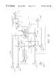
- FIG. 3is a block diagram of a wireless communications system showing a multipath signal environment.
- FIG. 3shows the user 104 , the handset 102 , the handset antenna 103 , the base station 110 , the base station antenna 106 , the radiating element 210 , the uplink path 114 , the wave 205 and the E vector 204 , as shown in FIG. 2 .
- the uplink path 114which can be described as a direct path from the handset 102 to the base station 110
- FIG. 3also shows an indirect path from the handset 102 the base station 110 .
- the indirect pathcomprises a bistatic path 322 and a reflected path 324
- the bistatic path 322(or bistatic ray 322 using the terminology of Geometrical 311 corresponds to an EM wave 308 that propagates from the handset 102 to a diffraction point 311 located on a structure 310 .
- the reflected path 324corresponds to an EM wave 312 that propagates from the diffraction point 311 to the base station antenna 106 .
- the EM wave 308has an E vector 309 that is typically coplanar with the handset antenna 103 .
- the EM wave 312has an E vector 314 that is, in general, not coplanar with the handset antenna 103 because the physical mechanism of diffraction at the diffraction point 311 will typically rotate the E vector 314 in diverse ways.
- the total EM wave 316 that arrives at the base station antenna 106is the sum (superposition) of the direct EM wave 205 and the reflected EM wave 312 .
- the total field E T 317will vary in strength and polarization depending on the relative direction and phase of the fields E R 314 and E D 204 .
- the variation in strength of the total field E T 317is known as amplitude fading and will be most pronounced when the vectors E R 314 and E D 204 have the same amplitude and polarization but are 180 degrees out of phase.
- the field E R 314is said to cancel the field E D 204 (or vice versa) and thus the total field E T 317 is zero at that point in space.
- S R ⁇ S Dcancellation can only occur at discrete points in space. If the total field E T 317 is zero at the antenna element 210 , it will, in general, not be zero at an antenna element 330 located a few wavelengths away from the antenna element 210 .
- using more than one antennacan often mitigate amplitude fading.
- the use of more than one antennais known as position-diversity.
- the variation in polarization of the total field E T 317is known as polarization fading and will be most pronounced when the vectors E R 314 and E D 204 have similar amplitudes but point in different polarization. Under these conditions, the vectors E R 314 and E D 204 will combine to produce a total field E T 317 that has a polarization intermediate to the polarization of the fields vectors E R 314 and E D 204 .
- a typical antenna element designed for linear polarizationsuch as the base station antenna elements 210 and 330 , receives maximum power when the polarization of the incident E field matches the polarization of the antenna element.
- a typical antenna element designed for linear polarizationreceives minimum energy when the polarization of the incident E field is cross-polarized to (i.e., orthogonal to) the polarization of the antenna.
- the antenna element 210is a vertical wire antenna, such, for example, a vertical dipole or a vertical monopole, then the antenna element 210 will receive maximum energy when the total field E T 317 is vertical, and minimum energy when the total field E T 317 is horizontal. Since the system shown in FIG. 3 is a duplex system, having a receiver at each end, the multipath fading can occur at either end.
- Duplex communication systemsare designed and constructed such that the uplink functions and downlink functions are multiplexed in some manner so that interference between uplink data transfers and downlink data transfers is minimized to an acceptable level.
- Common multiplexing techniquesinclude frequency multiplexing (e.g. Frequency Division Multiple Access (FDMA)), code multiplexing (e.g. Code Division Multiple Access (CDMA)), and time multiplexing (e.g. Time Division Multiple Access).
- FDMAFrequency Division Multiple Access
- CDMACode Division Multiple Access
- time multiplexinge.g. Time Division Multiple Access
- TDDTime Division Duplexing
- FIG. 4is a timing diagram showing the operation of a TDD system comprising the handset 102 and the base station 110 .
- the handset 103operates in a transmit state 402 to transmit data to the base station 110 that is operating in a receive state 410 .
- the handheld unitoperates in a receive state 402 to receive data from the base station 110 , which is operating in a transmitting state 404 .
- the handset and base stationcontinue alternating transmit and receive states such that during time interval T n , the handset 103 is operating in a transmit state 406 and the base unit 110 is operating in a receive state 414 .
- T n+1During a time interval T n+1 , the handset is operating in a transmit state 408 and the base unit 110 is operating in a receive state 412 . If the time intervals T 1 . . . T n+1 are short enough, the user 104 will not be aware that the handset is alternating between transmit and receive modes.
- Time Division Duplexed (TDD) systemscan take particular advantage of antenna diversity by applying the diversity during both the transmit and the receive phases of communication. This is possible because TDD systems typically transmit and receive on the same, or closely spaced, carrier frequencies, and the duration between the receive and transmit times intervals can be designed to be short in comparison to the expected rate of change in the path between transmitter and receiver. With short duplex separations, the propagation conditions for both uplink and downlink are more or less the same, which implies that the antenna that was best during the uplink phase (when the base station is receiving) will probably be very good during the downlink phase (when the base station is transmitting). Thus, by using transmit diversity at the base station, the mobile unit can reap the benefits of having antenna (receive-side) diversity with only one antenna This approach is very cost-effective since the base station absorbs the cost of antenna diversity and shares its diversity with all of the mobile units.
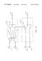
- FIG. 5is a block diagram of a wireless communication system with a base station antenna that provides three-axis polarization-diversity in coordination with TDD.
- FIG. 5shows the handset 102 , the handset antenna 103 , and the base station 110 .
- the handset antenna 103is aligned parallel to a vector E A .
- the base station 110has three antenna elements comprising an x-directed element 520 , a y-directed element 524 , and a z-directed element 522 .
- the x-directed element 520transmits and receives linearly polarized EM waves having a polarization E x .
- the y-directed element 524transmits and receives linearly polarized EM waves having a polarization E y .
- the z-directed element 522transmits and receives linearly polarized EM waves having a polarization E z .
- FIG. 5also shows the uplink path 320 , the wave 506 and the E vector 204 , as shown in FIGS. 2 and 3.
- FIG. 5also shows the indirect path from the handset 102 to the base station 110 comprising the bistatic path 522 , the reflected path 324 , the EM wave 308 , and the EM wave 312 .
- the total field E T 317will vary in strength and polarization depending on the relative direction and phase of the fields E R 314 and E D 204 .
- the total field E T 317is received by each of the antenna elements 520 , 522 and 524 where each antenna element produces an RF signal according to the portion of the total field E T 317 that is aligned with that element.
- the x-directed antenna element 320will be polarization matched to the field E Tx and will thus not experience polarization fading with respect to the E Tx field. Stated differently, the x-directed antenna element 320 receives the E Tx field component of the total field E T 317 . Similarly, the y-directed element 324 receives the E Ty field component and the z-directed element 522 receives the E Tz directed component.
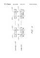
- FIG. 6Ais a block diagram that illustrates one embodiment of the signal processing used in the base station 110 to connect the antenna elements 520 , 522 , and 524 to a base station transceiver 628 .
- Each of the antenna elements 520 , 522 and 524provides an independent input/output port of a multiport antenna 609 .
- the multiport antenna 609is a three-port antenna, having three degrees of freedom, corresponding to the three independent ports.
- the signal processing system shown in FIG. 6Auses a three-pole double throw (3PDT) transmit-receive (T/R) switch 610 to allow the antenna elements 520 , 522 and 524 to be used for both transmitting and receiving.
- 3PDTthree-pole double throw
- T/Rtransmit-receive
- An output of the antenna element 522is provided to a first pole 611 of the T/R switch 610 .
- An output of the antenna element 320is provided to a second pole 612 of the T/R switch 610 .
- An output of the antenna element 324is provided to a third pole 612 of the T/R switch 610 .
- a first throw of the first pole 611is provided to a z input of a diversity combiner 622 .
- a first throw of the second pole 612is provided to an x input of the diversity combiner 622 .
- a first throw of the third pole 613is provided to a y input of the diversity combiner 622 .
- An output of the diversity combiner 622is provided to a receiver input of the transceiver 628 .
- a control output of the diversity combiner 622is provided to a control input of a diversity resolver 624 .
- a transmitter output of the transceiver 628is provided to a transmit signal input of the diversity resolver 624 .
- a z output of the diversity resolver 624is provided to a second throw of the pole 611 .
- An x output of the diversity resolver 624is provided to a second throw of the pole 612 .
- a y output of the diversity resolver 624is provided to a second throw of the pole 613 .
- a transmit-receive (T/R) output of the transceiver 628is provided to a T/R input of the diversity combiner 622 and to a control input of the T/R switch 610 .
- the transceiveris a TDD transceiver that switches between receiving and transmitting modes.
- the transceiver 628places the T/R switch 610 and the diversity resolver 622 in receiving mode as well.
- the T/R switch 610connects the antenna elements 522 , 520 and 524 to the respective z, x, and y inputs of the diversity resolver 622 .
- the diversity combiner 622detects aspects of the polarization state of the total field E T 317 by comparing the x, y, and z input signals provided by the antenna elements 522 , 520 , and 524 .
- the diversity combineruses the information about the polarization state to combine the x, y, and z input signals and thereby produce an output signal that is provided to the transceiver 628 .
- the diversity combineralso provides a control signal to the diversity resolver 624 .
- An embodiment of an antenna-switching diversity combiner and resolver,are described in the text accompanying FIG. 9 .
- An embodiment of a maximal ratio combining diversity combiner and resolverare described in the text accompanying FIG. 10 .
- the transceiver 628When the transceiver 628 switches to transmit mode, the transceiver 628 places the T/R switch 610 and the diversity combiner 622 in transmit mode as well. In transmit mode, the T/R switch connects the x, y, and z outputs of the diversity resolver to the respective inputs of the antenna elements 520 , 522 , and 524 .
- the transceiveralso provides a transmit signal (e.g., an RF transmit signal) to the diversity resolver 624 .
- the diversity resolverprovides the transmit signal to the x, y and z outputs according to the control information provided by the diversity combiner 622 .
- the diversity resolver 624provides the output signals x, y and z such that the polarization of the total field transmitted by the antenna elements 520 , 522 , and 524 is similar to the polarization of the total incident field E T 317 .
- the transmitted fieldwill propagate back along the paths 320 , 324 , and 322 to the handset unit antenna 103 .
- the polarization distortions that occurred on the uplink path from the handset 102 to the base station 110will be largely “undone” as the EM waves propagate back along the path 320 , 324 , and 322 .
- the reciprocity theoremsays, in effect, that transmitting and receiving are interchangeable, thus, the total EM field arriving at the handset antenna 103 will be polarized in a manner similar to the polarization of the fields transmitted by the handset antenna 103 .
- the polarization of the field arriving at the handset antenna 103will match the polarization of the handset antenna 103 .
- the polarization of the field arriving at the handset antenna 103will not quite match the polarization of the handset antenna 103 because of errors in the diversity combiner 622 , errors in the diversity resolver 624 , differences in the transmit and receiver frequencies, and non-linearities in the system or the transmission medium.
- the polarization of the field arriving at the handset antenna 103will not quite match the handset antenna 103 because of changes in the paths 306 , 322 and 324 . Changes in the paths are possible due to time delays between the receiving mode and the transmitting mode and possible changes in carrier frequency between transmitting and receiving modes.
- Changesinclude, for example, changes in the propagation characteristics of the paths (e.g., atmospheric effects such as air currents, rain, etc.), changes in the location of the handset unit 102 (e.g., a user riding in a car), or changes in the diffraction point 311 . Any or all of these changes may cause changes in the paths 320 , 322 , 324 such that polarization effects in the uplink will be different than the polarization effects in the downlink. Reducing the time interval between the transmitting and receiving modes can reduce some of the time dependent changes in the paths.
- FIG. 6Bis a block diagram that illustrates an alternative embodiment of the signal processing used in the base station 110 to connect the antenna elements 520 , 522 , and 524 to a base station transceiver 628 .
- a signal processing system 630 shown in FIG. 6Bis similar to the signal processing system 600 shown in FIG. 6A, comprising the diversity combiner 622 and the diversity resolver 624 , except that the system 630 does not use a T/R switch. Rather, in the system 630 , outputs of the antenna elements 522 , 520 and 524 are provided directly to the z, x, and y inputs, respectively, of the diversity combiner.
- the z output of the diversity resolver 624is provided to a z-directed antenna element 634
- the x output of the diversity resolver 624is provided to an x-directed antenna element 636
- the y output of the diversity resolver 624is provided to a y-directed antenna element 638 .
- the antenna elements 640comprise a multiport antenna 640 that is used only for transmitting.
- the signal processing system 630is similar to the operation of the signal processing system 600 , except that the transceiver does not drive a T/R switch. Thus, the signal processing system 630 is, in some respects, simpler than the signal processing system 600 .
- the phase centers of the antennas 609 and 640are preferably close together so that the transmit and receive paths are similar. In embodiments where the phase centers of the antennas 609 and 640 are separated, then additional signal processing to compensate for the difference in phase centers may be provided by the base station 110 .
- FIG. 7is a diagram of one embodiment of a base station antenna 700 comprising a vertical dipole 701 and a horizontal loop 710 .
- the antenna 700provides two-axis polarization diversity based on E v (the vertical component of the total field ET 317 ) and E H (the horizontal component of E T 317 ).
- E vthe vertical component of the total field ET 317
- E Hthe horizontal component of E T 317 .
- the use of horizontal and vertical componentsis convenient because, in general, the total field E T 317 will be propagating in a direction that is primarily horizontal. This is especially true when the handset 102 is located at some distance from the base station antenna 106 .
- the vertical dipole 701will efficiently receive EM waves propagating in a horizontal plane and having a vertical E-field.
- the horizontal loop 710will efficiently receive EM waves propagating in a vertical plane and having a horizontal E-field.
- the combination of the vertical dipole 701 and the horizontal loop 710provides an efficient two-port antenna for receiving EM waves propagating in a substantially horizontal plane.
- FIG. 8is a system block diagram of a communications system that provides two-axis polarization diversity using the two-port antenna 700 .
- the signal processing system shown in FIG. 8uses a two-pole double throw (2PDT) transmit-receive (T/R) switch 812 to allow the antenna elements 701 and 710 to be used for both transmitting and receiving.
- An output of the antenna element 701is provided to a first pole 810 of the T/R switch 812 .
- An output of the antenna element 710is provided to a second pole 611 of the T/R switch 812 .
- a first throw of the first pole 810is provided to a vertical input of a diversity combiner 814 .
- a first throw of the second pole 811is provided to a horizontal input of the diversity combiner 814 .
- An output of the diversity combiner 814is provided to a receiver input of the transceiver 628 .
- a control output of the diversity combiner 814is provided to a control input of a diversity resolver 816 via a control bus 815 .
- a transmitter output of the transceiver 628is provided to a transmitter signal input of the diversity resolver 816 .
- a vertical output of the diversity resolver 816is provided to a second throw of the pole 810 .
- a horizontal output of the diversity resolver 816is provided to a second throw of the pole 811 .
- a transmit-receive (T/R) output of the transceiver 628is provided to a T/R input of the diversity combiner 814 and to a control input of the T/R switch 812 .
- the diversity combiner 814determines aspects of the polarization state of an EM wave received by the antenna 700 .
- the diversity combinercombines the horizontal and vertical input signals received from the antenna 700 and provides the combined signal to the receiver input of the transceiver 628 .
- the diversity combiner 814provides polarization information regarding the polarization of the incident EM wave to the diversity resolver 816 via the control bus 815 .
- the polarization informationcan include, for example, weighting functions and/or phase information.
- the diversity combinermay use any suitable means for extracting phase information and combining the horizontal and vertical inputs, including, for example, antenna switching and maximal ratio combining.
- FIG. 9is a block diagram of a two-channel diversity combiner 902 and a two-channel diversity resolver 904 that provide antenna-switching diversity.
- the diversity combiner 902is an example of one embodiment of the diversity combiner 814 .
- the two-channel diversity combiner 902can be expanded to three channels and used as an embodiment of diversity combiner 622 shown in FIGS. 6A and 6B.
- the diversity resolvercan be expanded to three channels and used as an embodiment of the diversity resolver 624 .
- the combiner 902receives a first input 910 from a first antenna and a second input 912 from a second antenna.
- the first and second antennasmay, for example, be antennas designed for vertical and horizontal polarization such as the antennas 701 and 710 respectively.
- the first input 910is provided to an input of a first amplitude calculator 914 and to a first throw of a single pole double throw (SPDT) switch 920 .
- the second input 912is provided to and input of a second amplitude calculator 916 and to a second throw of the SPDT switch 920 .
- An output of the first amplitude calculator 914is provided to a first input of a comparator 918 and an output of the amplitude calculator 916 is provided to a second input of the comparator 918 .
- An output of the comparator 918is provided to a control input of the SPDT switch 920 and to a control input of a SPDT switch 932 .
- the pole of the SPDT switch 920is provided to a receiver output 922 .
- a transmitter input 930is provided to the pole of the SPDT switch 932 .
- a first pole of the SPDT switch 932is provided to a first antenna output 934 and a second pole of the SPDT switch 932 is provided to a second antenna output 936 .
- the diversity combiner 902comprising the amplitude calculators 914 and 916 , the comparator 918 , and the SPDT switch 920 , computes the amplitudes of the first and second inputs 910 and 912 .
- the comparator 918selects the larger of the two amplitudes and directs the SPDT switch 920 to select the input corresponding to the largest amplitude.
- the comparator 918also directs the switch 932 to select the output corresponding to the larger of the two inputs.
- FIG. 10is a block diagram of a two-channel diversity combiner 1002 and a two-channel diversity resolver 1004 that use Maximal Ratio Combining.
- the diversity combiner 1002may be used as an embodiment of the diversity combiner 814 .
- the two-channel diversity combiner 1002can be expanded to three channels and used as an embodiment of the diversity combiner 622 shown in FIGS. 6A and 6B.
- the diversity resolver 1004can be used as an embodiment of the diversity resolvers 816 and 624 .
- MRCa weight (amplitude) and a phase is computed for each antenna elements.
- FIG. 10is also applicable to describe a closely related technique called Equal Gain Combining (EGC) wherein each element is accorded the same gain.
- EGCEqual Gain Combining
- the combiner 1002receives a first input 1010 from a first antenna and a second input 1012 from a second antenna.
- the first and second antennasmay, for example, be antennas designed for vertical and horizontal polarization such as the antennas 701 and 710 respectively.
- the first input 1010is provided to a first input of a normalization block 1014 , an input of a gain control block 1016 , a first input of a phase comparator 1020 and a first input of an adder 1024 .
- the second input 1012is provided to a second input of the normalization block 1014 , an input of a gain control block 1018 , a second input of the phase comparator 1020 and a signal input of a phase shifter 1022 .
- An output of the normalization block 1014is provided to a control input of the gain control block 1016 and a control input of the gain control block 1018 .
- An output of the phase comparator 1020is provided to a phase control input of the phase shifter 1022 .
- a signal output of the phase shifter 1022is provided to a second input of the adder 1024 .
- An output of the adder 1024is provided to a receiver output 1026 .
- a transmitter input 1030is provided to a signal input of a phase shifter 1032 and to an input of a gain control block 1034 .
- An output of the gain control block 1018is provided to a control input of the gain control block 1034 .
- a signal output of the phase shifter 1032is provided to an input of a gain control block 1036 .
- An output of the gain control block 1016is provided to a control input of the gain control block 1036 .
- An output of the gain control block 1036is provided as a first antenna output and an output of the gain control block 1034 is provided as a second antenna output.
- the diversity combiner 1002comprising the normalization block 1014 , the gain control blocks 1016 and 1018 , the phase comparator 1020 , the phase shifter 1022 and the adder 1024 , detects the relative amplitude and phase of the two input signals 1010 and 1012 .
- the normalized amplitudes w 1 and w 2are provided to the gain control blocks 1036 and 1034 so that the relative amplitudes of the outputs 1038 and 1040 are the same as the relative amplitudes of the inputs 1010 and 1012 respectively.
- the weights w nare used directly, in a transmitting context the weights w n are squared, such that each element is weighted by w 2 n .
- the phase comparator 1020determines the relative phase of the two inputs 1010 and 1012 and directs the phase shifter 1022 to adjust the phase of the second input 1012 so that the two inputs of the adder 1024 are in-phase. Since the inputs of the adder 1024 are in-phase, the output of the adder is maximized. Moreover, since the noise in the two inputs 1010 and 1012 is typically uncorrelated, the adder will have the tendency to average the noise components in the two inputs and thereby reduce the total noise in the output signal 1026 , thus improving the SNR. In some embodiments, the phase comparator 1020 and phase shifter 1022 are implemented using a phase-locked loop.
- the phase comparator 1020also directs the phase shifter 1032 to adjust the phase of the input to the gain control block 1036 such that the outputs 1038 and 1040 share the same phase relationship as the two inputs 1010 and 1012 , except that the phases are reversed upon transmit.
- a first channel path from the handset to a first element of the base station antennaintroduces a 30 degree phase advance with respect to a second antenna element having a second channel path from the handset.
- Reciprocityimplies that the base station should retard, by 30 degrees, the phase of transmission from the first antenna element with respect to the transmission phase of the second antenna element, because the signal will itself experience a (relative) channel-path advancement of 30 degrees in propagating back to the handset.
- the outputs 1038 and 1040By adjusting the relative amplitudes and phases of the outputs 1038 and 1040 to match the relative amplitudes and phases of the inputs 1010 and 1012 , the outputs 1038 and 1040 , when fed to the first and second antennas, will produce a EM wave which as a polarization state similar to the polarization state of the received EM wave.
- the present inventioncan be used with other polarizations, such as, for example, circular polarization, elliptical polarization, etc.
- the present inventionis not limited to wire or loop antennas but may be implemented using any radiating structures or combinations of radiating structures, including, for example, reflector antennas, phased arrays, horns, waveguide apertures, dipoles, dielectric antennas, leaky-wave antennas, inverted F antennas, patch antennas, slot antennas, radiating apertures, spiral antennas, helical antennas, log-periodic antennas, monopoles, etc.
- an electromagnetic transducerrefers generally to an electromagnetic transducer, and thus includes all electromagnetic transducers, such as, for example, coils, superconducting devices, photonic devices, detectors, etc.
- radio frequency communication systemsAlthough described primarily in terms of radio frequency communication systems, the present invention is not limited to radio frequency systems and may be used with any type of electromagnetic waves and any frequencies, including but not limited to, millimeter-wave frequencies, infrared frequencies, optical frequencies, ultraviolet frequencies, x-ray frequencies, etc.
- the diversity combiners 622 and 814 , and/or the diversity resolvers 624 and 816may provide adaptive algorithms and predictive algorithms to improve performance by predicting the desired polarization state of the transmitted EM waves based on the polarization state of the received EM waves.
- the present inventionis not limited to polarization diversity alone, and may be used in a base station that provides antenna-position diversity for receive and transmit functions.
- the antennas 522 , 520 , and 524may be positioned such that the phase centers of the antennas are separated by a few wavelengths.
- the antenna elements 522 , 520 , and 524may be aligned such that they are substantially parallel to one another.
- both antenna-position diversity and polarization-diversitymay be provided simultaneously by positioning the antenna elements such that each element has a different position and polarization. More than three channels may also be provided.
Landscapes
- Engineering & Computer Science (AREA)
- Computer Networks & Wireless Communication (AREA)
- Signal Processing (AREA)
- Radio Transmission System (AREA)
- Mobile Radio Communication Systems (AREA)
Abstract
Description
Claims (35)
Priority Applications (1)
| Application Number | Priority Date | Filing Date | Title |
|---|---|---|---|
| US09/103,417US6411824B1 (en) | 1998-06-24 | 1998-06-24 | Polarization-adaptive antenna transmit diversity system |
Applications Claiming Priority (1)
| Application Number | Priority Date | Filing Date | Title |
|---|---|---|---|
| US09/103,417US6411824B1 (en) | 1998-06-24 | 1998-06-24 | Polarization-adaptive antenna transmit diversity system |
Publications (1)
| Publication Number | Publication Date |
|---|---|
| US6411824B1true US6411824B1 (en) | 2002-06-25 |
Family
ID=22295067
Family Applications (1)
| Application Number | Title | Priority Date | Filing Date |
|---|---|---|---|
| US09/103,417Expired - LifetimeUS6411824B1 (en) | 1998-06-24 | 1998-06-24 | Polarization-adaptive antenna transmit diversity system |
Country Status (1)
| Country | Link |
|---|---|
| US (1) | US6411824B1 (en) |
Cited By (85)
| Publication number | Priority date | Publication date | Assignee | Title |
|---|---|---|---|---|
| US20010004605A1 (en)* | 1999-12-21 | 2001-06-21 | Matsushita Electric Industrial Co., Ltd. | Radio transmission apparatus and radio reception apparatus |
| US20020002037A1 (en)* | 2000-03-30 | 2002-01-03 | Hiroki Ito | Radio communication apparatus and radio communication method |
| US20020024975A1 (en)* | 2000-03-14 | 2002-02-28 | Hillel Hendler | Communication receiver with signal processing for beam forming and antenna diversity |
| US20020115409A1 (en)* | 2001-02-21 | 2002-08-22 | Khayrallah Ali S. | Method to achieve diversity in a communication network |
| US20020136287A1 (en)* | 2001-03-20 | 2002-09-26 | Heath Robert W. | Method, system and apparatus for displaying the quality of data transmissions in a wireless communication system |
| US20020198026A1 (en)* | 2001-06-20 | 2002-12-26 | Nokia Corporation | Method, communications system, and base station for transmitting signals with transmit diversity |
| US20030043929A1 (en)* | 2001-09-06 | 2003-03-06 | Hemanth Sampath | Transmit signal preprocessing based on transmit antennae correlations for muliple antennae systems |
| US20030067890A1 (en)* | 2001-10-10 | 2003-04-10 | Sandesh Goel | System and method for providing automatic re-transmission of wirelessly transmitted information |
| US20030097658A1 (en)* | 2000-08-16 | 2003-05-22 | Richards William R. | Method and apparatus for simultaneous live television and data services using single beam antennas |
| US20030099304A1 (en)* | 2001-11-28 | 2003-05-29 | Dhananjay Gore | System and method for transmit diversity base upon transmission channel delay spread |
| US20030109283A1 (en)* | 2000-01-27 | 2003-06-12 | Joseph Shapira | Cellular base station augmentation system and method |
| US20030114194A1 (en)* | 2000-12-21 | 2003-06-19 | Katsuhiko Hiramatsu | Base station device |
| US20030161281A1 (en)* | 2000-11-07 | 2003-08-28 | Dulin David R. | System and method for data transmission from multiple wireless base transceiver stations to a subscriber unit |
| US20030235252A1 (en)* | 2002-06-19 | 2003-12-25 | Jose Tellado | Method and system of biasing a timing phase estimate of data segments of a received signal |
| EP1394962A1 (en) | 2002-08-27 | 2004-03-03 | Nortel Networks Limited | Method for transmission of radio signals with polarization diversity |
| US20040053582A1 (en)* | 2000-12-15 | 2004-03-18 | Kiyoshi Nakanishi | Portable radio device having antenna switching function |
| US20040082311A1 (en)* | 2002-10-28 | 2004-04-29 | Shiu Da-Shan | Utilizing speed and position information to select an operational mode in a wireless communication system |
| US20040121807A1 (en)* | 2002-12-20 | 2004-06-24 | Alcatel | Fixed transmitting station with electromagnetic field probe |
| US20040156339A1 (en)* | 2003-02-12 | 2004-08-12 | Andrew Urquhart | Antenna diversity |
| US20040192395A1 (en)* | 2003-03-24 | 2004-09-30 | Karabinis Peter D. | Co-channel wireless communication methods and systems using nonsymmetrical alphabets |
| US20050130622A1 (en)* | 2001-09-04 | 2005-06-16 | Alessandro Striuli | Access network for mobile telecommunications and method for developing radio coverage |
| US20050221818A1 (en)* | 2004-03-31 | 2005-10-06 | The Boeing Company | Dynamic configuration management |
| WO2005099129A1 (en)* | 2004-04-08 | 2005-10-20 | Karayil Thekkoott Narayanan Ma | Method to design polarization arrangements for mimo antennas using state of polarization as parameter |
| US6963619B1 (en)* | 2000-07-21 | 2005-11-08 | Intel Corporation | Spatial separation and multi-polarization of antennae in a wireless network |
| US20060116182A1 (en)* | 2004-11-30 | 2006-06-01 | Bekritsky Benjamin J | Technique for sharing WLAN and WPAN antennas |
| US20060133549A1 (en)* | 2002-03-26 | 2006-06-22 | Shilpa Talwar | Robust multiple chain receiver |
| US20060211395A1 (en)* | 2005-03-15 | 2006-09-21 | Intel Corporation | Apparatus and method of detecting pilot carriers received on a fading channel |
| US20070025376A1 (en)* | 2001-06-29 | 2007-02-01 | Bernheim Henrik F | System and method for virtual sector provisioning and network configuration |
| CN1320784C (en)* | 2003-03-26 | 2007-06-06 | 三星电子株式会社 | Device and method for executing demodulaton operution in mobile communication system based on emission diversity |
| US7236807B1 (en)* | 1999-10-28 | 2007-06-26 | Celletra Ltd. | Cellular base station augmentation |
| US20070152867A1 (en)* | 2006-01-03 | 2007-07-05 | Mitch Randall | Polarization and frequency diverse radar system for complete polarimetric characterization of scatterers with increased scanning speed |
| US20080013445A1 (en)* | 2006-07-15 | 2008-01-17 | Kazimierz Siwiak | Wireless communication system and method with elliptically polarized radio frequency signals |
| US20080119190A1 (en)* | 2003-03-24 | 2008-05-22 | Mobile Satellite Ventures, Lp | Co-channel wireless communication methods and systems using relayed wireless communications |
| US20080117307A1 (en)* | 2003-10-01 | 2008-05-22 | Canon Kabushiki Kaisha | Image capture apparatus, image display method, and program |
| WO2008111075A3 (en)* | 2007-03-13 | 2008-12-11 | Petratec Int Ltd | Antenna assembly for service station |
| US20090045978A1 (en)* | 2005-10-24 | 2009-02-19 | Petratec International Ltd. | Devices and Methods Useful for Authorizing Purchases Associated with a Vehicle |
| US20090051618A1 (en)* | 2007-08-22 | 2009-02-26 | Samsung Electronics Co., Ltd. | Multiple input multiple output (mimo) antenna system adaptable for environmental multiplicity |
| US20090207093A1 (en)* | 2008-02-15 | 2009-08-20 | Qualcomm Incorporated | Methods and apparatus for using multiple antennas having different polarization |
| US7586873B2 (en) | 2000-09-01 | 2009-09-08 | Intel Corporation | Wireless communications system that supports multiple modes of operation |
| US20090224990A1 (en)* | 2008-03-06 | 2009-09-10 | Qualcomm Incorporated | Methods and apparatus for supporting communications using a first polarization direction electrical antenna and a second polarization direction magnetic antenna |
| US20090224847A1 (en)* | 2008-03-06 | 2009-09-10 | Qualcomm Incorporated | Methods and apparatus for supporting communications using antennas associated with different polarization directions |
| US20090253375A1 (en)* | 2005-12-20 | 2009-10-08 | Fachhochschule Aachen | Dual Mode Funk |
| US20090289113A1 (en)* | 2005-10-24 | 2009-11-26 | Petratec International Ltd. | System and Method for Autorizing Purchases Associated with a Vehicle |
| US20090315759A1 (en)* | 2008-06-23 | 2009-12-24 | Hong Kong Applied Science And Technology Research Institute Co., Ltd. | Direction Finding Antenna Systems and Methods for Use Thereof |
| US20100001904A1 (en)* | 2008-07-02 | 2010-01-07 | Fujitsu Limited | Radio communication apparatus and system |
| US20100003034A1 (en)* | 2007-01-30 | 2010-01-07 | Georgia Tech Research Corporation | Systems and methods for adaptive polarization transmission |
| US20100141403A1 (en)* | 2007-01-25 | 2010-06-10 | Petratec International Ltd. | Devices and methods useful for authorizing purchases associated with a vehicle |
| US20100202565A1 (en)* | 2007-08-14 | 2010-08-12 | Rambus Inc. | Communication using continuous-phase modulated signals |
| US20100260076A1 (en)* | 2009-04-13 | 2010-10-14 | Viasat, Inc. | Half-Duplex Phased Array Antenna System |
| WO2010134860A1 (en)* | 2009-05-20 | 2010-11-25 | Telefonaktiebolaget L M Ericsson (Publ) | Methods and arrangements in a wireless communication system |
| US20100309056A1 (en)* | 2009-06-09 | 2010-12-09 | Ahmadreza Rofougaran | Method and system for scanning rf channels utilizing leaky wave antennas |
| US20110065449A1 (en)* | 2009-09-13 | 2011-03-17 | Robert Mitchell Zimmerman | Adaptive use of polarization as a means of increased wireless channel capacity |
| US20120201319A1 (en)* | 2010-10-05 | 2012-08-09 | Henrik Asplund | Method and arrangement for polarization control in a communication system |
| US20120252369A1 (en)* | 2009-12-16 | 2012-10-04 | Telefonaktiebolaget L M Ericsson (Publ) | Method and arrangement for coordinating polarizations in a wireless communication system |
| US20120300871A1 (en)* | 2011-05-26 | 2012-11-29 | Schroeder Werner L | Wireless device with extendable antenna |
| US8373514B2 (en) | 2007-10-11 | 2013-02-12 | Qualcomm Incorporated | Wireless power transfer using magneto mechanical systems |
| US8378523B2 (en) | 2007-03-02 | 2013-02-19 | Qualcomm Incorporated | Transmitters and receivers for wireless energy transfer |
| US8378522B2 (en) | 2007-03-02 | 2013-02-19 | Qualcomm, Incorporated | Maximizing power yield from wireless power magnetic resonators |
| US20130072125A1 (en)* | 2011-09-19 | 2013-03-21 | Broadcom Corporation | Switch for transmit/receive mode selection and antenna polarization diversity |
| US8447234B2 (en) | 2006-01-18 | 2013-05-21 | Qualcomm Incorporated | Method and system for powering an electronic device via a wireless link |
| CN103141035A (en)* | 2010-10-05 | 2013-06-05 | 瑞典爱立信有限公司 | Method and arrangement for polarization control in a communication system |
| US8482157B2 (en) | 2007-03-02 | 2013-07-09 | Qualcomm Incorporated | Increasing the Q factor of a resonator |
| US8629576B2 (en) | 2008-03-28 | 2014-01-14 | Qualcomm Incorporated | Tuning and gain control in electro-magnetic power systems |
| US20140038663A1 (en)* | 2012-08-03 | 2014-02-06 | Research In Motion Limited | Mobile wireless communications device with ddpdt rf switch and related methods |
| US8649747B1 (en)* | 2009-08-11 | 2014-02-11 | Netgear, Inc. | Dynamically adjusting antenna polarization in a wireless communication system |
| US8665069B2 (en) | 2007-10-19 | 2014-03-04 | Petratec International Ltd. | RFID tag especially for use near conductive objects |
| US8693970B2 (en) | 2009-04-13 | 2014-04-08 | Viasat, Inc. | Multi-beam active phased array architecture with independant polarization control |
| US8699626B2 (en) | 2011-11-29 | 2014-04-15 | Viasat, Inc. | General purpose hybrid |
| US8737531B2 (en) | 2011-11-29 | 2014-05-27 | Viasat, Inc. | Vector generator using octant symmetry |
| US8773219B2 (en) | 2009-04-13 | 2014-07-08 | Viasat, Inc. | Active hybrids for antenna system |
| US8879509B2 (en) | 2003-02-14 | 2014-11-04 | Apple Inc. | Antenna Diversity |
| CN104348536A (en)* | 2013-07-30 | 2015-02-11 | 瞻博网络公司 | Methods and apparatus for multi-polarization antenna systems |
| US20150089549A1 (en)* | 2007-10-09 | 2015-03-26 | Maxlinear, Inc. | Method and system for full spectrum capture for satellite and terrestrial applications |
| US9124120B2 (en) | 2007-06-11 | 2015-09-01 | Qualcomm Incorporated | Wireless power system and proximity effects |
| US9130602B2 (en) | 2006-01-18 | 2015-09-08 | Qualcomm Incorporated | Method and apparatus for delivering energy to an electrical or electronic device via a wireless link |
| US9601267B2 (en) | 2013-07-03 | 2017-03-21 | Qualcomm Incorporated | Wireless power transmitter with a plurality of magnetic oscillators |
| US9634402B2 (en)* | 2015-03-09 | 2017-04-25 | Trimble Inc. | Polarization diversity in array antennas |
| US9774086B2 (en) | 2007-03-02 | 2017-09-26 | Qualcomm Incorporated | Wireless power apparatus and methods |
| US20170294989A1 (en)* | 2014-09-01 | 2017-10-12 | China Academy Of Telecommunications Technology | Method and device for data transmission |
| US10516219B2 (en) | 2009-04-13 | 2019-12-24 | Viasat, Inc. | Multi-beam active phased array architecture with independent polarization control |
| US10998640B2 (en) | 2018-05-15 | 2021-05-04 | Anokiwave, Inc. | Cross-polarized time division duplexed antenna |
| US11139589B2 (en)* | 2018-10-25 | 2021-10-05 | The Boeing Company | Polarization uniqueness manipulation apparatus (PUMA) |
| US11349223B2 (en) | 2015-09-18 | 2022-05-31 | Anokiwave, Inc. | Laminar phased array with polarization-isolated transmit/receive interfaces |
| US11418971B2 (en) | 2017-12-24 | 2022-08-16 | Anokiwave, Inc. | Beamforming integrated circuit, AESA system and method |
| US11909497B2 (en)* | 2018-09-28 | 2024-02-20 | Sony Group Corporation | Indicating user equipment (UE) polorization tracking capacity |
Citations (17)
| Publication number | Priority date | Publication date | Assignee | Title |
|---|---|---|---|---|
| US4747160A (en)* | 1987-03-13 | 1988-05-24 | Suite 12 Group | Low power multi-function cellular television system |
| EP0342694A2 (en)* | 1988-05-20 | 1989-11-23 | Nec Corporation | Optical polarisation diversity receiver |
| US5491723A (en)* | 1993-05-06 | 1996-02-13 | Ncr Corporation | Wireless communication system having antenna diversity |
| US5548583A (en)* | 1992-11-24 | 1996-08-20 | Stanford Telecommuncations, Inc. | Wireless telephone user location capability for enhanced 911 application |
| GB2310109A (en)* | 1996-02-08 | 1997-08-13 | Orange Personal Comm Serv Ltd | Communication System Using Space and Polarization Diversity |
| US5701591A (en)* | 1995-04-07 | 1997-12-23 | Telecommunications Equipment Corporation | Multi-function interactive communications system with circularly/elliptically polarized signal transmission and reception |
| US5724666A (en)* | 1994-03-24 | 1998-03-03 | Ericsson Inc. | Polarization diversity phased array cellular base station and associated methods |
| US5771449A (en)* | 1994-03-17 | 1998-06-23 | Endlink, Inc. | Sectorized multi-function communication system |
| US5784032A (en)* | 1995-11-01 | 1998-07-21 | Telecommunications Research Laboratories | Compact diversity antenna with weak back near fields |
| US5884192A (en)* | 1994-06-03 | 1999-03-16 | Telefonaktiebolaget Lm Ericsson | Diversity combining for antennas |
| US5903238A (en)* | 1996-09-20 | 1999-05-11 | Siemens Aktiengesellschaft | Radio station for mobile communication systems and method for the selection of a transmission means |
| US5933788A (en)* | 1996-04-29 | 1999-08-03 | Siemens Aktiengesellschaft | Radio station for transmitting and receiving digital information in a mobile communications system |
| US5963874A (en)* | 1995-09-29 | 1999-10-05 | Telefonaktiebolaget Lm Ericsson | Radio station arranged for space-diversity and polarization diversity reception |
| US5999826A (en)* | 1996-05-17 | 1999-12-07 | Motorola, Inc. | Devices for transmitter path weights and methods therefor |
| US6018317A (en)* | 1995-06-02 | 2000-01-25 | Trw Inc. | Cochannel signal processing system |
| US6043790A (en)* | 1997-03-24 | 2000-03-28 | Telefonaktiebolaget Lm Ericsson | Integrated transmit/receive antenna with arbitrary utilization of the antenna aperture |
| US6172970B1 (en)* | 1997-05-05 | 2001-01-09 | The Hong Kong University Of Science And Technology | Low-complexity antenna diversity receiver |
- 1998
- 1998-06-24USUS09/103,417patent/US6411824B1/ennot_activeExpired - Lifetime
Patent Citations (17)
| Publication number | Priority date | Publication date | Assignee | Title |
|---|---|---|---|---|
| US4747160A (en)* | 1987-03-13 | 1988-05-24 | Suite 12 Group | Low power multi-function cellular television system |
| EP0342694A2 (en)* | 1988-05-20 | 1989-11-23 | Nec Corporation | Optical polarisation diversity receiver |
| US5548583A (en)* | 1992-11-24 | 1996-08-20 | Stanford Telecommuncations, Inc. | Wireless telephone user location capability for enhanced 911 application |
| US5491723A (en)* | 1993-05-06 | 1996-02-13 | Ncr Corporation | Wireless communication system having antenna diversity |
| US5771449A (en)* | 1994-03-17 | 1998-06-23 | Endlink, Inc. | Sectorized multi-function communication system |
| US5724666A (en)* | 1994-03-24 | 1998-03-03 | Ericsson Inc. | Polarization diversity phased array cellular base station and associated methods |
| US5884192A (en)* | 1994-06-03 | 1999-03-16 | Telefonaktiebolaget Lm Ericsson | Diversity combining for antennas |
| US5701591A (en)* | 1995-04-07 | 1997-12-23 | Telecommunications Equipment Corporation | Multi-function interactive communications system with circularly/elliptically polarized signal transmission and reception |
| US6018317A (en)* | 1995-06-02 | 2000-01-25 | Trw Inc. | Cochannel signal processing system |
| US5963874A (en)* | 1995-09-29 | 1999-10-05 | Telefonaktiebolaget Lm Ericsson | Radio station arranged for space-diversity and polarization diversity reception |
| US5784032A (en)* | 1995-11-01 | 1998-07-21 | Telecommunications Research Laboratories | Compact diversity antenna with weak back near fields |
| GB2310109A (en)* | 1996-02-08 | 1997-08-13 | Orange Personal Comm Serv Ltd | Communication System Using Space and Polarization Diversity |
| US5933788A (en)* | 1996-04-29 | 1999-08-03 | Siemens Aktiengesellschaft | Radio station for transmitting and receiving digital information in a mobile communications system |
| US5999826A (en)* | 1996-05-17 | 1999-12-07 | Motorola, Inc. | Devices for transmitter path weights and methods therefor |
| US5903238A (en)* | 1996-09-20 | 1999-05-11 | Siemens Aktiengesellschaft | Radio station for mobile communication systems and method for the selection of a transmission means |
| US6043790A (en)* | 1997-03-24 | 2000-03-28 | Telefonaktiebolaget Lm Ericsson | Integrated transmit/receive antenna with arbitrary utilization of the antenna aperture |
| US6172970B1 (en)* | 1997-05-05 | 2001-01-09 | The Hong Kong University Of Science And Technology | Low-complexity antenna diversity receiver |
Cited By (177)
| Publication number | Priority date | Publication date | Assignee | Title |
|---|---|---|---|---|
| US7236807B1 (en)* | 1999-10-28 | 2007-06-26 | Celletra Ltd. | Cellular base station augmentation |
| US20010004605A1 (en)* | 1999-12-21 | 2001-06-21 | Matsushita Electric Industrial Co., Ltd. | Radio transmission apparatus and radio reception apparatus |
| US7062245B2 (en)* | 1999-12-21 | 2006-06-13 | Matsushita Electric Industrial Co., Ltd. | Radio transmission apparatus and radio reception apparatus |
| US6987990B2 (en)* | 2000-01-27 | 2006-01-17 | Celletra Ltd. | Cellular base station augmentation system and method |
| US20030109283A1 (en)* | 2000-01-27 | 2003-06-12 | Joseph Shapira | Cellular base station augmentation system and method |
| US20020024975A1 (en)* | 2000-03-14 | 2002-02-28 | Hillel Hendler | Communication receiver with signal processing for beam forming and antenna diversity |
| US7298715B2 (en)* | 2000-03-14 | 2007-11-20 | Vyyo Ltd | Communication receiver with signal processing for beam forming and antenna diversity |
| US20020002037A1 (en)* | 2000-03-30 | 2002-01-03 | Hiroki Ito | Radio communication apparatus and radio communication method |
| US6963619B1 (en)* | 2000-07-21 | 2005-11-08 | Intel Corporation | Spatial separation and multi-polarization of antennae in a wireless network |
| US7921442B2 (en)* | 2000-08-16 | 2011-04-05 | The Boeing Company | Method and apparatus for simultaneous live television and data services using single beam antennas |
| US20030097658A1 (en)* | 2000-08-16 | 2003-05-22 | Richards William R. | Method and apparatus for simultaneous live television and data services using single beam antennas |
| US8428037B2 (en) | 2000-09-01 | 2013-04-23 | Intel Corporation | Wireless communications system that supports multiple modes of operation |
| US20100046429A1 (en)* | 2000-09-01 | 2010-02-25 | Heath Jr Robert W | Wireless Communications System That Supports Multiple Modes Of Operation |
| US9288800B2 (en) | 2000-09-01 | 2016-03-15 | Intel Corporation | Wireless communications system that supports multiple modes of operation |
| US20100142636A1 (en)* | 2000-09-01 | 2010-06-10 | Heath Jr Robert W | Wireless communications system that supports multiple modes of operation |
| US9736832B2 (en) | 2000-09-01 | 2017-08-15 | Intel Corporation | Wireless communications system that supports multiple modes of operation |
| US8345637B2 (en) | 2000-09-01 | 2013-01-01 | Intel Corporation | Wireless communications system that supports multiple modes of operation |
| US7586873B2 (en) | 2000-09-01 | 2009-09-08 | Intel Corporation | Wireless communications system that supports multiple modes of operation |
| US20030161281A1 (en)* | 2000-11-07 | 2003-08-28 | Dulin David R. | System and method for data transmission from multiple wireless base transceiver stations to a subscriber unit |
| US7397804B2 (en) | 2000-11-07 | 2008-07-08 | Intel Corporation | System and method for synchronizing data transmission from multiple wireless base transceiver stations to a subscriber unit |
| US20040053582A1 (en)* | 2000-12-15 | 2004-03-18 | Kiyoshi Nakanishi | Portable radio device having antenna switching function |
| US20030114194A1 (en)* | 2000-12-21 | 2003-06-19 | Katsuhiko Hiramatsu | Base station device |
| US20050282587A1 (en)* | 2000-12-21 | 2005-12-22 | Matsushita Electric Industrial Co., Ltd. | Base station apparatus with reception and diversity weight combining |
| US7003324B2 (en)* | 2000-12-21 | 2006-02-21 | Matsushita Electric Industrial Co., Ltd. | Base station apparatus with reception and diversity weight combining |
| US7113745B2 (en)* | 2001-02-21 | 2006-09-26 | Ericsson Inc. | Method to achieve diversity in a communication network |
| US20020115409A1 (en)* | 2001-02-21 | 2002-08-22 | Khayrallah Ali S. | Method to achieve diversity in a communication network |
| US20020136287A1 (en)* | 2001-03-20 | 2002-09-26 | Heath Robert W. | Method, system and apparatus for displaying the quality of data transmissions in a wireless communication system |
| US20020198026A1 (en)* | 2001-06-20 | 2002-12-26 | Nokia Corporation | Method, communications system, and base station for transmitting signals with transmit diversity |
| US20070025376A1 (en)* | 2001-06-29 | 2007-02-01 | Bernheim Henrik F | System and method for virtual sector provisioning and network configuration |
| US20050130622A1 (en)* | 2001-09-04 | 2005-06-16 | Alessandro Striuli | Access network for mobile telecommunications and method for developing radio coverage |
| US7177666B2 (en)* | 2001-09-04 | 2007-02-13 | Itec S.R.L. | Access network for mobile telecommunications and method for developing radio coverage |
| US7149254B2 (en) | 2001-09-06 | 2006-12-12 | Intel Corporation | Transmit signal preprocessing based on transmit antennae correlations for multiple antennae systems |
| US20030043929A1 (en)* | 2001-09-06 | 2003-03-06 | Hemanth Sampath | Transmit signal preprocessing based on transmit antennae correlations for muliple antennae systems |
| US20030067890A1 (en)* | 2001-10-10 | 2003-04-10 | Sandesh Goel | System and method for providing automatic re-transmission of wirelessly transmitted information |
| US20030099304A1 (en)* | 2001-11-28 | 2003-05-29 | Dhananjay Gore | System and method for transmit diversity base upon transmission channel delay spread |
| US7336719B2 (en) | 2001-11-28 | 2008-02-26 | Intel Corporation | System and method for transmit diversity base upon transmission channel delay spread |
| US20060133549A1 (en)* | 2002-03-26 | 2006-06-22 | Shilpa Talwar | Robust multiple chain receiver |
| US7305054B2 (en) | 2002-03-26 | 2007-12-04 | Intel Corporation | Robust multiple chain receiver |
| US20030235252A1 (en)* | 2002-06-19 | 2003-12-25 | Jose Tellado | Method and system of biasing a timing phase estimate of data segments of a received signal |
| EP2299605A2 (en) | 2002-08-27 | 2011-03-23 | Nortel Networks Limited | Method for transmission of radio signals with polarization diversity and corresponding radiocommunication station |
| EP2456085A2 (en) | 2002-08-27 | 2012-05-23 | Nortel Networks Limited | Terminal for transmitting radio signals with polarization diversity |
| US20040127175A1 (en)* | 2002-08-27 | 2004-07-01 | Nortel Networks Limited. | Method of transmitting radio signals with polarization diversity and radiocommunication station and terminal for implementing the method |
| EP1394962A1 (en) | 2002-08-27 | 2004-03-03 | Nortel Networks Limited | Method for transmission of radio signals with polarization diversity |
| US7369814B2 (en) | 2002-08-27 | 2008-05-06 | Nortel Networks Limited | Method of transmitting radio signals with polarization diversity and radiocommunication station and terminal for implementing the method |
| US20040082311A1 (en)* | 2002-10-28 | 2004-04-29 | Shiu Da-Shan | Utilizing speed and position information to select an operational mode in a wireless communication system |
| US8326257B2 (en)* | 2002-10-28 | 2012-12-04 | Qualcomm Incorporated | Utilizing speed and position information to select an operational mode in a wireless communication system |
| US8700020B2 (en) | 2002-10-28 | 2014-04-15 | Qualcomm Incorporated | Utilizing speed and position information to select an operational mode in a wireless communication system |
| US20040121807A1 (en)* | 2002-12-20 | 2004-06-24 | Alcatel | Fixed transmitting station with electromagnetic field probe |
| US7398107B2 (en)* | 2002-12-20 | 2008-07-08 | Alcatel | Fixed transmitting station with electromagnetic field probe |
| US20040156339A1 (en)* | 2003-02-12 | 2004-08-12 | Andrew Urquhart | Antenna diversity |
| US8027315B2 (en)* | 2003-02-12 | 2011-09-27 | Nortel Networks Limited | Antenna diversity |
| US8879509B2 (en) | 2003-02-14 | 2014-11-04 | Apple Inc. | Antenna Diversity |
| US7831201B2 (en) | 2003-03-24 | 2010-11-09 | Atc Technologies, Llc | Co-channel wireless communication methods and systems using relayed wireless communications |
| US8108004B2 (en) | 2003-03-24 | 2012-01-31 | Atc Technologies, Llc | Co-channel wireless communication methods and systems using relayed wireless communications |
| US20100157929A1 (en)* | 2003-03-24 | 2010-06-24 | Karabinis Peter D | Co-channel wireless communication methods and systems using relayed wireless communications |
| WO2004086776A3 (en)* | 2003-03-24 | 2007-11-01 | Mobile Satellite Ventures L P | Co-channel wireless communication methods and systems using nonsymmetrical alphabets |
| US20040192395A1 (en)* | 2003-03-24 | 2004-09-30 | Karabinis Peter D. | Co-channel wireless communication methods and systems using nonsymmetrical alphabets |
| US7444170B2 (en)* | 2003-03-24 | 2008-10-28 | Atc Technologies, Llc | Co-channel wireless communication methods and systems using nonsymmetrical alphabets |
| US20080119190A1 (en)* | 2003-03-24 | 2008-05-22 | Mobile Satellite Ventures, Lp | Co-channel wireless communication methods and systems using relayed wireless communications |
| CN1320784C (en)* | 2003-03-26 | 2007-06-06 | 三星电子株式会社 | Device and method for executing demodulaton operution in mobile communication system based on emission diversity |
| US20080117307A1 (en)* | 2003-10-01 | 2008-05-22 | Canon Kabushiki Kaisha | Image capture apparatus, image display method, and program |
| US7860497B2 (en) | 2004-03-31 | 2010-12-28 | The Boeing Company | Dynamic configuration management |
| US20050221818A1 (en)* | 2004-03-31 | 2005-10-06 | The Boeing Company | Dynamic configuration management |
| WO2005099129A1 (en)* | 2004-04-08 | 2005-10-20 | Karayil Thekkoott Narayanan Ma | Method to design polarization arrangements for mimo antennas using state of polarization as parameter |
| US7444119B2 (en)* | 2004-11-30 | 2008-10-28 | Symbol Technologies, Inc. | Method for sharing antennas of a wireless device |
| US20060116182A1 (en)* | 2004-11-30 | 2006-06-01 | Bekritsky Benjamin J | Technique for sharing WLAN and WPAN antennas |
| US20060211395A1 (en)* | 2005-03-15 | 2006-09-21 | Intel Corporation | Apparatus and method of detecting pilot carriers received on a fading channel |
| US20090289113A1 (en)* | 2005-10-24 | 2009-11-26 | Petratec International Ltd. | System and Method for Autorizing Purchases Associated with a Vehicle |
| US7907058B2 (en) | 2005-10-24 | 2011-03-15 | Petratec International Ltd. | Devices and methods useful for authorizing purchases associated with a vehicle |
| US8292168B2 (en) | 2005-10-24 | 2012-10-23 | Petratec International Ltd. | System and method for authorizing purchases associated with a vehicle |
| US20090045978A1 (en)* | 2005-10-24 | 2009-02-19 | Petratec International Ltd. | Devices and Methods Useful for Authorizing Purchases Associated with a Vehicle |
| US8699945B2 (en)* | 2005-12-20 | 2014-04-15 | Fachhochschule Aachen | Dual mode funk |
| US20090253375A1 (en)* | 2005-12-20 | 2009-10-08 | Fachhochschule Aachen | Dual Mode Funk |
| US20070152867A1 (en)* | 2006-01-03 | 2007-07-05 | Mitch Randall | Polarization and frequency diverse radar system for complete polarimetric characterization of scatterers with increased scanning speed |
| US7355546B2 (en)* | 2006-01-03 | 2008-04-08 | Advanced Radar Corporation | Polarization and frequency diverse radar system for complete polarimetric characterization of scatterers with increased scanning speed |
| WO2007079472A3 (en)* | 2006-01-03 | 2008-05-08 | Mitch Randall | Polarization and frequency diverse radar system for complete polarimetric characterization of scatterers with increased scanning speed |
| US8447234B2 (en) | 2006-01-18 | 2013-05-21 | Qualcomm Incorporated | Method and system for powering an electronic device via a wireless link |
| US9130602B2 (en) | 2006-01-18 | 2015-09-08 | Qualcomm Incorporated | Method and apparatus for delivering energy to an electrical or electronic device via a wireless link |
| US8081699B2 (en)* | 2006-07-15 | 2011-12-20 | Kazimierz Siwiak | Wireless communication system and method with elliptically polarized radio frequency signals |
| US20080013445A1 (en)* | 2006-07-15 | 2008-01-17 | Kazimierz Siwiak | Wireless communication system and method with elliptically polarized radio frequency signals |
| US8553804B2 (en) | 2006-07-15 | 2013-10-08 | Kazimierz Siwiak | Wireless communication system and method with elliptically polarized radio frequency signals |
| US20100141403A1 (en)* | 2007-01-25 | 2010-06-10 | Petratec International Ltd. | Devices and methods useful for authorizing purchases associated with a vehicle |
| US20140169428A1 (en)* | 2007-01-30 | 2014-06-19 | Georgia Tech Research Corporation | Systems And Methods For Adaptive Polarization Transmission |
| US9325436B2 (en)* | 2007-01-30 | 2016-04-26 | Georgia Tech Research Corporation | Systems and methods for adaptive polarization transmission |
| US20100003034A1 (en)* | 2007-01-30 | 2010-01-07 | Georgia Tech Research Corporation | Systems and methods for adaptive polarization transmission |
| US8378523B2 (en) | 2007-03-02 | 2013-02-19 | Qualcomm Incorporated | Transmitters and receivers for wireless energy transfer |
| US8378522B2 (en) | 2007-03-02 | 2013-02-19 | Qualcomm, Incorporated | Maximizing power yield from wireless power magnetic resonators |
| US8482157B2 (en) | 2007-03-02 | 2013-07-09 | Qualcomm Incorporated | Increasing the Q factor of a resonator |
| US9774086B2 (en) | 2007-03-02 | 2017-09-26 | Qualcomm Incorporated | Wireless power apparatus and methods |
| US20100273543A1 (en)* | 2007-03-13 | 2010-10-28 | Petratec International Ltd | Antenna assembly for service station |
| US8364094B2 (en) | 2007-03-13 | 2013-01-29 | Petratec International Ltd. | Antenna assembly for service station |
| WO2008111075A3 (en)* | 2007-03-13 | 2008-12-11 | Petratec Int Ltd | Antenna assembly for service station |
| US9124120B2 (en) | 2007-06-11 | 2015-09-01 | Qualcomm Incorporated | Wireless power system and proximity effects |
| US9031164B2 (en) | 2007-08-14 | 2015-05-12 | Silicon Image, Inc. | Communication using continuous-phase modulated signals |
| US8605823B2 (en) | 2007-08-14 | 2013-12-10 | Rambus Inc. | Communication using continuous-phase modulated signals |
| US20100202565A1 (en)* | 2007-08-14 | 2010-08-12 | Rambus Inc. | Communication using continuous-phase modulated signals |
| US9407483B2 (en) | 2007-08-14 | 2016-08-02 | Lattice Semiconductor Corporation | Communication using continuous-phase modulated signals |
| US8165637B2 (en)* | 2007-08-22 | 2012-04-24 | Samsung Electronics Co., Ltd. | Multiple input multiple output (mimo) antenna system adaptable for environmental multiplicity |
| US20090051618A1 (en)* | 2007-08-22 | 2009-02-26 | Samsung Electronics Co., Ltd. | Multiple input multiple output (mimo) antenna system adaptable for environmental multiplicity |
| US20150089549A1 (en)* | 2007-10-09 | 2015-03-26 | Maxlinear, Inc. | Method and system for full spectrum capture for satellite and terrestrial applications |
| US8373514B2 (en) | 2007-10-11 | 2013-02-12 | Qualcomm Incorporated | Wireless power transfer using magneto mechanical systems |
| US8665069B2 (en) | 2007-10-19 | 2014-03-04 | Petratec International Ltd. | RFID tag especially for use near conductive objects |
| US8306473B2 (en)* | 2008-02-15 | 2012-11-06 | Qualcomm Incorporated | Methods and apparatus for using multiple antennas having different polarization |
| US20120275499A1 (en)* | 2008-02-15 | 2012-11-01 | Qualcomm Incorporated | Methods and apparatus for using multiple antennas having different polarization |
| US8755833B2 (en)* | 2008-02-15 | 2014-06-17 | Qualcomm Incorporated | Methods and apparatus for using multiple antennas having different polarization |
| US20090207093A1 (en)* | 2008-02-15 | 2009-08-20 | Qualcomm Incorporated | Methods and apparatus for using multiple antennas having different polarization |
| US8326249B2 (en) | 2008-03-06 | 2012-12-04 | Qualcomm Incorporated | Methods and apparatus for supporting communications using a first polarization direction electrical antenna and a second polarization direction magnetic antenna |
| US8024003B2 (en) | 2008-03-06 | 2011-09-20 | Qualcomm Incorporated | Methods and apparatus for supporting communications using antennas associated with different polarization directions |
| US20090224990A1 (en)* | 2008-03-06 | 2009-09-10 | Qualcomm Incorporated | Methods and apparatus for supporting communications using a first polarization direction electrical antenna and a second polarization direction magnetic antenna |
| WO2009111759A1 (en)* | 2008-03-06 | 2009-09-11 | Qualcomm Incorporated | Methods and apparatus for supporting communications using a first polarization direction electrical antenna and a second polarization direction magnetic antenna |
| US20090224847A1 (en)* | 2008-03-06 | 2009-09-10 | Qualcomm Incorporated | Methods and apparatus for supporting communications using antennas associated with different polarization directions |
| US8629576B2 (en) | 2008-03-28 | 2014-01-14 | Qualcomm Incorporated | Tuning and gain control in electro-magnetic power systems |
| US20090315759A1 (en)* | 2008-06-23 | 2009-12-24 | Hong Kong Applied Science And Technology Research Institute Co., Ltd. | Direction Finding Antenna Systems and Methods for Use Thereof |
| US7924225B2 (en)* | 2008-06-23 | 2011-04-12 | Hong Kong Applied Science And Technology Research Institute Co., Ltd. | Direction finding antenna systems and methods for use thereof |
| US20100001904A1 (en)* | 2008-07-02 | 2010-01-07 | Fujitsu Limited | Radio communication apparatus and system |
| US10516219B2 (en) | 2009-04-13 | 2019-12-24 | Viasat, Inc. | Multi-beam active phased array architecture with independent polarization control |
| US10797406B2 (en) | 2009-04-13 | 2020-10-06 | Viasat, Inc. | Multi-beam active phased array architecture with independent polarization control |
| US11509070B2 (en) | 2009-04-13 | 2022-11-22 | Viasat, Inc. | Multi-beam active phased array architecture with independent polarization control |
| EP2419962A4 (en)* | 2009-04-13 | 2014-01-15 | Viasat Inc | SEMI-DUPLEX PHASE CONTROL NETWORK ANTENNA SYSTEM |
| US9537214B2 (en) | 2009-04-13 | 2017-01-03 | Viasat, Inc. | Multi-beam active phased array architecture |
| US9425890B2 (en) | 2009-04-13 | 2016-08-23 | Viasat, Inc. | Multi-beam active phased array architecture with independent polarization control |
| US8817672B2 (en)* | 2009-04-13 | 2014-08-26 | Viasat, Inc. | Half-duplex phased array antenna system |
| JP2012523803A (en)* | 2009-04-13 | 2012-10-04 | ビアサット・インコーポレイテッド | Half-duplex phased array antenna system |
| US11038285B2 (en) | 2009-04-13 | 2021-06-15 | Viasat, Inc. | Multi-beam active phased array architecture with independent polarization control |
| US8693970B2 (en) | 2009-04-13 | 2014-04-08 | Viasat, Inc. | Multi-beam active phased array architecture with independant polarization control |
| US9843107B2 (en) | 2009-04-13 | 2017-12-12 | Viasat, Inc. | Multi-beam active phased array architecture with independent polarization control |
| US12088016B2 (en) | 2009-04-13 | 2024-09-10 | Viasat, Inc. | Multi-beam active phased array architecture with independent polarization control |
| US10305199B2 (en) | 2009-04-13 | 2019-05-28 | Viasat, Inc. | Multi-beam active phased array architecture with independent polarization control |
| US11791567B2 (en) | 2009-04-13 | 2023-10-17 | Viasat, Inc. | Multi-beam active phased array architecture with independent polarization control |
| US9094102B2 (en) | 2009-04-13 | 2015-07-28 | Viasat, Inc. | Half-duplex phased array antenna system |
| US20100260076A1 (en)* | 2009-04-13 | 2010-10-14 | Viasat, Inc. | Half-Duplex Phased Array Antenna System |
| US8995943B2 (en) | 2009-04-13 | 2015-03-31 | Viasat, Inc. | Multi-beam active phased array architecture with independent polarization control |
| US8773219B2 (en) | 2009-04-13 | 2014-07-08 | Viasat, Inc. | Active hybrids for antenna system |
| US20120046039A1 (en)* | 2009-05-20 | 2012-02-23 | Telefonaktiebolaget L M Ericsson (Publ) | Methods and arrangements in a wireless communication system |
| WO2010134860A1 (en)* | 2009-05-20 | 2010-11-25 | Telefonaktiebolaget L M Ericsson (Publ) | Methods and arrangements in a wireless communication system |
| US8320926B2 (en)* | 2009-05-20 | 2012-11-27 | Telefonaktiebolaget L M Ericsson (Publ) | Methods and arrangements in a wireless communication system |
| US8660505B2 (en) | 2009-06-09 | 2014-02-25 | Broadcom Corporation | Integrated transmitter with on-chip power distribution |
| US20130237163A1 (en)* | 2009-06-09 | 2013-09-12 | Broadcom Corporation | Smart Antenna Utilizing Leaky Wave Antennas |
| US8432326B2 (en)* | 2009-06-09 | 2013-04-30 | Broadcom Corporation | Method and system for a smart antenna utilizing leaky wave antennas |
| US20100308997A1 (en)* | 2009-06-09 | 2010-12-09 | Ahmadreza Rofougaran | Method and system for controlling cavity height of a leaky wave antenna for rfid communications |
| US20100311363A1 (en)* | 2009-06-09 | 2010-12-09 | Ahmadreza Rofougaran | Method and system for a distributed leaky wave antenna |
| US20100309079A1 (en)* | 2009-06-09 | 2010-12-09 | Ahmadreza Rofougaran | Method and system for a smart antenna utilizing leaky wave antennas |
| US8787997B2 (en) | 2009-06-09 | 2014-07-22 | Broadcom Corporation | Method and system for a distributed leaky wave antenna |
| US8766864B2 (en)* | 2009-06-09 | 2014-07-01 | Broadcom Corporation | Smart antenna utilizing leaky wave antennas |
| US20100309056A1 (en)* | 2009-06-09 | 2010-12-09 | Ahmadreza Rofougaran | Method and system for scanning rf channels utilizing leaky wave antennas |
| US8666335B2 (en) | 2009-06-09 | 2014-03-04 | Broadcom Corporation | Wireless device with N-phase transmitter |
| US8649747B1 (en)* | 2009-08-11 | 2014-02-11 | Netgear, Inc. | Dynamically adjusting antenna polarization in a wireless communication system |
| US8154451B2 (en)* | 2009-09-13 | 2012-04-10 | Robert Mitchell Zimmerman | Adaptive use of polarization as a means of increased wireless channel capacity |
| US20110065449A1 (en)* | 2009-09-13 | 2011-03-17 | Robert Mitchell Zimmerman | Adaptive use of polarization as a means of increased wireless channel capacity |
| US8929953B2 (en)* | 2009-12-16 | 2015-01-06 | Telefonaktiebolaget L M Ericsson (Publ) | Method and arrangement for coordinating polarizations in a wireless communication system |
| US20120252369A1 (en)* | 2009-12-16 | 2012-10-04 | Telefonaktiebolaget L M Ericsson (Publ) | Method and arrangement for coordinating polarizations in a wireless communication system |
| US9270359B2 (en)* | 2010-10-05 | 2016-02-23 | Telefonaktiebolaget L M Ericsson (Publ) | Method and arrangement for polarization control in a communication system |
| CN103141035A (en)* | 2010-10-05 | 2013-06-05 | 瑞典爱立信有限公司 | Method and arrangement for polarization control in a communication system |
| US20120201319A1 (en)* | 2010-10-05 | 2012-08-09 | Henrik Asplund | Method and arrangement for polarization control in a communication system |
| US9559763B2 (en) | 2010-10-05 | 2017-01-31 | Telefonaktiebolaget L M Ericsson (Publ) | Method and arrangement for polarization control in a communication system |
| US8711966B2 (en)* | 2011-05-26 | 2014-04-29 | Option Nv | Wireless device with extendable antenna |
| US20120300871A1 (en)* | 2011-05-26 | 2012-11-29 | Schroeder Werner L | Wireless device with extendable antenna |
| US20130072125A1 (en)* | 2011-09-19 | 2013-03-21 | Broadcom Corporation | Switch for transmit/receive mode selection and antenna polarization diversity |
| US8838036B2 (en)* | 2011-09-19 | 2014-09-16 | Broadcom Corporation | Switch for transmit/receive mode selection and antenna polarization diversity |
| US8737531B2 (en) | 2011-11-29 | 2014-05-27 | Viasat, Inc. | Vector generator using octant symmetry |
| US8699626B2 (en) | 2011-11-29 | 2014-04-15 | Viasat, Inc. | General purpose hybrid |
| US9020069B2 (en) | 2011-11-29 | 2015-04-28 | Viasat, Inc. | Active general purpose hybrid |
| US8837632B2 (en) | 2011-11-29 | 2014-09-16 | Viasat, Inc. | Vector generator using octant symmetry |
| US20140038663A1 (en)* | 2012-08-03 | 2014-02-06 | Research In Motion Limited | Mobile wireless communications device with ddpdt rf switch and related methods |
| US8798670B2 (en)* | 2012-08-03 | 2014-08-05 | Blackberry Limited | Mobile wireless communications device with DDPDT RF switch and related methods |
| US9601267B2 (en) | 2013-07-03 | 2017-03-21 | Qualcomm Incorporated | Wireless power transmitter with a plurality of magnetic oscillators |
| CN104348536B (en)* | 2013-07-30 | 2018-02-23 | 瞻博网络公司 | Method and apparatus for multi-polarization antenna system |
| EP2840655A1 (en)* | 2013-07-30 | 2015-02-25 | Juniper Networks, Inc. | Methods and apparatus for multi-polarization antenna systems |
| CN104348536A (en)* | 2013-07-30 | 2015-02-11 | 瞻博网络公司 | Methods and apparatus for multi-polarization antenna systems |
| US20170294989A1 (en)* | 2014-09-01 | 2017-10-12 | China Academy Of Telecommunications Technology | Method and device for data transmission |
| US9634402B2 (en)* | 2015-03-09 | 2017-04-25 | Trimble Inc. | Polarization diversity in array antennas |
| US11349223B2 (en) | 2015-09-18 | 2022-05-31 | Anokiwave, Inc. | Laminar phased array with polarization-isolated transmit/receive interfaces |
| US11418971B2 (en) | 2017-12-24 | 2022-08-16 | Anokiwave, Inc. | Beamforming integrated circuit, AESA system and method |
| US10998640B2 (en) | 2018-05-15 | 2021-05-04 | Anokiwave, Inc. | Cross-polarized time division duplexed antenna |
| US11296426B2 (en) | 2018-05-15 | 2022-04-05 | Anokiwave, Inc. | Cross-polarized time division duplexed antenna |
| US11909497B2 (en)* | 2018-09-28 | 2024-02-20 | Sony Group Corporation | Indicating user equipment (UE) polorization tracking capacity |
| US11139589B2 (en)* | 2018-10-25 | 2021-10-05 | The Boeing Company | Polarization uniqueness manipulation apparatus (PUMA) |
Similar Documents
| Publication | Publication Date | Title |
|---|---|---|
| US6411824B1 (en) | Polarization-adaptive antenna transmit diversity system | |
| US6049705A (en) | Diversity for mobile terminals | |
| US6529746B1 (en) | Wireless device cradle with spatial antenna diversity capability | |
| US7113748B2 (en) | System and method for improving polarization matching on a cellular communication forward link | |
| US5691727A (en) | Adaptive polarization diversity system | |
| EP1348264B1 (en) | Mimo wireless communication system | |
| US6658269B1 (en) | Wireless communications system | |
| US7525493B2 (en) | Adaptive antenna apparatus including a plurality sets of partial array antennas having different directivities | |
| JP2005521289A (en) | Mobile communication cellular phone with adaptive antenna array | |
| KR20060120090A (en) | Method and apparatus for multiple beam antenna systems | |
| US20080293358A1 (en) | Wireless Communication Mimo System With Repeaters | |
| JP4753884B2 (en) | Adaptive antenna device | |
| US7394799B2 (en) | Apparatus and method using smart antenna in FDD wireless communication system | |
| WO2007127796A1 (en) | Polarization reuse and beam-forming techniques for aeronautical broadband systems | |
| US20070069962A1 (en) | Antenna system for a radiocommunication station, and radiocommunication station having such antenna system | |
| US7088965B1 (en) | Fractal antenna system and method for improved wireless telecommunications | |
| US7003324B2 (en) | Base station apparatus with reception and diversity weight combining | |
| Ogawa et al. | Multipath performance of handset adaptive array antennas in the vicinity of a human operator | |
| JP3370621B2 (en) | Mobile communication base station antenna device | |
| EP2109230A1 (en) | An antenna device having receiver diversity and a portable radio communication device comprising such an antenna device | |
| El Gholb et al. | 5G mobile antennas: MIMO implementation | |
| US7593753B1 (en) | Base station antenna system employing circular polarization and angular notch filtering | |
| EP1696503B1 (en) | Mobile wireless communications device with human interface diversity antenna and related method of operating such a device | |
| EP2107639A1 (en) | An antenna device having receiver diversity and a portable radio communication device comprising such an antenna device | |
| US6449468B1 (en) | Mobile radiocommunication terminal comprising at least two antennas with a diversity of polarizations for signal reception |
Legal Events
| Date | Code | Title | Description |
|---|---|---|---|
| AS | Assignment | Owner name:ROCKWELL SEMICONDUCTOR SYSTEMS, INC., CALIFORNIA Free format text:ASSIGNMENT OF ASSIGNORS INTEREST;ASSIGNOR:EIDSON, DONALD BRIAN;REEL/FRAME:009281/0118 Effective date:19980622 | |
| AS | Assignment | Owner name:CREDIT SUISSE FIRST BOSTON, NEW YORK Free format text:SECURITY INTEREST;ASSIGNORS:CONEXANT SYSTEMS, INC.;BROOKTREE CORPORATION;BROOKTREE WORLDWIDE SALES CORPORATION;AND OTHERS;REEL/FRAME:009826/0056 Effective date:19981221 | |
| AS | Assignment | Owner name:CONEXANT SYSTEMS, INC., CALIFORNIA Free format text:;ASSIGNOR:ROCKWELL SEMICONDUCTOR SYSTEMS, INC.;REEL/FRAME:009931/0218 Effective date:19981014 | |
| AS | Assignment | Owner name:CONEXANT SYSTEMS, INC., CALIFORNIA Free format text:RELEASE BY SECURED PARTY;ASSIGNOR:CREDIT SUISSE FIRST BOSTON;REEL/FRAME:012273/0217 Effective date:20011018 Owner name:BROOKTREE WORLDWIDE SALES CORPORATION, CALIFORNIA Free format text:RELEASE BY SECURED PARTY;ASSIGNOR:CREDIT SUISSE FIRST BOSTON;REEL/FRAME:012273/0217 Effective date:20011018 Owner name:BROOKTREE CORPORATION, CALIFORNIA Free format text:RELEASE BY SECURED PARTY;ASSIGNOR:CREDIT SUISSE FIRST BOSTON;REEL/FRAME:012273/0217 Effective date:20011018 Owner name:CONEXANT SYSTEMS WORLDWIDE, INC., CALIFORNIA Free format text:RELEASE BY SECURED PARTY;ASSIGNOR:CREDIT SUISSE FIRST BOSTON;REEL/FRAME:012273/0217 Effective date:20011018 | |
| STCF | Information on status: patent grant | Free format text:PATENTED CASE | |
| AS | Assignment | Owner name:CONEXANT SYSTEMS, INC., CALIFORNIA Free format text:SECURITY INTEREST;ASSIGNOR:ALPHA INDUSTRIES, INC.;REEL/FRAME:013240/0860 Effective date:20020625 | |
| AS | Assignment | Owner name:SKYWORKS SOLUTIONS, INC., CALIFORNIA Free format text:MERGER;ASSIGNOR:ALPHA INDUSTRIES, INC.;REEL/FRAME:013463/0308 Effective date:20020625 | |
| AS | Assignment | Owner name:ALPHA INDUSTRIES, INC., CALIFORNIA Free format text:MERGER;ASSIGNOR:WASHINGTON SUB, INC.;REEL/FRAME:013456/0876 Effective date:20020625 Owner name:WASHINGTON SUB, INC., CALIFORNIA Free format text:ASSIGNMENT OF ASSIGNORS INTEREST;ASSIGNOR:CONEXANT SYSTEMS, INC.;REEL/FRAME:013463/0866 Effective date:20020625 | |
| AS | Assignment | Owner name:ALPHA INDUSTRIES, INC., MASSACHUSETTS Free format text:RELEASE AND RECONVEYANCE/SECURITY INTEREST;ASSIGNOR:CONEXANT SYSTEMS, INC.;REEL/FRAME:014580/0880 Effective date:20030307 | |
| FPAY | Fee payment | Year of fee payment:4 | |
| FEPP | Fee payment procedure | Free format text:PAYOR NUMBER ASSIGNED (ORIGINAL EVENT CODE: ASPN); ENTITY STATUS OF PATENT OWNER: LARGE ENTITY | |
| FPAY | Fee payment | Year of fee payment:8 | |
| FPAY | Fee payment | Year of fee payment:12 |