US6411604B1 - System and method for correlating transaction messages in a communications network - Google Patents
System and method for correlating transaction messages in a communications networkDownload PDFInfo
- Publication number
- US6411604B1 US6411604B1US09/092,771US9277198AUS6411604B1US 6411604 B1US6411604 B1US 6411604B1US 9277198 AUS9277198 AUS 9277198AUS 6411604 B1US6411604 B1US 6411604B1
- Authority
- US
- United States
- Prior art keywords
- messages
- group
- monitor
- processor
- transaction
- Prior art date
- Legal status (The legal status is an assumption and is not a legal conclusion. Google has not performed a legal analysis and makes no representation as to the accuracy of the status listed.)
- Expired - Lifetime
Links
Images


Classifications
- H—ELECTRICITY
- H04—ELECTRIC COMMUNICATION TECHNIQUE
- H04Q—SELECTING
- H04Q3/00—Selecting arrangements
- H04Q3/42—Circuit arrangements for indirect selecting controlled by common circuits, e.g. register controller, marker
- H04Q3/54—Circuit arrangements for indirect selecting controlled by common circuits, e.g. register controller, marker in which the logic circuitry controlling the exchange is centralised
- H04Q3/545—Circuit arrangements for indirect selecting controlled by common circuits, e.g. register controller, marker in which the logic circuitry controlling the exchange is centralised using a stored programme
- H04Q3/54541—Circuit arrangements for indirect selecting controlled by common circuits, e.g. register controller, marker in which the logic circuitry controlling the exchange is centralised using a stored programme using multi-processor systems
- H04Q3/5455—Multi-processor, parallelism, distributed systems
- H—ELECTRICITY
- H04—ELECTRIC COMMUNICATION TECHNIQUE
- H04M—TELEPHONIC COMMUNICATION
- H04M3/00—Automatic or semi-automatic exchanges
- H04M3/22—Arrangements for supervision, monitoring or testing
- H04M3/2254—Arrangements for supervision, monitoring or testing in networks
- H—ELECTRICITY
- H04—ELECTRIC COMMUNICATION TECHNIQUE
- H04M—TELEPHONIC COMMUNICATION
- H04M7/00—Arrangements for interconnection between switching centres
- H04M7/06—Arrangements for interconnection between switching centres using auxiliary connections for control or supervision, e.g. where the auxiliary connection is a signalling system number 7 link
- H—ELECTRICITY
- H04—ELECTRIC COMMUNICATION TECHNIQUE
- H04Q—SELECTING
- H04Q2213/00—Indexing scheme relating to selecting arrangements in general and for multiplex systems
- H04Q2213/13176—Common channel signaling, CCS7
Definitions
- the present inventionis related to pending applications assigned Ser. No. 09/092,428 entitled SYSTEM AND METHOD FOR DETECTING HIGH MESSAGE TRAFFIC LEVELS IN A COMMUNICATIONS NETWORK; Ser. No. 09/092,699 entitled SYSTEM AND METHOD FOR SIGNAL UNIT DATA STORAGE AND POST CAPTURE CALL TRACE IN A COMMUNICATIONS NETWORK; and Ser. No. 09/092,256 entitled SYSTEM AND METHOD FOR GENERATING QUALITY OF SERVICE STATISTICS FOR AN INTERNATIONAL COMMUNICATIONS NETWORK, filed concurrently with this application and hereby incorporated by reference herein. These applications are commonly assigned.
- the present inventionis related to monitoring systems for communications networks and, more particularly, to detecting, capturing and correlating signaling units for transactions in a Signaling System Seven (SS7) network.
- SS7Signaling System Seven
- Common channel signaling networkssuch as the Signaling System Seven (SS7) based signal system, use dedicated channels to pass digital messages between systems for call setup, call control, call routing, and other functions. These dedicated signaling channels are part of a network that is separate from the network that carries the actual voice and data signals.
- An SS7 networkis a separate switching system which is used prior to, during, and at the end of an actual voice or data call.
- the SS7 networkis used to route control information. Whenever two switches or elements have to pass call control information during or prior to a phone call, they pass this data via the SS7 signaling network.
- SSPService Switching Point
- SCPService Control Point
- SCPacts as a database query server for the rest of the network.
- An SCPis used in such applications as translating ported telephone numbers, routing 800 calls, tracking roamers in a cellular network, and Alternate Billing Service/Line Identification Database services (or ABS/LIDB) which provide operator-type services.
- STPSignal Transfer point
- An STPis essentially a packet switch that routes the messages from SSPs and SCPs to SSPs and SCPs.
- the SS7 networkcarries a great deal of information and is extremely critical to the operation of the phone system. If an SS7 network is not functioning, or if portions of it are not operating, the phone system simply cannot deliver phone calls, even though all of the voice circuits are operating properly.
- the capacity and complexity of the SS7 networkis small in terms of circuitry and bandwidth utilized by an end user compared to previous voice and data networks.
- the circuitry of the SS7 networkis therefore much more critical.
- the actual elements in the SS7 networkdo not provide all the information required in network operations to manage and to determine the health and state of an SS7 network. It is therefore necessary for the telephone industry to deploy surveillance equipment to monitor the links connecting the nodes of the SS7 network.
- the topology of the networkis such that STPs are typically deployed in a mated pair configuration at geographically separate locations. Connected to a mated pair of STPs will be a set of SSPs and SCPs. This conglomeration of SSPs, SCPs and mated Pair STPs is called a cluster. Clusters are then connected by D-Quad links between STP mated pairs.
- the datamay be all in one STP, or split in some fashion, partially in one STP and partially in the other STP of a mated pair, which may be in a different city many miles away. Accordingly, there is a need for a system which correlates and combines messages and other data in an SS7 network.
- monitoring unitsnon-intrusively capture substantially all of the transaction signaling units or messages from the links in a communications network, such as an SS7 network.
- a communications networksuch as an SS7 network.
- Each of the transaction signaling unitscorrespond to a particular transaction in the network.
- the present systemcorrelates the signaling units using transaction processors. All of the captured transaction signaling units are sent to transaction processors.
- the transaction processorsuse the transaction identifier that has been assigned to each transaction messages. All of the transaction signaling units that are related to a particular transaction have the same transaction identifier.
- the systemhas the capability to move signaling units among the transaction processors and among the monitoring units so that all transaction messages for one transaction are combined into one transaction record.
- a network elementsuch as an STP, SCP, SSP or end office
- the transactionis assigned a transaction identifier that is unique to the originating network element. Any other messages that are generated for this transaction, or in response to a transaction message, will contain a transaction identifier that is unique to the destination network element. Additionally, a destination network element will generate a second unique transaction identifier for the same transaction.
- Each transaction messagealso comprises data components, which identify the point code of the originating and/or destination network element for each transaction message.
- a monitoring unitWhen a monitoring unit initially captures a transaction signaling unit, the monitor attempts to process that signaling unit locally on a first transaction processor. If the local transaction processor determines, based upon the transaction identifiers and point codes, that the signaling unit belongs to a transaction which is not being processed on the first transaction processor, then the signaling unit will be forwarded either to a second transaction processor on the local monitor or to another monitor. When the local monitor receives signaling units from remote monitors, the signaling unit is assigned to a transaction processor based upon the transaction identifiers and the point codes.
- Transaction processorshave the capability to transfer signaling units to other transaction processors. However, no signaling unit will be forwarded more than once among transaction processors on the same monitor and no message will be forwarded among monitors more than once. If a message is transferred a maximum number of times and no corresponding transaction is found, then the message will be ignored.
- a single messagemay be detected on multiple links at different times. Also, monitoring units may detect, or receive messages from other monitoring units, out of time-order. Accordingly, each message is time-stamped when it is detected.
- the present inventiontime sorts the transaction messages.
- the transaction processorscorrelate multiple detections of a single message into a single unified message, thereby reducing the number of messages processed.
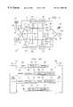
- FIG. 1is a high level block diagram of a network monitoring system coupled to a communication network
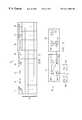
- FIG. 2is a block diagram of a network monitoring device
- FIG. 3Aillustrates a series of messages exchanged between end offices in a communications network
- FIG. 3Bis a block diagram illustrating messages exchanged over separate links in a communications network
- FIG. 4is a flow chart illustrating the movement of signaling units in a transaction processor of the present invention
- FIG. 5is a table used by the transaction processor shown in FIG. 4.
- FIG. 6is a simplified block diagram of the transaction processing system described herein.
- FIG. 1illustrates communications network 10 which may be a Signaling System Seven (SS7) network.
- Customers 101 and 102are coupled to end offices 103 and 104 via telephone lines 105 and 106 .
- End offices 103 and 104which may be Signaling Point (SPs) or Service Switching Points (SSPs), are coupled to STPs 107 - 110 via trunks 111 and 112 , which are known as A-links in an SS7 system.
- STPs 107 - 110are arranged in a mated pair configuration wherein C-Links, such as trunks 113 and 114 , link mated pairs 107 and 109 or 108 and 110 respectively.
- the mated pairsare linked via B-links, such as trunks 115 and 116 .
- SCP 117is coupled to STPs 107 and 109 via links 118 and 119 .
- SCP 117may be used in network 10 to provide database services for applications such as 800, CLASS, Local Number Portability (LNP).
- Calls and transactions between end offices 103 and 104are routed via STPs 107 - 110 via links 111 - 116 .
- Signaling units traveling between end office 103 and 104may take any number of paths through network 10 . Typically, signaling units traveling in one direction from end office 103 to 104 will follow the same path for one transaction or call. However, signaling units traveling in the opposite direction, from end office 104 to 103 , may take a different path for the same transaction or call.
- a Transaction Capabilities Application Part (TCAP) BEGIN messagemay be routed from end office 103 to end office 104 via STPs 107 and 108 across links 111 a , 115 , and 112 a .
- a TCAP response messagesuch as a CONTINUE or an END message, may be routed from end office 104 to end office 103 via STPs 110 and 109 across links 112 b , 116 , and 111 b .
- TCAPTransaction Capabilities Application Part
- network monitors 121 - 124capture substantially all of the signaling units traveling through network 10 .
- Each monitor, 121 - 124is non-intrusively coupled, via connections 125 - 128 , to all links associated with a particular STP 107 - 110 .
- monitor 121is associated with STP 107 and captures all messages traveling across links 113 , 115 , 118 and 119 .
- monitors 122 - 124monitor the messages passing through STPs 108 - 110 via links 126 - 128 .
- monitors 121 and 122both detect messages on link 115 .
- the other monitors, 123 and 124are not coupled to link 115 and, therefore, will not detect any of the messages on link 115 .
- Monitors 121 to 124are coupled to each other via inter-monitor communication bus 129 .
- Bus 129may be part of a data network, such as a Wide Area Network (WAN).
- Monitors 121 - 124may also be linked to a central server or user workstations, as disclosed in U.S. Pat. No. 6,249,572 and Ser. No. 09/094,123, now abandoned, the disclosure of which is hereby incorporated by reference herein.
- LDPsLink Distribution Processors
- IMCPInter-Monitor Communications Processor
- TPsTransaction Processors
- Distribution Manager (DM) 210controls the routing of signaling units between LDPs 201 - 204 , TPs 207 - 209 and IMCP 206 .
- IMCP 206is in communications with other monitors, such as monitors 122 and 123 as shown, via inter-monitor bus 129 .
- monitor 20is capable of processing circuit related messages and network management related messages in other processors (not shown).
- monitor 121is used as an example, it will be understood that other monitors in the network, such as 122 - 124 , operate in a similar manner.
- monitor 121receives signaling units from links 111 , 113 , 115 , and 118 via links 125 .
- LDPs 201 - 204receive the captured signaling units and route them to TPs 207 - 209 under the direction of DM 210 .
- FIG. 3Aillustrates a series of signaling units that are exchanged between end offices 301 and 302 for a particular transaction. Intermediate network elements, such as STPs, are not shown in FIG. 3 A. It will be understood that in a telecommunications network, such as in an SS7 network, messages may also be exchanged between other network components, such as between STPs and SCPs.
- the transaction in FIG. 3starts with BEGIN message 303 , which originates at end office 301 .
- the BEGIN message used herein, as well as the CONTINUE and END messages,is a generic message that is used to represent many types of SS7 transaction messages. For example, a BEGIN message may be a TCAP query, a CONTINUATION message may be a continue or conversation message, and an END message may be an abort or response message.
- BEGIN message 303is an initial message for a transaction.
- Message 303includes Transaction Identifier (TID) 304 .
- TIDTransaction Identifier
- end office 301will use TID 304 as the unique identifier for the transaction.
- Other concurrent transactionswill use be assigned a different TID.
- end office 301may reuse TID 304 .
- TID 304identifies the originating network element.
- TID 304is “A” or the identifier generated by end office 301 .
- Each TIDis an unique 32-bit number that is randomly generated by the initiating network element. The TID has significance for one series of messages representing one complete transaction.
- BEGIN message 303also has other components 305 , which vary depending upon the specific type of transaction.
- End office 302receives BEGIN message 303 and responds with CONTINUE message 306 .
- CONTINUE message 306comprises TID's 307 and 308 and message components 309 .
- TID 307represents the destination identifier, which in this case is “A” for end office 301 .
- Originating TID 308is “B” which has been assigned by end office 302 , the originating element for CONTINUE message 306 .
- end office 301responds to CONTINUE message 306 with CONTINUE message 310 , which also comprises destination and origination TIDs 311 and 312 and components 309 .
- Destination TIDis “B” for end office 302 and the originating TID is “A” for end office 301 .
- END message 314is sent by end office 302 at the completion of the transaction.
- Message 314comprises destination TID “A” and components 316 .
- END message 314does not need the originating TID “B” because this is the last message in the transaction and end office 301 will not respond to END message 314 .
- FIG. 3Billustrates how the BEGIN, CONTINUE and END messages may flow through communications network 10 .
- BEGIN message 303may pass through STPs 107 and 108 to end office 104 .
- end office 104initiates CONTINUE message 306 , which may traverse a different path through network 10 in route to end office 103 .
- CONTINUE message 306may pass through STPs 110 and 109 .
- network monitors 121 and 122will detect BEGIN message 303 and monitors 124 and 123 will detect CONTINUE message 306 .
- CONTINUE message 310also traverses through STPs 107 and 108 in route to end office 104 and END message 314 traverses STPs 110 and 109 .
- monitors 121 - 124will not detect the entire series of messages for this transaction.
- LDPs 202 and 204detect BEGIN message 303 and CONTINUE message 310 as these signaling units traverse links 111 and 115 . However, monitor 121 does not detect CONTINUE message 306 or END message 314 .
- BEGIN message 303starts in end office 103 and passes over A-link 111 where it is first detected by monitor 121 .
- LDP 202receives the signaling units from Link 111 . These signaling units are sent from LDP 202 to transaction processors 207 - 209 under the control of Distribution Manager 210 .
- DM 210continually monitors the processing load on TPs 207 - 209 and maintains track of which TIDs are assigned to each TP 207 - 209 .
- DM 210assigns the signaling unit to one of the TPs based upon the TP processing loads.
- One of the main keys to correlating messages in the present inventionis the designation of a specific transaction processor on a specific monitor as the controlling, or anchor, monitor for that transaction.
- the anchor monitor/transaction processortracks all signaling units for the assigned transactions.
- LDPs 201 to 204comprise a cache memory (not shown) which holds a table of TIDs mapped to assigned TPs. This table is continually updated. If LDPs 201 to 204 detect a signaling unit with a TID that has already been assigned, then that signaling unit will be sent to the appropriate TP. LDPs can directly route signaling units from LDP 201 to 204 to TPs 207 to 209 if LDPs 201 to 204 have a specific TID already stored locally in the cache. LDPs 201 - 204 first look to the local cache to determine whether the TID for a new signaling unit has been assigned to a specific TP.
- LDPs 201 to 204do not have that TID assigned locally, a query is sent to DM 210 requesting an assignment to a specific TP for the new TIED. LDPs 201 and 204 update the local cache tables when they receive instructions from DM 210 as to which TP the new signaling unit should be sent. Thereafter, future signaling units having that same TID will be sent directly from the LDP to the TP without having to query DM 210 .
- LDPs 201 - 204must select the correct TID to ensure that the message is sent to the correct TP for processing. For example, when monitor 121 receives BEGIN message 303 , LDP 202 will query DM 210 requesting an assignment for TID “A”. Once BEGIN message 303 is sent to a particular TP, such as 207 , for processing, then all later detected messages having the same TID “A” will be routed to the same TP, 207 .
- TPs 207 - 209receive signaling units from LDPs 201 - 204 , from other monitors via IMCP 206 and network 129 , or from other TPs 207 - 209 on monitor 121 .
- TPs 207 - 209have the capability of moving signaling units among the various processors in order to route the messages to the proper TP for a particular TID.
- TPs 207 - 209may also send signaling units to other monitoring units. Initially, system 20 may select the wrong TID and, as a result, route the signaling unit to the wrong TP for processing. Therefore, system 20 must allow TPs 207 - 209 to forward a mis-routed signaling unit to the proper TP.
- TID “A” 304is used to assign BEGIN message 303 to a TP, such as 207 , for processing.
- System 20uses the second TID in CONTINUE messages to route the messages to the proper TPs 207 - 209 .
- the second TIDis “B” 308 , which, if used for assigning message 306 to a TP, may cause message 306 to be routed the wrong TP, such as 208 instead of 207 .
- TPs 207 - 209have the capability to recognize when a message has been mis-routed and they can then re-route the message using the other TID in the message.
- TP 208would determine that CONTINUE message 306 has been mis-routed and it would forward CONTINUE message 306 to TP 207 using TID “A” 307 .
- IMCP 206follows a similar procedure for selecting which TID to use when assigning messages that are received via inter-monitor network 129 .
- IMCP 206also maintains a local cache comprising a table of TIDs mapped to specific assigned TPs. For TIDs that are not in the table on the IMCP cache, IMCP 206 queries DM 210 to determine which TP should receive the forwarded signaling unit.
- FIG. 4illustrates the logical operation of a transaction processor 40 , such as TP 207 .
- Signaling unitsmay be received from LDPs 401 or from other local TPs 402 , such as TPs 208 and 209 , via local bus 205 .
- TP 40may receive signaling units from other monitoring devices, such as monitors 122 - 124 .
- IMCP receiver 403receives signaling units that are forwarded from other monitors over network 129 . These signaling units are then routed via internal bus 205 to assigned TP 40 .
- Transaction Processor 40processes each signaling unit using an algorithm that is associated with the source of the signaling unit. Accordingly, signaling units that are received from LDPs 401 , local TPs 402 and IMCP 403 are all processed in a slightly different manner.
- TP 40sorts the signaling unit in sort queue 404 .
- Two criteriaare used in sort queue 404 .
- the signaling unitsare time sorted based upon a time stamp that is assigned to each signaling unit by the detecting LDP 201 - 204 .
- Each LDPtime stamps the captured signaling units before transmitting the signaling units to TPs 207 - 209 .
- Sort queue 404time sorts all of the received messages so that they are in order of time of detection. This compensates for delays on bus 205 and links 125 and ensures that TP 40 processes the signaling units in a chronological order.
- the second sort criteria for queue 404is inbound and outbound matching. As illustrated in FIG. 2, signaling units traveling from SP 103 to STP 108 will traverse links 111 and 115 . Accordingly, monitor 20 will detect the same signaling unit two times. LDP 202 will detect the signaling unit traversing link 111 and LDP 204 will detect the signaling unit as it traverses link 115 . Each time the signaling unit is detected, it receives a separate time stamp from LDPs 202 and 204 . TP 40 arranges the signal units in the proper time order and then matches inbound and outbound signaling units that correspond to one message.
- BEGIN message 303will be detected on link 111 and transmitted to a TP by LDP 202 .
- Message 303will also detected on link 115 by LDP 204 .
- TP 40determines that these are the same BEGIN messages, having the same TID “A” for originating SP 103 . Accordingly, these two detections of BEGIN message 303 are correlated in queue 404 into a single BEGIN message for processing. This prevents the messages from being processed twice within TP 40 .
- TP 40uses the TID and the originating and destination point codes of the messages for inbound/outbound matching. When the inbound and outbound messages are correlated, any changes that occur in the network node, such as Global Title Translation (GTT), are kept with the message. After sorting and matching the signaling units in queue 404 , TP 40 then processes each message at LDP decision point 405 .
- GTTGlobal Title Translation
- Transaction table 50 in FIG. 5is used to track each transaction signaling unit that is processed in TP 40 .
- Each transactionhas a unique TID and a point code. These parameters are used as the key or index 51 , 52 for transaction table 50 .
- Each entry 59 in table 50represents a separate transaction. The transactions are assigned variables 53 - 58 .
- the Type variable, 53is either long termed or short termed. Generally, signaling units corresponding to this transaction will be forwarded to another TP. Any transaction processor on a non-anchor monitor is always short termed. Any anchor transaction processor on an anchor monitor is always long term. A non-anchor transaction processor on an anchor monitor will eventually be promoted to long term by the anchor monitor so that messages will be forwarded to the anchor processor. The short term period is less than or equal to the period during which a TID cannot be reused. Long term transaction records are maintained until the transaction is complete, such as when an END message has been detected. In the preferred embodiment, users can configure the how long the short term transactions will be maintained in Table 50 . If no other message for a short term transaction is detected within the selected time period, then the transaction record is erased from Table 50 .
- transaction signaling unitsmay contain both an origination and destination TID. Additionally, the signaling units typically contain an origination point code (OPC) and/or a destination point code (DPC).
- OPCorigination point code
- DPCdestination point code
- transactions in table 50are keyed according to the origination point code 51 and originating TID 52 .
- the other point code 54such as the destination point code
- the other TID 55such as the destination TID are maintained in the transaction record for each signaling unit.
- Some messagessuch as END messages, do not have originating TIDs. These messages are keyed using the destination TID. It will be understood, with respect to Table 50 , that any point code or TID can be used either as a key or index parameter or as an alternate parameter.
- Processing instruction variable 56is used by TP 40 to determine whether signaling units for a transaction should be processed locally, or whether the messages should be sent to another processor.
- the Process Locally instructionis assigned for transactions that are assigned to this transaction processor 40 .
- TP 40is referred to as the anchor or controlling monitor for these transactions.
- the Process Locally instructionmay be assigned when TP 40 is responsible for the primary or secondary processing of a transaction, although it is not the anchor.
- the Forward Local TP instructionis used to route signaling units to another TP that is located on the same monitor.
- TP 207is the primary processor for a particular transaction
- TP 208when TP 208 detects signaling units for that transaction, TP 208 will forward the signaling unit to local TP 207 for processing.
- the Forward IMCP instructionis used to route signaling units to another TP on a remote monitor via network 129 which is the anchor or primary processor for a particular transaction.
- LDP decision point 405Signaling units are processed in LDP decision point 405 according to the message type. For example, BEGIN messages will be processed using a different algorithm than CONTINUE or END messages. BEGIN messages are received by LDPs 401 from the network links. LDPs 401 forward the BEGIN signaling units to a particular TP 40 as assigned by DM 210 . Typically, this assignment is based upon TP processing loads. The BEGIN message passes through sort queue 404 to LDP decision point 405 . TP 40 assumes that it has been assigned responsibility for processing transactions corresponding to the BEGIN message and creates an entry in Table 50 . Key point code 51 is the OPC and key TID 52 is the originating TID in the BEGIN message.
- Message type 53is set to long termed and processing instruction 56 is set to Process Locally since TP 40 is the controlling processor for any subsequent transaction messages having the same Key TID 52 .
- processing instruction 56is set to Process Locally since TP 40 is the controlling processor for any subsequent transaction messages having the same Key TID 52 .
- the BEGIN messageis sent from LDP decision point 405 to second sort queue 406 for further processing, which will be discussed below.
- CONTINUE messagesmay be assigned to TP 40 because TP 40 has been assigned as the controlling processor for that transaction.
- DM 210may assign the CONTINUE message and corresponding transaction to TP 40 based upon processor loading or other factors.
- LDP decision point 405initially uses the originating TID and originating OPC in the CONTINUE message to determine whether a corresponding entry exists on Table 50 .
- TP 40creates a record on Table 50 and configures the record by setting Key Point Code 51 to the OPC and by setting Key TID 52 to the originating TID.
- Type 53is set to short termed.
- Alternate Point Code 54 and Alternate TID 55are set to the DPC and destination TID, respectively.
- Instruction 56is set to Forward Local TP. The reason for using the Forward Local TP instruction is that this CONTINUE message was routed to TP 40 from LDPs 401 using the origination TID and, since no record currently existed, TP 40 was not already processing this transaction.
- TP 40Since DM 210 did not forward the CONTINUE message to IMPC 206 , TP 40 assumes that the CONTINUE message should be processed on the local monitor, but on a different TP. Accordingly, TP 40 forwards the CONTINUE message to another TP on the same monitor. However, when the CONTINUE message is forwarded in this situation, the alternative TID, here the destination TID, is used to route the CONTINUE message. TP 40 queries the DM 210 , using the alternative TID, to determine the appropriate transaction processor that should receive the CONTINUE message.
- TP 40will follow instructions 56 for that entry in Table 50 .
- the instructionsmay be Locally Process, in which case the CONTINUE message is forwarded to sort queue 406 to be processed locally at TP 40 .
- instructions 56may Forward Local TP or Forward IMCP, and TP 40 will forward the signaling unit to IMCP 407 or Local TP 408 . Since a message has been detected for an entry in Table 50 within the selected short term time period, the short termed timer is reset to zero since additional messages for that transaction may be detected.
- TP 40determines whether the DPC and destination TID are in Table 50 . If they are not found, TP 40 assumes that the proper instruction is Forward IMCP and the END message is forwarded to IMCP 407 . Additionally, a new record is created in Table 50 for the END message.
- the instruction 56 for this recordis an End Pending instruction, which will be discussed below.
- the recordis keyed 51 , 52 with the DPC and the destination TID and the type 53 is short termed. Therefore, the record will be deleted if no other message is detected for this transaction within the preconfigured time period. The END will be held by TP 40 and it will not be processed or forwarded until another message for the same transaction is detected.
- TP 40follows instructions 56 . If the instruction is Process Locally, then the end message is forwarded to sort queue 406 on TP 40 . Alternatively, the END message will be forwarded to IMCP 407 or to Local TP 408 as directed by instruction 56 .
- TP 40receives signaling units from other local TPs 402 and from IMCP 403 .
- IMCPs 403 and 407may be different devices or they be the same device, in which IMCP 403 represents a receive portion and IMCP 407 represents a transmit portion of the inter-monitor network interface.
- Signaling units or messages that are received by TP 40 from IMCP 403are processed using the logic in IMCP decision point 410 .
- BEGIN messageWhen a BEGIN message is received at IMCP decision point 410 , an error condition is created and the BEGIN message is ignored. This is because all BEGIN messages should be routed from an LDP directly to a local TP. Then the TP, as discussed above, creates a new record and processes the BEGIN transaction locally. Accordingly, BEGIN messages should not be forwarded from the TP that is initially assigned the message.
- TP 40looks to Table 50 using the OPC and origination TID. If a transaction record is found, then TP 40 follows the appropriate instructions 56 . If instruction 56 is Process Locally, TP 40 will forward the signaling unit to sort queue 406 . If instruction 56 is Forward Local TP, TP 40 will forward the CONTINUE message to a local TP 408 on the same monitoring unit.
- instruction 56is Forward IMCP, this creates an error condition at IMCP decision point 410 , because TP 40 has just received the CONTINUE message from IMCP 403 . Since the signaling unit has already traversed the IMCP, TP 40 will not forward the message back to IMCP 407 . As a result, the CONTINUE message will be ignored.
- TP 40assumes that the instruction for the CONTINUE message is Forward Local TP. Accordingly, TP 40 forwards the CONTINUE message to the appropriate local TP 408 . TP 40 also forwards the pending END message, which has been temporarily held as described above. This results in two messages being sent to local TP 408 , both the CONTINUE and the held up END message. The messages are forwarded using the DPC and destination TID of the CONTINUE message.
- IMCP decision point 410proceeds in the same manner as LDP decision point 405 for a CONTINUE message that is not found in Table 50 .
- TP 40creates a new record in Table 50 and sets Key Point Code 51 to the OPC and Key TID 52 to the origination TID. Record type 53 is set to short termed and Alternate Point Code 54 and Alternate TID 55 are set to the DCP and the destination TID, respectively. Instruction 56 is set to Forward Local TP. The CONTINUE message is then forwarded to local TP 408 from IMCP decision point 409 .
- TP 40looks-up the DPC and destination TID in Table 50 . If no corresponding record is found, then an error condition is created and TP 40 ignores the END message. On the other hand, if there is an entry for that point code and destination TID in Table 50 , then TP 40 follows instructions 56 . For a Process Locally instruction, TP 40 sends the END message to Sort Queue 406 , and for a Forward Local TP instruction, TP 40 sends the END message to Local TP 408 . However, if instruction 56 is Forward IMCP, this creates an error condition since the END message has already traversed network 129 .
- TP 40will not send a signaling unit back to IMCP 407 and network 129 a second time. Accordingly, the END is ignored.
- An End Pending instructionalso creates an error condition because there should only be a single END message for each transaction. An End Pending instruction indicates that there another END message already exists for that transaction, as a result the second END message is ignored.
- TP 40receives signaling units from other transaction processors on the same monitoring device. These signaling units are transferred among the TPs on local bus 205 . As these messages are received by TP 40 , they are processed at Local TP decision point 409 . BEGIN messages should not appear at Local TP decision point for the same reasons discussed above with respect to IMCP decision point 410 . Therefore, if a BEGIN message appears at Local TP decision point 409 , it will create an error condition and the BEGIN message will be ignored.
- TP 40When CONTINUE messages are received from Local TPs 402 , TP 40 does a look-up on Table 50 .
- the Table 50 look-upuses the alternate point code and TID, the DPC and the destination TID. These parameters are used because it is assumed that the other point code and TID, the OPC and originating TID, were used at Local TP 402 and not found as discussed above with respect to LDP decision point 405 and IMCP decision point 410 . Also, the CONTINUE message has been forwarded from Local TPs 402 using the DPC and the originating TID.
- TP 40determines whether the signaling unit has already traversed network 129 and IMCP 403 , 407 . An error condition is created if the CONTINUE message has already traversed IMCP 403 , 407 before being forwarded from Local TPs 402 and the CONTINUE message is ignored.
- the monitoring systemuses a tracking bit or bits on each signaling unit to indicate whether the signaling units have been passed via IMCP 206 or from Local TP 402 . This allows the transaction processors to determine where the signaling unit has been in the system.
- TP 40performs instructions 56 .
- Alternate Set 58is set to false initially. If instruction 56 is Process Locally, then TP 40 looks to Alternate Set 58 to determine whether it is set to true or false. If Alternate Set 58 is false, then a message will be sent to the forwarding TP, Local TP 402 , to change the forwarding TP's Alternate Set to true and Type to long termed. Alternate Set 58 on TP 40 's Table 50 is also set to true to indicate that the message has been sent to the forwarding TP. When Alternate Set is true, no message is sent to the forwarding TP. Alternate Set true indicates that the forwarding TP should use Alternate Point Code 54 and Alternate TID 55 to forward signaling units for that transaction record. Finally, the CONTINUE signaling unit is forwarded to sort queue 406 for local processing on TP 40 .
- Local TP decision point 409first determines whether the signaling unit has already traversed IMCP 407 and network 129 . If this signally unit has previously traversed IMCP 407 , then this creates an error condition and the message is ignored. On the other hand, if the message has not traversed IMCP 407 , then the CONTINUE message is forwarded to IMCP 407 to be routed to another TP on another monitor.
- instruction 56 for the CONTINUE messageis an End Pending instruction, then a look-up is done using the destination point code and TID for the message. If no record is found, then TP 40 determines whether the signaling unit has traversed IMCP 407 . If the CONTINUE message has not traversed network 129 or IMCP 403 , then it is forwarded to IMCP 407 . If the CONTINUE message has already traversed network 129 or IMCP 403 prior to Local TP 402 , then that creates an error condition and the signal unit is ignored.
- TP 40follows instruction 56 .
- a second End Pending instructioncreates an error condition and the signaling unit is ignored.
- instruction 56is Forward TP, this also creates an error condition and the CONTINUE message is ignored.
- TP 40again determines whether the message has traversed IMCP 403 , in which case there is an error condition and the signaling unit is ignored. Otherwise, the signaling unit is sent via IMCP 403 to another monitor. If instruction 56 it Process Locally, then the CONTINUE message is forwarded to sort queue 406 .
- FIG. 6is a simplified block diagram of a monitoring system 60 having monitors 61 and 62 .
- Monitor 61captures signaling units on link 63 between STPs 601 and 602 .
- link 63may be any link between any network elements, such as STPs, SCPs, SSPs, etc.
- Signaling units on trunk 63are detected by LDP 603 .
- a distribution manager(not shown) controls which transaction processor should receive the signaling unit from LDP 603 .
- the signaling unitis sent to TP 604 for processing.
- TP 604performs the operations discussed above for LDP decision point 405 .
- the signaling unitmay be processed locally on TP 604 , or may be forwarded either to TP 605 or IMCP 606 .
- indications processor 606indicates where it was forwarded to transaction processor 605 locally. That transaction processor then performs the steps discussed above with respect to decision point 409 , and either processes the signaling unit locally, or forwards it to inter-monitor communications processor 606 .
- TP 605If the signaling unit is sent to TP 605 , it is processed as described above with respect to Local TP decision point 409 . TP 605 can either process the signaling unit locally or forward it to IMCP 606 . TP 605 cannot forward the signaling unit to another TP in monitor 61 , since the message has already been forwarded locally once.
- Signaling units that are sent to IMCP 606are forwarded via an inter-monitor bus or data network, such as a WAN, to IMCP 607 on monitor 62 .
- a distribution manager on monitor 62(not shown) controls which TP 608 , 609 receives the signaling unit from IMCP 607 .
- TP 608receives a signaling unit from IMCP 607 , it performs the operations described above for IMCP decision point 410 .
- TP 608may process the signaling unit locally or it 608 may forward the signaling unit to another TP 609 on monitor 62 .
- TP 608cannot forward the signaling unit to IMCP 607 since this signaling unit has already traversed IMCP 607 once.
- the signaling unitis forwarded to TP 609 , it is processed as described above with respect to Local TP decision point 409 .
- the signaling unitsince the signaling unit has already traversed IMCP 607 and has already been transferred locally among TPs, the only option remaining for TP 609 is to process the signaling unit locally.
- the maximum number of transaction processors that can see the same signaling unitis four. This limit is set by the fact that a signaling unit can only be transferred once within a monitor, and can only be transferred once across the IMCP bus.
- a signaling unitwill be sent to a transaction processor 40 which will have the instruction Process Locally.
- the signaling units(BEGIN, CONTINUE, and END types) are sent to sort queue 406 .
- the end resultis that if one of the signaling units for a particular transaction goes into sort queue 406 , then all of the signaling units for that transaction are in sort queue 406 .
- the systemis configured so that all of the signaling units for one transaction all end up in the same sort queue 406 . Two signaling units for one transaction cannot be sent to two different sort queues 406 on two different transaction processors 40 .
- Sort queue 406performs a time sort of the signaling units that have been detected on various monitors. The monitors are synchronized and each signaling unit is time-stamped. Sort queue 406 compensates for the processing delays in the various monitors and transaction processors by sorting all of the signaling units into time order.
- State machine 411processes the signaling units for each transaction and creates a transaction record for each transaction.
- State machine 411is programmable and it can be driven based off of op codes, component types, time out conditions and other parameters.
- the state machinecan be designed to filter out and process certain types of transactions and data.
- State machine 411creates transaction records when ever a BEGIN message is detected.
- the signaling unit for the BEGIN messageis added to the transaction record.
- state machine 411finds the appropriate transaction record and adds the signaling unit for the CONTINUE message to the transaction record.
- state machine 411stores the END message signaling unit to the appropriate transaction record and then either stores the transaction record or deletes the transaction record depending upon the system's configuration and the applications that operate on the transaction record data. Then end of a transaction may be determined from an END message. In some cases, there may be a prearranged end instead of an END message, as in the case of an Integrated Network Application Part (INAP) transaction there is no END message.
- INAPIntegrated Network Application Part
- applicationscan access the transaction record data in real-time and process the transaction data based upon message type, component type, op codes, called number digits, calling number digits. Applications can be used to generate call detail records, to trace calls, or to generate network statistics.
- a separate state machine 411or other processor (not shown), is used for each application. Accordingly, it will be understood that additional state machines (not shown) may be coupled to sort queue 406 . Furthermore, sort queue 406 and state machine 411 may be coupled to a memory storage device for storing transaction records or application data.
Landscapes
- Engineering & Computer Science (AREA)
- Computer Networks & Wireless Communication (AREA)
- Signal Processing (AREA)
- Data Exchanges In Wide-Area Networks (AREA)
Abstract
Description
Claims (30)
Priority Applications (1)
| Application Number | Priority Date | Filing Date | Title |
|---|---|---|---|
| US09/092,771US6411604B1 (en) | 1998-06-05 | 1998-06-05 | System and method for correlating transaction messages in a communications network |
Applications Claiming Priority (1)
| Application Number | Priority Date | Filing Date | Title |
|---|---|---|---|
| US09/092,771US6411604B1 (en) | 1998-06-05 | 1998-06-05 | System and method for correlating transaction messages in a communications network |
Publications (1)
| Publication Number | Publication Date |
|---|---|
| US6411604B1true US6411604B1 (en) | 2002-06-25 |
Family
ID=22235084
Family Applications (1)
| Application Number | Title | Priority Date | Filing Date |
|---|---|---|---|
| US09/092,771Expired - LifetimeUS6411604B1 (en) | 1998-06-05 | 1998-06-05 | System and method for correlating transaction messages in a communications network |
Country Status (1)
| Country | Link |
|---|---|
| US (1) | US6411604B1 (en) |
Cited By (16)
| Publication number | Priority date | Publication date | Assignee | Title |
|---|---|---|---|---|
| US20010026612A1 (en)* | 2000-03-10 | 2001-10-04 | Gabriele Duspiva | Method for providing a service in a telecommunication network and a corresponding infrastructure manager |
| US20010055278A1 (en)* | 2000-06-21 | 2001-12-27 | Hiroshi Ooiwane | Communication control method and apparatus in intelligent network |
| US6529594B1 (en)* | 1998-06-05 | 2003-03-04 | Inet Technologies, Inc. | System and method for generating quality of service statistics for an international communications network |
| US6614894B1 (en) | 1998-06-05 | 2003-09-02 | Inet Technologies, Inc. | System and method for mass call onset detection in a communications network |
| US20040228469A1 (en)* | 2003-05-12 | 2004-11-18 | Wayne Andrews | Universal state-aware communications |
| US6891938B1 (en)* | 2000-11-07 | 2005-05-10 | Agilent Technologies, Inc. | Correlation and enrichment of telephone system call data records |
| US20050265341A1 (en)* | 1998-12-04 | 2005-12-01 | Tekelec | Methods and systems for communicating SS7 messages over packet-based network using transport adapter layer interface |
| US20060251235A1 (en)* | 2005-05-09 | 2006-11-09 | Samsung Electronics Co., Ltd. | Advanced intelligent network access manager with state machine for processing multiple TCAP component messages |
| US7170989B1 (en)* | 2002-09-06 | 2007-01-30 | Sprint Communications Company L.P. | Transaction dependency manager |
| US20080181378A1 (en)* | 2007-01-30 | 2008-07-31 | Lucent Technologies Inc. | Method of correlating charging data records within an offline charging system |
| US20080247390A1 (en)* | 2007-04-06 | 2008-10-09 | Research In Motion Limited | System and method for correlating messages within a wireless transaction |
| US7522580B2 (en) | 1998-12-04 | 2009-04-21 | Tekelec | Edge device and method for interconnecting SS7 signaling points (SPs) using edge device |
| US7532647B2 (en) | 2004-07-14 | 2009-05-12 | Tekelec | Methods and systems for auto-correlating message transfer part (MTP) priority and internet protocol (IP) type of service in converged networks |
| US7743131B2 (en) | 2000-06-01 | 2010-06-22 | Tekelec | Methods and systems for managing status audit messages in a gateway routing node |
| US7839889B2 (en) | 1998-12-04 | 2010-11-23 | Tekelec | Methods and systems for communicating signaling system 7 (SS7) user part messages among SS7 signaling points (SPs) and internet protocol (IP) nodes using signal transfer points (STPs) |
| WO2012106573A1 (en)* | 2011-02-04 | 2012-08-09 | Opnet Technologies, Inc. | Correlating input and output requests between client and server components in a multi-tier application |
Citations (81)
| Publication number | Priority date | Publication date | Assignee | Title |
|---|---|---|---|---|
| US5008929A (en) | 1990-01-18 | 1991-04-16 | U.S. Intelco Networks, Inc. | Billing system for telephone signaling network |
| EP0541145A1 (en) | 1991-10-21 | 1993-05-12 | Koninklijke KPN N.V. | Monitoring system for monitoring a telecommunication network containing one or more subscriber exchanges |
| US5218632A (en) | 1991-10-16 | 1993-06-08 | Telefonaktiebolaget L M Ericsson | Flexible call detail recording system |
| US5333183A (en) | 1992-03-13 | 1994-07-26 | Moscom Corporation | Universal MDR data record collection and reporting system |
| US5426688A (en) | 1993-05-12 | 1995-06-20 | Anand; Vivodh Z. J. | Telecommunication alarm method and system |
| US5438570A (en) | 1993-12-29 | 1995-08-01 | Tekno Industries, Inc. | Service observing equipment for signalling System Seven telephone network |
| US5448624A (en) | 1990-08-22 | 1995-09-05 | Mci Communications Corporation | Telephone network performance monitoring method and system |
| US5457729A (en) | 1993-03-15 | 1995-10-10 | Symmetricom, Inc. | Communication network signalling system link monitor and test unit |
| US5473596A (en) | 1993-12-09 | 1995-12-05 | At&T Corp. | Method and system for monitoring telecommunication network element alarms |
| WO1995033352A2 (en) | 1994-06-01 | 1995-12-07 | Ericsson A/S | A system for monitoring telephone networks and/or data communication networks, especially mobile telephone networks |
| US5475732A (en) | 1993-02-16 | 1995-12-12 | C & P Of Virginia | Common channeling signaling network maintenance and testing |
| US5488648A (en) | 1993-08-17 | 1996-01-30 | Telefonaktiebolaget L M Ericsson | Behavior monitoring and analyzing system for stored program controlled switching system |
| US5521902A (en) | 1993-12-06 | 1996-05-28 | Hewlett-Packard Company | Location identification in a communications signalling network |
| US5539804A (en) | 1994-02-25 | 1996-07-23 | Ctel Compression Telecommunications Corporation | Common channel signalling communication monitoring system |
| US5550984A (en) | 1994-12-07 | 1996-08-27 | Matsushita Electric Corporation Of America | Security system for preventing unauthorized communications between networks by translating communications received in ip protocol to non-ip protocol to remove address and routing services information |
| US5550914A (en) | 1994-02-25 | 1996-08-27 | Clarke; David A. | Communications signalling network apparatus |
| US5579371A (en) | 1994-11-22 | 1996-11-26 | Unisys Corporation | Common channel signaling network applications platform |
| US5590171A (en) | 1994-07-07 | 1996-12-31 | Bellsouth Corporation | Method and apparatus for communications monitoring |
| US5592530A (en) | 1995-01-25 | 1997-01-07 | Inet, Inc. | Telephone switch dual monitors |
| WO1997005749A2 (en) | 1995-07-21 | 1997-02-13 | Call Manage Ltd. | Telecommunications call management system |
| US5627886A (en) | 1994-09-22 | 1997-05-06 | Electronic Data Systems Corporation | System and method for detecting fraudulent network usage patterns using real-time network monitoring |
| WO1997016916A1 (en) | 1995-11-01 | 1997-05-09 | Telecom Internet Ltd. | Method and apparatus for implementing a computer network/internet telephone system |
| WO1997022212A1 (en) | 1995-12-11 | 1997-06-19 | Hewlett-Packard Company | Method of accessing service resource items that are for use in a telecommunications system |
| US5642396A (en) | 1995-05-10 | 1997-06-24 | Mci Corporation | Release cause table for failed calls in SS7/ISDN Networks |
| WO1997023078A1 (en) | 1995-12-20 | 1997-06-26 | Mci Communications Corporation | Hybrid packet-switched and circuit-switched telephony system |
| US5659542A (en) | 1995-03-03 | 1997-08-19 | Intecom, Inc. | System and method for signalling and call processing for private and hybrid communications systems including multimedia systems |
| US5675635A (en) | 1996-01-24 | 1997-10-07 | Sprint Communications Company L.P. | System and method for conducting poll at a processor associated with the originating switch |
| WO1997038551A2 (en) | 1996-04-04 | 1997-10-16 | Dsc Telecom L.P. | Method and apparatus for routing internet calls |
| US5680437A (en) | 1996-06-04 | 1997-10-21 | Motorola, Inc. | Signaling system seven distributed call terminating processor |
| US5680442A (en) | 1994-12-05 | 1997-10-21 | Bell Atlantic Network Services, Inc. | Voice mail communication with call blocking |
| US5694451A (en) | 1991-11-27 | 1997-12-02 | Televerket | Method and an arrangement for performance monitoring in a telecommunications network |
| US5699412A (en) | 1995-09-18 | 1997-12-16 | Intervoice Limited Partnership | Systems and methods for statistical distribution of messages in a message recording system |
| US5699348A (en) | 1995-10-31 | 1997-12-16 | Lucent Technologies Inc. | Method and apparatus for error performance monitoring of a leased telecommunication circuit |
| US5703939A (en) | 1995-07-27 | 1997-12-30 | Lucent Technologies, Inc. | Method for determining an optimum point for database queries during call delivery in a telecommunications network |
| US5706286A (en) | 1995-04-19 | 1998-01-06 | Mci Communications Corporation | SS7 gateway |
| US5712908A (en) | 1995-12-22 | 1998-01-27 | Unisys Corporation | Apparatus and method for generating call duration billing records utilizing ISUP messages in the CCS/SS7 telecommunications network |
| US5715293A (en) | 1996-05-28 | 1998-02-03 | Mahoney; Michael Lawrence | Method and apparatus for monitoring telecommunication signals |
| US5719930A (en) | 1996-07-08 | 1998-02-17 | Bell Canada | Method of volume screening signalling messages in a telecommunication system |
| US5729597A (en) | 1995-05-16 | 1998-03-17 | At&T Corp | Service and information management system for a telecommunications network |
| US5737399A (en) | 1995-07-13 | 1998-04-07 | Mci Communications Corporation | Network information architecture having centralizing storage and verification element |
| US5737332A (en) | 1996-01-31 | 1998-04-07 | Motorola, Inc. | Data link control method |
| EP0841832A2 (en) | 1996-11-08 | 1998-05-13 | AT&T Corp. | Promiscuous network monitoring utilizing multicasting within a switch |
| US5757895A (en) | 1995-11-09 | 1998-05-26 | Unisys Corporation | Extracting and processing data derived from a common channel signalling network |
| US5771274A (en) | 1996-06-21 | 1998-06-23 | Mci Communications Corporation | Topology-based fault analysis in telecommunications networks |
| WO1998028879A1 (en) | 1996-12-20 | 1998-07-02 | Ericsson Inc. | Network manager providing advanced interconnection capability |
| US5793771A (en) | 1996-06-27 | 1998-08-11 | Mci Communications Corporation | Communication gateway |
| US5799073A (en) | 1995-06-07 | 1998-08-25 | Southwestern Bell Technology Resources, Inc. | Apparatus and method for recording call related data |
| US5802303A (en) | 1994-08-03 | 1998-09-01 | Hitachi, Ltd. | Monitor data collecting method for parallel computer system |
| US5815559A (en) | 1995-04-21 | 1998-09-29 | Lucent Technologies Inc. | Method for selecting AMA records using directory numbers |
| US5822401A (en) | 1995-11-02 | 1998-10-13 | Intervoice Limited Partnership | Statistical diagnosis in interactive voice response telephone system |
| US5825769A (en) | 1995-03-17 | 1998-10-20 | Mci Corporation | System and method therefor of viewing in real time call traffic of a telecommunications network |
| WO1998047298A2 (en) | 1997-04-15 | 1998-10-22 | Mci Worldcom, Inc. | A system, method and article of manufacture for switched telephony communication |
| WO1998047275A2 (en) | 1997-04-16 | 1998-10-22 | Alcatel Usa Sourcing, L.P. | Signaling network gateway |
| US5828729A (en) | 1995-11-22 | 1998-10-27 | Stentor Resource Centre Inc. | Automated mass calling detection using CCS7 message parameters |
| US5832068A (en) | 1994-06-01 | 1998-11-03 | Davox Corporation | Data processing system with real time priority updating of data records and dynamic record exclusion |
| US5854824A (en) | 1994-09-04 | 1998-12-29 | Rit Technologies Ltd. | Connectivity scanner |
| US5854835A (en) | 1996-02-09 | 1998-12-29 | Bell Atlantic Network Services, Inc. | Telecommunications network circuit usage measurement |
| US5867558A (en) | 1995-12-12 | 1999-02-02 | At&T Corp. | Method for remote collection of signaling messages for routing analysis and trouble detection |
| US5870565A (en) | 1996-05-06 | 1999-02-09 | Telefonaktiebolaget L M Ericsson (Publ) | Telecommunications management network connected to a common channel signaling network |
| US5875238A (en) | 1995-12-21 | 1999-02-23 | Ericsson Inc. | Transport mechanism for accounting messages within a telecommunications system |
| WO1999009705A2 (en) | 1997-08-13 | 1999-02-25 | Koninklijke Philips Electronics N.V. | Method and system for a two-step dialing connection process providing an identification of a second terminal via the internet |
| US5881132A (en) | 1997-06-27 | 1999-03-09 | Bell Canada | Method and apparatus for monitoring selected telecommunications sessions in an intelligent switched telephone network |
| US5883948A (en) | 1995-06-19 | 1999-03-16 | Lucent Technologies Inc. | Method for automatic maintenance of a local number portability database |
| EP0905565A1 (en) | 1997-09-30 | 1999-03-31 | Siemens Aktiengesellschaft | Improved deep ultraviolet photolithography |
| US5896292A (en) | 1995-06-05 | 1999-04-20 | Canon Kabushiki Kaisha | Automated system for production facility |
| US5898667A (en)* | 1996-12-31 | 1999-04-27 | Northern Telecom Limited | SS7 network management primeship |
| US5912954A (en) | 1997-02-28 | 1999-06-15 | Alcatel Usa Sourcing, L.P. | Method and system for providing billing information in a telecommunications network |
| US5920613A (en) | 1997-04-25 | 1999-07-06 | Ameritech Corporation | Method and system for generating a billing record |
| US5920257A (en) | 1997-07-31 | 1999-07-06 | Mci Communications Corporation | System and method for isolating an outage within a communications network |
| US5937345A (en) | 1997-05-02 | 1999-08-10 | Nortel Networks Corporation | Method and apparatus for intercepting calls in a communications system |
| US5999179A (en) | 1997-11-17 | 1999-12-07 | Fujitsu Limited | Platform independent computer network management client |
| US5999604A (en) | 1998-03-03 | 1999-12-07 | Mci Communications Corporation | System and method for managing a telecommunications network by determining service impact |
| US6021117A (en) | 1996-03-04 | 2000-02-01 | Madge Networks (Israel) Ltd. | System for parameter analysis and traffic monitoring in asynchronous transfer mode (ATM) networks |
| US6028914A (en) | 1998-04-09 | 2000-02-22 | Inet Technologies, Inc. | System and method for monitoring performance statistics in a communications network |
| US6041352A (en) | 1998-01-23 | 2000-03-21 | Hewlett-Packard Company | Response time measuring system and method for determining and isolating time delays within a network |
| US6072797A (en)* | 1997-07-31 | 2000-06-06 | International Business Machines Corporation | Methods, apparatus and computer program products for aggregated transmission groups in high speed networks |
| US6078647A (en) | 1997-11-21 | 2000-06-20 | Hewlett Packard Company | Method and apparatus for detecting a data service provider in a public switched telephone network |
| US6112083A (en) | 1996-03-27 | 2000-08-29 | Amsc Subsidiary Corporation | Full service dispatcher for satellite trunked radio service system |
| US6118936A (en)* | 1996-04-18 | 2000-09-12 | Mci Communications Corporation | Signaling network management system for converting network events into standard form and then correlating the standard form events with topology and maintenance information |
| US6249572B1 (en) | 1998-06-08 | 2001-06-19 | Inet Technologies, Inc. | Transaction control application part (TCAP) call detail record generation in a communications network |
| US6253266B1 (en) | 1999-02-19 | 2001-06-26 | Inet Technologies, Inc. | Apparatus and method for controlling information flow in a card cage having multiple backplanes |
- 1998
- 1998-06-05USUS09/092,771patent/US6411604B1/ennot_activeExpired - Lifetime
Patent Citations (82)
| Publication number | Priority date | Publication date | Assignee | Title |
|---|---|---|---|---|
| US5008929A (en) | 1990-01-18 | 1991-04-16 | U.S. Intelco Networks, Inc. | Billing system for telephone signaling network |
| US5448624A (en) | 1990-08-22 | 1995-09-05 | Mci Communications Corporation | Telephone network performance monitoring method and system |
| US5218632A (en) | 1991-10-16 | 1993-06-08 | Telefonaktiebolaget L M Ericsson | Flexible call detail recording system |
| EP0541145A1 (en) | 1991-10-21 | 1993-05-12 | Koninklijke KPN N.V. | Monitoring system for monitoring a telecommunication network containing one or more subscriber exchanges |
| US5694451A (en) | 1991-11-27 | 1997-12-02 | Televerket | Method and an arrangement for performance monitoring in a telecommunications network |
| US5333183A (en) | 1992-03-13 | 1994-07-26 | Moscom Corporation | Universal MDR data record collection and reporting system |
| US5892812A (en)* | 1993-02-16 | 1999-04-06 | C & P Of Virginia | Common channeling signaling network maintenance and testing |
| US5475732A (en) | 1993-02-16 | 1995-12-12 | C & P Of Virginia | Common channeling signaling network maintenance and testing |
| US5457729A (en) | 1993-03-15 | 1995-10-10 | Symmetricom, Inc. | Communication network signalling system link monitor and test unit |
| US5426688A (en) | 1993-05-12 | 1995-06-20 | Anand; Vivodh Z. J. | Telecommunication alarm method and system |
| US5488648A (en) | 1993-08-17 | 1996-01-30 | Telefonaktiebolaget L M Ericsson | Behavior monitoring and analyzing system for stored program controlled switching system |
| US5521902A (en) | 1993-12-06 | 1996-05-28 | Hewlett-Packard Company | Location identification in a communications signalling network |
| US5473596A (en) | 1993-12-09 | 1995-12-05 | At&T Corp. | Method and system for monitoring telecommunication network element alarms |
| US5438570A (en) | 1993-12-29 | 1995-08-01 | Tekno Industries, Inc. | Service observing equipment for signalling System Seven telephone network |
| US5539804A (en) | 1994-02-25 | 1996-07-23 | Ctel Compression Telecommunications Corporation | Common channel signalling communication monitoring system |
| US5550914A (en) | 1994-02-25 | 1996-08-27 | Clarke; David A. | Communications signalling network apparatus |
| WO1995033352A2 (en) | 1994-06-01 | 1995-12-07 | Ericsson A/S | A system for monitoring telephone networks and/or data communication networks, especially mobile telephone networks |
| US5832068A (en) | 1994-06-01 | 1998-11-03 | Davox Corporation | Data processing system with real time priority updating of data records and dynamic record exclusion |
| US5590171A (en) | 1994-07-07 | 1996-12-31 | Bellsouth Corporation | Method and apparatus for communications monitoring |
| US5802303A (en) | 1994-08-03 | 1998-09-01 | Hitachi, Ltd. | Monitor data collecting method for parallel computer system |
| US5854824A (en) | 1994-09-04 | 1998-12-29 | Rit Technologies Ltd. | Connectivity scanner |
| US5627886A (en) | 1994-09-22 | 1997-05-06 | Electronic Data Systems Corporation | System and method for detecting fraudulent network usage patterns using real-time network monitoring |
| US5579371A (en) | 1994-11-22 | 1996-11-26 | Unisys Corporation | Common channel signaling network applications platform |
| US5680442A (en) | 1994-12-05 | 1997-10-21 | Bell Atlantic Network Services, Inc. | Voice mail communication with call blocking |
| US5550984A (en) | 1994-12-07 | 1996-08-27 | Matsushita Electric Corporation Of America | Security system for preventing unauthorized communications between networks by translating communications received in ip protocol to non-ip protocol to remove address and routing services information |
| US5592530A (en) | 1995-01-25 | 1997-01-07 | Inet, Inc. | Telephone switch dual monitors |
| US5659542A (en) | 1995-03-03 | 1997-08-19 | Intecom, Inc. | System and method for signalling and call processing for private and hybrid communications systems including multimedia systems |
| US5825769A (en) | 1995-03-17 | 1998-10-20 | Mci Corporation | System and method therefor of viewing in real time call traffic of a telecommunications network |
| US5706286A (en) | 1995-04-19 | 1998-01-06 | Mci Communications Corporation | SS7 gateway |
| US5815559A (en) | 1995-04-21 | 1998-09-29 | Lucent Technologies Inc. | Method for selecting AMA records using directory numbers |
| US5642396A (en) | 1995-05-10 | 1997-06-24 | Mci Corporation | Release cause table for failed calls in SS7/ISDN Networks |
| US5729597A (en) | 1995-05-16 | 1998-03-17 | At&T Corp | Service and information management system for a telecommunications network |
| US5896292A (en) | 1995-06-05 | 1999-04-20 | Canon Kabushiki Kaisha | Automated system for production facility |
| US5799073A (en) | 1995-06-07 | 1998-08-25 | Southwestern Bell Technology Resources, Inc. | Apparatus and method for recording call related data |
| US5883948A (en) | 1995-06-19 | 1999-03-16 | Lucent Technologies Inc. | Method for automatic maintenance of a local number portability database |
| US5737399A (en) | 1995-07-13 | 1998-04-07 | Mci Communications Corporation | Network information architecture having centralizing storage and verification element |
| WO1997005749A2 (en) | 1995-07-21 | 1997-02-13 | Call Manage Ltd. | Telecommunications call management system |
| US5703939A (en) | 1995-07-27 | 1997-12-30 | Lucent Technologies, Inc. | Method for determining an optimum point for database queries during call delivery in a telecommunications network |
| US5699412A (en) | 1995-09-18 | 1997-12-16 | Intervoice Limited Partnership | Systems and methods for statistical distribution of messages in a message recording system |
| US5699348A (en) | 1995-10-31 | 1997-12-16 | Lucent Technologies Inc. | Method and apparatus for error performance monitoring of a leased telecommunication circuit |
| WO1997016916A1 (en) | 1995-11-01 | 1997-05-09 | Telecom Internet Ltd. | Method and apparatus for implementing a computer network/internet telephone system |
| US5822401A (en) | 1995-11-02 | 1998-10-13 | Intervoice Limited Partnership | Statistical diagnosis in interactive voice response telephone system |
| US5757895A (en) | 1995-11-09 | 1998-05-26 | Unisys Corporation | Extracting and processing data derived from a common channel signalling network |
| US5828729A (en) | 1995-11-22 | 1998-10-27 | Stentor Resource Centre Inc. | Automated mass calling detection using CCS7 message parameters |
| WO1997022212A1 (en) | 1995-12-11 | 1997-06-19 | Hewlett-Packard Company | Method of accessing service resource items that are for use in a telecommunications system |
| US5867558A (en) | 1995-12-12 | 1999-02-02 | At&T Corp. | Method for remote collection of signaling messages for routing analysis and trouble detection |
| WO1997023078A1 (en) | 1995-12-20 | 1997-06-26 | Mci Communications Corporation | Hybrid packet-switched and circuit-switched telephony system |
| US5875238A (en) | 1995-12-21 | 1999-02-23 | Ericsson Inc. | Transport mechanism for accounting messages within a telecommunications system |
| US5712908A (en) | 1995-12-22 | 1998-01-27 | Unisys Corporation | Apparatus and method for generating call duration billing records utilizing ISUP messages in the CCS/SS7 telecommunications network |
| US5675635A (en) | 1996-01-24 | 1997-10-07 | Sprint Communications Company L.P. | System and method for conducting poll at a processor associated with the originating switch |
| US5737332A (en) | 1996-01-31 | 1998-04-07 | Motorola, Inc. | Data link control method |
| US5854835A (en) | 1996-02-09 | 1998-12-29 | Bell Atlantic Network Services, Inc. | Telecommunications network circuit usage measurement |
| US6021117A (en) | 1996-03-04 | 2000-02-01 | Madge Networks (Israel) Ltd. | System for parameter analysis and traffic monitoring in asynchronous transfer mode (ATM) networks |
| US6112083A (en) | 1996-03-27 | 2000-08-29 | Amsc Subsidiary Corporation | Full service dispatcher for satellite trunked radio service system |
| WO1997038551A2 (en) | 1996-04-04 | 1997-10-16 | Dsc Telecom L.P. | Method and apparatus for routing internet calls |
| US6118936A (en)* | 1996-04-18 | 2000-09-12 | Mci Communications Corporation | Signaling network management system for converting network events into standard form and then correlating the standard form events with topology and maintenance information |
| US5870565A (en) | 1996-05-06 | 1999-02-09 | Telefonaktiebolaget L M Ericsson (Publ) | Telecommunications management network connected to a common channel signaling network |
| US5715293A (en) | 1996-05-28 | 1998-02-03 | Mahoney; Michael Lawrence | Method and apparatus for monitoring telecommunication signals |
| US5680437A (en) | 1996-06-04 | 1997-10-21 | Motorola, Inc. | Signaling system seven distributed call terminating processor |
| US5771274A (en) | 1996-06-21 | 1998-06-23 | Mci Communications Corporation | Topology-based fault analysis in telecommunications networks |
| US5793771A (en) | 1996-06-27 | 1998-08-11 | Mci Communications Corporation | Communication gateway |
| US5719930A (en) | 1996-07-08 | 1998-02-17 | Bell Canada | Method of volume screening signalling messages in a telecommunication system |
| EP0841832A2 (en) | 1996-11-08 | 1998-05-13 | AT&T Corp. | Promiscuous network monitoring utilizing multicasting within a switch |
| WO1998028879A1 (en) | 1996-12-20 | 1998-07-02 | Ericsson Inc. | Network manager providing advanced interconnection capability |
| US5898667A (en)* | 1996-12-31 | 1999-04-27 | Northern Telecom Limited | SS7 network management primeship |
| US5912954A (en) | 1997-02-28 | 1999-06-15 | Alcatel Usa Sourcing, L.P. | Method and system for providing billing information in a telecommunications network |
| WO1998047298A2 (en) | 1997-04-15 | 1998-10-22 | Mci Worldcom, Inc. | A system, method and article of manufacture for switched telephony communication |
| WO1998047275A2 (en) | 1997-04-16 | 1998-10-22 | Alcatel Usa Sourcing, L.P. | Signaling network gateway |
| US5920613A (en) | 1997-04-25 | 1999-07-06 | Ameritech Corporation | Method and system for generating a billing record |
| US5937345A (en) | 1997-05-02 | 1999-08-10 | Nortel Networks Corporation | Method and apparatus for intercepting calls in a communications system |
| US5881132A (en) | 1997-06-27 | 1999-03-09 | Bell Canada | Method and apparatus for monitoring selected telecommunications sessions in an intelligent switched telephone network |
| US5920257A (en) | 1997-07-31 | 1999-07-06 | Mci Communications Corporation | System and method for isolating an outage within a communications network |
| US6072797A (en)* | 1997-07-31 | 2000-06-06 | International Business Machines Corporation | Methods, apparatus and computer program products for aggregated transmission groups in high speed networks |
| WO1999009705A2 (en) | 1997-08-13 | 1999-02-25 | Koninklijke Philips Electronics N.V. | Method and system for a two-step dialing connection process providing an identification of a second terminal via the internet |
| EP0905565A1 (en) | 1997-09-30 | 1999-03-31 | Siemens Aktiengesellschaft | Improved deep ultraviolet photolithography |
| US5999179A (en) | 1997-11-17 | 1999-12-07 | Fujitsu Limited | Platform independent computer network management client |
| US6078647A (en) | 1997-11-21 | 2000-06-20 | Hewlett Packard Company | Method and apparatus for detecting a data service provider in a public switched telephone network |
| US6041352A (en) | 1998-01-23 | 2000-03-21 | Hewlett-Packard Company | Response time measuring system and method for determining and isolating time delays within a network |
| US5999604A (en) | 1998-03-03 | 1999-12-07 | Mci Communications Corporation | System and method for managing a telecommunications network by determining service impact |
| US6028914A (en) | 1998-04-09 | 2000-02-22 | Inet Technologies, Inc. | System and method for monitoring performance statistics in a communications network |
| US6249572B1 (en) | 1998-06-08 | 2001-06-19 | Inet Technologies, Inc. | Transaction control application part (TCAP) call detail record generation in a communications network |
| US6253266B1 (en) | 1999-02-19 | 2001-06-26 | Inet Technologies, Inc. | Apparatus and method for controlling information flow in a card cage having multiple backplanes |
Non-Patent Citations (8)
| Title |
|---|
| Geiger, Robert L. et al., "Wireless Network Extension Using Mobile IP," XP000628459, Motorola, Inc. Feb. 25, 1996, pp 9-14. |
| IEEE Standard Core Specs for Microcomputers-Jun. 18, 1992. |
| IEEE Standard for Metric Equipment Jan. 9, 1992. |
| Intelligent Remote Monitoring Oct. 16, 1995. |
| Schoen U. et al. "Convergence Between Public Switching and The Internet", ISS World Telecommunications Congress, CA, Toronto, Pinnacle Group, Sep. 21, 1997, pp. 549-560. |
| U.S. patent application Ser. No. 09/092,256, "System and Method for Generating Quality of Service Statistics for an International Communications Network", Jun. 5, 1998. |
| U.S. patent application Ser. No. 09/092,428, "System and Method for Detecting High Message Traffic Levels in a Communications Network", Jun. 5, 1998. |
| U.S. patent application Ser. No. 09/092,699, "System and Method for Signal Unit Data Storage and Post Capture Cell Trace in a Communications Network", Jun. 5, 1998. |
Cited By (29)
| Publication number | Priority date | Publication date | Assignee | Title |
|---|---|---|---|---|
| US7564870B2 (en) | 1997-07-02 | 2009-07-21 | Tekelec | Methods and systems for providing database node access control functionality in a communications network routing node |
| US6614894B1 (en) | 1998-06-05 | 2003-09-02 | Inet Technologies, Inc. | System and method for mass call onset detection in a communications network |
| US6529594B1 (en)* | 1998-06-05 | 2003-03-04 | Inet Technologies, Inc. | System and method for generating quality of service statistics for an international communications network |
| US7525997B2 (en) | 1998-12-04 | 2009-04-28 | Tekelec | Methods and systems for communicating SS7 messages over packet-based network using transport adapter layer interface |
| US7573905B2 (en) | 1998-12-04 | 2009-08-11 | Tekelec | Methods and systems for communicating SS7 messages over packet-based network using transport adapter layer interface (TALI) |
| US8750328B2 (en) | 1998-12-04 | 2014-06-10 | Tekelec Global, Inc. | Methods and systems for communicating signaling system 7 (SS7) user part messages among SS7 signaling points (SPs) and internet protocol (IP) nodes using signal transfer points (STPs) |
| US20050265341A1 (en)* | 1998-12-04 | 2005-12-01 | Tekelec | Methods and systems for communicating SS7 messages over packet-based network using transport adapter layer interface |
| US20050286502A1 (en)* | 1998-12-04 | 2005-12-29 | Tekelec | Methods and systems for communicating SS7 messages over packet-based network using transport adapter layer interface |
| US8213410B2 (en) | 1998-12-04 | 2012-07-03 | Tekelec, Inc. | Methods and systems for communicating SS7 messages over packet-based network using transport adapter layer interface |
| US7839889B2 (en) | 1998-12-04 | 2010-11-23 | Tekelec | Methods and systems for communicating signaling system 7 (SS7) user part messages among SS7 signaling points (SPs) and internet protocol (IP) nodes using signal transfer points (STPs) |
| US7522580B2 (en) | 1998-12-04 | 2009-04-21 | Tekelec | Edge device and method for interconnecting SS7 signaling points (SPs) using edge device |
| US7616659B2 (en)* | 1998-12-04 | 2009-11-10 | Tekelec | Methods and systems for communicating SS7 messages over packet-based network using transport adapter layer interface |
| US6954523B2 (en)* | 2000-03-10 | 2005-10-11 | Alcatel | Method for providing a service in a telecommunication network and a corresponding infrastructure manager |
| US20010026612A1 (en)* | 2000-03-10 | 2001-10-04 | Gabriele Duspiva | Method for providing a service in a telecommunication network and a corresponding infrastructure manager |
| US8224928B2 (en) | 2000-06-01 | 2012-07-17 | Tekelec, Inc. | Methods and systems for distributing operating status information within a converged network |
| US7743131B2 (en) | 2000-06-01 | 2010-06-22 | Tekelec | Methods and systems for managing status audit messages in a gateway routing node |
| US20010055278A1 (en)* | 2000-06-21 | 2001-12-27 | Hiroshi Ooiwane | Communication control method and apparatus in intelligent network |
| US6891938B1 (en)* | 2000-11-07 | 2005-05-10 | Agilent Technologies, Inc. | Correlation and enrichment of telephone system call data records |
| US7170989B1 (en)* | 2002-09-06 | 2007-01-30 | Sprint Communications Company L.P. | Transaction dependency manager |
| US20040228469A1 (en)* | 2003-05-12 | 2004-11-18 | Wayne Andrews | Universal state-aware communications |
| US7532647B2 (en) | 2004-07-14 | 2009-05-12 | Tekelec | Methods and systems for auto-correlating message transfer part (MTP) priority and internet protocol (IP) type of service in converged networks |
| US20060251235A1 (en)* | 2005-05-09 | 2006-11-09 | Samsung Electronics Co., Ltd. | Advanced intelligent network access manager with state machine for processing multiple TCAP component messages |
| KR101263018B1 (en)* | 2005-05-09 | 2013-05-09 | 삼성전자주식회사 | Interface Apparatus, Method and Telecommunications Network for Processing Multiple TCAP Component Messages |
| US20080181378A1 (en)* | 2007-01-30 | 2008-07-31 | Lucent Technologies Inc. | Method of correlating charging data records within an offline charging system |
| US8218742B2 (en)* | 2007-01-30 | 2012-07-10 | Alcatel Lucent | Method of correlating charging data records within an offline charging system |
| US7706368B2 (en)* | 2007-04-06 | 2010-04-27 | Research In Motion Limited | System and method for correlating messages within a wireless transaction |
| US20080247390A1 (en)* | 2007-04-06 | 2008-10-09 | Research In Motion Limited | System and method for correlating messages within a wireless transaction |
| WO2012106573A1 (en)* | 2011-02-04 | 2012-08-09 | Opnet Technologies, Inc. | Correlating input and output requests between client and server components in a multi-tier application |
| US9549030B2 (en) | 2011-02-04 | 2017-01-17 | Riverbed Technology, Inc. | Correlating input and output requests between client and server components in a multi-tier application |
Similar Documents
| Publication | Publication Date | Title |
|---|---|---|
| US5592530A (en) | Telephone switch dual monitors | |
| US6411604B1 (en) | System and method for correlating transaction messages in a communications network | |
| US6028914A (en) | System and method for monitoring performance statistics in a communications network | |
| US5881132A (en) | Method and apparatus for monitoring selected telecommunications sessions in an intelligent switched telephone network | |
| EP0764383B1 (en) | Mediation of traffic in an advanced intelligent network | |
| US5854836A (en) | Method and system for utilizing an information delivery service in a local number portability environment | |
| EP1240772B1 (en) | Methods and systems for analyzing multi-protocol signaling message traffic in a mobile telecommunications network | |
| US6195416B1 (en) | Method to trap a called number in a telecommunications network | |
| US5828729A (en) | Automated mass calling detection using CCS7 message parameters | |
| US7231024B2 (en) | Methods, systems, and computer program products for selecting or generating a single call detail record (CDR) from a plurality of CDRs associated with a call having a plurality of legs | |
| US8593993B2 (en) | Method and apparatus for self-learning of call routing information | |
| US6763103B1 (en) | Method and arrangement for netwide call trace in a telecommunication network | |
| US5444773A (en) | Method for releasing unnecessary trucks from a telephone call | |
| US5519768A (en) | Facsimile detection system and method | |
| EP2490455A1 (en) | Method, system and intelligent gateway for multi-intelligent services | |
| US6614894B1 (en) | System and method for mass call onset detection in a communications network | |
| US6529594B1 (en) | System and method for generating quality of service statistics for an international communications network | |
| US20050276400A1 (en) | Apparatus and method for generating call information data for calls of long duration | |
| US6731743B2 (en) | AIN query redirection | |
| AU732290B2 (en) | Method for controlling a call | |
| WO1998037712A2 (en) | Alternate routing for calls requiring monitoring | |
| WO2022173407A1 (en) | A system and method for preventing the network terminated fraud by using real calls | |
| US6678368B1 (en) | Calling subscriber validation | |
| US7099344B2 (en) | Multiple dialogues on connection-oriented TCAP transaction | |
| US7366276B2 (en) | Method and apparatus for transferring signaling messages |
Legal Events
| Date | Code | Title | Description |
|---|---|---|---|
| AS | Assignment | Owner name:INET, INC., TEXAS Free format text:ASSIGNMENT OF ASSIGNORS INTEREST;ASSIGNORS:BROCKMAN, PIERCE EDWARD;LIN, LISAN;REEL/FRAME:009388/0175;SIGNING DATES FROM 19980605 TO 19980715 | |
| AS | Assignment | Owner name:INET TECHNOLOGIES, INC., TEXAS Free format text:MERGER;ASSIGNOR:INET, INC.;REEL/FRAME:012087/0302 Effective date:19980717 | |
| STCF | Information on status: patent grant | Free format text:PATENTED CASE | |
| FEPP | Fee payment procedure | Free format text:PAYOR NUMBER ASSIGNED (ORIGINAL EVENT CODE: ASPN); ENTITY STATUS OF PATENT OWNER: LARGE ENTITY | |
| FPAY | Fee payment | Year of fee payment:4 | |
| FEPP | Fee payment procedure | Free format text:PAYOR NUMBER ASSIGNED (ORIGINAL EVENT CODE: ASPN); ENTITY STATUS OF PATENT OWNER: LARGE ENTITY Free format text:PAYER NUMBER DE-ASSIGNED (ORIGINAL EVENT CODE: RMPN); ENTITY STATUS OF PATENT OWNER: LARGE ENTITY | |
| FPAY | Fee payment | Year of fee payment:8 | |
| FPAY | Fee payment | Year of fee payment:12 | |
| AS | Assignment | Owner name:TEKTRONIX TEXAS, LLC, MASSACHUSETTS Free format text:MERGER;ASSIGNOR:INET TECHNOLOGIES, INC.;REEL/FRAME:036311/0275 Effective date:20040930 | |
| AS | Assignment | Owner name:JPMORGAN CHASE BANK, N.A., NEW YORK Free format text:SECURITY INTEREST;ASSIGNOR:NETSCOUT SYSTEMS, INC.;REEL/FRAME:036355/0586 Effective date:20150714 | |
| AS | Assignment | Owner name:NETSCOUT SYSTEMS TEXAS, LLC, MASSACHUSETTS Free format text:CHANGE OF NAME;ASSIGNOR:TEKTRONIX TEXAS, LLC;REEL/FRAME:039665/0256 Effective date:20160627 | |
| AS | Assignment | Owner name:NETSCOUT SYSTEMS TEXAS, LLC, MASSACHUSETTS Free format text:CHANGE OF NAME;ASSIGNOR:TEKTRONIX TEXAS, LLC;REEL/FRAME:039919/0208 Effective date:20160819 |