US6411373B1 - Fiber optic illumination and detection patterns, shapes, and locations for use in spectroscopic analysis - Google Patents
Fiber optic illumination and detection patterns, shapes, and locations for use in spectroscopic analysisDownload PDFInfo
- Publication number
- US6411373B1 US6411373B1US09/415,389US41538999AUS6411373B1US 6411373 B1US6411373 B1US 6411373B1US 41538999 AUS41538999 AUS 41538999AUS 6411373 B1US6411373 B1US 6411373B1
- Authority
- US
- United States
- Prior art keywords
- fibers
- fiber
- illumination
- detection
- detector
- Prior art date
- Legal status (The legal status is an assumption and is not a legal conclusion. Google has not performed a legal analysis and makes no representation as to the accuracy of the status listed.)
- Expired - Fee Related
Links
- 239000000835fiberSubstances0.000titleclaimsabstractdescription325
- 238000001514detection methodMethods0.000titleclaimsabstractdescription101
- 238000005286illuminationMethods0.000titleclaimsabstractdescription83
- 238000004611spectroscopical analysisMethods0.000title1
- 238000013461designMethods0.000claimsabstractdescription50
- 238000005070samplingMethods0.000claimsabstractdescription11
- 239000013307optical fiberSubstances0.000claimsabstractdescription6
- 230000006870functionEffects0.000claimsdescription69
- 238000000034methodMethods0.000claimsdescription52
- 238000005457optimizationMethods0.000claimsdescription33
- 230000003287optical effectEffects0.000claimsdescription30
- 238000000926separation methodMethods0.000claimsdescription21
- 238000011156evaluationMethods0.000claimsdescription20
- 238000004422calculation algorithmMethods0.000claimsdescription12
- 230000002068genetic effectEffects0.000claimsdescription10
- 230000008569processEffects0.000claimsdescription6
- 238000004458analytical methodMethods0.000claimsdescription5
- 230000002452interceptive effectEffects0.000claimsdescription2
- 238000004590computer programMethods0.000claims3
- 238000012938design processMethods0.000abstractdescription2
- 239000000523sampleSubstances0.000description72
- WQZGKKKJIJFFOK-GASJEMHNSA-NGlucoseNatural productsOC[C@H]1OC(O)[C@H](O)[C@@H](O)[C@@H]1OWQZGKKKJIJFFOK-GASJEMHNSA-N0.000description24
- 239000008103glucoseSubstances0.000description24
- 238000005259measurementMethods0.000description23
- 210000003491skinAnatomy0.000description23
- 238000002835absorbanceMethods0.000description21
- 230000002500effect on skinEffects0.000description20
- 239000012491analyteSubstances0.000description16
- 210000004207dermisAnatomy0.000description15
- 239000008280bloodSubstances0.000description14
- 210000004369bloodAnatomy0.000description14
- 210000001519tissueAnatomy0.000description13
- 238000010586diagramMethods0.000description11
- 230000004044responseEffects0.000description10
- VYPSYNLAJGMNEJ-UHFFFAOYSA-NSilicium dioxideChemical compoundO=[Si]=OVYPSYNLAJGMNEJ-UHFFFAOYSA-N0.000description9
- 238000004519manufacturing processMethods0.000description9
- 238000004088simulationMethods0.000description8
- 238000013459approachMethods0.000description6
- 230000007423decreaseEffects0.000description6
- 238000012856packingMethods0.000description6
- 238000000342Monte Carlo simulationMethods0.000description5
- 125000002791glucosyl groupChemical groupC1([C@H](O)[C@@H](O)[C@H](O)[C@H](O1)CO)*0.000description5
- 238000013334tissue modelMethods0.000description5
- 238000010521absorption reactionMethods0.000description4
- 230000000694effectsEffects0.000description4
- 108090000623proteins and genesProteins0.000description4
- 235000013405beerNutrition0.000description3
- 230000008901benefitEffects0.000description3
- 239000000203mixtureSubstances0.000description3
- 238000001228spectrumMethods0.000description3
- XLYOFNOQVPJJNP-UHFFFAOYSA-NwaterSubstancesOXLYOFNOQVPJJNP-UHFFFAOYSA-N0.000description3
- 240000002329Inga feuilleiSpecies0.000description2
- 239000004480active ingredientSubstances0.000description2
- 238000004364calculation methodMethods0.000description2
- 230000008859changeEffects0.000description2
- 238000011161developmentMethods0.000description2
- 238000013213extrapolationMethods0.000description2
- 238000010801machine learningMethods0.000description2
- 206010033675panniculitisDiseases0.000description2
- 230000035515penetrationEffects0.000description2
- 229920000642polymerPolymers0.000description2
- 102000004169proteins and genesHuman genes0.000description2
- 210000004304subcutaneous tissueAnatomy0.000description2
- 239000004593EpoxySubstances0.000description1
- 239000000654additiveSubstances0.000description1
- 238000013528artificial neural networkMethods0.000description1
- 230000009286beneficial effectEffects0.000description1
- 230000008033biological extinctionEffects0.000description1
- 239000007894capletSubstances0.000description1
- 235000013339cerealsNutrition0.000description1
- 238000006243chemical reactionMethods0.000description1
- 210000000349chromosomeAnatomy0.000description1
- 239000000470constituentSubstances0.000description1
- 230000002596correlated effectEffects0.000description1
- 230000008878couplingEffects0.000description1
- 238000010168coupling processMethods0.000description1
- 238000005859coupling reactionMethods0.000description1
- 230000001419dependent effectEffects0.000description1
- 238000009826distributionMethods0.000description1
- 235000013399edible fruitsNutrition0.000description1
- 238000002474experimental methodMethods0.000description1
- 238000007429general methodMethods0.000description1
- 229910052736halogenInorganic materials0.000description1
- 150000002367halogensChemical class0.000description1
- 230000003993interactionEffects0.000description1
- 238000013507mappingMethods0.000description1
- 239000000463materialSubstances0.000description1
- 238000013178mathematical modelMethods0.000description1
- 238000000691measurement methodMethods0.000description1
- 239000000155meltSubstances0.000description1
- 238000012544monitoring processMethods0.000description1
- 239000008188pelletSubstances0.000description1
- 239000002243precursorSubstances0.000description1
- 238000004886process controlMethods0.000description1
- 230000001902propagating effectEffects0.000description1
- 239000010453quartzSubstances0.000description1
- 230000005855radiationEffects0.000description1
- 238000011084recoveryMethods0.000description1
- 230000009467reductionEffects0.000description1
- 239000002002slurrySubstances0.000description1
- 239000007787solidSubstances0.000description1
- 230000003595spectral effectEffects0.000description1
- 238000007920subcutaneous administrationMethods0.000description1
- 239000000126substanceSubstances0.000description1
- 239000003826tabletSubstances0.000description1
- 239000004753textileSubstances0.000description1
- 238000002235transmission spectroscopyMethods0.000description1
- 238000009827uniform distributionMethods0.000description1
- 238000010200validation analysisMethods0.000description1
Images


Classifications
- G—PHYSICS
- G01—MEASURING; TESTING
- G01N—INVESTIGATING OR ANALYSING MATERIALS BY DETERMINING THEIR CHEMICAL OR PHYSICAL PROPERTIES
- G01N21/00—Investigating or analysing materials by the use of optical means, i.e. using sub-millimetre waves, infrared, visible or ultraviolet light
- G01N21/17—Systems in which incident light is modified in accordance with the properties of the material investigated
- G01N21/47—Scattering, i.e. diffuse reflection
- G01N21/4738—Diffuse reflection, e.g. also for testing fluids, fibrous materials
- G01N21/474—Details of optical heads therefor, e.g. using optical fibres
Definitions
- the inventionrelates to the use of fiber optics for the illumination of analyte samples and for the detection of signals present at such analyte samples. More particularly, the invention relates to fiber optic illumination and detection patterns, shapes, and locations for use in the noninvasive global-estimation of analytes, such as blood glucose.
- the inventionprovides a method and apparatus for optimizing fiber optic illumination and detection patterns, shapes, and locations for use in the noninvasive prediction of analytes, such as blood glucose. If the optical system is appropriately modeled, the received signal can be predicted. By systematically exploring patterns, shapes, and fiber locations, the invention herein disclosed makes it possible to optimize the optical system design by maximizing desirable quantities in a system model, for example the signal-to-noise ratio (SNR).
- SNRsignal-to-noise ratio
- the signalis directly related to the photon pathlength in the subject's dermis and the noise is approximately inversely proportional to the intensity as a function of wavelength and detector to illumination fiber separation distance.
- the number of fibers at a monochromator output slit and at the bundle termination at a detector optics stackcan be determined, causing the optimization to become particularly constrained. Once this constraint is in place, it becomes significantly easier for the pattern of illumination and detection fibers to be investigated and optimized.
- the shape of the perimeter of the fiber layoutis dictated by simple geometrical considerations.
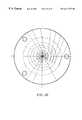
- FIG. 1is a schematic diagram illustrating a nineteen fiber circular layout, where concentric rings of fibers are seen to be beneficial, in terms of overall diameter of the bundle, in comparison to a hex pack according to the invention
- FIG. 2is a plot of the penalty associated with an increased number of fibers at a detector
- FIG. 3is a plot of diameter efficiency multiplied by the number of fibers as a function of the number of fibers, illustrating trade-off between illumination gain from increased detectors and loss from the associated lower efficiency;
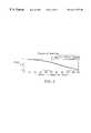
- FIG. 4is a plot of a monochromator output slit intensity illustrating the loss associated from fibers located horizontally off-center in the monochromator output slit;
- FIG. 5is a plot of the penalty associated with increased number of fibers at the monochromator
- FIG. 6is a plot of an additional penalty to keep fibers from being placed at the monochromator without receiving any light
- FIG. 7is a plot of an estimate of a signal using Monte Carlo simulations according to the invention.
- FIG. 8is a plot of an estimate of the function 1/Noise using a wide area radial fiber (WARF) probe according to the invention.
- WARFwide area radial fiber
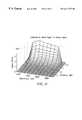
- FIG. 9is a three-dimensional plot of a near-IR (NIR) glucose signal-to-noise ratio as a function of wavelength and separation distance of illumination source and detector according to the invention.
- NIRnear-IR
- FIG. 10is a plot of an alternate view of an NIR glucose signal-to-noise ratio illustrating the peaks near the lowest separation distance according to the invention
- FIG. 11is a plot showing magnification of an NIR glucose signal-to-noise ratio in the combination band according to the invention.
- FIG. 12is a schematic diagram illustrating a hexagonal fiber optic interface according to the invention.
- FIG. 13is a schematic diagram illustrating a square fiber-optic interface according to the invention.
- FIG. 14is a schematic diagram illustrating a hexagonal arrangement with a circle superimposed showing how close a hexagon represents a circle for a hex pack according to the invention
- FIG. 15is a schematic diagram illustrating a square arrangement with a circle superimposed demonstrating slight losses associated with a square configuration versus a hexagon configuration according to the invention
- FIG. 16is a schematic diagram illustrating a hexagonal skin interface with a classification detector according to the invention.
- FIG. 17is a schematic diagram illustrating a 200/220 ⁇ m (core/clad) fiber optic pattern at a monochromator output slit, where a configuration of 105 fibers is shown (i.e. the exact amount), according to the invention
- FIG. 18is a schematic diagram illustrating an UltraSil fiber bundle termination at a detector optics termination, where a configuration of 52 fibers is shown, according to the invention.
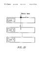
- FIG. 19is a schematic diagram illustrating a classification rectangle at skin interface (shown rotated 90 degrees) according to the invention.
- FIG. 20is a schematic diagram illustrating a rectangular skin interface with a classification detector according to the invention.
- FIG. 21is a coordinate scheme for a noninvasive tissue model
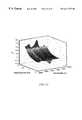
- FIG. 22is a plot showing the surface response of alpha ratio ( ⁇ 1 ) vs. radial collection distance and wavelength;
- FIG. 23is a plot showing the surface response of alpha ratio ( ⁇ 2 ) vs. radial collection distance and wavelength;
- FIG. 24is a plot showing surface response of alpha ratio ( ⁇ 3 ) vs. radial collection distance and wavelength;
- FIG. 25is a schematic diagram showing a WARF probe that is designed with a single illumination fiber radially surrounded by sets of six detection fibers at the following illumination-to-detection distances: 0.23, 0.77, 1.3, 2.08, 2.90, 3.71, 4.70, 6.70, 8.7, 10.7, 14.7 mm;
- FIG. 26is a plot showing intensity of noninvasive arm spectra vs. wavelength for various illumination-detection spacing
- FIG. 27is a plot showing coefficients, a ⁇ and b ⁇ , from data collected with a WARF probe and the resulting values;
- FIG. 28is a plot showing the magnitude of water absorbance at each detection point of the WARF probe (1-10), illustrating the classification by sex that occurs as the distance from the illumination fibers increases;
- FIG. 29is a plot showing estimated measurement noise (in absorbance units) for various illumination-to-detection distances at three separate wavelengths.
- FIG. 30is a plot showing the inter-, intra-, and total sample variation vs. illumination-to-detection distance.
- the inventionis directed to the development of an optimized fiber probe geometry for use in the area of diffuse reflectance and diffuse transmission spectroscopy. While the preferred embodiment of the invention is concerned with noninvasive measurements, other applications of the invention include measurements of moisture, fat, and protein in agricultural products, e.g. sugar in fruit or protein in cereal; reaction monitoring of slurry solutions; textile manufacturing; polymer melts, pellets, and additives; polymer tensile strength; active ingredients of pharmaceutical tablets; and active ingredients of gel caplets, to name a few. Such applications can be performed either during a QC/QA analysis, or they may be applied to real time process control.
- the inventionprovides a process for designing fiber optic bundles in specific patterns and shapes and distances (between illumination and detection fibers). Initially, the design is constrained to the use of specific fiber types and detector size, thereby simplifying the optimization process significantly (see Table 1 below).
- the inventionprovides a fiber optic bundle that includes both illumination and detection fibers.
- the detection and illumination fibershave the same characteristics, wherein said fiber characteristics comprise any of type, size, numeric aperture, and core-to-clad ratio.
- the buffer layershould be removed from the fiber ends in the preferred embodiment of the invention.
- the monochromator used in the preferred embodiment of the inventionis the Minichrome Monochromator manufactured by Optometrics of Ayer, Mass.
- the preferred detector sizeis prescribed to be 1 mm in diameter.
- the first of theseincludes a curve that estimates the intensity at the output slit of the monochromator.
- the secondis a function that approximates the efficiency of focusing the light from the detector fiber bundle through a long wave pass filter, two lenses, and a window, onto the detector itself.
- the signal of interest(which, in exemplary embodiment of the invention, is the absorbance attributable to glucose) is assumed to be proportional to the ratio of pathlength of the average photon in the dermis of the subject's skin to its total pathlength, i.e. the photon distribution along a mean path.
- a tissue modelwas developed and a Monte Carlo simulation (see below) run to estimate the average pathlength that the photon traveled, as well as what fraction of that pathlength was in the subject's dermis.
- the noiseis approximated using a noise model (see below), after some mathematical simplifications, of the intensity of the sample (e.g. the subject's arm). These data were generated from a wide area radial fiber (WARF) probe (described below). A function is then empirically fitted to the data. This function is used to generate the necessary representation of noise.
- WARFwide area radial fiber
- a third fiber optic field for detectionis included in the design because it significantly improves subject classification (see, for example, S. Malin, T. Ruchti, An Intelligent System for Noninvasive Blood Analyte Prediction, U.S. patent application Ser. No. 09/359,191, filed Jul. 22, 1999), which is believed to be an important precursor to algorithm application.
- optimizationmeans the maximization of a cost or evaluation function in some manner based upon a pre-defined set of mathematical operations.
- the evaluation functionis an estimate of the modeled signal-to-noise ratio. The optimization criterion maximizes the sum of this evaluation function in a portion of the combination band (2100-2250 nm) that is deemed to be representative of the glucose molecule's absorption in that region.
- the detector fiber bundleis preferably the same shape as the detector (i.e. circular) to maximize the amount of light leaving the detector fibers that strikes the detector. Consequently, the optimal arrangement of the detector fibers at the lens is circular. As the number of detector fibers increases, both the amount of space these fibers occupy and the radius of the fiber bundle increase. The fibers at the perimeter of the fiber bundle contribute less light to the detector than the fibers at the center of the bundle. Additionally, because the image of the fiber bundle is constrained to the size of the detector and the magnification is finite, optical radiation is collected less efficiently with an increased bundle size.
- This effectcan be quantified using a ZemaxTM Raytrace model (manufactured by Focus Software, Inc. of Arlington, Ariz.) to provide an overall efficiency of light delivered to the detector as a function of the fiber bundle radius, once the location and specifications for the lenses and any other elements in the optical paths are established. The efficiency can then be considered as a detector radius penalty that allows for optimization of the detector fiber bundle.
- the actual cost function associated with fiber bundle radiusis to best determine the optimal number of detector fibers.
- FIG. 2the loss of light efficiency as the number of fibers increases can be seen. Counteracting this loss of efficiency is the increased amount of light delivered by the larger number of fibers.
- FIG. 3illustrates the region of interest used to determine the optimal tradeoff between increasing the number of fibers and detector optical design efficiency. Initially, as the number of detection fibers increases, the weight function increases. However, at a point around 54 fibers, the extra light from adding additional fibers is overshadowed by the increased loss in efficiency. Therefore, nothing is gained by adding further fibers.
- detector fibersare preferably positioned with a bundle center fiber at the detector being likewise centered at the fiber bundle interface at the subject's dermis so that the center fiber is at the center at each end of the bundle.
- This arrangementis preferably applied to each and every fiber in the bundle, e.g. outermost fibers are outermost at each end.
- the output slit of the monochromatoris rectangular resulting in a rectangular best shape for the monochromator fiber bundle. This suggests to one skilled in the art the use of a hexagonal packing arrangement to maximize the packing fraction, which in turn maximizes the amount of light collected from the monochromator.
- the optical dimensions of the monochromatorhelp to determine the optimal size of the monochromator fiber bundle.
- the height for the monochromator slitshould be less than 1 mm.
- the number of fibers in each row as well as the width of the fiber bundlecan be calculated.
- illumination fibersare preferably positioned with a bundle center fiber at the monochromater slit being likewise centered at the fiber bundle interface with the subject (the subject's dermis is an inner portion of skin tissue, hence the fiber bundle interface does not occur at the dermis) so that the center fiber is at the center at each end of the bundle.
- This arrangementis preferably applied to each and every fiber in the bundle, e.g. outermost fibers are outermost at each end.
- FIG. 4illustrates the results of three such raytrace simulations and their average used in the simulations. Assuming, for the sake of simplicity, a uniform distribution of fibers at the monochromator output slit, the average intensity in each illumination fiber can be computed. The value of the raytrace results is averaged (over the computed monochromator slit height) to obtain a scale factor for the entire monochromator fiber bundle (see FIG. 5 ). This scale factor is a number between 0 and 1 that represents what fraction of the maximum intensity (which is defined to be 1.0 at the center of the monochromator output slit) each illumination fiber is assumed to carry.
- Data for estimating the noiseis obtained using the WARF probe with a first type of fibers F1, e.g. 300/330/370 ⁇ m (i.e. core/clad/buffer).
- F1a first type of fibers
- F2e.g. 300/330/370 ⁇ m
- certain scaling factorsmust be taken into consideration.
- the amount of light delivered to the skinis proportional to the area of the illumination fiber.
- the amount of light collected at the skinis proportional to the area of the detector fiber.
- SF( Diameter ⁇ ⁇ of ⁇ ⁇ F2 ⁇ ⁇ Detector ⁇ ⁇ Core Diameter ⁇ ⁇ of ⁇ ⁇ F1 ⁇ ⁇ Detector ⁇ ⁇ Core ) 2 ⁇ ( Diameter ⁇ ⁇ of ⁇ ⁇ F2 ⁇ ⁇ Illlumination ⁇ ⁇ Core Diameter ⁇ ⁇ of ⁇ ⁇ F1 ⁇ ⁇ Illumination ⁇ ⁇ Core ) 2 ( 2 )
- F2is a second type of fiber, e.g. 200/220 ⁇ m, 200/240 ⁇ m (i.e. core/clad).
- the data collected with the WARF probeconsiders the effect of one fiber placed in the center of a ring of six fibers. Depending on whether the one center fiber is a collection or illumination fiber (and the six fibers are illumination and collection fibers, respectively), intensity variations arise due to inefficiencies in the detector optics. For the simulations, it is desired to determine what effect one illumination fiber has on one detection fiber when completely focused on the detector. To do this, a comparison between the above-described cases is made and a scale factor of 1.475 is determined to be the appropriate scale factor.
- the signal of interestin this instance the absorbance due to glucose, is assumed (via Beer's Law) to be proportional to the pathlength of the light as it travels through the dermis, referred to as L Dermis . Additionally, because glucose is located predominantly in the vascularized portion of the dermis, the glucose signal is better represented by the fraction of the pathlength in the dermis when divided by the overall pathlength (L Dermis /L Total ). In a medium in which intensity does not diminish with fiber separation distance, the best scenario for detecting the glucose signal is the one received with a maximum L Dermis /L Total term. For that case, whatever fiber optic pattern that yields a maximum for that term is preferential to all others, although other signal definitions are possible.
- N R and N Sare the noise in the reference and sample intensity measurements, respectively, and I R and I S are the intensities in the reference and sample, respectively.
- I R and I Sare the intensities in the reference and sample, respectively. This simplifies (given several assumptions) to a value that is proportional to 1/I S in the instance where the system is dominated by sample noise (which is the case).
- a function representing the sample intensity as a function of distance (separation between fibers) and wavelengthadequately models the noise.
- a ⁇ and b ⁇are empirically derived parameters for each wavelength, and d is the fiber separation distance.
- the contribution of the WARF probe results to the overall cost functionis that it estimates the noise portion of the signal-to-noise ratio.
- Data on the WARF probeexists across the wavelength ranges of interest, as well as at varying distances (separation of illumination and detection fibers). A description of that system is beyond the scope of the discussion herein. The data were compiled and curve fitted for ease of representation and computation (see FIG. 8 ).
- This evaluation functiontakes into consideration the separation in fiber distances, the SNR (signal-to-noise ratio), and the various aspects of the monochromator output slit and detector optics stack.
- EF iis the evaluation function for the i th detector
- the signal, S, and noise, Nare functions of wavelength, ⁇ , and illumination to detection fiber separation distance d
- DPis the detector penalty as a function of the number of detection fibers
- MPis the monochromator penalty as a function of the number of illumination fibers
- MSPis the monochromator size penalty as a function of the number of illumination fibers
- SFis a scaling factor that is a function of fiber sizes and types.
- the evaluation functionpredicts the intensity off of an arm scan. This allows for model validation on a F1 fiber probe or on any custom bundle that is designed.
- the best design for a given detection fiberis the one that maximizes the evaluation function for that detector over the wavelength range of interest, here 2100-2250 nm.
- the genetic algorithmproduces a result similar to that displayed in FIG. 12 .
- Black circles Brepresent illumination fibers and the gray circles R and G are 1.9 ⁇ m and 2.6 ⁇ m detection fibers.
- the basic patterncomprises alternating columns of illumination and detection fibers.
- the perimeter displayedis approximately a square (see FIG. 13 ). However, if it is feasible to build a fiber bundle having a hexagonal perimeter, there is a gain in the net signal.
- the perimeteris a circle.
- the closest approximation to a circle with hex-packed fibersis a hexagon, as shown in FIG. 14.
- a squareis also feasible, coming within about 5% of the predicted results given by a hexagon. Compare the plot of FIG. 14 which is for a hexagon configuration with the plot of FIG. 15 which is for a square configuration. Both plots have circles superimposed on them to show how close these perimeters are to the ideal case.
- the optimization of the evaluation functionyields an optimal pattern.
- the perimeteris incorporated that encloses a sufficient number of fibers (e.g. greater than or equal to the optimal number), and a classification fiber group is added an appropriate distance away, the result is shown in FIG. 16 .
- This configurationcontains 217 fibers in the main hex pattern (109 illumination fibers and 108 detection fibers—54 fibers of each type) and a group of 56 fibers in the classification group. Because only 105 illumination fibers are required and desirable, four of the fibers B shown in solid black are not connected to the monochromator output slit bundle termination (see FIG. 17 ). They are effectively dead fibers at the skin interface.
- each detection fiber R, G shown in grayis not included in the termination at the detector optics (see FIG. 18 ).
- Four fibers in the classification bundleare not included in that particular termination (see FIG. 19 ). This allows for some tolerance of broken, cracked, or dead fibers after the skin interface termination of the fiber bundle is manufactured.
- R, G fiber detection fiber patternAlternating rows with unique center row of alternating detection fibers.
- R, G fiber detection fiber patternAlternating rows with unique center row alternating detection fibers.
- Extrapolation of WARF probe datais reliable.
- the closest separation distances (center to center) seen by the WARF probewere just over 0.5 mm.
- the majority of the signals in the designed probeare in fibers that are 0.25 and 0.4 mm apart. As such, this represents an extrapolation of the data from the WARF probe.
- the empirical modelrepresents the light intensity detected versus illumination-to-detection distance given the light delivered to the sample by a single fiber. At close distances ( ⁇ 3-4 mm), where the detected signal is greatest, the error in the model is small.
- the coefficients of the modelare purposely biased to represent distance configurations in which the sampled tissue volume is predominantly the dermal layer.
- the heterogeneity of the sample and in particular the multi-layer composition of the skincauses a decrease in model accuracy. Consequently, the model appears to represent the empirical data when absorbance is dominated by the dermis, but does not accurately represent absorbance due to subcutaneous tissue.
- a 235 ⁇ m separation center-to-centeris representative of a mixed bundle of 225 ⁇ m and 245 ⁇ m diameter fibers.
- the mean of the two fiber diametersis used to find the distances which, in turn, is used to compute the signal and noise function for a given illumination and detection pair of fibers.
- the WARF probe resultscan be linearly scaled to represent smaller core diameter fibers.
- the WARF probeused 375 ⁇ m diameter fibers and the current design is using 225 and 245 ⁇ m core fibers. It is assumed that the ratio of areas (235 2 /375 2 ) of the two fibers accurately represents the total signal attenuation per fiber.
- the diameter of the fiber core(200 ⁇ m in this case) is also a significant distance in terms of how quickly light attenuates in the skin.
- a new WARF probe with fibers having 200 ⁇ m cores radially distributed at 235 and 400 ⁇ m spacingis necessary to generate a more accurate noise model.
- the monochromator intensity profileis not uniform across the center. This is a result of using a raytrace program to model the intensity profile.
- the design disclosed hereinis insensitive to those variations. Rather, a more important aspect of that intensity profile is the edges, which on the raytraces are well defined. It is those edges which determine the overall range in which light can be collected from the monochromator and hence the maximum number of illumination fibers that could potentially deliver light to the skin.
- the theoretical fiber packingis not similar to the simulation at the detector optics. Even with the assumption of the average packing fraction being used to determine the detector optics efficiency, the manner in which the fibers are placed into that termination is random. However, the variation is approximately a linear scaling factor, which, as already discussed, these optimizations can tolerate.
- the decision to optimize for the combination bandis correct.
- Other optionsare to optimize for the first or second overtone. Because of the shape of the signal-to-noise function, the design is identical if an optimization is performed for the first overtone or a combination of the first overtone and combination band. The second overtone, however, yields something different. Currently, it is believed that reading glucose occurs in either the combination band or the first overtone. If correct, the optimization decision is not of critical importance.
- This approachinvolves the development of a strategy to assess diffuse reflectance light sampling proficiency based on a given optical interface design.
- System parameterssuch as the total pathlength, pathlength through a tissue region, penetration depth, or diffuse reflectance contributions from a particular tissue region can be used to generate a mathematical representation of the desired response (e.g. blood glucose absorption signal) for a given set of inputs.
- These inputsmay include the radial collection distance from a source to detection arrangement, or even the depth of photon propagation into the tissue.
- the goalis to obtain a figure of merit, such that quantitative assessments can be made regarding the measurement system and its relation to blood glucose levels.
- the measurement of interestcan be as direct as an absorption signal from a chemical constituent such as blood glucose or an intensity signal that yields an optimal configuration for light recovery and ultimately an improved net analyte signal. No matter what the measurement of interest is, a similar procedure is followed to obtain the mathematical model. Additionally, each procedure must consist of a set of criteria that governs the decision making process and how the measurement is interpreted. Several approaches to assessing the optimal values for a given optical system have been developed and explored.
- the original optimization strategywas to use the proportion of reflectance that had penetrated to the dermal layer of the tissue model and divide that by the total amount of reflectance measured for a given radial collection distance. This procedure was then performed at every wavelength. The ratio is constrained between values of 0 and 1. The calculation of this parameter was achieved by scoring the reflectance results from a Monte Carlo simulation and then by taking the sum of the dermal reflectance contribution from a noninvasive tissue model and normalizing it with the diffuse reflectance contribution (R D ) at a particular radial collection distance and wavelength.
- nis the first element of the dermal layer and N is the last element of the dermal layer as depicted in FIG. 21 .
- the average dermal pathlength ⁇ l Dermis (r, ⁇ )>is the arithmetic mean of each pathlength scored in the dermal layer for a given radial collection distance and wavelength whereas, the average total pathlength ⁇ l Total (r, ⁇ )> is the arithmetic mean of all pathlengths measured at the same radial collection distance and wavelength.
- the response surfaceis quite similar to that shown in FIG. 22, except that the decrease as a function of radial collection distance is not as dramatic. This is attributed to the addition of the pathlength term. Also, the model fit is not realistic at radial collection distances greater than ⁇ 1.0 cm. In addition, the characteristics of the response still favor an optical configuration that will maximize the light intensity returning from the system. This is independent of the desired signal of interest so, it is not the most desirable approach.
- the average dermal pathlengthis calculated by taking the arithmetic mean of the individual dermal layer contributions whereas, the average total pathlength is calculated by taking the arithmetic mean of all layer contributions.
- Equation (10)is a more desirable relationship because it yields a maximum value that is correlated to the net analyte signal (e.g. blood glucose signal) for a given optical design.
- the net analyte signalcan be viewed as the absorbance due to glucose. This is assumed to follow the Beer's Law relationship. This relationship mathematically states that the absorbance of a system is proportional to the pathlength of photon propagation through the system. Because the absorbance of the system is composed of the net analyte signal and additional contributions, the average pathlength is then proportional to the net analyte signal.
- the most effective system parameter for use in the optimization of different optical design schemesis to use the ratio of the average dermal pathlength with the average total pathlength ( ⁇ 3 ). This most directly addresses the need for a system parameter that is proportional to the net analyte signal and includes additional features that are desirable to an overall reflectance measurement.
- the other system parameters presentedwere not directly related to the signal of interest, In this case, a blood glucose signal. However, they may still offer utility in other optical design applications in which the light intensity returning from the system is critical.
- the noise modelis the denominator of the signal-to-noise ratio that is used to evaluate and optimize fiber geometries.
- the requirement for the modelis to provide an estimate of the noise, in absorbance units at specified wavelengths and for a particular illumination-to-detection fiber distance.
- the form of the developed modelis given by
- N A0is the RMS noise in absorbance units
- ⁇is the wavelength
- dis the distance between the illumination and detection fibers (for a particular fiber diameter)
- f( ⁇ )is a nonlinear function.
- the structure and parameters for f( ⁇ )are determined empirically for each target application and measurement approach, such as the noninvasive measurement of blood glucose.
- Equation 13is applied specifically for a diffuse reflectance measurement, the approach can be applied to any for of spectroscopic measurement by propagation of noise through the equation used to calculate the analytical signal.
- the noise of the measurement systemis inversely proportional to the intensity that is diffusely reflected off of the sample and detected. Therefore, a model needs to be constructed that returns I s , for an arbitrary illumination-to-detection fiber spacing, d, and for each wavelength, ⁇ , of interest.
- This modelcan be determined through Monte Carlo simulations (discussed above) or lumped parameter scattering models given the scattering properties of the target sample, such as the tissue.
- the preferred methodis to determine the model for I S empirically through the use of a wide angle radial fiber-optic (WARF) probe as described below.
- WARFwide angle radial fiber-optic
- a wide angle radial fiber-optic probewas designed to provide an empirical measurement method for determining the model
- I Sis the light intensity detected from a single fiber at a distance, d, from the single illumination fiber and ⁇ is the wavelength. Further, the WARF probe is utilized to determine the optimal distance for a separate classification bundle as described below.
- the WARF probedepicted in FIG. 25, was designed with a single illumination fiber radially surrounded by sets of six detection fibers at the following illumination-to-detection distances: 0.23, 0.77, 1.3, 2.08, 2.90, 3.71, 4.70, 6.70, 8.7, 10.7, 14.7 mm. While the present configuration is optimized for spectroscopic measurement of skin tissue, the invention is easily generalized to alternate illumination-to-detection distances given alternate samples. In addition, the number of detection fibers can be modified to accommodate the requirements of other samples or for coupling to any spectrometer.
- each set of six fibersare coupled to a detector of a custom designed spectrometer consisting of a quartz halogen lamp, a scanning monochromater and InGAs and extended InGAs detectors. Therefore, the WARF probe provides eleven different illumination-to-detection distances.
- the probecan be coupled to any commercially available NIR spectrometer such as a Foss-NIRSystems Model 5000 spectrometer or a Nicolet Magna-IR 760 spectrometer.
- Equation 16An empirical model (Equation 16) was developed to represent the detected intensity over all wavelengths and illumination-to-detection distances and is given by
- a ⁇represents a baseline offset
- b ⁇is analogous to the sum of all extinction coefficients
- c ⁇provides a general method for accommodating various sample types.
- the modelis simplified to
- I Se ⁇ (a ⁇ +b ⁇ ⁇ square root over (d) ⁇ ) ( 18)
- Weighted least-squares optimizationwas applied to determine the coefficients, a ⁇ and b ⁇ , from data collected with the WARF probe and the resulting values are provided in FIG. 27 .
- the absorbance (and average pathlength)increases according to the square-root of the distance between illumination and detection.
- the empirical modelrepresents the light in tensity detected versus illumination-to-detection distance given the light delivered t o the sample by a single fiber. At close distances ( ⁇ 3-4 mm) the error in the model is small.
- the coefficients of the modelwere purposely biased through the weighted least-squares calculation to represent distance configurations in which the sampled tissue volume is predominantly the dermal layer. Therefore, at greater distances, the heterogeneity of the sample and in particular the multi-layer composition of the skin, causes a decrease in model accuracy. Consequently, the model appears to represent the empirical data when absorbance is dominated by the dermis but does not accurately represent absorbance due to subcutaneous tissue. In alternate configurations the weighted least-squares method for determining the parameters is performed to optimize the accuracy of the target penetration depth.
- the fiber geometry optimization procedureis performed to optimize the sampling of the target analyte signal that is located in a specific volume of the sample.
- the need for subject classificationhas been demonstrated by S. Malin et al, An Intelligent System for Noninvasive Blood Analyte Prediction, supra.
- Such a classificationmay not be possible through an optimal sampling of the dermis.
- the classification according to subject sexshown by T. Ruchti, S. Malin, J. Rennert, Classification of Individuals Based on Features Related to Sex, U.S. Provisional Patent Application Ser. No. 60/116,883, filed Jan.
- the methodinvolves the use of the following criterion:
- Classification performancethe spacing that provides classification performance according to the target sample characteristic or quality.
- Noisewithin the desired classification performance the distance that provides the lowest noise level in absorbance.
- Inter-Sample Precisionwithin the desired classification performance the distance that is least influences by variation of the target sample.
- the WARF probeis used to construct a data set, as described above, to perform analysis associated with each criterion.
- the water absorbance of each sample at each illumination-to-detection distance for each subjectwas determined as described by Ruchti et al, Classification of Individuals Based on Features Related to Sex, supra. Plots of the results are shown in FIG. 28 and demonstrate that the water absorbance feature is adequately determined for illumination-to-detection distances that are greater than 3 mm.
- FIG. 29shows the noise in absorbance units versus illumination-to-detection distances averaged over all subjects. From FIG. 29 it is apparent that the noise is lowest at smaller distances and therefore a distance of 3 mm is preferred.
- FIG. 30is a plot of the inter-sample, intra-sample and total spectral variation versus illumination-to-detection distance over all subjects.
- the plotshows the pooled variance within a sample, the pooled variance between samples and the total variance. From the plot of total variation 3 mm is found to be optimal in terms of measurement precision.
- the method of optimizationinvolves the configuration of the cost function, the implementation of a set of constraints and the search for a set of parameters providing the best performance.
- the implementation of constraintswas discussed based on mechanical considerations and available materials.
- the resulting unknown variablesare parameters that must be determined according to the performance as reflected by the cost function.
- unknown variablescan include the fiber diameter, the quantity of fibers and the location of the fibers.
- Selection of the parametersis accomplished through methods of optimization such as dynamic programming (see R. Bellman, Dynamic Programming , Princeton University Press, Princeton, N.J., USA (1957)), gradient search techniques (see P. Gill, W. Murray, M. Wright, Practical Optimization , Academic Press (1981)), random search techniques, genetic algorithms (see D. Goldberg, Genetic Algorithm in Search, Optimization and Machine Learning , Addison Wesley Publishing Company (1989)), or evolutionary programming (see D. Fogel, An Introduction to Simulated Evolutionary Optimization , IEEE Trans. On Neural Networks, vol. 5, no. 1 (January 1994)). Given a cost function and a set of parameters one skilled in the art can appreciate that any of these methods can be applied to determine an optimal or near-optimal solution.
- a genetic algorithmis employed to select from a given solution set of fibers which are used for illumination, for detection and which are not used.
- the methodnecessitates the encoding of chromosomes comprised of genes, each representing a fiber.
- the genescan take on the following values: 0-not used, 1-illumination fiber, 2-lower wavelength range detection fiber, 3-upper wavelength range detection fiber.
- the genetic algorithmis initialized with a population of possible solutions with each solution representing a different fiber geometry system. Each solution is evaluated through the cost function and assigned a performance measure. The solutions are combined (through reproduction operations) at a rate determined by their respective performance. Consequently, poorly performing solution are not selected for further use while superior configurations are combined and randomly modified. Through many iterations of this procedure a near-optimal solution is provided from a global set of possible solutions.
- the discussion hereindiscloses the design process used to determine the pattern of detection and illumination optical fiber bundles for the sampling of the NIR spectrum of a subject's skin.
- Information about the systemspecifically the monochromator output slit (to determine the optimal number of illumination fibers) and the bundle termination at the detector optics stack (to determine the optimal number of detection fibers) are both of critical importance to this design. It is those numbers that determine the ratio and number of illumination to detection fibers, significantly limiting and constraining the solution space. Additionally, information about the estimated signal and noise in the skin are essential to maximize the signal-to-noise ratio in the wavelength range of interest.
- Resultsindicate that constraining the fibers to a hexagonal perimeter and prescribing a hex-packed pattern, such that alternating columns contain illumination and detection fibers, yields optimal results.
- Two detectorsshare the totality of the detection fibers at the sampling interface.
- a third group of detection fibersare used for classification purposes. In the event of any number of manufacturing issues associated with fabrication of these hexagonal bundles, a rectangular design is disclosed for implementation in place of the hexagonal design.
Landscapes
- Physics & Mathematics (AREA)
- Health & Medical Sciences (AREA)
- Life Sciences & Earth Sciences (AREA)
- Chemical & Material Sciences (AREA)
- Analytical Chemistry (AREA)
- Biochemistry (AREA)
- General Health & Medical Sciences (AREA)
- General Physics & Mathematics (AREA)
- Immunology (AREA)
- Pathology (AREA)
- Investigating Or Analysing Materials By Optical Means (AREA)
- Measurement Of The Respiration, Hearing Ability, Form, And Blood Characteristics Of Living Organisms (AREA)
- Spectrometry And Color Measurement (AREA)
- Investigating, Analyzing Materials By Fluorescence Or Luminescence (AREA)
Abstract
Description
| TABLE 1 |
| Preferred Fiber Types |
| Numerical | |||
| Fiber | Specific Type | Aperture (NA) | Size (Core/Clad) |
| Illumination | UltraSil 200T* | 0.22 | 200/240 μm |
| Detection | TCL-MA200H* | 0.29 | 200/220 μm |


| TABLE 2 |
| Target Design Goals and Fiber Specific Information, |
| Hexagonal Bundle |
| Number at | Number of | Fiber NA and Size | ||
| Number at | Detector or | Dead Fibers | w/o Buffer | |
| Fiber Type | Skin | Monochromator | at Skin | (Core/Clad) in μm & |
| or Use | Interface | Interface | Interface | Fiber Name |
| Illumination | 109 | 105 | 4 (if possible, | 0.22 NA & 200/225* |
| Fibers | select unused | TCL-MA200H | ||
| fibers at | ||||
| corners) | ||||
| 54 | >=52 | <=2 | 0.29 NA & 200/245* | |
| Fibers 1.9 | UltraSil | |||
| μm (main) | ||||
| 54 | >=52 | <=2 | 0.29 NA & 200/245* | |
| Fibers 2.6 | UltraSil | |||
| μm (main) | ||||
| 56 | >=52 | <=4 | 0.29 NA & 200/245* | |
| Fibers 1.9 | UltraSil | |||
| μm (additional) | ||||
| *+5 μm for tolerances | ||||
| TABLE 3 |
| Target Design Goals and Fiber Specific Information, |
| Rectangular Bundle |
| Number at | Number of | Fiber NA and Size | ||
| Number at | Detector or | Dead Fibers | w/o Buffer | |
| Fiber Type | Skin | Monochromator | at Skin | (Core/Clad) in μm & |
| or Use | Interface | Interface | Interface | Fiber Name |
| Illumination | 112 | 105 | 7 (if possible, | 0.22 NA & 200/225* |
| Fibers | select unused | TCL-MA200H | ||
| fibers at | ||||
| corners) | ||||
| 56 | >=52 | <=4 | 0.29 NA & 200/245* | |
| Fibers 1.9 | UltraSil | |||
| μm (main) | ||||
| 56 | >=52 | <=4 | 0.29 NA & 200/245* | |
| Fibers 2.6 | UltraSil | |||
| μm (main) | ||||
| 56 | >=52 | <=4 | 0.29 NA & 200/245* | |
| Fibers 1.9 | UltraSil | |||
| μm (additional) | ||||
| *+5 μm for tolerances | ||||


Claims (30)


Priority Applications (14)
| Application Number | Priority Date | Filing Date | Title |
|---|---|---|---|
| US09/415,389US6411373B1 (en) | 1999-10-08 | 1999-10-08 | Fiber optic illumination and detection patterns, shapes, and locations for use in spectroscopic analysis |
| AU77479/00AAU7747900A (en) | 1999-10-08 | 2000-10-02 | Optimizing a fiber-optic probe for spectroscopic measurements |
| PCT/US2000/027164WO2001027597A1 (en) | 1999-10-08 | 2000-10-02 | Optimizing a fiber-optic probe for spectroscopic measurements |
| EP00967255AEP1218725B1 (en) | 1999-10-08 | 2000-10-02 | Optimizing a fiber-optic probe for spectroscopic measurements |
| DE60037437TDE60037437T2 (en) | 1999-10-08 | 2000-10-02 | OPTIMIZING A LIGHTING PROBE FOR SPECTROSCOPIC MEASUREMENTS |
| AT00967255TATE381012T1 (en) | 1999-10-08 | 2000-10-02 | OPTIMIZATION OF A LIGHT GUIDE PROBE FOR SPECTROSCOPIC MEASUREMENTS |
| CA002385277ACA2385277A1 (en) | 1999-10-08 | 2000-10-02 | Optimizing a fiber-optic probe for spectroscopic measurements |
| JP2001530558AJP2003511693A (en) | 1999-10-08 | 2000-10-02 | Optimization of fiber optic probe for spectrophotometry |
| HK02107160.7AHK1046953B (en) | 1999-10-08 | 2000-10-02 | Optimizing a fiber-optic probe for spectroscopic measurements |
| CNB008139768ACN100501379C (en) | 1999-10-08 | 2000-10-02 | Optimizing Fiber Optic Probes for Spectral Measurements |
| TW089120966ATW490555B (en) | 1999-10-08 | 2000-10-09 | Fiber optic illumination and detection patterns, shapes, and locations for use in spectroscopic analysis |
| NO20021626ANO20021626L (en) | 1999-10-08 | 2002-04-05 | Optimization of a fiber optic probe for spectroscopic measurements |
| US10/820,322US7299080B2 (en) | 1999-10-08 | 2004-04-07 | Compact apparatus for noninvasive measurement of glucose through near-infrared spectroscopy |
| US10/978,116US7317938B2 (en) | 1999-10-08 | 2004-10-29 | Method of adapting in-vitro models to aid in noninvasive glucose determination |
Applications Claiming Priority (1)
| Application Number | Priority Date | Filing Date | Title |
|---|---|---|---|
| US09/415,389US6411373B1 (en) | 1999-10-08 | 1999-10-08 | Fiber optic illumination and detection patterns, shapes, and locations for use in spectroscopic analysis |
Related Parent Applications (2)
| Application Number | Title | Priority Date | Filing Date |
|---|---|---|---|
| US10/472,856Continuation-In-PartUS7133710B2 (en) | 1999-10-08 | 2003-03-07 | Compact apparatus for noninvasive measurement of glucose through near-infrared spectroscopy |
| PCT/US2003/007065Continuation-In-PartWO2003076883A2 (en) | 1999-10-08 | 2003-03-07 | Compact apparatus for noninvasive measurement of glucose through near-infrared spectroscopy |
Related Child Applications (1)
| Application Number | Title | Priority Date | Filing Date |
|---|---|---|---|
| US87752901AContinuation-In-Part | 1999-10-08 | 2001-06-08 |
Publications (1)
| Publication Number | Publication Date |
|---|---|
| US6411373B1true US6411373B1 (en) | 2002-06-25 |
Family
ID=23645502
Family Applications (1)
| Application Number | Title | Priority Date | Filing Date |
|---|---|---|---|
| US09/415,389Expired - Fee RelatedUS6411373B1 (en) | 1999-10-08 | 1999-10-08 | Fiber optic illumination and detection patterns, shapes, and locations for use in spectroscopic analysis |
Country Status (12)
| Country | Link |
|---|---|
| US (1) | US6411373B1 (en) |
| EP (1) | EP1218725B1 (en) |
| JP (1) | JP2003511693A (en) |
| CN (1) | CN100501379C (en) |
| AT (1) | ATE381012T1 (en) |
| AU (1) | AU7747900A (en) |
| CA (1) | CA2385277A1 (en) |
| DE (1) | DE60037437T2 (en) |
| HK (1) | HK1046953B (en) |
| NO (1) | NO20021626L (en) |
| TW (1) | TW490555B (en) |
| WO (1) | WO2001027597A1 (en) |
Cited By (292)
| Publication number | Priority date | Publication date | Assignee | Title |
|---|---|---|---|---|
| US20020175287A1 (en)* | 2001-03-08 | 2002-11-28 | Busch Kenneth W. | Dispersive near-infrared spectrometer with automatic wavelength calibration |
| US20040210545A1 (en)* | 2001-10-31 | 2004-10-21 | Juergen Branke | Method and system for implementing evolutionary algorithms |
| US20040232237A1 (en)* | 2000-01-17 | 2004-11-25 | Evolvable System Research Institute, Inc. | Optical apparatus, optical apparatus adjustment method, and storage medium recorded with a processing program that executes said adjustment method |
| US20050010090A1 (en)* | 2002-03-08 | 2005-01-13 | George Acosta | Compact apparatus for noninvasive measurement of glucose through near-infrared spectroscopy |
| US20050054908A1 (en)* | 2003-03-07 | 2005-03-10 | Blank Thomas B. | Photostimulation method and apparatus in combination with glucose determination |
| US20050119983A1 (en)* | 2003-08-27 | 2005-06-02 | Eric Bonabeau | Methods and systems for multi-participant interactive evolutionary computing |
| US20050118612A1 (en)* | 2003-08-01 | 2005-06-02 | Icosystem Corporation | Methods and systems for applying genetic operators to determine system conditions |
| US20050159656A1 (en)* | 2003-03-07 | 2005-07-21 | Hockersmith Linda J. | Method and apparatus for presentation of noninvasive glucose concentration information |
| US20050187439A1 (en)* | 2003-03-07 | 2005-08-25 | Blank Thomas B. | Sampling interface system for in-vivo estimation of tissue analyte concentration |
| US20050203359A1 (en)* | 2000-05-02 | 2005-09-15 | Blank Thomas B. | Optical sampling interface system for in-vivo measurement of tissue |
| US20050236563A1 (en)* | 2002-03-08 | 2005-10-27 | Busch Kenneth W | Dispersive near-infrared spectrometer with automatic wavelength calibration |
| US20060010117A1 (en)* | 2004-07-06 | 2006-01-12 | Icosystem Corporation | Methods and systems for interactive search |
| US20060189858A1 (en)* | 2005-02-14 | 2006-08-24 | Sterling Bernhard B | Analyte detection system for multiple analytes |
| US20060195204A1 (en)* | 2003-04-04 | 2006-08-31 | Icosystem Corporation | Methods and Systems for Interactive Evolutionary Computing (IEC) |
| US20060200017A1 (en)* | 2002-03-08 | 2006-09-07 | Monfre Stephen L | Noninvasive targeting system method and apparatus |
| US20060206018A1 (en)* | 2005-03-04 | 2006-09-14 | Alan Abul-Haj | Method and apparatus for noninvasive targeting |
| US20060211931A1 (en)* | 2000-05-02 | 2006-09-21 | Blank Thomas B | Noninvasive analyzer sample probe interface method and apparatus |
| US20070019199A1 (en)* | 2005-07-25 | 2007-01-25 | The Wisconsin Alumni Research Foundation | Methods, systems, and computer program products for optimization of probes for spectroscopic measurement in turbid media |
| US20070067212A1 (en)* | 2005-09-21 | 2007-03-22 | Eric Bonabeau | System and method for aiding product design and quantifying acceptance |
| US20070067279A1 (en)* | 2004-07-06 | 2007-03-22 | Icosystem Corporation | Methods and Apparatus for Interactive Searching Techniques |
| US20070149868A1 (en)* | 2002-03-08 | 2007-06-28 | Blank Thomas B | Method and Apparatus for Photostimulation Enhanced Analyte Property Estimation |
| US20070203405A1 (en)* | 2004-10-15 | 2007-08-30 | Yoshiaki Shimomura | Instrument For Noninvasively Measuring Blood Sugar Level |
| US20070234300A1 (en)* | 2003-09-18 | 2007-10-04 | Leake David W | Method and Apparatus for Performing State-Table Driven Regression Testing |
| US20070232932A1 (en)* | 2006-03-17 | 2007-10-04 | Duke University | Monte Carlo based model of fluorescence in turbid media and methods and systems for using same to determine intrinsic fluorescence of turbid media |
| US20070298866A1 (en)* | 2006-06-26 | 2007-12-27 | Paolo Gaudiano | Methods and systems for interactive customization of avatars and other animate or inanimate items in video games |
| US20080033275A1 (en)* | 2004-04-28 | 2008-02-07 | Blank Thomas B | Method and Apparatus for Sample Probe Movement Control |
| US20080208018A1 (en)* | 2001-04-11 | 2008-08-28 | Trent Ridder | Apparatuses for Noninvasive Determination of in vivo Alcohol Concentration using Raman Spectroscopy |
| US20080270091A1 (en)* | 2007-02-23 | 2008-10-30 | Nirmala Ramanujam | Scaling method for fast monte carlo simulation of diffuse reflectance spectra from multi-layered turbid media and methods and systems for using same to determine optical properties of multi-layered turbid medium from measured diffuse reflectance |
| US20080319286A1 (en)* | 2004-05-24 | 2008-12-25 | Trent Ridder | Optical Probes for Non-Invasive Analyte Measurements |
| US20080319299A1 (en)* | 2004-04-28 | 2008-12-25 | Stippick Timothy W | Method and apparatus for controlling positioning of a noninvasive analyzer sample probe |
| US20080319382A1 (en)* | 2002-03-08 | 2008-12-25 | Blank Thomas B | Method and apparatus for coupling a channeled sample probe to tissue |
| US20090003764A1 (en)* | 2004-05-24 | 2009-01-01 | Trent Ridder | Method of Making Optical Probes for Non-Invasive Analyte Measurements |
| US20090015826A1 (en)* | 2006-03-30 | 2009-01-15 | Duke University | Optical assay system for intraoperative assessment of tumor margins |
| US7519406B2 (en) | 2004-04-28 | 2009-04-14 | Sensys Medical, Inc. | Noninvasive analyzer sample probe interface method and apparatus |
| KR100892143B1 (en) | 2008-09-05 | 2009-04-15 | 퀀텀메딕스(주) | Optical device for skin treatment and formation method of irradiation pattern for skin treatment |
| US20090144617A1 (en)* | 2007-02-01 | 2009-06-04 | Pablo Funes | Method and system for fast, generic, online and offline, multi-source text analysis and visualization |
| US20090234204A1 (en)* | 2004-05-24 | 2009-09-17 | Trent Ridder | Methods for Noninvasive Determination of in vivo Alcohol Concentration using Raman Spectroscopy |
| US20090247840A1 (en)* | 2002-03-08 | 2009-10-01 | Sensys Medical, Inc. | Method and apparatus for coupling a sample probe with a sample site |
| WO2009136338A1 (en)* | 2008-05-08 | 2009-11-12 | Koninklijke Philips Electronics N.V. | An adaptable probe having illumination and detection elements |
| US20100010325A1 (en)* | 2001-04-11 | 2010-01-14 | Trent Ridder | System for Noninvasive Determination of Analytes in Tissue |
| US20110059016A1 (en)* | 2007-09-27 | 2011-03-10 | Nirmala Ramanujam | Optical assay system with a multi-probe imaging array |
| US20110105865A1 (en)* | 2008-04-24 | 2011-05-05 | Duke University | Diffuse reflectance spectroscopy device for quantifying tissue absorption and scattering |
| US20110112435A1 (en)* | 2007-09-28 | 2011-05-12 | Nirmala Ramanujam | Systems and methods for spectral analysis of a tissue mass using an instrument, an optical probe, and a monte carlo or a diffusion algorithm |
| US20110178420A1 (en)* | 2010-01-18 | 2011-07-21 | Trent Ridder | Methods and apparatuses for improving breath alcohol testing |
| US8730047B2 (en) | 2004-05-24 | 2014-05-20 | Trutouch Technologies, Inc. | System for noninvasive determination of analytes in tissue |
| US20150011850A1 (en)* | 2012-07-16 | 2015-01-08 | Timothy Ruchti | Multiplexed pathlength resolved noninvasive analyzer apparatus with dynamic optical paths and method of use thereof |
| US20150018644A1 (en)* | 2012-07-16 | 2015-01-15 | Sandeep Gulati | Multiplexed pathlength resolved noninvasive analyzer apparatus with non-uniform detector array and method of use thereof |
| US9060687B2 (en) | 2009-10-02 | 2015-06-23 | Sharp Kabushiki Kaisha | Device for monitoring blood vessel conditions and method for monitoring same |
| US9091676B2 (en) | 2010-06-09 | 2015-07-28 | Optiscan Biomedical Corp. | Systems and methods for measuring multiple analytes in a sample |
| US9091637B2 (en) | 2009-12-04 | 2015-07-28 | Duke University | Smart fiber optic sensors systems and methods for quantitative optical spectroscopy |
| US9173604B2 (en) | 2010-03-19 | 2015-11-03 | Sharp Kabushiki Kaisha | Measurement device, measurement method, measurement result processing device, measurement system, measurement result processing method, control program, and recording medium |
| US9289169B2 (en) | 2007-05-18 | 2016-03-22 | Optiscan Biomedical Corp. | Analyte monitoring systems and methods |
| US9351671B2 (en) | 2012-07-16 | 2016-05-31 | Timothy Ruchti | Multiplexed pathlength resolved noninvasive analyzer apparatus and method of use thereof |
| US9351672B2 (en) | 2012-07-16 | 2016-05-31 | Timothy Ruchti | Multiplexed pathlength resolved noninvasive analyzer apparatus with stacked filters and method of use thereof |
| US20160242682A1 (en)* | 2012-07-16 | 2016-08-25 | Sandeep Gulati | Noninvasive analyzer apparatus and method of use thereof for separating distributed probing photons emerging from a sample |
| US20160249836A1 (en)* | 2012-07-16 | 2016-09-01 | Sandeep Gulati | Sample optical pathlength control using a noninvasive analyzer apparatus and method of use thereof |
| US9442065B2 (en) | 2014-09-29 | 2016-09-13 | Zyomed Corp. | Systems and methods for synthesis of zyotons for use in collision computing for noninvasive blood glucose and other measurements |
| US9554738B1 (en) | 2016-03-30 | 2017-01-31 | Zyomed Corp. | Spectroscopic tomography systems and methods for noninvasive detection and measurement of analytes using collision computing |
| US9766126B2 (en) | 2013-07-12 | 2017-09-19 | Zyomed Corp. | Dynamic radially controlled light input to a noninvasive analyzer apparatus and method of use thereof |
| US10159412B2 (en) | 2010-12-01 | 2018-12-25 | Cercacor Laboratories, Inc. | Handheld processing device including medical applications for minimally and non invasive glucose measurements |
| US20190000587A1 (en)* | 2012-09-24 | 2019-01-03 | Invuity, Inc. | Methods and apparatus for controlling optical properties of light |
| US10736518B2 (en) | 2015-08-31 | 2020-08-11 | Masimo Corporation | Systems and methods to monitor repositioning of a patient |
| US10765367B2 (en) | 2014-10-07 | 2020-09-08 | Masimo Corporation | Modular physiological sensors |
| US10779098B2 (en) | 2018-07-10 | 2020-09-15 | Masimo Corporation | Patient monitor alarm speaker analyzer |
| US10784634B2 (en) | 2015-02-06 | 2020-09-22 | Masimo Corporation | Pogo pin connector |
| USD897098S1 (en) | 2018-10-12 | 2020-09-29 | Masimo Corporation | Card holder set |
| US10799160B2 (en) | 2013-10-07 | 2020-10-13 | Masimo Corporation | Regional oximetry pod |
| US10799163B2 (en) | 2006-10-12 | 2020-10-13 | Masimo Corporation | Perfusion index smoother |
| US10825568B2 (en) | 2013-10-11 | 2020-11-03 | Masimo Corporation | Alarm notification system |
| US10849554B2 (en) | 2017-04-18 | 2020-12-01 | Masimo Corporation | Nose sensor |
| US10856788B2 (en) | 2005-03-01 | 2020-12-08 | Cercacor Laboratories, Inc. | Noninvasive multi-parameter patient monitor |
| US10856750B2 (en) | 2017-04-28 | 2020-12-08 | Masimo Corporation | Spot check measurement system |
| US10863938B2 (en) | 2006-10-12 | 2020-12-15 | Masimo Corporation | System and method for monitoring the life of a physiological sensor |
| US10869602B2 (en) | 2002-03-25 | 2020-12-22 | Masimo Corporation | Physiological measurement communications adapter |
| US10912502B2 (en) | 2008-07-03 | 2021-02-09 | Masimo Corporation | User-worn device for noninvasively measuring a physiological parameter of a user |
| US10912524B2 (en) | 2006-09-22 | 2021-02-09 | Masimo Corporation | Modular patient monitor |
| US10918281B2 (en) | 2017-04-26 | 2021-02-16 | Masimo Corporation | Medical monitoring device having multiple configurations |
| US10925550B2 (en) | 2011-10-13 | 2021-02-23 | Masimo Corporation | Medical monitoring hub |
| US10932705B2 (en) | 2017-05-08 | 2021-03-02 | Masimo Corporation | System for displaying and controlling medical monitoring data |
| US10932729B2 (en) | 2018-06-06 | 2021-03-02 | Masimo Corporation | Opioid overdose monitoring |
| US10943450B2 (en) | 2009-12-21 | 2021-03-09 | Masimo Corporation | Modular patient monitor |
| US10939877B2 (en) | 2005-10-14 | 2021-03-09 | Masimo Corporation | Robust alarm system |
| US10952641B2 (en) | 2008-09-15 | 2021-03-23 | Masimo Corporation | Gas sampling line |
| US10956950B2 (en) | 2017-02-24 | 2021-03-23 | Masimo Corporation | Managing dynamic licenses for physiological parameters in a patient monitoring environment |
| US10959652B2 (en) | 2001-07-02 | 2021-03-30 | Masimo Corporation | Low power pulse oximeter |
| USD916135S1 (en) | 2018-10-11 | 2021-04-13 | Masimo Corporation | Display screen or portion thereof with a graphical user interface |
| US10973447B2 (en) | 2003-01-24 | 2021-04-13 | Masimo Corporation | Noninvasive oximetry optical sensor including disposable and reusable elements |
| US10980457B2 (en) | 2007-04-21 | 2021-04-20 | Masimo Corporation | Tissue profile wellness monitor |
| US10980432B2 (en) | 2013-08-05 | 2021-04-20 | Masimo Corporation | Systems and methods for measuring blood pressure |
| USD917704S1 (en) | 2019-08-16 | 2021-04-27 | Masimo Corporation | Patient monitor |
| US10987066B2 (en) | 2017-10-31 | 2021-04-27 | Masimo Corporation | System for displaying oxygen state indications |
| USD917550S1 (en) | 2018-10-11 | 2021-04-27 | Masimo Corporation | Display screen or portion thereof with a graphical user interface |
| US10991135B2 (en) | 2015-08-11 | 2021-04-27 | Masimo Corporation | Medical monitoring analysis and replay including indicia responsive to light attenuated by body tissue |
| USD917564S1 (en) | 2018-10-11 | 2021-04-27 | Masimo Corporation | Display screen or portion thereof with graphical user interface |
| US10993643B2 (en) | 2006-10-12 | 2021-05-04 | Masimo Corporation | Patient monitor capable of monitoring the quality of attached probes and accessories |
| US10993662B2 (en) | 2016-03-04 | 2021-05-04 | Masimo Corporation | Nose sensor |
| USD919100S1 (en) | 2019-08-16 | 2021-05-11 | Masimo Corporation | Holder for a patient monitor |
| USD919094S1 (en) | 2019-08-16 | 2021-05-11 | Masimo Corporation | Blood pressure device |
| US11000232B2 (en) | 2014-06-19 | 2021-05-11 | Masimo Corporation | Proximity sensor in pulse oximeter |
| USD921202S1 (en) | 2019-08-16 | 2021-06-01 | Masimo Corporation | Holder for a blood pressure device |
| US11020029B2 (en) | 2003-07-25 | 2021-06-01 | Masimo Corporation | Multipurpose sensor port |
| US11022466B2 (en) | 2013-07-17 | 2021-06-01 | Masimo Corporation | Pulser with double-bearing position encoder for non-invasive physiological monitoring |
| US11020084B2 (en) | 2012-09-20 | 2021-06-01 | Masimo Corporation | Acoustic patient sensor coupler |
| US11026604B2 (en) | 2017-07-13 | 2021-06-08 | Cercacor Laboratories, Inc. | Medical monitoring device for harmonizing physiological measurements |
| US11033210B2 (en) | 2008-03-04 | 2021-06-15 | Masimo Corporation | Multispot monitoring for use in optical coherence tomography |
| USD925597S1 (en) | 2017-10-31 | 2021-07-20 | Masimo Corporation | Display screen or portion thereof with graphical user interface |
| US11069461B2 (en) | 2012-08-01 | 2021-07-20 | Masimo Corporation | Automated assembly sensor cable |
| US11071480B2 (en) | 2012-04-17 | 2021-07-27 | Masimo Corporation | Hypersaturation index |
| US11076777B2 (en) | 2016-10-13 | 2021-08-03 | Masimo Corporation | Systems and methods for monitoring orientation to reduce pressure ulcer formation |
| USD927699S1 (en) | 2019-10-18 | 2021-08-10 | Masimo Corporation | Electrode pad |
| US11087875B2 (en) | 2009-03-04 | 2021-08-10 | Masimo Corporation | Medical monitoring system |
| US11083397B2 (en) | 2012-02-09 | 2021-08-10 | Masimo Corporation | Wireless patient monitoring device |
| US11086609B2 (en) | 2017-02-24 | 2021-08-10 | Masimo Corporation | Medical monitoring hub |
| US11089982B2 (en) | 2011-10-13 | 2021-08-17 | Masimo Corporation | Robust fractional saturation determination |
| US11095068B2 (en) | 2017-08-15 | 2021-08-17 | Masimo Corporation | Water resistant connector for noninvasive patient monitor |
| US11096631B2 (en) | 2017-02-24 | 2021-08-24 | Masimo Corporation | Modular multi-parameter patient monitoring device |
| US11103134B2 (en) | 2014-09-18 | 2021-08-31 | Masimo Semiconductor, Inc. | Enhanced visible near-infrared photodiode and non-invasive physiological sensor |
| US11114188B2 (en) | 2009-10-06 | 2021-09-07 | Cercacor Laboratories, Inc. | System for monitoring a physiological parameter of a user |
| US11109818B2 (en) | 2018-04-19 | 2021-09-07 | Masimo Corporation | Mobile patient alarm display |
| US11109770B2 (en) | 2011-06-21 | 2021-09-07 | Masimo Corporation | Patient monitoring system |
| US11132117B2 (en) | 2012-03-25 | 2021-09-28 | Masimo Corporation | Physiological monitor touchscreen interface |
| US11133105B2 (en) | 2009-03-04 | 2021-09-28 | Masimo Corporation | Medical monitoring system |
| USD933232S1 (en) | 2020-05-11 | 2021-10-12 | Masimo Corporation | Blood pressure monitor |
| US11145408B2 (en) | 2009-03-04 | 2021-10-12 | Masimo Corporation | Medical communication protocol translator |
| US11153089B2 (en) | 2016-07-06 | 2021-10-19 | Masimo Corporation | Secure and zero knowledge data sharing for cloud applications |
| US11147518B1 (en) | 2013-10-07 | 2021-10-19 | Masimo Corporation | Regional oximetry signal processor |
| US11172890B2 (en) | 2012-01-04 | 2021-11-16 | Masimo Corporation | Automated condition screening and detection |
| US11176801B2 (en) | 2011-08-19 | 2021-11-16 | Masimo Corporation | Health care sanitation monitoring system |
| US11178776B2 (en) | 2015-02-06 | 2021-11-16 | Masimo Corporation | Fold flex circuit for LNOP |
| US11179111B2 (en) | 2012-01-04 | 2021-11-23 | Masimo Corporation | Automated CCHD screening and detection |
| US11185262B2 (en) | 2017-03-10 | 2021-11-30 | Masimo Corporation | Pneumonia screener |
| US11191485B2 (en) | 2006-06-05 | 2021-12-07 | Masimo Corporation | Parameter upgrade system |
| US11191484B2 (en) | 2016-04-29 | 2021-12-07 | Masimo Corporation | Optical sensor tape |
| US11202571B2 (en) | 2016-07-07 | 2021-12-21 | Masimo Corporation | Wearable pulse oximeter and respiration monitor |
| US11224363B2 (en) | 2013-01-16 | 2022-01-18 | Masimo Corporation | Active-pulse blood analysis system |
| US11229374B2 (en) | 2006-12-09 | 2022-01-25 | Masimo Corporation | Plethysmograph variability processor |
| US11234655B2 (en) | 2007-01-20 | 2022-02-01 | Masimo Corporation | Perfusion trend indicator |
| US11241199B2 (en) | 2011-10-13 | 2022-02-08 | Masimo Corporation | System for displaying medical monitoring data |
| US11259745B2 (en) | 2014-01-28 | 2022-03-01 | Masimo Corporation | Autonomous drug delivery system |
| US11272852B2 (en) | 2011-06-21 | 2022-03-15 | Masimo Corporation | Patient monitoring system |
| US11272883B2 (en) | 2016-03-04 | 2022-03-15 | Masimo Corporation | Physiological sensor |
| US11272839B2 (en) | 2018-10-12 | 2022-03-15 | Ma Simo Corporation | System for transmission of sensor data using dual communication protocol |
| US11289199B2 (en) | 2010-01-19 | 2022-03-29 | Masimo Corporation | Wellness analysis system |
| US11291061B2 (en) | 2017-01-18 | 2022-03-29 | Masimo Corporation | Patient-worn wireless physiological sensor with pairing functionality |
| USRE49007E1 (en) | 2010-03-01 | 2022-04-05 | Masimo Corporation | Adaptive alarm system |
| US11291415B2 (en) | 2015-05-04 | 2022-04-05 | Cercacor Laboratories, Inc. | Noninvasive sensor system with visual infographic display |
| US11298021B2 (en) | 2017-10-19 | 2022-04-12 | Masimo Corporation | Medical monitoring system |
| USRE49034E1 (en) | 2002-01-24 | 2022-04-19 | Masimo Corporation | Physiological trend monitor |
| US11331013B2 (en) | 2014-09-04 | 2022-05-17 | Masimo Corporation | Total hemoglobin screening sensor |
| US11330996B2 (en) | 2010-05-06 | 2022-05-17 | Masimo Corporation | Patient monitor for determining microcirculation state |
| US11367529B2 (en) | 2012-11-05 | 2022-06-21 | Cercacor Laboratories, Inc. | Physiological test credit method |
| US11363960B2 (en) | 2011-02-25 | 2022-06-21 | Masimo Corporation | Patient monitor for monitoring microcirculation |
| US11389093B2 (en) | 2018-10-11 | 2022-07-19 | Masimo Corporation | Low noise oximetry cable |
| US20220236162A1 (en)* | 2019-05-29 | 2022-07-28 | Colvistec Ag | Multi-fibre optical probe |
| US11399774B2 (en) | 2010-10-13 | 2022-08-02 | Masimo Corporation | Physiological measurement logic engine |
| US11399722B2 (en) | 2010-03-30 | 2022-08-02 | Masimo Corporation | Plethysmographic respiration rate detection |
| US11410507B2 (en) | 2017-02-24 | 2022-08-09 | Masimo Corporation | Localized projection of audible noises in medical settings |
| US11406286B2 (en) | 2018-10-11 | 2022-08-09 | Masimo Corporation | Patient monitoring device with improved user interface |
| US11417426B2 (en) | 2017-02-24 | 2022-08-16 | Masimo Corporation | System for displaying medical monitoring data |
| US11412964B2 (en) | 2008-05-05 | 2022-08-16 | Masimo Corporation | Pulse oximetry system with electrical decoupling circuitry |
| US11426125B2 (en) | 2009-02-16 | 2022-08-30 | Masimo Corporation | Physiological measurement device |
| US11426104B2 (en) | 2004-08-11 | 2022-08-30 | Masimo Corporation | Method for data reduction and calibration of an OCT-based physiological monitor |
| US11439329B2 (en) | 2011-07-13 | 2022-09-13 | Masimo Corporation | Multiple measurement mode in a physiological sensor |
| US11445948B2 (en) | 2018-10-11 | 2022-09-20 | Masimo Corporation | Patient connector assembly with vertical detents |
| US11452449B2 (en) | 2012-10-30 | 2022-09-27 | Masimo Corporation | Universal medical system |
| US11464410B2 (en) | 2018-10-12 | 2022-10-11 | Masimo Corporation | Medical systems and methods |
| US11484231B2 (en) | 2010-03-08 | 2022-11-01 | Masimo Corporation | Reprocessing of a physiological sensor |
| US11488715B2 (en) | 2011-02-13 | 2022-11-01 | Masimo Corporation | Medical characterization system |
| US11504066B1 (en) | 2015-09-04 | 2022-11-22 | Cercacor Laboratories, Inc. | Low-noise sensor system |
| US11504062B2 (en) | 2013-03-14 | 2022-11-22 | Masimo Corporation | Patient monitor placement indicator |
| US11504002B2 (en) | 2012-09-20 | 2022-11-22 | Masimo Corporation | Physiological monitoring system |
| US11504058B1 (en) | 2016-12-02 | 2022-11-22 | Masimo Corporation | Multi-site noninvasive measurement of a physiological parameter |
| US11515664B2 (en) | 2009-03-11 | 2022-11-29 | Masimo Corporation | Magnetic connector |
| USD973072S1 (en) | 2020-09-30 | 2022-12-20 | Masimo Corporation | Display screen or portion thereof with graphical user interface |
| USD973686S1 (en) | 2020-09-30 | 2022-12-27 | Masimo Corporation | Display screen or portion thereof with graphical user interface |
| USD973685S1 (en) | 2020-09-30 | 2022-12-27 | Masimo Corporation | Display screen or portion thereof with graphical user interface |
| US11534087B2 (en) | 2009-11-24 | 2022-12-27 | Cercacor Laboratories, Inc. | Physiological measurement system with automatic wavelength adjustment |
| USD974193S1 (en) | 2020-07-27 | 2023-01-03 | Masimo Corporation | Wearable temperature measurement device |
| US11559275B2 (en) | 2008-12-30 | 2023-01-24 | Masimo Corporation | Acoustic sensor assembly |
| US11571152B2 (en) | 2009-12-04 | 2023-02-07 | Masimo Corporation | Calibration for multi-stage physiological monitors |
| US11581091B2 (en) | 2014-08-26 | 2023-02-14 | Vccb Holdings, Inc. | Real-time monitoring systems and methods in a healthcare environment |
| USD979516S1 (en) | 2020-05-11 | 2023-02-28 | Masimo Corporation | Connector |
| USD980091S1 (en) | 2020-07-27 | 2023-03-07 | Masimo Corporation | Wearable temperature measurement device |
| US11596363B2 (en) | 2013-09-12 | 2023-03-07 | Cercacor Laboratories, Inc. | Medical device management system |
| US11602289B2 (en) | 2015-02-06 | 2023-03-14 | Masimo Corporation | Soft boot pulse oximetry sensor |
| US11607139B2 (en) | 2006-09-20 | 2023-03-21 | Masimo Corporation | Congenital heart disease monitor |
| US11622733B2 (en) | 2008-05-02 | 2023-04-11 | Masimo Corporation | Monitor configuration system |
| US11637437B2 (en) | 2019-04-17 | 2023-04-25 | Masimo Corporation | Charging station for physiological monitoring device |
| US11638532B2 (en) | 2008-07-03 | 2023-05-02 | Masimo Corporation | User-worn device for noninvasively measuring a physiological parameter of a user |
| US11645905B2 (en) | 2013-03-13 | 2023-05-09 | Masimo Corporation | Systems and methods for monitoring a patient health network |
| USD985498S1 (en) | 2019-08-16 | 2023-05-09 | Masimo Corporation | Connector |
| US11653862B2 (en) | 2015-05-22 | 2023-05-23 | Cercacor Laboratories, Inc. | Non-invasive optical physiological differential pathlength sensor |
| US11673041B2 (en) | 2013-12-13 | 2023-06-13 | Masimo Corporation | Avatar-incentive healthcare therapy |
| US11672447B2 (en) | 2006-10-12 | 2023-06-13 | Masimo Corporation | Method and apparatus for calibration to reduce coupling between signals in a measurement system |
| US11679579B2 (en) | 2015-12-17 | 2023-06-20 | Masimo Corporation | Varnish-coated release liner |
| US11684296B2 (en) | 2018-12-21 | 2023-06-27 | Cercacor Laboratories, Inc. | Noninvasive physiological sensor |
| US11690574B2 (en) | 2003-11-05 | 2023-07-04 | Masimo Corporation | Pulse oximeter access apparatus and method |
| US11696712B2 (en) | 2014-06-13 | 2023-07-11 | Vccb Holdings, Inc. | Alarm fatigue management systems and methods |
| US11717210B2 (en) | 2010-09-28 | 2023-08-08 | Masimo Corporation | Depth of consciousness monitor including oximeter |
| US11721105B2 (en) | 2020-02-13 | 2023-08-08 | Masimo Corporation | System and method for monitoring clinical activities |
| US11724031B2 (en) | 2006-01-17 | 2023-08-15 | Masimo Corporation | Drug administration controller |
| US11730379B2 (en) | 2020-03-20 | 2023-08-22 | Masimo Corporation | Remote patient management and monitoring systems and methods |
| USD997365S1 (en) | 2021-06-24 | 2023-08-29 | Masimo Corporation | Physiological nose sensor |
| US11747178B2 (en) | 2011-10-27 | 2023-09-05 | Masimo Corporation | Physiological monitor gauge panel |
| US11744471B2 (en) | 2009-09-17 | 2023-09-05 | Masimo Corporation | Optical-based physiological monitoring system |
| US11752262B2 (en) | 2009-05-20 | 2023-09-12 | Masimo Corporation | Hemoglobin display and patient treatment |
| USD998631S1 (en) | 2018-10-11 | 2023-09-12 | Masimo Corporation | Display screen or portion thereof with a graphical user interface |
| USD998630S1 (en) | 2018-10-11 | 2023-09-12 | Masimo Corporation | Display screen or portion thereof with a graphical user interface |
| USD999246S1 (en) | 2018-10-11 | 2023-09-19 | Masimo Corporation | Display screen or portion thereof with a graphical user interface |
| US11766198B2 (en) | 2018-02-02 | 2023-09-26 | Cercacor Laboratories, Inc. | Limb-worn patient monitoring device |
| USD1000975S1 (en) | 2021-09-22 | 2023-10-10 | Masimo Corporation | Wearable temperature measurement device |
| US11779247B2 (en) | 2009-07-29 | 2023-10-10 | Masimo Corporation | Non-invasive physiological sensor cover |
| US11803623B2 (en) | 2019-10-18 | 2023-10-31 | Masimo Corporation | Display layout and interactive objects for patient monitoring |
| US11816771B2 (en) | 2017-02-24 | 2023-11-14 | Masimo Corporation | Augmented reality system for displaying patient data |
| US11832940B2 (en) | 2019-08-27 | 2023-12-05 | Cercacor Laboratories, Inc. | Non-invasive medical monitoring device for blood analyte measurements |
| US11864890B2 (en) | 2016-12-22 | 2024-01-09 | Cercacor Laboratories, Inc. | Methods and devices for detecting intensity of light with translucent detector |
| US11872156B2 (en) | 2018-08-22 | 2024-01-16 | Masimo Corporation | Core body temperature measurement |
| US11877824B2 (en) | 2011-08-17 | 2024-01-23 | Masimo Corporation | Modulated physiological sensor |
| US11879960B2 (en) | 2020-02-13 | 2024-01-23 | Masimo Corporation | System and method for monitoring clinical activities |
| US11887728B2 (en) | 2012-09-20 | 2024-01-30 | Masimo Corporation | Intelligent medical escalation process |
| US11883129B2 (en) | 2018-04-24 | 2024-01-30 | Cercacor Laboratories, Inc. | Easy insert finger sensor for transmission based spectroscopy sensor |
| US11937949B2 (en) | 2004-03-08 | 2024-03-26 | Masimo Corporation | Physiological parameter system |
| US11944431B2 (en) | 2006-03-17 | 2024-04-02 | Masimo Corportation | Apparatus and method for creating a stable optical interface |
| US11951186B2 (en) | 2019-10-25 | 2024-04-09 | Willow Laboratories, Inc. | Indicator compounds, devices comprising indicator compounds, and methods of making and using the same |
| US11963736B2 (en) | 2009-07-20 | 2024-04-23 | Masimo Corporation | Wireless patient monitoring system |
| US11963749B2 (en) | 2013-03-13 | 2024-04-23 | Masimo Corporation | Acoustic physiological monitoring system |
| US11974841B2 (en) | 2009-10-16 | 2024-05-07 | Masimo Corporation | Respiration processor |
| US11986289B2 (en) | 2018-11-27 | 2024-05-21 | Willow Laboratories, Inc. | Assembly for medical monitoring device with multiple physiological sensors |
| US11990706B2 (en) | 2012-02-08 | 2024-05-21 | Masimo Corporation | Cable tether system |
| US11986067B2 (en) | 2020-08-19 | 2024-05-21 | Masimo Corporation | Strap for a wearable device |
| US11992342B2 (en) | 2013-01-02 | 2024-05-28 | Masimo Corporation | Acoustic respiratory monitoring sensor with probe-off detection |
| US11998362B2 (en) | 2009-10-15 | 2024-06-04 | Masimo Corporation | Acoustic respiratory monitoring sensor having multiple sensing elements |
| US12004869B2 (en) | 2018-11-05 | 2024-06-11 | Masimo Corporation | System to monitor and manage patient hydration via plethysmograph variablity index in response to the passive leg raising |
| US12004881B2 (en) | 2012-01-04 | 2024-06-11 | Masimo Corporation | Automated condition screening and detection |
| US12014328B2 (en) | 2005-07-13 | 2024-06-18 | Vccb Holdings, Inc. | Medicine bottle cap with electronic embedded curved display |
| USD1031729S1 (en) | 2017-08-15 | 2024-06-18 | Masimo Corporation | Connector |
| US12016721B2 (en) | 2013-10-11 | 2024-06-25 | Masimo Corporation | Acoustic sensor with attachment portion |
| US12016661B2 (en) | 2011-01-10 | 2024-06-25 | Masimo Corporation | Non-invasive intravascular volume index monitor |
| US12029586B2 (en) | 2006-10-12 | 2024-07-09 | Masimo Corporation | Oximeter probe off indicator defining probe off space |
| US12029844B2 (en) | 2020-06-25 | 2024-07-09 | Willow Laboratories, Inc. | Combination spirometer-inhaler |
| US12036014B2 (en) | 2015-01-23 | 2024-07-16 | Masimo Corporation | Nasal/oral cannula system and manufacturing |
| US12042285B1 (en) | 2012-08-29 | 2024-07-23 | Masimo Corporation | Physiological measurement calibration |
| USD1036293S1 (en) | 2021-08-17 | 2024-07-23 | Masimo Corporation | Straps for a wearable device |
| US12048534B2 (en) | 2020-03-04 | 2024-07-30 | Willow Laboratories, Inc. | Systems and methods for securing a tissue site to a sensor |
| US12066426B1 (en) | 2019-01-16 | 2024-08-20 | Masimo Corporation | Pulsed micro-chip laser for malaria detection |
| US12076159B2 (en) | 2019-02-07 | 2024-09-03 | Masimo Corporation | Combining multiple QEEG features to estimate drug-independent sedation level using machine learning |
| USD1041511S1 (en) | 2018-10-11 | 2024-09-10 | Masimo Corporation | Display screen or portion thereof with a graphical user interface |
| US12082926B2 (en) | 2020-08-04 | 2024-09-10 | Masimo Corporation | Optical sensor with multiple detectors or multiple emitters |
| US12089968B2 (en) | 2006-12-22 | 2024-09-17 | Masimo Corporation | Optical patient monitor |
| USD1042596S1 (en) | 2022-12-12 | 2024-09-17 | Masimo Corporation | Monitoring camera |
| US12097043B2 (en) | 2018-06-06 | 2024-09-24 | Masimo Corporation | Locating a locally stored medication |
| US12114974B2 (en) | 2020-01-13 | 2024-10-15 | Masimo Corporation | Wearable device with physiological parameters monitoring |
| USD1048571S1 (en) | 2021-10-07 | 2024-10-22 | Masimo Corporation | Bite block |
| US12126683B2 (en) | 2021-08-31 | 2024-10-22 | Masimo Corporation | Privacy switch for mobile communications device |
| US12131661B2 (en) | 2019-10-03 | 2024-10-29 | Willow Laboratories, Inc. | Personalized health coaching system |
| US12128213B2 (en) | 2020-01-30 | 2024-10-29 | Willow Laboratories, Inc. | Method of operating redundant staggered disease management systems |
| US12127838B2 (en) | 2020-04-22 | 2024-10-29 | Willow Laboratories, Inc. | Self-contained minimal action invasive blood constituent system |
| USD1048908S1 (en) | 2022-10-04 | 2024-10-29 | Masimo Corporation | Wearable sensor |
| US12138079B2 (en) | 2016-11-30 | 2024-11-12 | Masimo Corporation | Haemodynamic monitor with improved filtering |
| US12178572B1 (en) | 2013-06-11 | 2024-12-31 | Masimo Corporation | Blood glucose sensing system |
| US12178852B2 (en) | 2020-09-30 | 2024-12-31 | Willow Laboratories, Inc. | Insulin formulations and uses in infusion devices |
| USD1057160S1 (en) | 2022-03-29 | 2025-01-07 | Masimo Corporation | Electronic measurement device |
| USD1057159S1 (en) | 2022-03-29 | 2025-01-07 | Masimo Corporation | Electronic measurement device |
| US12198790B1 (en) | 2010-10-07 | 2025-01-14 | Masimo Corporation | Physiological monitor sensor systems and methods |
| US12201702B1 (en) | 2016-02-12 | 2025-01-21 | Masimo Corporation | Diagnosis, removal, or mechanical damaging of tumor using plasmonic nanobubbles |
| US12207901B1 (en) | 2019-08-16 | 2025-01-28 | Masimo Corporation | Optical detection of transient vapor nanobubbles in a microfluidic device |
| US12220207B2 (en) | 2019-02-26 | 2025-02-11 | Masimo Corporation | Non-contact core body temperature measurement systems and methods |
| USD1061585S1 (en) | 2020-10-16 | 2025-02-11 | Masimo Corporation | Display screen or portion thereof with graphical user interface |
| USD1063893S1 (en) | 2022-03-11 | 2025-02-25 | Masimo Corporation | Electronic device |
| US12236767B2 (en) | 2022-01-11 | 2025-02-25 | Masimo Corporation | Machine learning based monitoring system |
| USD1066244S1 (en) | 2023-05-11 | 2025-03-11 | Masimo Corporation | Charger |
| US12257081B2 (en) | 2009-10-15 | 2025-03-25 | Masimo Corporation | Bidirectional physiological information display |
| USD1068656S1 (en) | 2023-05-11 | 2025-04-01 | Masimo Corporation | Charger |
| US12272445B1 (en) | 2019-12-05 | 2025-04-08 | Masimo Corporation | Automated medical coding |
| USD1071195S1 (en) | 2022-10-06 | 2025-04-15 | Masimo Corporation | Mounting device for a medical transducer |
| USD1072836S1 (en) | 2020-10-16 | 2025-04-29 | Masimo Corporation | Display screen or portion thereof with graphical user interface |
| USD1072837S1 (en) | 2020-10-27 | 2025-04-29 | Masimo Corporation | Display screen or portion thereof with graphical user interface |
| USD1078689S1 (en) | 2022-12-12 | 2025-06-10 | Masimo Corporation | Electronic device |
| US12336796B2 (en) | 2021-07-13 | 2025-06-24 | Masimo Corporation | Wearable device with physiological parameters monitoring |
| US12343108B2 (en) | 2013-03-15 | 2025-07-01 | Willow Laboratories, Inc. | Cloud-based physiological monitoring system |
| US12362596B2 (en) | 2021-08-19 | 2025-07-15 | Masimo Corporation | Wearable physiological monitoring devices |
| USD1083653S1 (en) | 2022-09-09 | 2025-07-15 | Masimo Corporation | Band |
| USD1085102S1 (en) | 2021-03-19 | 2025-07-22 | Masimo Corporation | Display screen or portion thereof with graphical user interface |
| US12367973B2 (en) | 2013-09-12 | 2025-07-22 | Willow Laboratories, Inc. | Medical device calibration |
| US12383194B2 (en) | 2012-06-07 | 2025-08-12 | Masimo Corporation | Depth of consciousness monitor |
| USD1092244S1 (en) | 2023-07-03 | 2025-09-09 | Masimo Corporation | Band for an electronic device |
| US12408869B2 (en) | 2009-05-19 | 2025-09-09 | Masimo Corporation | Disposable components for reusable physiological sensor |
| USD1094735S1 (en) | 2023-05-25 | 2025-09-23 | Masimo Corporation | Wearable device for physiological monitoring |
| US12419588B2 (en) | 2009-10-15 | 2025-09-23 | Masimo Corporation | System and method for monitoring respiratory rate measurements |
| USD1095483S1 (en) | 2022-09-23 | 2025-09-30 | Masimo Corporation | Caregiver notification device |
| USD1095288S1 (en) | 2022-07-20 | 2025-09-30 | Masimo Corporation | Set of straps for a wearable device |
| US12440171B2 (en) | 2021-01-05 | 2025-10-14 | Masimo Corporation | Modular patient monitor |
Families Citing this family (6)
| Publication number | Priority date | Publication date | Assignee | Title |
|---|---|---|---|---|
| EP2740399A4 (en) | 2012-03-22 | 2015-10-14 | Olympus Medical Systems Corp | MEASURING PROBE, BIO-OPTICAL MEASURING APPARATUS AND BIO-OPTICAL MEASURING SYSTEM |
| CN104395690B (en)* | 2012-06-13 | 2017-05-31 | 株式会社新柯隆 | Film thickness measurement device and film formation device |
| KR102265868B1 (en) | 2013-12-11 | 2021-06-16 | 케이엘에이 코포레이션 | Target and process sensitivity analysis to requirements |
| BE1028508B1 (en)* | 2020-07-20 | 2022-02-15 | Pharma Flex S A | Probe for spectroscopic analysis of individual scrolling objects |
| US11781972B2 (en)* | 2020-11-05 | 2023-10-10 | X Development Llc | Techniques for selection of light source configurations for material characterization |
| CN112697393A (en)* | 2020-12-25 | 2021-04-23 | 长飞光纤光缆股份有限公司 | Control method for fiber core injection light source in geometric test of optical fiber end face |
Citations (11)
| Publication number | Priority date | Publication date | Assignee | Title |
|---|---|---|---|---|
| EP0494734A2 (en) | 1991-01-07 | 1992-07-15 | Ford Motor Company Limited | A method and apparatus for determining the composition of a fuel mixture |
| US5551422A (en) | 1992-11-09 | 1996-09-03 | Boehringer Mannheim Gmbh | Method and apparatus for analytical determination of glucose in a biological matrix |
| US5635402A (en) | 1992-03-05 | 1997-06-03 | Alfano; Robert R. | Technique for determining whether a cell is malignant as opposed to non-malignant using extrinsic fluorescence spectroscopy |
| WO1997027800A1 (en) | 1996-02-05 | 1997-08-07 | Diasense, Inc. | Methods and apparatus for non-invasive glucose sensing: non-invasive probe |
| EP0843986A2 (en) | 1996-11-26 | 1998-05-27 | Matsushita Electric Works, Ltd. | Device for non-invasive determination of glucose concentration in blood |
| WO1998030889A1 (en) | 1997-01-13 | 1998-07-16 | Medispectra, Inc. | Spatially resolved optical measurements |
| US5813403A (en) | 1995-11-08 | 1998-09-29 | Soller; Babs R. | Optical measurement of tissue pH |
| US5830132A (en) | 1993-08-24 | 1998-11-03 | Robinson; Mark R. | Robust accurate non-invasive analyte monitor |
| WO1999009455A1 (en) | 1997-08-13 | 1999-02-25 | Bio-Rad Laboratories | Multi parameter scanner |
| US5953477A (en) | 1995-11-20 | 1999-09-14 | Visionex, Inc. | Method and apparatus for improved fiber optic light management |
| US6006001A (en)* | 1996-12-02 | 1999-12-21 | The Research Foundation Of Cuny | Fiberoptic assembly useful in optical spectroscopy |
Family Cites Families (4)
| Publication number | Priority date | Publication date | Assignee | Title |
|---|---|---|---|---|
| JPS61182001A (en)* | 1985-02-07 | 1986-08-14 | Hitachi Cable Ltd | Image guide manufacturing method |
| JPH04104203A (en)* | 1990-08-24 | 1992-04-06 | Topy Green Kk | Method for uniting optical fiber cable and connector for uniting |
| JPH0868924A (en)* | 1994-08-30 | 1996-03-12 | Mitsubishi Rayon Co Ltd | Optical fiber cable end structure |
| JP3872878B2 (en)* | 1997-10-21 | 2007-01-24 | オリンパス株式会社 | Measuring probe |
- 1999
- 1999-10-08USUS09/415,389patent/US6411373B1/ennot_activeExpired - Fee Related
- 2000
- 2000-10-02CACA002385277Apatent/CA2385277A1/ennot_activeAbandoned
- 2000-10-02CNCNB008139768Apatent/CN100501379C/ennot_activeExpired - Fee Related
- 2000-10-02WOPCT/US2000/027164patent/WO2001027597A1/enactiveIP Right Grant
- 2000-10-02DEDE60037437Tpatent/DE60037437T2/ennot_activeExpired - Fee Related
- 2000-10-02AUAU77479/00Apatent/AU7747900A/ennot_activeAbandoned
- 2000-10-02JPJP2001530558Apatent/JP2003511693A/enactivePending
- 2000-10-02ATAT00967255Tpatent/ATE381012T1/ennot_activeIP Right Cessation
- 2000-10-02EPEP00967255Apatent/EP1218725B1/ennot_activeExpired - Lifetime
- 2000-10-02HKHK02107160.7Apatent/HK1046953B/ennot_activeIP Right Cessation
- 2000-10-09TWTW089120966Apatent/TW490555B/ennot_activeIP Right Cessation
- 2002
- 2002-04-05NONO20021626Apatent/NO20021626L/ennot_activeApplication Discontinuation
Patent Citations (11)
| Publication number | Priority date | Publication date | Assignee | Title |
|---|---|---|---|---|
| EP0494734A2 (en) | 1991-01-07 | 1992-07-15 | Ford Motor Company Limited | A method and apparatus for determining the composition of a fuel mixture |
| US5635402A (en) | 1992-03-05 | 1997-06-03 | Alfano; Robert R. | Technique for determining whether a cell is malignant as opposed to non-malignant using extrinsic fluorescence spectroscopy |
| US5551422A (en) | 1992-11-09 | 1996-09-03 | Boehringer Mannheim Gmbh | Method and apparatus for analytical determination of glucose in a biological matrix |
| US5830132A (en) | 1993-08-24 | 1998-11-03 | Robinson; Mark R. | Robust accurate non-invasive analyte monitor |
| US5813403A (en) | 1995-11-08 | 1998-09-29 | Soller; Babs R. | Optical measurement of tissue pH |
| US5953477A (en) | 1995-11-20 | 1999-09-14 | Visionex, Inc. | Method and apparatus for improved fiber optic light management |
| WO1997027800A1 (en) | 1996-02-05 | 1997-08-07 | Diasense, Inc. | Methods and apparatus for non-invasive glucose sensing: non-invasive probe |
| EP0843986A2 (en) | 1996-11-26 | 1998-05-27 | Matsushita Electric Works, Ltd. | Device for non-invasive determination of glucose concentration in blood |
| US6006001A (en)* | 1996-12-02 | 1999-12-21 | The Research Foundation Of Cuny | Fiberoptic assembly useful in optical spectroscopy |
| WO1998030889A1 (en) | 1997-01-13 | 1998-07-16 | Medispectra, Inc. | Spatially resolved optical measurements |
| WO1999009455A1 (en) | 1997-08-13 | 1999-02-25 | Bio-Rad Laboratories | Multi parameter scanner |
Non-Patent Citations (9)
| Title |
|---|
| Hannemann et al., Neonatal Serum Bilirubin from Skin Reflectance, School of Medical Engineering, Purdue University, 1978. |
| Hazen, Glucose Determination in Biological Matrices Using Near-Infrared Spectroscopy, Aug. 1995, University of Iowa. |
| Heise, Medical Application of Infrared Spectroscopy, Mikrochim, Acta, Springer-Verlag, 1997. |
| Jacques, Tissue Optics- Short Course Notes, SPIE's Photonics West, 1997, SPIE-The International Society for Optical Engineering. |
| Jagemann et al., Application of Near-Inrared Spectroscopy for non-invasive determination of Blood/Tissue Glucose using Neural Networks, Zeitschrift fur Physikalische Chemie, Bd. 191, 1995. |
| Janatsch et al., Mulitvariate Calibration for Assays in Clinical Chemistry Using Attenuated Total Reflectance Infrared Spectra of Human Blood Plasma, Anal: Chem, 1989. |
| Marquardt et al., Near-Infrared Spectroscopic Measurement of Glucose in a Protein Matrix, Anal: Chem 1993. |
| Robinson et al, Noninvasive Glucose Monitoring in Diabetic Patients: A Preliminary Evaluation, 1992, Clin. Chem. |
| Wilson et al, Optical reflectance and transmittance of tissues: Principles and Applications, Dec. 1990, IEEE Journal of Quantum Electronics. |
Cited By (543)
| Publication number | Priority date | Publication date | Assignee | Title |
|---|---|---|---|---|
| US6879388B2 (en)* | 2000-01-17 | 2005-04-12 | Agency Of Industrial Science & Technology, Ministry Of International Trade & Industry | Optical apparatus, optical apparatus adjustment method, and storage medium recorded with a processing program that executes said adjustment method |
| US20040232237A1 (en)* | 2000-01-17 | 2004-11-25 | Evolvable System Research Institute, Inc. | Optical apparatus, optical apparatus adjustment method, and storage medium recorded with a processing program that executes said adjustment method |
| US20050203359A1 (en)* | 2000-05-02 | 2005-09-15 | Blank Thomas B. | Optical sampling interface system for in-vivo measurement of tissue |
| US20060211931A1 (en)* | 2000-05-02 | 2006-09-21 | Blank Thomas B | Noninvasive analyzer sample probe interface method and apparatus |
| US7606608B2 (en) | 2000-05-02 | 2009-10-20 | Sensys Medical, Inc. | Optical sampling interface system for in-vivo measurement of tissue |
| US20020175287A1 (en)* | 2001-03-08 | 2002-11-28 | Busch Kenneth W. | Dispersive near-infrared spectrometer with automatic wavelength calibration |
| US6774368B2 (en)* | 2001-03-08 | 2004-08-10 | Baylor University | Dispersive near-infrared spectrometer with automatic wavelength calibration |
| US20100010325A1 (en)* | 2001-04-11 | 2010-01-14 | Trent Ridder | System for Noninvasive Determination of Analytes in Tissue |
| US20080208018A1 (en)* | 2001-04-11 | 2008-08-28 | Trent Ridder | Apparatuses for Noninvasive Determination of in vivo Alcohol Concentration using Raman Spectroscopy |
| US8174394B2 (en) | 2001-04-11 | 2012-05-08 | Trutouch Technologies, Inc. | System for noninvasive determination of analytes in tissue |
| US8581697B2 (en) | 2001-04-11 | 2013-11-12 | Trutouch Technologies Inc. | Apparatuses for noninvasive determination of in vivo alcohol concentration using raman spectroscopy |
| US10980455B2 (en) | 2001-07-02 | 2021-04-20 | Masimo Corporation | Low power pulse oximeter |
| US11219391B2 (en) | 2001-07-02 | 2022-01-11 | Masimo Corporation | Low power pulse oximeter |
| US10959652B2 (en) | 2001-07-02 | 2021-03-30 | Masimo Corporation | Low power pulse oximeter |
| US20040210545A1 (en)* | 2001-10-31 | 2004-10-21 | Juergen Branke | Method and system for implementing evolutionary algorithms |
| US7444309B2 (en) | 2001-10-31 | 2008-10-28 | Icosystem Corporation | Method and system for implementing evolutionary algorithms |
| USRE49034E1 (en) | 2002-01-24 | 2022-04-19 | Masimo Corporation | Physiological trend monitor |
| US8718738B2 (en) | 2002-03-08 | 2014-05-06 | Glt Acquisition Corp. | Method and apparatus for coupling a sample probe with a sample site |
| US20080319382A1 (en)* | 2002-03-08 | 2008-12-25 | Blank Thomas B | Method and apparatus for coupling a channeled sample probe to tissue |
| US20060195023A1 (en)* | 2002-03-08 | 2006-08-31 | Acosta George M | Compact apparatus for noninvasive measurement of glucose through near-infrared spectroscopy |
| US20050010090A1 (en)* | 2002-03-08 | 2005-01-13 | George Acosta | Compact apparatus for noninvasive measurement of glucose through near-infrared spectroscopy |
| US20060200017A1 (en)* | 2002-03-08 | 2006-09-07 | Monfre Stephen L | Noninvasive targeting system method and apparatus |
| US20090247840A1 (en)* | 2002-03-08 | 2009-10-01 | Sensys Medical, Inc. | Method and apparatus for coupling a sample probe with a sample site |
| US20060211927A1 (en)* | 2002-03-08 | 2006-09-21 | Acosta George M | Compact apparatus for noninvasive measurement of glucose through near-infrared spectroscopy |
| US20060183983A1 (en)* | 2002-03-08 | 2006-08-17 | Acosta George M | Compact apparatus for noninvasive measurement of glucose through near-infrared spectroscopy |
| US20060173255A1 (en)* | 2002-03-08 | 2006-08-03 | Acosta George M | Compact apparatus for noninvasive measurement of glucose through near-infrared spectroscopy |
| US7133710B2 (en) | 2002-03-08 | 2006-11-07 | Sensys Medical, Inc. | Compact apparatus for noninvasive measurement of glucose through near-infrared spectroscopy |
| US20060173254A1 (en)* | 2002-03-08 | 2006-08-03 | Acosta George M | Compact apparatus for noninvasive measurement of glucose through near-infrared spectroscopy |
| US20060116562A1 (en)* | 2002-03-08 | 2006-06-01 | Acosta George M | Compact apparatus for noninvasive measurement of glucose through near-infrared spectroscopy |
| US8504128B2 (en) | 2002-03-08 | 2013-08-06 | Glt Acquisition Corp. | Method and apparatus for coupling a channeled sample probe to tissue |
| US20070149868A1 (en)* | 2002-03-08 | 2007-06-28 | Blank Thomas B | Method and Apparatus for Photostimulation Enhanced Analyte Property Estimation |
| US20050236563A1 (en)* | 2002-03-08 | 2005-10-27 | Busch Kenneth W | Dispersive near-infrared spectrometer with automatic wavelength calibration |
| US7697966B2 (en) | 2002-03-08 | 2010-04-13 | Sensys Medical, Inc. | Noninvasive targeting system method and apparatus |
| US7787924B2 (en) | 2002-03-08 | 2010-08-31 | Sensys Medical, Inc. | Compact apparatus for noninvasive measurement of glucose through near-infrared spectroscopy |
| US11484205B2 (en) | 2002-03-25 | 2022-11-01 | Masimo Corporation | Physiological measurement device |
| US10869602B2 (en) | 2002-03-25 | 2020-12-22 | Masimo Corporation | Physiological measurement communications adapter |
| US10973447B2 (en) | 2003-01-24 | 2021-04-13 | Masimo Corporation | Noninvasive oximetry optical sensor including disposable and reusable elements |
| US20050054908A1 (en)* | 2003-03-07 | 2005-03-10 | Blank Thomas B. | Photostimulation method and apparatus in combination with glucose determination |
| US20050187439A1 (en)* | 2003-03-07 | 2005-08-25 | Blank Thomas B. | Sampling interface system for in-vivo estimation of tissue analyte concentration |
| US20050159656A1 (en)* | 2003-03-07 | 2005-07-21 | Hockersmith Linda J. | Method and apparatus for presentation of noninvasive glucose concentration information |
| US8117139B2 (en) | 2003-04-04 | 2012-02-14 | Icosystem Corporation | Methods and systems for interactive evolutionary computing (IEC) |
| US20060195204A1 (en)* | 2003-04-04 | 2006-08-31 | Icosystem Corporation | Methods and Systems for Interactive Evolutionary Computing (IEC) |
| US7603326B2 (en) | 2003-04-04 | 2009-10-13 | Icosystem Corporation | Methods and systems for interactive evolutionary computing (IEC) |
| US11020029B2 (en) | 2003-07-25 | 2021-06-01 | Masimo Corporation | Multipurpose sensor port |
| US20050118612A1 (en)* | 2003-08-01 | 2005-06-02 | Icosystem Corporation | Methods and systems for applying genetic operators to determine system conditions |
| US8117140B2 (en) | 2003-08-01 | 2012-02-14 | Icosystem Corporation | Methods and systems for applying genetic operators to determine systems conditions |
| US7882048B2 (en) | 2003-08-01 | 2011-02-01 | Icosystem Corporation | Methods and systems for applying genetic operators to determine system conditions |
| US20080140374A1 (en)* | 2003-08-01 | 2008-06-12 | Icosystem Corporation | Methods and Systems for Applying Genetic Operators to Determine System Conditions |
| US7333960B2 (en) | 2003-08-01 | 2008-02-19 | Icosystem Corporation | Methods and systems for applying genetic operators to determine system conditions |
| US20050119983A1 (en)* | 2003-08-27 | 2005-06-02 | Eric Bonabeau | Methods and systems for multi-participant interactive evolutionary computing |
| US7356518B2 (en)* | 2003-08-27 | 2008-04-08 | Icosystem Corporation | Methods and systems for multi-participant interactive evolutionary computing |
| US7624077B2 (en) | 2003-08-27 | 2009-11-24 | Icosystem Corporation | Methods and systems for multi-participant interactive evolutionary computing |
| US20080021855A1 (en)* | 2003-08-27 | 2008-01-24 | Icosystem Corporation | Methods And Systems For Multi-Participant Interactive Evolutionary Computing |
| US20070234300A1 (en)* | 2003-09-18 | 2007-10-04 | Leake David W | Method and Apparatus for Performing State-Table Driven Regression Testing |
| US11690574B2 (en) | 2003-11-05 | 2023-07-04 | Masimo Corporation | Pulse oximeter access apparatus and method |
| US11937949B2 (en) | 2004-03-08 | 2024-03-26 | Masimo Corporation | Physiological parameter system |
| US7519406B2 (en) | 2004-04-28 | 2009-04-14 | Sensys Medical, Inc. | Noninvasive analyzer sample probe interface method and apparatus |
| US20080319299A1 (en)* | 2004-04-28 | 2008-12-25 | Stippick Timothy W | Method and apparatus for controlling positioning of a noninvasive analyzer sample probe |
| US8868147B2 (en) | 2004-04-28 | 2014-10-21 | Glt Acquisition Corp. | Method and apparatus for controlling positioning of a noninvasive analyzer sample probe |
| US20080033275A1 (en)* | 2004-04-28 | 2008-02-07 | Blank Thomas B | Method and Apparatus for Sample Probe Movement Control |
| US20090234204A1 (en)* | 2004-05-24 | 2009-09-17 | Trent Ridder | Methods for Noninvasive Determination of in vivo Alcohol Concentration using Raman Spectroscopy |
| US8515506B2 (en) | 2004-05-24 | 2013-08-20 | Trutouch Technologies, Inc. | Methods for noninvasive determination of in vivo alcohol concentration using Raman spectroscopy |
| US20080319286A1 (en)* | 2004-05-24 | 2008-12-25 | Trent Ridder | Optical Probes for Non-Invasive Analyte Measurements |
| US8730047B2 (en) | 2004-05-24 | 2014-05-20 | Trutouch Technologies, Inc. | System for noninvasive determination of analytes in tissue |
| US20090003764A1 (en)* | 2004-05-24 | 2009-01-01 | Trent Ridder | Method of Making Optical Probes for Non-Invasive Analyte Measurements |
| US7848605B2 (en) | 2004-05-24 | 2010-12-07 | Trutouch Technologies, Inc. | Method of making optical probes for non-invasive analyte measurements |
| US20100211558A1 (en)* | 2004-07-06 | 2010-08-19 | Icosystem Corporation | Methods and apparatus for interactive searching techniques |
| US7707220B2 (en) | 2004-07-06 | 2010-04-27 | Icosystem Corporation | Methods and apparatus for interactive searching techniques |
| US20060010117A1 (en)* | 2004-07-06 | 2006-01-12 | Icosystem Corporation | Methods and systems for interactive search |
| US20070067279A1 (en)* | 2004-07-06 | 2007-03-22 | Icosystem Corporation | Methods and Apparatus for Interactive Searching Techniques |
| US11426104B2 (en) | 2004-08-11 | 2022-08-30 | Masimo Corporation | Method for data reduction and calibration of an OCT-based physiological monitor |
| US20070203405A1 (en)* | 2004-10-15 | 2007-08-30 | Yoshiaki Shimomura | Instrument For Noninvasively Measuring Blood Sugar Level |
| US7613487B2 (en)* | 2004-10-15 | 2009-11-03 | Nagasaki Prefectural Government | Instrument for noninvasively measuring blood sugar level |
| US20100234703A1 (en)* | 2005-02-14 | 2010-09-16 | Sterling Bernhard B | Method and apparatus for detection of multiple analytes |
| US20060189858A1 (en)* | 2005-02-14 | 2006-08-24 | Sterling Bernhard B | Analyte detection system for multiple analytes |
| US8140140B2 (en) | 2005-02-14 | 2012-03-20 | Optiscan Biomedical Corporation | Analyte detection system for multiple analytes |
| US10984911B2 (en) | 2005-03-01 | 2021-04-20 | Cercacor Laboratories, Inc. | Multiple wavelength sensor emitters |
| US10856788B2 (en) | 2005-03-01 | 2020-12-08 | Cercacor Laboratories, Inc. | Noninvasive multi-parameter patient monitor |
| US12230393B2 (en) | 2005-03-01 | 2025-02-18 | Willow Laboratories, Inc. | Multiple wavelength sensor emitters |
| US11430572B2 (en) | 2005-03-01 | 2022-08-30 | Cercacor Laboratories, Inc. | Multiple wavelength sensor emitters |
| US11545263B2 (en) | 2005-03-01 | 2023-01-03 | Cercacor Laboratories, Inc. | Multiple wavelength sensor emitters |
| US12283374B2 (en) | 2005-03-01 | 2025-04-22 | Willow Laboratories, Inc. | Noninvasive multi-parameter patient monitor |
| US20060217602A1 (en)* | 2005-03-04 | 2006-09-28 | Alan Abul-Haj | Method and apparatus for noninvasive targeting |
| US20060206018A1 (en)* | 2005-03-04 | 2006-09-14 | Alan Abul-Haj | Method and apparatus for noninvasive targeting |
| US12014328B2 (en) | 2005-07-13 | 2024-06-18 | Vccb Holdings, Inc. | Medicine bottle cap with electronic embedded curved display |
| US20070019199A1 (en)* | 2005-07-25 | 2007-01-25 | The Wisconsin Alumni Research Foundation | Methods, systems, and computer program products for optimization of probes for spectroscopic measurement in turbid media |
| US7835786B2 (en) | 2005-07-25 | 2010-11-16 | Wisconsin Alumni Research Foundation | Methods, systems, and computer program products for optimization of probes for spectroscopic measurement in turbid media |
| WO2007014188A3 (en)* | 2005-07-25 | 2009-04-30 | Univ Duke | Methods, systems, and computer program products for optimization of probes for spectroscopic measurement in turbid media |
| US20070067212A1 (en)* | 2005-09-21 | 2007-03-22 | Eric Bonabeau | System and method for aiding product design and quantifying acceptance |
| US8423323B2 (en) | 2005-09-21 | 2013-04-16 | Icosystem Corporation | System and method for aiding product design and quantifying acceptance |
| US12178620B2 (en) | 2005-10-14 | 2024-12-31 | Masimo Corporation | Robust alarm system |
| US11839498B2 (en) | 2005-10-14 | 2023-12-12 | Masimo Corporation | Robust alarm system |
| US10939877B2 (en) | 2005-10-14 | 2021-03-09 | Masimo Corporation | Robust alarm system |
| US11724031B2 (en) | 2006-01-17 | 2023-08-15 | Masimo Corporation | Drug administration controller |
| US20070232932A1 (en)* | 2006-03-17 | 2007-10-04 | Duke University | Monte Carlo based model of fluorescence in turbid media and methods and systems for using same to determine intrinsic fluorescence of turbid media |
| US7818154B2 (en) | 2006-03-17 | 2010-10-19 | Duke University | Monte Carlo based model of fluorescence in turbid media and methods and systems for using same to determine intrinsic fluorescence of turbid media |
| US11944431B2 (en) | 2006-03-17 | 2024-04-02 | Masimo Corportation | Apparatus and method for creating a stable optical interface |
| US7952704B2 (en) | 2006-03-30 | 2011-05-31 | Duke University | Optical assay system for intraoperative assessment of tumor margins |
| US20090015826A1 (en)* | 2006-03-30 | 2009-01-15 | Duke University | Optical assay system for intraoperative assessment of tumor margins |
| US20100301229A1 (en)* | 2006-03-30 | 2010-12-02 | Nirmala Ramanujam | Optical assay system for intraoperative assessment of tumor margins |
| US7751039B2 (en) | 2006-03-30 | 2010-07-06 | Duke University | Optical assay system for intraoperative assessment of tumor margins |
| US12109048B2 (en) | 2006-06-05 | 2024-10-08 | Masimo Corporation | Parameter upgrade system |
| US11191485B2 (en) | 2006-06-05 | 2021-12-07 | Masimo Corporation | Parameter upgrade system |
| US20070298866A1 (en)* | 2006-06-26 | 2007-12-27 | Paolo Gaudiano | Methods and systems for interactive customization of avatars and other animate or inanimate items in video games |
| US11607139B2 (en) | 2006-09-20 | 2023-03-21 | Masimo Corporation | Congenital heart disease monitor |
| US10912524B2 (en) | 2006-09-22 | 2021-02-09 | Masimo Corporation | Modular patient monitor |
| US10799163B2 (en) | 2006-10-12 | 2020-10-13 | Masimo Corporation | Perfusion index smoother |
| US11759130B2 (en) | 2006-10-12 | 2023-09-19 | Masimo Corporation | Perfusion index smoother |
| US10863938B2 (en) | 2006-10-12 | 2020-12-15 | Masimo Corporation | System and method for monitoring the life of a physiological sensor |
| US11006867B2 (en) | 2006-10-12 | 2021-05-18 | Masimo Corporation | Perfusion index smoother |
| US12029586B2 (en) | 2006-10-12 | 2024-07-09 | Masimo Corporation | Oximeter probe off indicator defining probe off space |
| US11317837B2 (en) | 2006-10-12 | 2022-05-03 | Masimo Corporation | System and method for monitoring the life of a physiological sensor |
| US11857315B2 (en) | 2006-10-12 | 2024-01-02 | Masimo Corporation | Patient monitor capable of monitoring the quality of attached probes and accessories |
| US11672447B2 (en) | 2006-10-12 | 2023-06-13 | Masimo Corporation | Method and apparatus for calibration to reduce coupling between signals in a measurement system |
| US10993643B2 (en) | 2006-10-12 | 2021-05-04 | Masimo Corporation | Patient monitor capable of monitoring the quality of attached probes and accessories |
| US12127835B2 (en) | 2006-10-12 | 2024-10-29 | Masimo Corporation | System and method for monitoring the life of a physiological sensor |
| US11857319B2 (en) | 2006-10-12 | 2024-01-02 | Masimo Corporation | System and method for monitoring the life of a physiological sensor |
| US12171552B2 (en) | 2006-10-12 | 2024-12-24 | Masimo Corporation | Method and apparatus for calibration to reduce coupling between signals in a measurement system |
| US11229374B2 (en) | 2006-12-09 | 2022-01-25 | Masimo Corporation | Plethysmograph variability processor |
| US12109012B2 (en) | 2006-12-09 | 2024-10-08 | Masimo Corporation | Plethysmograph variability processor |
| US12357243B2 (en) | 2006-12-22 | 2025-07-15 | Masimo Corporation | Physiological parameter system |
| US12089968B2 (en) | 2006-12-22 | 2024-09-17 | Masimo Corporation | Optical patient monitor |
| US11234655B2 (en) | 2007-01-20 | 2022-02-01 | Masimo Corporation | Perfusion trend indicator |
| US7792816B2 (en) | 2007-02-01 | 2010-09-07 | Icosystem Corporation | Method and system for fast, generic, online and offline, multi-source text analysis and visualization |
| US20090144617A1 (en)* | 2007-02-01 | 2009-06-04 | Pablo Funes | Method and system for fast, generic, online and offline, multi-source text analysis and visualization |
| US20080270091A1 (en)* | 2007-02-23 | 2008-10-30 | Nirmala Ramanujam | Scaling method for fast monte carlo simulation of diffuse reflectance spectra from multi-layered turbid media and methods and systems for using same to determine optical properties of multi-layered turbid medium from measured diffuse reflectance |
| US10980457B2 (en) | 2007-04-21 | 2021-04-20 | Masimo Corporation | Tissue profile wellness monitor |
| US11647923B2 (en) | 2007-04-21 | 2023-05-16 | Masimo Corporation | Tissue profile wellness monitor |
| US12156733B2 (en) | 2007-04-21 | 2024-12-03 | Masimo Corporation | Tissue profile wellness monitor |
| US9289169B2 (en) | 2007-05-18 | 2016-03-22 | Optiscan Biomedical Corp. | Analyte monitoring systems and methods |
| US20110059016A1 (en)* | 2007-09-27 | 2011-03-10 | Nirmala Ramanujam | Optical assay system with a multi-probe imaging array |
| US20110112435A1 (en)* | 2007-09-28 | 2011-05-12 | Nirmala Ramanujam | Systems and methods for spectral analysis of a tissue mass using an instrument, an optical probe, and a monte carlo or a diffusion algorithm |
| US9820655B2 (en) | 2007-09-28 | 2017-11-21 | Duke University | Systems and methods for spectral analysis of a tissue mass using an instrument, an optical probe, and a Monte Carlo or a diffusion algorithm |
| US11033210B2 (en) | 2008-03-04 | 2021-06-15 | Masimo Corporation | Multispot monitoring for use in optical coherence tomography |
| US11660028B2 (en) | 2008-03-04 | 2023-05-30 | Masimo Corporation | Multispot monitoring for use in optical coherence tomography |
| US20110105865A1 (en)* | 2008-04-24 | 2011-05-05 | Duke University | Diffuse reflectance spectroscopy device for quantifying tissue absorption and scattering |
| US11622733B2 (en) | 2008-05-02 | 2023-04-11 | Masimo Corporation | Monitor configuration system |
| US11412964B2 (en) | 2008-05-05 | 2022-08-16 | Masimo Corporation | Pulse oximetry system with electrical decoupling circuitry |
| WO2009136338A1 (en)* | 2008-05-08 | 2009-11-12 | Koninklijke Philips Electronics N.V. | An adaptable probe having illumination and detection elements |
| US11642036B2 (en) | 2008-07-03 | 2023-05-09 | Masimo Corporation | User-worn device for noninvasively measuring a physiological parameter of a user |
| US11484230B2 (en) | 2008-07-03 | 2022-11-01 | Masimo Corporation | User-worn device for noninvasively measuring a physiological parameter of a user |
| US11638532B2 (en) | 2008-07-03 | 2023-05-02 | Masimo Corporation | User-worn device for noninvasively measuring a physiological parameter of a user |
| US10945648B2 (en) | 2008-07-03 | 2021-03-16 | Masimo Corporation | User-worn device for noninvasively measuring a physiological parameter of a user |
| US10912501B2 (en) | 2008-07-03 | 2021-02-09 | Masimo Corporation | User-worn device for noninvasively measuring a physiological parameter of a user |
| US11642037B2 (en) | 2008-07-03 | 2023-05-09 | Masimo Corporation | User-worn device for noninvasively measuring a physiological parameter of a user |
| US12036009B1 (en) | 2008-07-03 | 2024-07-16 | Masimo Corporation | User-worn device for noninvasively measuring a physiological parameter of a user |
| US11647914B2 (en) | 2008-07-03 | 2023-05-16 | Masimo Corporation | User-worn device for noninvasively measuring a physiological parameter of a user |
| US11426103B2 (en) | 2008-07-03 | 2022-08-30 | Masimo Corporation | Multi-stream data collection system for noninvasive measurement of blood constituents |
| US11484229B2 (en) | 2008-07-03 | 2022-11-01 | Masimo Corporation | User-worn device for noninvasively measuring a physiological parameter of a user |
| US11751773B2 (en) | 2008-07-03 | 2023-09-12 | Masimo Corporation | Emitter arrangement for physiological measurements |
| US12023139B1 (en) | 2008-07-03 | 2024-07-02 | Masimo Corporation | User-worn device for noninvasively measuring a physiological parameter of a user |
| US10912502B2 (en) | 2008-07-03 | 2021-02-09 | Masimo Corporation | User-worn device for noninvasively measuring a physiological parameter of a user |
| US10912500B2 (en) | 2008-07-03 | 2021-02-09 | Masimo Corporation | Multi-stream data collection system for noninvasive measurement of blood constituents |
| KR100892143B1 (en) | 2008-09-05 | 2009-04-15 | 퀀텀메딕스(주) | Optical device for skin treatment and formation method of irradiation pattern for skin treatment |
| US10952641B2 (en) | 2008-09-15 | 2021-03-23 | Masimo Corporation | Gas sampling line |
| US11564593B2 (en) | 2008-09-15 | 2023-01-31 | Masimo Corporation | Gas sampling line |
| US12414711B2 (en) | 2008-09-15 | 2025-09-16 | Masimo Corporation | Gas sampling line |
| US11559275B2 (en) | 2008-12-30 | 2023-01-24 | Masimo Corporation | Acoustic sensor assembly |
| US12232905B2 (en) | 2008-12-30 | 2025-02-25 | Masimo Corporation | Acoustic sensor assembly |
| US11877867B2 (en) | 2009-02-16 | 2024-01-23 | Masimo Corporation | Physiological measurement device |
| US11432771B2 (en) | 2009-02-16 | 2022-09-06 | Masimo Corporation | Physiological measurement device |
| US11426125B2 (en) | 2009-02-16 | 2022-08-30 | Masimo Corporation | Physiological measurement device |
| US11923080B2 (en) | 2009-03-04 | 2024-03-05 | Masimo Corporation | Medical monitoring system |
| US12057222B2 (en) | 2009-03-04 | 2024-08-06 | Masimo Corporation | Physiological alarm threshold determination |
| US11145408B2 (en) | 2009-03-04 | 2021-10-12 | Masimo Corporation | Medical communication protocol translator |
| US11158421B2 (en) | 2009-03-04 | 2021-10-26 | Masimo Corporation | Physiological parameter alarm delay |
| US11133105B2 (en) | 2009-03-04 | 2021-09-28 | Masimo Corporation | Medical monitoring system |
| US11087875B2 (en) | 2009-03-04 | 2021-08-10 | Masimo Corporation | Medical monitoring system |
| US11848515B1 (en) | 2009-03-11 | 2023-12-19 | Masimo Corporation | Magnetic connector |
| US11515664B2 (en) | 2009-03-11 | 2022-11-29 | Masimo Corporation | Magnetic connector |
| US12408869B2 (en) | 2009-05-19 | 2025-09-09 | Masimo Corporation | Disposable components for reusable physiological sensor |
| US12318580B2 (en) | 2009-05-20 | 2025-06-03 | Masimo Corporation | Hemoglobin display and patient treatment |
| US11752262B2 (en) | 2009-05-20 | 2023-09-12 | Masimo Corporation | Hemoglobin display and patient treatment |
| US11963736B2 (en) | 2009-07-20 | 2024-04-23 | Masimo Corporation | Wireless patient monitoring system |
| US11779247B2 (en) | 2009-07-29 | 2023-10-10 | Masimo Corporation | Non-invasive physiological sensor cover |
| US12042283B2 (en) | 2009-07-29 | 2024-07-23 | Masimo Corporation | Non-invasive physiological sensor cover |
| US11744471B2 (en) | 2009-09-17 | 2023-09-05 | Masimo Corporation | Optical-based physiological monitoring system |
| US9060687B2 (en) | 2009-10-02 | 2015-06-23 | Sharp Kabushiki Kaisha | Device for monitoring blood vessel conditions and method for monitoring same |
| US11114188B2 (en) | 2009-10-06 | 2021-09-07 | Cercacor Laboratories, Inc. | System for monitoring a physiological parameter of a user |
| US11342072B2 (en) | 2009-10-06 | 2022-05-24 | Cercacor Laboratories, Inc. | Optical sensing systems and methods for detecting a physiological condition of a patient |
| US12257081B2 (en) | 2009-10-15 | 2025-03-25 | Masimo Corporation | Bidirectional physiological information display |
| US11998362B2 (en) | 2009-10-15 | 2024-06-04 | Masimo Corporation | Acoustic respiratory monitoring sensor having multiple sensing elements |
| US12419588B2 (en) | 2009-10-15 | 2025-09-23 | Masimo Corporation | System and method for monitoring respiratory rate measurements |
| US11974841B2 (en) | 2009-10-16 | 2024-05-07 | Masimo Corporation | Respiration processor |
| US12127833B2 (en) | 2009-11-24 | 2024-10-29 | Willow Laboratories, Inc. | Physiological measurement system with automatic wavelength adjustment |
| US11534087B2 (en) | 2009-11-24 | 2022-12-27 | Cercacor Laboratories, Inc. | Physiological measurement system with automatic wavelength adjustment |
| US11571152B2 (en) | 2009-12-04 | 2023-02-07 | Masimo Corporation | Calibration for multi-stage physiological monitors |
| US9091637B2 (en) | 2009-12-04 | 2015-07-28 | Duke University | Smart fiber optic sensors systems and methods for quantitative optical spectroscopy |
| US12186079B2 (en) | 2009-12-04 | 2025-01-07 | Masimo Corporation | Calibration for multi-stage physiological monitors |
| US10943450B2 (en) | 2009-12-21 | 2021-03-09 | Masimo Corporation | Modular patient monitor |
| US11900775B2 (en) | 2009-12-21 | 2024-02-13 | Masimo Corporation | Modular patient monitor |
| US20110178420A1 (en)* | 2010-01-18 | 2011-07-21 | Trent Ridder | Methods and apparatuses for improving breath alcohol testing |
| US11289199B2 (en) | 2010-01-19 | 2022-03-29 | Masimo Corporation | Wellness analysis system |
| USRE49007E1 (en) | 2010-03-01 | 2022-04-05 | Masimo Corporation | Adaptive alarm system |
| US11484231B2 (en) | 2010-03-08 | 2022-11-01 | Masimo Corporation | Reprocessing of a physiological sensor |
| US12109021B2 (en) | 2010-03-08 | 2024-10-08 | Masimo Corporation | Reprocessing of a physiological sensor |
| US9173604B2 (en) | 2010-03-19 | 2015-11-03 | Sharp Kabushiki Kaisha | Measurement device, measurement method, measurement result processing device, measurement system, measurement result processing method, control program, and recording medium |
| US11399722B2 (en) | 2010-03-30 | 2022-08-02 | Masimo Corporation | Plethysmographic respiration rate detection |
| US12178559B2 (en) | 2010-05-06 | 2024-12-31 | Masimo Corporation | Patient monitor for determining microcirculation state |
| US11330996B2 (en) | 2010-05-06 | 2022-05-17 | Masimo Corporation | Patient monitor for determining microcirculation state |
| US9091676B2 (en) | 2010-06-09 | 2015-07-28 | Optiscan Biomedical Corp. | Systems and methods for measuring multiple analytes in a sample |
| US11717210B2 (en) | 2010-09-28 | 2023-08-08 | Masimo Corporation | Depth of consciousness monitor including oximeter |
| US12198790B1 (en) | 2010-10-07 | 2025-01-14 | Masimo Corporation | Physiological monitor sensor systems and methods |
| US11399774B2 (en) | 2010-10-13 | 2022-08-02 | Masimo Corporation | Physiological measurement logic engine |
| US10729335B2 (en) | 2010-12-01 | 2020-08-04 | Cercacor Laboratories, Inc. | Handheld processing device including medical applications for minimally and non invasive glucose measurements |
| US12121333B2 (en) | 2010-12-01 | 2024-10-22 | Willow Laboratories, Inc. | Handheld processing device including medical applications for minimally and non invasive glucose measurements |
| US10159412B2 (en) | 2010-12-01 | 2018-12-25 | Cercacor Laboratories, Inc. | Handheld processing device including medical applications for minimally and non invasive glucose measurements |
| US12016661B2 (en) | 2011-01-10 | 2024-06-25 | Masimo Corporation | Non-invasive intravascular volume index monitor |
| US11488715B2 (en) | 2011-02-13 | 2022-11-01 | Masimo Corporation | Medical characterization system |
| US11363960B2 (en) | 2011-02-25 | 2022-06-21 | Masimo Corporation | Patient monitor for monitoring microcirculation |
| US11272852B2 (en) | 2011-06-21 | 2022-03-15 | Masimo Corporation | Patient monitoring system |
| US11925445B2 (en) | 2011-06-21 | 2024-03-12 | Masimo Corporation | Patient monitoring system |
| US12318175B2 (en) | 2011-06-21 | 2025-06-03 | Masimo Corporation | Patient monitoring system |
| US11109770B2 (en) | 2011-06-21 | 2021-09-07 | Masimo Corporation | Patient monitoring system |
| US11439329B2 (en) | 2011-07-13 | 2022-09-13 | Masimo Corporation | Multiple measurement mode in a physiological sensor |
| US11877824B2 (en) | 2011-08-17 | 2024-01-23 | Masimo Corporation | Modulated physiological sensor |
| US12357181B2 (en) | 2011-08-17 | 2025-07-15 | Masimo Coporation | Modulated physiological sensor |
| US11176801B2 (en) | 2011-08-19 | 2021-11-16 | Masimo Corporation | Health care sanitation monitoring system |
| US11816973B2 (en) | 2011-08-19 | 2023-11-14 | Masimo Corporation | Health care sanitation monitoring system |
| US11241199B2 (en) | 2011-10-13 | 2022-02-08 | Masimo Corporation | System for displaying medical monitoring data |
| US12329548B2 (en) | 2011-10-13 | 2025-06-17 | Masimo Corporation | Medical monitoring hub |
| US11089982B2 (en) | 2011-10-13 | 2021-08-17 | Masimo Corporation | Robust fractional saturation determination |
| US10925550B2 (en) | 2011-10-13 | 2021-02-23 | Masimo Corporation | Medical monitoring hub |
| US11786183B2 (en) | 2011-10-13 | 2023-10-17 | Masimo Corporation | Medical monitoring hub |
| US12226206B2 (en) | 2011-10-13 | 2025-02-18 | Masimo Corporation | Robust fractional saturation determination |
| US12402843B2 (en) | 2011-10-13 | 2025-09-02 | Masimo Corporation | System for displaying medical monitoring data |
| US11179114B2 (en) | 2011-10-13 | 2021-11-23 | Masimo Corporation | Medical monitoring hub |
| US11747178B2 (en) | 2011-10-27 | 2023-09-05 | Masimo Corporation | Physiological monitor gauge panel |
| US12004881B2 (en) | 2012-01-04 | 2024-06-11 | Masimo Corporation | Automated condition screening and detection |
| US12011300B2 (en) | 2012-01-04 | 2024-06-18 | Masimo Corporation | Automated condition screening and detection |
| US11179111B2 (en) | 2012-01-04 | 2021-11-23 | Masimo Corporation | Automated CCHD screening and detection |
| US11172890B2 (en) | 2012-01-04 | 2021-11-16 | Masimo Corporation | Automated condition screening and detection |
| US11990706B2 (en) | 2012-02-08 | 2024-05-21 | Masimo Corporation | Cable tether system |
| US12109022B2 (en) | 2012-02-09 | 2024-10-08 | Masimo Corporation | Wireless patient monitoring device |
| US11918353B2 (en) | 2012-02-09 | 2024-03-05 | Masimo Corporation | Wireless patient monitoring device |
| US11083397B2 (en) | 2012-02-09 | 2021-08-10 | Masimo Corporation | Wireless patient monitoring device |
| US11132117B2 (en) | 2012-03-25 | 2021-09-28 | Masimo Corporation | Physiological monitor touchscreen interface |
| US11071480B2 (en) | 2012-04-17 | 2021-07-27 | Masimo Corporation | Hypersaturation index |
| US12167913B2 (en) | 2012-04-17 | 2024-12-17 | Masimo Corporation | Hypersaturation index |
| US12383194B2 (en) | 2012-06-07 | 2025-08-12 | Masimo Corporation | Depth of consciousness monitor |
| US9351671B2 (en) | 2012-07-16 | 2016-05-31 | Timothy Ruchti | Multiplexed pathlength resolved noninvasive analyzer apparatus and method of use thereof |
| US9375170B2 (en) | 2012-07-16 | 2016-06-28 | Timothy Ruchti | Multiplexed pathlength resolved noninvasive analyzer apparatus with stacked filters and method of use thereof |
| US20160242682A1 (en)* | 2012-07-16 | 2016-08-25 | Sandeep Gulati | Noninvasive analyzer apparatus and method of use thereof for separating distributed probing photons emerging from a sample |
| US20150018644A1 (en)* | 2012-07-16 | 2015-01-15 | Sandeep Gulati | Multiplexed pathlength resolved noninvasive analyzer apparatus with non-uniform detector array and method of use thereof |
| US9351672B2 (en) | 2012-07-16 | 2016-05-31 | Timothy Ruchti | Multiplexed pathlength resolved noninvasive analyzer apparatus with stacked filters and method of use thereof |
| US20160249836A1 (en)* | 2012-07-16 | 2016-09-01 | Sandeep Gulati | Sample optical pathlength control using a noninvasive analyzer apparatus and method of use thereof |
| US20150011850A1 (en)* | 2012-07-16 | 2015-01-08 | Timothy Ruchti | Multiplexed pathlength resolved noninvasive analyzer apparatus with dynamic optical paths and method of use thereof |
| US9585604B2 (en)* | 2012-07-16 | 2017-03-07 | Zyomed Corp. | Multiplexed pathlength resolved noninvasive analyzer apparatus with dynamic optical paths and method of use thereof |
| US11557407B2 (en) | 2012-08-01 | 2023-01-17 | Masimo Corporation | Automated assembly sensor cable |
| US11069461B2 (en) | 2012-08-01 | 2021-07-20 | Masimo Corporation | Automated assembly sensor cable |
| US12042285B1 (en) | 2012-08-29 | 2024-07-23 | Masimo Corporation | Physiological measurement calibration |
| USD989112S1 (en) | 2012-09-20 | 2023-06-13 | Masimo Corporation | Display screen or portion thereof with a graphical user interface for physiological monitoring |
| US11504002B2 (en) | 2012-09-20 | 2022-11-22 | Masimo Corporation | Physiological monitoring system |
| US11992361B2 (en) | 2012-09-20 | 2024-05-28 | Masimo Corporation | Acoustic patient sensor coupler |
| US11887728B2 (en) | 2012-09-20 | 2024-01-30 | Masimo Corporation | Intelligent medical escalation process |
| US11020084B2 (en) | 2012-09-20 | 2021-06-01 | Masimo Corporation | Acoustic patient sensor coupler |
| US11229499B2 (en)* | 2012-09-24 | 2022-01-25 | Invuity, Inc. | Methods and apparatus for controlling optical properties of light |
| US20190000587A1 (en)* | 2012-09-24 | 2019-01-03 | Invuity, Inc. | Methods and apparatus for controlling optical properties of light |
| US12310695B2 (en) | 2012-10-30 | 2025-05-27 | Masimo Corporation | Universal medical system |
| US11452449B2 (en) | 2012-10-30 | 2022-09-27 | Masimo Corporation | Universal medical system |
| US12230391B2 (en) | 2012-11-05 | 2025-02-18 | Willow Laboratories, Inc. | Physiological test credit method |
| US11367529B2 (en) | 2012-11-05 | 2022-06-21 | Cercacor Laboratories, Inc. | Physiological test credit method |
| US11992342B2 (en) | 2013-01-02 | 2024-05-28 | Masimo Corporation | Acoustic respiratory monitoring sensor with probe-off detection |
| US11224363B2 (en) | 2013-01-16 | 2022-01-18 | Masimo Corporation | Active-pulse blood analysis system |
| US12193813B2 (en) | 2013-01-16 | 2025-01-14 | Masimo Corporation | Active-pulse blood analysis system |
| US11839470B2 (en) | 2013-01-16 | 2023-12-12 | Masimo Corporation | Active-pulse blood analysis system |
| US12142136B2 (en) | 2013-03-13 | 2024-11-12 | Masimo Corporation | Systems and methods for monitoring a patient health network |
| US11963749B2 (en) | 2013-03-13 | 2024-04-23 | Masimo Corporation | Acoustic physiological monitoring system |
| US11645905B2 (en) | 2013-03-13 | 2023-05-09 | Masimo Corporation | Systems and methods for monitoring a patient health network |
| US11504062B2 (en) | 2013-03-14 | 2022-11-22 | Masimo Corporation | Patient monitor placement indicator |
| US12042300B2 (en) | 2013-03-14 | 2024-07-23 | Masimo Corporation | Patient monitor placement indicator |
| US12343108B2 (en) | 2013-03-15 | 2025-07-01 | Willow Laboratories, Inc. | Cloud-based physiological monitoring system |
| US12178572B1 (en) | 2013-06-11 | 2024-12-31 | Masimo Corporation | Blood glucose sensing system |
| US9766126B2 (en) | 2013-07-12 | 2017-09-19 | Zyomed Corp. | Dynamic radially controlled light input to a noninvasive analyzer apparatus and method of use thereof |
| US11022466B2 (en) | 2013-07-17 | 2021-06-01 | Masimo Corporation | Pulser with double-bearing position encoder for non-invasive physiological monitoring |
| US11988532B2 (en) | 2013-07-17 | 2024-05-21 | Masimo Corporation | Pulser with double-bearing position encoder for non-invasive physiological monitoring |
| US12318176B2 (en) | 2013-08-05 | 2025-06-03 | Masimo Corporation | Systems and methods for measuring blood pressure |
| US10980432B2 (en) | 2013-08-05 | 2021-04-20 | Masimo Corporation | Systems and methods for measuring blood pressure |
| US11944415B2 (en) | 2013-08-05 | 2024-04-02 | Masimo Corporation | Systems and methods for measuring blood pressure |
| US12367973B2 (en) | 2013-09-12 | 2025-07-22 | Willow Laboratories, Inc. | Medical device calibration |
| US11596363B2 (en) | 2013-09-12 | 2023-03-07 | Cercacor Laboratories, Inc. | Medical device management system |
| US12357237B1 (en) | 2013-10-07 | 2025-07-15 | Masimo Corporation | Regional oximetry signal processor |
| US11717194B2 (en) | 2013-10-07 | 2023-08-08 | Masimo Corporation | Regional oximetry pod |
| US11076782B2 (en) | 2013-10-07 | 2021-08-03 | Masimo Corporation | Regional oximetry user interface |
| US12357203B2 (en) | 2013-10-07 | 2025-07-15 | Masimo Corporation | Regional oximetry pod |
| US11751780B2 (en) | 2013-10-07 | 2023-09-12 | Masimo Corporation | Regional oximetry sensor |
| US10799160B2 (en) | 2013-10-07 | 2020-10-13 | Masimo Corporation | Regional oximetry pod |
| US11147518B1 (en) | 2013-10-07 | 2021-10-19 | Masimo Corporation | Regional oximetry signal processor |
| US12318196B2 (en) | 2013-10-07 | 2025-06-03 | Masimo Corporation | Regional oximetry user interface |
| US10825568B2 (en) | 2013-10-11 | 2020-11-03 | Masimo Corporation | Alarm notification system |
| US11488711B2 (en) | 2013-10-11 | 2022-11-01 | Masimo Corporation | Alarm notification system |
| US12016721B2 (en) | 2013-10-11 | 2024-06-25 | Masimo Corporation | Acoustic sensor with attachment portion |
| US12009098B2 (en) | 2013-10-11 | 2024-06-11 | Masimo Corporation | Alarm notification system |
| US12230396B2 (en) | 2013-10-11 | 2025-02-18 | Masimo Corporation | Alarm notification system |
| US11699526B2 (en) | 2013-10-11 | 2023-07-11 | Masimo Corporation | Alarm notification system |
| US11673041B2 (en) | 2013-12-13 | 2023-06-13 | Masimo Corporation | Avatar-incentive healthcare therapy |
| US12214274B2 (en) | 2013-12-13 | 2025-02-04 | Masimo Corporation | Avatar-incentive healthcare therapy |
| US11969645B2 (en) | 2013-12-13 | 2024-04-30 | Masimo Corporation | Avatar-incentive healthcare therapy |
| US11259745B2 (en) | 2014-01-28 | 2022-03-01 | Masimo Corporation | Autonomous drug delivery system |
| US11883190B2 (en) | 2014-01-28 | 2024-01-30 | Masimo Corporation | Autonomous drug delivery system |
| US12402832B2 (en) | 2014-01-28 | 2025-09-02 | Masimo Corporation | Autonomous drug delivery system |
| US11696712B2 (en) | 2014-06-13 | 2023-07-11 | Vccb Holdings, Inc. | Alarm fatigue management systems and methods |
| US12396667B2 (en) | 2014-06-13 | 2025-08-26 | Vccb Holdings, Inc. | Alarm fatigue management systems and methods |
| US12011292B2 (en) | 2014-06-19 | 2024-06-18 | Masimo Corporation | Proximity sensor in pulse oximeter |
| US11000232B2 (en) | 2014-06-19 | 2021-05-11 | Masimo Corporation | Proximity sensor in pulse oximeter |
| US11581091B2 (en) | 2014-08-26 | 2023-02-14 | Vccb Holdings, Inc. | Real-time monitoring systems and methods in a healthcare environment |
| US12237081B2 (en) | 2014-08-26 | 2025-02-25 | Vccb Holdings, Inc. | Real-time monitoring systems and methods in a healthcare environment |
| US11961616B2 (en) | 2014-08-26 | 2024-04-16 | Vccb Holdings, Inc. | Real-time monitoring systems and methods in a healthcare environment |
| US12201420B2 (en) | 2014-09-04 | 2025-01-21 | Masimo Corporation | Total hemoglobin screening sensor |
| US11331013B2 (en) | 2014-09-04 | 2022-05-17 | Masimo Corporation | Total hemoglobin screening sensor |
| US11850024B2 (en) | 2014-09-18 | 2023-12-26 | Masimo Semiconductor, Inc. | Enhanced visible near-infrared photodiode and non-invasive physiological sensor |
| US12220205B2 (en) | 2014-09-18 | 2025-02-11 | Masimo Semiconductor, Inc. | Enhanced visible near-infrared photodiode and non-invasive physiological sensor |
| US11103134B2 (en) | 2014-09-18 | 2021-08-31 | Masimo Semiconductor, Inc. | Enhanced visible near-infrared photodiode and non-invasive physiological sensor |
| US9610018B2 (en) | 2014-09-29 | 2017-04-04 | Zyomed Corp. | Systems and methods for measurement of heart rate and other heart-related characteristics from photoplethysmographic (PPG) signals using collision computing |
| US9448165B2 (en) | 2014-09-29 | 2016-09-20 | Zyomed Corp. | Systems and methods for control of illumination or radiation collection for blood glucose and other analyte detection and measurement using collision computing |
| US9442065B2 (en) | 2014-09-29 | 2016-09-13 | Zyomed Corp. | Systems and methods for synthesis of zyotons for use in collision computing for noninvasive blood glucose and other measurements |
| US9459201B2 (en) | 2014-09-29 | 2016-10-04 | Zyomed Corp. | Systems and methods for noninvasive blood glucose and other analyte detection and measurement using collision computing |
| US9448164B2 (en) | 2014-09-29 | 2016-09-20 | Zyomed Corp. | Systems and methods for noninvasive blood glucose and other analyte detection and measurement using collision computing |
| US9453794B2 (en) | 2014-09-29 | 2016-09-27 | Zyomed Corp. | Systems and methods for blood glucose and other analyte detection and measurement using collision computing |
| US9459203B2 (en) | 2014-09-29 | 2016-10-04 | Zyomed, Corp. | Systems and methods for generating and using projector curve sets for universal calibration for noninvasive blood glucose and other measurements |
| US9459202B2 (en) | 2014-09-29 | 2016-10-04 | Zyomed Corp. | Systems and methods for collision computing for detection and noninvasive measurement of blood glucose and other substances and events |
| US10765367B2 (en) | 2014-10-07 | 2020-09-08 | Masimo Corporation | Modular physiological sensors |
| US11717218B2 (en) | 2014-10-07 | 2023-08-08 | Masimo Corporation | Modular physiological sensor |
| US12036014B2 (en) | 2015-01-23 | 2024-07-16 | Masimo Corporation | Nasal/oral cannula system and manufacturing |
| US11894640B2 (en) | 2015-02-06 | 2024-02-06 | Masimo Corporation | Pogo pin connector |
| US10784634B2 (en) | 2015-02-06 | 2020-09-22 | Masimo Corporation | Pogo pin connector |
| US12374843B2 (en) | 2015-02-06 | 2025-07-29 | Masimo Corporation | Pogo pin connector |
| US11178776B2 (en) | 2015-02-06 | 2021-11-16 | Masimo Corporation | Fold flex circuit for LNOP |
| US12207419B2 (en) | 2015-02-06 | 2025-01-21 | Masimo Corporation | Fold flex circuit for LNOP |
| US12127834B2 (en) | 2015-02-06 | 2024-10-29 | Masimo Corporation | Soft boot pulse oximetry sensor |
| US11437768B2 (en) | 2015-02-06 | 2022-09-06 | Masimo Corporation | Pogo pin connector |
| US11602289B2 (en) | 2015-02-06 | 2023-03-14 | Masimo Corporation | Soft boot pulse oximetry sensor |
| US11903140B2 (en) | 2015-02-06 | 2024-02-13 | Masimo Corporation | Fold flex circuit for LNOP |
| US12015226B2 (en) | 2015-02-06 | 2024-06-18 | Masimo Corporation | Pogo pin connector |
| US12004883B2 (en) | 2015-05-04 | 2024-06-11 | Willow Laboratories, Inc. | Noninvasive sensor system with visual infographic display |
| US11291415B2 (en) | 2015-05-04 | 2022-04-05 | Cercacor Laboratories, Inc. | Noninvasive sensor system with visual infographic display |
| US12150760B2 (en) | 2015-05-22 | 2024-11-26 | Willow Laboratories, Inc. | Non-invasive optical physiological differential pathlength sensor |
| US11653862B2 (en) | 2015-05-22 | 2023-05-23 | Cercacor Laboratories, Inc. | Non-invasive optical physiological differential pathlength sensor |
| US10991135B2 (en) | 2015-08-11 | 2021-04-27 | Masimo Corporation | Medical monitoring analysis and replay including indicia responsive to light attenuated by body tissue |
| US11967009B2 (en) | 2015-08-11 | 2024-04-23 | Masimo Corporation | Medical monitoring analysis and replay including indicia responsive to light attenuated by body tissue |
| US11605188B2 (en) | 2015-08-11 | 2023-03-14 | Masimo Corporation | Medical monitoring analysis and replay including indicia responsive to light attenuated by body tissue |
| US11089963B2 (en) | 2015-08-31 | 2021-08-17 | Masimo Corporation | Systems and methods for patient fall detection |
| US12133717B2 (en) | 2015-08-31 | 2024-11-05 | Masimo Corporation | Systems and methods for patient fall detection |
| US12150739B2 (en) | 2015-08-31 | 2024-11-26 | Masimo Corporation | Systems and methods for patient fall detection |
| US11576582B2 (en) | 2015-08-31 | 2023-02-14 | Masimo Corporation | Patient-worn wireless physiological sensor |
| US10736518B2 (en) | 2015-08-31 | 2020-08-11 | Masimo Corporation | Systems and methods to monitor repositioning of a patient |
| US11864922B2 (en) | 2015-09-04 | 2024-01-09 | Cercacor Laboratories, Inc. | Low-noise sensor system |
| US11504066B1 (en) | 2015-09-04 | 2022-11-22 | Cercacor Laboratories, Inc. | Low-noise sensor system |
| US11679579B2 (en) | 2015-12-17 | 2023-06-20 | Masimo Corporation | Varnish-coated release liner |
| US12201702B1 (en) | 2016-02-12 | 2025-01-21 | Masimo Corporation | Diagnosis, removal, or mechanical damaging of tumor using plasmonic nanobubbles |
| US11272883B2 (en) | 2016-03-04 | 2022-03-15 | Masimo Corporation | Physiological sensor |
| US11931176B2 (en) | 2016-03-04 | 2024-03-19 | Masimo Corporation | Nose sensor |
| US10993662B2 (en) | 2016-03-04 | 2021-05-04 | Masimo Corporation | Nose sensor |
| US9554738B1 (en) | 2016-03-30 | 2017-01-31 | Zyomed Corp. | Spectroscopic tomography systems and methods for noninvasive detection and measurement of analytes using collision computing |
| US12004877B2 (en) | 2016-04-29 | 2024-06-11 | Masimo Corporation | Optical sensor tape |
| US11191484B2 (en) | 2016-04-29 | 2021-12-07 | Masimo Corporation | Optical sensor tape |
| US12107960B2 (en) | 2016-07-06 | 2024-10-01 | Masimo Corporation | Secure and zero knowledge data sharing for cloud applications |
| US11153089B2 (en) | 2016-07-06 | 2021-10-19 | Masimo Corporation | Secure and zero knowledge data sharing for cloud applications |
| US11706029B2 (en) | 2016-07-06 | 2023-07-18 | Masimo Corporation | Secure and zero knowledge data sharing for cloud applications |
| US12070293B2 (en) | 2016-07-07 | 2024-08-27 | Masimo Corporation | Wearable pulse oximeter and respiration monitor |
| US11202571B2 (en) | 2016-07-07 | 2021-12-21 | Masimo Corporation | Wearable pulse oximeter and respiration monitor |
| US11076777B2 (en) | 2016-10-13 | 2021-08-03 | Masimo Corporation | Systems and methods for monitoring orientation to reduce pressure ulcer formation |
| US12138079B2 (en) | 2016-11-30 | 2024-11-12 | Masimo Corporation | Haemodynamic monitor with improved filtering |
| US11504058B1 (en) | 2016-12-02 | 2022-11-22 | Masimo Corporation | Multi-site noninvasive measurement of a physiological parameter |
| US12232888B2 (en) | 2016-12-02 | 2025-02-25 | Masimo Corporation | Multi-site noninvasive measurement of a physiological parameter |
| US11864890B2 (en) | 2016-12-22 | 2024-01-09 | Cercacor Laboratories, Inc. | Methods and devices for detecting intensity of light with translucent detector |
| US12302426B2 (en) | 2017-01-18 | 2025-05-13 | Masimo Corporation | Patient-worn wireless physiological sensor with pairing functionality |
| US11825536B2 (en) | 2017-01-18 | 2023-11-21 | Masimo Corporation | Patient-worn wireless physiological sensor with pairing functionality |
| US11291061B2 (en) | 2017-01-18 | 2022-03-29 | Masimo Corporation | Patient-worn wireless physiological sensor with pairing functionality |
| US11096631B2 (en) | 2017-02-24 | 2021-08-24 | Masimo Corporation | Modular multi-parameter patient monitoring device |
| US12318229B2 (en) | 2017-02-24 | 2025-06-03 | Masimo Corporation | Modular multi-parameter patient monitoring device |
| US11969269B2 (en) | 2017-02-24 | 2024-04-30 | Masimo Corporation | Modular multi-parameter patient monitoring device |
| US12394285B2 (en) | 2017-02-24 | 2025-08-19 | Masimo Corporation | Localized projection of audible noises in medical settings |
| US11596365B2 (en) | 2017-02-24 | 2023-03-07 | Masimo Corporation | Modular multi-parameter patient monitoring device |
| US11816771B2 (en) | 2017-02-24 | 2023-11-14 | Masimo Corporation | Augmented reality system for displaying patient data |
| US12211617B2 (en) | 2017-02-24 | 2025-01-28 | Masimo Corporation | System for displaying medical monitoring data |
| US11417426B2 (en) | 2017-02-24 | 2022-08-16 | Masimo Corporation | System for displaying medical monitoring data |
| US11830349B2 (en) | 2017-02-24 | 2023-11-28 | Masimo Corporation | Localized projection of audible noises in medical settings |
| US11886858B2 (en) | 2017-02-24 | 2024-01-30 | Masimo Corporation | Medical monitoring hub |
| US11086609B2 (en) | 2017-02-24 | 2021-08-10 | Masimo Corporation | Medical monitoring hub |
| US11410507B2 (en) | 2017-02-24 | 2022-08-09 | Masimo Corporation | Localized projection of audible noises in medical settings |
| US10956950B2 (en) | 2017-02-24 | 2021-03-23 | Masimo Corporation | Managing dynamic licenses for physiological parameters in a patient monitoring environment |
| US12205208B2 (en) | 2017-02-24 | 2025-01-21 | Masimo Corporation | Augmented reality system for displaying patient data |
| US11901070B2 (en) | 2017-02-24 | 2024-02-13 | Masimo Corporation | System for displaying medical monitoring data |
| US11185262B2 (en) | 2017-03-10 | 2021-11-30 | Masimo Corporation | Pneumonia screener |
| US10849554B2 (en) | 2017-04-18 | 2020-12-01 | Masimo Corporation | Nose sensor |
| US11534110B2 (en) | 2017-04-18 | 2022-12-27 | Masimo Corporation | Nose sensor |
| US12004875B2 (en) | 2017-04-18 | 2024-06-11 | Masimo Corporation | Nose sensor |
| US12220257B2 (en) | 2017-04-18 | 2025-02-11 | Masimo Corporation | Nose sensor |
| US10918281B2 (en) | 2017-04-26 | 2021-02-16 | Masimo Corporation | Medical monitoring device having multiple configurations |
| US11813036B2 (en) | 2017-04-26 | 2023-11-14 | Masimo Corporation | Medical monitoring device having multiple configurations |
| US12263018B2 (en) | 2017-04-28 | 2025-04-01 | Masimo Corporation | Spot check measurement system |
| US10856750B2 (en) | 2017-04-28 | 2020-12-08 | Masimo Corporation | Spot check measurement system |
| US10932705B2 (en) | 2017-05-08 | 2021-03-02 | Masimo Corporation | System for displaying and controlling medical monitoring data |
| US12011264B2 (en) | 2017-05-08 | 2024-06-18 | Masimo Corporation | System for displaying and controlling medical monitoring data |
| US12343142B2 (en) | 2017-05-08 | 2025-07-01 | Masimo Corporation | System for displaying and controlling medical monitoring data |
| US11992311B2 (en) | 2017-07-13 | 2024-05-28 | Willow Laboratories, Inc. | Medical monitoring device for harmonizing physiological measurements |
| US12402816B2 (en) | 2017-07-13 | 2025-09-02 | Willow Laboratories, Inc. | Medical monitoring device for harmonizing physiological measurements |
| US11026604B2 (en) | 2017-07-13 | 2021-06-08 | Cercacor Laboratories, Inc. | Medical monitoring device for harmonizing physiological measurements |
| US11095068B2 (en) | 2017-08-15 | 2021-08-17 | Masimo Corporation | Water resistant connector for noninvasive patient monitor |
| US12142875B2 (en) | 2017-08-15 | 2024-11-12 | Masimo Corporation | Water resistant connector for noninvasive patient monitor |
| USD1031729S1 (en) | 2017-08-15 | 2024-06-18 | Masimo Corporation | Connector |
| US11705666B2 (en) | 2017-08-15 | 2023-07-18 | Masimo Corporation | Water resistant connector for noninvasive patient monitor |
| US11298021B2 (en) | 2017-10-19 | 2022-04-12 | Masimo Corporation | Medical monitoring system |
| USD925597S1 (en) | 2017-10-31 | 2021-07-20 | Masimo Corporation | Display screen or portion thereof with graphical user interface |
| USD1044828S1 (en) | 2017-10-31 | 2024-10-01 | Masimo Corporation | Display screen or portion thereof with graphical user interface |
| US12059274B2 (en) | 2017-10-31 | 2024-08-13 | Masimo Corporation | System for displaying oxygen state indications |
| US10987066B2 (en) | 2017-10-31 | 2021-04-27 | Masimo Corporation | System for displaying oxygen state indications |
| US11766198B2 (en) | 2018-02-02 | 2023-09-26 | Cercacor Laboratories, Inc. | Limb-worn patient monitoring device |
| US11844634B2 (en) | 2018-04-19 | 2023-12-19 | Masimo Corporation | Mobile patient alarm display |
| US12193849B2 (en) | 2018-04-19 | 2025-01-14 | Masimo Corporation | Mobile patient alarm display |
| US11109818B2 (en) | 2018-04-19 | 2021-09-07 | Masimo Corporation | Mobile patient alarm display |
| US11883129B2 (en) | 2018-04-24 | 2024-01-30 | Cercacor Laboratories, Inc. | Easy insert finger sensor for transmission based spectroscopy sensor |
| US10939878B2 (en) | 2018-06-06 | 2021-03-09 | Masimo Corporation | Opioid overdose monitoring |
| US10932729B2 (en) | 2018-06-06 | 2021-03-02 | Masimo Corporation | Opioid overdose monitoring |
| US11627919B2 (en) | 2018-06-06 | 2023-04-18 | Masimo Corporation | Opioid overdose monitoring |
| US11564642B2 (en) | 2018-06-06 | 2023-01-31 | Masimo Corporation | Opioid overdose monitoring |
| US12097043B2 (en) | 2018-06-06 | 2024-09-24 | Masimo Corporation | Locating a locally stored medication |
| US11082786B2 (en) | 2018-07-10 | 2021-08-03 | Masimo Corporation | Patient monitor alarm speaker analyzer |
| US10779098B2 (en) | 2018-07-10 | 2020-09-15 | Masimo Corporation | Patient monitor alarm speaker analyzer |
| US11812229B2 (en) | 2018-07-10 | 2023-11-07 | Masimo Corporation | Patient monitor alarm speaker analyzer |
| US12238489B2 (en) | 2018-07-10 | 2025-02-25 | Masimo Corporation | Patient monitor alarm speaker analyzer |
| US11872156B2 (en) | 2018-08-22 | 2024-01-16 | Masimo Corporation | Core body temperature measurement |
| US12257183B2 (en) | 2018-08-22 | 2025-03-25 | Masimo Corporation | Core body temperature measurement |
| USD998625S1 (en) | 2018-10-11 | 2023-09-12 | Masimo Corporation | Display screen or portion thereof with a graphical user interface |
| USD999246S1 (en) | 2018-10-11 | 2023-09-19 | Masimo Corporation | Display screen or portion thereof with a graphical user interface |
| US11389093B2 (en) | 2018-10-11 | 2022-07-19 | Masimo Corporation | Low noise oximetry cable |
| US11406286B2 (en) | 2018-10-11 | 2022-08-09 | Masimo Corporation | Patient monitoring device with improved user interface |
| US12156732B2 (en) | 2018-10-11 | 2024-12-03 | Masimo Corporation | Patient connector assembly with vertical detents |
| USD998631S1 (en) | 2018-10-11 | 2023-09-12 | Masimo Corporation | Display screen or portion thereof with a graphical user interface |
| USD916135S1 (en) | 2018-10-11 | 2021-04-13 | Masimo Corporation | Display screen or portion thereof with a graphical user interface |
| US12053280B2 (en) | 2018-10-11 | 2024-08-06 | Masimo Corporation | Low noise oximetry cable |
| US11445948B2 (en) | 2018-10-11 | 2022-09-20 | Masimo Corporation | Patient connector assembly with vertical detents |
| USD917550S1 (en) | 2018-10-11 | 2021-04-27 | Masimo Corporation | Display screen or portion thereof with a graphical user interface |
| USD917564S1 (en) | 2018-10-11 | 2021-04-27 | Masimo Corporation | Display screen or portion thereof with graphical user interface |
| USD998630S1 (en) | 2018-10-11 | 2023-09-12 | Masimo Corporation | Display screen or portion thereof with a graphical user interface |
| USD1041511S1 (en) | 2018-10-11 | 2024-09-10 | Masimo Corporation | Display screen or portion thereof with a graphical user interface |
| US11992308B2 (en) | 2018-10-11 | 2024-05-28 | Masimo Corporation | Patient monitoring device with improved user interface |
| USD999244S1 (en) | 2018-10-11 | 2023-09-19 | Masimo Corporation | Display screen or portion thereof with a graphical user interface |
| USD999245S1 (en) | 2018-10-11 | 2023-09-19 | Masimo Corporation | Display screen or portion thereof with graphical user interface |
| US12042245B2 (en) | 2018-10-12 | 2024-07-23 | Masimo Corporation | Medical systems and methods |
| USD989327S1 (en) | 2018-10-12 | 2023-06-13 | Masimo Corporation | Holder |
| US11464410B2 (en) | 2018-10-12 | 2022-10-11 | Masimo Corporation | Medical systems and methods |
| US12257022B2 (en) | 2018-10-12 | 2025-03-25 | Masimo Corporation | System for transmission of sensor data using dual communication protocol |
| US11272839B2 (en) | 2018-10-12 | 2022-03-15 | Ma Simo Corporation | System for transmission of sensor data using dual communication protocol |
| USD897098S1 (en) | 2018-10-12 | 2020-09-29 | Masimo Corporation | Card holder set |
| US12004869B2 (en) | 2018-11-05 | 2024-06-11 | Masimo Corporation | System to monitor and manage patient hydration via plethysmograph variablity index in response to the passive leg raising |
| US11986289B2 (en) | 2018-11-27 | 2024-05-21 | Willow Laboratories, Inc. | Assembly for medical monitoring device with multiple physiological sensors |
| US12064240B2 (en) | 2018-12-21 | 2024-08-20 | Willow Laboratories, Inc. | Noninvasive physiological sensor |
| US11684296B2 (en) | 2018-12-21 | 2023-06-27 | Cercacor Laboratories, Inc. | Noninvasive physiological sensor |
| US12066426B1 (en) | 2019-01-16 | 2024-08-20 | Masimo Corporation | Pulsed micro-chip laser for malaria detection |
| US12076159B2 (en) | 2019-02-07 | 2024-09-03 | Masimo Corporation | Combining multiple QEEG features to estimate drug-independent sedation level using machine learning |
| US12220207B2 (en) | 2019-02-26 | 2025-02-11 | Masimo Corporation | Non-contact core body temperature measurement systems and methods |
| US11701043B2 (en) | 2019-04-17 | 2023-07-18 | Masimo Corporation | Blood pressure monitor attachment assembly |
| US12390140B2 (en) | 2019-04-17 | 2025-08-19 | Masimo Corporation | Blood pressure cuff |
| US11678829B2 (en) | 2019-04-17 | 2023-06-20 | Masimo Corporation | Physiological monitoring device attachment assembly |
| US12178581B2 (en) | 2019-04-17 | 2024-12-31 | Masimo Corporation | Patient monitoring systems, devices, and methods |
| US11637437B2 (en) | 2019-04-17 | 2023-04-25 | Masimo Corporation | Charging station for physiological monitoring device |
| US11986305B2 (en) | 2019-04-17 | 2024-05-21 | Masimo Corporation | Liquid inhibiting air intake for blood pressure monitor |
| US12433524B2 (en) | 2019-04-17 | 2025-10-07 | Masimo Corporation | Electrocardiogram device |
| US20220236162A1 (en)* | 2019-05-29 | 2022-07-28 | Colvistec Ag | Multi-fibre optical probe |
| US11988588B2 (en)* | 2019-05-29 | 2024-05-21 | Colvistec Ag | Multi-fibre optical probe |
| USD1037462S1 (en) | 2019-08-16 | 2024-07-30 | Masimo Corporation | Holder for a patient monitor |
| USD919100S1 (en) | 2019-08-16 | 2021-05-11 | Masimo Corporation | Holder for a patient monitor |
| USD967433S1 (en) | 2019-08-16 | 2022-10-18 | Masimo Corporation | Patient monitor |
| USD1066672S1 (en) | 2019-08-16 | 2025-03-11 | Masimo Corporation | Patient monitor and holder |
| USD933234S1 (en) | 2019-08-16 | 2021-10-12 | Masimo Corporation | Patient monitor |
| US12207901B1 (en) | 2019-08-16 | 2025-01-28 | Masimo Corporation | Optical detection of transient vapor nanobubbles in a microfluidic device |
| USD985498S1 (en) | 2019-08-16 | 2023-05-09 | Masimo Corporation | Connector |
| USD933233S1 (en) | 2019-08-16 | 2021-10-12 | Masimo Corporation | Blood pressure device |
| USD921202S1 (en) | 2019-08-16 | 2021-06-01 | Masimo Corporation | Holder for a blood pressure device |
| USD919094S1 (en) | 2019-08-16 | 2021-05-11 | Masimo Corporation | Blood pressure device |
| USD917704S1 (en) | 2019-08-16 | 2021-04-27 | Masimo Corporation | Patient monitor |
| US11832940B2 (en) | 2019-08-27 | 2023-12-05 | Cercacor Laboratories, Inc. | Non-invasive medical monitoring device for blood analyte measurements |
| US12131661B2 (en) | 2019-10-03 | 2024-10-29 | Willow Laboratories, Inc. | Personalized health coaching system |
| US12235947B2 (en) | 2019-10-18 | 2025-02-25 | Masimo Corporation | Display layout and interactive objects for patient monitoring |
| USD927699S1 (en) | 2019-10-18 | 2021-08-10 | Masimo Corporation | Electrode pad |
| US12235941B2 (en) | 2019-10-18 | 2025-02-25 | Masimo Corporation | Display layout and interactive objects for patient monitoring |
| US11803623B2 (en) | 2019-10-18 | 2023-10-31 | Masimo Corporation | Display layout and interactive objects for patient monitoring |
| USD950738S1 (en) | 2019-10-18 | 2022-05-03 | Masimo Corporation | Electrode pad |
| US11951186B2 (en) | 2019-10-25 | 2024-04-09 | Willow Laboratories, Inc. | Indicator compounds, devices comprising indicator compounds, and methods of making and using the same |
| US12272445B1 (en) | 2019-12-05 | 2025-04-08 | Masimo Corporation | Automated medical coding |
| US12114974B2 (en) | 2020-01-13 | 2024-10-15 | Masimo Corporation | Wearable device with physiological parameters monitoring |
| US12128213B2 (en) | 2020-01-30 | 2024-10-29 | Willow Laboratories, Inc. | Method of operating redundant staggered disease management systems |
| US11721105B2 (en) | 2020-02-13 | 2023-08-08 | Masimo Corporation | System and method for monitoring clinical activities |
| US11879960B2 (en) | 2020-02-13 | 2024-01-23 | Masimo Corporation | System and method for monitoring clinical activities |
| US12322185B2 (en) | 2020-02-13 | 2025-06-03 | Masimo Corporation | System and method for monitoring clinical activities |
| US12347202B2 (en) | 2020-02-13 | 2025-07-01 | Masimo Corporation | System and method for monitoring clinical activities |
| US12067783B2 (en) | 2020-02-13 | 2024-08-20 | Masimo Corporation | System and method for monitoring clinical activities |
| US12048534B2 (en) | 2020-03-04 | 2024-07-30 | Willow Laboratories, Inc. | Systems and methods for securing a tissue site to a sensor |
| US12364403B2 (en) | 2020-03-20 | 2025-07-22 | Masimo Corporation | Wearable device for noninvasive body temperature measurement |
| US12295708B2 (en) | 2020-03-20 | 2025-05-13 | Masimo Corporation | Remote patient management and monitoring systems and methods |
| US11730379B2 (en) | 2020-03-20 | 2023-08-22 | Masimo Corporation | Remote patient management and monitoring systems and methods |
| US12064217B2 (en) | 2020-03-20 | 2024-08-20 | Masimo Corporation | Remote patient management and monitoring systems and methods |
| US12390114B2 (en) | 2020-03-20 | 2025-08-19 | Masimo Corporation | Wearable device for monitoring health status |
| US11974833B2 (en) | 2020-03-20 | 2024-05-07 | Masimo Corporation | Wearable device for noninvasive body temperature measurement |
| US12042252B2 (en) | 2020-03-20 | 2024-07-23 | Masimo Corporation | Remote patient management and monitoring systems and methods |
| US12127838B2 (en) | 2020-04-22 | 2024-10-29 | Willow Laboratories, Inc. | Self-contained minimal action invasive blood constituent system |
| USD933232S1 (en) | 2020-05-11 | 2021-10-12 | Masimo Corporation | Blood pressure monitor |
| USD965789S1 (en) | 2020-05-11 | 2022-10-04 | Masimo Corporation | Blood pressure monitor |
| USD1060680S1 (en) | 2020-05-11 | 2025-02-04 | Masimo Corporation | Blood pressure monitor |
| USD979516S1 (en) | 2020-05-11 | 2023-02-28 | Masimo Corporation | Connector |
| US12029844B2 (en) | 2020-06-25 | 2024-07-09 | Willow Laboratories, Inc. | Combination spirometer-inhaler |
| USD1022729S1 (en) | 2020-07-27 | 2024-04-16 | Masimo Corporation | Wearable temperature measurement device |
| USD980091S1 (en) | 2020-07-27 | 2023-03-07 | Masimo Corporation | Wearable temperature measurement device |
| USD974193S1 (en) | 2020-07-27 | 2023-01-03 | Masimo Corporation | Wearable temperature measurement device |
| US12082926B2 (en) | 2020-08-04 | 2024-09-10 | Masimo Corporation | Optical sensor with multiple detectors or multiple emitters |
| US11986067B2 (en) | 2020-08-19 | 2024-05-21 | Masimo Corporation | Strap for a wearable device |
| USD973686S1 (en) | 2020-09-30 | 2022-12-27 | Masimo Corporation | Display screen or portion thereof with graphical user interface |
| USD973072S1 (en) | 2020-09-30 | 2022-12-20 | Masimo Corporation | Display screen or portion thereof with graphical user interface |
| USD973685S1 (en) | 2020-09-30 | 2022-12-27 | Masimo Corporation | Display screen or portion thereof with graphical user interface |
| US12178852B2 (en) | 2020-09-30 | 2024-12-31 | Willow Laboratories, Inc. | Insulin formulations and uses in infusion devices |
| USD1072836S1 (en) | 2020-10-16 | 2025-04-29 | Masimo Corporation | Display screen or portion thereof with graphical user interface |
| USD1061585S1 (en) | 2020-10-16 | 2025-02-11 | Masimo Corporation | Display screen or portion thereof with graphical user interface |
| USD1072837S1 (en) | 2020-10-27 | 2025-04-29 | Masimo Corporation | Display screen or portion thereof with graphical user interface |
| US12440171B2 (en) | 2021-01-05 | 2025-10-14 | Masimo Corporation | Modular patient monitor |
| USD1085102S1 (en) | 2021-03-19 | 2025-07-22 | Masimo Corporation | Display screen or portion thereof with graphical user interface |
| USD1079020S1 (en) | 2021-06-24 | 2025-06-10 | Masimo Corporation | Physiological nose sensor |
| USD1042852S1 (en) | 2021-06-24 | 2024-09-17 | Masimo Corporation | Physiological nose sensor |
| USD997365S1 (en) | 2021-06-24 | 2023-08-29 | Masimo Corporation | Physiological nose sensor |
| US12336796B2 (en) | 2021-07-13 | 2025-06-24 | Masimo Corporation | Wearable device with physiological parameters monitoring |
| USD1036293S1 (en) | 2021-08-17 | 2024-07-23 | Masimo Corporation | Straps for a wearable device |
| US12362596B2 (en) | 2021-08-19 | 2025-07-15 | Masimo Corporation | Wearable physiological monitoring devices |
| US12126683B2 (en) | 2021-08-31 | 2024-10-22 | Masimo Corporation | Privacy switch for mobile communications device |
| USD1000975S1 (en) | 2021-09-22 | 2023-10-10 | Masimo Corporation | Wearable temperature measurement device |
| USD1050910S1 (en) | 2021-09-22 | 2024-11-12 | Masimo Corporation | Portion of a wearable temperature measurement device |
| USD1048571S1 (en) | 2021-10-07 | 2024-10-22 | Masimo Corporation | Bite block |
| US12236767B2 (en) | 2022-01-11 | 2025-02-25 | Masimo Corporation | Machine learning based monitoring system |
| USD1063893S1 (en) | 2022-03-11 | 2025-02-25 | Masimo Corporation | Electronic device |
| USD1057160S1 (en) | 2022-03-29 | 2025-01-07 | Masimo Corporation | Electronic measurement device |
| USD1057159S1 (en) | 2022-03-29 | 2025-01-07 | Masimo Corporation | Electronic measurement device |
| USD1095288S1 (en) | 2022-07-20 | 2025-09-30 | Masimo Corporation | Set of straps for a wearable device |
| USD1083653S1 (en) | 2022-09-09 | 2025-07-15 | Masimo Corporation | Band |
| USD1095483S1 (en) | 2022-09-23 | 2025-09-30 | Masimo Corporation | Caregiver notification device |
| USD1048908S1 (en) | 2022-10-04 | 2024-10-29 | Masimo Corporation | Wearable sensor |
| USD1071195S1 (en) | 2022-10-06 | 2025-04-15 | Masimo Corporation | Mounting device for a medical transducer |
| USD1042596S1 (en) | 2022-12-12 | 2024-09-17 | Masimo Corporation | Monitoring camera |
| USD1078689S1 (en) | 2022-12-12 | 2025-06-10 | Masimo Corporation | Electronic device |
| US12440128B2 (en) | 2022-12-23 | 2025-10-14 | Masimo Corporation | Wrist and finger worn pulse oximetry system |
| USD1068656S1 (en) | 2023-05-11 | 2025-04-01 | Masimo Corporation | Charger |
| USD1066244S1 (en) | 2023-05-11 | 2025-03-11 | Masimo Corporation | Charger |
| USD1094735S1 (en) | 2023-05-25 | 2025-09-23 | Masimo Corporation | Wearable device for physiological monitoring |
| USD1092244S1 (en) | 2023-07-03 | 2025-09-09 | Masimo Corporation | Band for an electronic device |
Also Published As
| Publication number | Publication date |
|---|---|
| CN1378646A (en) | 2002-11-06 |
| TW490555B (en) | 2002-06-11 |
| CA2385277A1 (en) | 2001-04-19 |
| NO20021626D0 (en) | 2002-04-05 |
| EP1218725B1 (en) | 2007-12-12 |
| WO2001027597A1 (en) | 2001-04-19 |
| DE60037437T2 (en) | 2008-12-04 |
| ATE381012T1 (en) | 2007-12-15 |
| HK1046953A1 (en) | 2003-01-30 |
| CN100501379C (en) | 2009-06-17 |
| HK1046953B (en) | 2008-08-01 |
| AU7747900A (en) | 2001-04-23 |
| EP1218725A1 (en) | 2002-07-03 |
| DE60037437D1 (en) | 2008-01-24 |
| JP2003511693A (en) | 2003-03-25 |
| NO20021626L (en) | 2002-06-05 |
Similar Documents
| Publication | Publication Date | Title |
|---|---|---|
| US6411373B1 (en) | Fiber optic illumination and detection patterns, shapes, and locations for use in spectroscopic analysis | |
| US6441388B1 (en) | Methods and apparatus for spectroscopic calibration model transfer | |
| US6528809B1 (en) | Methods and apparatus for tailoring spectroscopic calibration models | |
| Nichols et al. | Design and testing of a white-light, steady-state diffuse reflectance spectrometer for determination of optical properties of highly scattering systems | |
| US6983176B2 (en) | Optically similar reference samples and related methods for multivariate calibration models used in optical spectroscopy | |
| US7098037B2 (en) | Accommodating subject and instrument variations in spectroscopic determinations | |
| EP1214579B1 (en) | Method of calibrating a spectroscopic device | |
| CN1325015C (en) | Noninvasive measurement of glucose through the optical properties of tissue | |
| US6671542B2 (en) | Non-invasive method of determining skin thickness and characterizing layers of skin tissue in vivo | |
| JP2008530536A (en) | Method and apparatus for measuring non-invasiveness of specimen | |
| JP2013511341A (en) | Method and apparatus for detecting coronary artery calcification or coronary artery disease | |
| US6919566B1 (en) | Method of calibrating a spectroscopic device | |
| JPH11508033A (en) | Raman spectroscopy apparatus and method for analysis of blood gases and analytes | |
| CN100998499A (en) | Determination of a measure of a glycation end-product or disease state using tissue fluorescence | |
| US20030040664A1 (en) | Method and apparatus for path normalization of light transport in tissue | |
| WO2002040971A1 (en) | Method and apparatus for determination of optical parameters of turbid media and use thereof | |
| Niedorf et al. | Noninvasive reflection spectra provide quantitative information about the spatial distribution of skin chromophores | |
| Weersink et al. | Determination of in vivo photosensitizer concentrations using diffuse reflectance measurements and associative learning techniques |
Legal Events
| Date | Code | Title | Description |
|---|---|---|---|
| AS | Assignment | Owner name:INSTRUMENTATION METRICS, INC., ARIZONA Free format text:ASSIGNMENT OF ASSIGNORS INTEREST;ASSIGNORS:GARSIDE, JEFFREY;MONFRE, STEPHEN;ELLIOT, BARRY;AND OTHERS;REEL/FRAME:010304/0904 Effective date:19990913 | |
| AS | Assignment | Owner name:MMC/GATZ PARTNERSHIP NO. 1, CALIFORNIA Free format text:SECURITY INTEREST;ASSIGNOR:INSTRUMENTATION METRICS, INC.;REEL/FRAME:011137/0919 Effective date:20000830 Owner name:SILICON VALLEY BANK, CALIFORNIA Free format text:SECURITY INTEREST;ASSIGNOR:INSTRUMENTATION METRICS, INC.;REEL/FRAME:011137/0919 Effective date:20000830 | |
| AS | Assignment | Owner name:SENSYS MEDICAL, INC., ARIZONA Free format text:CHANGE OF NAME;ASSIGNOR:INSTRUMENTATION METRICS, INC.;REEL/FRAME:013221/0126 Effective date:20020712 | |
| AS | Assignment | Owner name:INSTRUMENTATION METRICS, INC., ARIZONA Free format text:TERMINATION OF SECURITY INTEREST;ASSIGNORS:MMC/GATZ PARTNERSHIP NO.1;SILICON VALLEY BANK;REEL/FRAME:014624/0359;SIGNING DATES FROM 20031006 TO 20031008 | |
| FPAY | Fee payment | Year of fee payment:4 | |
| AS | Assignment | Owner name:SILICON VALLEY BANK, CALIFORNIA Free format text:SECURITY AGREEMENT;ASSIGNOR:SENSYS MEDICAL, INC.;REEL/FRAME:017344/0643 Effective date:20060310 | |
| AS | Assignment | Owner name:SILICON VALLEY BANK, CALIFORNIA Free format text:SECURITY AGREEMENT;ASSIGNOR:SENSYS MEDICAL INC.;REEL/FRAME:017921/0274 Effective date:20060310 | |
| AS | Assignment | Owner name:SENSYS MEDICAL INC., ARIZONA Free format text:RELEASE;ASSIGNOR:SILICON VALLEY BANK;REEL/FRAME:021603/0415 Effective date:20080929 Owner name:SENSYS MEDICAL INC., ARIZONA Free format text:RELEASE;ASSIGNOR:SILICON VALLEY BANK;REEL/FRAME:021603/0397 Effective date:20080929 | |
| AS | Assignment | Owner name:GLENN PATENT GROUP, CALIFORNIA Free format text:LIEN;ASSIGNOR:SENSYS MEDICAL, INC.;REEL/FRAME:022117/0887 Effective date:20090120 Owner name:GLENN PATENT GROUP,CALIFORNIA Free format text:LIEN;ASSIGNOR:SENSYS MEDICAL, INC.;REEL/FRAME:022117/0887 Effective date:20090120 | |
| AS | Assignment | Owner name:SENSYS MEDICAL, INC., ARIZONA Free format text:LIEN RELEASE;ASSIGNOR:GLENN PATENT GROUP;REEL/FRAME:022542/0360 Effective date:20090414 Owner name:SENSYS MEDICAL, INC.,ARIZONA Free format text:LIEN RELEASE;ASSIGNOR:GLENN PATENT GROUP;REEL/FRAME:022542/0360 Effective date:20090414 | |
| REMI | Maintenance fee reminder mailed | ||
| FPAY | Fee payment | Year of fee payment:8 | |
| SULP | Surcharge for late payment | Year of fee payment:7 | |
| FEPP | Fee payment procedure | Free format text:PAT HOLDER NO LONGER CLAIMS SMALL ENTITY STATUS, ENTITY STATUS SET TO UNDISCOUNTED (ORIGINAL EVENT CODE: STOL); ENTITY STATUS OF PATENT OWNER: LARGE ENTITY | |
| FEPP | Fee payment procedure | Free format text:PAYOR NUMBER ASSIGNED (ORIGINAL EVENT CODE: ASPN); ENTITY STATUS OF PATENT OWNER: LARGE ENTITY | |
| AS | Assignment | Owner name:SENSYS MEDICAL, LTD, MALTA Free format text:ASSIGNMENT OF ASSIGNORS INTEREST;ASSIGNOR:SENSYS MEDICAL, INC.;REEL/FRAME:028714/0623 Effective date:20120428 | |
| AS | Assignment | Owner name:GLT ACQUISITION CORP., CALIFORNIA Free format text:ASSIGNMENT OF ASSIGNORS INTEREST;ASSIGNOR:SENSYS MEDICAL, LIMITED;REEL/FRAME:028912/0036 Effective date:20120829 | |
| REMI | Maintenance fee reminder mailed | ||
| LAPS | Lapse for failure to pay maintenance fees | ||
| STCH | Information on status: patent discontinuation | Free format text:PATENT EXPIRED DUE TO NONPAYMENT OF MAINTENANCE FEES UNDER 37 CFR 1.362 | |
| FP | Lapsed due to failure to pay maintenance fee | Effective date:20140625 |