US6409542B1 - Electrically shielded connector with over-molded insulating cover - Google Patents
Electrically shielded connector with over-molded insulating coverDownload PDFInfo
- Publication number
- US6409542B1 US6409542B1US09/812,080US81208001AUS6409542B1US 6409542 B1US6409542 B1US 6409542B1US 81208001 AUS81208001 AUS 81208001AUS 6409542 B1US6409542 B1US 6409542B1
- Authority
- US
- United States
- Prior art keywords
- insulating
- wire
- insert
- insulating insert
- connector body
- Prior art date
- Legal status (The legal status is an assumption and is not a legal conclusion. Google has not performed a legal analysis and makes no representation as to the accuracy of the status listed.)
- Expired - Lifetime
Links
- 230000013011matingEffects0.000claimsdescription18
- 238000000034methodMethods0.000claimsdescription14
- 239000000463materialSubstances0.000claimsdescription11
- 238000000465mouldingMethods0.000claimsdescription9
- 238000003780insertionMethods0.000claimsdescription4
- 230000037431insertionEffects0.000claimsdescription4
- 210000000746body regionAnatomy0.000claims1
- 238000010276constructionMethods0.000description3
- 238000001746injection mouldingMethods0.000description3
- 230000002411adverseEffects0.000description2
- 230000000712assemblyEffects0.000description2
- 238000000429assemblyMethods0.000description2
- 230000015572biosynthetic processEffects0.000description2
- 238000004519manufacturing processMethods0.000description2
- -1polyethylenePolymers0.000description2
- 239000004677NylonSubstances0.000description1
- 239000004698PolyethyleneSubstances0.000description1
- 239000004743PolypropyleneSubstances0.000description1
- 239000004020conductorSubstances0.000description1
- 230000002950deficientEffects0.000description1
- 238000006073displacement reactionMethods0.000description1
- 238000001125extrusionMethods0.000description1
- 238000009413insulationMethods0.000description1
- 238000012986modificationMethods0.000description1
- 230000004048modificationEffects0.000description1
- 239000012811non-conductive materialSubstances0.000description1
- 229920001778nylonPolymers0.000description1
- 229920000728polyesterPolymers0.000description1
- 229920000573polyethylenePolymers0.000description1
- 229920001155polypropylenePolymers0.000description1
- 239000000243solutionSubstances0.000description1
- 239000000126substanceSubstances0.000description1
Images


Classifications
- H—ELECTRICITY
- H01—ELECTRIC ELEMENTS
- H01R—ELECTRICALLY-CONDUCTIVE CONNECTIONS; STRUCTURAL ASSOCIATIONS OF A PLURALITY OF MUTUALLY-INSULATED ELECTRICAL CONNECTING ELEMENTS; COUPLING DEVICES; CURRENT COLLECTORS
- H01R13/00—Details of coupling devices of the kinds covered by groups H01R12/70 or H01R24/00 - H01R33/00
- H01R13/648—Protective earth or shield arrangements on coupling devices, e.g. anti-static shielding
- H01R13/658—High frequency shielding arrangements, e.g. against EMI [Electro-Magnetic Interference] or EMP [Electro-Magnetic Pulse]
- H01R13/6591—Specific features or arrangements of connection of shield to conductive members
- H01R13/6592—Specific features or arrangements of connection of shield to conductive members the conductive member being a shielded cable
- H—ELECTRICITY
- H01—ELECTRIC ELEMENTS
- H01R—ELECTRICALLY-CONDUCTIVE CONNECTIONS; STRUCTURAL ASSOCIATIONS OF A PLURALITY OF MUTUALLY-INSULATED ELECTRICAL CONNECTING ELEMENTS; COUPLING DEVICES; CURRENT COLLECTORS
- H01R13/00—Details of coupling devices of the kinds covered by groups H01R12/70 or H01R24/00 - H01R33/00
- H01R13/40—Securing contact members in or to a base or case; Insulating of contact members
- H01R13/405—Securing in non-demountable manner, e.g. moulding, riveting
- H—ELECTRICITY
- H01—ELECTRIC ELEMENTS
- H01R—ELECTRICALLY-CONDUCTIVE CONNECTIONS; STRUCTURAL ASSOCIATIONS OF A PLURALITY OF MUTUALLY-INSULATED ELECTRICAL CONNECTING ELEMENTS; COUPLING DEVICES; CURRENT COLLECTORS
- H01R43/00—Apparatus or processes specially adapted for manufacturing, assembling, maintaining, or repairing of line connectors or current collectors or for joining electric conductors
- H01R43/20—Apparatus or processes specially adapted for manufacturing, assembling, maintaining, or repairing of line connectors or current collectors or for joining electric conductors for assembling or disassembling contact members with insulating base, case or sleeve
- H01R43/24—Assembling by moulding on contact members
Definitions
- the disclosures hereinrelate generally to electrical connectors and more particularly to electrically shielded connectors with over-molded insulating covers.
- One conventional solution to limit deformation of the shielding bodyis to use a more robust shielding body in over-molded connector applications.
- the use of a more robust shielding bodytypically results in the shielding body being larger due to an increased wall thickness of the shielding body, due to structural features added to increase the strength of the shielding body or both.
- Increasing the size of the shielding bodyoften precludes the corresponding connector from being used in applications in which a low-profile shielded connector is required.
- One embodiment of a shielded cable assembly as disclosed hereinincludes a connector body including a wire attachment region.
- a contact memberincluding a wire attachment portion, is mounted on the connector body with the wire attachment portion positioned adjacent to the wire attachment region of the connector body.
- An insulating insertincluding a wire-receiving region, is positioned adjacent to the connector body with at least a portion of the wire attachment region of the connector body extending into the wire-receiving region.
- a wire of a cableextends into the wire-receiving region of the insulating insert and is electrically connected to the wire attachment portion of the contact member.
- a shielding bodyincluding an insert-receiving region, has at least a portion of the insulating insert positioned in the insert-receiving region.
- An insulating covercovers at least a portion of the shielding body.
- FIG. 1is a perspective view depicting an embodiment of a shielded cable assembly.
- FIG. 2is a cross sectional view taken along the line 2 — 2 in FIG. 1 .
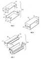
- FIG. 3is an exploded perspective view depicting an embodiment of a multi-piece insulating insert.
- FIG. 4is a perspective view depicting an embodiment of a one-piece insulating insert.
- FIG. 6is a perspective view depicting the shielding body depicted in FIG. 5 in an assembled configuration.
- FIG. 7is an exploded perspective view depicting an embodiment of an insulating insert having shut-off surfaces.
- the shielded cable assembly 10includes a shielded connector assembly 15 electrically connected to a first end 21 of a shielded cable 20 .
- the shielded cable assembly 10may have another connector assembly, such as another shielded connector assembly 15 , electrically connected at a second end thereof.
- the shielded connector assembly 15includes a connector body 25 having an insulating cover 30 formed thereon.
- An over-molding operationis one example of a suitable technique for forming the insulating cover 30 on the connector body 25 .
- the connector body 25includes a plurality of contacts members 35 attached thereto.
- a connector assemblycomprises the connector body 25 and the plurality of contact members 35 .
- the shielded connector assembly 15includes an insulating insert 55 .
- the wire attachment portion 40 of each one of the contact members 35 and the adjacent portion of each attached insulated wire 50are positioned in a wire-receiving region 60 of the insulating insert 55 .
- a cavity defined by the insulating insertis an example of the wire-receiving region 55 .
- the insulating insert 55is made from a non-conductive material such as a polymeric material. Nylon, polyethylene, polypropylene, and polyester are examples of suitable polymeric materials.
- the insulating insert 60may be formed using a technique such as injection molding, extrusion, or any other suitable manufacturing technique.
- the shielded connector assembly 15includes a shielding body 65 for limiting adverse affects of electromagnetic interference (EMI).
- the shielding body 65covers at least a portion of the connector body 25 and at least a portion of the insulating insert 55 . It is advantageous for the shielding body 65 to cover a significant portion of the connector body 25 and the insulating insert 55 . In this manner, the potential for adverse affects associated with EMI is reduced.
- the first insulating member 56includes a first alignment member 61 that is received by a first mating alignment feature 61 ′ of the second insulating member 56 .
- the first insulating member 56includes a second alignment member 62 that is received by a second mating alignment feature 62 ′ of the second insulating member 56 .
- the alignment members 61 , 62 and the respective mating alignment features 61 ′, 62 ′aid in maintaining alignment of the first insulating member 56 with the second alignment member 57 .
- the shielding body 65includes a first shielding member 66 and a second shielding member 67 .
- the first and the second shielding members 66 , 67include respective cable grounding straps 68 , 69 , respective connector shielding portions 70 , 71 and respective wire shielding portions 72 , 73 .
- the cable grounding straps 68 , 69are electrically connected to a shielding layer of the shielded cable 20 , FIG. 1, for providing electrical continuity between the shielding body 65 and the shielding layer of the shielded cable 20 .
- the shut-off interface 80is advantageous as it limits the flow of material into the wire-receiving region 60 , FIG. 2, of the insulating insert 55 during formation of the insulating cover 30 .
- the material that forms the insulating cover 30is under extremely high pressure. Accordingly, it is desirable to limit the flow of the material that forms the insulating cover 30 into the wire-receiving region 60 such that the potential for shorting of the contact members 35 and/or damaging the electrical connections at the wire attachment portion 40 is reduced.
- FIG. 9An embodiment of a method for forming the shielded cable assembly 10 is depicted in FIG. 9 .
- An operation 100is performed for attaching wires of a shielded cable to contacts of a connector assembly.
- An operation 105is performed for mounting an insulating insert over the wires of the cable and over a wire attachment region of the connector body.
- An operation 110is then performed for mounting a shielding body over the insulating insert and, in at least one embodiment, over at least a portion of the connector body.
- An operation 115is performed for establishing electrical continuity between the shielding body and a shielding layer of the shielded cable.
- An operation 120is then performed for forming the insulating cover.
- a commercially available 50 -position connector and commercially available shielding bodyare examples of the connector body 25 and the shielding body 65 , respectively.
- a CHAMP brand connector kit from Amp Incorporatedincludes a suitable commercially available connector and a suitable commercially available shielding body for fabrication a shielded connector assembly as disclosed herein.
- a suitable insulating insertmay be fabricated using a process such as injection molding.
- a commercially available shielded cablesuch as a 25-pair shielded cable from Prestolite Wire Corporation, is an example of the shielded cable 20 .
- a low-profile shielding bodyis used in constructing a low-profile shielded connector assembly.
- a low-profile shielding bodyhas at least one reduced dimension relative to a conventional profile shielding body. Reducing the height and/or overall size of the shielding body enables a low profile shielded connector assembly to be provided. However, reducing the height and/or overall size of the shielding body also reduces the clearance between the shielding body, contact members of the connector assembly, and wires connected to the contact members. In a conventional shielded connector assembly, the shielding body often deforms and/or moves during formation of the insulating cover, resulting in damage and/or shorting of the wires, contact members and electrical connections formed therebetween.
- the insulating insert disclosed hereinadvantageously reduces the potential for damage or shorting of the wires and contacts of the connector assembly.
Landscapes
- Details Of Connecting Devices For Male And Female Coupling (AREA)
Abstract
Description
Claims (32)
Priority Applications (3)
| Application Number | Priority Date | Filing Date | Title |
|---|---|---|---|
| US09/812,080US6409542B1 (en) | 2001-03-19 | 2001-03-19 | Electrically shielded connector with over-molded insulating cover |
| US09/989,344US6709292B1 (en) | 2001-03-19 | 2001-11-20 | Communication equipment shelf system and shielded cable assembly for use in same |
| US10/164,135US20020151217A1 (en) | 2001-03-19 | 2002-06-04 | Electrically shielded connector with over-molded insulating cover |
Applications Claiming Priority (1)
| Application Number | Priority Date | Filing Date | Title |
|---|---|---|---|
| US09/812,080US6409542B1 (en) | 2001-03-19 | 2001-03-19 | Electrically shielded connector with over-molded insulating cover |
Related Child Applications (2)
| Application Number | Title | Priority Date | Filing Date |
|---|---|---|---|
| US09/989,344Continuation-In-PartUS6709292B1 (en) | 2001-03-19 | 2001-11-20 | Communication equipment shelf system and shielded cable assembly for use in same |
| US10/164,135ContinuationUS20020151217A1 (en) | 2001-03-19 | 2002-06-04 | Electrically shielded connector with over-molded insulating cover |
Publications (1)
| Publication Number | Publication Date |
|---|---|
| US6409542B1true US6409542B1 (en) | 2002-06-25 |
Family
ID=25208423
Family Applications (3)
| Application Number | Title | Priority Date | Filing Date |
|---|---|---|---|
| US09/812,080Expired - LifetimeUS6409542B1 (en) | 2001-03-19 | 2001-03-19 | Electrically shielded connector with over-molded insulating cover |
| US09/989,344Expired - LifetimeUS6709292B1 (en) | 2001-03-19 | 2001-11-20 | Communication equipment shelf system and shielded cable assembly for use in same |
| US10/164,135AbandonedUS20020151217A1 (en) | 2001-03-19 | 2002-06-04 | Electrically shielded connector with over-molded insulating cover |
Family Applications After (2)
| Application Number | Title | Priority Date | Filing Date |
|---|---|---|---|
| US09/989,344Expired - LifetimeUS6709292B1 (en) | 2001-03-19 | 2001-11-20 | Communication equipment shelf system and shielded cable assembly for use in same |
| US10/164,135AbandonedUS20020151217A1 (en) | 2001-03-19 | 2002-06-04 | Electrically shielded connector with over-molded insulating cover |
Country Status (1)
| Country | Link |
|---|---|
| US (3) | US6409542B1 (en) |
Cited By (7)
| Publication number | Priority date | Publication date | Assignee | Title |
|---|---|---|---|---|
| US20040008696A1 (en)* | 2002-04-15 | 2004-01-15 | Marcoux Matthew J. | DSO timing source transient compensation |
| US6709292B1 (en)* | 2001-03-19 | 2004-03-23 | Alcatel | Communication equipment shelf system and shielded cable assembly for use in same |
| WO2005067107A1 (en)* | 2003-12-24 | 2005-07-21 | Hella Kgaa Hueck & Co. | Plug |
| US20060292916A1 (en)* | 2005-06-23 | 2006-12-28 | Alcatel | Electrical cable connectors, electrical cable assemblies, and methods of making same |
| US7836804B2 (en)* | 2003-08-20 | 2010-11-23 | Sd3, Llc | Woodworking machines with overmolded arbors |
| US20120071026A1 (en)* | 2010-09-19 | 2012-03-22 | Cheng Uei Precision Industry Co., Ltd. | Watertight connector |
| US9847607B2 (en) | 2014-04-23 | 2017-12-19 | Commscope Technologies Llc | Electrical connector with shield cap and shielded terminals |
Families Citing this family (5)
| Publication number | Priority date | Publication date | Assignee | Title |
|---|---|---|---|---|
| US20060274471A1 (en)* | 2005-06-03 | 2006-12-07 | Telect, Inc. | Outside plant cable pair protectors |
| US7685349B2 (en)* | 2005-06-03 | 2010-03-23 | Telect Inc. | Modules and backplanes |
| US20060274781A1 (en)* | 2005-06-03 | 2006-12-07 | Brian Allen | Single module access to a plurality of telecommunications circuits |
| US7554818B2 (en)* | 2005-06-03 | 2009-06-30 | Telect Inc. | Telecommunications module storage apparatus and method |
| CN201112825Y (en)* | 2007-06-13 | 2008-09-10 | 富士康(昆山)电脑接插件有限公司 | electrical connector |
Citations (7)
| Publication number | Priority date | Publication date | Assignee | Title |
|---|---|---|---|---|
| US4653825A (en)* | 1985-09-06 | 1987-03-31 | Amp Incorporated | Shielded electrical connector assembly |
| US4707045A (en)* | 1985-11-15 | 1987-11-17 | Amp Incorporated | Shielded microminiature multi-pin connector |
| US4786260A (en)* | 1986-06-10 | 1988-11-22 | Switchcraft, Inc. | Electrical cable assembly |
| US5055070A (en)* | 1990-08-29 | 1991-10-08 | Labinal Components And Systems, Inc. | Overmolded shielded connector |
| US5236375A (en)* | 1991-05-09 | 1993-08-17 | Molex Incorporated | Electrical connector assemblies |
| US5480327A (en)* | 1994-05-24 | 1996-01-02 | The Whitaker Corporation | Electrical connector for cable |
| US6257920B1 (en)* | 1999-06-25 | 2001-07-10 | Itt Manufacturing Enterprises, Inc. | Cable retention clip |
Family Cites Families (1)
| Publication number | Priority date | Publication date | Assignee | Title |
|---|---|---|---|---|
| US6409542B1 (en)* | 2001-03-19 | 2002-06-25 | Alcatel, Societe Anonyme | Electrically shielded connector with over-molded insulating cover |
- 2001
- 2001-03-19USUS09/812,080patent/US6409542B1/ennot_activeExpired - Lifetime
- 2001-11-20USUS09/989,344patent/US6709292B1/ennot_activeExpired - Lifetime
- 2002
- 2002-06-04USUS10/164,135patent/US20020151217A1/ennot_activeAbandoned
Patent Citations (7)
| Publication number | Priority date | Publication date | Assignee | Title |
|---|---|---|---|---|
| US4653825A (en)* | 1985-09-06 | 1987-03-31 | Amp Incorporated | Shielded electrical connector assembly |
| US4707045A (en)* | 1985-11-15 | 1987-11-17 | Amp Incorporated | Shielded microminiature multi-pin connector |
| US4786260A (en)* | 1986-06-10 | 1988-11-22 | Switchcraft, Inc. | Electrical cable assembly |
| US5055070A (en)* | 1990-08-29 | 1991-10-08 | Labinal Components And Systems, Inc. | Overmolded shielded connector |
| US5236375A (en)* | 1991-05-09 | 1993-08-17 | Molex Incorporated | Electrical connector assemblies |
| US5480327A (en)* | 1994-05-24 | 1996-01-02 | The Whitaker Corporation | Electrical connector for cable |
| US6257920B1 (en)* | 1999-06-25 | 2001-07-10 | Itt Manufacturing Enterprises, Inc. | Cable retention clip |
Cited By (10)
| Publication number | Priority date | Publication date | Assignee | Title |
|---|---|---|---|---|
| US6709292B1 (en)* | 2001-03-19 | 2004-03-23 | Alcatel | Communication equipment shelf system and shielded cable assembly for use in same |
| US20040008696A1 (en)* | 2002-04-15 | 2004-01-15 | Marcoux Matthew J. | DSO timing source transient compensation |
| US7209492B2 (en) | 2002-04-15 | 2007-04-24 | Alcatel | DSO timing source transient compensation |
| US7836804B2 (en)* | 2003-08-20 | 2010-11-23 | Sd3, Llc | Woodworking machines with overmolded arbors |
| WO2005067107A1 (en)* | 2003-12-24 | 2005-07-21 | Hella Kgaa Hueck & Co. | Plug |
| US20060292916A1 (en)* | 2005-06-23 | 2006-12-28 | Alcatel | Electrical cable connectors, electrical cable assemblies, and methods of making same |
| US20120071026A1 (en)* | 2010-09-19 | 2012-03-22 | Cheng Uei Precision Industry Co., Ltd. | Watertight connector |
| US8292662B2 (en)* | 2010-09-19 | 2012-10-23 | Cheng Uei Precision Industry Co., Ltd. | Watertight connector |
| US9847607B2 (en) | 2014-04-23 | 2017-12-19 | Commscope Technologies Llc | Electrical connector with shield cap and shielded terminals |
| US10476212B2 (en) | 2014-04-23 | 2019-11-12 | Commscope Technologies Llc | Electrical connector with shield cap and shielded terminals |
Also Published As
| Publication number | Publication date |
|---|---|
| US20020151217A1 (en) | 2002-10-17 |
| US6709292B1 (en) | 2004-03-23 |
Similar Documents
| Publication | Publication Date | Title |
|---|---|---|
| JP4198342B2 (en) | Shielded cable electrical connector, connector body thereof, and method of manufacturing the electrical connector | |
| US8475206B2 (en) | Coaxial connector and method for assembling the same | |
| US10777936B2 (en) | Electrical device having a ground termination component with strain relief | |
| US6837741B2 (en) | Connector and cable positioning member of connector | |
| CN101562284B (en) | Composite electrical connector assembly | |
| US6409542B1 (en) | Electrically shielded connector with over-molded insulating cover | |
| US7064266B2 (en) | Shielded connector | |
| KR102816510B1 (en) | Electrical connector | |
| US10608382B2 (en) | Electrical connector system with alien crosstalk reduction devices | |
| US5662483A (en) | Surge voltage preventing D-sub connector | |
| US6062907A (en) | Offset ultra SCSI connector | |
| US20180261960A1 (en) | Shield connector and manufacturing method therefor | |
| CN106797092B (en) | Enhanced security serial bus connector | |
| US7108522B2 (en) | Connector assembling with side grounding pin | |
| EP2828934B1 (en) | Electrical connector having an integrated impedance equalisation element | |
| TW202232834A (en) | Mini radio frequency connector | |
| TWM613606U (en) | Mini radio frequency connector | |
| JP2007234490A (en) | Connector for coaxial cable | |
| CN113054489A (en) | Electric connector and manufacturing method thereof | |
| US7210943B1 (en) | Connector | |
| US12347976B2 (en) | Cable shielding with conductive resin | |
| US6700066B1 (en) | Cable connector assembly and method of manufacturing the cable connector assembly | |
| US11532914B2 (en) | Electrical connector having insulating body and a first shell forming insertion space and a second shell covering rear side of insulating body and a metallic plate connected with the second shell | |
| US6106334A (en) | Shielded cable connector | |
| KR102587784B1 (en) | Rf connector and method for connecting devices using same |
Legal Events
| Date | Code | Title | Description |
|---|---|---|---|
| AS | Assignment | Owner name:ALCATEL, SOCIETE ANONYME, FRANCE Free format text:ASSIGNMENT OF ASSIGNORS INTEREST;ASSIGNORS:IVEY, JAMES W., JR.;BASS, KEITH;REEL/FRAME:011919/0849;SIGNING DATES FROM 20010309 TO 20010312 | |
| AS | Assignment | Owner name:ALCATEL, SOCIETE ANONYME, FRANCE Free format text:ASSIGNMENT OF ASSIGNORS INTEREST;ASSIGNORS:IVEY, JAMES W. JR.;BASS, KEITH;REEL/FRAME:012004/0888;SIGNING DATES FROM 20010309 TO 20010312 | |
| STCF | Information on status: patent grant | Free format text:PATENTED CASE | |
| FPAY | Fee payment | Year of fee payment:4 | |
| FPAY | Fee payment | Year of fee payment:8 | |
| AS | Assignment | Owner name:CREDIT SUISSE AG, NEW YORK Free format text:SECURITY AGREEMENT;ASSIGNOR:LUCENT, ALCATEL;REEL/FRAME:029821/0001 Effective date:20130130 Owner name:CREDIT SUISSE AG, NEW YORK Free format text:SECURITY AGREEMENT;ASSIGNOR:ALCATEL LUCENT;REEL/FRAME:029821/0001 Effective date:20130130 | |
| FPAY | Fee payment | Year of fee payment:12 | |
| AS | Assignment | Owner name:ALCATEL LUCENT, FRANCE Free format text:RELEASE BY SECURED PARTY;ASSIGNOR:CREDIT SUISSE AG;REEL/FRAME:033868/0001 Effective date:20140819 | |
| AS | Assignment | Owner name:PROVENANCE ASSET GROUP LLC, CONNECTICUT Free format text:ASSIGNMENT OF ASSIGNORS INTEREST;ASSIGNORS:NOKIA TECHNOLOGIES OY;NOKIA SOLUTIONS AND NETWORKS BV;ALCATEL LUCENT SAS;REEL/FRAME:043877/0001 Effective date:20170912 Owner name:NOKIA USA INC., CALIFORNIA Free format text:SECURITY INTEREST;ASSIGNORS:PROVENANCE ASSET GROUP HOLDINGS, LLC;PROVENANCE ASSET GROUP LLC;REEL/FRAME:043879/0001 Effective date:20170913 Owner name:CORTLAND CAPITAL MARKET SERVICES, LLC, ILLINOIS Free format text:SECURITY INTEREST;ASSIGNORS:PROVENANCE ASSET GROUP HOLDINGS, LLC;PROVENANCE ASSET GROUP, LLC;REEL/FRAME:043967/0001 Effective date:20170913 | |
| AS | Assignment | Owner name:ALCATEL LUCENT, FRANCE Free format text:CHANGE OF NAME;ASSIGNOR:ALCATEL;REEL/FRAME:048329/0784 Effective date:20061130 Owner name:NOKIA US HOLDINGS INC., NEW JERSEY Free format text:ASSIGNMENT AND ASSUMPTION AGREEMENT;ASSIGNOR:NOKIA USA INC.;REEL/FRAME:048370/0682 Effective date:20181220 | |
| AS | Assignment | Owner name:PROVENANCE ASSET GROUP LLC, CONNECTICUT Free format text:RELEASE BY SECURED PARTY;ASSIGNOR:CORTLAND CAPITAL MARKETS SERVICES LLC;REEL/FRAME:058983/0104 Effective date:20211101 Owner name:PROVENANCE ASSET GROUP HOLDINGS LLC, CONNECTICUT Free format text:RELEASE BY SECURED PARTY;ASSIGNOR:CORTLAND CAPITAL MARKETS SERVICES LLC;REEL/FRAME:058983/0104 Effective date:20211101 Owner name:PROVENANCE ASSET GROUP LLC, CONNECTICUT Free format text:RELEASE BY SECURED PARTY;ASSIGNOR:NOKIA US HOLDINGS INC.;REEL/FRAME:058363/0723 Effective date:20211129 Owner name:PROVENANCE ASSET GROUP HOLDINGS LLC, CONNECTICUT Free format text:RELEASE BY SECURED PARTY;ASSIGNOR:NOKIA US HOLDINGS INC.;REEL/FRAME:058363/0723 Effective date:20211129 | |
| AS | Assignment | Owner name:RPX CORPORATION, CALIFORNIA Free format text:ASSIGNMENT OF ASSIGNORS INTEREST;ASSIGNOR:PROVENANCE ASSET GROUP LLC;REEL/FRAME:059352/0001 Effective date:20211129 |