US6407724B2 - Method of and apparatus for viewing an image - Google Patents
Method of and apparatus for viewing an imageDownload PDFInfo
- Publication number
- US6407724B2 US6407724B2US09/057,461US5746198AUS6407724B2US 6407724 B2US6407724 B2US 6407724B2US 5746198 AUS5746198 AUS 5746198AUS 6407724 B2US6407724 B2US 6407724B2
- Authority
- US
- United States
- Prior art keywords
- optical device
- image
- operative
- dynamic optical
- light
- Prior art date
- Legal status (The legal status is an assumption and is not a legal conclusion. Google has not performed a legal analysis and makes no representation as to the accuracy of the status listed.)
- Expired - Fee Related
Links
Images


Classifications
- G—PHYSICS
- G06—COMPUTING OR CALCULATING; COUNTING
- G06F—ELECTRIC DIGITAL DATA PROCESSING
- G06F3/00—Input arrangements for transferring data to be processed into a form capable of being handled by the computer; Output arrangements for transferring data from processing unit to output unit, e.g. interface arrangements
- G06F3/01—Input arrangements or combined input and output arrangements for interaction between user and computer
- G06F3/011—Arrangements for interaction with the human body, e.g. for user immersion in virtual reality
- G06F3/013—Eye tracking input arrangements
- G—PHYSICS
- G02—OPTICS
- G02B—OPTICAL ELEMENTS, SYSTEMS OR APPARATUS
- G02B27/00—Optical systems or apparatus not provided for by any of the groups G02B1/00 - G02B26/00, G02B30/00
- G02B27/0093—Optical systems or apparatus not provided for by any of the groups G02B1/00 - G02B26/00, G02B30/00 with means for monitoring data relating to the user, e.g. head-tracking, eye-tracking
- G—PHYSICS
- G02—OPTICS
- G02B—OPTICAL ELEMENTS, SYSTEMS OR APPARATUS
- G02B27/00—Optical systems or apparatus not provided for by any of the groups G02B1/00 - G02B26/00, G02B30/00
- G02B27/01—Head-up displays
- G02B27/0101—Head-up displays characterised by optical features
- G02B27/0103—Head-up displays characterised by optical features comprising holographic elements
- G—PHYSICS
- G02—OPTICS
- G02B—OPTICAL ELEMENTS, SYSTEMS OR APPARATUS
- G02B27/00—Optical systems or apparatus not provided for by any of the groups G02B1/00 - G02B26/00, G02B30/00
- G02B27/01—Head-up displays
- G02B27/017—Head mounted
- G—PHYSICS
- G02—OPTICS
- G02B—OPTICAL ELEMENTS, SYSTEMS OR APPARATUS
- G02B5/00—Optical elements other than lenses
- G02B5/18—Diffraction gratings
- G02B5/1876—Diffractive Fresnel lenses; Zone plates; Kinoforms
- G02B5/188—Plurality of such optical elements formed in or on a supporting substrate
- G02B5/1885—Arranged as a periodic array
- G—PHYSICS
- G02—OPTICS
- G02B—OPTICAL ELEMENTS, SYSTEMS OR APPARATUS
- G02B27/00—Optical systems or apparatus not provided for by any of the groups G02B1/00 - G02B26/00, G02B30/00
- G02B27/01—Head-up displays
- G02B27/0101—Head-up displays characterised by optical features
- G02B2027/0138—Head-up displays characterised by optical features comprising image capture systems, e.g. camera
- G—PHYSICS
- G02—OPTICS
- G02B—OPTICAL ELEMENTS, SYSTEMS OR APPARATUS
- G02B27/00—Optical systems or apparatus not provided for by any of the groups G02B1/00 - G02B26/00, G02B30/00
- G02B27/01—Head-up displays
- G02B27/0179—Display position adjusting means not related to the information to be displayed
- G02B2027/0187—Display position adjusting means not related to the information to be displayed slaved to motion of at least a part of the body of the user, e.g. head, eye
- G—PHYSICS
- G02—OPTICS
- G02B—OPTICAL ELEMENTS, SYSTEMS OR APPARATUS
- G02B27/00—Optical systems or apparatus not provided for by any of the groups G02B1/00 - G02B26/00, G02B30/00
- G02B27/01—Head-up displays
- G02B2027/0192—Supplementary details
- G02B2027/0198—System for aligning or maintaining alignment of an image in a predetermined direction
- G—PHYSICS
- G02—OPTICS
- G02B—OPTICAL ELEMENTS, SYSTEMS OR APPARATUS
- G02B5/00—Optical elements other than lenses
- G02B5/32—Holograms used as optical elements
- G—PHYSICS
- G03—PHOTOGRAPHY; CINEMATOGRAPHY; ANALOGOUS TECHNIQUES USING WAVES OTHER THAN OPTICAL WAVES; ELECTROGRAPHY; HOLOGRAPHY
- G03H—HOLOGRAPHIC PROCESSES OR APPARATUS
- G03H1/00—Holographic processes or apparatus using light, infrared or ultraviolet waves for obtaining holograms or for obtaining an image from them; Details peculiar thereto
- G03H1/26—Processes or apparatus specially adapted to produce multiple sub- holograms or to obtain images from them, e.g. multicolour technique
- G03H2001/2605—Arrangement of the sub-holograms, e.g. partial overlapping
- G03H2001/261—Arrangement of the sub-holograms, e.g. partial overlapping in optical contact
- G03H2001/2615—Arrangement of the sub-holograms, e.g. partial overlapping in optical contact in physical contact, i.e. layered holograms
Definitions
- This inventionrelates to a method of and apparatus for viewing an image.
- diffractive optical solutionshave turned to diffractive optical solutions. It is known that diffractive techniques can be used to simulate the effect of a lens, by reducing the profile to a kinoform (FIGS. 1 and 2) or by the use of fixed surface or volume holograms. However diffractive optics have always suffered from extreme chromatic aberration when used in full colour imaging systems. Correction methods which have included multiplexing holograms recorded with different wavelengths in a single emulsion have been suggested. Such schemes still exhibit residual crosstalk between the colour channels which makes them inappropriate for high quality imaging systems.
- a method of viewing an imagecomprising transmitting an image into an eye of an observer by means of a dynamic optical device, the dynamic optical device being operative to create a modulation in respect of at least one of phase and amplitude in light transmitted or reflected thereby, said modulation being variable from one point or spatial region in the optical device to another, and wherein the modulation at any point or spatial region can be varied by the application of a stimulus, and altering the characteristics of the dynamic optical device so that the dynamic optical device acts sequentially to direct light of different colours to the observer's eye.
- the expression “transmitting an image”is intended to include the formation of a virtual aerial image at some point, or the projection of a real image onto the surface of the observer's retina.
- apparatus for viewing an imagecomprising a dynamic optical device, the dynamic optical device being operative to create a modulation in respect of at least one of phase and amplitude in light transmitted or reflected thereby, said modulation being variable from one point or spatial region in the optical device to another, and control means operative to apply a stimulus to the dynamic optical device, whereby the modulation at any point or spatial region can be varied, the control means being operative to alter periodically the characteristics of the dynamic optical device so that the device acts sequentially to direct light of different colours to the observer's eye.
- the dynamic optical devicecan comprise a succession of layers which are configured to act upon the primary wavelengths, respectively, or the different colour channels may all be embodied in the one layer of the dynamic optical device.
- optical power(focal length), size, position and/or shape of the exit pupil and other optical parameters can also be controlled.
- the above-described method and apparatusallow the provision not only of a relatively wide field of view, but also a large exit pupil, a movable exit pupil of variable shape, and high resolution.
- the dynamic optical devicecomprises a spatial light modulator containing an array of switchable elements in which the optical state of each element can be altered to create a change in phase and/or amplitude in the light incident thereon.
- the dynamic optical devicecan comprise an array of switchable prerecorded holographic elements, wherein more complex phase functions can be encoded within the holograms.
- the dynamic optical devicecan also comprise non-switchable holographic elements.
- the dynamic optical devicecomprises an electrically switchable holographic composite.
- the dynamic optical deviceis used in a range in which the phase and/or amplitude modulation varies substantially linearly with applied stimulus.
- the dynamic optical deviceis preferably used in a range in which it does not substantially affect the amplitude and/or wavelength characteristics of the light transmitted or reflected thereby.
- the dynamic optical devicecan be in the form of a screen adapted for mounting close to the observer's eye.
- the screencan be of generally curved section in at least one plane. Alternatively, for ease of manufacture, the screen may be planar.
- the apparatusalso comprises means for engaging the screen with the observer's head in a position such that the curve thereof is generally centred on the eye point.
- the dynamic optical deviceacts upon light transmitted therethrough, and the image generator is located on a side of the dynamic optical device remote from the intended position of the observer's eye.
- the dynamic optical deviceacts upon light reflected thereby, and the image generator is at least partially light-transmitting and is located between the dynamic optical device and the intended position of the observer's eye.
- the apparatusmay include image generation means configured off-axis from the general direction of the observer's eye in use.
- the image generation meanscan be non-light transmitting.
- the dynamic optical devicecomprises a plurality of discrete optical elements in close juxtaposition to each other, each of which acts as an individual lens or mirror. Conveniently, some of the discrete optical elements act to direct to the observer's eye light of one colour, while others of the discrete optical elements act to direct to the observer's eye light of other colours.
- the apparatusmay comprise left and right image generation means, left and right dynamic optical devices and left and right side portions within which said left and right image generation means are housed, said left and right image generation means being operative to project towards said left and right dynamic optical devices respectively, thereby displaying a binocular image.
- the apparatuscan also be arranged to provide for the full range of accommodation and convergence required to simulate human vision, because the parameters governing the factors can be altered dynamically.
- the dynamic optical devicefunctions to correct aberrations and/or distortions in the image produced by the image generator.
- the dynamic optical devicecan also function to create a desired position, size and/or shape for the exit pupil.
- the methodmay further comprise the steps of controlling the characteristics of the dynamic optical device to create an area of relatively high resolution in the direction of gaze of the observer's eye, the dynamic optical device providing a lesser degree of resolution of the image elsewhere, and sensing the direction of gaze of the observer's eye and altering the characteristics of the dynamic optical device in accordance therewith, so that the area of relatively high resolution is repositioned to include said direction of gaze as the latter is altered.
- the apparatusmay further comprise sensing means operative to sense the direction of gaze of the observer's eye, and the control means being operative on the dynamic optical device to create an area of relatively high resolution in said direction of gaze, the dynamic optical device providing a lesser degree of resolution of the image elsewhere, the control means being responsive to the sensing means and being operative to alter the characteristics of the dynamic optical device to move said area of relatively high resolution to follow said direction of gaze as the latter is altered.
- apparatus for viewing an imagecomprising a dynamic optical device, the dynamic optical device being operative to create a modulation in respect of at least one of phase and amplitude in light transmitted or reflectual thereby by means of which the observer's eye views an image in use, sensing means operative to sense the direction of gaze of the observer's eye, and control means which acts on the dynamic optical device to create an area of relatively high resolution in said direction of gaze, the dynamic optical device providing a lesser degree of resolution of the image elsewhere, the control means being responsive to the sensing means and being operative to alter the characteristics of the dynamic optical device to move said area of relatively high resolution to follow said direction of gaze as the latter is altered.
- the sensing meansutilises radiation which is scattered from the observer's eye and which is detected by detector means, and the dynamic optical device may also function to project said radiation onto the eye and/or to project to the detector means the radiation reflected by the eye.
- the sensing meansincludes a plurality of sensors adapted to sense the attitude of the observer's eye, the sensors being positioned in or on the dynamic optical device and/or the image generator.
- the sensing meanscomprises emitter means operative to emit radiation for projection onto the observer's eye and detector means operative to detect radiation reflected back from the eye.
- the sensing meansutilises infra-red radiation.
- the dynamic optical devicecan be reconfigured to handle visible light on the one hand and infra-red radiation on the other.
- the apparatuscan further comprise at least one optical element provided in tandem with the dynamic optical device, which acts upon infra-red light but not upon visible light.
- the detector meanscan be provided on a light-transmitting screen disposed between the image generator and the dynamic optical device.
- a reflectoris disposed between the image generator and the light-transmitting screen, and is operative to reflect the infra-red radiation whilst allowing transmission of visible light, such that the infra-red radiation after reflection by the observer's eye passes through the dynamic optical device and the light-transmitting screen, and is reflected by said reflector back towards the screen.
- the sensing meansoperates on infra-red principles, it is necessary to focus onto the detectors the returned infra-red radiation after reflection from the observer's eye.
- the same optical elementsas are used to focus the image light onto the observer's eye, the disparity in wavelength between visible light and infra-red radiation means that this cannot always be achieved effectively.
- the sensing functionis performed not by infra-red radiation but rather by means of visible light. The light can be rendered undetectable by the observer by using it in short bursts.
- the wavelength of the lightcan be matched to the colour of the surrounding elements in the image.
- the lightcan be in a specific narrow band of wavelengths. This technique also has applicability to viewing apparatus other than that including dynamic optical devices, and has a general application to any apparatus where eye tracking is required.
- the emitter means and/or the detector meansare provided on a light-transmitting screen disposed between the image generator and the dynamic optical device.
- the image generatoris in the form of a display screen, and the emitter means and/or the detector means are provided in or on the display screen.
- the emitter meansare provided in or on the display screen, a beamsplitter device is disposed between the display screen and the dynamic optical device and is operative to deflect radiation reflected by the observer's eye laterally of the main optical path through the apparatus, and the detector means are displaced laterally from the main optical path.
- the emitter means and/or detector meanscan be provided at pixel level within the field of view.
- the image generator and the dynamic optical deviceare incorporated into a thin monolithic structure, which can also include a micro-optical device operative to perform initial bean shaping.
- the monolithic structurecan also include an optical shutter switchable between generally light-transmitting and generally light-obstructing states.
- the apparatuscan further comprise means to permit the viewing of ambient light from the surroundings, either separately from or in conjunction with the image produced by the image generator.
- the image generatorcan include discrete light-emitting elements (such as lasers or LEDs) which are located on a generally light-transmitting screen through which the ambient light can be viewed.
- the light-emitting elements of said deviceare located at the periphery of said screen, and the screen acts as a light guide member and includes reflective elements to deflect the light from the light-emitting elements towards the dynamic optical element.
- the image generatoris in the form of a display panel, and the panel is mounted so as to be movable between a first position in which it confronts the dynamic optical device and a second position in which it is disposed away from the dynamic optical device.
- the image generatoris in the form of a display screen and displays an input image
- the apparatusfurther comprises detector means operative to sense the ambient light, a processor responsive to signals received from the detector means to display on the display screen an image of the surroundings, and means enabling the display screen to display selectively and/or in combination the input image and the image of the surroundings.
- the image generatorcomprises an array of light-emitting elements each of which is supplied with signals representing a respective portion of the image to be viewed, wherein the signals supplied to each light-emitting element are time-modulated with information relating to the details in the respective portion of the image, and the area of relatively high resolution is produced by means of the dynamic optical device switching the direction of the light from the light-emitting elements in the region of the direction of gaze of the observer's eye.
- the apparatuscan further comprise tracking means operative to track the head positions of a plurality of observers, and a plurality of sensing means each of which is operative to detect the direction of eye gaze of a respective one of the observers, with the dynamic optical device being operative to create a plurality of exit pupils for viewing of the image by the observers, respectively.
- the image produced by the image generatorcan be pre-distorted to lessen the burden on the dynamic optical device.
- the distinction between the image display and the dynamic optical deviceis less well defined, and the functions of the image generator and the dynamic optical device can be combined into a single device, such as a dynamic hologram.
- a spatial light modulatorcan be used to produce a dynamic diffraction pattern which is illuminated by one or more reference beams.
- said image for viewing by the observeris displayed on a display screen, which can be of generally curved section in at least one plane.
- the apparatuscan further comprise means for engaging the display screen with the observer's head in a position such that the curve thereof is generally centred on the eye point.
- the apparatuscan form part of a head-mounted device.
- the dynamic optical devicefunctions not only to focus image light onto the observer's eye, but also to project radiation from the emitters onto the eye, and/or to project the radiation reflected by the eye onto the detectors.
- this general techniquecan be applied to viewing apparatus in which conventional optics rather than a dynamic optical device are employed.
- viewing apparatuscomprises an image generator operative to generate an image for viewing by an observer's eye, an optical system for transmitting said image to the observer's eye position, sensing means operative to sense the direction of gaze of the observer's eye, and control means responsive to the sensing means and operative to act on the image generator and/or the optical system to modify said image transmitted to the eye in accordance with the direction of gaze of the eye, the sensing means including emitter means operative to emit radiation for projection onto the observer's eye, and detector means operative to detect said radiation after reflection by said eye, the optical system also functioning to transmit said radiation from the emitter means onto said eye and/or to transmit said radiation reflected from said eye to the detector means.
- said radiationcomprises infra-red radiation.
- the optical systemincludes at least one optical element which acts upon both visible light and infra-red radiation, and at least one second optical element which acts upon infra-red radiation but not upon visible light.
- the optical systemcan have a different focal length for visible light than that for infra-red radiation.
- the detector means(and preferably also the emitter means) are provided on a light-transmitting screen disposed between the image generator and the optical system.
- a reflectorsuch as a holographic/diffractive reflector or a conventional dichroic reflector
- a reflectoris disposed between the image generator and the light-transmitting screen, and is operative to reflect the infra-red radiation whilst allowing transmission of visible light, such that the infra-red radiation after reflection by the observer's eye passes through the optical system and the light-transmitting screen, and is reflected by said reflector back towards the screen.
- the emitter means and/or the detector meanscan be provided in or on the display screen.
- the emitter meanscan be provided in or on the display screen
- a beamsplitter devicecan be disposed between the display screen and the optical system so as to deflect infra-red radiation reflected by the observer's eye and passing through the optical system laterally of the main optical path through the apparatus, and the detector means can be displaced laterally from said main optical path.
- the image generatorgenerates a pixellated image, and the emitter means and/or the detector means are provided at pixel level.
- the sensing meanscomprises emitters and detectors provided at pixel level within the field of view. According to a fourth aspect of the present invention, this general technique can be applied to viewing apparatus in which conventional optics rather than a dynamic optical device are employed.
- viewing apparatuscomprises an image generator operative to generate an image for viewing by an observer's eye, an optical system for transmitting said image to the observer's eye position, sensing means operative to sense the direction of gaze of the observer's eye, and control means responsive to the sensing means and operative to act on the image generator and/or the optical system to modify said image transmitted to the eye in accordance with the direction of gaze of the eye, the sensing means including emitter means operative to emit radiation for projection onto the observer's eye, and detector means operative to detect said radiation after reflection by said eye, the emitter means and/or the detector means being provided at pixel level within the field of view of the image.
- the emitter means and/or the detector meanscan be provided at pixel level in or on the display screen.
- the emitter means and/or the detector meanscan be provided at pixel level on a light-transmitting screen disposed between the image generator and the optical system.
- said radiationcomprises infra-red radiation.
- the optical systemincludes at least one optical element which acts upon both visible light and infra-red radiation, and at least one second optical element which acts upon infra-red radiation but not upon visible light.
- the optical systemcan have a different focal length for visible light than that for infra-red radiation.
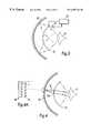
- FIG. 1is a schematic view of a kinoform lens of known type
- FIG. 2is a graphical arrangement of a kinoform lens, demonstrating how the lens can be implemented in practice
- FIG. 3is a general arrangement drawing illustrating a viewing apparatus and method according to the present invention.
- FIG. 4is a schematic view of a first embodiment of viewing apparatus according to the present invention.
- FIG. 4Ais a detail of part of the apparatus shown in FIG. 4;
- FIGS. 4B to 7are graphs illustrating various characteristics of the apparatus of FIG. 4;
- FIG. 8is a schematic view of a modification to the first embodiment of the viewing apparatus
- FIG. 8Ais a detail of part of the apparatus shown in FIG. 8;
- FIG. 9is a schematic view of a second embodiment of viewing apparatus according to the present invention.
- FIG. 10is a schematic view of a modification to the second embodiment of the viewing apparatus.
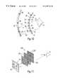
- FIG. 11illustrates a third embodiment of viewing apparatus according to the invention, which uses an electrically switchable holographic composite (ESHC);
- ESHCelectrically switchable holographic composite
- FIGS. 11A and 11Billustrate the operation of the ESHC
- FIGS. 12 and 13illustrate the use of an alternative form of image generator in the apparatus
- FIGS. 14 and 15show arrangements enabling the viewing of the surroundings in addition to a displayed image
- FIGS. 16 to 18are schematic views of further embodiments of viewing apparatus according to the invention, showing in particular an eye tracker;
- FIG. 19is a diagram illustrating the general principle of a dynamic optical device as embodied in the viewing apparatus.
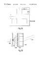
- FIG. 20is a diagram illustrating the use of a dynamic hologram
- FIGS. 21 and 21Aillustrate the use of planar display screens and dynamic optical devices
- FIG. 22is an exploded perspective view of apparatus for viewing an image, employing an ESHC as the dynamic optical device;
- FIG. 23is a schematic section through the apparatus shown in FIG. 22;
- FIG. 24is a schematic sectional view of an arrangement wherein the apparatus is of generally curved configuration
- FIG. 25is a schematic sectional view of another embodiment of the apparatus.
- FIG. 26is a schematic sectional view of part of an image generator
- FIGS. 27A, 27 B and 27 Care schematic views of different optical arrangements for the apparatus
- FIG. 28is a schematic view of apparatus for use by multiple observers
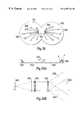
- FIGS. 29 and 30are schematic plan views of apparatuses for use in displaying stereoscopic images
- FIGS. 31 to 35show a further embodiment of viewing apparatus according to the present invention.
- FIGS. 36. 36A and 36 Bshow a modification of the embodiment depicted in FIGS. 31 to 35 .
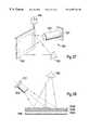
- FIG. 37is a perspective schematic diagram of a further specific embodiment of apparatus in accordance with the invention.
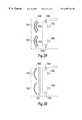
- FIG. 38is a plan view of the apparatus illustrated in FIG. 37;
- FIG. 39is a plan view of a yet further specific embodiment of apparatus in accordance with the invention.
- FIG. 40is a view of the dynamic optical device of the apparatus illustrated in FIG. 39, in use, in the direction indicated by arrows X in FIG. 39 ;
- FIG. 3there is shown a general arrangement of viewing apparatus which comprises a display screen 10 on which is displayed an image to be viewed by an eye 11 of an observer. Interposed between the display screen 10 and the eye 11 is a dynamic optical element (in this case, a lens) in the form of a screen 12 .
- the dynamic lenscomprises a spatial light modulator (such as a liquid crystal device) to which a stimulus is applied by a control device 13 to create an area of relatively high resolution in the direction of gaze of the eye 11 , the remaining area of the modulator providing a lesser degree of resolution.
- a spatial light modulatorsuch as a liquid crystal device
- Sensing means 14is operative to sense the attitude of the eye 11 , and the control device 13 is responsive to signals received from the sensing means 14 and alters the characteristics of the modulator so that the area of relatively high resolution is moved so as to follow the direction of gaze of the observer's eye 11 as this is altered.
- the apparatusin the ensuing description, reference will be made to the apparatus as being applied to one of the observer's eyes. However, when used for virtual reality applications, two such apparatuses will in fact be provided, one for each eye. In this case, the respective display screens can (if desired) be used to display stereoscopic images to provide a 3-D effect to the observer.
- FIGS. 4 and 4Ashow a first actual embodiment of the viewing apparatus, wherein similar components are designated by the same reference numerals as used in FIG. 3 .
- the control device 13 and the sensing means 14are omitted for the sake of clarity.
- the display screen 10 and the screen 12are each of curved configuration and are centred generally on the rotation axis of the observer's eye 11 .
- the spatial light modulator comprising the screen 12can operate on phase and/or amplitude modulation principles. However, phase modulation is preferred because amplitude modulation devices tend to have relatively low light efficiency.
- the modulatorhas a phase modulation depth of not less than 2 and its phase shift varies linearly with applied voltage.
- the aperture and focal length of the dynamic lens formed by the spatial light modulatorare dictated by the resolution of the modulator.
- the form of the lensis modified in real time, allowing the focal length to be changed so that conflicts between accommodation and convergence can be resolved.
- focus correction for different userscan be carried out electronically rather than mechanically.
- the dynamic lensis intended to provide an area of interest (AOI) field of view, the AOI being a high resolution region of the field of view that corresponds to the instantaneous direction of gaze of the observer's eye.
- AOIarea of interest
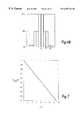
- FIG. 4Bshows in graphic form the variation of resolution across the AOI.
- the optics required to achieve human visual fields of viewinvolve very complex optical designs consisting of many separate lens elements.
- the concept employed in the present inventionachieves economy of design by using an adaptive lens in which its transform is recomputed for each resolution cell of the field of view.
- the dynamic lensis used with a device (eye tracker) which senses the attitude of the observer's eye, only a modest AOI is required. Accordingly, the form of the lens is simplified, although separate lens forms are required for each increment in the field of view to ensure that collimation is preserved over the entire field of view.
- the diffractive principles employed by the spatial light modulatorare ideally suited to correcting for monochromatic aspheric and high order spherical aberrations, distortion, tilt and decentring effects.
- diffractive structuressuffer from chromatic aberration, it is necessary to compute separate forms for each wavelength, and in particular to re-compute the diffraction pattern for each of the primary wavelengths used in the display.
- the dynamic optical deviceis configured to produce an array of discrete micro-lenses in close juxtaposition to each other, with some of the micro-lenses acting to direct to the observer's eye red light, whilst other micro-lenses act to direct green and blue light to the observer's eye, respectively.
- the characteristics of the dynamic optical deviceare altered periodically so that, at least in the area of high resolution, it acts to direct to the observer's eye red, green and blue light in temporal sequence.
- the dynamic optical devicecomprises several layers which are designed to act on red, green and blue wavelengths, respectively.
- the resolution of the apparatusis dependent upon several factors, especially the dimensions of the dynamic lens, the resolution of the spatial light modulator, the number of phase levels in the spatial light modulator, focal length and pixel size of the display screen 10 .
- the dynamic lensis operated not as a single lens, but rather as an array of micro-lenses as depicted schematically at 12 a in FIG. 4 .
- Diffracting structuresare subject to similar geometric aberrations and distortions to those found in conventional lenses.
- an eye trackerin conjunction with an area of high resolution in the dynamic lens, the effects of distortion are minimal, particularly since low relative apertures are used.
- diffractive opticsare more difficult to correct at high optical powers. From basic aberration theory, the field angle achievable with the dynamic lens is limited to a few degrees before off-axis aberrations such as coma start to become significant and it becomes necessary to re-compute the diffraction pattern.
- the correction of geometric distortions and matching of the AOI with lower resolution background imagerycan be carried out electronically.
- the dynamic lensis implemented in a curved configuration (as depicted in FIG. 4 )
- the effects of geometric distortionwill be minimal.
- FIG. 4Ashows a detail of the display screen 10 depicted in FIG. 4, wherein an array 15 of micro-lenses is disposed in front of the display screen 10 to perform initial beam-shaping on the light emitted from the screen, before this is transmitted to the dynamic lens.
- this beam-shaping functioncan be performed by means of diffractive or holographic components.
- the eye trackeris arranged to operate at bandwidths of at least 1000 Hz in order to determine the tracking mode of the eye (for example smooth pursuit or saccade).
- FIG. 5shows in graphic form a calculation of the number of resolution cells in the exit pupil that will need to be up-dated per frame as a function of the AOI for different values of the dynamic lens field angle.
- the dynamic lensconsists of 20 ⁇ 20 micro-lenses each of 0.5 mm size, with each micro-lens having a resolution of 48 ⁇ 48. It has also been assumed that the dynamic lens has a field of view of 7°, and that the AOI is 10°.
- the specification of the input image display(i.e. the image as displayed on the screen 10 ) will be determined by the required display resolution. For example, by aiming to match the 1 minute of arc resolution of the human visual system, the display will need to provide a matrix of 8100 ⁇ 8100 pixels to achieve the desired performance over a field of view of 135° ⁇ 180°. The number to be up-dated in any given frame will be considerably smaller.
- FIG. 6shows in graphic form the number of active display elements required in the exit pupils, assuming a variable resolution profile of the form shown in FIG. 7 .
- the exit pupil of the dynamic lensis not subject to the same physical constraints as that of a conventional lens system, since it is defined electronically. According to the normal definition of the term, it could be said that the exit pupil covers the whole of the 135° ⁇ 180° field of view. However, because of the eye tracking function employed in the present invention, it is more appropriate to consider the exit pupil as being the region of the spatial light modulator array contained within the eye-tracked area of interest. The remainder of the field of view is filled with imagery whose resolution progressively decreases as the periphery is approached.
- FIG. 8illustrates a particular manner of implementing the eye tracking function, with similar components being accorded the same reference numerals as employed in FIG. 4 .
- the eye tracking functionis achieved by means of an array of emitters 17 and detectors 18 provided on a screen 19 disposed immediately in front of the display screen 10 .
- Radiation(such as infra-red radiation) is emitted by the emitters 17 and is directed by the dynamic lens 12 as a broad wash across the observer's eye 11 , as depicted by arrows 20 .
- the radiation reflected by the eye 11is then focussed by the dynamic lens 12 onto the detectors 18 , as depicted by arrows 21 .
- the dynamic lens 12not only functions to transmit to the observer's eye the image as displayed on the screen 10 , but also forms an important part of the eye-tracker.
- the spatial frequencies of the emitters 17 and detectors 18do not have to be very high, but are sufficient to resolve the eye of the pupil or some other ocular parameter.
- FIG. 9shows an alternative embodiment in which the dynamic optical element takes the form of a mirror 22 rather than a lens.
- the display screen 10is interposed between the dynamic mirror 22 and the observer's eye, and is formed by a generally light-transmitting screen 23 on which are provided a series of visible light emitters 24 (such as LEDs, lasers or phosphors) in red-green-blue triads.
- the triadsare spaced apart from one another, to permit the eye 11 to view the displayed image after reflection by the dynamic mirror 22 and subsequent passage through the screen 23 .
- Each triadis fronted by a micro-lens array 25 which performs initial beam shaping.
- the dynamic mirror 22is based on the same diffractive optical principles as the dynamic lens.
- the use of reflection techniquescan offer some advantages over a transmissive mode of operation because the drive circuitry for the spatial light modulator can be implemented in a more efficient way, for example on a silicon backplane.
- the limited resolution of currently available spatial light modulatorswill dictate that the mirror 22 is made up of an array of miniature dynamic mirrors, each comprising a separate diffracting array.
- the display screen 10By arranging for the display screen 10 to have a suitably high pixel resolution, the displayed area of interest image can be built up by generating a different field of view element for each pixel, in a similar way to a dynamic lens.
- the imagecan be generated by modulating the emitters 24 and synchronously modifying the diffracting patterns contained in the mirror 22 in such a way that the required image is produced by switching the direction of the emitted light in the field of view.
- Thishas the advantage of requiring fewer elements in the partially transmitting panel 23 and hence allowing a higher transmission.
- An equivalent approachcan also be used in the case where the dynamic optical element is a lens.
- FIG. 10illustrates the application of the eye tracker to apparatus of the type shown in FIG. 9 .
- emitters 26 of radiationsuch as infra-red light
- the mirror 22then reflects that radiation as a broad wash through the screen 23 and onto the observer's eye 11 , as depicted by arrows 27 .
- Radiation reflected by the eye 11passes back through the screen 23 and onto detectors 28 provided on the mirror 22 .
- Other configurationsare, however, possible.
- both the emitters 26 and detectors 28could be mounted on the panel 23 , with the dynamic mirror performing the functions of receiver and transmitter optics.
- spatial light modulatorcomprising a liquid crystal device.
- other types of spatial light modulatorcan also be used, such as surface acoustic wave devices and micro-mirror arrays.
- the dynamic optical device 12takes yet another form, namely that of an electrically switchable holographic composite (ESHC).
- ESHCelectrically switchable holographic composite
- Such a composite(generally referenced 200 ) comprises a number of layers 201 , each of which contains a plurality of pre-recorded holographic elements 202 which function as diffraction gratings (or as any other chosen type of optical element).
- the elements 202can be selectively switched into and out of operation by means of respective electrodes (not shown), and sequences of these elements 202 can be used to create multiple diffraction effects.
- ESHCshave the advantages of high resolution, high diffraction efficiency, fast switching time and the capability of implementation in non-planar geometries.
- ESHCshave sub-micron resolution, which represents a substantially higher pixel density than that of the above-described types of spatial light modulators.
- the resolution of conventional spatial light modulatorsare of the order of 512 2 , representing about one million bits of encoded data: the diffraction efficiencies tend to be well below 50%.
- ESHCsoffer a resolution equivalent to 10 13 bits, and diffraction efficiencies close to 100% are therefore a practical proposition.
- An ESHCmay be defined as a holographic or diffractive photo polymeric film that has been combined with a liquid crystal.
- the liquid crystalis preferably suffused into the pores of the film, but can alternatively be deposited as a layer on the film.
- the hologrammay be recorded in the liquid crystal either prior to or after the combination with the photo polymeric film. Recordal of the hologram can be performed by optical means, or by the use of highly accurate laser writing devices or optical replication techniques.
- the resultant compositetypically comprises an array of separate holograms that are addressed by means of an array of transparent electrodes manufactured for example from indium tin oxide, which usually have a transmission of greater than 80%.
- the thickness of the compositeis typically 10 microns or less.
- Application of electric fields normal to the plane of the compositecauses the optical characteristics of the liquid crystals to be changed such that the diffraction efficiency is modulated.
- the liquid crystalis initially aligned perpendicularly to the fringe pattern and, as the electric field is increased, the alignment swings into the direction with the effective refractive index changing accordingly.
- the diffraction efficiencycan be either switched or tuned continuously.
- the range of diffraction efficienciescovers the approximate range of 100% to 0.1%. There is therefore a very large range of diffraction efficiency between the “fully on” and “fully off” states of the ESHC, which makes the ESHC a very efficient switching device.
- the speed of responseis high due to the encapsulation of the liquid crystals in the micropore structure of the polymeric film.
- very high resolutionscan be achieved, with equivalent array dimensions of up to 10 5 and sub-micron spot sizes. It is even possible to approach the theoretical ideal of a continuous kinoform.
- holographic diffraction patternsmust be pre-recorded and cannot be altered, a limited degree of programmability is possible. For example, it is possible to programme diffraction efficiency and relative phase in arrays of holographic elements arranged in stacks and/or adjacent to each other.
- a multi-layer ESHC of this typeis essentially a programmable volume hologram. Taking multiple diffraction into account, a wavefront passing through the device could be switched into 2 N output wavefronts, where the integer N represents the product of the number of layers and the number of elements in each layer.
- the number of possible output wavefrontsis 2 197 (or 10 57 ).
- the number of diffractive functions that can be implementedis practically unlimited.
- some of the layers in a stackwould be provided with electrodes, whilst others would operate in a passive state.
- Each wavefrontcan be made to correspond to a particular gaze direction. Manifestly, not all of the wavefronts would be generated at the same time because of the need for certain rays to use the same holograms along portions of their paths. However, by making the hologram array sizes suitably large and taking advantage of the characteristic short switching time, the requisite number of wavefronts can be generated at typical video rates of 50 Hz.
- a holographic arraywould be required with size equivalent to:
- hologramsare highly dispersive, the effects of chromatic aberration can be minimised by arranging for separate “channels” in the ESHC for the primary wavelengths, so that each channel can be optimised for the particular wavelength concerned.
- the term “channel”is intended to indicate a sequence of holographic elements through which the beam propagates.
- chromatic aberration caused by the finite bandwidth of the light emitted by LEDscan be reduced by employing suitable band pass filters
- An ESHCis typically a thick or volume hologram which is based on Bragg diffraction, giving a theoretical diffraction efficiency of 100%.
- FIG. 11Adepicts an ESHC in which the holographic elements 202 in successive layers 201 become progressively more staggered towards the periphery. This enables light rays (such as indicated at L) to be deviated at the periphery of the ESHC through larger angles than would otherwise be possible.
- FIG. 11Bis a schematic illustration of the way in which a light beam L 1 can be deflected through differing angles by reflection at the Bragg surfaces B of the holographic elements in successive layers 201 of the ESHC.
- L 1denotes the path followed by a light beam which is deflected by a Bragg surface in the first of the layers 201 only
- L 1denotes the path followed by the same beam when the relevant holographic element in the next layer is activated so that the beam is deflected by a Bragg surface in that element also.
- the dynamic optical devicecan operates a mirror, for example by combining an ESHC device with conventional silicon backplane technology, such as is used in active matrix liquid crystal displays.
- the dynamic optical devicecan take the form of a multi-layer liquid crystal divided into a number of individual cells, each of which is switchable between a limited number of states, which creates essentially the same effect as an ESHC.
- the image for viewing by the observeris generated by a display screen, in particular an LCD screen, although an electro luminescent screen or any other flat-panel screen (eg LED array) could be used instead.
- a display screenin particular an LCD screen
- an electro luminescent screen or any other flat-panel screeneg LED array
- FIG. 12shows one particular example, in which the input image data is generated by modulating an array of light emitting elements 250 (such as lasers or LEDs) at high frequency and using an ESHC 251 as described above to “switch” the laser beams between different orientations, such as indicated for laser beam 252 .
- the lasers in the arraycan be configured as triads of red, blue and green.
- a micro-optic beam-forming systemsuch as micro lenses 253 can be associated with the lasers.
- FIG. 13shows another example of the viewing apparatus, in which the image generator takes the form of a light guide panel 260 having a series of lasers 261 disposed around its periphery. Fabricated within the panel 260 are a series of prisms 262 each of which has an inclined semi-reflecting surface 263 confronting one of the lasers 261 . These surfaces 263 receive light from the lasers 261 and partially reflect this in a direction normal to the panel 260 . Microlenses 264 are provided on a surface of the panel 260 which confronts the user, to focus and/or shape the respective laser beams.
- LEDs of suitably narrow wavelength bandscould be used.
- the lasers and/or LEDscan be fabricated from wide-band semiconductors such as GaN.
- the image informationis encoded by temporal modulation of the laser beams, and therefore the resolution of the laser array does not need to be large.
- the observercan have the facility of viewing the surroundings.
- an external shutter 270such as by means of an additional layer of liquid crystal
- the observercan switch the surroundings into and out of view.
- the observercan use the shutter to shut out external light whilst using the ESHC in diffractive mode to view a virtual display, or alternatively the shutter can be used to transmit light from the surroundings whilst switching the ESHC to non-diffractive mode.
- the virtual imagery and ambient viewcan be superimposed in the manner of a head-up display.
- the shutter liquid crystalcan be provided as an array such that it is possible to switch off those pixels corresponding to field of view directions at which virtual imagery is to be displayed.
- other techniquescan be employed, such as those based on polarisation, wavelength division, etc.
- FIG. 14A further alternative is depicted in FIG. 14, wherein the display panel (referenced 280 ) is pivotally mounted on a headset 281 of which the apparatus forms part.
- the panel 280can be pivoted between a first position (shown in broken lines) in which it confronts the dynamic lens (referenced 282 ), and a second position (shown in solid lines) in which it is disposed away from the lens 282 to allow ambient light to pass therethrough.
- FIG. 15Another arrangement is shown in FIG. 15, wherein the display panel (referenced 290 ) does not allow ambient light to pass therethrough, and in which a detector array 291 is disposed on the external side of the panel 290 so that the detectors therein face the surroundings through a panel 292 of lenses.
- the lenses in the panel 292form images of the surroundings on the detectors in the array 291 , and signals received from the detectors are processed by a processor 293 for display on the display panel 290 .
- the usercan switch the display on the panel 292 between internal imagery and the surroundings, and view either of these by way of the dynamic lens (referenced 293 ).
- the sensing meanscomprises emitters and detectors.
- the emittersemit radiation (such as infra-red radiation) which is projected as a broad wash onto the observer's eye, and the radiation scattered back from the eye is projected onto the detectors.
- the dynamic optical devicefunctions not only to focus image light onto the observer's eye, but also to project the radiation from the emitters onto the eye and/or to project the radiation reflected by the eye to the detectors.
- the emitters and/or the detectorsare provided at pixel level within the field of view of the observed image.
- FIGS. 16 and 16AOne such system is illustrated in FIGS. 16 and 16A, in which one or more infra-red emitters (referenced 300 ) are provided on a light-transmitting screen 301 positioned forwardly of the display screen 10 .
- Image light 302 from the display screen 10is directed to the observer's eye 11 by means of a lens system 303 (depicted schematically) which collimates the image light over a field of view of typically 40°.
- Infra-red radiation 304 from the emitter(s) 300is projected as a broad wash onto the surface of the eye 11 by the lens system 303 and is scattered thereby.
- the returned infra-red radiation 304 1is propagated back through the lens system 303 , and is projected onto an element 305 positioned immediately in front of the display screen 10 which acts as a reflector to infra-red wavelengths but not to visible light.
- the element 305can for example be a holographic or diffractive mirror, or a conventional dichroic mirror.
- the infra-red radiationis projected onto the screen 301 as a focussed image of the pupil of the eye 11 , and is incident upon one or more detectors 306 provided at pixel level in or on the screen 301 .
- the arrangement of the emitters 300 and detectors 306is such as to cause minimal obstruction to the passage of the image light through the screen 301 .
- FIG. 16Ashows a cross-section of the screen 301 , on which the focussed pupil image is indicated by broken lines at 307 . If (as shown) the detectors 306 are arranged in an array in the shape of a cross, then the dimensions of the instantaneous image 307 can be measured in two orthogonal directions, although other arrangements are also possible.
- FIG. 17An alternative system is shown in FIG. 17, wherein a small number of infra-red emitters 400 (only one shown) are provided at pixel level in or on the display screen 10 itself.
- image light 401 from the display screen 10is directed to the observer's eye 11 by a lens system 402 .
- an inclined beamsplitter 403is interposed between the display screen 10 and the lens system 402 .
- Infra-red radiation 404 from the emitters 400passes through the beamsplitter 403 and is projected by the lens system 402 as a broad wash onto the observer's eye 11 to be scattered thereby.
- the returned infra-red radiation 404 1passes through the lens system 402 and is then reflected by the beamsplitter 403 so that it is deflected laterally (either sideways or up or down) towards a relay lens system 405 , which projects the returned infra-red radiation onto an array of detectors 406 to form a focussed infra-red image of the pupil on the detector array.
- a relay lens system 405projects the returned infra-red radiation onto an array of detectors 406 to form a focussed infra-red image of the pupil on the detector array.
- Both the relay lens system 405 and the detector array 406are thus displaced laterally from the main optical path through the viewing apparatus.
- the beamsplitter 403takes the form of a coated light-transmitting plate, but a prism can be used instead.
- FIG. 18A further alternative arrangement is shown in FIG. 18, wherein one or more infra-red emitters 500 are again incorporated at pixel level in or on the display screen 10 .
- image light 501 from the display screen 10is focussed by a lens system 502 onto the observer's eye 11 , with the lens system 502 collimating the visible light over a field of view of typically 40°.
- the focal length of the combined optical system comprising the element(s) 503 and the lens system 502 for visible lightis different from that for infra-red radiation.
- the combined effect of the element(s) 503 and the lens system 502is to produce a broad wash of infra-red radiation across the surface of the observer's eye 11 .
- Infra-red light scattered off the surface of the eyeis then projected by the combined effect of the lens system 502 and the element(s) 503 onto the surface of the display screen 10 to form a focussed infra-red image of the pupil, which is detected by detectors 505 (only one shown) also provided at pixel level in or on the display screen 10 .
- the lens systems 303 , 402 and 502are based on conventional refractive optical elements. However, the principles described can be applied to arrangements wherein a dynamic optical device is used instead.
- the lens systems 303 , 402 and 502perform the dual function of focussing the image light onto the observer's eye and of focussing the returned infrared radiation onto the detectors.
- the lens systemmust therefore cope with a wide variation of different wavelengths, and a lens system which has optimised performance with respect to visible light may not perform exactly the desired function with respect to infra-red radiation.
- the disparityis sufficiently small that it does not create a problem, particularly if near infra-red radiation is used.
- infra-red radiationfor eye tracking
- light in the visible spectrumcould be rendered undetectable to the observer by using the light in very short bursts, or by allocating specific elements in the array for tracking (which could be colour-adjusted to match the surrounding image elements), or by using specific narrow bands of wavelengths.
- the efficiency of the eye trackerwill be limited by the latency of the processing system used to detect the variation in the ocular feature (such as the pupil edge, the dark pupil, etc) that is being used.
- the processing system used to detect the variation in the ocular featuresuch as the pupil edge, the dark pupil, etc
- parallel processing techniqueswhich can be implemented using hybrid electronic-optical technology, or even entirely optical processing methods.
- An optical computer for use with the present apparatuscomprises components such as switches, data stores and communication links.
- the processinginvolves the interaction of the dynamic lens with the emitters and detectors.
- Many different optical processing architecturesare possible, the most appropriate types being those based on adaptive networks in which the processing functions are replicated at each node. It is even possible to combine the image generator, optical computing structure and the dynamic lens into a single monolithic structure.
- a dynamic lensis a device based on diffraction principles whose optical form can be changed electronically. For example, this can take the form of a lens based on a binary profile, or a close approximation to the ideal kinoform, written onto a spatial light modulator or similar device.
- the primary use of the dynamic lensis to vary the focal length, it can also serve other functions such as to correct geometric distortions and aberrations. For example, chromatic aberrations can be reduced by re-calculating the diffraction pattern profiles (and hence the focal length) of the lens for each primary wavelength in sequence.
- three associated dynamic lensescould be used, each optimised for a different primary wavelength. These lenses can be augmented by bandpass filters operating at the primary wavelengths.
- the dynamic lensin association with an input image array
- a wide field of viewcan be created, which helps realism. This stems primarily from the ability to move the exit pupil.
- the ability to implement imaging functions within a relatively thin architecturealso helps to eliminate many of the geometrical optical obstacles to achieving high FOV displays.
- a large exit pupilis achieved either by using mechanical means to move a small exit pupil (which is generally not practical given the problems of inertia, etc), or by using large numbers of optical elements to correct aberrations, etc, with consequent complexity and expense.
- the apparatuscan be made light in weight so that it is comfortable and safe for a user to wear. This also means that the apparatus has low inertia, so the user has minimal difficulty in moving his or her head while wearing the apparatus.
- the reduction in weightresults in part from the intrinsic lightness of the materials used to fabricate the spatial light modulator, as compared with those employed for conventional optics.
- the functions of image transmission and eye trackingare combined into a single integral unit. This also assists in making the apparatus relatively low in weight. Furthermore, it also provides for easy area of interest detection and detail enrichment, which enables an effective high resolution to be achieved.
- the software for driving operation of the dynamic lensit is possible to prevent disassociation between accommodation and convergence, so that the apparatus does not place a visual strain on the user and provides a more realistic display.
- Thisis to be contrasted with conventional optics which, even if the relevant range information is available, are not capable of displaying objects at the correct depth without incorporating moving parts in the optical system or using other methods of changing the focal characteristics of the lenses.
- a further advantageous property of the dynamic lensis its ability to reconfigure itself to allow different wavelength bands (e.g. visible and infra-red) to propagate through it. Multiple wavelengths can be transmitted simultaneously, either by allocating different portions of the dynamic lens to different wavelengths, or by reconfiguring the lens sequentially for those wavelengths. Moreover, the direction of propagation of those different wavelengths does not have to be the same. This makes the dynamic lens particularly useful in on the one hand transmitting image light for viewing by the observer, and on the other hand transmitting the infrared light used in the eye tracker system.
- different wavelength bandse.g. visible and infra-red
- FIG. 19illustrates the basic concept of a dynamic lens operating on diffraction principles.
- the display screen 10embodies a number of infra-red emitters 600 at pixel level, and a series of diffraction patterns 601 are generated in a spatial light modulator 602 which serve the function of lenses, to focus image light 603 from the display screen 10 onto the observer's eye and to project the infra-red light 604 from the emitters 600 as a broad wash onto the surface of the eye 11 .
- FIG. 20illustrates a further development of the invention, in which the functions of image generation and dynamic imaging are combined within a dynamic holographic element 700 .
- the required output imageis then produced by reconstruction using only a series of reference beams produced by an array of discrete light sources 701 .
- the light sources 701are mounted on a screen 702 disposed behind the dynamic holographic element 700 , on which are also provided infra-red emitters 703 and detectors 704 for the eye tracking function.
- the screen 702thus performs no imaging function, i.e. it has no pictorial content, its purpose being merely to provide a set of reference beams.
- the resolution of the array of reference beam sources 701can in fact be quite low, although the economy of design that results is achieved at the expense of the additional computational power required to re-calculate the hologram for each image update, since both the lens function and the image need to be recomputed.
- the dynamic holographic element 700can be implemented using a high resolution spatial light modulator such as that based on liquid crystals, micro-mechanical mirror arrays or opto-acoustic devices. It is possible for the dynamic hologram to operate either in transmission or in reflection. As is the case where a separate dynamic optical device and image generator are used, the use of reflective techniques can offer certain advantages, such as in allowing circuitry to be implemented in a more efficient way, and in enhancing the brightness of the display.
- a texturised screenis provided around the periphery of the image displayed on the display screen.
- the screencan be provided as a separate component which surrounds or partially overlies the periphery of the display screen.
- a peripheral region of the display screenitself can be reserved to display an image replicating the texturised effect.
- the display screen and dynamic lensare described as being curved.
- FIGS. 21 and 21Ait is possible to construct the display screen 10 from a series of planar panels 900 , and similarly to construct the dynamic lens 12 from a series of panels 901 , each panel 900 and 901 being angled relative to its neighbour(s) so that the display screen and dynamic lens each approximate to a curve.
- FIG. 21Ashows the configuration of the screen 10 and lens 12 in three dimensions.
- the apparatuscomprises an image generator 1010 in the form of an array of LED triads 0101 provided on a generally light-transmitting screen 1012 .
- the LED triads 1011form a low resolution matrix of, say, 100 ⁇ 100 or 200 ⁇ 200 elements.
- Light from the LED triads 1011is subjected to beam shaping by a microlens array 1013 , and then passes through a liquid crystal shutter 1014 towards an ESHC 1015 .
- the microlens array 1013has as its main effect the collimation of the light emitted by the LED triads 1011 , and can be of holographic design.
- the LEDs in the triads 1011are driven by signals defining an image to be viewed by an observer.
- these signalsare such that the array of LEDs produces a relatively coarse version of the final image.
- the signals supplied to each LED triadare time-modulated with information referring to image detail, and the ESHC 1015 functions to scan the light from that triad in a manner which causes the image detail to be perceived by the observer.
- the apparatusalso comprises an eye tracker device which senses the direction of gaze of the observer's eye. Suitable forms of eye tracker are described above and are not shown in any detail herein. Suffice it to say that radiation from a plurality of emitters is projected onto the observer's eye in a broad wash, and radiation reflected back from the eye is projected onto detectors, such as detector elements 16 mounted in or on the screen 1012 . The same optics as employed for image transmission are also used for the purpose of projecting the radiation onto the eye and/or projecting the reflected radiation onto the detector elements 1016 .
- the eye trackersenses the direction of gaze of the observer's eye.
- the operation of the ESHC 1015is then controlled in accordance therewith, so that the ESHC functions to “expand” the resolution of the initially coarse image only in the direction in which the eye is looking. In all other areas of the image, the resolution is maintained at the initial coarse level.
- the operation of the ESHCis changed as appropriate to “expand” the resolution in the new direction of gaze instead.
- the liquid crystal shutter 1014is switchable between two states, in the first of which the shutter is generally light-obstructing but contains windows 1017 for transmission of the light from the respective LED triads 1011 . Within these windows, the liquid crystal material can control the phase of the light beams, for example to create fine-tuning of the collimation of those beams. In its second state, the shutter 1014 is generally light-transmitting and allows viewing of the ambient surroundings through the screen 1012 , either separately from or in conjunction with viewing of the image from the LEDs.
- the ESHC 1015can include passive holograms (i.e. not electrically switched) that are written onto the substrates, to allow for greater flexibility in optimising the optical performance of the apparatus.
- the image generator 1010can employ lasers.
- this form of constructionenables a very compact monolithic arrangement to be achieved, comprising a succession of layers as follows:
- microlens array 1013embodied within a spacer
- the ESHC 1015comprising successive layers of holographic material 1018 plus electrodes, and spacers 1019 between these layers.
- the first spacer 1019 in the ESHC(i.e. that directly adjacent to the liquid crystal shutter 1014 ) allows for development of the light beams from the LED triads after passing through the microlens array 1013 and before passing through the ESHC proper.
- the overall thickness of the apparatuscan be made no greater than about 7.5 mm, enabling the apparatus to be incorporated into something akin to a pair of spectacles.
- FIG. 24shows a modified arrangement wherein the apparatus is of generally curved configuration, the curve being centred generally on a nominal eye point 1020 .
- the radius curvature of the apparatusis about 25 mm.
- FIG. 25shows an alternative arrangement, which operates on reflective principles.
- the image generator 1040comprises a light guide 1041 disposed on a side of the apparatus adjacent to the observer's eye.
- the light guide 1041is depicted in detail (in curved configuration) in FIG. 26, and has a series of LEDs or lasers 1042 disposed around its periphery.
- Lens elements 1043are formed on the periphery of the light guide 1041 , and each serves to collimate the light from a respective one of the LEDs/lasers 1042 to form a beam which is projected along the guide 1041 through the body thereof.
- prismatic surfaces 1044Disposed at intervals within the guide 1041 are prismatic surfaces 1044 (which can be coated with suitably reflective materials), which serve to deflect the light beams laterally out of the light guide 1041 .
- a first ESHC 1045Disposed behind the light guide 1041 (as viewed by the observer) are, in order, a first ESHC 1045 , a light-transmitting spacer 1046 , a second ESHC 1047 , a further light-transmitting spacer 1048 , and a reflector 1049 (which is preferably partially reflecting).
- Light emerging from the light guide 1041is acted on in succession by the ESHCs 1045 and 1047 , is reflected by the reflector 1049 , passes back through the ESHCs 1047 and 1045 and finally through the light guide 1041 to the observer's eye 1050 . Because the light undertakes two passes through each of the ESHCs 1045 and 1047 , this gives more opportunity for control of the beam propagation.
- the apparatus shown in FIG. 25can also include a microlens array and a liquid crystal shutter such as those described above with reference to FIGS. 22 and 23, but these have been omitted for convenience of illustration.
- FIGS. 27A to 27 Cshow in schematic form alternative configurations for the apparatus.
- the image generatorcomprises an array of LEDs or lasers 1050 provided in or on a light transmitting screen 1051 .
- the screen 1051is disposed on a side of the apparatus adjacent to the observer's eye 1052 .
- Light from the LEDs/lasers 1050is initially projected away from the eye 1052 through an ESHC 1053 , and is then reflected by a reflector 1054 back through the ESHC 1053 .
- the lightthen passes through the screen 1051 and passes to the observer's eye.
- this arrangementhas the advantage that the light passes through the ESHC 1053 twice, giving increased opportunity for the control of the light beam shaping.
- FIG. 27Bshows in schematic terms an arrangement similar to that already described with reference to FIGS. 22 and 23, but wherein the image generator comprises a light guide 1055 of the general type shown in FIG. 26 .
- FIG. 27Cshows a similar arrangement, but wherein the light guide is replaced by a light-transmitting screen 1056 having an array of LEDs or lasers 1057 therein or thereon.
- the microlens array and the liquid crystal shutterhave been omitted from the drawings for ease of illustration, but will in practice be provided between the image generator and the ESHC in each case.
- a light guidesuch as described with reference to FIGS. 25, 26 and 27 B can offer a greater degree of transparency to the image generator for viewing of the ambient surroundings.
- the apparatuscan also be adapted for use by multiple observers, by arranging for the dynamic optical device (referenced 1070 ) to create more than one exit pupil, one for each of the intended observers.
- Reference numeral 1071denotes an image generator comprising an array of LEDs/lasers 1072 on a screen 1073 , which screen also incorporates emitters 1074 and detectors 1075 of the eye tracking system. Signals received from the detectors 1075 are processed by a processor 1076 and a multiple-target tracking system 1077 which detects the positions of the heads of the various observers. The characteristics of the dynamic optical device 1070 are then altered in accordance with the detected head positions and directions of gaze, to create suitable exit pupils for viewing by the observers of the image transmitted by the image generator 1071 .
- the apparatuscan also be adapted for the viewing of stereoscopic images.
- a pair of apparatuses as describedcan be mounted side by side in a headset 1100 .
- Each apparatuscomprises generally an image generator 1101 (such as a display screen), a dynamic optical device 1102 and an eye tracker 1103 .
- Stereoscopically paired imagesare produced by the image generators 1101 , and are viewed by the observer's eyes 1104 respectively by means of the respective dynamic optical devices 1102 .
- Each eye tracker 1103senses the direction of gaze of the respective eye 1104 , and the respective dynamic optical device 1102 maintains an area of high resolution in that direction of gaze, and alters this as the direction of gaze changes.
- a single dynamic optical device 1102 1is used in common to both apparatuses, and acts to create two areas of high resolution corresponding to the directions of gaze of the observer's eyes 1104 , respectively.
- a single eye tracker 1103which detects the direction of gaze of one eye 1104 .
- One area of high resolutionis created using signals obtained directly from the eye tracker, while the other area of high resolution is created in accordance with signals received from the eye tracker 1103 and information in the image input signal.
- FIG. 31shows a further embodiment of the invention in which the display screen (referenced 1201 ) is of a different form.
- the display screencomprises a monolithic LED array on a substrate.
- the size of this arrayis equivalent to a 768 ⁇ 768 matrix on a 60 mm substrate and, whilst this is not a particularly large matrix in purely numerical terms, the need to cluster the LEDs in a small area can pose difficulties due to the high density of wiring required. Also, the presence of this wiring on the substrate will have the effect of reducing the intensity of the light passing therethrough when the apparatus is used in a mode to view the surroundings.
- FIG. 31The arrangement depicted in FIG. 31 is intended to solve this particular difficulty by employing photon generation modules 1202 which are disposed around the periphery of a transparent plate 1203 .
- Each module 1202is built up from a number of separate, lower resolution arrays of LEDs, as will be described later.
- the plate 1203is moulded from plastics material and includes light guides 1204 and miniature lenses (not shown in FIG. 31) which are used to relay demagnified images of the LED arrays to each of a number of nodes 1205 situated directly in front of the microlens array (referenced 1206 ).
- Reference numeral 1207designates the ESHC, while reference numerals 1208 indicate typical output light beams produced by the apparatus.
- FIG. 32shows a front view of the display screen 1201 , wherein the positioning of light guides 1204 and nodes 1205 (six in all) can be seen to advantage.
- Reference numeral 1209designates an opaque region in which the photon generation modules 1202 are located.
- the plate 1203does not now have to be made of a suitable LED substrate material, and can simply be made of optical-grade plastics.
- FIG. 33shows the construction and operation of one LED array of a photon generation module 1202 in detail. More particularly, the LED array is disposed parallel to the plate 1203 , and light emitted therefrom is subjected to initial beam shaping by an optical element 1210 such as a holographic diffuser The light is then reflected through 90° inwardly of the plate 1203 by a reflector element 1211 , and passes in sequence through a relay lens 1213 , a focussing element 1214 (for example an LCD element) and a condenser lens 1215 . The light then passes along the respective light guide 1204 to the respective node 1205 , where it is deflected by a reflector element 1216 towards the microlens array 1206 . On leaving the plate 1203 , the light is spread by a beam diverging element 1217 provided on the surface of the plate 1203 confronting the microlens array 1206 .
- an optical element 1210such as a holographic diffuser
- each of the photon generation modules 1202is formed of a cluster of LED arrays.
- a typical exampleis shown in FIG. 34, wherein the module comprises four arrays 1221 each containing a 50 ⁇ 50 matrix of LEDs measuring 4 mm ⁇ 4 mm. Because each of the arrays 1221 subtends a slightly different angle to the associated optics, the beams generated by the four arrays emerge at slightly different angles from the respective node 1205 . This can be used to achieve a small amount of variation in the direction of the output beam for each channel of light passage through the assembly of the microlens array 1206 and the ESHC 1207 .
- FIG. 35is a schematic view of apparatus embodying the above-described design of display panel, illustrating the typical passage therethrough of an output beam 1218 .
- the display panel 1201is mounted on one side of a transparent light guide panel 1219 , the panel 1219 having the array of microlenses 1206 mounted on its other side.
- An LCD shutter 1220is disposed between the microlens array 1206 and the ESHC 1207 .
- the microlens array 1206comprises a 36 ⁇ 36 array of independently switchable holographic microlenses
- the ESHC 1207comprises a stack of substrates each containing a 36 ⁇ 36 array of simultaneously addressable holograms.
- FIGS. 36 and 36Ashow an alternative arrangement wherein a single photon generation module (referenced 1301 ) is employed in common between display screens 1302 for viewing by the observer's two eyes, respectively.
- the module 1301operates on essentially the same principles as that described in the embodiment of FIGS. 31 to 34 , and is disposed intermediate the two display screens 1302 .
- Each display screen 1302includes light guides 1303 and nodes 1304 as before, the nodes 1304 in this instance being formed by curved mirrors 1305 .
- FIG. 36Bshows schematically a manner in which the photon generation module can be implemented in this arrangement. More particularly light from an LED array 1401 contained in the module is subjected to beam shaping by a lens 1402 and then passes through a liquid crystal array 1403 . The beam then passes to a fixed grid 1404 which operates on diffraction principles to produce a plurality of output beams 1405 at defined angles, and the above-mentioned light guides are configured to match those angles.
- a viewing apparatus 1500includes an image generator 1501 arranged to emit light into projection optics 1502 .
- the projection optics 1502are arranged to project light from the image generator towards a dynamic optical element 1503 , arranged at an acute angle with a principal axis of the projection optics 1502 .
- the dynamic optical element 1503is generally reflective, and is controlled by a controller 1504 .
- the dynamic optical element 1503causes an image to be formed such that an observer 1505 viewing the image experiences a wide field of view.
- tracking apparatusis not shown on the embodiment so illustrated, but it will be appreciated that eye tracking apparatus can be arranged therein.
- the dynamic optical elementcomprises Red, Green and Blue holographic layers 1503 R, 1503 G, 1503 B. By enabling these layers sequentially, the element 1503 can present a full colour image to a user.
- the ambient light shutter 1509is operative, on receiving a stimulus from the controller 1504 to permit or to obstruct the passage of ambient light through the dynamic optical element. The gives the user the facility to mix the display from the image generator 1501 with the real-life view beyond the viewing apparatus 1500 .
- FIG. 39illustrates an alternative arrangement which utilises a transmissive dynamic optical element 1503 ′. All other components are assigned the same reference numbers as in FIGS. 37 and 38. Evidently, the observer 1505 now views the image from the opposite side of the dynamic optical element than the image generator 1501 and projection optics 1502 .
- FIG. 40illustrates how the dynamic optical device 1503 can comprise a letterbox shutter layer.
- the letterbox shutter layeris omitted from FIGS. 38 and 39 for clarity.
- the dynamic optical device 1503defines an array of microlenses 1506 .
- the shutter layeris electronically controlled, such that for a given electronic signal a rectangular area or letterbox 1507 of the shutter layer becomes transparent, the remainder of the shutter layer remaining opaque.
- the letterbox 1507is registered with a row of microlenses 1506 . It may be registered with part of a row, or other combination of microlenses, if desired. In that way, by sequentially rendering specific areas 1507 of the shutter layer transparent, specific rows of the microlenses 1506 are exposed to light 1508 from the projection optics 1502 . This reduces the possibility of accidental beam spillage over onto adjacent microlenses from those for which the beam is intended. In that way the quality of the viewed image is improved.
- the viewing apparata described abovehave many and varied applications, although they are designed primarily for use as head-mounted pieces of equipment.
- the equipmentincludes two such apparata, one for each eye of the user.
- the equipmentcan be used for example to display video images derived from commercially-available television broadcasts or from video recordings.
- the equipmentcan also include means for projecting the associated soundtrack (e.g. in stereo) into the user's ears.
- the equipmentcan be used to view 3-D television.
- the equipmentcan be used to view 3-D television.
- the projected imagessubstantially to fill the whole of the field of view of each eye, there can be provided a low-cost system for viewing wide field films.
- the apparatuscan be used as an autocue for persons delivering speeches or reading scripts, and can be used to display simultaneous translations to listeners in other languages.
- the apparatuscan also be used as a wireless pager for communicating to the user.
- the apparatuscan be used as a night-vision aid or as an interactive magnifying device such as binoculars. Also, the apparatus can be employed in an interactive manner to display a map of the area in which the user is located to facilitate navigation and route-finding.
- the apparatuscan be used in computing, in training, and in providing information to an engineer e.g. for interactive maintenance of machinery.
- the apparatuscan be used as electronic glasses and to provide disability aids.
- the apparatuscan further be utilised to provide head-up displays, for example for use by aircraft pilots and by air traffic controllers.
Landscapes
- Physics & Mathematics (AREA)
- General Physics & Mathematics (AREA)
- Optics & Photonics (AREA)
- Engineering & Computer Science (AREA)
- General Engineering & Computer Science (AREA)
- Theoretical Computer Science (AREA)
- Human Computer Interaction (AREA)
- Silver Salt Photography Or Processing Solution Therefor (AREA)
- Holo Graphy (AREA)
- Eye Examination Apparatus (AREA)
- Display Devices Of Pinball Game Machines (AREA)
Abstract
Description
Claims (16)
Priority Applications (1)
| Application Number | Priority Date | Filing Date | Title |
|---|---|---|---|
| US10/138,401US20040108971A1 (en) | 1998-04-09 | 2002-05-03 | Method of and apparatus for viewing an image |
Applications Claiming Priority (5)
| Application Number | Priority Date | Filing Date | Title |
|---|---|---|---|
| GBGB9605456.4AGB9605456D0 (en) | 1996-03-15 | 1996-03-15 | Method of and apparatus for viewing an image |
| GB9605456.4 | 1996-03-15 | ||
| GBGB9618718.2AGB9618718D0 (en) | 1996-09-07 | 1996-09-07 | Veiwing of images |
| GBGB9622950.5AGB9622950D0 (en) | 1996-11-04 | 1996-11-04 | Viewing of images |
| PCT/GB1997/000711WO1997035223A1 (en) | 1996-03-15 | 1997-03-14 | Method of and apparatus for viewing an image |
Related Parent Applications (1)
| Application Number | Title | Priority Date | Filing Date |
|---|---|---|---|
| PCT/GB1997/000711Continuation-In-PartWO1997035223A1 (en) | 1996-03-15 | 1997-03-14 | Method of and apparatus for viewing an image |
Related Child Applications (1)
| Application Number | Title | Priority Date | Filing Date |
|---|---|---|---|
| US10/138,401ContinuationUS20040108971A1 (en) | 1998-04-09 | 2002-05-03 | Method of and apparatus for viewing an image |
Publications (2)
| Publication Number | Publication Date |
|---|---|
| US20010043163A1 US20010043163A1 (en) | 2001-11-22 |
| US6407724B2true US6407724B2 (en) | 2002-06-18 |
Family
ID=27268181
Family Applications (1)
| Application Number | Title | Priority Date | Filing Date |
|---|---|---|---|
| US09/057,461Expired - Fee RelatedUS6407724B2 (en) | 1996-03-15 | 1998-04-09 | Method of and apparatus for viewing an image |
Country Status (7)
| Country | Link |
|---|---|
| US (1) | US6407724B2 (en) |
| EP (1) | EP0886802B1 (en) |
| JP (1) | JP2000506998A (en) |
| AT (1) | ATE209364T1 (en) |
| AU (1) | AU1935397A (en) |
| DE (1) | DE69709709D1 (en) |
| WO (1) | WO1997035223A1 (en) |
Cited By (109)
| Publication number | Priority date | Publication date | Assignee | Title |
|---|---|---|---|---|
| US20020089467A1 (en)* | 2000-12-21 | 2002-07-11 | Koichi Hara | Display unit, display method, and display instrument employing the same |
| US20020141614A1 (en)* | 2001-03-28 | 2002-10-03 | Koninklijke Philips Electronics N.V. | Method and apparatus for eye gazing smart display |
| US20020158866A1 (en)* | 2000-10-20 | 2002-10-31 | Batchko Robert G. | Combinatorial optical processor |
| US20020180659A1 (en)* | 2001-05-31 | 2002-12-05 | Susumu Takahashi | 3-D display device |
| US20030025849A1 (en)* | 2001-07-25 | 2003-02-06 | Canon Kabushiki Kaisha | Display device |
| US20030067460A1 (en)* | 2001-10-10 | 2003-04-10 | Samsung Electronics Co., Ltd. | Three-dimensional image display apparatus |
| US20040032379A1 (en)* | 2002-08-19 | 2004-02-19 | Price Jeremy C. | Method and apparatus for selectively viewing captioning |
| US20040085260A1 (en)* | 2002-11-05 | 2004-05-06 | Mcdavid Louis C. | Multi-lingual display apparatus and method |
| US6736515B2 (en)* | 2001-07-25 | 2004-05-18 | Canon Kabushiki Kaisha | Image display device |
| US20040102713A1 (en)* | 2002-11-27 | 2004-05-27 | Dunn Michael Joseph | Method and apparatus for high resolution video image display |
| US20040109611A1 (en)* | 2002-01-04 | 2004-06-10 | Aol | Reduction of differential resolution of separations |
| US20040131274A1 (en)* | 2002-01-04 | 2004-07-08 | Perlmutter Keren O. | Reduction of differential resolution of separations |
| US6765545B2 (en)* | 2000-07-04 | 2004-07-20 | Samsung Electronics Co., Ltd. | Stereoscopic image display system using polarization characteristics of a liquid crystal device panel |
| US6771231B2 (en)* | 2000-03-10 | 2004-08-03 | Pioneer Corporation | Apparatus for displaying a stereoscopic two-dimensional image and method therefor |
| US20040251857A1 (en)* | 2003-06-14 | 2004-12-16 | Samsung Electronics Co., Ltd. | Display device shared between digital-to-analog converter for outputting convergence signal and dynamic focus signal |
| US6888875B2 (en)* | 2002-01-28 | 2005-05-03 | Fuji Photo Film Co., Ltd. | Light source apparatus equipped with a GaN type semiconductor laser, a method of eliminating stray light, and an image forming apparatus |
| US6906686B2 (en)* | 2000-03-10 | 2005-06-14 | Pioneer Corporation | Apparatus for displaying a stereoscopic two-dimensional image and method therefor |
| US6953249B1 (en)* | 2001-01-29 | 2005-10-11 | Maguire Jr Francis J | Method and devices for displaying images for viewing with varying accommodation |
| US20050237589A1 (en)* | 2003-09-23 | 2005-10-27 | Sbg Labs, Inc. | Optical filter employing holographic optical elements and image generating system incorporating the optical filter |
| US20070172171A1 (en)* | 2006-01-24 | 2007-07-26 | Uni-Pixel Displays, Inc. | Optical microstructures for light extraction and control |
| US20070242855A1 (en)* | 2006-04-14 | 2007-10-18 | Chen Tony K T | Target searching device and its image display method |
| US20080191895A1 (en)* | 2005-06-22 | 2008-08-14 | Ralph Aschenbach | Microscope with a Display |
| US20090135248A1 (en)* | 2007-11-22 | 2009-05-28 | Chang-Gung University | Stereoscopic display apparatus |
| US20100091631A1 (en)* | 2004-01-27 | 2010-04-15 | Handschy Mark A | Phase masks for use in holographic data storage |
| US20100103246A1 (en)* | 2007-04-10 | 2010-04-29 | Seereal Technologies S.A. | Holographic Projection System with Optical Wave Tracking and with Means for Correcting the Holographic Reconstruction |
| US20100110516A1 (en)* | 2005-09-13 | 2010-05-06 | Texas Instruments Incorporated | Projection System and Method Including Spatial Light Modulator and Compact Diffractive Optics |
| US20100296380A1 (en)* | 2006-04-24 | 2010-11-25 | Handschy Mark A | Spatial Light Modulators with Changeable Phase Masks for Use in Holographic Data Storage |
| US20120001833A1 (en)* | 2008-09-29 | 2012-01-05 | Carl Zeiss Ag | Display device and display method |
| US20120140070A1 (en)* | 2010-12-01 | 2012-06-07 | Honeywell International Inc. | Near-to-eye head display system and method |
| US8284506B2 (en) | 2008-10-21 | 2012-10-09 | Gentex Corporation | Apparatus and method for making and assembling a multi-lens optical device |
| US8467133B2 (en) | 2010-02-28 | 2013-06-18 | Osterhout Group, Inc. | See-through display with an optical assembly including a wedge-shaped illumination system |
| US8472120B2 (en) | 2010-02-28 | 2013-06-25 | Osterhout Group, Inc. | See-through near-eye display glasses with a small scale image source |
| US8477425B2 (en) | 2010-02-28 | 2013-07-02 | Osterhout Group, Inc. | See-through near-eye display glasses including a partially reflective, partially transmitting optical element |
| US8482859B2 (en) | 2010-02-28 | 2013-07-09 | Osterhout Group, Inc. | See-through near-eye display glasses wherein image light is transmitted to and reflected from an optically flat film |
| US8488246B2 (en) | 2010-02-28 | 2013-07-16 | Osterhout Group, Inc. | See-through near-eye display glasses including a curved polarizing film in the image source, a partially reflective, partially transmitting optical element and an optically flat film |
| WO2014110575A1 (en)* | 2013-01-14 | 2014-07-17 | Massachusetts Eye & Ear Infirmary | Facial movement and expression detection and stimulation |
| US8814691B2 (en) | 2010-02-28 | 2014-08-26 | Microsoft Corporation | System and method for social networking gaming with an augmented reality |
| US20140362370A1 (en)* | 2013-06-11 | 2014-12-11 | Sony Computer Entertainment Europe Limited | Directional light beams for angle detection |
| US20150070481A1 (en)* | 2013-09-06 | 2015-03-12 | Arvind S. | Multiple Viewpoint Image Capture of a Display User |
| US20150124317A1 (en)* | 2011-11-23 | 2015-05-07 | Magic Leap, Inc. | Three dimensional virtual and augmented reality display system |
| US20150138248A1 (en)* | 2012-05-03 | 2015-05-21 | Martin Schrader | Image Providing Apparatus, Method and Computer Program |
| WO2014155288A3 (en)* | 2013-03-25 | 2015-06-25 | Ecole Polytechnique Federale De Lausanne (Epfl) | Method for displaying an image projected from a head-worn display with multiple exit pupils |
| US9091851B2 (en) | 2010-02-28 | 2015-07-28 | Microsoft Technology Licensing, Llc | Light control in head mounted displays |
| US9097890B2 (en) | 2010-02-28 | 2015-08-04 | Microsoft Technology Licensing, Llc | Grating in a light transmissive illumination system for see-through near-eye display glasses |
| US9097891B2 (en) | 2010-02-28 | 2015-08-04 | Microsoft Technology Licensing, Llc | See-through near-eye display glasses including an auto-brightness control for the display brightness based on the brightness in the environment |
| US9128281B2 (en) | 2010-09-14 | 2015-09-08 | Microsoft Technology Licensing, Llc | Eyepiece with uniformly illuminated reflective display |
| US9129295B2 (en) | 2010-02-28 | 2015-09-08 | Microsoft Technology Licensing, Llc | See-through near-eye display glasses with a fast response photochromic film system for quick transition from dark to clear |
| US9134534B2 (en) | 2010-02-28 | 2015-09-15 | Microsoft Technology Licensing, Llc | See-through near-eye display glasses including a modular image source |
| US9182596B2 (en) | 2010-02-28 | 2015-11-10 | Microsoft Technology Licensing, Llc | See-through near-eye display glasses with the optical assembly including absorptive polarizers or anti-reflective coatings to reduce stray light |
| US9223134B2 (en) | 2010-02-28 | 2015-12-29 | Microsoft Technology Licensing, Llc | Optical imperfections in a light transmissive illumination system for see-through near-eye display glasses |
| US9229227B2 (en) | 2010-02-28 | 2016-01-05 | Microsoft Technology Licensing, Llc | See-through near-eye display glasses with a light transmissive wedge shaped illumination system |
| US9265458B2 (en) | 2012-12-04 | 2016-02-23 | Sync-Think, Inc. | Application of smooth pursuit cognitive testing paradigms to clinical drug development |
| US9285589B2 (en) | 2010-02-28 | 2016-03-15 | Microsoft Technology Licensing, Llc | AR glasses with event and sensor triggered control of AR eyepiece applications |
| US20160077336A1 (en)* | 2014-09-15 | 2016-03-17 | Rolf R. Hainich | Device and Method for the near-eye display of computer generated images |
| US20160109710A1 (en)* | 2014-10-17 | 2016-04-21 | Lockheed Martin Corporation | Head-wearable ultra-wide field of view display device |
| US9341843B2 (en) | 2010-02-28 | 2016-05-17 | Microsoft Technology Licensing, Llc | See-through near-eye display glasses with a small scale image source |
| US9366862B2 (en) | 2010-02-28 | 2016-06-14 | Microsoft Technology Licensing, Llc | System and method for delivering content to a group of see-through near eye display eyepieces |
| US9380976B2 (en) | 2013-03-11 | 2016-07-05 | Sync-Think, Inc. | Optical neuroinformatics |
| US9443102B2 (en) | 2015-01-19 | 2016-09-13 | International Business Machines Corporation | Protecting content displayed on a mobile device |
| US9563269B2 (en) | 2014-03-25 | 2017-02-07 | Microsoft Technology Licensing, Llc | Scanning liquid-crystal display backlight |
| DE102015217682A1 (en) | 2015-09-16 | 2017-03-16 | Carl Zeiss Ag | Device for eye examination |
| US9618746B2 (en) | 2010-11-19 | 2017-04-11 | SA Photonics, Inc. | High resolution wide field of view digital night vision system |
| US9651786B1 (en) | 2015-05-05 | 2017-05-16 | SA Photonics, Inc. | Systems and methods for augmented reality devices with light security |
| US9759917B2 (en) | 2010-02-28 | 2017-09-12 | Microsoft Technology Licensing, Llc | AR glasses with event and sensor triggered AR eyepiece interface to external devices |
| US9939650B2 (en) | 2015-03-02 | 2018-04-10 | Lockheed Martin Corporation | Wearable display system |
| US9972134B2 (en) | 2016-06-30 | 2018-05-15 | Microsoft Technology Licensing, Llc | Adaptive smoothing based on user focus on a target object |
| US20180149874A1 (en)* | 2016-11-30 | 2018-05-31 | Thalmic Labs Inc. | Systems, devices, and methods for laser eye tracking in wearable heads-up displays |
| US9995936B1 (en) | 2016-04-29 | 2018-06-12 | Lockheed Martin Corporation | Augmented reality systems having a virtual image overlaying an infrared portion of a live scene |
| WO2018113933A1 (en)* | 2016-12-20 | 2018-06-28 | Vestel Elektronik Sanayi Ve Ticaret A.S. | Data transmission method and data transmission device |
| US10054793B2 (en) | 2014-10-10 | 2018-08-21 | Samsung Electronics Co., Ltd. | Holographic display apparatus and holographic display method |
| US10180572B2 (en) | 2010-02-28 | 2019-01-15 | Microsoft Technology Licensing, Llc | AR glasses with event and user action control of external applications |
| US10359545B2 (en) | 2010-10-21 | 2019-07-23 | Lockheed Martin Corporation | Fresnel lens with reduced draft facet visibility |
| US10495790B2 (en) | 2010-10-21 | 2019-12-03 | Lockheed Martin Corporation | Head-mounted display apparatus employing one or more Fresnel lenses |
| US10539787B2 (en) | 2010-02-28 | 2020-01-21 | Microsoft Technology Licensing, Llc | Head-worn adaptive display |
| US10678053B2 (en)* | 2009-04-27 | 2020-06-09 | Digilens Inc. | Diffractive projection apparatus |
| US10690916B2 (en) | 2015-10-05 | 2020-06-23 | Digilens Inc. | Apparatus for providing waveguide displays with two-dimensional pupil expansion |
| US10754156B2 (en) | 2015-10-20 | 2020-08-25 | Lockheed Martin Corporation | Multiple-eye, single-display, ultrawide-field-of-view optical see-through augmented reality system |
| US10859768B2 (en) | 2016-03-24 | 2020-12-08 | Digilens Inc. | Method and apparatus for providing a polarization selective holographic waveguide device |
| US10860100B2 (en) | 2010-02-28 | 2020-12-08 | Microsoft Technology Licensing, Llc | AR glasses with predictive control of external device based on event input |
| US10890707B2 (en) | 2016-04-11 | 2021-01-12 | Digilens Inc. | Holographic waveguide apparatus for structured light projection |
| US11106048B2 (en) | 2014-08-08 | 2021-08-31 | Digilens Inc. | Waveguide laser illuminator incorporating a despeckler |
| US11194162B2 (en) | 2017-01-05 | 2021-12-07 | Digilens Inc. | Wearable heads up displays |
| US11194098B2 (en) | 2015-02-12 | 2021-12-07 | Digilens Inc. | Waveguide grating device |
| US11199702B2 (en)* | 2017-12-27 | 2021-12-14 | Lg Display Co., Ltd. | Heads-up display device |
| US11204649B2 (en) | 2020-01-30 | 2021-12-21 | SA Photonics, Inc. | Head-mounted display with user-operated control |
| US11256155B2 (en) | 2012-01-06 | 2022-02-22 | Digilens Inc. | Contact image sensor using switchable Bragg gratings |
| US11287666B2 (en) | 2011-08-24 | 2022-03-29 | Digilens, Inc. | Wearable data display |
| US11378801B1 (en) | 2017-05-25 | 2022-07-05 | Vision Products, Llc | Wide field of view night vision system |
| US11378732B2 (en) | 2019-03-12 | 2022-07-05 | DigLens Inc. | Holographic waveguide backlight and related methods of manufacturing |
| US11442222B2 (en) | 2019-08-29 | 2022-09-13 | Digilens Inc. | Evacuated gratings and methods of manufacturing |
| US11443547B2 (en) | 2013-07-31 | 2022-09-13 | Digilens Inc. | Waveguide device incorporating beam direction selective light absorber |
| US11448937B2 (en) | 2012-11-16 | 2022-09-20 | Digilens Inc. | Transparent waveguide display for tiling a display having plural optical powers using overlapping and offset FOV tiles |
| US11487131B2 (en) | 2011-04-07 | 2022-11-01 | Digilens Inc. | Laser despeckler based on angular diversity |
| US11513350B2 (en) | 2016-12-02 | 2022-11-29 | Digilens Inc. | Waveguide device with uniform output illumination |
| US11543594B2 (en) | 2019-02-15 | 2023-01-03 | Digilens Inc. | Methods and apparatuses for providing a holographic waveguide display using integrated gratings |
| US11561409B2 (en) | 2007-07-26 | 2023-01-24 | Digilens Inc. | Laser illumination device |
| US11681143B2 (en) | 2019-07-29 | 2023-06-20 | Digilens Inc. | Methods and apparatus for multiplying the image resolution and field-of-view of a pixelated display |
| US11703799B2 (en) | 2018-01-08 | 2023-07-18 | Digilens Inc. | Systems and methods for high-throughput recording of holographic gratings in waveguide cells |
| US11726323B2 (en) | 2014-09-19 | 2023-08-15 | Digilens Inc. | Method and apparatus for generating input images for holographic waveguide displays |
| US11726332B2 (en) | 2009-04-27 | 2023-08-15 | Digilens Inc. | Diffractive projection apparatus |
| US11726329B2 (en) | 2015-01-12 | 2023-08-15 | Digilens Inc. | Environmentally isolated waveguide display |
| US11747568B2 (en) | 2019-06-07 | 2023-09-05 | Digilens Inc. | Waveguides incorporating transmissive and reflective gratings and related methods of manufacturing |
| US12092914B2 (en) | 2018-01-08 | 2024-09-17 | Digilens Inc. | Systems and methods for manufacturing waveguide cells |
| US12140764B2 (en) | 2019-02-15 | 2024-11-12 | Digilens Inc. | Wide angle waveguide display |
| US12158612B2 (en) | 2021-03-05 | 2024-12-03 | Digilens Inc. | Evacuated periodic structures and methods of manufacturing |
| US12210153B2 (en) | 2019-01-14 | 2025-01-28 | Digilens Inc. | Holographic waveguide display with light control layer |
| US12306585B2 (en) | 2018-01-08 | 2025-05-20 | Digilens Inc. | Methods for fabricating optical waveguides |
| US12399326B2 (en) | 2021-01-07 | 2025-08-26 | Digilens Inc. | Grating structures for color waveguides |
| US12397477B2 (en) | 2019-02-05 | 2025-08-26 | Digilens Inc. | Methods for compensating for optical surface nonuniformity |
Families Citing this family (122)
| Publication number | Priority date | Publication date | Assignee | Title |
|---|---|---|---|---|
| US6175431B1 (en) | 1999-07-09 | 2001-01-16 | Digilens, Inc. | Projection systems based on reconfigurable holographic optics |
| WO2000007075A1 (en)* | 1998-07-29 | 2000-02-10 | Digilens Inc. | Projection screen based on reconfigurable holographic optics for implementation in head-mounted displays |
| WO2000007066A1 (en)* | 1998-07-29 | 2000-02-10 | Digilens, Inc. | In-line infinity display system employing one or more switchable holographic optical elements |
| US6239883B1 (en)* | 1998-08-20 | 2001-05-29 | Microtek International Inc. | High resolution scanner |
| US6115152A (en) | 1998-09-14 | 2000-09-05 | Digilens, Inc. | Holographic illumination system |
| WO2000023831A1 (en) | 1998-10-16 | 2000-04-27 | Digilens Inc. | Light diffusion control by electrically reconfigurable holographic optical elements |
| AU4976099A (en)* | 1998-10-16 | 2000-05-08 | Digilens Inc. | Autostereoscopic display based on electrically switchable holograms |
| US6082862A (en)* | 1998-10-16 | 2000-07-04 | Digilens, Inc. | Image tiling technique based on electrically switchable holograms |
| US6091521A (en)* | 1998-10-16 | 2000-07-18 | Digilens, Inc. | Light collection from diffractive displays |
| CA2350748A1 (en)* | 1998-11-12 | 2000-05-18 | John J. Storey | Head mounted apparatus for viewing an image |
| US6040928A (en)* | 1998-11-16 | 2000-03-21 | Digilens, Inc. | Holographic desktop monitor |
| US6301027B1 (en) | 1998-11-16 | 2001-10-09 | Digilens, Inc. | Holographic desktop monitor |
| US6619799B1 (en)* | 1999-07-02 | 2003-09-16 | E-Vision, Llc | Optical lens system with electro-active lens having alterably different focal lengths |
| JP3821614B2 (en)* | 1999-08-20 | 2006-09-13 | 独立行政法人科学技術振興機構 | Image input device |
| FR2799844B1 (en)* | 1999-10-14 | 2001-12-28 | Commissariat Energie Atomique | OPTICAL DEVICE FOR CONTROLLING, IN PARTICULAR SHAPING, OF A COHERENT LIGHT BEAM |
| GB2360604A (en)* | 2000-03-20 | 2001-09-26 | Vision Eng | Diffractive optical element |
| JP3711864B2 (en)* | 2000-12-01 | 2005-11-02 | 日産自動車株式会社 | Vehicle display device |
| WO2002065443A1 (en)* | 2001-02-15 | 2002-08-22 | Tveye Inc. | Method and apparatus for low bandwidth transmission of data utilizing of the human eye anatomy |
| WO2003040803A2 (en) | 2001-11-06 | 2003-05-15 | Keyotee | Apparatus for image projection |
| US7129962B1 (en)* | 2002-03-25 | 2006-10-31 | Matrox Graphics Inc. | Efficient video processing method and system |
| JP3923867B2 (en)* | 2002-07-26 | 2007-06-06 | 株式会社アドバンスト・ディスプレイ | Planar light source device and liquid crystal display device using the same |
| JP4578797B2 (en)* | 2003-11-10 | 2010-11-10 | パナソニック株式会社 | Imaging device |
| US7643869B1 (en)* | 2004-03-17 | 2010-01-05 | Dabiri Ali E | Apparatus for non-invasive cancerous tissue diagnosis and tomography using terahertz imaging |
| US7339737B2 (en)* | 2004-04-23 | 2008-03-04 | Microvision, Inc. | Beam multiplier that can be used as an exit-pupil expander and related system and method |
| US8232962B2 (en) | 2004-06-21 | 2012-07-31 | Trading Technologies International, Inc. | System and method for display management based on user attention inputs |
| US8117102B1 (en)* | 2004-09-27 | 2012-02-14 | Trading Technologies International, Inc. | System and method for assisted awareness |
| GB0522968D0 (en) | 2005-11-11 | 2005-12-21 | Popovich Milan M | Holographic illumination device |
| US8421812B2 (en) | 2007-05-25 | 2013-04-16 | Nec Corporation | Apparatus method and program for image processing and display device |
| WO2009060423A1 (en)* | 2007-11-08 | 2009-05-14 | Elbit Systems Electro-Optics Elop Ltd. | Eye detection system and method for automatic activation of a viewing device |
| US20100149073A1 (en)* | 2008-11-02 | 2010-06-17 | David Chaum | Near to Eye Display System and Appliance |
| WO2009131626A2 (en)* | 2008-04-06 | 2009-10-29 | David Chaum | Proximal image projection systems |
| US7850306B2 (en) | 2008-08-28 | 2010-12-14 | Nokia Corporation | Visual cognition aware display and visual data transmission architecture |
| WO2010062479A1 (en)* | 2008-11-02 | 2010-06-03 | David Chaum | System and apparatus for eyeglass appliance platform |
| GB0909126D0 (en) | 2009-05-27 | 2009-07-01 | Qinetiq Ltd | Eye tracking apparatus |
| US11204540B2 (en) | 2009-10-09 | 2021-12-21 | Digilens Inc. | Diffractive waveguide providing a retinal image |
| EP2343591A1 (en)* | 2009-12-23 | 2011-07-13 | ESSILOR INTERNATIONAL (Compagnie Générale d'Optique) | Eyeglass adapted for providing an ophthalmic vision and a supplementary vision |
| US10178290B2 (en)* | 2010-02-17 | 2019-01-08 | Sri International | Method and apparatus for automatically acquiring facial, ocular, and iris images from moving subjects at long-range |
| EP2633361A1 (en) | 2010-10-26 | 2013-09-04 | BAE Systems Plc. | Display assembly, in particular a head-mounted display |
| AU2011343660A1 (en)* | 2010-12-16 | 2013-07-04 | Lockheed Martin Corporation | Collimating display with pixel lenses |
| US10670876B2 (en) | 2011-08-24 | 2020-06-02 | Digilens Inc. | Waveguide laser illuminator incorporating a despeckler |
| GB2496184A (en)* | 2011-11-05 | 2013-05-08 | Optovate Ltd | Illumination system |
| CN106125308B (en) | 2012-04-25 | 2019-10-25 | 罗克韦尔柯林斯公司 | Device and method for displaying images |
| US20130285885A1 (en)* | 2012-04-25 | 2013-10-31 | Andreas G. Nowatzyk | Head-mounted light-field display |
| WO2013167864A1 (en) | 2012-05-11 | 2013-11-14 | Milan Momcilo Popovich | Apparatus for eye tracking |
| EP2720077A1 (en) | 2012-10-12 | 2014-04-16 | Vision Engineering Limited | Optical objective with enlargement of the exit pupil by means of a diffractive element |
| EP2720072A1 (en)* | 2012-10-12 | 2014-04-16 | Vision Engineering Limited | Optical instrument with diffractive element |
| WO2014063716A1 (en) | 2012-10-23 | 2014-05-01 | Lusospace Aerospace Technology Ida | See-through head or helmet mounted display device |
| US10073201B2 (en)* | 2012-10-26 | 2018-09-11 | Qualcomm Incorporated | See through near-eye display |
| US9842562B2 (en)* | 2013-01-13 | 2017-12-12 | Qualcomm Incorporated | Dynamic zone plate augmented vision eyeglasses |
| CN105103032B (en) | 2013-03-26 | 2018-06-22 | 鲁索空间工程项目有限公司 | Display device |
| US10209517B2 (en) | 2013-05-20 | 2019-02-19 | Digilens, Inc. | Holographic waveguide eye tracker |
| GB201310368D0 (en) | 2013-06-11 | 2013-07-24 | Sony Comp Entertainment Europe | Head-mountable apparatus and systems |
| EP3075150B1 (en)* | 2013-11-25 | 2022-06-15 | Tesseland LLC | Immersive compact display glasses |
| KR20140020338A (en)* | 2014-01-23 | 2014-02-18 | 김영철 | Compound eye display |
| US10048647B2 (en) | 2014-03-27 | 2018-08-14 | Microsoft Technology Licensing, Llc | Optical waveguide including spatially-varying volume hologram |
| KR102193029B1 (en)* | 2014-05-09 | 2020-12-18 | 삼성전자주식회사 | Display apparatus and method for performing videotelephony using the same |
| JP6482934B2 (en) | 2014-06-03 | 2019-03-13 | キヤノンメディカルシステムズ株式会社 | Image processing apparatus, radiation detection apparatus, and image processing method |
| US9958947B2 (en) | 2014-06-25 | 2018-05-01 | Comcast Cable Communications, Llc | Ocular focus sharing for digital content |
| PT3167333T (en) | 2014-07-10 | 2025-02-25 | Lusospace Projectos Engenharia Lda | Display device |
| US10359736B2 (en) | 2014-08-08 | 2019-07-23 | Digilens Inc. | Method for holographic mastering and replication |
| EP3198192A1 (en) | 2014-09-26 | 2017-08-02 | Milan Momcilo Popovich | Holographic waveguide opticaltracker |
| US20180275402A1 (en) | 2015-01-12 | 2018-09-27 | Digilens, Inc. | Holographic waveguide light field displays |
| EP3248026B1 (en) | 2015-01-20 | 2019-09-04 | DigiLens Inc. | Holographic waveguide lidar |
| WO2016146963A1 (en) | 2015-03-16 | 2016-09-22 | Popovich, Milan, Momcilo | Waveguide device incorporating a light pipe |
| WO2016156776A1 (en) | 2015-03-31 | 2016-10-06 | Milan Momcilo Popovich | Method and apparatus for contact image sensing |
| US10210844B2 (en)* | 2015-06-29 | 2019-02-19 | Microsoft Technology Licensing, Llc | Holographic near-eye display |
| US10297180B2 (en) | 2015-08-03 | 2019-05-21 | Facebook Technologies, Llc | Compensation of chromatic dispersion in a tunable beam steering device for improved display |
| US10459305B2 (en) | 2015-08-03 | 2019-10-29 | Facebook Technologies, Llc | Time-domain adjustment of phase retardation in a liquid crystal grating for a color display |
| US10338451B2 (en) | 2015-08-03 | 2019-07-02 | Facebook Technologies, Llc | Devices and methods for removing zeroth order leakage in beam steering devices |
| US9989765B2 (en) | 2015-08-03 | 2018-06-05 | Oculus Vr, Llc | Tile array for near-ocular display |
| US10552676B2 (en)* | 2015-08-03 | 2020-02-04 | Facebook Technologies, Llc | Methods and devices for eye tracking based on depth sensing |
| US10067346B2 (en) | 2015-10-23 | 2018-09-04 | Microsoft Technology Licensing, Llc | Holographic display |
| US10247858B2 (en) | 2015-10-25 | 2019-04-02 | Facebook Technologies, Llc | Liquid crystal half-wave plate lens |
| US10416454B2 (en) | 2015-10-25 | 2019-09-17 | Facebook Technologies, Llc | Combination prism array for focusing light |
| IL242895B (en)* | 2015-12-03 | 2021-04-29 | Eyeway Vision Ltd | Image projection system |
| US10203566B2 (en) | 2015-12-21 | 2019-02-12 | Facebook Technologies, Llc | Enhanced spatial resolution using a segmented electrode array |
| CN109073889B (en) | 2016-02-04 | 2021-04-27 | 迪吉伦斯公司 | Holographic waveguide optical tracker |
| US10310335B2 (en) | 2016-02-29 | 2019-06-04 | Microsoft Technology Licensing, Llc | Reducing orders of diffraction patterns |
| US10571692B2 (en) | 2016-03-02 | 2020-02-25 | Facebook Technologies, Llc | Field curvature corrected display |
| US9964768B2 (en)* | 2016-03-04 | 2018-05-08 | Sharp Kabushiki Kaisha | Head mounted display using spatial light modulator to generate a holographic image |
| US20170255020A1 (en)* | 2016-03-04 | 2017-09-07 | Sharp Kabushiki Kaisha | Head mounted display with directional panel illumination unit |
| US11397406B2 (en)* | 2016-05-18 | 2022-07-26 | Seereal Technologies S.A. | Method for producing holograms |
| DE102016111783B4 (en) | 2016-06-28 | 2021-03-04 | Hologram Industries Research Gmbh | Display device for superimposing a virtual image in the field of view of a user |
| US11073701B2 (en)* | 2016-07-06 | 2021-07-27 | Panasonic Intellectual Property Management Co., Ltd. | Head-mounted display device |
| CN105954992B (en)* | 2016-07-22 | 2018-10-30 | 京东方科技集团股份有限公司 | Display system and display method |
| US10254542B2 (en) | 2016-11-01 | 2019-04-09 | Microsoft Technology Licensing, Llc | Holographic projector for a waveguide display |
| US11022939B2 (en) | 2017-01-03 | 2021-06-01 | Microsoft Technology Licensing, Llc | Reduced bandwidth holographic near-eye display |
| CN110573917B (en)* | 2017-04-24 | 2022-08-23 | 奇跃公司 | Optical flow tracking backscattered laser speckle patterns |
| WO2018217252A1 (en) | 2017-05-26 | 2018-11-29 | Google Llc | Near-eye display with extended accommodation range adjustment |
| EP3631558A4 (en) | 2017-05-29 | 2020-12-30 | Eyeway Vision Ltd. | IMAGE PROJECTION SYSTEM |
| EP3492963B1 (en)* | 2017-06-08 | 2021-05-12 | NTT Docomo, Inc. | Eyeglass-type image display device |
| KR102365726B1 (en)* | 2017-06-13 | 2022-02-22 | 한국전자통신연구원 | Method for providing composite image based on optical see-through and apparatus using the same |
| US10712567B2 (en) | 2017-06-15 | 2020-07-14 | Microsoft Technology Licensing, Llc | Holographic display system |
| US10691198B1 (en) | 2017-09-21 | 2020-06-23 | Facebook Technologies, Llc | Attenuation of Narcissus effect in pancake lens assembly |
| CN107561723B (en)* | 2017-10-13 | 2020-05-05 | 京东方科技集团股份有限公司 | Display panels and display devices |
| WO2019079350A2 (en) | 2017-10-16 | 2019-04-25 | Digilens, Inc. | Systems and methods for multiplying the image resolution of a pixelated display |
| US10606073B1 (en)* | 2017-11-01 | 2020-03-31 | Lockheed Martin Corporation | Single lens head-up display apparatus |
| WO2019136476A1 (en) | 2018-01-08 | 2019-07-11 | Digilens, Inc. | Waveguide architectures and related methods of manufacturing |
| WO2019173113A1 (en)* | 2018-03-05 | 2019-09-12 | NewSight Reality, Inc. | See-through near eye optical module |
| US10690851B2 (en) | 2018-03-16 | 2020-06-23 | Digilens Inc. | Holographic waveguides incorporating birefringence control and methods for their fabrication |
| US10359845B1 (en)* | 2018-05-01 | 2019-07-23 | Facebook Technologies, Llc | Display assembly using dynamic liquid crystal array |
| GB2575658B (en)* | 2018-07-18 | 2020-12-23 | Envisics Ltd | Head-up display |
| WO2020023779A1 (en) | 2018-07-25 | 2020-01-30 | Digilens Inc. | Systems and methods for fabricating a multilayer optical structure |
| WO2020049724A1 (en)* | 2018-09-07 | 2020-03-12 | 株式会社島津製作所 | Display device |
| CN114008516B (en)* | 2018-11-19 | 2025-02-25 | 飞行安全国际公司 | Method and apparatus for remapping pixel positions |
| CN111527440A (en)* | 2018-12-04 | 2020-08-11 | 京东方科技集团股份有限公司 | Display panel, display device, and display method |
| US10634907B1 (en)* | 2018-12-19 | 2020-04-28 | Facebook Technologies, Llc | Eye tracking based on polarization volume grating |
| US11181979B2 (en) | 2019-01-08 | 2021-11-23 | Avegant Corp. | Sensor-based eye-tracking using a holographic optical element |
| FR3093195B1 (en)* | 2019-02-21 | 2021-01-29 | Valeo Comfort & Driving Assistance | display device with protection against overheating of the screen, and head-up display comprising such a device |
| JP7163827B2 (en)* | 2019-03-05 | 2022-11-01 | 株式会社デンソー | head-up display device |
| EP3800626A1 (en) | 2019-10-03 | 2021-04-07 | Nokia Technologies Oy | Blue light reduction |
| WO2021142486A1 (en)* | 2020-01-06 | 2021-07-15 | Avegant Corp. | A head mounted system with color specific modulation |
| IT202000001255A1 (en)* | 2020-01-23 | 2021-07-23 | Nidek Tech Srl | COMPACT INSTRUMENT FOR PERIMETRIC EXAMINATION OF THE VISUAL FIELD |
| US11500200B2 (en)* | 2020-01-31 | 2022-11-15 | Microsoft Technology Licensing, Llc | Display with eye tracking and adaptive optics |
| US12153220B2 (en)* | 2020-03-02 | 2024-11-26 | Carl Zeiss Meditec Ag | Head-mounted visualization system |
| EP4264551A4 (en) | 2020-12-17 | 2024-07-24 | Zinn Labs, Inc. | Event camera system for pupil detection and eye tracking |
| JP2024502255A (en) | 2020-12-21 | 2024-01-18 | ディジレンズ インコーポレイテッド | Eye glow suppression in waveguide-based displays |
| US12437869B2 (en) | 2021-01-22 | 2025-10-07 | Sesame Ai, Inc. | Headset integrated into healthcare platform |
| WO2022159630A1 (en)* | 2021-01-22 | 2022-07-28 | Zinn Labs, Inc. | Gaze sensors and display elements for detection of gaze vectors and user control at headset |
| CN112904563A (en)* | 2021-02-04 | 2021-06-04 | 光感(上海)科技有限公司 | Short-focus near-to-eye display system |
| WO2022210736A1 (en)* | 2021-03-30 | 2022-10-06 | 富士フイルム株式会社 | Image display device |
| JP2022191873A (en)* | 2021-06-16 | 2022-12-28 | ウシオ電機株式会社 | Combiner and head-mounted display using the same |
Citations (156)
| Publication number | Priority date | Publication date | Assignee | Title |
|---|---|---|---|---|
| US3807829A (en) | 1973-04-30 | 1974-04-30 | Hughes Aircraft Co | Extended-field holographic lens arrays |
| US4028725A (en) | 1976-04-21 | 1977-06-07 | Grumman Aerospace Corporation | High-resolution vision system |
| US4458981A (en) | 1982-01-26 | 1984-07-10 | Thomson-Csf | Holographic movie device |
| US4500163A (en) | 1981-07-29 | 1985-02-19 | The Singer Company | Holographic projection screen |
| DE3419098A1 (en) | 1984-05-23 | 1985-11-28 | Hartmut Dr. 8520 Erlangen Bartelt | Screen for spatial three-dimensional representation of images, graphics and other data |
| US4566031A (en) | 1984-02-16 | 1986-01-21 | The Holotronics Corporation | Spatial light modulation with application to electronically generated holography |
| US4669812A (en) | 1983-09-12 | 1987-06-02 | Hoebing John L | Method and apparatus for 3-D image synthesis |
| US4759596A (en) | 1984-08-30 | 1988-07-26 | Polaroid Corporation | Wavelength selective optical cavity including holographic filter layers |
| FR2610733A1 (en) | 1987-02-06 | 1988-08-12 | Ikeda Shigeru | IMAGE COMPOSER |
| US4790613A (en) | 1987-01-06 | 1988-12-13 | Hughes Aircraft Company | Holographic display panel for a vehicle windshield |
| US4799739A (en) | 1987-08-10 | 1989-01-24 | Advanced Dimensional Displays, Inc. | Real time autostereoscopic displays using holographic diffusers |
| US4807951A (en) | 1987-01-06 | 1989-02-28 | Hughes Aircraft Company | Holographic thin panel display system |
| US4830441A (en) | 1987-03-25 | 1989-05-16 | Kaiser Optical Systems | Holographic filter construction for protective eyewear |
| US4834476A (en) | 1987-03-31 | 1989-05-30 | Massachusetts Institute Of Technology | Real image holographic stereograms |
| US4834473A (en) | 1986-03-26 | 1989-05-30 | The Babcock & Wilcox Company | Holographic operator display for control systems |
| USH738H (en) | 1989-07-17 | 1990-02-06 | The United States Of America As Represented By The Secretary Of The Army | Switched holograms for reconfigurable optical interconnect |
| US4932731A (en) | 1986-11-14 | 1990-06-12 | Yazaki Corporation | Holographic head-up display apparatus |
| US4938568A (en) | 1988-01-05 | 1990-07-03 | Hughes Aircraft Company | Polymer dispersed liquid crystal film devices, and method of forming the same |
| EP0389123A2 (en) | 1989-03-21 | 1990-09-26 | Hughes Aircraft Company | A display system for multiviewer training simulators |
| US4981332A (en) | 1989-06-29 | 1991-01-01 | Hughes Aircraft Company | Dispersion-compensated windshield hologram virtual image display |
| US4993790A (en) | 1990-03-26 | 1991-02-19 | Rockwell International Corporation | Holographic lenticular screen stereoscopic avoinics display apparatus |
| US5011244A (en) | 1988-12-16 | 1991-04-30 | Hughes Aircraft Company | Holographic full color data retrieval and projection system |
| US5013141A (en) | 1985-02-21 | 1991-05-07 | Canon Kabushiki Kaisha | Liquid crystal light modulation device |
| US5014709A (en) | 1989-06-13 | 1991-05-14 | Biologic Systems Corp. | Method and apparatus for high resolution holographic imaging of biological tissue |
| US5024494A (en) | 1987-10-07 | 1991-06-18 | Texas Instruments Incorporated | Focussed light source pointer for three dimensional display |
| US5035474A (en) | 1984-04-16 | 1991-07-30 | Hughes Aircraft Company | Biocular holographic helmet mounted display |
| US5036385A (en) | 1986-03-07 | 1991-07-30 | Dimension Technologies, Inc. | Autostereoscopic display with multiple sets of blinking illuminating lines and light valve |
| US5044709A (en) | 1988-11-30 | 1991-09-03 | Hughes Aircraft Company | LED array polarized image source/0 degree hologram virtual image head up display |
| US5071209A (en) | 1990-05-07 | 1991-12-10 | Hughes Aircraft Company | Variable acuity non-linear projection system |
| US5093563A (en) | 1987-02-05 | 1992-03-03 | Hughes Aircraft Company | Electronically phased detector arrays for optical imaging |
| US5093567A (en)* | 1989-07-14 | 1992-03-03 | Gec-Marconi Limited | Helmet systems with eyepiece and eye position sensing means |
| US5096282A (en) | 1988-01-05 | 1992-03-17 | Hughes Aircraft Co. | Polymer dispersed liquid crystal film devices |
| US5103323A (en) | 1990-04-18 | 1992-04-07 | Holographic Optics, Inc. | Multi-layer holographic notch filter |
| US5111313A (en) | 1989-08-10 | 1992-05-05 | Shires Mark R | Real-time electronically modulated cylindrical holographic autostereoscope |
| US5151724A (en) | 1991-01-30 | 1992-09-29 | Dan Kikinis | Dynamic holographic display with cantilever |
| US5153670A (en) | 1990-01-12 | 1992-10-06 | Physical Optics Corporation | Holographic lippmann-bragg filter in a spectroscopic system |
| US5175637A (en) | 1990-04-05 | 1992-12-29 | Raychem Corporation | Displays having improved contrast |
| GB2259213A (en) | 1991-08-29 | 1993-03-03 | British Aerospace | Variable resolution view-tracking display |
| US5221957A (en) | 1990-01-12 | 1993-06-22 | Physical Optics Corporation | Nonuniform holographic filter in a spectroscopic system |
| US5227898A (en) | 1991-12-02 | 1993-07-13 | Computer Sciences Corporation | Near real-time holographic display for remote operations |
| US5234449A (en) | 1992-07-16 | 1993-08-10 | Ethicon, Inc. | Suture clip with reduced hinge mass |
| EP0559435A1 (en) | 1992-03-05 | 1993-09-08 | International Business Machines Corporation | Improvements in holographic techniques |
| US5278532A (en) | 1987-09-14 | 1994-01-11 | Hughes Aircraft Company | Automotive instrument virtual image display |
| US5291314A (en) | 1990-07-27 | 1994-03-01 | France Telecom | Spatial light modulator device and a conoscopic holography system of large dynamic range including such a modulator device |
| US5299035A (en) | 1992-03-25 | 1994-03-29 | University Of Michigan | Holographic imaging through scattering media |
| US5305124A (en) | 1992-04-07 | 1994-04-19 | Hughes Aircraft Company | Virtual image display system |
| US5319492A (en) | 1991-05-23 | 1994-06-07 | Alcatel N.V. | Optical switch |
| EP0602813A1 (en) | 1992-12-17 | 1994-06-22 | International Business Machines Corporation | Hologram system and method |
| US5331149A (en) | 1990-12-31 | 1994-07-19 | Kopin Corporation | Eye tracking system having an array of photodetectors aligned respectively with an array of pixels |
| US5341229A (en) | 1988-07-14 | 1994-08-23 | Larry Rowan | Holographic display system |
| US5365354A (en) | 1990-10-02 | 1994-11-15 | Physical Optics Corporation | Grin type diffuser based on volume holographic material |
| US5379133A (en) | 1992-06-19 | 1995-01-03 | Atl Corporation | Synthetic aperture based real time holographic imaging |
| US5381253A (en) | 1991-11-14 | 1995-01-10 | Board Of Regents Of University Of Colorado | Chiral smectic liquid crystal optical modulators having variable retardation |
| US5414544A (en)* | 1992-12-25 | 1995-05-09 | Sony Corporation | Display apparatus |
| US5418631A (en) | 1993-05-14 | 1995-05-23 | Kaiser Optical Systems, Inc. | Edge-lit holographic diffusers for flat-panel displays |
| US5424866A (en) | 1991-01-30 | 1995-06-13 | Kikinis; Dan | Dynamic holographic display with cantilever |
| EP0664495A1 (en) | 1994-01-21 | 1995-07-26 | Sharp Kabushiki Kaisha | Switchable holographic apparatus |
| US5440428A (en) | 1993-09-30 | 1995-08-08 | Hughes Aircraft Company | Automotive instrument 3-D virtual image display |
| US5455693A (en) | 1992-09-24 | 1995-10-03 | Hughes Aircraft Company | Display hologram |
| US5471327A (en) | 1993-05-14 | 1995-11-28 | Kaiser Optical Systems, Inc. | Holographic diffuser for back-lit display |
| US5497254A (en) | 1990-04-05 | 1996-03-05 | Seiko Epson Corporation | Optical apparatus including a liquid crystal modulator |
| US5506701A (en) | 1993-01-28 | 1996-04-09 | Dai Nippon Printing Co., Ltd. | Hologram color filter, liquid crystal display device using the same, and fabrication process of hologram color filter |
| US5521724A (en) | 1993-11-15 | 1996-05-28 | Shires; Mark R. | Real-time automultiscopic 3D video display using holographic optical elements (HOEs) |
| US5530565A (en) | 1992-11-30 | 1996-06-25 | Kaiser Optical Systems, Inc. | Holographic transmission bandpass filter |
| EP0720040A2 (en) | 1994-12-29 | 1996-07-03 | Sharp Kabushiki Kaisha | Illumination system and display device |
| US5535024A (en) | 1992-05-06 | 1996-07-09 | The United States Of America As Represented By The Secretary Of The Air Force | Photorefractive holographic interference novelty filter |
| US5537232A (en) | 1993-10-05 | 1996-07-16 | In Focus Systems, Inc. | Reflection hologram multiple-color filter array formed by sequential exposure to a light source |
| US5539544A (en) | 1992-02-18 | 1996-07-23 | Sextant Avionique | Holographic filter for protection from radiation, notably laser radiation |
| US5539542A (en) | 1991-06-19 | 1996-07-23 | France Telecom | Photorefractive device having an electro-optical material between two photoconductive materials |
| US5544143A (en) | 1994-06-14 | 1996-08-06 | Eastman Kodak Company | Read/write laser-detector-grating unit (LDGU) with an orthogonally-arranged focus and tracking sensor system |
| US5552916A (en) | 1990-09-07 | 1996-09-03 | Displaytech, Inc. | Diffractive light modulator |
| US5552912A (en) | 1991-11-14 | 1996-09-03 | Board Of Regents Of The University Of Colorado | Chiral smectic liquid crystal optical modulators |
| US5557283A (en) | 1991-08-30 | 1996-09-17 | Sheen; David M. | Real-time wideband holographic surveillance system |
| US5561537A (en) | 1992-09-30 | 1996-10-01 | Fujitsu Limited | Stereoscopic display method and apparatus |
| US5568313A (en) | 1992-08-18 | 1996-10-22 | Applied Physics Research, L.P. | Apparatus for providing autostereoscopic and dynamic images and method of manufacturing same |
| US5570208A (en) | 1992-08-21 | 1996-10-29 | Fujitsu Limited | Stereoscopic display method of hologram and its forming method and stereoscopic display apparatus |
| US5570139A (en) | 1994-05-13 | 1996-10-29 | Wang; Yu | Surface plasmon high efficiency HDTV projector |
| US5579026A (en)* | 1993-05-14 | 1996-11-26 | Olympus Optical Co., Ltd. | Image display apparatus of head mounted type |
| US5581378A (en) | 1993-02-01 | 1996-12-03 | University Of Alabama At Huntsville | Electro-optical holographic display |
| US5589957A (en) | 1994-03-15 | 1996-12-31 | Fujitsu Limited | Stereoscopic display apparatus using cylindrical screen |
| US5589956A (en) | 1992-07-31 | 1996-12-31 | Canon Kabushiki Kaisha | Image display apparatus |
| US5594560A (en) | 1994-03-07 | 1997-01-14 | Motorola, Inc. | Display device comprising fluorescent enhanced reflective holographic illumination |
| US5606455A (en) | 1993-05-06 | 1997-02-25 | Dimension Technologies, Inc. | Autostereoscopic display with high power efficiency |
| US5608552A (en) | 1995-12-26 | 1997-03-04 | Hughes Electronics | Liquid crystal display having an off-axis full-color holographic filter |
| US5615023A (en) | 1993-12-24 | 1997-03-25 | Hyundai Electronics Industrial Co., Ltd. | Head-up display for automobile |
| US5615186A (en) | 1991-06-04 | 1997-03-25 | International Business Machines Corporation | Multiple data surface data storage system with holographic filter element |
| US5617225A (en) | 1992-07-20 | 1997-04-01 | Fujitsu Limited | Stereoscopic display apparatus and method |
| US5621547A (en) | 1990-11-23 | 1997-04-15 | Thomson-Csf | Illumination device and application to a display device |
| US5629784A (en) | 1994-04-12 | 1997-05-13 | Ois Optical Imaging Systems, Inc. | Liquid crystal display with holographic diffuser and prism sheet on viewer side |
| US5635947A (en)* | 1993-08-16 | 1997-06-03 | Agency Of Industrial Science & Technology, Ministry Of International Trade & Industry | Eye movement tracking display |
| EP0777136A1 (en) | 1995-11-08 | 1997-06-04 | Victor Company Of Japan, Limited | Color filter and color image display apparatus employing the filter |
| US5640256A (en) | 1996-01-25 | 1997-06-17 | Board Of Trustees Of The Leland Stanfor Junior University | Dynamic multiple wavelength filter using a stratified volume holographic optical element |
| US5644369A (en) | 1995-02-24 | 1997-07-01 | Motorola | Switchable lens/diffuser |
| US5650865A (en) | 1995-03-21 | 1997-07-22 | Hughes Electronics | Holographic backlight for flat panel displays |
| EP0785457A2 (en) | 1996-01-17 | 1997-07-23 | Nippon Telegraph And Telephone Corporation | Optical device and three-dimensional display device |
| US5668648A (en) | 1991-11-26 | 1997-09-16 | Kabushiki Kaisha Toshiba | Computer-assisted holographic display apparatus |
| US5680231A (en) | 1995-06-06 | 1997-10-21 | Hughes Aircraft Company | Holographic lenses with wide angular and spectral bandwidths for use in a color display device |
| US5684498A (en) | 1995-06-26 | 1997-11-04 | Cae Electronics Ltd. | Field sequential color head mounted display with suppressed color break-up |
| US5692077A (en) | 1996-04-30 | 1997-11-25 | Wavefront Research, Inc. | Optical time shifter and routing system |
| US5696749A (en) | 1996-06-28 | 1997-12-09 | Eastman Kodak Company | Dual-wavelength optical recording head utilizing grating beam splitter and integrated laser and detectors |
| US5696552A (en) | 1992-09-30 | 1997-12-09 | Fujitsu Limited | Stereoscopic display apparatus |
| US5698343A (en) | 1994-07-05 | 1997-12-16 | The United States Of America As Represented By The Secretary Of The Air Force | Laser wavelength detection and energy dosimetry badge |
| US5703702A (en) | 1993-09-08 | 1997-12-30 | Crane; Patrick E. | Holographic synthesis |
| US5706067A (en) | 1995-04-28 | 1998-01-06 | International Business Machines Corporation | Reflective spatial light modulator array |
| US5708488A (en) | 1992-10-07 | 1998-01-13 | Matsushita Electric Industrial Co., Ltd. | Phase type spatial light modulator having an output substantially uniform in amplitude |
| US5709463A (en) | 1996-08-13 | 1998-01-20 | Delco Electronics Corporation | Backlighting for bright liquid crystal display |
| EP0821293A2 (en) | 1996-07-22 | 1998-01-28 | Dai Nippon Printing Co., Ltd. | Reflection type diffuse hologram, hologram for reflection hologram color filters, etc., and reflection type display device using such holograms |
| US5719690A (en) | 1996-05-31 | 1998-02-17 | International Business Machines Corporation | Photorefractive glass article |
| US5721598A (en) | 1995-12-26 | 1998-02-24 | Hughes Electronics | High efficiency, high color purity, on-axis holographic color filter and full-color liquid crystal display |
| US5721630A (en) | 1996-03-12 | 1998-02-24 | Polaroid Corporation | High-efficiency reflective holographic diffuser and method for making thereof |
| EP0825462A1 (en) | 1996-08-21 | 1998-02-25 | Sony Corporation | Holographic optical element process for its production and projection liquid crystal display apparatus using the element |
| EP0826986A1 (en) | 1996-08-21 | 1998-03-04 | Victor Company Of Japan, Limited | Color filter and color display apparatus |
| US5729366A (en) | 1993-12-23 | 1998-03-17 | Hyundas Electronics Industries Co., Ltd. | Heads-up display for vehicle using holographic optical elements |
| US5736958A (en) | 1990-10-29 | 1998-04-07 | Essex Corporation | Image synthesis using time sequential holography |
| US5739930A (en) | 1992-10-13 | 1998-04-14 | Fujitsu Limited | Display apparatus |
| US5745203A (en) | 1996-03-28 | 1998-04-28 | Motorola, Inc. | Liquid crystal display device including multiple ambient light illumination modes with switchable holographic optical element |
| US5744267A (en) | 1994-10-12 | 1998-04-28 | Arizona Board Of Regents Acting For And On Behalf Of University Of Arizona | Azo-dye-doped photorefractive polymer composites for holographic testing and image processing |
| US5748272A (en) | 1993-02-22 | 1998-05-05 | Nippon Telegraph And Telephone Corporation | Method for making an optical device using a laser beam interference pattern |
| US5748828A (en) | 1993-11-10 | 1998-05-05 | Alliedsignal Inc. | Color separating backlight |
| US5751243A (en) | 1990-10-29 | 1998-05-12 | Essex Corporation | Image synthesis using time sequential holography |
| US5760933A (en) | 1992-07-20 | 1998-06-02 | Fujitsu Limited | Stereoscopic display apparatus and method |
| US5764317A (en) | 1995-06-26 | 1998-06-09 | Physical Optics Corporation | 3-D volume visualization display |
| US5768242A (en) | 1996-04-05 | 1998-06-16 | The United States Of America As Representd By The Administrator Of The National Aeronautics And Space Administration | Apparatus and method for focusing a light beam in a three-dimensional recording medium by a dynamic holographic device |
| US5771320A (en) | 1996-04-30 | 1998-06-23 | Wavefront Research, Inc. | Optical switching and routing system |
| US5774175A (en) | 1992-10-14 | 1998-06-30 | Terumo Kabushiki Kaisha | Stereoscopic television |
| US5777760A (en) | 1996-05-10 | 1998-07-07 | Quantum Corporation | Position feedback system for volume holographic storage media |
| US5777742A (en) | 1993-03-11 | 1998-07-07 | Environmental Research Institute Of Michigan | System and method for holographic imaging with discernible image of an object |
| US5790284A (en)* | 1993-06-01 | 1998-08-04 | Canon Kabushiki Kaisha | Display apparatus and displaying method for image display producing stereoscopic effect |
| EP0856768A2 (en) | 1997-01-31 | 1998-08-05 | Xerox Corporation | Broadband reflective display, and methods of forming the same |
| EP0856766A2 (en) | 1997-01-31 | 1998-08-05 | Xerox Corporation | Holographically formed reflective display, liquid crystal display and projection system and methods of forming the same |
| US5793503A (en) | 1992-01-03 | 1998-08-11 | Simian Company, Inc. | Methods of hologram construction using computer-processed objects |
| US5793504A (en) | 1996-08-07 | 1998-08-11 | Northrop Grumman Corporation | Hybrid angular/spatial holographic multiplexer |
| US5796499A (en) | 1997-02-28 | 1998-08-18 | Polaroid Corporation | Transmission holographic diffuser made and used to effect lateral color constancy in rear screen projection display systems |
| US5796498A (en) | 1992-02-14 | 1998-08-18 | Imperial College Of Science, Technology And Medicine | Holographic imaging |
| US5801799A (en) | 1996-12-23 | 1998-09-01 | Motorola, Inc. | Multi-directional liquid crystal phase spatial light modulator for enchanced display resolution |
| US5801798A (en) | 1996-12-23 | 1998-09-01 | Motorola, Inc. | Fast speed liquid crystal phase spatial light modulator for enchanced display resolution |
| US5801793A (en) | 1994-04-21 | 1998-09-01 | Reveo, Inc. | Backlighting construction for use in computer-based display systems having direct and projection viewing modes of operation |
| US5808800A (en) | 1994-12-22 | 1998-09-15 | Displaytech, Inc. | Optics arrangements including light source arrangements for an active matrix liquid crystal image generator |
| US5808759A (en) | 1995-11-30 | 1998-09-15 | Mitsubishi Denki Kabushiki Kaisha | Projection type display including a holographic diffuser |
| US5808589A (en)* | 1994-08-24 | 1998-09-15 | Fergason; James L. | Optical system for a head mounted display combining high and low resolution images |
| US5815222A (en) | 1994-03-18 | 1998-09-29 | Fujitsu Limited | Apparatus for deflecting light, device for scanning light, device for reading information and device for stereoscopic display |
| US5822029A (en) | 1994-12-29 | 1998-10-13 | Sharp Kabushiki Kaisha | Illumination system and display device |
| US5825340A (en)* | 1992-10-28 | 1998-10-20 | Sony Corporation | Head-mounted image display apparatus |
| US5825540A (en) | 1996-04-22 | 1998-10-20 | Raytheon Company | Autostereoscopic display and method |
| US5825448A (en) | 1995-05-19 | 1998-10-20 | Kent State University | Reflective optically active diffractive device |
| US5838403A (en) | 1996-02-14 | 1998-11-17 | Physical Optics Corporation | Liquid crystal display system with internally reflecting waveguide for backlighting and non-Lambertian diffusing |
| US5844711A (en) | 1997-01-10 | 1998-12-01 | Northrop Grumman Corporation | Tunable spatial light modulator |
| US5844709A (en) | 1997-09-30 | 1998-12-01 | The United States Of America As Represented By The Secretary Of The Navy | Multiple quantum well electrically/optically addressed spatial light modulator |
| US5867134A (en)* | 1995-08-25 | 1999-02-02 | Alvelda; Phillip | VLSI visual display |
| US5880883A (en) | 1994-12-07 | 1999-03-09 | Canon Kabushiki Kaisha | Apparatus for displaying image recognized by observer as stereoscopic image, and image pick-up apparatus |
| US5886675A (en) | 1995-07-05 | 1999-03-23 | Physical Optics Corporation | Autostereoscopic display system with fan-out multiplexer |
| US5942157A (en) | 1996-07-12 | 1999-08-24 | Science Applications International Corporation | Switchable volume hologram materials and devices |
| US5959704A (en) | 1996-02-08 | 1999-09-28 | Fujitsu Limited | Display device having diffraction grating |
| US5977935A (en)* | 1993-08-12 | 1999-11-02 | Seiko Epson Corporation | Head-mounted image display device and data processing apparatus including the same |
| US6008781A (en) | 1992-10-22 | 1999-12-28 | Board Of Regents Of The University Of Washington | Virtual retinal display |
| US6023253A (en) | 1993-10-29 | 2000-02-08 | Canon Kabushiki Kaisha | Image displaying apparatus |
- 1997
- 1997-03-14EPEP97907212Apatent/EP0886802B1/ennot_activeExpired - Lifetime
- 1997-03-14WOPCT/GB1997/000711patent/WO1997035223A1/enactiveSearch and Examination
- 1997-03-14JPJP9533236Apatent/JP2000506998A/enactivePending
- 1997-03-14ATAT97907212Tpatent/ATE209364T1/ennot_activeIP Right Cessation
- 1997-03-14DEDE69709709Tpatent/DE69709709D1/ennot_activeExpired - Lifetime
- 1997-03-14AUAU19353/97Apatent/AU1935397A/ennot_activeAbandoned
- 1998
- 1998-04-09USUS09/057,461patent/US6407724B2/ennot_activeExpired - Fee Related
Patent Citations (171)
| Publication number | Priority date | Publication date | Assignee | Title |
|---|---|---|---|---|
| US3807829A (en) | 1973-04-30 | 1974-04-30 | Hughes Aircraft Co | Extended-field holographic lens arrays |
| US4028725A (en) | 1976-04-21 | 1977-06-07 | Grumman Aerospace Corporation | High-resolution vision system |
| US4500163A (en) | 1981-07-29 | 1985-02-19 | The Singer Company | Holographic projection screen |
| US4458981A (en) | 1982-01-26 | 1984-07-10 | Thomson-Csf | Holographic movie device |
| US4669812A (en) | 1983-09-12 | 1987-06-02 | Hoebing John L | Method and apparatus for 3-D image synthesis |
| US4566031A (en) | 1984-02-16 | 1986-01-21 | The Holotronics Corporation | Spatial light modulation with application to electronically generated holography |
| US5035474A (en) | 1984-04-16 | 1991-07-30 | Hughes Aircraft Company | Biocular holographic helmet mounted display |
| DE3419098A1 (en) | 1984-05-23 | 1985-11-28 | Hartmut Dr. 8520 Erlangen Bartelt | Screen for spatial three-dimensional representation of images, graphics and other data |
| US4759596A (en) | 1984-08-30 | 1988-07-26 | Polaroid Corporation | Wavelength selective optical cavity including holographic filter layers |
| US5013141A (en) | 1985-02-21 | 1991-05-07 | Canon Kabushiki Kaisha | Liquid crystal light modulation device |
| US5036385A (en) | 1986-03-07 | 1991-07-30 | Dimension Technologies, Inc. | Autostereoscopic display with multiple sets of blinking illuminating lines and light valve |
| US4834473A (en) | 1986-03-26 | 1989-05-30 | The Babcock & Wilcox Company | Holographic operator display for control systems |
| US4932731A (en) | 1986-11-14 | 1990-06-12 | Yazaki Corporation | Holographic head-up display apparatus |
| US4807951A (en) | 1987-01-06 | 1989-02-28 | Hughes Aircraft Company | Holographic thin panel display system |
| US4790613A (en) | 1987-01-06 | 1988-12-13 | Hughes Aircraft Company | Holographic display panel for a vehicle windshield |
| US5093563A (en) | 1987-02-05 | 1992-03-03 | Hughes Aircraft Company | Electronically phased detector arrays for optical imaging |
| FR2610733A1 (en) | 1987-02-06 | 1988-08-12 | Ikeda Shigeru | IMAGE COMPOSER |
| US4830441A (en) | 1987-03-25 | 1989-05-16 | Kaiser Optical Systems | Holographic filter construction for protective eyewear |
| US4834476A (en) | 1987-03-31 | 1989-05-30 | Massachusetts Institute Of Technology | Real image holographic stereograms |
| US4799739A (en) | 1987-08-10 | 1989-01-24 | Advanced Dimensional Displays, Inc. | Real time autostereoscopic displays using holographic diffusers |
| US5278532A (en) | 1987-09-14 | 1994-01-11 | Hughes Aircraft Company | Automotive instrument virtual image display |
| US5024494A (en) | 1987-10-07 | 1991-06-18 | Texas Instruments Incorporated | Focussed light source pointer for three dimensional display |
| US5096282A (en) | 1988-01-05 | 1992-03-17 | Hughes Aircraft Co. | Polymer dispersed liquid crystal film devices |
| US4938568A (en) | 1988-01-05 | 1990-07-03 | Hughes Aircraft Company | Polymer dispersed liquid crystal film devices, and method of forming the same |
| US5341229A (en) | 1988-07-14 | 1994-08-23 | Larry Rowan | Holographic display system |
| US5044709A (en) | 1988-11-30 | 1991-09-03 | Hughes Aircraft Company | LED array polarized image source/0 degree hologram virtual image head up display |
| US5011244A (en) | 1988-12-16 | 1991-04-30 | Hughes Aircraft Company | Holographic full color data retrieval and projection system |
| EP0389123A2 (en) | 1989-03-21 | 1990-09-26 | Hughes Aircraft Company | A display system for multiviewer training simulators |
| EP0389123A3 (en) | 1989-03-21 | 1992-04-29 | Hughes Aircraft Company | A display system for multiviewer training simulators |
| US5014709A (en) | 1989-06-13 | 1991-05-14 | Biologic Systems Corp. | Method and apparatus for high resolution holographic imaging of biological tissue |
| US4981332A (en) | 1989-06-29 | 1991-01-01 | Hughes Aircraft Company | Dispersion-compensated windshield hologram virtual image display |
| US5093567A (en)* | 1989-07-14 | 1992-03-03 | Gec-Marconi Limited | Helmet systems with eyepiece and eye position sensing means |
| USH738H (en) | 1989-07-17 | 1990-02-06 | The United States Of America As Represented By The Secretary Of The Army | Switched holograms for reconfigurable optical interconnect |
| US5111313A (en) | 1989-08-10 | 1992-05-05 | Shires Mark R | Real-time electronically modulated cylindrical holographic autostereoscope |
| US5153670A (en) | 1990-01-12 | 1992-10-06 | Physical Optics Corporation | Holographic lippmann-bragg filter in a spectroscopic system |
| US5221957A (en) | 1990-01-12 | 1993-06-22 | Physical Optics Corporation | Nonuniform holographic filter in a spectroscopic system |
| US4993790A (en) | 1990-03-26 | 1991-02-19 | Rockwell International Corporation | Holographic lenticular screen stereoscopic avoinics display apparatus |
| US5682214A (en) | 1990-04-05 | 1997-10-28 | Seiko Epson Corporation | Optical apparatus for controlling the wavefront of a coherent light |
| US5175637A (en) | 1990-04-05 | 1992-12-29 | Raychem Corporation | Displays having improved contrast |
| US5497254A (en) | 1990-04-05 | 1996-03-05 | Seiko Epson Corporation | Optical apparatus including a liquid crystal modulator |
| US5103323A (en) | 1990-04-18 | 1992-04-07 | Holographic Optics, Inc. | Multi-layer holographic notch filter |
| US5071209A (en) | 1990-05-07 | 1991-12-10 | Hughes Aircraft Company | Variable acuity non-linear projection system |
| US5291314A (en) | 1990-07-27 | 1994-03-01 | France Telecom | Spatial light modulator device and a conoscopic holography system of large dynamic range including such a modulator device |
| US5552916A (en) | 1990-09-07 | 1996-09-03 | Displaytech, Inc. | Diffractive light modulator |
| US5365354A (en) | 1990-10-02 | 1994-11-15 | Physical Optics Corporation | Grin type diffuser based on volume holographic material |
| US5751243A (en) | 1990-10-29 | 1998-05-12 | Essex Corporation | Image synthesis using time sequential holography |
| US5736958A (en) | 1990-10-29 | 1998-04-07 | Essex Corporation | Image synthesis using time sequential holography |
| US5784181A (en) | 1990-11-23 | 1998-07-21 | Thomson-Csf | Illumination device for illuminating a display device |
| US5621547A (en) | 1990-11-23 | 1997-04-15 | Thomson-Csf | Illumination device and application to a display device |
| US5331149A (en) | 1990-12-31 | 1994-07-19 | Kopin Corporation | Eye tracking system having an array of photodetectors aligned respectively with an array of pixels |
| US5151724A (en) | 1991-01-30 | 1992-09-29 | Dan Kikinis | Dynamic holographic display with cantilever |
| US5424866A (en) | 1991-01-30 | 1995-06-13 | Kikinis; Dan | Dynamic holographic display with cantilever |
| US5319492A (en) | 1991-05-23 | 1994-06-07 | Alcatel N.V. | Optical switch |
| US5615186A (en) | 1991-06-04 | 1997-03-25 | International Business Machines Corporation | Multiple data surface data storage system with holographic filter element |
| US5539542A (en) | 1991-06-19 | 1996-07-23 | France Telecom | Photorefractive device having an electro-optical material between two photoconductive materials |
| GB2259213A (en) | 1991-08-29 | 1993-03-03 | British Aerospace | Variable resolution view-tracking display |
| US5557283A (en) | 1991-08-30 | 1996-09-17 | Sheen; David M. | Real-time wideband holographic surveillance system |
| US5381253A (en) | 1991-11-14 | 1995-01-10 | Board Of Regents Of University Of Colorado | Chiral smectic liquid crystal optical modulators having variable retardation |
| US5552912A (en) | 1991-11-14 | 1996-09-03 | Board Of Regents Of The University Of Colorado | Chiral smectic liquid crystal optical modulators |
| US5668648A (en) | 1991-11-26 | 1997-09-16 | Kabushiki Kaisha Toshiba | Computer-assisted holographic display apparatus |
| US5227898A (en) | 1991-12-02 | 1993-07-13 | Computer Sciences Corporation | Near real-time holographic display for remote operations |
| US5793503A (en) | 1992-01-03 | 1998-08-11 | Simian Company, Inc. | Methods of hologram construction using computer-processed objects |
| US5796498A (en) | 1992-02-14 | 1998-08-18 | Imperial College Of Science, Technology And Medicine | Holographic imaging |
| US5539544A (en) | 1992-02-18 | 1996-07-23 | Sextant Avionique | Holographic filter for protection from radiation, notably laser radiation |
| EP0559435A1 (en) | 1992-03-05 | 1993-09-08 | International Business Machines Corporation | Improvements in holographic techniques |
| US5299035A (en) | 1992-03-25 | 1994-03-29 | University Of Michigan | Holographic imaging through scattering media |
| US5305124A (en) | 1992-04-07 | 1994-04-19 | Hughes Aircraft Company | Virtual image display system |
| US5535024A (en) | 1992-05-06 | 1996-07-09 | The United States Of America As Represented By The Secretary Of The Air Force | Photorefractive holographic interference novelty filter |
| US5379133A (en) | 1992-06-19 | 1995-01-03 | Atl Corporation | Synthetic aperture based real time holographic imaging |
| US5234449A (en) | 1992-07-16 | 1993-08-10 | Ethicon, Inc. | Suture clip with reduced hinge mass |
| US5617225A (en) | 1992-07-20 | 1997-04-01 | Fujitsu Limited | Stereoscopic display apparatus and method |
| US5760933A (en) | 1992-07-20 | 1998-06-02 | Fujitsu Limited | Stereoscopic display apparatus and method |
| US5589956A (en) | 1992-07-31 | 1996-12-31 | Canon Kabushiki Kaisha | Image display apparatus |
| US5568313A (en) | 1992-08-18 | 1996-10-22 | Applied Physics Research, L.P. | Apparatus for providing autostereoscopic and dynamic images and method of manufacturing same |
| US5570208A (en) | 1992-08-21 | 1996-10-29 | Fujitsu Limited | Stereoscopic display method of hologram and its forming method and stereoscopic display apparatus |
| US5852504A (en) | 1992-08-21 | 1998-12-22 | Fujitsu Limited | Stereoscopic display method of hologram and its forming method and its stereoscopic display apparatus |
| US5644414A (en) | 1992-08-21 | 1997-07-01 | Fujitsu, Ltd. | Stereoscopic display method of hologram and its forming method and its stereoscopic display apparatus |
| US5717509A (en) | 1992-08-21 | 1998-02-10 | Fujitsu Limited | Stereoscopic display method of hologram and its forming method and its stereoscopic display apparatus |
| US5455693A (en) | 1992-09-24 | 1995-10-03 | Hughes Aircraft Company | Display hologram |
| US5561537A (en) | 1992-09-30 | 1996-10-01 | Fujitsu Limited | Stereoscopic display method and apparatus |
| US5696552A (en) | 1992-09-30 | 1997-12-09 | Fujitsu Limited | Stereoscopic display apparatus |
| US5708488A (en) | 1992-10-07 | 1998-01-13 | Matsushita Electric Industrial Co., Ltd. | Phase type spatial light modulator having an output substantially uniform in amplitude |
| US5739930A (en) | 1992-10-13 | 1998-04-14 | Fujitsu Limited | Display apparatus |
| US5774175A (en) | 1992-10-14 | 1998-06-30 | Terumo Kabushiki Kaisha | Stereoscopic television |
| US6008781A (en) | 1992-10-22 | 1999-12-28 | Board Of Regents Of The University Of Washington | Virtual retinal display |
| US5825340A (en)* | 1992-10-28 | 1998-10-20 | Sony Corporation | Head-mounted image display apparatus |
| US5530565A (en) | 1992-11-30 | 1996-06-25 | Kaiser Optical Systems, Inc. | Holographic transmission bandpass filter |
| EP0602813A1 (en) | 1992-12-17 | 1994-06-22 | International Business Machines Corporation | Hologram system and method |
| US5414544A (en)* | 1992-12-25 | 1995-05-09 | Sony Corporation | Display apparatus |
| US5506701A (en) | 1993-01-28 | 1996-04-09 | Dai Nippon Printing Co., Ltd. | Hologram color filter, liquid crystal display device using the same, and fabrication process of hologram color filter |
| US5757522A (en) | 1993-02-01 | 1998-05-26 | Univeristy Of Alabama In Huntsville | Method for electro-optically rendering a holographic image |
| US5581378A (en) | 1993-02-01 | 1996-12-03 | University Of Alabama At Huntsville | Electro-optical holographic display |
| US5751452A (en) | 1993-02-22 | 1998-05-12 | Nippon Telegraph And Telephone Corporation | Optical devices with high polymer material and method of forming the same |
| US5748272A (en) | 1993-02-22 | 1998-05-05 | Nippon Telegraph And Telephone Corporation | Method for making an optical device using a laser beam interference pattern |
| US5777742A (en) | 1993-03-11 | 1998-07-07 | Environmental Research Institute Of Michigan | System and method for holographic imaging with discernible image of an object |
| US5606455A (en) | 1993-05-06 | 1997-02-25 | Dimension Technologies, Inc. | Autostereoscopic display with high power efficiency |
| US5471327A (en) | 1993-05-14 | 1995-11-28 | Kaiser Optical Systems, Inc. | Holographic diffuser for back-lit display |
| US5579026A (en)* | 1993-05-14 | 1996-11-26 | Olympus Optical Co., Ltd. | Image display apparatus of head mounted type |
| US5418631A (en) | 1993-05-14 | 1995-05-23 | Kaiser Optical Systems, Inc. | Edge-lit holographic diffusers for flat-panel displays |
| US5790284A (en)* | 1993-06-01 | 1998-08-04 | Canon Kabushiki Kaisha | Display apparatus and displaying method for image display producing stereoscopic effect |
| US5977935A (en)* | 1993-08-12 | 1999-11-02 | Seiko Epson Corporation | Head-mounted image display device and data processing apparatus including the same |
| US5635947A (en)* | 1993-08-16 | 1997-06-03 | Agency Of Industrial Science & Technology, Ministry Of International Trade & Industry | Eye movement tracking display |
| US5703702A (en) | 1993-09-08 | 1997-12-30 | Crane; Patrick E. | Holographic synthesis |
| US5440428A (en) | 1993-09-30 | 1995-08-08 | Hughes Aircraft Company | Automotive instrument 3-D virtual image display |
| US5537232A (en) | 1993-10-05 | 1996-07-16 | In Focus Systems, Inc. | Reflection hologram multiple-color filter array formed by sequential exposure to a light source |
| US6023253A (en) | 1993-10-29 | 2000-02-08 | Canon Kabushiki Kaisha | Image displaying apparatus |
| US5748828A (en) | 1993-11-10 | 1998-05-05 | Alliedsignal Inc. | Color separating backlight |
| US5521724A (en) | 1993-11-15 | 1996-05-28 | Shires; Mark R. | Real-time automultiscopic 3D video display using holographic optical elements (HOEs) |
| US5729366A (en) | 1993-12-23 | 1998-03-17 | Hyundas Electronics Industries Co., Ltd. | Heads-up display for vehicle using holographic optical elements |
| US5615023A (en) | 1993-12-24 | 1997-03-25 | Hyundai Electronics Industrial Co., Ltd. | Head-up display for automobile |
| EP0664495A1 (en) | 1994-01-21 | 1995-07-26 | Sharp Kabushiki Kaisha | Switchable holographic apparatus |
| US5594560A (en) | 1994-03-07 | 1997-01-14 | Motorola, Inc. | Display device comprising fluorescent enhanced reflective holographic illumination |
| US5589957A (en) | 1994-03-15 | 1996-12-31 | Fujitsu Limited | Stereoscopic display apparatus using cylindrical screen |
| US5815222A (en) | 1994-03-18 | 1998-09-29 | Fujitsu Limited | Apparatus for deflecting light, device for scanning light, device for reading information and device for stereoscopic display |
| US5629784A (en) | 1994-04-12 | 1997-05-13 | Ois Optical Imaging Systems, Inc. | Liquid crystal display with holographic diffuser and prism sheet on viewer side |
| US5801793A (en) | 1994-04-21 | 1998-09-01 | Reveo, Inc. | Backlighting construction for use in computer-based display systems having direct and projection viewing modes of operation |
| US5570139A (en) | 1994-05-13 | 1996-10-29 | Wang; Yu | Surface plasmon high efficiency HDTV projector |
| US5544143A (en) | 1994-06-14 | 1996-08-06 | Eastman Kodak Company | Read/write laser-detector-grating unit (LDGU) with an orthogonally-arranged focus and tracking sensor system |
| US5698343A (en) | 1994-07-05 | 1997-12-16 | The United States Of America As Represented By The Secretary Of The Air Force | Laser wavelength detection and energy dosimetry badge |
| US5808589A (en)* | 1994-08-24 | 1998-09-15 | Fergason; James L. | Optical system for a head mounted display combining high and low resolution images |
| US5744267A (en) | 1994-10-12 | 1998-04-28 | Arizona Board Of Regents Acting For And On Behalf Of University Of Arizona | Azo-dye-doped photorefractive polymer composites for holographic testing and image processing |
| US5880883A (en) | 1994-12-07 | 1999-03-09 | Canon Kabushiki Kaisha | Apparatus for displaying image recognized by observer as stereoscopic image, and image pick-up apparatus |
| US5808800A (en) | 1994-12-22 | 1998-09-15 | Displaytech, Inc. | Optics arrangements including light source arrangements for an active matrix liquid crystal image generator |
| US5828471A (en) | 1994-12-29 | 1998-10-27 | Sharp Kabushiki Kaisha | Illumination system and display device |
| EP0720040A2 (en) | 1994-12-29 | 1996-07-03 | Sharp Kabushiki Kaisha | Illumination system and display device |
| US5822029A (en) | 1994-12-29 | 1998-10-13 | Sharp Kabushiki Kaisha | Illumination system and display device |
| EP0720040A3 (en) | 1994-12-29 | 1997-04-23 | Sharp Kk | Illumination system and display device |
| US5644369A (en) | 1995-02-24 | 1997-07-01 | Motorola | Switchable lens/diffuser |
| US5650865A (en) | 1995-03-21 | 1997-07-22 | Hughes Electronics | Holographic backlight for flat panel displays |
| US5706067A (en) | 1995-04-28 | 1998-01-06 | International Business Machines Corporation | Reflective spatial light modulator array |
| US5825448A (en) | 1995-05-19 | 1998-10-20 | Kent State University | Reflective optically active diffractive device |
| US5680231A (en) | 1995-06-06 | 1997-10-21 | Hughes Aircraft Company | Holographic lenses with wide angular and spectral bandwidths for use in a color display device |
| US5764317A (en) | 1995-06-26 | 1998-06-09 | Physical Optics Corporation | 3-D volume visualization display |
| US5684498A (en) | 1995-06-26 | 1997-11-04 | Cae Electronics Ltd. | Field sequential color head mounted display with suppressed color break-up |
| US5886675A (en) | 1995-07-05 | 1999-03-23 | Physical Optics Corporation | Autostereoscopic display system with fan-out multiplexer |
| US5867134A (en)* | 1995-08-25 | 1999-02-02 | Alvelda; Phillip | VLSI visual display |
| EP0777136A1 (en) | 1995-11-08 | 1997-06-04 | Victor Company Of Japan, Limited | Color filter and color image display apparatus employing the filter |
| US5808759A (en) | 1995-11-30 | 1998-09-15 | Mitsubishi Denki Kabushiki Kaisha | Projection type display including a holographic diffuser |
| US5721598A (en) | 1995-12-26 | 1998-02-24 | Hughes Electronics | High efficiency, high color purity, on-axis holographic color filter and full-color liquid crystal display |
| US5608552A (en) | 1995-12-26 | 1997-03-04 | Hughes Electronics | Liquid crystal display having an off-axis full-color holographic filter |
| EP0785457A3 (en) | 1996-01-17 | 1998-10-14 | Nippon Telegraph And Telephone Corporation | Optical device and three-dimensional display device |
| EP0785457A2 (en) | 1996-01-17 | 1997-07-23 | Nippon Telegraph And Telephone Corporation | Optical device and three-dimensional display device |
| US5640256A (en) | 1996-01-25 | 1997-06-17 | Board Of Trustees Of The Leland Stanfor Junior University | Dynamic multiple wavelength filter using a stratified volume holographic optical element |
| US5959704A (en) | 1996-02-08 | 1999-09-28 | Fujitsu Limited | Display device having diffraction grating |
| US5838403A (en) | 1996-02-14 | 1998-11-17 | Physical Optics Corporation | Liquid crystal display system with internally reflecting waveguide for backlighting and non-Lambertian diffusing |
| US5721630A (en) | 1996-03-12 | 1998-02-24 | Polaroid Corporation | High-efficiency reflective holographic diffuser and method for making thereof |
| US5745203A (en) | 1996-03-28 | 1998-04-28 | Motorola, Inc. | Liquid crystal display device including multiple ambient light illumination modes with switchable holographic optical element |
| US5768242A (en) | 1996-04-05 | 1998-06-16 | The United States Of America As Representd By The Administrator Of The National Aeronautics And Space Administration | Apparatus and method for focusing a light beam in a three-dimensional recording medium by a dynamic holographic device |
| US5825540A (en) | 1996-04-22 | 1998-10-20 | Raytheon Company | Autostereoscopic display and method |
| US5771320A (en) | 1996-04-30 | 1998-06-23 | Wavefront Research, Inc. | Optical switching and routing system |
| US5692077A (en) | 1996-04-30 | 1997-11-25 | Wavefront Research, Inc. | Optical time shifter and routing system |
| US5777760A (en) | 1996-05-10 | 1998-07-07 | Quantum Corporation | Position feedback system for volume holographic storage media |
| US5719690A (en) | 1996-05-31 | 1998-02-17 | International Business Machines Corporation | Photorefractive glass article |
| US5696749A (en) | 1996-06-28 | 1997-12-09 | Eastman Kodak Company | Dual-wavelength optical recording head utilizing grating beam splitter and integrated laser and detectors |
| US5942157A (en) | 1996-07-12 | 1999-08-24 | Science Applications International Corporation | Switchable volume hologram materials and devices |
| EP0821293A3 (en) | 1996-07-22 | 1998-11-18 | Dai Nippon Printing Co., Ltd. | Reflection type diffuse hologram, hologram for reflection hologram color filters, etc., and reflection type display device using such holograms |
| EP0821293A2 (en) | 1996-07-22 | 1998-01-28 | Dai Nippon Printing Co., Ltd. | Reflection type diffuse hologram, hologram for reflection hologram color filters, etc., and reflection type display device using such holograms |
| US5793504A (en) | 1996-08-07 | 1998-08-11 | Northrop Grumman Corporation | Hybrid angular/spatial holographic multiplexer |
| US5709463A (en) | 1996-08-13 | 1998-01-20 | Delco Electronics Corporation | Backlighting for bright liquid crystal display |
| EP0826986A1 (en) | 1996-08-21 | 1998-03-04 | Victor Company Of Japan, Limited | Color filter and color display apparatus |
| EP0825462A1 (en) | 1996-08-21 | 1998-02-25 | Sony Corporation | Holographic optical element process for its production and projection liquid crystal display apparatus using the element |
| US5801798A (en) | 1996-12-23 | 1998-09-01 | Motorola, Inc. | Fast speed liquid crystal phase spatial light modulator for enchanced display resolution |
| US5801799A (en) | 1996-12-23 | 1998-09-01 | Motorola, Inc. | Multi-directional liquid crystal phase spatial light modulator for enchanced display resolution |
| US5844711A (en) | 1997-01-10 | 1998-12-01 | Northrop Grumman Corporation | Tunable spatial light modulator |
| EP0856768A2 (en) | 1997-01-31 | 1998-08-05 | Xerox Corporation | Broadband reflective display, and methods of forming the same |
| EP0856768A3 (en) | 1997-01-31 | 1999-08-11 | Xerox Corporation | Broadband reflective display, and methods of forming the same |
| EP0856766A3 (en) | 1997-01-31 | 1999-07-28 | Xerox Corporation | Holographically formed reflective display, liquid crystal display and projection system and methods of forming the same |
| US5875012A (en) | 1997-01-31 | 1999-02-23 | Xerox Corporation | Broadband reflective display, and methods of forming the same |
| EP0856766A2 (en) | 1997-01-31 | 1998-08-05 | Xerox Corporation | Holographically formed reflective display, liquid crystal display and projection system and methods of forming the same |
| US5796499A (en) | 1997-02-28 | 1998-08-18 | Polaroid Corporation | Transmission holographic diffuser made and used to effect lateral color constancy in rear screen projection display systems |
| US5844709A (en) | 1997-09-30 | 1998-12-01 | The United States Of America As Represented By The Secretary Of The Navy | Multiple quantum well electrically/optically addressed spatial light modulator |
Non-Patent Citations (24)
| Title |
|---|
| A. Marrakchi et al., "Generation of Programmable Coherent Source Array Using Spatial Light Modulators," Feb. 1991, Optical Society of America, Optics Letter, vol. 16., No. 12. |
| A. Marrakchi et al., "Generation of programmable coherent source arrays using spatial light modulators", pp. 931-933, Optics Letters, vol. 16, No. 12, Jun. 15, 1991. |
| Bunning, T.J. et al., "The Morphology and Performance of Holographic Transmission Gratings Recorded in Polymer Dispersed Liquid Crystals," Polymer vol. 36, No. 14, received Dec. 27, 1994; revised Feb. 10, 1995, pp. 2699-2708. |
| Domash, Lawrence H. et al., "Applications of Switchable Polaroid Holograms," SPIE vol. 2152, Jun. 1, 1994, pp. 127-138. |
| Eddy C. Tam et al., "Spatial-light-modulator-based elector-optical imaging system", pp. 578-579, Applied Optics, vol. 31, No. 5, Feb. 10, 1992. |
| Iwamoto, Kazuyo et al., "An Eye Movement Tracking Type Head Mounted Display for Virtual Reality System: Evaluation Experiments of a Proto-type System," IEEE, Feb. 10, 1994, pp. 13-18. |
| Iwamoto, Kazuyo et al., "High Resolution, Wide View Angle Head Mounted Display Using Eye Movement Tracking: System Structure and Evaluation Experiments," IEEE International Workshop on Robot and Human Communication, May 7, 1995, pp. 289-294. |
| J.J. Stankus et al., "Electric-field-switchable stratified volume holograms in photorefractive polymers", pp. 1480-1482, Optics Letters, vol. 19, No. 18, Sep. 15, 1994. |
| J.S. Patel et al., "Electrically controlled polarization-independent liquid-crystal Fresnel lens arrays", pp. 532-534, Optics Letters, vol. 16, No. 7, Apr. 1, 1991. |
| K. Iwamoto et al., "An eye movement tracing type head mounted display for virtual reality system: evaluation experiments of a proto-type system", pp. 13-18, IEEE, vol. 1 of 3, Oct. 2, 1994. |
| K. Iwamoto et al., "An Eye Movement Tracking Head Mounted Display for Virtual Reality System:-Evaluation Experiments of a Proto-type System," Feb. 1994, IEEE. |
| K. Iwamoto et al., "High resolution, wide view angle head mounted display using eye movement tracking: system structure and evaluation experiments", pp. 289-294, IEEE International Workshop on robot and Human Communication, Jul. 5-7, 1995, Tokyo. |
| K. Iwamoto et al., "High Resolution, Wide View Angle Head Mounted Display Using Eye Movement Tracking:-System Structure and Evaluation Experiments," 1995, IEEE. |
| Marrakchi, A. et al., "Generation of Programmable Coherent Source Arrays Using Spatial Light Modulators," Optics Letters, vol. 16, No. 12, Jun. 15, 1991, pp. 931-933. |
| Natarajan, L.V., et al., "Holographic PDLC's for Optical Beam Modulation, Deflection, and Dynamic Filter Applications," (Invited Paper), work performed at the Materials Directorate of the Air Force Research Laboratory at Wright-Patterson Air Force Base, 1998, pp. 44-51. |
| Patel, J. S. et al., "Electrically Controlled Polarization-independent Liquid-Crystal Fresnel Lens Arrays," Optics Letters, vol. 16, No. 7, Apr. 1, 1991, pp. 532-534. |
| R.L. Sutherland et al., "Electrically switchable volume gratings in polymer-dispersed liquid crystals", pp. 1074-1076, Applied Physics letters, vol. 64, No. 9, Feb. 28, 1994. |
| Stankus, J. J., et al., "Electric-Field-Switchable Stratified Volume Holograms in Photorefractive Polymers," Optics Letters, vol. 19, No. 18, Sep. 15, 1994, pp. 1480-1482. |
| Sutherland, R. L., "Optical Limiters, Switches, and Filters Based on Poloymer Dispersed Liquid Crystals," SPIE, vol. 1080, Liquid Crystal Chemistry, Physics, and Applications, 1989, pp. 83-90. |
| Sutherland, R. L., et al., "Bragg Gratings in an Acrylate Polymer Consisting of Periodic Polymer-Dispersed Liquid-Crystal Planes," Chem. Mater., vol. 5, No. 10, 1993, pp. 1533-1538. |
| Sutherland, R. L., et al., Electrically Switchable Volume Gratings in Polymer-Dispersed Liquid Crystals, Applied Physics Letters, vol. 64, No. 9, Feb. 28, 1994, pp. 1074-1076. |
| Sutherland, R. L.,et al., "Switchable Holograms in New Photopolymer-Liquid Crystal Composite Materials," SPIE, vol. 2404, Mar. 1995, pp. 132-143. |
| Tam, Eddy C., et al., "Spatial-Light Modulator-Based Electro-Optical Imaging System," Aplied Optics, vol. 31, No. 5, Feb. 10, 1992, pp. 578-579. |
| Tanaka, Keiji, et al., "Holographically Formed Liquid-Crystal/Polymer Device for Reflective Color Display," 2320 Journal of the Society for Information Display, No. 1, Apr. 1994, pp. 37-40. |
Cited By (191)
| Publication number | Priority date | Publication date | Assignee | Title |
|---|---|---|---|---|
| US6906686B2 (en)* | 2000-03-10 | 2005-06-14 | Pioneer Corporation | Apparatus for displaying a stereoscopic two-dimensional image and method therefor |
| US20040217920A1 (en)* | 2000-03-10 | 2004-11-04 | Pioneer Corporation | Apparatus for displaying a stereoscopic two-dimensional image and method therefor |
| US6771231B2 (en)* | 2000-03-10 | 2004-08-03 | Pioneer Corporation | Apparatus for displaying a stereoscopic two-dimensional image and method therefor |
| US6765545B2 (en)* | 2000-07-04 | 2004-07-20 | Samsung Electronics Co., Ltd. | Stereoscopic image display system using polarization characteristics of a liquid crystal device panel |
| US20020158866A1 (en)* | 2000-10-20 | 2002-10-31 | Batchko Robert G. | Combinatorial optical processor |
| US20090284489A1 (en)* | 2000-10-20 | 2009-11-19 | Batchko Robert G | Multiplanar volumetric three-dimensional display apparatus |
| US7218430B2 (en)* | 2000-10-20 | 2007-05-15 | Robert G Batchko | Combinatorial optical processor |
| US8854423B2 (en) | 2000-10-20 | 2014-10-07 | Robert G. Batchko | Multiplanar volumetric three-dimensional display apparatus |
| US20020089467A1 (en)* | 2000-12-21 | 2002-07-11 | Koichi Hara | Display unit, display method, and display instrument employing the same |
| US6816313B2 (en) | 2000-12-21 | 2004-11-09 | Canon Kabushiki Kaisha | Display unit, display method, and display instrument employing the same |
| US7108378B1 (en)* | 2001-01-29 | 2006-09-19 | Maguire Jr Francis J | Method and devices for displaying images for viewing with varying accommodation |
| US6953249B1 (en)* | 2001-01-29 | 2005-10-11 | Maguire Jr Francis J | Method and devices for displaying images for viewing with varying accommodation |
| US7068813B2 (en)* | 2001-03-28 | 2006-06-27 | Koninklijke Philips Electronics N.V. | Method and apparatus for eye gazing smart display |
| US20020141614A1 (en)* | 2001-03-28 | 2002-10-03 | Koninklijke Philips Electronics N.V. | Method and apparatus for eye gazing smart display |
| US20020180659A1 (en)* | 2001-05-31 | 2002-12-05 | Susumu Takahashi | 3-D display device |
| US7053865B2 (en)* | 2001-05-31 | 2006-05-30 | Olympus Corporation | 3-D display device |
| US6781760B2 (en)* | 2001-07-25 | 2004-08-24 | Canon Kabushiki Kaisha | Display device |
| US20030025849A1 (en)* | 2001-07-25 | 2003-02-06 | Canon Kabushiki Kaisha | Display device |
| US6736515B2 (en)* | 2001-07-25 | 2004-05-18 | Canon Kabushiki Kaisha | Image display device |
| US6943788B2 (en)* | 2001-10-10 | 2005-09-13 | Samsung Electronics Co., Ltd. | Three-dimensional image display apparatus |
| US20030067460A1 (en)* | 2001-10-10 | 2003-04-10 | Samsung Electronics Co., Ltd. | Three-dimensional image display apparatus |
| US7218793B2 (en) | 2002-01-04 | 2007-05-15 | America Online, Inc. | Reducing differential resolution of separations |
| US6947607B2 (en) | 2002-01-04 | 2005-09-20 | Warner Bros. Entertainment Inc. | Reduction of differential resolution of separations |
| US6956976B2 (en) | 2002-01-04 | 2005-10-18 | Warner Bros. Enterianment Inc. | Reduction of differential resolution of separations |
| US20040131274A1 (en)* | 2002-01-04 | 2004-07-08 | Perlmutter Keren O. | Reduction of differential resolution of separations |
| US7835570B1 (en) | 2002-01-04 | 2010-11-16 | Warner Bros. Entertainment Inc. | Reducing differential resolution of separations |
| US20060034541A1 (en)* | 2002-01-04 | 2006-02-16 | America Online, Inc. | Reducing differential resolution of separations |
| US20040109611A1 (en)* | 2002-01-04 | 2004-06-10 | Aol | Reduction of differential resolution of separations |
| US6888875B2 (en)* | 2002-01-28 | 2005-05-03 | Fuji Photo Film Co., Ltd. | Light source apparatus equipped with a GaN type semiconductor laser, a method of eliminating stray light, and an image forming apparatus |
| US20040032379A1 (en)* | 2002-08-19 | 2004-02-19 | Price Jeremy C. | Method and apparatus for selectively viewing captioning |
| US7119762B2 (en)* | 2002-08-19 | 2006-10-10 | Price Jeremy C | Method and apparatus for selectively viewing captioning |
| US20040085260A1 (en)* | 2002-11-05 | 2004-05-06 | Mcdavid Louis C. | Multi-lingual display apparatus and method |
| US6890077B2 (en)* | 2002-11-27 | 2005-05-10 | The Boeing Company | Method and apparatus for high resolution video image display |
| US20040102713A1 (en)* | 2002-11-27 | 2004-05-27 | Dunn Michael Joseph | Method and apparatus for high resolution video image display |
| US6979944B2 (en)* | 2003-06-14 | 2005-12-27 | Samsung Electronics Co., Ltd. | Display device shared between digital-to-analog converter for outputting convergence signal and dynamic focus signal |
| US20040251857A1 (en)* | 2003-06-14 | 2004-12-16 | Samsung Electronics Co., Ltd. | Display device shared between digital-to-analog converter for outputting convergence signal and dynamic focus signal |
| US20050237589A1 (en)* | 2003-09-23 | 2005-10-27 | Sbg Labs, Inc. | Optical filter employing holographic optical elements and image generating system incorporating the optical filter |
| US8107344B2 (en) | 2004-01-27 | 2012-01-31 | Micron Technology, Inc. | Phase masks for use in holographic data storage |
| US20100091631A1 (en)* | 2004-01-27 | 2010-04-15 | Handschy Mark A | Phase masks for use in holographic data storage |
| US20080191895A1 (en)* | 2005-06-22 | 2008-08-14 | Ralph Aschenbach | Microscope with a Display |
| US8047660B2 (en)* | 2005-09-13 | 2011-11-01 | Texas Instruments Incorporated | Projection system and method including spatial light modulator and compact diffractive optics |
| US20100110516A1 (en)* | 2005-09-13 | 2010-05-06 | Texas Instruments Incorporated | Projection System and Method Including Spatial Light Modulator and Compact Diffractive Optics |
| US8380026B2 (en) | 2006-01-24 | 2013-02-19 | Rambus Inc. | Optical microstructures for light extraction and control |
| US7486854B2 (en) | 2006-01-24 | 2009-02-03 | Uni-Pixel Displays, Inc. | Optical microstructures for light extraction and control |
| US20070172171A1 (en)* | 2006-01-24 | 2007-07-26 | Uni-Pixel Displays, Inc. | Optical microstructures for light extraction and control |
| US20090122387A1 (en)* | 2006-01-24 | 2009-05-14 | Uni-Pixel Displays, Inc. | Optical microstructures for light extraction and control |
| US8218920B2 (en) | 2006-01-24 | 2012-07-10 | Rambus Inc. | Optical microstructures for light extraction and control |
| US20070242855A1 (en)* | 2006-04-14 | 2007-10-18 | Chen Tony K T | Target searching device and its image display method |
| US20100296380A1 (en)* | 2006-04-24 | 2010-11-25 | Handschy Mark A | Spatial Light Modulators with Changeable Phase Masks for Use in Holographic Data Storage |
| US8134771B2 (en)* | 2006-04-24 | 2012-03-13 | Micron Technology, Inc. | Spatial light modulators with changeable phase masks for use in holographic data storage |
| US20100103246A1 (en)* | 2007-04-10 | 2010-04-29 | Seereal Technologies S.A. | Holographic Projection System with Optical Wave Tracking and with Means for Correcting the Holographic Reconstruction |
| US8395833B2 (en)* | 2007-04-10 | 2013-03-12 | Seereal Technologies S.A. | Holographic projection system with optical wave tracking and with means for correcting the holographic reconstruction |
| US11561409B2 (en) | 2007-07-26 | 2023-01-24 | Digilens Inc. | Laser illumination device |
| US8106941B2 (en)* | 2007-11-22 | 2012-01-31 | Chang—Gung University | Stereoscopic display apparatus |
| US20090135248A1 (en)* | 2007-11-22 | 2009-05-28 | Chang-Gung University | Stereoscopic display apparatus |
| US20120001833A1 (en)* | 2008-09-29 | 2012-01-05 | Carl Zeiss Ag | Display device and display method |
| US9030383B2 (en)* | 2008-09-29 | 2015-05-12 | Carl Zeiss Ag | Display device and display method |
| US8284506B2 (en) | 2008-10-21 | 2012-10-09 | Gentex Corporation | Apparatus and method for making and assembling a multi-lens optical device |
| US11175512B2 (en) | 2009-04-27 | 2021-11-16 | Digilens Inc. | Diffractive projection apparatus |
| US10678053B2 (en)* | 2009-04-27 | 2020-06-09 | Digilens Inc. | Diffractive projection apparatus |
| US11726332B2 (en) | 2009-04-27 | 2023-08-15 | Digilens Inc. | Diffractive projection apparatus |
| US9223134B2 (en) | 2010-02-28 | 2015-12-29 | Microsoft Technology Licensing, Llc | Optical imperfections in a light transmissive illumination system for see-through near-eye display glasses |
| US9229227B2 (en) | 2010-02-28 | 2016-01-05 | Microsoft Technology Licensing, Llc | See-through near-eye display glasses with a light transmissive wedge shaped illumination system |
| US8814691B2 (en) | 2010-02-28 | 2014-08-26 | Microsoft Corporation | System and method for social networking gaming with an augmented reality |
| US8488246B2 (en) | 2010-02-28 | 2013-07-16 | Osterhout Group, Inc. | See-through near-eye display glasses including a curved polarizing film in the image source, a partially reflective, partially transmitting optical element and an optically flat film |
| US10268888B2 (en) | 2010-02-28 | 2019-04-23 | Microsoft Technology Licensing, Llc | Method and apparatus for biometric data capture |
| US9366862B2 (en) | 2010-02-28 | 2016-06-14 | Microsoft Technology Licensing, Llc | System and method for delivering content to a group of see-through near eye display eyepieces |
| US9875406B2 (en) | 2010-02-28 | 2018-01-23 | Microsoft Technology Licensing, Llc | Adjustable extension for temple arm |
| US8482859B2 (en) | 2010-02-28 | 2013-07-09 | Osterhout Group, Inc. | See-through near-eye display glasses wherein image light is transmitted to and reflected from an optically flat film |
| US8477425B2 (en) | 2010-02-28 | 2013-07-02 | Osterhout Group, Inc. | See-through near-eye display glasses including a partially reflective, partially transmitting optical element |
| US8472120B2 (en) | 2010-02-28 | 2013-06-25 | Osterhout Group, Inc. | See-through near-eye display glasses with a small scale image source |
| US9091851B2 (en) | 2010-02-28 | 2015-07-28 | Microsoft Technology Licensing, Llc | Light control in head mounted displays |
| US9097890B2 (en) | 2010-02-28 | 2015-08-04 | Microsoft Technology Licensing, Llc | Grating in a light transmissive illumination system for see-through near-eye display glasses |
| US9097891B2 (en) | 2010-02-28 | 2015-08-04 | Microsoft Technology Licensing, Llc | See-through near-eye display glasses including an auto-brightness control for the display brightness based on the brightness in the environment |
| US9341843B2 (en) | 2010-02-28 | 2016-05-17 | Microsoft Technology Licensing, Llc | See-through near-eye display glasses with a small scale image source |
| US9129295B2 (en) | 2010-02-28 | 2015-09-08 | Microsoft Technology Licensing, Llc | See-through near-eye display glasses with a fast response photochromic film system for quick transition from dark to clear |
| US9134534B2 (en) | 2010-02-28 | 2015-09-15 | Microsoft Technology Licensing, Llc | See-through near-eye display glasses including a modular image source |
| US9182596B2 (en) | 2010-02-28 | 2015-11-10 | Microsoft Technology Licensing, Llc | See-through near-eye display glasses with the optical assembly including absorptive polarizers or anti-reflective coatings to reduce stray light |
| US9759917B2 (en) | 2010-02-28 | 2017-09-12 | Microsoft Technology Licensing, Llc | AR glasses with event and sensor triggered AR eyepiece interface to external devices |
| US10180572B2 (en) | 2010-02-28 | 2019-01-15 | Microsoft Technology Licensing, Llc | AR glasses with event and user action control of external applications |
| US8467133B2 (en) | 2010-02-28 | 2013-06-18 | Osterhout Group, Inc. | See-through display with an optical assembly including a wedge-shaped illumination system |
| US9329689B2 (en) | 2010-02-28 | 2016-05-03 | Microsoft Technology Licensing, Llc | Method and apparatus for biometric data capture |
| US9285589B2 (en) | 2010-02-28 | 2016-03-15 | Microsoft Technology Licensing, Llc | AR glasses with event and sensor triggered control of AR eyepiece applications |
| US10539787B2 (en) | 2010-02-28 | 2020-01-21 | Microsoft Technology Licensing, Llc | Head-worn adaptive display |
| US10860100B2 (en) | 2010-02-28 | 2020-12-08 | Microsoft Technology Licensing, Llc | AR glasses with predictive control of external device based on event input |
| US9128281B2 (en) | 2010-09-14 | 2015-09-08 | Microsoft Technology Licensing, Llc | Eyepiece with uniformly illuminated reflective display |
| US10495790B2 (en) | 2010-10-21 | 2019-12-03 | Lockheed Martin Corporation | Head-mounted display apparatus employing one or more Fresnel lenses |
| US10359545B2 (en) | 2010-10-21 | 2019-07-23 | Lockheed Martin Corporation | Fresnel lens with reduced draft facet visibility |
| US9618746B2 (en) | 2010-11-19 | 2017-04-11 | SA Photonics, Inc. | High resolution wide field of view digital night vision system |
| US11448881B2 (en) | 2010-11-19 | 2022-09-20 | Vision Products, Llc | High resolution wide field of view digital night vision system |
| US10473931B2 (en) | 2010-11-19 | 2019-11-12 | SA Photonics, Inc. | High resolution wide field of view digital night vision system |
| US8218006B2 (en)* | 2010-12-01 | 2012-07-10 | Honeywell International Inc. | Near-to-eye head display system and method |
| US20120140070A1 (en)* | 2010-12-01 | 2012-06-07 | Honeywell International Inc. | Near-to-eye head display system and method |
| US11487131B2 (en) | 2011-04-07 | 2022-11-01 | Digilens Inc. | Laser despeckler based on angular diversity |
| US11287666B2 (en) | 2011-08-24 | 2022-03-29 | Digilens, Inc. | Wearable data display |
| US12306418B2 (en) | 2011-08-24 | 2025-05-20 | Rockwell Collins, Inc. | Wearable data display |
| AU2018203315B2 (en)* | 2011-11-23 | 2020-07-23 | Magic Leap, Inc | Three dimensional virtual and augmented reality display system |
| AU2018203318B2 (en)* | 2011-11-23 | 2020-03-12 | Magic Leap, Inc. | Three dimensional virtual and augmented reality display system |
| US10670881B2 (en) | 2011-11-23 | 2020-06-02 | Magic Leap, Inc. | Three dimensional virtual and augmented reality display system |
| US11474371B2 (en) | 2011-11-23 | 2022-10-18 | Magic Leap, Inc. | Three dimensional virtual and augmented reality display system |
| US12360390B2 (en) | 2011-11-23 | 2025-07-15 | Magic Leap, Inc. | Three dimensional virtual and augmented reality display system |
| AU2020257062B2 (en)* | 2011-11-23 | 2022-02-03 | Magic Leap, Inc. | Three dimensional virtual and augmented reality display system |
| US10444527B2 (en) | 2011-11-23 | 2019-10-15 | Magic Leap, Inc. | Three dimensional virtual and augmented reality display system |
| US20150124317A1 (en)* | 2011-11-23 | 2015-05-07 | Magic Leap, Inc. | Three dimensional virtual and augmented reality display system |
| US11822102B2 (en) | 2011-11-23 | 2023-11-21 | Magic Leap, Inc. | Three dimensional virtual and augmented reality display system |
| US20170023794A1 (en)* | 2011-11-23 | 2017-01-26 | Magic Leap Inc. | Three dimensional virtual and augmented reality display system |
| US10191294B2 (en)* | 2011-11-23 | 2019-01-29 | Magic Leap, Inc. | Three dimensional virtual and augmented reality display system |
| US11256155B2 (en) | 2012-01-06 | 2022-02-22 | Digilens Inc. | Contact image sensor using switchable Bragg gratings |
| US20150138248A1 (en)* | 2012-05-03 | 2015-05-21 | Martin Schrader | Image Providing Apparatus, Method and Computer Program |
| US10627623B2 (en)* | 2012-05-03 | 2020-04-21 | Nokia Technologies Oy | Image providing apparatus, method and computer program |
| US12405507B2 (en) | 2012-11-16 | 2025-09-02 | Digilens Inc. | Transparent waveguide display with grating lamina that both couple and extract modulated light |
| US11448937B2 (en) | 2012-11-16 | 2022-09-20 | Digilens Inc. | Transparent waveguide display for tiling a display having plural optical powers using overlapping and offset FOV tiles |
| US20230114549A1 (en)* | 2012-11-16 | 2023-04-13 | Rockwell Collins, Inc. | Transparent waveguide display |
| US11815781B2 (en)* | 2012-11-16 | 2023-11-14 | Rockwell Collins, Inc. | Transparent waveguide display |
| US9265458B2 (en) | 2012-12-04 | 2016-02-23 | Sync-Think, Inc. | Application of smooth pursuit cognitive testing paradigms to clinical drug development |
| WO2014110575A1 (en)* | 2013-01-14 | 2014-07-17 | Massachusetts Eye & Ear Infirmary | Facial movement and expression detection and stimulation |
| US20150354941A1 (en)* | 2013-01-14 | 2015-12-10 | Massachusetts Eye & Ear Infirmary | Facial movement and expression detection and stimulation |
| US9625251B2 (en)* | 2013-01-14 | 2017-04-18 | Massachusetts Eye & Ear Infirmary | Facial movement and expression detection and stimulation |
| US9380976B2 (en) | 2013-03-11 | 2016-07-05 | Sync-Think, Inc. | Optical neuroinformatics |
| US9846307B2 (en) | 2013-03-25 | 2017-12-19 | Intel Corporation | Method and apparatus for head worn display with multiple exit pupils |
| EP3296797A1 (en)* | 2013-03-25 | 2018-03-21 | INTEL Corporation | Method for displaying an image projected from a head-worn display with multiple exit pupils |
| CN106170729A (en)* | 2013-03-25 | 2016-11-30 | 英特尔公司 | For the method and apparatus with the head-mounted display of multiple emergent pupil |
| WO2014155288A3 (en)* | 2013-03-25 | 2015-06-25 | Ecole Polytechnique Federale De Lausanne (Epfl) | Method for displaying an image projected from a head-worn display with multiple exit pupils |
| US9372346B2 (en)* | 2013-06-11 | 2016-06-21 | Sony Computer Entertainment Europe Limited | Directional light beams for angle detection |
| US20140362370A1 (en)* | 2013-06-11 | 2014-12-11 | Sony Computer Entertainment Europe Limited | Directional light beams for angle detection |
| US11443547B2 (en) | 2013-07-31 | 2022-09-13 | Digilens Inc. | Waveguide device incorporating beam direction selective light absorber |
| US20150070481A1 (en)* | 2013-09-06 | 2015-03-12 | Arvind S. | Multiple Viewpoint Image Capture of a Display User |
| US10108258B2 (en)* | 2013-09-06 | 2018-10-23 | Intel Corporation | Multiple viewpoint image capture of a display user |
| US9563269B2 (en) | 2014-03-25 | 2017-02-07 | Microsoft Technology Licensing, Llc | Scanning liquid-crystal display backlight |
| US11106048B2 (en) | 2014-08-08 | 2021-08-31 | Digilens Inc. | Waveguide laser illuminator incorporating a despeckler |
| US11709373B2 (en) | 2014-08-08 | 2023-07-25 | Digilens Inc. | Waveguide laser illuminator incorporating a despeckler |
| US11307432B2 (en) | 2014-08-08 | 2022-04-19 | Digilens Inc. | Waveguide laser illuminator incorporating a Despeckler |
| US20160077336A1 (en)* | 2014-09-15 | 2016-03-17 | Rolf R. Hainich | Device and Method for the near-eye display of computer generated images |
| US11867903B2 (en)* | 2014-09-15 | 2024-01-09 | Rolf R. Hainich | Device and method for the near-eye display of computer generated images |
| GB2537193B (en)* | 2014-09-15 | 2021-03-24 | Hainich Rolf | Device and method for the near-eye display of computer generated images |
| US11726323B2 (en) | 2014-09-19 | 2023-08-15 | Digilens Inc. | Method and apparatus for generating input images for holographic waveguide displays |
| US10054793B2 (en) | 2014-10-10 | 2018-08-21 | Samsung Electronics Co., Ltd. | Holographic display apparatus and holographic display method |
| US10520727B2 (en) | 2014-10-10 | 2019-12-31 | Samsung Electronics Co., Ltd. | Holographic display apparatus and holographic display method |
| US10684476B2 (en)* | 2014-10-17 | 2020-06-16 | Lockheed Martin Corporation | Head-wearable ultra-wide field of view display device |
| US20160109710A1 (en)* | 2014-10-17 | 2016-04-21 | Lockheed Martin Corporation | Head-wearable ultra-wide field of view display device |
| US11740472B2 (en) | 2015-01-12 | 2023-08-29 | Digilens Inc. | Environmentally isolated waveguide display |
| US11726329B2 (en) | 2015-01-12 | 2023-08-15 | Digilens Inc. | Environmentally isolated waveguide display |
| US9443102B2 (en) | 2015-01-19 | 2016-09-13 | International Business Machines Corporation | Protecting content displayed on a mobile device |
| US9684804B2 (en) | 2015-01-19 | 2017-06-20 | International Business Machines Corporation | Protecting content displayed on a mobile device |
| US9684803B2 (en) | 2015-01-19 | 2017-06-20 | International Business Machines Corporation | Protecting content displayed on a mobile device |
| US9703990B2 (en) | 2015-01-19 | 2017-07-11 | International Business Machines Corporation | Protecting content displayed on a mobile device |
| US12379547B2 (en) | 2015-02-12 | 2025-08-05 | Digilens Inc. | Waveguide grating device |
| US11194098B2 (en) | 2015-02-12 | 2021-12-07 | Digilens Inc. | Waveguide grating device |
| US11703645B2 (en) | 2015-02-12 | 2023-07-18 | Digilens Inc. | Waveguide grating device |
| US9939650B2 (en) | 2015-03-02 | 2018-04-10 | Lockheed Martin Corporation | Wearable display system |
| US10451878B2 (en) | 2015-05-05 | 2019-10-22 | SA Photonics, Inc. | Systems and methods for augmented reality devices with light security |
| US9651786B1 (en) | 2015-05-05 | 2017-05-16 | SA Photonics, Inc. | Systems and methods for augmented reality devices with light security |
| DE102015217682A1 (en) | 2015-09-16 | 2017-03-16 | Carl Zeiss Ag | Device for eye examination |
| US11754842B2 (en) | 2015-10-05 | 2023-09-12 | Digilens Inc. | Apparatus for providing waveguide displays with two-dimensional pupil expansion |
| US11281013B2 (en) | 2015-10-05 | 2022-03-22 | Digilens Inc. | Apparatus for providing waveguide displays with two-dimensional pupil expansion |
| US10690916B2 (en) | 2015-10-05 | 2020-06-23 | Digilens Inc. | Apparatus for providing waveguide displays with two-dimensional pupil expansion |
| US12405471B2 (en) | 2015-10-05 | 2025-09-02 | Digilens Inc. | Apparatus for providing waveguide displays with two-dimensional pupil expansion |
| US10754156B2 (en) | 2015-10-20 | 2020-08-25 | Lockheed Martin Corporation | Multiple-eye, single-display, ultrawide-field-of-view optical see-through augmented reality system |
| US11604314B2 (en) | 2016-03-24 | 2023-03-14 | Digilens Inc. | Method and apparatus for providing a polarization selective holographic waveguide device |
| US10859768B2 (en) | 2016-03-24 | 2020-12-08 | Digilens Inc. | Method and apparatus for providing a polarization selective holographic waveguide device |
| US10890707B2 (en) | 2016-04-11 | 2021-01-12 | Digilens Inc. | Holographic waveguide apparatus for structured light projection |
| US9995936B1 (en) | 2016-04-29 | 2018-06-12 | Lockheed Martin Corporation | Augmented reality systems having a virtual image overlaying an infrared portion of a live scene |
| US9972134B2 (en) | 2016-06-30 | 2018-05-15 | Microsoft Technology Licensing, Llc | Adaptive smoothing based on user focus on a target object |
| US20180149874A1 (en)* | 2016-11-30 | 2018-05-31 | Thalmic Labs Inc. | Systems, devices, and methods for laser eye tracking in wearable heads-up displays |
| US10459220B2 (en)* | 2016-11-30 | 2019-10-29 | North Inc. | Systems, devices, and methods for laser eye tracking in wearable heads-up displays |
| US11513350B2 (en) | 2016-12-02 | 2022-11-29 | Digilens Inc. | Waveguide device with uniform output illumination |
| US12298513B2 (en) | 2016-12-02 | 2025-05-13 | Digilens Inc. | Waveguide device with uniform output illumination |
| WO2018113933A1 (en)* | 2016-12-20 | 2018-06-28 | Vestel Elektronik Sanayi Ve Ticaret A.S. | Data transmission method and data transmission device |
| US11194162B2 (en) | 2017-01-05 | 2021-12-07 | Digilens Inc. | Wearable heads up displays |
| US11586046B2 (en) | 2017-01-05 | 2023-02-21 | Digilens Inc. | Wearable heads up displays |
| US12248150B2 (en) | 2017-01-05 | 2025-03-11 | Digilens Inc. | Wearable heads up displays |
| US11378801B1 (en) | 2017-05-25 | 2022-07-05 | Vision Products, Llc | Wide field of view night vision system |
| US11199702B2 (en)* | 2017-12-27 | 2021-12-14 | Lg Display Co., Ltd. | Heads-up display device |
| US12306585B2 (en) | 2018-01-08 | 2025-05-20 | Digilens Inc. | Methods for fabricating optical waveguides |
| US12366823B2 (en) | 2018-01-08 | 2025-07-22 | Digilens Inc. | Systems and methods for high-throughput recording of holographic gratings in waveguide cells |
| US12092914B2 (en) | 2018-01-08 | 2024-09-17 | Digilens Inc. | Systems and methods for manufacturing waveguide cells |
| US11703799B2 (en) | 2018-01-08 | 2023-07-18 | Digilens Inc. | Systems and methods for high-throughput recording of holographic gratings in waveguide cells |
| US12210153B2 (en) | 2019-01-14 | 2025-01-28 | Digilens Inc. | Holographic waveguide display with light control layer |
| US12397477B2 (en) | 2019-02-05 | 2025-08-26 | Digilens Inc. | Methods for compensating for optical surface nonuniformity |
| US11543594B2 (en) | 2019-02-15 | 2023-01-03 | Digilens Inc. | Methods and apparatuses for providing a holographic waveguide display using integrated gratings |
| US12140764B2 (en) | 2019-02-15 | 2024-11-12 | Digilens Inc. | Wide angle waveguide display |
| US11378732B2 (en) | 2019-03-12 | 2022-07-05 | DigLens Inc. | Holographic waveguide backlight and related methods of manufacturing |
| US12271035B2 (en) | 2019-06-07 | 2025-04-08 | Digilens Inc. | Waveguides incorporating transmissive and reflective gratings and related methods of manufacturing |
| US11747568B2 (en) | 2019-06-07 | 2023-09-05 | Digilens Inc. | Waveguides incorporating transmissive and reflective gratings and related methods of manufacturing |
| US11681143B2 (en) | 2019-07-29 | 2023-06-20 | Digilens Inc. | Methods and apparatus for multiplying the image resolution and field-of-view of a pixelated display |
| US11442222B2 (en) | 2019-08-29 | 2022-09-13 | Digilens Inc. | Evacuated gratings and methods of manufacturing |
| US11592614B2 (en) | 2019-08-29 | 2023-02-28 | Digilens Inc. | Evacuated gratings and methods of manufacturing |
| US11899238B2 (en) | 2019-08-29 | 2024-02-13 | Digilens Inc. | Evacuated gratings and methods of manufacturing |
| US11204649B2 (en) | 2020-01-30 | 2021-12-21 | SA Photonics, Inc. | Head-mounted display with user-operated control |
| US12399326B2 (en) | 2021-01-07 | 2025-08-26 | Digilens Inc. | Grating structures for color waveguides |
| US12158612B2 (en) | 2021-03-05 | 2024-12-03 | Digilens Inc. | Evacuated periodic structures and methods of manufacturing |
Also Published As
| Publication number | Publication date |
|---|---|
| ATE209364T1 (en) | 2001-12-15 |
| EP0886802A1 (en) | 1998-12-30 |
| US20010043163A1 (en) | 2001-11-22 |
| JP2000506998A (en) | 2000-06-06 |
| AU1935397A (en) | 1997-10-10 |
| WO1997035223A1 (en) | 1997-09-25 |
| DE69709709D1 (en) | 2002-02-21 |
| EP0886802B1 (en) | 2001-11-21 |
Similar Documents
| Publication | Publication Date | Title |
|---|---|---|
| US6407724B2 (en) | Method of and apparatus for viewing an image | |
| US20040108971A1 (en) | Method of and apparatus for viewing an image | |
| US11714284B2 (en) | Display device including foveal and peripheral projectors | |
| US8730129B2 (en) | Advanced immersive visual display system | |
| EP3765892B1 (en) | Tilting array based display | |
| KR102603552B1 (en) | Light-field mixed reality system provides viewers with accurate monocular depth cues | |
| US20060033992A1 (en) | Advanced integrated scanning focal immersive visual display | |
| US20250244588A1 (en) | Augmented and virtual reality display systems with shared display for left and right eyes | |
| US10593092B2 (en) | Integrated 3D-D2 visual effects display | |
| US8502761B2 (en) | Transparent component with switchable reflecting elements, and devices including such component | |
| JP2022046672A (en) | Near Eye Sequential Light Field Projector with Correct Monocular Depth Clues | |
| US6906836B2 (en) | Full color holographic image combiner system | |
| US20240019710A1 (en) | Optical system for a virtual retinal scan display and method for projecting image contents onto a retina | |
| WO2017150631A1 (en) | Head Mounted Display Using Spatial Light Modulator To Move the Viewing Zone | |
| US20040130783A1 (en) | Visual display with full accommodation | |
| WO2020190575A1 (en) | Varifocal display with fixed-focus lens | |
| US12298506B2 (en) | Optical systems with low resolution peripheral displays | |
| JP2017528741A (en) | Display device | |
| WO2013163468A1 (en) | Direct view augmented reality eyeglass-type display | |
| EP3918781B1 (en) | Display system having 1-dimensional pixel array with scanning mirror | |
| CN109154737B (en) | Dynamic full 3D display | |
| CN212302103U (en) | Transmission-type head-up display based on volume holographic diffraction optics | |
| WO2019083828A1 (en) | Active correction of aberrations in optical systems | |
| US10957240B1 (en) | Apparatus, systems, and methods to compensate for sub-standard sub pixels in an array | |
| WO2025153823A1 (en) | Display system with steerable eye box |
Legal Events
| Date | Code | Title | Description |
|---|---|---|---|
| AS | Assignment | Owner name:RETINAL DISPLAYS, INC., CALIFORNIA Free format text:ASSIGNMENT OF ASSIGNORS INTEREST;ASSIGNORS:WALDERN, JONATHAN DAVID;POPOVICH, MILAN MOMCILO;STOREY, JOHN JAMES;REEL/FRAME:009083/0492 Effective date:19980401 | |
| AS | Assignment | Owner name:GATX VENTURES, INC., AS AGENT, CALIFORNIA Free format text:SECURITY INTEREST;ASSIGNOR:DIGILENS, INC.;REEL/FRAME:011763/0146 Effective date:20010424 Owner name:GATX VENTURES, INC., CALIFORNIA Free format text:SECURITY INTEREST;ASSIGNOR:DIGILENS, INC.;REEL/FRAME:011763/0156 Effective date:20010424 Owner name:TRANSAMERICA BUSINESS CREDIT CORPORATION, CONNECTI Free format text:SECURITY INTEREST;ASSIGNOR:DIGILENS, INC.;REEL/FRAME:011763/0156 Effective date:20010424 | |
| AS | Assignment | Owner name:GATX VENTURES, INC., CALIFORNIA Free format text:SECURITY AGREEMENT;ASSIGNOR:DIGILENS INC.;REEL/FRAME:013352/0690 Effective date:20020927 Owner name:GATX VENTURES, INC., CALIFORNIA Free format text:SECURITY AGREEMENT;ASSIGNOR:DIGILENS, INC.;REEL/FRAME:013678/0569 Effective date:20020927 Owner name:TRANSAMERICA BUSINESS CREDIT CORPORATION, CONNECTI Free format text:SECURITY AGREEMENT;ASSIGNOR:DIGILENS, INC.;REEL/FRAME:013678/0569 Effective date:20020927 Owner name:TRANSAMERICA BUSINESS CREDIT CORPORATION, ILLINOIS Free format text:SECURITY AGREEMENT;ASSIGNOR:DIGILENS, INC.;REEL/FRAME:013678/0569 Effective date:20020927 | |
| AS | Assignment | Owner name:SBG LABS, INC., CALIFORNIA Free format text:ASSIGNMENT OF ASSIGNORS INTEREST;ASSIGNORS:GATX, VENTURES, INC.;GATX VENTURES, INC., AS AGENT;TRANSAMERICA BUSINESS CREDIT CORPORATION;REEL/FRAME:014101/0406 Effective date:20031016 | |
| AS | Assignment | Owner name:INTEL CORPORATION, CALIFORNIA Free format text:ASSIGNMENT OF ASSIGNORS INTEREST;ASSIGNOR:SBG LABS, INC.;REEL/FRAME:016026/0877 Effective date:20041114 | |
| FEPP | Fee payment procedure | Free format text:PAT HOLDER CLAIMS SMALL ENTITY STATUS, ENTITY STATUS SET TO SMALL (ORIGINAL EVENT CODE: LTOS); ENTITY STATUS OF PATENT OWNER: SMALL ENTITY | |
| REMI | Maintenance fee reminder mailed | ||
| AS | Assignment | Owner name:INTEL CORPORATION, CALIFORNIA Free format text:ASSIGNMENT OF ASSIGNORS INTEREST;ASSIGNOR:MIDDLEFIELD VENTURES, INC.;REEL/FRAME:017619/0023 Effective date:20060221 | |
| FPAY | Fee payment | Year of fee payment:4 | |
| SULP | Surcharge for late payment | ||
| AS | Assignment | Owner name:SBG LABS, INC., CALIFORNIA Free format text:RELEASE BY SECURED PARTY;ASSIGNORS:MIDDLEFIELD VENTURES, INC.;INFOCUS CORPORATION;REEL/FRAME:019084/0979 Effective date:20060221 | |
| REMI | Maintenance fee reminder mailed | ||
| LAPS | Lapse for failure to pay maintenance fees | ||
| STCH | Information on status: patent discontinuation | Free format text:PATENT EXPIRED DUE TO NONPAYMENT OF MAINTENANCE FEES UNDER 37 CFR 1.362 |