US6407514B1 - Non-synchronous control of self-oscillating resonant converters - Google Patents
Non-synchronous control of self-oscillating resonant convertersDownload PDFInfo
- Publication number
- US6407514B1 US6407514B1US09/681,395US68139501AUS6407514B1US 6407514 B1US6407514 B1US 6407514B1US 68139501 AUS68139501 AUS 68139501AUS 6407514 B1US6407514 B1US 6407514B1
- Authority
- US
- United States
- Prior art keywords
- converter
- control
- reactance
- control device
- controlled
- Prior art date
- Legal status (The legal status is an assumption and is not a legal conclusion. Google has not performed a legal analysis and makes no representation as to the accuracy of the status listed.)
- Expired - Fee Related
Links
Images


Classifications
- H—ELECTRICITY
- H05—ELECTRIC TECHNIQUES NOT OTHERWISE PROVIDED FOR
- H05B—ELECTRIC HEATING; ELECTRIC LIGHT SOURCES NOT OTHERWISE PROVIDED FOR; CIRCUIT ARRANGEMENTS FOR ELECTRIC LIGHT SOURCES, IN GENERAL
- H05B41/00—Circuit arrangements or apparatus for igniting or operating discharge lamps
- H05B41/14—Circuit arrangements
- H05B41/36—Controlling
- H05B41/38—Controlling the intensity of light
- H05B41/39—Controlling the intensity of light continuously
- H05B41/392—Controlling the intensity of light continuously using semiconductor devices, e.g. thyristor
- H05B41/3921—Controlling the intensity of light continuously using semiconductor devices, e.g. thyristor with possibility of light intensity variations
- H05B41/3925—Controlling the intensity of light continuously using semiconductor devices, e.g. thyristor with possibility of light intensity variations by frequency variation
Definitions
- Self-oscillating resonant power converterssuch as commonly used in compact fluorescent lamp ballasts, for example, typically operate by deriving a transistor switching waveform from one or more windings magnetically coupled to a resonant inductor.
- U.S. Pat. No. 5,965,985 of Neronedescribes a circuit for such a ballast that allows control of the output to a load in order to provide lamp dimming capability.
- U.S. Pat. No. 5,965,985describes the control of a self-oscillating ballast by effectively clamping the voltage excursion across an inductor. The effect is to control the reactance of the inductor clamp combination.
- a similar method of achieving such a resultis to vary the effective reactance of a reactive element using a variable resistance coupled in series or parallel therewith.
- the variable resistanceis typically implemented with an active element, e.g., a transistor, wherein the effective resistance across two terminals is a continuous function of the magnitude of the control signal.
- the applied control signalis also continuous and has a maximum frequency component that is substantially less than the switching frequency of the converter.
- control circuitrysuch as of a type described hereinabove
- ASICapplication specific integrated circuit
- control devicefor a self-oscillating switching power converter using an active control device in a manner that does not require the control switch waveform to be synchronized with the converter switching frequency. It is furthermore desirable that such control device be operated in a digital manner, that is, with two operating states (on and of f and that the control input for the device also be digital. It is furthermore desirable that such a control avoid compromising the response speed of the converter, so that maximum performance may be obtained.
- a self-oscillating switching power converterhas a controllable reactance comprising an active device connected in series or parallel with a reactive element, wherein the effective reactance of the controllable reactance and the active device is controlled such that the control waveform for the active device is binary digital and is not synchronized with the switching converter output frequency.
- the active deviceis turned completely on and off at a frequency that is substantially greater than the maximum frequency imposed on the output terminals of the active device. The effect of such control is to vary the average resistance across the active device output terminals, and thus the effective output reactance, thereby providing converter output control, while maintaining the response speed of the converter.
- FIG. 1schematically illustrates a control for a switching power converter of a type described by U.S. Pat. No. 5,965,985;
- FIG. 2schematically illustrates a control for a switching power converter in accordance with an exemplary embodiment of the present invention
- FIG. 3schematically illustrates circuitry and graphs useful for describing operation of the circuit of FIG. 2;
- FIG. 4schematically illustrates an exemplary application for a power converter and control of the present invention in a compact fluorescent lamp ballast
- FIG. 5graphically illustrates exemplary start-up and steady-state waveforms for the ballast of FIG. 4.
- FIG. 6graphically illustrates an exemplary transition from start-up to steady-state operation for the ballast of FIG. 4 .
- FIG. 1illustrates a known implementation of a variable reactance control circuit 10 for a self-oscillating power converter.
- the control circuitcomprises a dc control voltage 12 coupled to an active device 14 .
- a diode bridge network 16enables the typically unipolar active device 14 to function as a bipolar resistive element.
- the controlled reactive elementcomprises an inductor 18 .
- the effective resistance across terminals A and B of FIG. 1is a continuous function of the magnitude of the control signal applied to device 14 .
- the applied control signalis also continuous and has a maximum frequency component substantially less than the switching frequency of the converter.
- the variation in resistance across terminals A and Bresults in a varied effective inductance, the switching converter output being controlled thereby.
- the circuit of FIG. 1is not practicable for ASIC applications, such as, for example, a compact fluorescent lamp ballast, due to the complexity of adding a required digital-to-analog converter and also the difficulty of integrating a control device capable of dissipating sufficient power for such application on an ASIC chip. Moreover, the circuit of FIG. 1 is not capable of an all-digital ASIC implementation.
- FIG. 2illustrates a variable reactance control circuit 20 useful in a self-oscillating switching converter in accordance with exemplary embodiments of the present invention.
- Control circuit 20comprises a bi-directional active device 21 having a pulse modulator 24 with a control input 23 thereto.
- a diode network 26enables bi-directional operation to be achieved with a typically uni-directional active device 22 .
- a resistor 28 (R)is coupled between switch 22 and the diode network 26 .
- the reactance 30 to be controlledis illustrated in FIG. 2 as comprising an inductor 31 .
- control frequency F C for device 22is substantially greater than the maximum switching frequency F S imposed on terminals A and B.
- Typical values of F Smight lie in the range of 10 kHz to 200 kHz, and a typical value for F C could be 1 MHz.
- pulse modulator 24provides a pulse width modulated (PWM) waveform with a duty cycle D.
- FIG. 3illustrates PWM control and the effective resistance between terminals A and B, as represented by Vtest/Itest.
- Reqthe average equivalent resistance 32
- control frequency of switch 22is substantially greater than the converter output frequency, the intrinsic bandwidth of the converter is not compromised.
- the control switchcan respond to a change in input several times during each switching cycle, whereas the response of the switching converter is limited by the switching frequency and the even slower response of the reactive elements that form part of most switching converters.
- the control deviceis faster than the switching converter; hence, the bandwidth of the total system is limited by the switching converter.
- circuit complexityis reduced.
- Another advantageis that more of the control ASIC is implementable in digital form, while reducing the analog portion. As a result, the converter is more robust, costs less, and has fewer ASIC support components.
- the value Ris substantially greater than the on-resistance of switch 22 , most of the power dissipation occurs in R.
- the component Ris preferably not on the ASIC, and the reduced dissipation in switch 22 enables integration of switch 22 on the ASIC.
- the effective resistanceis substantially independent of active device parameters such that the effect is more consistent and predictable even with relatively large active device parameter variations.
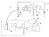
- FIG. 4schematically represents an exemplary CFL ballast 40 and lamp 42 system employing control circuit 20 (FIG. 2 ).
- block 44represents a ballast and lamp system such as of a type described in U.S. Pat. No. 5,965,985, cited hereinabove.
- a convertercomprises switches 120 and 122 that cooperate to provide ac current from a common node 124 to a resonant inductor 126 .
- a resonant load circuit 125includes resonant inductor 126 and resonant capacitor(s) 128 for setting the frequency of resonant operation.
- the gates of switches 120 and 122are connected at a control node 134 .
- Gate drive circuitry 136is connected between the control node and the common node for implementing regenerative control of switches 120 and 122 .
- a gate drive inductor 127is mutually coupled to resonant inductor 126 in order to induce in inductor 127 a voltage proportional to the instantaneous rate of change of current in load circuit 125 .
- a control inductance, comprising coupled windings 30 and 31has inductance L controlled by control circuit 20 (FIG. 2 ).
- winding 30is connected in series with gate drive inductor 127 between the control node and the common node.
- a bidirectional voltage clamp 140connected between nodes 124 and 134 , such as the illustrated back-to-back Zener diodes, cooperates with inductor 30 in such manner that the phase angle between the fundamental frequency component of voltage across resonant load circuit 125 and the ac current in resonant inductor 126 approaches zero during lamp ignition.
- a capacitor 146may be connected in series with inductors 30 and 126 , as shown.
- the lamp currentis regulated by sensing the lamp current using current sensing circuitry 147 and comparing to a reference signal 150 via error amplifier circuitry 149 .
- the output of the error amplifieris used to control the ballast in the manner described herein.
- the reference signal 150 to the error amplifier 149is provided, for example, via a dc power supply 152 and resistors 152 and 154 and may be adjusted in order to adjust the lamp current, which in turn adjusts the lumen output.
- FIG. 5graphically illustrates start-up and steady-state waveforms for the ballast of FIG. 4 :
- Waveform 50represents the duty cycle D;
- waveform 52represents the input to the control circuit at point 53 in the circuit of FIG. 4;
- waveform 54represents the lamp power; and
- waveform 56represents the lamp current.
- the control loopregulates the lamp current. Without the control loop, the ballast would be unstable, and the lamp arc would extinguish.
- FIG. 6graphically illustrates operation of the ballast of FIG. 4 when the in control loop begins to regulate the current.
- Waveform 60represents the PWM signal to switch 22 .
- Waveform 62represents the duty cycle D.
- Waveform 64represents the control inductor (winding 30 ) voltage, and waveform 66 represents the control inductor (winding 30 ) current.
- the pulsed current in the control inductoroccurs when switch 22 is on. While the peak current is high, the average current is such that the equivalent average resistance is the same as the resistance produced by the original circuit of FIG. 1 .
- the duty cyclechanges as the control loop brings the lamp current into regulation.
Landscapes
- Discharge-Lamp Control Circuits And Pulse- Feed Circuits (AREA)
- Circuit Arrangements For Discharge Lamps (AREA)
Abstract
Description
The U.S. Government may have certain rights in this invention pursuant to contract number DEFC2699FT40630 awarded by the U.S. Department of Energy.
Self-oscillating resonant power converters, such as commonly used in compact fluorescent lamp ballasts, for example, typically operate by deriving a transistor switching waveform from one or more windings magnetically coupled to a resonant inductor. U.S. Pat. No. 5,965,985 of Nerone describes a circuit for such a ballast that allows control of the output to a load in order to provide lamp dimming capability. U.S. Pat. No. 5,965,985 describes the control of a self-oscillating ballast by effectively clamping the voltage excursion across an inductor. The effect is to control the reactance of the inductor clamp combination. A similar method of achieving such a result is to vary the effective reactance of a reactive element using a variable resistance coupled in series or parallel therewith. The variable resistance is typically implemented with an active element, e.g., a transistor, wherein the effective resistance across two terminals is a continuous function of the magnitude of the control signal. The applied control signal is also continuous and has a maximum frequency component that is substantially less than the switching frequency of the converter.
It is desirable to implement control circuitry, such as of a type described hereinabove, on an application specific integrated circuit (ASIC) in order to achieve low complexity and cost. It is furthermore desirable to implement as much of the control circuitry as possible in digital form. Unfortunately, the control method described hereinabove inherently requires an analog, continuous signal. Hence, a digital approach, when combined with the control method described hereinabove, requires a digital-to-analog converter to generate the control signal, adding to the complexity of the system. In addition, the analog approach may result in significant power dissipation in the control element, making it impractical to integrate on an ASIC chip. These latter drawbacks may be overcome using a switch control waveform synchronized to the converter power switching waveforms, as known in the art, but for a self-oscillating converter, this results in the requirement of a frequency tracking circuit, such as a zero-crossing detector or phase-locked loop. This requirement may substantially increase cost, complexity, and size of the system.
Accordingly, it is desirable to provide a control for a self-oscillating switching power converter using an active control device in a manner that does not require the control switch waveform to be synchronized with the converter switching frequency. It is furthermore desirable that such control device be operated in a digital manner, that is, with two operating states (on and of f and that the control input for the device also be digital. It is furthermore desirable that such a control avoid compromising the response speed of the converter, so that maximum performance may be obtained.
In accordance with exemplary embodiments of the present invention, a self-oscillating switching power converter has a controllable reactance comprising an active device connected in series or parallel with a reactive element, wherein the effective reactance of the controllable reactance and the active device is controlled such that the control waveform for the active device is binary digital and is not synchronized with the switching converter output frequency. Preferably, the active device is turned completely on and off at a frequency that is substantially greater than the maximum frequency imposed on the output terminals of the active device. The effect of such control is to vary the average resistance across the active device output terminals, and thus the effective output reactance, thereby providing converter output control, while maintaining the response speed of the converter.
FIG. 1 schematically illustrates a control for a switching power converter of a type described by U.S. Pat. No. 5,965,985;
FIG. 2 schematically illustrates a control for a switching power converter in accordance with an exemplary embodiment of the present invention;
FIG. 3 schematically illustrates circuitry and graphs useful for describing operation of the circuit of FIG. 2;
FIG. 4 schematically illustrates an exemplary application for a power converter and control of the present invention in a compact fluorescent lamp ballast;
FIG. 5 graphically illustrates exemplary start-up and steady-state waveforms for the ballast of FIG. 4; and
FIG. 6 graphically illustrates an exemplary transition from start-up to steady-state operation for the ballast of FIG.4.
FIG. 1 illustrates a known implementation of a variablereactance control circuit 10 for a self-oscillating power converter. The control circuit comprises adc control voltage 12 coupled to anactive device 14. Adiode bridge network 16 enables the typically unipolaractive device 14 to function as a bipolar resistive element. In the circuit of FIG. 1, the controlled reactive element comprises aninductor 18. The effective resistance across terminals A and B of FIG. 1 is a continuous function of the magnitude of the control signal applied todevice 14. The applied control signal is also continuous and has a maximum frequency component substantially less than the switching frequency of the converter. The variation in resistance across terminals A and B results in a varied effective inductance, the switching converter output being controlled thereby.
Disadvantageously, the circuit of FIG. 1 is not practicable for ASIC applications, such as, for example, a compact fluorescent lamp ballast, due to the complexity of adding a required digital-to-analog converter and also the difficulty of integrating a control device capable of dissipating sufficient power for such application on an ASIC chip. Moreover, the circuit of FIG. 1 is not capable of an all-digital ASIC implementation.
FIG. 2 illustrates a variablereactance control circuit 20 useful in a self-oscillating switching converter in accordance with exemplary embodiments of the present invention.Control circuit 20 comprises a bi-directionalactive device 21 having apulse modulator 24 with acontrol input 23 thereto. Adiode network 26 enables bi-directional operation to be achieved with a typically uni-directionalactive device 22. A resistor28 (R) is coupled betweenswitch 22 and thediode network 26. Thereactance 30 to be controlled is illustrated in FIG. 2 as comprising aninductor 31.
In operation, the control frequency FCfordevice 22 is substantially greater than the maximum switching frequency FSimposed on terminals A and B. Typical values of FSmight lie in the range of 10 kHz to 200 kHz, and a typical value for FCcould be 1 MHz. In one embodiment,pulse modulator 24 provides a pulse width modulated (PWM) waveform with a duty cycle D. FIG. 3 illustrates PWM control and the effective resistance between terminals A and B, as represented by Vtest/Itest. The effect of the PWM waveform is to vary the average resistance in parallel with the inductance L between terminals A and B, wherein the average equivalent resistance32 (Req) is given by Req =R/D, assuming that the value of resistance R is substantially greater than the on-resistance ofswitch 22. As a result, the effective resistance between terminals A and B is varied to provide the desirable control.
Advantageously, because the control frequency ofswitch 22 is substantially greater than the converter output frequency, the intrinsic bandwidth of the converter is not compromised. In particular, the control switch can respond to a change in input several times during each switching cycle, whereas the response of the switching converter is limited by the switching frequency and the even slower response of the reactive elements that form part of most switching converters. Thus, the control device is faster than the switching converter; hence, the bandwidth of the total system is limited by the switching converter. In addition, because no synchronization is required, circuit complexity is reduced. Another advantage is that more of the control ASIC is implementable in digital form, while reducing the analog portion. As a result, the converter is more robust, costs less, and has fewer ASIC support components. Still further, since the value R is substantially greater than the on-resistance ofswitch 22, most of the power dissipation occurs in R. The component R is preferably not on the ASIC, and the reduced dissipation inswitch 22 enables integration ofswitch 22 on the ASIC. As yet another advantage, the effective resistance is substantially independent of active device parameters such that the effect is more consistent and predictable even with relatively large active device parameter variations.
An exemplary application for a variable reactance control in accordance with preferred embodiments of the present invention is in a dimmable compact fluorescent lamp (CFL) ballast. FIG. 4 schematically represents anexemplary CFL ballast 40 andlamp 42 system employing control circuit20 (FIG.2). in FIG. 4, block44 represents a ballast and lamp system such as of a type described in U.S. Pat. No. 5,965,985, cited hereinabove. In the ballast, a converter comprisesswitches common node 124 to aresonant inductor 126. Aresonant load circuit 125 includesresonant inductor 126 and resonant capacitor(s)128 for setting the frequency of resonant operation. The gates ofswitches control node 134.Gate drive circuitry 136 is connected between the control node and the common node for implementing regenerative control ofswitches resonant inductor 126 in order to induce in inductor127 a voltage proportional to the instantaneous rate of change of current inload circuit 125. A control inductance, comprising coupledwindings bidirectional voltage clamp 140 connected betweennodes inductor 30 in such manner that the phase angle between the fundamental frequency component of voltage acrossresonant load circuit 125 and the ac current inresonant inductor 126 approaches zero during lamp ignition. Acapacitor 146 may be connected in series withinductors current sensing circuitry 147 and comparing to areference signal 150 viaerror amplifier circuitry 149. The output of the error amplifier is used to control the ballast in the manner described herein. In the exemplary dimmable ballast application, thereference signal 150 to theerror amplifier 149 is provided, for example, via adc power supply 152 andresistors
FIG. 5 graphically illustrates start-up and steady-state waveforms for the ballast of FIG.4:Waveform 50 represents the duty cycle D;waveform 52 represents the input to the control circuit atpoint 53 in the circuit of FIG. 4;waveform 54 represents the lamp power; andwaveform 56 represents the lamp current. As illustrated, after an initial transient55, the control loop regulates the lamp current. Without the control loop, the ballast would be unstable, and the lamp arc would extinguish.
FIG. 6 graphically illustrates operation of the ballast of FIG. 4 when the in control loop begins to regulate the current. Waveform60 represents the PWM signal to switch22.Waveform 62 represents the dutycycle D. Waveform 64 represents the control inductor (winding30) voltage, andwaveform 66 represents the control inductor (winding30) current. The pulsed current in the control inductor occurs whenswitch 22 is on. While the peak current is high, the average current is such that the equivalent average resistance is the same as the resistance produced by the original circuit of FIG.1. The duty cycle changes as the control loop brings the lamp current into regulation.
While the preferred embodiments of the present invention have been shown and described herein, it will be obvious that such embodiments are provided by way of example only. Numerous variations, changes and substitutions will occur to those of skill in the art without departing from the invention herein. Accordingly, it is intended that the invention be limited only by the spirit and scope of the appended claims.
Claims (8)
1. A control circuit for a self-oscillating switching power converter, comprising:
a pulse modulator for receiving control signals from a control input and providing pulse modulated control signals therefrom;
a bi-directional active control device for receiving the modulated control signals from the pulse modulator;
a controlled reactance coupled to the active control device;
the pulse modulator turning on and off the active control device at a frequency greater than the maximum switching frequency of the converter in order to vary the effective resistance of the combination of the controlled reactance and the active control device such that the effective reactance thereof is controlled in accordance therewith.
2. The control circuit ofclaim 1 wherein the controlled reactance comprises a controlled inductor having at least one winding.
3. The control ofclaim 1 wherein the bi-directional active control device comprises a switching device coupled to a diode network.
4. The control ofclaim 1 wherein the pulse modulator comprises a pulse width modulator.
5. A dimmable self-oscillating ballast for a fluorescent lamp, comprising:
a resonant load circuit for coupling to the lamp, the resonant load circuit comprising a resonant inductor and a resonant capacitor;
a converter coupled to the resonant load circuit for inducing ac current therein, the converter comprising a pair of switching devices and connected at a common node;
gate drive circuitry for controlling the switching devices, the gate drive circuitry comprising a gate drive inductor coupled between the common node and a control node;
a converter control circuit comprising a pulse modulator for receiving control signals from a control input and providing pulse modulated control signals therefrom;
a bi-directional active control device for receiving the modulated control signals from the pulse modulator; and
a controlled reactance coupled to the active control device;
the pulse modulator turning on and off the active control device at a frequency greater than the maximum output frequency of the converter in order to vary the effective resistance of the combination of the controlled reactance and the active control device such that the effective reactance at the output of the converter is controlled in accordance therewith.
6. The ballast ofclaim 5 wherein the controlled reactance comprises a controlled inductor having at least one winding.
7. The ballast ofclaim 5 wherein the bi-directional active control device21 comprises a switching device coupled to a diode network.
8. The ballast ofclaim 5 wherein the pulse modulator comprises a pulse width modulator.
Priority Applications (1)
| Application Number | Priority Date | Filing Date | Title |
|---|---|---|---|
| US09/681,395US6407514B1 (en) | 2001-03-29 | 2001-03-29 | Non-synchronous control of self-oscillating resonant converters |
Applications Claiming Priority (1)
| Application Number | Priority Date | Filing Date | Title |
|---|---|---|---|
| US09/681,395US6407514B1 (en) | 2001-03-29 | 2001-03-29 | Non-synchronous control of self-oscillating resonant converters |
Publications (1)
| Publication Number | Publication Date |
|---|---|
| US6407514B1true US6407514B1 (en) | 2002-06-18 |
Family
ID=24735100
Family Applications (1)
| Application Number | Title | Priority Date | Filing Date |
|---|---|---|---|
| US09/681,395Expired - Fee RelatedUS6407514B1 (en) | 2001-03-29 | 2001-03-29 | Non-synchronous control of self-oscillating resonant converters |
Country Status (1)
| Country | Link |
|---|---|
| US (1) | US6407514B1 (en) |
Cited By (81)
| Publication number | Priority date | Publication date | Assignee | Title |
|---|---|---|---|---|
| US20050134119A1 (en)* | 2003-12-18 | 2005-06-23 | Bliley Paul D. | Time slotting power switching |
| US7000128B1 (en) | 2002-12-30 | 2006-02-14 | National Semiconductor Corporation | Method and apparatus for reducing capacitive load-related power loss by gate charge adjustment |
| US20070263415A1 (en)* | 2006-02-14 | 2007-11-15 | Arian Jansen | Two terminals quasi resonant tank circuit |
| US20080074095A1 (en)* | 2006-09-25 | 2008-03-27 | Telefus Mark D | Bi-directional regulator |
| US20080238379A1 (en)* | 2007-03-29 | 2008-10-02 | Mark Telefus | Pulse frequency to voltage conversion |
| US20080238600A1 (en)* | 2007-03-29 | 2008-10-02 | Olson Bruce D | Method of producing a multi-turn coil from folded flexible circuitry |
| US20080239760A1 (en)* | 2007-03-29 | 2008-10-02 | Mark Telefus | Primary only constant voltage/constant current (CVCC) control in quasi resonant convertor |
| US20080238389A1 (en)* | 2007-03-29 | 2008-10-02 | Mark Telefus | Primary only control quasi resonant convertor |
| US20090290384A1 (en)* | 2008-05-21 | 2009-11-26 | Flextronics, Ap, Llc | High power factor isolated buck-type power factor correction converter |
| US20090289565A1 (en)* | 2008-05-23 | 2009-11-26 | Osram Sylvania Inc. | Aggregate ignition method in high frequency metal halide lamps |
| US20090290385A1 (en)* | 2008-05-21 | 2009-11-26 | Flextronics Ap, Llc | Resonant power factor correction converter |
| US20090289572A1 (en)* | 2008-05-23 | 2009-11-26 | Osram Sylvania Inc. | Ignition for ceramic metal halide high frequency ballasts |
| US20090289564A1 (en)* | 2008-05-23 | 2009-11-26 | Osram Sylvania Inc. | Ceramic metal halide lamp bi-modal power regulation control |
| US20090289573A1 (en)* | 2008-05-23 | 2009-11-26 | Osram Sylvania Inc. | Microcontroller based ignition in high frequency ceramic metal halide lamps |
| US20090295531A1 (en)* | 2008-05-28 | 2009-12-03 | Arturo Silva | Optimized litz wire |
| WO2010011971A1 (en)* | 2008-07-25 | 2010-01-28 | Cirrus Logic, Inc. | Switching power converter control with triac-based leading edge dimmer compatibility |
| US20100060202A1 (en)* | 2007-03-12 | 2010-03-11 | Melanson John L | Lighting System with Lighting Dimmer Output Mapping |
| US20100079125A1 (en)* | 2008-07-25 | 2010-04-01 | Melanson John L | Current sensing in a switching power converter |
| US20100117554A1 (en)* | 2008-05-23 | 2010-05-13 | Osram Sylvania Inc. | High Frequency Integrated HID Lamp With Run-Up Current |
| US20100127737A1 (en)* | 2008-11-21 | 2010-05-27 | Flextronics Ap, Llc | Variable PFC and grid-tied bus voltage control |
| US20100171442A1 (en)* | 2008-12-12 | 2010-07-08 | Draper William A | Light Emitting Diode Based Lighting System With Time Division Ambient Light Feedback Response |
| US20100244726A1 (en)* | 2008-12-07 | 2010-09-30 | Melanson John L | Primary-side based control of secondary-side current for a transformer |
| US20100253305A1 (en)* | 2007-03-12 | 2010-10-07 | Melanson John L | Switching power converter control with spread spectrum based electromagnetic interference reduction |
| US20100289466A1 (en)* | 2009-05-15 | 2010-11-18 | Flextronics Ap, Llc | Closed loop negative feedback system with low frequency modulated gain |
| US20100308742A1 (en)* | 2007-03-12 | 2010-12-09 | Melanson John L | Power Control System for Current Regulated Light Sources |
| US20100327765A1 (en)* | 2009-06-30 | 2010-12-30 | Melanson John L | Low energy transfer mode for auxiliary power supply operation in a cascaded switching power converter |
| US20110110000A1 (en)* | 2009-11-09 | 2011-05-12 | Etter Brett E | Power System Having Voltage-Based Monitoring for Over Current Protection |
| US7978489B1 (en) | 2007-08-03 | 2011-07-12 | Flextronics Ap, Llc | Integrated power converters |
| US20110170325A1 (en)* | 2010-01-14 | 2011-07-14 | Flextronics Ap, Llc | Line switcher for power converters |
| US20110203840A1 (en)* | 2010-02-23 | 2011-08-25 | Flextronics Ap, Llc | Test point design for a high speed bus |
| US8040703B2 (en) | 2007-05-02 | 2011-10-18 | Cirrus Logic, Inc. | Power factor correction controller with feedback reduction |
| US8076920B1 (en) | 2007-03-12 | 2011-12-13 | Cirrus Logic, Inc. | Switching power converter and control system |
| US8198874B2 (en) | 2009-06-30 | 2012-06-12 | Cirrus Logic, Inc. | Switching power converter with current sensing transformer auxiliary power supply |
| US8222872B1 (en) | 2008-09-30 | 2012-07-17 | Cirrus Logic, Inc. | Switching power converter with selectable mode auxiliary power supply |
| US8248145B2 (en) | 2009-06-30 | 2012-08-21 | Cirrus Logic, Inc. | Cascode configured switching using at least one low breakdown voltage internal, integrated circuit switch to control at least one high breakdown voltage external switch |
| US8279628B2 (en) | 2008-07-25 | 2012-10-02 | Cirrus Logic, Inc. | Audible noise suppression in a resonant switching power converter |
| US8279646B1 (en) | 2007-12-14 | 2012-10-02 | Flextronics Ap, Llc | Coordinated power sequencing to limit inrush currents and ensure optimum filtering |
| US8299722B2 (en) | 2008-12-12 | 2012-10-30 | Cirrus Logic, Inc. | Time division light output sensing and brightness adjustment for different spectra of light emitting diodes |
| US20130049629A1 (en)* | 2011-08-23 | 2013-02-28 | Delta Electronics (Shanghai) Co., Ltd. | Electronic ballast |
| US8482223B2 (en) | 2009-04-30 | 2013-07-09 | Cirrus Logic, Inc. | Calibration of lamps |
| US8488340B2 (en) | 2010-08-27 | 2013-07-16 | Flextronics Ap, Llc | Power converter with boost-buck-buck configuration utilizing an intermediate power regulating circuit |
| US8536799B1 (en) | 2010-07-30 | 2013-09-17 | Cirrus Logic, Inc. | Dimmer detection |
| US8569972B2 (en) | 2010-08-17 | 2013-10-29 | Cirrus Logic, Inc. | Dimmer output emulation |
| US8576589B2 (en) | 2008-01-30 | 2013-11-05 | Cirrus Logic, Inc. | Switch state controller with a sense current generated operating voltage |
| US8941316B2 (en) | 2010-08-17 | 2015-01-27 | Cirrus Logic, Inc. | Duty factor probing of a triac-based dimmer |
| US8947016B2 (en) | 2010-07-30 | 2015-02-03 | Cirrus Logic, Inc. | Transformer-isolated LED lighting circuit with secondary-side dimming control |
| US8963535B1 (en) | 2009-06-30 | 2015-02-24 | Cirrus Logic, Inc. | Switch controlled current sensing using a hall effect sensor |
| US8964413B2 (en) | 2010-04-22 | 2015-02-24 | Flextronics Ap, Llc | Two stage resonant converter enabling soft-switching in an isolated stage |
| US8981661B2 (en) | 2010-07-30 | 2015-03-17 | Cirrus Logic, Inc. | Powering high-efficiency lighting devices from a triac-based dimmer |
| US9025347B2 (en) | 2010-12-16 | 2015-05-05 | Cirrus Logic, Inc. | Switching parameter based discontinuous mode-critical conduction mode transition |
| US9071144B2 (en) | 2011-12-14 | 2015-06-30 | Cirrus Logic, Inc. | Adaptive current control timing and responsive current control for interfacing with a dimmer |
| US9084316B2 (en) | 2010-11-04 | 2015-07-14 | Cirrus Logic, Inc. | Controlled power dissipation in a switch path in a lighting system |
| US9101010B2 (en) | 2013-03-15 | 2015-08-04 | Cirrus Logic, Inc. | High-efficiency lighting devices having dimmer and/or load condition measurement |
| US9117991B1 (en) | 2012-02-10 | 2015-08-25 | Flextronics Ap, Llc | Use of flexible circuits incorporating a heat spreading layer and the rigidizing specific areas within such a construction by creating stiffening structures within said circuits by either folding, bending, forming or combinations thereof |
| US9155174B2 (en) | 2009-09-30 | 2015-10-06 | Cirrus Logic, Inc. | Phase control dimming compatible lighting systems |
| US9155163B2 (en) | 2010-11-16 | 2015-10-06 | Cirrus Logic, Inc. | Trailing edge dimmer compatibility with dimmer high resistance prediction |
| US9167662B2 (en) | 2012-02-29 | 2015-10-20 | Cirrus Logic, Inc. | Mixed load current compensation for LED lighting |
| US9178415B1 (en) | 2009-10-15 | 2015-11-03 | Cirrus Logic, Inc. | Inductor over-current protection using a volt-second value representing an input voltage to a switching power converter |
| US9184661B2 (en) | 2012-08-27 | 2015-11-10 | Cirrus Logic, Inc. | Power conversion with controlled capacitance charging including attach state control |
| US9215772B2 (en) | 2014-04-17 | 2015-12-15 | Philips International B.V. | Systems and methods for minimizing power dissipation in a low-power lamp coupled to a trailing-edge dimmer |
| US9240725B2 (en) | 2010-07-30 | 2016-01-19 | Cirrus Logic, Inc. | Coordinated dimmer compatibility functions |
| US9307601B2 (en) | 2010-08-17 | 2016-04-05 | Koninklijke Philips N.V. | Input voltage sensing for a switching power converter and a triac-based dimmer |
| US9491845B2 (en) | 2010-11-04 | 2016-11-08 | Koninklijke Philips N.V. | Controlled power dissipation in a link path in a lighting system |
| US9496844B1 (en) | 2013-01-25 | 2016-11-15 | Koninklijke Philips N.V. | Variable bandwidth filter for dimmer phase angle measurements |
| US9524861B2 (en) | 2012-11-26 | 2016-12-20 | Lucidity Lights, Inc. | Fast start RF induction lamp |
| US9532415B2 (en) | 2010-08-24 | 2016-12-27 | Philips Lighting Hiolding B.V. | Multi-mode dimmer interfacing including attach state control |
| US9549463B1 (en) | 2014-05-16 | 2017-01-17 | Multek Technologies, Ltd. | Rigid to flexible PC transition |
| US9621062B2 (en) | 2014-03-07 | 2017-04-11 | Philips Lighting Holding B.V. | Dimmer output emulation with non-zero glue voltage |
| US9661743B1 (en) | 2013-12-09 | 2017-05-23 | Multek Technologies, Ltd. | Flexible circuit board and method of fabricating |
| US9723713B1 (en) | 2014-05-16 | 2017-08-01 | Multek Technologies, Ltd. | Flexible printed circuit board hinge |
| US9862561B2 (en) | 2012-12-03 | 2018-01-09 | Flextronics Ap, Llc | Driving board folding machine and method of using a driving board folding machine to fold a flexible circuit |
| US9911589B2 (en) | 2012-11-26 | 2018-03-06 | Lucidity Lights, Inc. | Induction RF fluorescent lamp with processor-based external dimmer load control |
| US10128101B2 (en) | 2012-11-26 | 2018-11-13 | Lucidity Lights, Inc. | Dimmable induction RF fluorescent lamp with reduced electromagnetic interference |
| US10141179B2 (en) | 2012-11-26 | 2018-11-27 | Lucidity Lights, Inc. | Fast start RF induction lamp with metallic structure |
| US10154583B1 (en) | 2015-03-27 | 2018-12-11 | Flex Ltd | Mechanical strain reduction on flexible and rigid-flexible circuits |
| US10187934B2 (en) | 2013-03-14 | 2019-01-22 | Philips Lighting Holding B.V. | Controlled electronic system power dissipation via an auxiliary-power dissipation circuit |
| US10236174B1 (en) | 2017-12-28 | 2019-03-19 | Lucidity Lights, Inc. | Lumen maintenance in fluorescent lamps |
| USD854198S1 (en) | 2017-12-28 | 2019-07-16 | Lucidity Lights, Inc. | Inductive lamp |
| US10356857B2 (en) | 2007-03-12 | 2019-07-16 | Signify Holding B.V. | Lighting system with power factor correction control data determined from a phase modulated signal |
| US10529551B2 (en) | 2012-11-26 | 2020-01-07 | Lucidity Lights, Inc. | Fast start fluorescent light bulb |
| US11382192B2 (en) | 2019-02-08 | 2022-07-05 | Lucidity Lights, Inc. | Preferred lighting spectrum and color shifting circadian lamps |
Citations (4)
| Publication number | Priority date | Publication date | Assignee | Title |
|---|---|---|---|---|
| US4464606A (en)* | 1981-03-25 | 1984-08-07 | Armstrong World Industries, Inc. | Pulse width modulated dimming arrangement for fluorescent lamps |
| US4667132A (en)* | 1986-03-03 | 1987-05-19 | Dianalog Systems, Inc. | Electronic transformer system for neon lamps |
| US5945783A (en) | 1998-07-13 | 1999-08-31 | General Electric Company | Zero energy-storage ballast for compact fluorescent lamps |
| US5965985A (en) | 1996-09-06 | 1999-10-12 | General Electric Company | Dimmable ballast with complementary converter switches |
- 2001
- 2001-03-29USUS09/681,395patent/US6407514B1/ennot_activeExpired - Fee Related
Patent Citations (4)
| Publication number | Priority date | Publication date | Assignee | Title |
|---|---|---|---|---|
| US4464606A (en)* | 1981-03-25 | 1984-08-07 | Armstrong World Industries, Inc. | Pulse width modulated dimming arrangement for fluorescent lamps |
| US4667132A (en)* | 1986-03-03 | 1987-05-19 | Dianalog Systems, Inc. | Electronic transformer system for neon lamps |
| US5965985A (en) | 1996-09-06 | 1999-10-12 | General Electric Company | Dimmable ballast with complementary converter switches |
| US5945783A (en) | 1998-07-13 | 1999-08-31 | General Electric Company | Zero energy-storage ballast for compact fluorescent lamps |
Non-Patent Citations (1)
| Title |
|---|
| "Electrodeless Fluorescent Lamp Dimming System," L. Nerone, Serial No. 09/318,343 (GE docket LD 11157), filed May 25, 1999, allowed Aug. 29, 2000. |
Cited By (129)
| Publication number | Priority date | Publication date | Assignee | Title |
|---|---|---|---|---|
| US7000128B1 (en) | 2002-12-30 | 2006-02-14 | National Semiconductor Corporation | Method and apparatus for reducing capacitive load-related power loss by gate charge adjustment |
| US20050134119A1 (en)* | 2003-12-18 | 2005-06-23 | Bliley Paul D. | Time slotting power switching |
| US7764515B2 (en) | 2006-02-14 | 2010-07-27 | Flextronics Ap, Llc | Two terminals quasi resonant tank circuit |
| US7924577B2 (en) | 2006-02-14 | 2011-04-12 | Flextronics Ap, Llc | Two terminals quasi resonant tank circuit |
| WO2007095346A3 (en)* | 2006-02-14 | 2008-08-07 | Flextronics Ap Llc | Two terminals quasi resonant tank circuit |
| US20100067276A1 (en)* | 2006-02-14 | 2010-03-18 | Flextronics Ap, Llc | Two terminals quasi resonant tank circuit |
| US20100061123A1 (en)* | 2006-02-14 | 2010-03-11 | Flextronics Ap, Llc | Two terminals quasi resonant tank circuit |
| US20070263415A1 (en)* | 2006-02-14 | 2007-11-15 | Arian Jansen | Two terminals quasi resonant tank circuit |
| US7924578B2 (en) | 2006-02-14 | 2011-04-12 | Flextronics Ap, Llc | Two terminals quasi resonant tank circuit |
| US20080074095A1 (en)* | 2006-09-25 | 2008-03-27 | Telefus Mark D | Bi-directional regulator |
| US8223522B2 (en) | 2006-09-25 | 2012-07-17 | Flextronics Ap, Llc | Bi-directional regulator for regulating power |
| US8076920B1 (en) | 2007-03-12 | 2011-12-13 | Cirrus Logic, Inc. | Switching power converter and control system |
| US8536794B2 (en) | 2007-03-12 | 2013-09-17 | Cirrus Logic, Inc. | Lighting system with lighting dimmer output mapping |
| US20100308742A1 (en)* | 2007-03-12 | 2010-12-09 | Melanson John L | Power Control System for Current Regulated Light Sources |
| US20100253305A1 (en)* | 2007-03-12 | 2010-10-07 | Melanson John L | Switching power converter control with spread spectrum based electromagnetic interference reduction |
| US8723438B2 (en) | 2007-03-12 | 2014-05-13 | Cirrus Logic, Inc. | Switch power converter control with spread spectrum based electromagnetic interference reduction |
| US10356857B2 (en) | 2007-03-12 | 2019-07-16 | Signify Holding B.V. | Lighting system with power factor correction control data determined from a phase modulated signal |
| US20100060202A1 (en)* | 2007-03-12 | 2010-03-11 | Melanson John L | Lighting System with Lighting Dimmer Output Mapping |
| US8232736B2 (en) | 2007-03-12 | 2012-07-31 | Cirrus Logic, Inc. | Power control system for current regulated light sources |
| US8174204B2 (en) | 2007-03-12 | 2012-05-08 | Cirrus Logic, Inc. | Lighting system with power factor correction control data determined from a phase modulated signal |
| US9000680B2 (en) | 2007-03-12 | 2015-04-07 | Cirrus Logic, Inc. | Lighting system with lighting dimmer output mapping |
| US8387234B2 (en) | 2007-03-29 | 2013-03-05 | Flextronics Ap, Llc | Multi-turn coil device |
| US20110050381A1 (en)* | 2007-03-29 | 2011-03-03 | Flextronics Ap, Llc | Method of producing a multi-turn coil from folded flexible circuitry |
| US8191241B2 (en) | 2007-03-29 | 2012-06-05 | Flextronics Ap, Llc | Method of producing a multi-turn coil from folded flexible circuitry |
| US7755914B2 (en) | 2007-03-29 | 2010-07-13 | Flextronics Ap, Llc | Pulse frequency to voltage conversion |
| US7760519B2 (en) | 2007-03-29 | 2010-07-20 | Flextronics Ap, Llc | Primary only control quasi resonant convertor |
| US20080238379A1 (en)* | 2007-03-29 | 2008-10-02 | Mark Telefus | Pulse frequency to voltage conversion |
| US20080238600A1 (en)* | 2007-03-29 | 2008-10-02 | Olson Bruce D | Method of producing a multi-turn coil from folded flexible circuitry |
| US20080239760A1 (en)* | 2007-03-29 | 2008-10-02 | Mark Telefus | Primary only constant voltage/constant current (CVCC) control in quasi resonant convertor |
| US7830676B2 (en) | 2007-03-29 | 2010-11-09 | Flextronics Ap, Llc | Primary only constant voltage/constant current (CVCC) control in quasi resonant convertor |
| US20080238389A1 (en)* | 2007-03-29 | 2008-10-02 | Mark Telefus | Primary only control quasi resonant convertor |
| US8040703B2 (en) | 2007-05-02 | 2011-10-18 | Cirrus Logic, Inc. | Power factor correction controller with feedback reduction |
| US8120341B2 (en) | 2007-05-02 | 2012-02-21 | Cirrus Logic, Inc. | Switching power converter with switch control pulse width variability at low power demand levels |
| US7978489B1 (en) | 2007-08-03 | 2011-07-12 | Flextronics Ap, Llc | Integrated power converters |
| US8279646B1 (en) | 2007-12-14 | 2012-10-02 | Flextronics Ap, Llc | Coordinated power sequencing to limit inrush currents and ensure optimum filtering |
| US8576589B2 (en) | 2008-01-30 | 2013-11-05 | Cirrus Logic, Inc. | Switch state controller with a sense current generated operating voltage |
| US20090290385A1 (en)* | 2008-05-21 | 2009-11-26 | Flextronics Ap, Llc | Resonant power factor correction converter |
| US8693213B2 (en) | 2008-05-21 | 2014-04-08 | Flextronics Ap, Llc | Resonant power factor correction converter |
| US8102678B2 (en) | 2008-05-21 | 2012-01-24 | Flextronics Ap, Llc | High power factor isolated buck-type power factor correction converter |
| US20090290384A1 (en)* | 2008-05-21 | 2009-11-26 | Flextronics, Ap, Llc | High power factor isolated buck-type power factor correction converter |
| US20090289573A1 (en)* | 2008-05-23 | 2009-11-26 | Osram Sylvania Inc. | Microcontroller based ignition in high frequency ceramic metal halide lamps |
| US8378585B2 (en) | 2008-05-23 | 2013-02-19 | Osram Sylvania Inc. | High frequency integrated HID lamp with run-up current |
| US7839098B2 (en) | 2008-05-23 | 2010-11-23 | Osram Sylvania Inc. | Microcontroller based ignition in high frequency ceramic metal halide lamps |
| US7863827B2 (en) | 2008-05-23 | 2011-01-04 | Osram Sylvania Inc. | Ceramic metal halide lamp bi-modal power regulation control |
| US8076865B2 (en) | 2008-05-23 | 2011-12-13 | Osram Sylvania Inc. | Ignition for ceramic metal halide high frequency ballasts |
| US20090289564A1 (en)* | 2008-05-23 | 2009-11-26 | Osram Sylvania Inc. | Ceramic metal halide lamp bi-modal power regulation control |
| US7919926B2 (en) | 2008-05-23 | 2011-04-05 | Osram Sylvania Inc. | Aggregate ignition method in high frequency metal halide lamps |
| US20090289565A1 (en)* | 2008-05-23 | 2009-11-26 | Osram Sylvania Inc. | Aggregate ignition method in high frequency metal halide lamps |
| US20090289572A1 (en)* | 2008-05-23 | 2009-11-26 | Osram Sylvania Inc. | Ignition for ceramic metal halide high frequency ballasts |
| US20100117554A1 (en)* | 2008-05-23 | 2010-05-13 | Osram Sylvania Inc. | High Frequency Integrated HID Lamp With Run-Up Current |
| US8975523B2 (en) | 2008-05-28 | 2015-03-10 | Flextronics Ap, Llc | Optimized litz wire |
| US20090295531A1 (en)* | 2008-05-28 | 2009-12-03 | Arturo Silva | Optimized litz wire |
| US8344707B2 (en) | 2008-07-25 | 2013-01-01 | Cirrus Logic, Inc. | Current sensing in a switching power converter |
| US8553430B2 (en) | 2008-07-25 | 2013-10-08 | Cirrus Logic, Inc. | Resonant switching power converter with adaptive dead time control |
| US8212491B2 (en) | 2008-07-25 | 2012-07-03 | Cirrus Logic, Inc. | Switching power converter control with triac-based leading edge dimmer compatibility |
| TWI496408B (en)* | 2008-07-25 | 2015-08-11 | Cirrus Logic Inc | Controller, electronic system and method for controlling a switched power converter and providing compatibility between the switched power converter and a bidirectional rectifier based dimmer |
| WO2010011971A1 (en)* | 2008-07-25 | 2010-01-28 | Cirrus Logic, Inc. | Switching power converter control with triac-based leading edge dimmer compatibility |
| US20100079125A1 (en)* | 2008-07-25 | 2010-04-01 | Melanson John L | Current sensing in a switching power converter |
| US8279628B2 (en) | 2008-07-25 | 2012-10-02 | Cirrus Logic, Inc. | Audible noise suppression in a resonant switching power converter |
| US8330434B2 (en) | 2008-07-25 | 2012-12-11 | Cirrus Logic, Inc. | Power supply that determines energy consumption and outputs a signal indicative of energy consumption |
| US8222872B1 (en) | 2008-09-30 | 2012-07-17 | Cirrus Logic, Inc. | Switching power converter with selectable mode auxiliary power supply |
| US20100127737A1 (en)* | 2008-11-21 | 2010-05-27 | Flextronics Ap, Llc | Variable PFC and grid-tied bus voltage control |
| US8081019B2 (en) | 2008-11-21 | 2011-12-20 | Flextronics Ap, Llc | Variable PFC and grid-tied bus voltage control |
| US8288954B2 (en) | 2008-12-07 | 2012-10-16 | Cirrus Logic, Inc. | Primary-side based control of secondary-side current for a transformer |
| US20100244726A1 (en)* | 2008-12-07 | 2010-09-30 | Melanson John L | Primary-side based control of secondary-side current for a transformer |
| US8299722B2 (en) | 2008-12-12 | 2012-10-30 | Cirrus Logic, Inc. | Time division light output sensing and brightness adjustment for different spectra of light emitting diodes |
| US20100171442A1 (en)* | 2008-12-12 | 2010-07-08 | Draper William A | Light Emitting Diode Based Lighting System With Time Division Ambient Light Feedback Response |
| US8362707B2 (en) | 2008-12-12 | 2013-01-29 | Cirrus Logic, Inc. | Light emitting diode based lighting system with time division ambient light feedback response |
| US8482223B2 (en) | 2009-04-30 | 2013-07-09 | Cirrus Logic, Inc. | Calibration of lamps |
| US8040117B2 (en) | 2009-05-15 | 2011-10-18 | Flextronics Ap, Llc | Closed loop negative feedback system with low frequency modulated gain |
| US20100289466A1 (en)* | 2009-05-15 | 2010-11-18 | Flextronics Ap, Llc | Closed loop negative feedback system with low frequency modulated gain |
| US20100327765A1 (en)* | 2009-06-30 | 2010-12-30 | Melanson John L | Low energy transfer mode for auxiliary power supply operation in a cascaded switching power converter |
| US8212493B2 (en) | 2009-06-30 | 2012-07-03 | Cirrus Logic, Inc. | Low energy transfer mode for auxiliary power supply operation in a cascaded switching power converter |
| US8198874B2 (en) | 2009-06-30 | 2012-06-12 | Cirrus Logic, Inc. | Switching power converter with current sensing transformer auxiliary power supply |
| US8963535B1 (en) | 2009-06-30 | 2015-02-24 | Cirrus Logic, Inc. | Switch controlled current sensing using a hall effect sensor |
| US8248145B2 (en) | 2009-06-30 | 2012-08-21 | Cirrus Logic, Inc. | Cascode configured switching using at least one low breakdown voltage internal, integrated circuit switch to control at least one high breakdown voltage external switch |
| US9155174B2 (en) | 2009-09-30 | 2015-10-06 | Cirrus Logic, Inc. | Phase control dimming compatible lighting systems |
| US9178415B1 (en) | 2009-10-15 | 2015-11-03 | Cirrus Logic, Inc. | Inductor over-current protection using a volt-second value representing an input voltage to a switching power converter |
| US8654483B2 (en) | 2009-11-09 | 2014-02-18 | Cirrus Logic, Inc. | Power system having voltage-based monitoring for over current protection |
| US20110110000A1 (en)* | 2009-11-09 | 2011-05-12 | Etter Brett E | Power System Having Voltage-Based Monitoring for Over Current Protection |
| US20110170325A1 (en)* | 2010-01-14 | 2011-07-14 | Flextronics Ap, Llc | Line switcher for power converters |
| US8289741B2 (en) | 2010-01-14 | 2012-10-16 | Flextronics Ap, Llc | Line switcher for power converters |
| US20110203840A1 (en)* | 2010-02-23 | 2011-08-25 | Flextronics Ap, Llc | Test point design for a high speed bus |
| US8586873B2 (en) | 2010-02-23 | 2013-11-19 | Flextronics Ap, Llc | Test point design for a high speed bus |
| US8964413B2 (en) | 2010-04-22 | 2015-02-24 | Flextronics Ap, Llc | Two stage resonant converter enabling soft-switching in an isolated stage |
| US8981661B2 (en) | 2010-07-30 | 2015-03-17 | Cirrus Logic, Inc. | Powering high-efficiency lighting devices from a triac-based dimmer |
| US8947016B2 (en) | 2010-07-30 | 2015-02-03 | Cirrus Logic, Inc. | Transformer-isolated LED lighting circuit with secondary-side dimming control |
| US8536799B1 (en) | 2010-07-30 | 2013-09-17 | Cirrus Logic, Inc. | Dimmer detection |
| US9240725B2 (en) | 2010-07-30 | 2016-01-19 | Cirrus Logic, Inc. | Coordinated dimmer compatibility functions |
| US9660547B1 (en) | 2010-07-30 | 2017-05-23 | Philips Lighting Holding B.V. | Dimmer compatibility with reactive loads |
| US8941316B2 (en) | 2010-08-17 | 2015-01-27 | Cirrus Logic, Inc. | Duty factor probing of a triac-based dimmer |
| US9504111B2 (en) | 2010-08-17 | 2016-11-22 | Koninklijke Philips N.V. | Duty factor probing of a triac-based dimmer |
| US9307601B2 (en) | 2010-08-17 | 2016-04-05 | Koninklijke Philips N.V. | Input voltage sensing for a switching power converter and a triac-based dimmer |
| US8569972B2 (en) | 2010-08-17 | 2013-10-29 | Cirrus Logic, Inc. | Dimmer output emulation |
| US9532415B2 (en) | 2010-08-24 | 2016-12-27 | Philips Lighting Hiolding B.V. | Multi-mode dimmer interfacing including attach state control |
| US8488340B2 (en) | 2010-08-27 | 2013-07-16 | Flextronics Ap, Llc | Power converter with boost-buck-buck configuration utilizing an intermediate power regulating circuit |
| US9491845B2 (en) | 2010-11-04 | 2016-11-08 | Koninklijke Philips N.V. | Controlled power dissipation in a link path in a lighting system |
| US9497851B2 (en) | 2010-11-04 | 2016-11-15 | Koninklijke Philips N.V. | Thermal management in a lighting system using multiple, controlled power dissipation circuits |
| US9497850B2 (en) | 2010-11-04 | 2016-11-15 | Koninklijke Philips N.V. | Controlled power dissipation in a lighting system |
| US9084316B2 (en) | 2010-11-04 | 2015-07-14 | Cirrus Logic, Inc. | Controlled power dissipation in a switch path in a lighting system |
| US9207265B1 (en) | 2010-11-12 | 2015-12-08 | Cirrus Logic, Inc. | Dimmer detection |
| US9155163B2 (en) | 2010-11-16 | 2015-10-06 | Cirrus Logic, Inc. | Trailing edge dimmer compatibility with dimmer high resistance prediction |
| US9025347B2 (en) | 2010-12-16 | 2015-05-05 | Cirrus Logic, Inc. | Switching parameter based discontinuous mode-critical conduction mode transition |
| US8884542B2 (en)* | 2011-08-23 | 2014-11-11 | Delta Electronics (Shanghai) Co., Ltd. | Self-oscillating dimmable electronic ballast |
| US20130049629A1 (en)* | 2011-08-23 | 2013-02-28 | Delta Electronics (Shanghai) Co., Ltd. | Electronic ballast |
| US9071144B2 (en) | 2011-12-14 | 2015-06-30 | Cirrus Logic, Inc. | Adaptive current control timing and responsive current control for interfacing with a dimmer |
| US9117991B1 (en) | 2012-02-10 | 2015-08-25 | Flextronics Ap, Llc | Use of flexible circuits incorporating a heat spreading layer and the rigidizing specific areas within such a construction by creating stiffening structures within said circuits by either folding, bending, forming or combinations thereof |
| US9167662B2 (en) | 2012-02-29 | 2015-10-20 | Cirrus Logic, Inc. | Mixed load current compensation for LED lighting |
| US9184661B2 (en) | 2012-08-27 | 2015-11-10 | Cirrus Logic, Inc. | Power conversion with controlled capacitance charging including attach state control |
| US10128101B2 (en) | 2012-11-26 | 2018-11-13 | Lucidity Lights, Inc. | Dimmable induction RF fluorescent lamp with reduced electromagnetic interference |
| US10529551B2 (en) | 2012-11-26 | 2020-01-07 | Lucidity Lights, Inc. | Fast start fluorescent light bulb |
| US9524861B2 (en) | 2012-11-26 | 2016-12-20 | Lucidity Lights, Inc. | Fast start RF induction lamp |
| US10141179B2 (en) | 2012-11-26 | 2018-11-27 | Lucidity Lights, Inc. | Fast start RF induction lamp with metallic structure |
| US9911589B2 (en) | 2012-11-26 | 2018-03-06 | Lucidity Lights, Inc. | Induction RF fluorescent lamp with processor-based external dimmer load control |
| US9862561B2 (en) | 2012-12-03 | 2018-01-09 | Flextronics Ap, Llc | Driving board folding machine and method of using a driving board folding machine to fold a flexible circuit |
| US9496844B1 (en) | 2013-01-25 | 2016-11-15 | Koninklijke Philips N.V. | Variable bandwidth filter for dimmer phase angle measurements |
| US10187934B2 (en) | 2013-03-14 | 2019-01-22 | Philips Lighting Holding B.V. | Controlled electronic system power dissipation via an auxiliary-power dissipation circuit |
| US9282598B2 (en) | 2013-03-15 | 2016-03-08 | Koninklijke Philips N.V. | System and method for learning dimmer characteristics |
| US9101010B2 (en) | 2013-03-15 | 2015-08-04 | Cirrus Logic, Inc. | High-efficiency lighting devices having dimmer and/or load condition measurement |
| US9661743B1 (en) | 2013-12-09 | 2017-05-23 | Multek Technologies, Ltd. | Flexible circuit board and method of fabricating |
| US9621062B2 (en) | 2014-03-07 | 2017-04-11 | Philips Lighting Holding B.V. | Dimmer output emulation with non-zero glue voltage |
| US9215772B2 (en) | 2014-04-17 | 2015-12-15 | Philips International B.V. | Systems and methods for minimizing power dissipation in a low-power lamp coupled to a trailing-edge dimmer |
| US9723713B1 (en) | 2014-05-16 | 2017-08-01 | Multek Technologies, Ltd. | Flexible printed circuit board hinge |
| US9549463B1 (en) | 2014-05-16 | 2017-01-17 | Multek Technologies, Ltd. | Rigid to flexible PC transition |
| US10154583B1 (en) | 2015-03-27 | 2018-12-11 | Flex Ltd | Mechanical strain reduction on flexible and rigid-flexible circuits |
| US10236174B1 (en) | 2017-12-28 | 2019-03-19 | Lucidity Lights, Inc. | Lumen maintenance in fluorescent lamps |
| USD854198S1 (en) | 2017-12-28 | 2019-07-16 | Lucidity Lights, Inc. | Inductive lamp |
| US10418233B2 (en) | 2017-12-28 | 2019-09-17 | Lucidity Lights, Inc. | Burst-mode for low power operation of RF fluorescent lamps |
| US11382192B2 (en) | 2019-02-08 | 2022-07-05 | Lucidity Lights, Inc. | Preferred lighting spectrum and color shifting circadian lamps |
Similar Documents
| Publication | Publication Date | Title |
|---|---|---|
| US6407514B1 (en) | Non-synchronous control of self-oscillating resonant converters | |
| US5510974A (en) | High frequency push-pull converter with input power factor correction | |
| US6002213A (en) | MOS gate driver circuit with analog input and variable dead time band | |
| US5140510A (en) | Constant frequency power converter | |
| US6218788B1 (en) | Floating IC driven dimming ballast | |
| US5416387A (en) | Single stage, high power factor, gas discharge lamp ballast | |
| US6885176B2 (en) | PWM control circuit for the post-adjustment of multi-output switching power supplies | |
| US4926302A (en) | Switching power source device | |
| EP0746808B1 (en) | Switchmode ac power controller | |
| US5923152A (en) | Power factor correction circuit with soft switched boost converter | |
| US6594160B2 (en) | Power supply unit including an inverter | |
| US7019988B2 (en) | Switching-type power converter | |
| US5166579A (en) | Discharge lamp operating circuit | |
| DE69509459D1 (en) | HIGH-FREQUENCY AC CONVERTER WITH PERFORMANCE FACTOR CORRECTION | |
| US20020067139A1 (en) | Electronic ballast with feed-forward control | |
| JPH07220889A (en) | Electronic stabilizer | |
| US7084584B2 (en) | Low frequency inverter fed by a high frequency AC current source | |
| US20020122318A1 (en) | Passive voltage clamp for rectifier diodes in a soft-switching dc/dc converter | |
| US5525872A (en) | Discharge lamp operating circuit with wide range dimming control | |
| WO2003028411A1 (en) | Electronic ballast with lamp run-up current regulation | |
| JP4013846B2 (en) | Phase control device | |
| US7361870B2 (en) | Supply generator for an oscillating circuit, particularly for an induction cooking hob | |
| EP0932930B1 (en) | Electronic power control having a switched-mode power supply | |
| WO2003055052A1 (en) | Resonant converter with phase delay control | |
| JP2742461B2 (en) | Inverter device |
Legal Events
| Date | Code | Title | Description |
|---|---|---|---|
| AS | Assignment | Owner name:GENERAL ELECTRIC COMPANY, NEW YORK Free format text:ASSIGNMENT OF ASSIGNORS INTEREST;ASSIGNORS:GLASER, JOHN STANLEY;ZANE, REGAN ANDREW;REEL/FRAME:011434/0634 Effective date:20010323 | |
| AS | Assignment | Owner name:UNITED STATES DEPARTMENT OF ENERGY, DISTRICT OF CO Free format text:CONFIRMATORY LICENSE;ASSIGNOR:GENERAL ELECTRIC COMPANY;REEL/FRAME:013714/0971 Effective date:20010508 | |
| REMI | Maintenance fee reminder mailed | ||
| LAPS | Lapse for failure to pay maintenance fees | ||
| STCH | Information on status: patent discontinuation | Free format text:PATENT EXPIRED DUE TO NONPAYMENT OF MAINTENANCE FEES UNDER 37 CFR 1.362 | |
| FP | Lapsed due to failure to pay maintenance fee | Effective date:20060618 |