US6406523B1 - Rotary pressure swing adsorption apparatus - Google Patents
Rotary pressure swing adsorption apparatusDownload PDFInfo
- Publication number
- US6406523B1 US6406523B1US09/591,275US59127500AUS6406523B1US 6406523 B1US6406523 B1US 6406523B1US 59127500 AUS59127500 AUS 59127500AUS 6406523 B1US6406523 B1US 6406523B1
- Authority
- US
- United States
- Prior art keywords
- sheets
- adsorbent
- adsorber
- rotary module
- pressure
- Prior art date
- Legal status (The legal status is an assumption and is not a legal conclusion. Google has not performed a legal analysis and makes no representation as to the accuracy of the status listed.)
- Expired - Lifetime, expires
Links
- 238000001179sorption measurementMethods0.000titleclaimsabstractdescription14
- 238000000926separation methodMethods0.000claimsabstractdescription21
- 239000003463adsorbentSubstances0.000claimsdescription191
- 125000006850spacer groupChemical group0.000claimsdescription92
- 239000007789gasSubstances0.000claimsdescription80
- 238000010992refluxMethods0.000claimsdescription76
- 239000000463materialSubstances0.000claimsdescription56
- 239000010457zeoliteSubstances0.000claimsdescription43
- 229910021536ZeoliteInorganic materials0.000claimsdescription41
- HNPSIPDUKPIQMN-UHFFFAOYSA-Ndioxosilane;oxo(oxoalumanyloxy)alumaneChemical compoundO=[Si]=O.O=[Al]O[Al]=OHNPSIPDUKPIQMN-UHFFFAOYSA-N0.000claimsdescription41
- 239000012530fluidSubstances0.000claimsdescription34
- 239000011888foilSubstances0.000claimsdescription33
- 238000007789sealingMethods0.000claimsdescription25
- 229910052782aluminiumInorganic materials0.000claimsdescription20
- XAGFODPZIPBFFR-UHFFFAOYSA-NaluminiumChemical compound[Al]XAGFODPZIPBFFR-UHFFFAOYSA-N0.000claimsdescription20
- IJGRMHOSHXDMSA-UHFFFAOYSA-NAtomic nitrogenChemical compoundN#NIJGRMHOSHXDMSA-UHFFFAOYSA-N0.000claimsdescription18
- 239000000203mixtureSubstances0.000claimsdescription18
- 229910052751metalInorganic materials0.000claimsdescription17
- 239000002184metalSubstances0.000claimsdescription17
- VYPSYNLAJGMNEJ-UHFFFAOYSA-NSilicium dioxideChemical compoundO=[Si]=OVYPSYNLAJGMNEJ-UHFFFAOYSA-N0.000claimsdescription16
- 230000006835compressionEffects0.000claimsdescription14
- 238000007906compressionMethods0.000claimsdescription14
- 238000004891communicationMethods0.000claimsdescription13
- 239000011159matrix materialSubstances0.000claimsdescription9
- 229910052757nitrogenInorganic materials0.000claimsdescription9
- 239000011230binding agentSubstances0.000claimsdescription8
- 238000000576coating methodMethods0.000claimsdescription7
- 238000007639printingMethods0.000claimsdescription7
- 230000002787reinforcementEffects0.000claimsdescription7
- 239000000377silicon dioxideSubstances0.000claimsdescription7
- 239000011248coating agentSubstances0.000claimsdescription6
- 238000005192partitionMethods0.000claimsdescription6
- 239000003365glass fiberSubstances0.000claimsdescription5
- OYPRJOBELJOOCE-UHFFFAOYSA-NCalciumChemical compound[Ca]OYPRJOBELJOOCE-UHFFFAOYSA-N0.000claimsdescription4
- 229910052791calciumInorganic materials0.000claimsdescription4
- 239000011575calciumSubstances0.000claimsdescription4
- UNYSKUBLZGJSLV-UHFFFAOYSA-Lcalcium;1,3,5,2,4,6$l^{2}-trioxadisilaluminane 2,4-dioxide;dihydroxide;hexahydrateChemical compoundO.O.O.O.O.O.[OH-].[OH-].[Ca+2].O=[Si]1O[Al]O[Si](=O)O1.O=[Si]1O[Al]O[Si](=O)O1UNYSKUBLZGJSLV-UHFFFAOYSA-L0.000claimsdescription4
- 229910052676chabaziteInorganic materials0.000claimsdescription4
- 229910052712strontiumInorganic materials0.000claimsdescription4
- CIOAGBVUUVVLOB-UHFFFAOYSA-Nstrontium atomChemical group[Sr]CIOAGBVUUVVLOB-UHFFFAOYSA-N0.000claimsdescription4
- FYYHWMGAXLPEAU-UHFFFAOYSA-NMagnesiumChemical compound[Mg]FYYHWMGAXLPEAU-UHFFFAOYSA-N0.000claimsdescription3
- 230000001351cycling effectEffects0.000claimsdescription3
- 229910052749magnesiumInorganic materials0.000claimsdescription3
- 239000011777magnesiumSubstances0.000claimsdescription3
- 239000002557mineral fiberSubstances0.000claimsdescription3
- PNEYBMLMFCGWSK-UHFFFAOYSA-Naluminium oxideInorganic materials[O-2].[O-2].[O-2].[Al+3].[Al+3]PNEYBMLMFCGWSK-UHFFFAOYSA-N0.000claimsdescription2
- 239000000499gelSubstances0.000claimsdescription2
- 239000000741silica gelSubstances0.000claimsdescription2
- 229910002027silica gelInorganic materials0.000claimsdescription2
- 230000009849deactivationEffects0.000claims4
- 238000009434installationMethods0.000claims4
- 230000007423decreaseEffects0.000claims2
- HBBGRARXTFLTSG-UHFFFAOYSA-NLithium ionChemical compound[Li+]HBBGRARXTFLTSG-UHFFFAOYSA-N0.000claims1
- 229910052500inorganic mineralInorganic materials0.000claims1
- 229910001416lithium ionInorganic materials0.000claims1
- 229910052680mordeniteInorganic materials0.000claims1
- 238000005096rolling processMethods0.000claims1
- 238000000034methodMethods0.000description13
- 230000008569processEffects0.000description12
- QVGXLLKOCUKJST-UHFFFAOYSA-Natomic oxygenChemical compound[O]QVGXLLKOCUKJST-UHFFFAOYSA-N0.000description11
- 239000001301oxygenSubstances0.000description11
- 229910052760oxygenInorganic materials0.000description11
- 239000006096absorbing agentSubstances0.000description8
- 239000011324beadSubstances0.000description8
- 239000013078crystalSubstances0.000description8
- 238000011084recoveryMethods0.000description6
- 238000011064split stream procedureMethods0.000description6
- 238000004519manufacturing processMethods0.000description5
- 230000002829reductive effectEffects0.000description5
- 238000012546transferMethods0.000description5
- 239000008188pelletSubstances0.000description4
- 230000010349pulsationEffects0.000description4
- 230000008901benefitEffects0.000description3
- 238000009826distributionMethods0.000description3
- 239000001257hydrogenSubstances0.000description3
- 229910052739hydrogenInorganic materials0.000description3
- 238000010926purgeMethods0.000description3
- 230000003068static effectEffects0.000description3
- CURLTUGMZLYLDI-UHFFFAOYSA-NCarbon dioxideChemical compoundO=C=OCURLTUGMZLYLDI-UHFFFAOYSA-N0.000description2
- UFHFLCQGNIYNRP-UHFFFAOYSA-NHydrogenChemical compound[H][H]UFHFLCQGNIYNRP-UHFFFAOYSA-N0.000description2
- WHXSMMKQMYFTQS-UHFFFAOYSA-NLithiumChemical compound[Li]WHXSMMKQMYFTQS-UHFFFAOYSA-N0.000description2
- 238000004887air purificationMethods0.000description2
- 230000008859changeEffects0.000description2
- 239000004927claySubstances0.000description2
- 239000011247coating layerSubstances0.000description2
- 239000006185dispersionSubstances0.000description2
- 239000011152fibreglassSubstances0.000description2
- 238000005243fluidizationMethods0.000description2
- 230000002427irreversible effectEffects0.000description2
- 239000010410layerSubstances0.000description2
- 229910052744lithiumInorganic materials0.000description2
- 239000002808molecular sieveSubstances0.000description2
- 238000000746purificationMethods0.000description2
- 230000009467reductionEffects0.000description2
- 230000002441reversible effectEffects0.000description2
- URGAHOPLAPQHLN-UHFFFAOYSA-Nsodium aluminosilicateChemical compound[Na+].[Al+3].[O-][Si]([O-])=O.[O-][Si]([O-])=OURGAHOPLAPQHLN-UHFFFAOYSA-N0.000description2
- 230000000087stabilizing effectEffects0.000description2
- 238000012935AveragingMethods0.000description1
- UGFAIRIUMAVXCW-UHFFFAOYSA-NCarbon monoxideChemical compound[O+]#[C-]UGFAIRIUMAVXCW-UHFFFAOYSA-N0.000description1
- 230000004913activationEffects0.000description1
- 238000013459approachMethods0.000description1
- 230000015572biosynthetic processEffects0.000description1
- 238000003490calenderingMethods0.000description1
- 229910002092carbon dioxideInorganic materials0.000description1
- 239000001569carbon dioxideSubstances0.000description1
- 229910002091carbon monoxideInorganic materials0.000description1
- 150000001768cationsChemical class0.000description1
- 238000006243chemical reactionMethods0.000description1
- 235000019504cigarettesNutrition0.000description1
- 239000002131composite materialSubstances0.000description1
- 239000000470constituentSubstances0.000description1
- 238000005520cutting processMethods0.000description1
- 125000004122cyclic groupChemical group0.000description1
- 238000000151depositionMethods0.000description1
- 238000004049embossingMethods0.000description1
- 238000005516engineering processMethods0.000description1
- 239000004744fabricSubstances0.000description1
- 239000000446fuelSubstances0.000description1
- 150000002431hydrogenChemical class0.000description1
- 238000011065in-situ storageMethods0.000description1
- NLYAJNPCOHFWQQ-UHFFFAOYSA-NkaolinChemical compoundO.O.O=[Al]O[Si](=O)O[Si](=O)O[Al]=ONLYAJNPCOHFWQQ-UHFFFAOYSA-N0.000description1
- 230000007246mechanismEffects0.000description1
- 239000012528membraneSubstances0.000description1
- 238000002156mixingMethods0.000description1
- 238000012986modificationMethods0.000description1
- 230000004048modificationEffects0.000description1
- 238000012856packingMethods0.000description1
- 230000000149penetrating effectEffects0.000description1
- 229920000642polymerPolymers0.000description1
- 239000011148porous materialSubstances0.000description1
- 238000005086pumpingMethods0.000description1
- 230000000717retained effectEffects0.000description1
- 229910052710siliconInorganic materials0.000description1
- 239000010703siliconSubstances0.000description1
- 239000002002slurrySubstances0.000description1
- 230000002459sustained effectEffects0.000description1
- 238000003786synthesis reactionMethods0.000description1
- 230000007704transitionEffects0.000description1
- 238000013022ventingMethods0.000description1
- 239000011800void materialSubstances0.000description1
- 239000002699waste materialSubstances0.000description1
- XLYOFNOQVPJJNP-UHFFFAOYSA-NwaterSubstancesOXLYOFNOQVPJJNP-UHFFFAOYSA-N0.000description1
Images


Classifications
- B—PERFORMING OPERATIONS; TRANSPORTING
- B01—PHYSICAL OR CHEMICAL PROCESSES OR APPARATUS IN GENERAL
- B01D—SEPARATION
- B01D53/00—Separation of gases or vapours; Recovering vapours of volatile solvents from gases; Chemical or biological purification of waste gases, e.g. engine exhaust gases, smoke, fumes, flue gases, aerosols
- B01D53/02—Separation of gases or vapours; Recovering vapours of volatile solvents from gases; Chemical or biological purification of waste gases, e.g. engine exhaust gases, smoke, fumes, flue gases, aerosols by adsorption, e.g. preparative gas chromatography
- B01D53/04—Separation of gases or vapours; Recovering vapours of volatile solvents from gases; Chemical or biological purification of waste gases, e.g. engine exhaust gases, smoke, fumes, flue gases, aerosols by adsorption, e.g. preparative gas chromatography with stationary adsorbents
- B01D53/047—Pressure swing adsorption
- B01D53/0476—Vacuum pressure swing adsorption
- B—PERFORMING OPERATIONS; TRANSPORTING
- B01—PHYSICAL OR CHEMICAL PROCESSES OR APPARATUS IN GENERAL
- B01D—SEPARATION
- B01D53/00—Separation of gases or vapours; Recovering vapours of volatile solvents from gases; Chemical or biological purification of waste gases, e.g. engine exhaust gases, smoke, fumes, flue gases, aerosols
- B01D53/02—Separation of gases or vapours; Recovering vapours of volatile solvents from gases; Chemical or biological purification of waste gases, e.g. engine exhaust gases, smoke, fumes, flue gases, aerosols by adsorption, e.g. preparative gas chromatography
- B01D53/04—Separation of gases or vapours; Recovering vapours of volatile solvents from gases; Chemical or biological purification of waste gases, e.g. engine exhaust gases, smoke, fumes, flue gases, aerosols by adsorption, e.g. preparative gas chromatography with stationary adsorbents
- B01D53/0407—Constructional details of adsorbing systems
- B01D53/0431—Beds with radial gas flow
- B—PERFORMING OPERATIONS; TRANSPORTING
- B01—PHYSICAL OR CHEMICAL PROCESSES OR APPARATUS IN GENERAL
- B01D—SEPARATION
- B01D53/00—Separation of gases or vapours; Recovering vapours of volatile solvents from gases; Chemical or biological purification of waste gases, e.g. engine exhaust gases, smoke, fumes, flue gases, aerosols
- B01D53/02—Separation of gases or vapours; Recovering vapours of volatile solvents from gases; Chemical or biological purification of waste gases, e.g. engine exhaust gases, smoke, fumes, flue gases, aerosols by adsorption, e.g. preparative gas chromatography
- B01D53/04—Separation of gases or vapours; Recovering vapours of volatile solvents from gases; Chemical or biological purification of waste gases, e.g. engine exhaust gases, smoke, fumes, flue gases, aerosols by adsorption, e.g. preparative gas chromatography with stationary adsorbents
- B01D53/047—Pressure swing adsorption
- B—PERFORMING OPERATIONS; TRANSPORTING
- B01—PHYSICAL OR CHEMICAL PROCESSES OR APPARATUS IN GENERAL
- B01D—SEPARATION
- B01D53/00—Separation of gases or vapours; Recovering vapours of volatile solvents from gases; Chemical or biological purification of waste gases, e.g. engine exhaust gases, smoke, fumes, flue gases, aerosols
- B01D53/02—Separation of gases or vapours; Recovering vapours of volatile solvents from gases; Chemical or biological purification of waste gases, e.g. engine exhaust gases, smoke, fumes, flue gases, aerosols by adsorption, e.g. preparative gas chromatography
- B01D53/06—Separation of gases or vapours; Recovering vapours of volatile solvents from gases; Chemical or biological purification of waste gases, e.g. engine exhaust gases, smoke, fumes, flue gases, aerosols by adsorption, e.g. preparative gas chromatography with moving adsorbents, e.g. rotating beds
- B—PERFORMING OPERATIONS; TRANSPORTING
- B01—PHYSICAL OR CHEMICAL PROCESSES OR APPARATUS IN GENERAL
- B01D—SEPARATION
- B01D2253/00—Adsorbents used in seperation treatment of gases and vapours
- B01D2253/10—Inorganic adsorbents
- B01D2253/104—Alumina
- B—PERFORMING OPERATIONS; TRANSPORTING
- B01—PHYSICAL OR CHEMICAL PROCESSES OR APPARATUS IN GENERAL
- B01D—SEPARATION
- B01D2253/00—Adsorbents used in seperation treatment of gases and vapours
- B01D2253/10—Inorganic adsorbents
- B01D2253/106—Silica or silicates
- B01D2253/108—Zeolites
- B—PERFORMING OPERATIONS; TRANSPORTING
- B01—PHYSICAL OR CHEMICAL PROCESSES OR APPARATUS IN GENERAL
- B01D—SEPARATION
- B01D2253/00—Adsorbents used in seperation treatment of gases and vapours
- B01D2253/25—Coated, impregnated or composite adsorbents
- B—PERFORMING OPERATIONS; TRANSPORTING
- B01—PHYSICAL OR CHEMICAL PROCESSES OR APPARATUS IN GENERAL
- B01D—SEPARATION
- B01D2253/00—Adsorbents used in seperation treatment of gases and vapours
- B01D2253/30—Physical properties of adsorbents
- B01D2253/34—Specific shapes
- B—PERFORMING OPERATIONS; TRANSPORTING
- B01—PHYSICAL OR CHEMICAL PROCESSES OR APPARATUS IN GENERAL
- B01D—SEPARATION
- B01D2256/00—Main component in the product gas stream after treatment
- B01D2256/12—Oxygen
- B—PERFORMING OPERATIONS; TRANSPORTING
- B01—PHYSICAL OR CHEMICAL PROCESSES OR APPARATUS IN GENERAL
- B01D—SEPARATION
- B01D2257/00—Components to be removed
- B01D2257/10—Single element gases other than halogens
- B01D2257/102—Nitrogen
- B—PERFORMING OPERATIONS; TRANSPORTING
- B01—PHYSICAL OR CHEMICAL PROCESSES OR APPARATUS IN GENERAL
- B01D—SEPARATION
- B01D2257/00—Components to be removed
- B01D2257/50—Carbon oxides
- B—PERFORMING OPERATIONS; TRANSPORTING
- B01—PHYSICAL OR CHEMICAL PROCESSES OR APPARATUS IN GENERAL
- B01D—SEPARATION
- B01D2257/00—Components to be removed
- B01D2257/80—Water
- B—PERFORMING OPERATIONS; TRANSPORTING
- B01—PHYSICAL OR CHEMICAL PROCESSES OR APPARATUS IN GENERAL
- B01D—SEPARATION
- B01D2258/00—Sources of waste gases
- B01D2258/02—Other waste gases
- B01D2258/0208—Other waste gases from fuel cells
- B—PERFORMING OPERATIONS; TRANSPORTING
- B01—PHYSICAL OR CHEMICAL PROCESSES OR APPARATUS IN GENERAL
- B01D—SEPARATION
- B01D2259/00—Type of treatment
- B01D2259/40—Further details for adsorption processes and devices
- B01D2259/40003—Methods relating to valve switching
- B01D2259/40005—Methods relating to valve switching using rotary valves
- B—PERFORMING OPERATIONS; TRANSPORTING
- B01—PHYSICAL OR CHEMICAL PROCESSES OR APPARATUS IN GENERAL
- B01D—SEPARATION
- B01D2259/00—Type of treatment
- B01D2259/40—Further details for adsorption processes and devices
- B01D2259/406—Further details for adsorption processes and devices using more than four beds
- B01D2259/4068—Further details for adsorption processes and devices using more than four beds using more than ten beds
- B—PERFORMING OPERATIONS; TRANSPORTING
- B01—PHYSICAL OR CHEMICAL PROCESSES OR APPARATUS IN GENERAL
- B01D—SEPARATION
- B01D2259/00—Type of treatment
- B01D2259/40—Further details for adsorption processes and devices
- B01D2259/414—Further details for adsorption processes and devices using different types of adsorbents
- B01D2259/4141—Further details for adsorption processes and devices using different types of adsorbents within a single bed
- B01D2259/4145—Further details for adsorption processes and devices using different types of adsorbents within a single bed arranged in series
- B01D2259/4146—Contiguous multilayered adsorbents
- B—PERFORMING OPERATIONS; TRANSPORTING
- B01—PHYSICAL OR CHEMICAL PROCESSES OR APPARATUS IN GENERAL
- B01D—SEPARATION
- B01D53/00—Separation of gases or vapours; Recovering vapours of volatile solvents from gases; Chemical or biological purification of waste gases, e.g. engine exhaust gases, smoke, fumes, flue gases, aerosols
- B01D53/26—Drying gases or vapours
- B01D53/261—Drying gases or vapours by adsorption
Definitions
- a “heavy” product enriched in the more strongly adsorbed componentis exhausted from the first end of the bed.
- the light productis usually the desired product to be purified by PSA, and the heavy product often a waste product, as in the important examples of oxygen separation over nitrogen-selective zeolite adsorbents and hydrogen purification.
- the heavy productis a desired product in the example of nitrogen separation over nitrogen-selective zeolite adsorbents.
- the conventional process for gas separation by pressure swing adsorptionuses two or more adsorbent beds in parallel, with directional valving at each end of each adsorbent bed to connect the beds in alternating sequence to pressure sources and sinks, thus establishing the changes of working pressure and flow direction.
- This conventional pressure swing adsorption processmakes inefficient use of applied energy, because of irreversible expansion over the valves over large pressure differences while switching the adsorbent beds between higher and lower pressures.
- the present inventionis intended to enable high frequency operation of pressure swing and vacuum swing adsorption processes, with high energy efficiency and with compact machinery of low capital cost.
- the inventionapplies in particular to air separation.
- the inventionprovides an apparatus for PSA separation of a gas mixture containing a more readily adsorbed component and a less readily adsorbed component, with the more readily adsorbed component being preferentially adsorbed from the feed gas mixture by an adsorbent material under increase of pressure, so as to separate from the gas mixture a heavy product gas enriched in the more readily adsorbed component, and a light product gas enriched in the less readily adsorbed component and depleted in the more readily adsorbed component.
- the apparatusincludes centrifugal compression machinery cooperating with one or multiple PSA modules in parallel. Each PSA module comprises a plurality of adsorbers, with each adsorber having a flow path contacting adsorbent material between first and second ends of the flow path.
- Each PSA modulefurther has a first valve means cooperating with the adsorbers to admit feed gas to the first ends of the adsorbers, and to exhaust heavy product gas from the first ends of the adsorbers.
- Each PSA modulealso has a second valve means cooperating with the adsorbers to deliver light product gas from the second ends of the adsorbers, to withdraw light reflux gas from the second ends of the adsorbers, and to return light reflux gas to the second ends of the adsorbers.
- the term “light reflux”refers to withdrawal of light gas (enriched in the less readily adsorbed component) from the second ends of adsorbers via the second valve means, followed by pressure let-down and return of that light gas to other adsorbers at a lower pressure via the second valve means.
- the first and second valve meansare operated so as to define the steps of a PSA cycle performed sequentially in each of the adsorbers, while controlling the timings of flow at specified total pressure levels between the adsorbers and the compression machinery.
- the feed compressorwill typically supply feed gas, in several stages at discrete intermediate pressures for feed pressurization of the adsorbers as well as the higher pressure for light product production, to the first valve means.
- the exhausterwill typically receive second product gas, in several stages at discrete intermediate pressures for countercurrent blowdown of the adsorbers as well as the lower pressure, from the first valve means.
- the light reflux expandermay also perform pressure let-down on several separate light reflux stages, sequentially drawn from the second valve means at a set of discrete intermediate pressure levels, and after expansion returned to the second valve means at a lower set of discrete intermediate pressure levels.
- Heat exchangersmay be provided to heat gas streams about to be expanded, for thermally boosted energy recovery.
- each PSA modulewill preferably have a sufficiently large number of adsorbers for several adsorbers to be undergoing each step of the PSA cycle at any moment.
- the several adsorbers passing through the stepwould be in sequentially phased converging approach to the nominal pressure level of each step by a throttling pressure equalization from the pressure level of the previous step experienced by the adsorbers.
- Flowis being provided to the adsorbers in a pressurization step or withdrawn in a blowdown step by the compression machinery at the nominal pressure level of that step.
- flow and pressure pulsations seen by the compression machinery at each intermediate pressure levelare minimal by averaging from the several adsorbers passing through the step, although each adsorber undergoes large cyclic changes of pressure and flow.
- the present inventionprovides high surface area parallel passage adsorbers suitable for high frequency operation, these adsorbers being comprised of layered thin sheets supporting the adsorbent and with spacers between the sheets to establish flow channels, with the adsorbers installed to fill the volume of an annular cylindrical vessel, and with the adsorbers being angularly spaced about the axis of the annular vessel with the angular spacing of the adsorbers corresponding to the staggered phases with which the pressure swing adsorption cycle is conducted within those adsorbers.
- the vesselis rotating to provide the valving function of the pressure swing adsorption process, and also to the case of a non-rotating vessel containing multiple adsorbers whose pressure swing cycle may be controlled by rotating multiport valves.
- the cylindrical vesselis a rotor, whose rotation in engagement to first and second valve faces provides the valving function.
- surge absorber chamberswill be needed to isolate each stage of the compression machinery from excessive pulsations of flow and pressure. With sufficiently large surge absorber chambers, flow and pressure pulsations seen by the compression machinery are again minimized.
- the architecture of adsorbershas three main hierarchial levels to be addressed:
- the macroporesproviding access into the adsorbent media at approximately micron scale from the flow channels, and desirably with minimal mass transfer resistance so that departures from equilbrium between the micropores and the adjacent flow channels are always minimized
- the conventional arthas established a remarkable, precisely organized architecture at the atomic scale by which the micropores are defined by the zeolite crystal framework.
- the microporesare at approximately nanometer scale, and are organized up to the typical scale of zeolite crystallites of one or a few microns.
- the zeolite crystallitesare agglomerated into an amorphous macroporous structure to form adsorbent pellets or beads.
- the macroporesare provided by the more or less random network of interconnecting cavities between the crystallites, allowing for space taken up by the binder.
- the resulting macroporeswill have a rather high tortuosity factor, multiplying the effective length of the macropores by a factor of typically three to increase mass transfer diffusional resistance correspondingly.
- the adsorbent beadsare typically formed at the scale of one or a few millimeters, and are loaded into the adsorber containment vessel to form a packed bed.
- the flow channelsare provided by the voidage fraction between the beads, and typically have a length of the order of one meter.
- the packed bedalso has inherently high pressure drop in the flow channels.
- An improved architecture of the adsorbent media bodies and the flow channelsis one in which the adsorbent is supported in the form of “adsorbent sheets”.
- the adsorbent sheetsare thin sheets (either as the adsorbent with a composite reinforcement, or as an inert sheet or foil coated with the adsorbent), with the flow channels established by spacers as parallel channels between adjacent pairs of sheets.
- This “adsorbent laminate” configurationhas much lower pressure drop than packed beds, and avoids the fluidization problem of packed beds.
- the adsorbent sheetsare in the range of 100 to 175 microns thick.
- the channel width between adjacent adsorbent sheets of the experimental adsorbershas been in the range of 50% to 100% of the adsorbent sheet thickness.
- the mesoscale architecture of the macropore networkremains a challenge to be organized.
- the challengeis to improve on the highly tortuous macropore network provided by the amorphous structure of zeolite crystallites cemented together by conventional binders.
- Typical tortuosity factors in zeolite adsorbent pelletsare in the order of 3 to 4. Straightening the macropores into a parallel bundle of straight pores orthogonal to the external surface of the adsorbent sheet would ideally result in a tortuosity factor of 1, greatly reducing macropore diffusional resistance which usually controls mass transfer.
- the adsorbent characteristic dimensionmay be increased to reduce adsorbent flow channel surface area and consequently adsorbent manufacturing cost, and also to reduce pressure drop in the flow channels.
- the characteristic dimensionmay be held the same, and the reduced tortuosity and reduced macropore resistance may then be exploited to increase cycle frequency. This reduces the volume of the adsorbent, and again reduces the installed cost of the adsorbent.
- an important aspect of the inventionis alignment of macropore channels for improved high frequency PSA adsorbers.
- the adsorberprovides contact between a flow channel and a wall of macroporous adsorbent material, with the macropore channels substantially rectilinear and orthogonal to the wall.
- the wallmay be the surface of an adsorbent pellet, or more preferably the surface of an adsorbent sheet contacting a flow channel between parallel adjacent adsorbent sheets.
- an adsorber elementfor contacting an adsorbent material to a fluid mixture, the adsorber element being formed from layered sheets comprising the adsorbent material and a support material, with spacers between the sheets to establish flow channels in a flow direction parallel to the sheets and between adjacent pairs of sheets, the adsorber element having first and second ends defining a flow path in the flow direction through the adsorber element and along the flow channels established by the spacers.
- an adsorbent structuresuitable for use in a pressure swing apparatus, comprising at least one fluid flow channel; at least one wall defining said flow channel, said wall comprising a plurality of layered sheets of adsorbent material transverse to the flow channel, and wherein the sheets are spaced to define macropore channels between adjacent sheets, which macropore channels are substantially perpendicular to said flow channel.
- FIG. 1shows a simplified schematic of a PSA apparatus
- FIG. 2shows a typical PSA cycle, in the format to which the invention shall be applied.
- FIG. 3shows a radial flow rotary module for VPSA oxygen production with a compressor and a vacuum pump exhauster.
- FIGS. 4, 5 , 6 and 7show an axial flow rotary module for PSA oxygen production.
- FIG. 8shows an alternative rotor with curved adsorbers.
- FIG. 9shows the radial flow rotor of FIG. 3, with the adsorbers as angular sectors.
- FIGS. 10 and 11show a laminated sector adsorber for the rotor of FIG. 9, with the adsorbent sheets normal to the axis of the rotor.
- FIG. 12is a section of the rotor of FIG. 9, using the adsorbers of FIG. 10 .
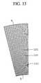
- FIG. 13shows an alternative laminated sector adsorber for the rotor of FIG. 9, with the adsorbent sheets parallel to the axis of the rotor.
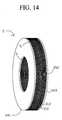
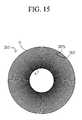
- FIGS. 14 and 15show an alternative radial flow adsorber wheel configuration, with the adsorbent sheets provided as annular discs.
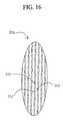
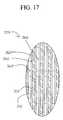
- FIGS. 16 and 17show details of adsorbent laminate spacer configurations.
- FIG. 18shows layering of the adsorbents selected between the first and second ends of the adsorbers.
- FIGS. 19 and 20show alternative spiral wrapped axial flow laminate adsorbers.
- FIG. 25shows a detail of adsorbent sheets assembled from zeolite-coated strips of aluminum foil, stacked so as to define macropore channels between adjacent strips, the macropore channels being substantially straight and orthogonal to the surface of the adsorbent sheet contacting the main flow channels.
- FIGS. 1 and 2are identical to FIGS. 1 and 2
- FIG. 1represents each 180° side of a rotor according to the invention.
- the horizontal axis 15indicates time, with the PSA cycle period defined by the time interval between points 16 and 17 .
- the working pressure in adsorber 3is pressure 18 .
- the cyclebegins as the first end 5 of adsorber 3 is opened by the first valve means 7 to first feed supply means 20 at the first intermediate feed pressure 21 .
- the pressure in that adsorberrises from pressure 18 at time 17 to the first intermediate feed pressure 21 .
- the first end 5is opened next to second feed supply means 22 at the second intermediate feed pressure 23 .
- the adsorber pressurerises to the second intermediate feed pressure.
- the first end 5is opened to a third feed supply means 24 at the higher pressure of the PSA process.
- its second end 6is opened by the second valve means to light product delivery conduit 25 to deliver purified light product.
- the second end 6is next closed to light product delivery conduit 25 , and is opened to deliver “light reflux” gas (enriched in the less readily adsorbed component, similar to second product gas) by conduit 29 to first light reflux pressure let-down means 30 .
- the light reflux pressure let-down meansmay be an expander with optional heat exchangers such as an inlet heater, or a throttle orifice. All or some of the feed supply means may be feed compression stages.
- One of the feed supply meansmay be an external source, such as the ambient atmosphere for air purification or air separation applications.
- the first end 5 of adsorber 3is then closed by the first valve means, while the second end 6 is opened successively by the second valve means to (a) drop the adsorber pressure to the first cocurrent blowdown pressure 32 while delivering light reflux gas by conduit 33 to second light reflux pressure letdown means 34 , (b) drop the adsorber pressure to the second cocurrent blowdown pressure 36 while delivering light reflux gas by conduit 37 to third light reflux pressure letdown means 38 , and (c) drop the adsorber pressure to the third cocurrent blowdown pressure 40 while delivering light reflux gas by conduit 41 to fourth light reflux pressure letdown means 42 . Second end 6 is then closed for an interval, until the light reflux return steps following the countercurrent blowdown steps.
- the light reflux pressure let-down meansmay be mechanical expansion stages for expansion energy recovery, or may be restrictor orifices or throttle valves for irreversible pressure let-down.
- first end 5is opened to first exhaust means 46 , dropping the adsorber pressure to the first countercurrent blowdown intermediate pressure 48 while releasing “heavy” gas (enriched in the more strongly adsorbed component) to the first exhaust means.
- first end 5is opened to second exhaust means 50 , dropping the adsorber pressure to the second countercurrent blowdown intermediate pressure 52 while releasing “heavy” gas.
- first end 5is opened to third exhaust means 54 , dropping the adsorber pressure to the lower pressure 12 of the PSA process while releasing “heavy” gas.
- the adsorberis then repressurized by light reflux gas after the first end 5 is closed.
- the second end 6is opened (a) to receive light reflux gas by conduit 59 from the third light reflux pressure letdown means 38 to raise the adsorber pressure to the first light reflux pressurization pressure 60 , (b) to receive light reflux gas by conduit 61 from the second light reflux pressure letdown means 34 to raise the adsorber pressure to the second light reflux pressurization pressure 62 , and (c) to receive light reflux gas by conduit 63 from the first light reflux pressure letdown means 30 to raise the adsorber pressure to the third light reflux pressurization pressure 64 .
- the processbegins feed pressurization for the next cycle after time 17 as soon as the third light reflux pressurization step has been concluded.
- Feed compartment 72may be open to several adsorbers simultaneously, and may have a restricted entrance 74 so as to provide a gradual throttling equalization of pressure as each adsorber is opened to feed compartment 72 .
- exhaust flowis delivered by a conduit 80 through an optional surge absorber chamber 81 from an exhaust compartment 82 opening to an exhaust port 83 in first valve means 7 .
- Exhaust compartment 82may be open to several adsorbers simultaneously, and may have a restricted entrance 84 so as to provide a gradual throttling equalization of pressure as each adsorber is opened to exhaust compartment 82 .
- Light reflux exit compartment 92may be open to several adsorbers simultaneously, and may have a restricted entrance 94 so as to provide a gradual throttling equalization of pressure as each adsorber is opened to light reflux exit compartment 92 .
- Light reflux exit compartment 97may be open to several adsorbers simultaneously, and may have a restricted entrance 99 so as to provide a gradual throttling equalization of pressure as each adsorber is opened to light reflux entrance compartment 97 .
- the rate of pressure change in each pressurization or blowdown stepmay thus be restricted by throttling in compartments of the first and second valve means, or by throttling in the ports at first and second ends of the adsorbers, resulting in the typical pressure waveform depicted in FIG. 2 .
- Excessively rapid rates of pressure changewould subject the adsorber to mechanical stress, while also causing flow transients which would tend to increase axial dispersion of the concentration wavefront in the adsorber.
- Pulsations of flow and pressureare minimized by having a plurality of adsorbers simultaneously transiting each step of the cycle, and/or by providing surge absorbers in the conduits connecting to the first and second valve means.
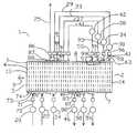
- FIG. 3shows a simplified schematic of a VPSA (vacuum pressure swing adsorption) air separation system 100 , with a mutilstage or split stream centrifugal compressor 101 and a multistage or split stream exhaust vacuum pump 102 .
- the rotary adsorber module 103includes adsorber rotor 2 , and a stator assembly comprising a first valve stator 104 and a second valve stator 105 .
- Rotor 2may be configured for radial flow as suggested in FIG. 3, or for axial flow.
- the compressor 101 and the vacuum pump 102may be rotatably coupled to a suitable drive mechanism, such as a motor 160 .
- First valve stator 108has a plurality of functional compartments in fluid communication to sealing face 107 by ports 109 , including a first feed pressurization supply compartment 111 , a second first feed pressurization supply compartment 112 , a feed production supply compartment 113 at substantially the higher pressure, a first countercurrent blowdown exhaust compartment 114 , a second countercurrent blowdown exhaust compartment 115 , and a purge exhaust compartment 116 at substantially the lower pressure.
- Second valve stator 105includes, with each compartment in fluid communication to sealing face 119 by ports 120 , a light product delivery compartment 121 at substantially the higher pressure, a first light reflux exit compartment 122 which is here simply the downstream end of compartment 121 , a second light reflux exit compartment 123 , a third light reflux exit compartment 124 , a fourth light reflux exit compartment 125 , a fourth light reflux return compartment 126 for purge at substantially the lower pressure, a third light reflux return compartment 127 , a second light reflux return compartment 128 , and a first light reflux return compartment 129 .
- the angular spacing of ports communicating to the compartments in the first and second valve statorsdefines the timing of the PSA cycle steps similar to the cycle of FIG. 2 .
- sealing faces 107 and 119are respectively defined by the outer and inner radii of the annular rotor 2 .
- Fluid sealing between the functional compartments in sealing faceis achieved by clearance seals.
- the clearance sealsare provided as slippers 130 attached to the first and second valve stators by partitions 131 .
- Partitions 131provide static sealing between adjacent compartments.
- Slippers 130engage the sealing faces with narrow fluid sealing clearances, which also provide throttling of gas flows between the adsorbers and functional compartments in each pressure-changing step, so that each adsorber may smoothly equalize in pressure to the pressure of the next functional compartment about to be opened to that adsorber.
- static pressure balancing compartmentse.g.
- the static pressure balancing compartmentsare disposed in angular sectors of the first and second valve stators not used as functional compartments, in order to establish a controlled pressure distribution behind the clearance slippers so as to maintain their positive sealing engagement without excessive contact pressure and consequent friction.
- Apparatus 100has a feed air inlet filter 140 , from which feed air is conveyed through optional dehumidifier 141 and conduit 142 to feed compressor inlet 143 .
- the first intermediate feed pressurization pressureis selected to be substantially atmospheric pressure, so conduit 142 also communicates to first feed pressurization compartment 111 .
- the feed compressor 101has a first discharge port 144 at the second intermediate feed pressurization pressure communicating by conduit 145 and optional dehumidifier 146 to compartment 112 , and a second discharge port 147 at substantially the higher pressure of the cycle pressure communicating by conduit 148 and optional dehumidifier 149 to compartment 113 .
- Exhaust vacuum pump 102has a first inlet port 150 at substantially the lower pressure of the cycle in fluid communication with exhaust compartment 116 , a second inlet port 152 at the second countercurrent blowdown pressure in fluid communication with compartment 115 , and a third inlet port 153 at the first countercurrent blowdown pressure in fluid communication with compartment 114 .
- Vacuum pump 102compresses the combined exhaust and countercurrent blowdown gas as the second product gas enriched in the more readily adsorbed component to substantially atmospheric pressure, and discharges the second product gas from discharge port 154 .
- throttle valves 160provide pressure let-down for each of four light reflux stages, respectively between light reflux exit and return compartments 122 and 129 , 123 and 128 , 124 and 127 , and 125 and 126 as illustrated.
- Actuator means 165is provided to adjust the orifices of the throttle valves.
- FIG. 4shows an axial flow rotary PSA module 200 , particularly suitable for smaller scale oxygen generation.
- the flow path in adsorbers 3is now parallel to axis 201 .
- the steps of the process and functional compartmentsare still in the same angular relationship regardless of a radial or axial flow direction in the adsorbers.
- FIGS. 5, 6 and 7are cross sections of module 200 in the planes respectively defined by arrows 202 - 203 , 204 - 205 , and 206 - 207 .
- FIG. 4is an axial section of module 200 through compartments 113 and 121 at the higher pressure, and compartments 126 and 117 at the lower pressure.
- the adsorber rotor 2contains the “N” adsorbers 3 in adsorber wheel 208 , and revolves between the first valve stator 103 and the second valve stator 105 . Compressed feed air is supplied to compartment 113 as indicated by arrow 211 , while nitrogen enriched exhaust gas is exhausted from compartment 117 as indicated by arrow 212 .
- circumferential seals 215 and 216bound first sealing face 107
- circumferential seals 217 and 218bound second sealing face 119 .
- the sealing facesare flat discs.
- the circumferential sealsalso define the ends of clearance slippers 130 in the sealing faces between the functional compartments.
- Rotor 2is supported by bearing 220 in housing 225 , which is integrally assembled with the first and second valve stators.
- Rotor 2is driven by rim drive motor 230 , which may have a friction, geared or belt engagement with the outer rim of rotor 2 .
- a split stream light reflux expander 240is provided to provide pressure let-down of four light reflux stages with energy recovery.
- the light reflux expanderprovides pressure let-down for each of four light reflux stages, respectively between light reflux exit and return compartments 122 and 129 , 123 and 128 , 124 and 127 , and 125 and 126 as illustrated.
- Light reflux expander 240is coupled to a light product pressure booster compressor 245 by drive shaft 246 .
- Compressor 245receives the light product from conduit 25 , and delivers light product (compressed to a delivery pressure above the higher pressure of the PSA cycle) to delivery conduit 250 . Since the light reflux and light product are both enriched oxygen streams of approximately the same purity, expander 240 and light product compressor 245 may be hermetically enclosed in a single housing. This configuration of a “turbocompressor” oxygen booster without a separate drive motor is advantageous, as a useful pressure boost of the product oxygen can be achieved without an external motor and corresponding shaft seals, and can also be very compact when designed to operate at very high shaft speeds.
- FIG. 5shows the first valve face of embodiment 200 of FIG. 3, at section 202 to 203 , with fluid connections to a multistage or split stream feed compressor 101 and to a multistage or split stream countercurrent blowdown expander 260 as in FIG. 4 .
- Arrow 270indicates the direction of rotation by adsorber rotor 2 .
- the open area of valve face 107 ported to the feed and exhaust compartmentsis indicated by clear angular segments 111 to 217 corresponding to those functional compartments, between circumferential seals 215 and 216 .
- the substantially closed area of valve face 107 between functional compartmentsis indicated by cross-hatched sectors 275 and 276 which are clearance slippers 130 .
- Typical closed sector 275provides a transition for an adsorber, between being open to compartment 114 and open to compartment 115 .
- Gradual openingis provided by a tapering clearance channel between the slipper and the sealing face, so as to achieve gentle pressure equalization of an adsorber being opened to a new compartment.
- Much wider closed sectors(e.g. 276 ) are provided to substantially close flow to or from one end of the adsorbers when pressurization or blowdown is being performed from the other end.
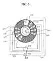
- FIG. 6shows the second valve face of embodiment 200 of FIG. 3, at section 204 to 205 , with fluid connections to a split stream light reflux expander 240 and light product booster compressor 245 as in FIG. 5 .
- Fluid sealing principles and alternativesare similar to those of FIG. 5 . Similar principles and alternatives apply to radial flow and axial flow geometries, respectively sealing on cylindrical or disc faces.
- FIG. 7shows an adsorber wheel configuration for the embodiment of FIG. 4, at section 206 - 207 .
- the adsorbers 3are mounted between outer wall 280 and inner wall 281 of adsorber wheel 208 .
- Each adsorbercomprises a rectangular flat pack of adsorbent sheets 282 , with spacers 283 between the sheets to define flow channels here in the axial direction.
- Separators 284are provided between the adsorbers to fill void space and prevent leakage between the adsorbers.
- the adsorbent sheetscomprise adsorbent material coupled to a reinforcement material.
- a suitable bindermay be used to attach the adsorbent material to the reinforcement material.
- the reinforcement materialmay comprise, for example, a mineral fiber matrix, (such as a glass fiber matrix), a metal wire matrix (such as a wire mesh screen), or a metal foil (such as aluminum foil), which can be anodized.
- glass fiber matricesinclude woven and non-woven glass fiber scrims.
- the adsorbent materialtypically comprises X, A or chabazite type zeolites, typically exchanged with lithium, calcium, strontium, magnesium and/or other cations, and with optimized silicon/aluminum ratios as well known in the art.
- the zeolite crystalsare bound with silica, clay and other binders, or self-bound, within an adsorbent sheet matrix.
- Satisfactory adsorbent sheetshave been made by coating a slurry of zeolite crystals with binder constituents onto the reinforcement material, with successful examples including nonwoven fiber glass scrims, woven metal fabrics, and expanded aluminum foils.
- Spacersare provided by printing or embossing the adsorbent sheet with a raised pattern, or by placing a fabricated spacer between adjacent pairs of adsorbent sheets.
- Alternative satisfactory spacershave been provided as woven metal screens, non-woven fiber glass scrims, and metal foils with etched flow channels in a photolithographic pattern.
- Typical experimental sheet thicknesseshave been 150 microns, with spacer heights in the range of 100 to 150 microns, and adsorber flow channel length approximately 20 cm.
- excellent performancehas been achieved in oxygen separation from air at PSA cycle frequencies in the range of 30 to 150 cycles per minute.
- FIG. 8shows an alternative configuration of rotor 208 , in which the adsorbers 3 are again formed of a pack of rectangular adsorbent sheets with spacers, but with the sheets here curved to circular arcs rather than flat. Voids between the circularly curved adsorber packs are filled by separators 284 .
- Such circularly curved adsorber packsmay be made by forming the adsorbent sheets with spacers in a spiral roll on a circular cylindrical mandrel, and then slitting the spiral roll longitudinally to obtain the desired packs.
- Packing densitycould be further improved by forming the adsorber packs to a spiral rather than circular curve, for example by a pleating technique, or by longitudinally cutting a spiral roll formed on a noncircular mandrel whose shape in two to four identical angular sectors defines the desired spiral.
- FIG. 9shows an enlarged view of the radial flow rotor 2 of FIG. 3 .
- the adsorbers 3are contained in trapezoidal angular sectors between radial partitions 301 .
- Partitions 301are attached to outer rotor shell 303 and inner rotor shell 304 .
- Outer shell 303engages sealing face 107 and is perforated with apertures 106 communicating with the first ends 5 of adsorbers 3 .
- Inner shell 304engages sealing face 119 and is perforated with apertures 118 communicating with the second ends 6 of adsorbers 3 .
- An important advantage of this geometryis the tapering of the adsorbers from the first to second ends of the flow path, thus reducing feed flow velocity and pressure drop adjacent the first end 5 .
- FIGS. 10 and 11show a laminated sector adsorber for the rotor of FIG. 9, with the adsorbent sheets normal to the axis of the rotor.
- the flat adsorbent sheets 310are separated by spacers 311 to define flow channels 312 between first end 5 and second end 6 .
- Sheets 310are on edges 320 to fit the trapezoidal shape of adsorbers 3 between partitions 301 .
- radial spacers 325define radially tapered channels 312 .
- Spacers 325may be printed onto the adsorbent sheets, and may have the structure shown in FIG. 16 . Alternative spacer geometries based on FIGS.
- FIG. 12shows an axial section of the radial flow rotor of FIG. 9, with the sector adsorber of FIG. 10 and showing the adsorbent sheets installed between pressure containment walls 330 and 331 .
- FIG. 13shows an alternative laminated sector adsorber for the rotor of FIG. 9, with the adsorbent sheets in radial planes parallel to the axis of the rotor. Rectangular adsorbent sheets 341 and/or the spacers defining channels 342 are tapered so that the combination of an adsorbent sheet and the adjacent channel has a constant angular width.
- FIGS. 14 and 15show an alternative radial flow adsorber wheel configuration, with the adsorbent sheets provided as complete annular discs and installed between pressure containment walls 340 .
- radial spacers 325define flow channels 312 .
- the spacers of FIG. 15substantially prevent transverse flow between adjacent channels, which thus each define very narrow adsorbers.
- FIGS. 16 and 17show details of adsorbent laminate spacer configurations from zone 350 of FIG. 14 .
- spacer ridges 331are formed by calendering or by printing one of both sides of adsorbent sheets 310 .
- spacers 331are aligned between adjacent sheets so as to provide compressive strength and stability.
- the adsorbentis applied as coating layers 360 to both sides of a support aluminum foil 361 whose surface has been anodized for good adhesion. Spacers 362 are printed or embossed on the coated foil.
- FIG. 18shows layering of the adsorbents selected between the first and second ends of the adsorbers in a radial flow configuration. Similar axial layering may be applied to axial flow embodiments of the invention. From first end 5 to second end 6 of the adsorbers, the flow path passes through first zone 401 , second zone 402 and third zone 403 of the adsorbent.
- the first zone adsorbentmay be alumina gel, silica gel or 13-X zeolite for water vapour removal.
- the second zone adsorbentmay be highly lithium exchanged low silica X zeolite for most efficient bulk nitrogen removal.
- the third zone adsorbentmay advantageously be magnesium, calcium or strontium exchanged chabazite or low silica zeolite X or zeolite A, for most efficient removal of nitrogen from lower concentrations.
- the second zone adsorbentmay be 13-X zeolite for efficient bulk carbon dioxide removal.
- the third zone adsorbentmay advantageously be calcium or strontium exchanged chabazite or low silica X zeolite, for efficient removal of carbon monoxide and any nitrogen.
- the zones of different adsorbent composition between the first and second ends of the adsorbent elementsmay be provided by coating the adsorbent sheets in bands of different composition prior to assembly of the elements, or by assembling the elements from separate sheets of the respective compositions so that the gas flowing along the flow path encounters different sheets coated with the respective composition between the first and second ends.
- FIGS. 19 and 20are identical to FIGS. 19 and 20.
- FIGS. 19 and 20show alternative spiral wrapped axial flow laminate adsorber modules.
- the FIG. 19 configuration of a spiral wound adsorber wheel with one or a few laminate sheets rolled around hub 411is suitable for axial flow only.
- the FIG. 20 configuration of a steep spiral roll of a very large number of adsorbent sheet leavesmay in principle be used for either axial or radial embodiments.
- Each of these geometriesmay use ribbed spacers such as the spacers 331 of FIG. 16 to isolate the flow channels against transverse flow, so that each flow channel may be an independent adsorber from a neighbouring flow channel ported separately to the first and second valve faces.
- the spiral adsorber module of FIG. 19is contained within cylindrical pressure shell 410 , and is rolled around central core 411 . Adjacent adsorbent sheet layers 412 and 413 of the spiral roll are separated by spacers 414 to define the flow channels. In order to define a plurality of distinct adsorbers within the module as angularly spaced sectors of the roll, with these adsorbers to be operated with their respective pressure swing adsorption cycles phased apart according to their relative angular position, some of the spacers must block the channel completely against transverse flow (between adjacent adsorber sectors) through the boundary between those adsorbers.
- FIG. 19illustrates an embodiment with 16 separate adsorbers occupying equal angular sectors within a single cylindrical vessel 410 .
- This aspect of the inventionis usefully applicable without limitation to the case that the vessel 410 is rotating to provide the valving function, and alternatively to the case of a non-rotating vessel 410 containing multiple adsorbers whose pressure swing cycle may be controlled by rotating multiport valves.
- the multileaf spiral adsorber module of FIG. 20has adjacent spirally curved adsorbent sheet layers 420 and 421 of the spiral roll, separated by spacers 422 to define the flow channels.
- FIGS. 21, 22 and 23are identical to FIGS. 21, 22 and 23.
- FIGS. 21, 22 and 23show alternative spacers for use in adsorbers or adsorber sections not requiring compartmentalization against transverse flow, for example the embodiments of FIGS. 7, 8 and 13 .
- the direction of flowis defined by arrow 501 .
- raised spacers 505are applied by printing, to define flow passages 510 between the spacers.
- woven spacers of wire screenare used.
- the mesh of FIG. 22is a diagonal weave of wires 520 .
- the mesh of FIG. 23is a Dutch weave, with fine stabilizing wires 531 and 532 criss-crossing heavier longitudinal spacer wires 533 in the flow direction. Some or all of the stabilizing wires may be replaced by polymer fibres which are burnt out during adsorbent activation.
- FIG. 24shows an angularly narrow portion of an alternative laminated sector adsorber for the rotor of FIG. 9, with a group of adsorbent sheets parallel to the axis of the rotor, and with radial tapering provided by interspersing adsorbent sheets of differing width in the radial direction.
- Adsorbent sheets 601 , 602 , 603 , 604 , 605 and 606have printed spacers 610 between adjacent pairs of the sheets, to establish flow channels in the radial direction between first end 5 and second end 6 . Spacers 610 are printed in a pattern such as that shown in FIG. 21 .
- adsorbent sheetsWhile some of the adsorbent sheets ( 601 , 602 , 603 and 604 ) extend the entire radial distance between the first and second ends, others ( 605 and 606 ) extend from the first end 5 only varying fractions of the radial distance to the second end 6 .
- sheet 606has only approximately a third of the radially extending width, and sheet 605 two thirds of the radially extending width, as the other sheets 601 to 604 . Since the stack of adsorbent sheets is thicker at the first end than at the second, it can be tapered by appropriately selecting the fraction of sheets to have reduced radial widths, so as to have an approximately constant angular width between the first and second ends.
- the sheetsare flexible so as to flex around the terminations 611 and 612 of sheets 606 and 605 , so as to minimize disturbances of flow distribution and channel pressure resistance adjacent the sheet terminations.
- FIG. 25shows a detail portion of two adjacent adsorbent sheets 701 and 702 assembled from zeolite-coated strips of aluminum foil, stacked so as to define macropore channels between adjacent strips, the macropore channels being substantially rectilinear and orthogonal to the surface of the adsorbent sheet contacting the main flow channels.
- An adsorbent sheet (e.g. 100 to 250 microns thick) 701may be assembled from strips 703 of aluminum foil of approximately 12 microns thickness (equivalent to cigarette wrapper foil).
- the foilis slit into strips whose width is nominally equal to the final thickness of the sheet.
- the stripsare preferably anodized for good adhesion of zeolite, and are coated on each side with a coating layer 704 or film of zeolite crystals approximately 4 to 6 microns thick.
- the zeolite crystalsmay be grown in situ from a zeolite synthesis solution, as with the known art of depositing crystalline zeolite films for membranes, although here there is no concern about avoiding minor crevices or pinholes through the zeolite film.
- the zeolite coatingsmay be formed by conversion of a metakaolin coating applied to the foil.
- the zeolite crystalsmay be formed separately, and then attached by binders (e.g. clay or silica) to the anodized sheet.
- binderse.g. clay or silica
- the stripsare then stacked on each other on contacting faces 705 , with their edges in contact with parallel longitudinal support members 706 for sheet 701 and members 707 for sheet 702 , orthogonal to the strips so as to form the adsorbent sheets, constituted by the stacked strips being retained by the parallel longitudinal support members to retain the strips and provide structural integrity.
- the edges of the stacked strips on the longitudinal support membersdefine a wall of the adsorbent material, this wall being the surface of the adsorbent sheet assembled from the strips.
- the adsorbent sheetsare then stacked to form a parallel passage adsorber, with the parallel longitudinal support members serving as spacer members defining flow channels with flow direction indicated by arrows 708 and 709 , orthogonal to the strips and between adjacent pairs of adsorbent sheets.
- the parallel longitudinal support members 706are separated tranversely so as provide open flow channels, while providing support to the zeolite coated strips 704 constituting each sheet.
- these faces 705also define narrow channels penetrating the wall of adsorbent material, and serving as macropores for diffusional access to the zeolite crystallites from the flow channels. These macropores are substantially rectilinear, and they are orthogonal both to the wall and to the flow direction in the adsorber.
- the zeolite crystal coating on the aluminum stripswill have a granular surface texture, so that sufficient voidage will exist between the contacting zeolite surfaces of adjacent coated strips to provide adequate macropore voidage and connectivity, with direct fluid access from the flow channels.
- This voidage between zeolite films of adjacent stripsserves as primary macropore channels 705 , which are substantially straight with minimal tortuosity, and are orthogonal to the surface of the adsorbent sheets contacting the flow channels.
Landscapes
- Chemical & Material Sciences (AREA)
- Engineering & Computer Science (AREA)
- Analytical Chemistry (AREA)
- General Chemical & Material Sciences (AREA)
- Oil, Petroleum & Natural Gas (AREA)
- Chemical Kinetics & Catalysis (AREA)
- Separation Of Gases By Adsorption (AREA)
Abstract
Description
Claims (92)
Priority Applications (4)
| Application Number | Priority Date | Filing Date | Title |
|---|---|---|---|
| EP00938399AEP1189677B1 (en) | 1999-06-09 | 2000-06-09 | Adsorption element |
| US09/591,275US6406523B1 (en) | 1999-06-09 | 2000-06-09 | Rotary pressure swing adsorption apparatus |
| PCT/CA2000/000693WO2000076628A1 (en) | 1999-06-09 | 2000-06-09 | Rotary pressure swing adsorption apparatus |
| AU53812/00AAU5381200A (en) | 1999-06-09 | 2000-06-09 | Rotary pressure swing adsorption apparatus |
Applications Claiming Priority (2)
| Application Number | Priority Date | Filing Date | Title |
|---|---|---|---|
| CA002274286ACA2274286A1 (en) | 1999-06-09 | 1999-06-09 | Rotary pressure swing adsorption apparatus |
| US09/591,275US6406523B1 (en) | 1999-06-09 | 2000-06-09 | Rotary pressure swing adsorption apparatus |
Publications (1)
| Publication Number | Publication Date |
|---|---|
| US6406523B1true US6406523B1 (en) | 2002-06-18 |
Family
ID=25680996
Family Applications (1)
| Application Number | Title | Priority Date | Filing Date |
|---|---|---|---|
| US09/591,275Expired - LifetimeUS6406523B1 (en) | 1999-06-09 | 2000-06-09 | Rotary pressure swing adsorption apparatus |
Country Status (4)
| Country | Link |
|---|---|
| US (1) | US6406523B1 (en) |
| EP (1) | EP1189677B1 (en) |
| AU (1) | AU5381200A (en) |
| WO (1) | WO2000076628A1 (en) |
Cited By (149)
| Publication number | Priority date | Publication date | Assignee | Title |
|---|---|---|---|---|
| US20020004157A1 (en)* | 1998-09-14 | 2002-01-10 | Keefer Bowie G. | Electrical current generation system |
| US20020127442A1 (en)* | 2000-12-08 | 2002-09-12 | Connor Denis J. | Methods and apparatuses for gas separation by pressure swing adsorption with partial gas product feed to fuel cell power source |
| US20020142208A1 (en)* | 2000-10-30 | 2002-10-03 | Keefer Bowie G. | Energy efficient gas separation for fuel cells |
| US20020170436A1 (en)* | 2001-01-05 | 2002-11-21 | Keefer Bowie G. | Adsorbent coating compositions, laminates and adsorber elements comprising such compositions and methods for their manufacture and use |
| US6533846B1 (en)* | 1999-06-10 | 2003-03-18 | Questair Technologies, Inc. | Modular pressure swing adsorption apparatus with clearance-type valve seals |
| US20030143448A1 (en)* | 2000-10-30 | 2003-07-31 | Questair Technologies Inc. | High temperature fuel cell power plant |
| US20030205131A1 (en)* | 2002-03-08 | 2003-11-06 | Golden Catherine Marie Anne | Multilayered adsorbent system for gas separations by pressure swing adsorption |
| US20040005492A1 (en)* | 2002-03-14 | 2004-01-08 | Questair Technologies, Inc. | Hydrogen recycle for solid oxide fuel cell |
| US20040011198A1 (en)* | 2002-03-14 | 2004-01-22 | Questair Technologies, Inc. | Gas separation by combined pressure swing and displacement purge |
| USRE38493E1 (en) | 1996-04-24 | 2004-04-13 | Questair Technologies Inc. | Flow regulated pressure swing adsorption system |
| US20040101742A1 (en)* | 2002-11-27 | 2004-05-27 | Haskell Simpkins | Compliant current collector for fuel cell anode and cathode |
| US20040197612A1 (en)* | 2003-02-26 | 2004-10-07 | Questair Technologies Inc. | Hydrogen recycle for high temperature fuel cells |
| US20040197616A1 (en)* | 2003-04-01 | 2004-10-07 | Edlund David J. | Oxidant-enriched fuel cell system |
| US20040215052A1 (en)* | 2003-04-23 | 2004-10-28 | Gotz Kullik | Incubator with oxygen metering |
| WO2004067684A3 (en)* | 2003-01-30 | 2004-11-25 | Questair Technologies Inc | Compact synthesis gas generation system |
| US20040261618A1 (en)* | 2000-12-11 | 2004-12-30 | Questair Technologies Inc. | PSA with adsorbents sensitive to contaminants |
| WO2005032694A1 (en)* | 2003-09-29 | 2005-04-14 | Questair Technologies Inc. | High density adsorbent structures |
| US20050150378A1 (en)* | 2004-01-12 | 2005-07-14 | Dunne Stephen R. | Adsorption process for continuous purification of high value gas feeds |
| US20050213514A1 (en)* | 2004-03-23 | 2005-09-29 | Ching-Fong Su | Estimating and managing network traffic |
| US20050284291A1 (en)* | 2004-06-29 | 2005-12-29 | Questair Technologies Inc., | Adsorptive separation of gas streams |
| US20060048648A1 (en)* | 2004-08-20 | 2006-03-09 | Questair Technologies Inc. | Parallel passage contactor structure |
| US20060076270A1 (en)* | 2004-10-07 | 2006-04-13 | Poshusta Joseph C | Desulfurization method, apparatus, and materials |
| US20060090646A1 (en)* | 2004-11-04 | 2006-05-04 | Questair Technologies Inc. | Adsorbent material for selective adsorption of carbon monoxide and unsaturated hydrocarbons |
| US20060130650A1 (en)* | 2004-12-20 | 2006-06-22 | Givens James A | Temperature-based breakthrough detection and pressure swing adsorption systems and fuel processing systems including the same |
| US20060130651A1 (en)* | 2004-12-22 | 2006-06-22 | Bizjak Travis A | Systems and methods for regulating heating assembly operation through pressure swing adsorption purge control |
| US20060130402A1 (en)* | 2004-12-17 | 2006-06-22 | Texaco Inc. | Apparatus and methods for producing hydrogen |
| US20060137245A1 (en)* | 2004-12-17 | 2006-06-29 | Texaco Inc. | Apparatus and method for producing hydrogen |
| WO2006079025A1 (en) | 2005-01-21 | 2006-07-27 | Exxonmobil Research And Engineering Company | Management of hydrogen in hydrogen-containing streams from hydrogen sources with rapid cycle pressure swing adsorption |
| US20060169142A1 (en)* | 2005-01-07 | 2006-08-03 | Questair Technologies Inc. | Engineered adsorbent structures for kinetic separation |
| US20060174764A1 (en)* | 2005-01-21 | 2006-08-10 | Narasimhan Sundaram | Integration of rapid cycle pressure swing adsorption with refinery process units (hydroprocessing, hydrocracking, etc.) |
| US20060182680A1 (en)* | 2000-10-27 | 2006-08-17 | Questair Technologies Inc. | Systems and processes for providing hydrogen to fuel cells |
| US20060225349A1 (en)* | 2005-03-29 | 2006-10-12 | Krause Curtis L | Process and apparatus for thermally integrated hydrogen generation system |
| US20070125228A1 (en)* | 2005-11-18 | 2007-06-07 | Questair Technologies Inc. | Rapid cycle syngas pressure swing adsorption system |
| US7250150B1 (en)* | 1999-06-10 | 2007-07-31 | Questair Technology, Inc. | Chemical reactor with pressure swing adsorption |
| US7285350B2 (en) | 2002-09-27 | 2007-10-23 | Questair Technologies Inc. | Enhanced solid oxide fuel cell systems |
| US20070261551A1 (en)* | 2004-11-05 | 2007-11-15 | Sawada James A | Separation Of Carbon Dioxide From Other Gases |
| US20070289445A1 (en)* | 2006-06-15 | 2007-12-20 | Mei Hua | Compact and efficient pressure swing oxygen concentrator |
| US20080005964A1 (en)* | 2004-12-17 | 2008-01-10 | Texaco Inc. | Apparatus and method for controlling compressor motor speed in a hydrogen generator |
| US20080005963A1 (en)* | 2004-12-17 | 2008-01-10 | Texaco Inc. | Apparatus and methods for producing hydrogen |
| US7326277B1 (en) | 2004-04-14 | 2008-02-05 | Uop Llc | Brake air drying using low pressure desiccant wheel |
| US20080028933A1 (en)* | 2006-08-07 | 2008-02-07 | Ross David A | Radial sieve module |
| US20080148935A1 (en)* | 2004-12-20 | 2008-06-26 | Idatech, Llc | Temperature-based breakthrough detection and pressure swing adsorption systems and fuel processing systems including the same |
| US20080276804A1 (en)* | 2005-03-11 | 2008-11-13 | Abdelhamid Sayari | Functionalized Adsorbent for Removal of Acid Gases and Use Thereof |
| US20080277317A1 (en)* | 2005-01-21 | 2008-11-13 | Benoit Touffait | Two Stage Hydrotreating of Distillates with Improved Hydrogen Management |
| US20080282892A1 (en)* | 2007-05-18 | 2008-11-20 | Deckman Harry W | Low mesopore adsorbent contactors for use in swing adsorption processes |
| US20080282887A1 (en)* | 2007-05-18 | 2008-11-20 | Chance Ronald R | Removal of CO2, N2, and H2S from gas mixtures containing same |
| US20080282884A1 (en)* | 2007-05-18 | 2008-11-20 | Kelley Bruce T | Removal of heavy hydrocarbons from gas mixtures containing heavy hydrocarbons and methane |
| US20080282885A1 (en)* | 2007-05-18 | 2008-11-20 | Deckman Harry W | Removal of CO2, N2, or H2S from gas mixtures by swing adsorption with low mesoporosity adsorbent contactors |
| US20080282886A1 (en)* | 2007-05-18 | 2008-11-20 | Reyes Sebastian C | Process for removing a target gas from a mixture of gases by swing adsorption |
| US20080282888A1 (en)* | 2007-05-18 | 2008-11-20 | Deckman Harry W | Temperature swing adsorption of CO2 from flue gas using a parallel channel contractor |
| US20080314245A1 (en)* | 2007-05-18 | 2008-12-25 | Frank Hershkowitz | Process for removing a target gas from a mixture of gases by thermal swing adsorption |
| US20090007782A1 (en)* | 2005-01-21 | 2009-01-08 | Stern David L | Hydrogen Management in Petrochemical Process Units |
| US20090151560A1 (en)* | 2007-12-12 | 2009-06-18 | Idatech, Llc | Systems and methods for supplying auxiliary fuel streams during intermittent byproduct discharge from pressure swing adsorption assemblies |
| US20090151249A1 (en)* | 2007-12-12 | 2009-06-18 | Adams Patton M | Systems and methods for supplying auxiliary fuel streams during intermittent byproduct discharge from pressure swing adsorption assemblies |
| US20090170967A1 (en)* | 2007-12-28 | 2009-07-02 | Lixin You | Concurrent oxidation and steam methane reforming process and reactor therefor |
| US20090165368A1 (en)* | 2007-12-28 | 2009-07-02 | Yunquan Liu | Process and apparatus for reforming gaseous and liquid fuels |
| US20090165385A1 (en)* | 2007-12-28 | 2009-07-02 | Lixin You | Counter-current oxidation and steam methane reforming process and reactor therefor |
| US20090292030A1 (en)* | 2008-05-21 | 2009-11-26 | Daniel Glenn Casey | Process and apparatus for synthesis gas and hydrocarbon production |
| US20090308759A1 (en)* | 2008-06-13 | 2009-12-17 | Marathon Gtf Technology, Ltd. | Bromine-based method and system for converting gaseous alkanes to liquid hydrocarbons using electrolysis for bromine recovery |
| US7674941B2 (en) | 2004-04-16 | 2010-03-09 | Marathon Gtf Technology, Ltd. | Processes for converting gaseous alkanes to liquid hydrocarbons |
| US20100108571A1 (en)* | 2005-01-21 | 2010-05-06 | Exxonmobil Research And Engineering Co. | Hydrotreating process with improved hydrogen management |
| US7838708B2 (en) | 2001-06-20 | 2010-11-23 | Grt, Inc. | Hydrocarbon conversion process improvements |
| US7847139B2 (en) | 2003-07-15 | 2010-12-07 | Grt, Inc. | Hydrocarbon synthesis |
| WO2011008340A1 (en)* | 2009-06-29 | 2011-01-20 | Uop Llc | Vessel, system, and process for minimizing unequal flow distribution |
| US7880041B2 (en) | 2004-04-16 | 2011-02-01 | Marathon Gtf Technology, Ltd. | Process for converting gaseous alkanes to liquid hydrocarbons |
| US7883568B2 (en) | 2006-02-03 | 2011-02-08 | Grt, Inc. | Separation of light gases from halogens |
| US20110031103A1 (en)* | 2008-04-30 | 2011-02-10 | Deckman Harry W | Method and Apparatus For Removal Of Oil From Utility Gas Stream |
| US20110059001A1 (en)* | 2008-06-02 | 2011-03-10 | Kelley Bruce T | Monetizing Remote Gas Using High Energy Materials |
| US20110100873A1 (en)* | 2005-01-21 | 2011-05-05 | Viets John W | Hydrocracking of Heavy Feedstocks with Improved Hydrogen Management |
| US7964764B2 (en) | 2003-07-15 | 2011-06-21 | Grt, Inc. | Hydrocarbon synthesis |
| US7998438B2 (en) | 2007-05-24 | 2011-08-16 | Grt, Inc. | Zone reactor incorporating reversible hydrogen halide capture and release |
| US8008535B2 (en) | 2004-04-16 | 2011-08-30 | Marathon Gtf Technology, Ltd. | Process for converting gaseous alkanes to olefins and liquid hydrocarbons |
| US8053616B2 (en) | 2006-02-03 | 2011-11-08 | Grt, Inc. | Continuous process for converting natural gas to liquid hydrocarbons |
| US8173851B2 (en) | 2004-04-16 | 2012-05-08 | Marathon Gtf Technology, Ltd. | Processes for converting gaseous alkanes to liquid hydrocarbons |
| US8198495B2 (en) | 2010-03-02 | 2012-06-12 | Marathon Gtf Technology, Ltd. | Processes and systems for the staged synthesis of alkyl bromides |
| WO2012118736A2 (en) | 2011-03-01 | 2012-09-07 | Exxonmobil Research And Engineering Company | Gas purification process utilizing engineered small particle adsorbents |
| US8273929B2 (en) | 2008-07-18 | 2012-09-25 | Grt, Inc. | Continuous process for converting natural gas to liquid hydrocarbons |
| WO2012161826A1 (en)* | 2011-03-01 | 2012-11-29 | Exxonmobil Upstream Research Company | Methods of removing contaminants from a hydrocarbon stream by swing adsorption and related apparatus and systems |
| US8367884B2 (en) | 2010-03-02 | 2013-02-05 | Marathon Gtf Technology, Ltd. | Processes and systems for the staged synthesis of alkyl bromides |
| US8436220B2 (en) | 2011-06-10 | 2013-05-07 | Marathon Gtf Technology, Ltd. | Processes and systems for demethanization of brominated hydrocarbons |
| WO2013138437A2 (en) | 2012-03-14 | 2013-09-19 | Exxonmobil Research And Engineering Company | Amine treating process for selective acid gas separations |
| US8603221B2 (en) | 2009-05-08 | 2013-12-10 | Uop Llc | Rapid cycle, gas permeable, adsorbent-containing paper containing p-aramid fibrids and zeolite |
| US8642822B2 (en) | 2004-04-16 | 2014-02-04 | Marathon Gtf Technology, Ltd. | Processes for converting gaseous alkanes to liquid hydrocarbons using microchannel reactor |
| WO2014039316A2 (en) | 2012-09-04 | 2014-03-13 | Exxonmobil Research And Engineering Company | Increasing scales, capacities, and/or efficiencies in swing adsorption processes with hydrocarbon gas feeds |
| US8802908B2 (en) | 2011-10-21 | 2014-08-12 | Marathon Gtf Technology, Ltd. | Processes and systems for separate, parallel methane and higher alkanes' bromination |
| US8815050B2 (en) | 2011-03-22 | 2014-08-26 | Marathon Gtf Technology, Ltd. | Processes and systems for drying liquid bromine |
| US8829256B2 (en) | 2011-06-30 | 2014-09-09 | Gtc Technology Us, Llc | Processes and systems for fractionation of brominated hydrocarbons in the conversion of natural gas to liquid hydrocarbons |
| US8852328B2 (en) | 2010-12-16 | 2014-10-07 | Prometheus Technologies, Llc | Rotary fluid processing systems and associated methods |
| US8906138B2 (en) | 2007-11-12 | 2014-12-09 | Exxonmobil Upstream Research Company | Methods of generating and utilizing utility gas |
| US8921637B2 (en) | 2010-11-15 | 2014-12-30 | Exxonmobil Upstream Research Company | Kinetic fractionators, and cycling processes for fractionation of gas mixtures |
| WO2015017240A1 (en) | 2013-07-29 | 2015-02-05 | Exxonmobil Research And Engineering Company | Separation of hydrogen sulfide from natural gas |
| US8986248B2 (en) | 2004-06-23 | 2015-03-24 | Boston Scientific Scimed, Inc. | Cutting balloon and process |
| US9017457B2 (en) | 2011-03-01 | 2015-04-28 | Exxonmobil Upstream Research Company | Apparatus and systems having a reciprocating valve head assembly and swing adsorption processes related thereto |
| US9034079B2 (en) | 2011-03-01 | 2015-05-19 | Exxonmobil Upstream Research Company | Methods of removing contaminants from hydrocarbon stream by swing adsorption and related apparatus and systems |
| US9034078B2 (en) | 2012-09-05 | 2015-05-19 | Exxonmobil Upstream Research Company | Apparatus and systems having an adsorbent contactor and swing adsorption processes related thereto |
| US9067168B2 (en) | 2010-05-28 | 2015-06-30 | Exxonmobil Upstream Research Company | Integrated adsorber head and valve design and swing adsorption methods related thereto |
| US9120049B2 (en) | 2011-03-01 | 2015-09-01 | Exxonmobil Upstream Research Company | Apparatus and systems having a rotary valve assembly and swing adsorption processes related thereto |
| US9162175B2 (en) | 2011-03-01 | 2015-10-20 | Exxonmobil Upstream Research Company | Apparatus and systems having compact configuration multiple swing adsorption beds and methods related thereto |
| US9193641B2 (en) | 2011-12-16 | 2015-11-24 | Gtc Technology Us, Llc | Processes and systems for conversion of alkyl bromides to higher molecular weight hydrocarbons in circulating catalyst reactor-regenerator systems |
| US9206093B2 (en) | 2004-04-16 | 2015-12-08 | Gtc Technology Us, Llc | Process for converting gaseous alkanes to liquid hydrocarbons |
| US9259681B2 (en) | 2013-10-31 | 2016-02-16 | Haldex Brake Products Corporation | Air dryer |
| US9352269B2 (en) | 2011-03-01 | 2016-05-31 | Exxonmobil Upstream Research Company | Apparatus and systems having a rotary valve assembly and swing adsorption processes related thereto |
| US9358493B2 (en) | 2011-03-01 | 2016-06-07 | Exxonmobil Upstream Research Company | Apparatus and systems having an encased adsorbent contactor and swing adsorption processes related thereto |
| US9458367B2 (en) | 2012-03-14 | 2016-10-04 | Exxonmobil Research And Engineering Company | Low temperature transport and storage of amine gas treatment solutions |
| US9675925B2 (en) | 2014-07-25 | 2017-06-13 | Exxonmobil Upstream Research Company | Apparatus and system having a valve assembly and swing adsorption processes related thereto |
| US9713787B2 (en) | 2014-12-10 | 2017-07-25 | Exxonmobil Upstream Research Company | Adsorbent-incorporated polymer fibers in packed bed and fabric contactors, and methods and devices using same |
| US9744521B2 (en) | 2014-12-23 | 2017-08-29 | Exxonmobil Upstream Research Company | Structured adsorbent beds, methods of producing the same and uses thereof |
| US9751041B2 (en) | 2015-05-15 | 2017-09-05 | Exxonmobil Upstream Research Company | Apparatus and system for swing adsorption processes related thereto |
| US20170307307A1 (en)* | 2016-04-26 | 2017-10-26 | Orbital Atk, Inc. | Heat exchangers, weld configurations for heat exchangers and related systems and methods |
| US9861929B2 (en) | 2015-05-15 | 2018-01-09 | Exxonmobil Upstream Research Company | Apparatus and system for swing adsorption processes related thereto |
| WO2018026515A1 (en) | 2016-08-04 | 2018-02-08 | Exxonmobil Research And Engineering Company | Flexible adsorbents for low pressure drop gas separations |
| US10040022B2 (en) | 2015-10-27 | 2018-08-07 | Exxonmobil Upstream Research Company | Apparatus and system for swing adsorption processes related thereto |
| WO2018144588A1 (en)* | 2017-01-31 | 2018-08-09 | Calgon Carbon Corporation | Sorbent devices |
| US10080992B2 (en) | 2015-09-02 | 2018-09-25 | Exxonmobil Upstream Research Company | Apparatus and system for swing adsorption processes related thereto |
| US10220345B2 (en) | 2015-09-02 | 2019-03-05 | Exxonmobil Upstream Research Company | Apparatus and system for swing adsorption processes related thereto |
| US10220346B2 (en) | 2015-10-27 | 2019-03-05 | Exxonmobil Upstream Research Company | Apparatus and system for swing adsorption processes related thereto |
| US10322365B2 (en) | 2015-10-27 | 2019-06-18 | Exxonmobil Upstream Reseach Company | Apparatus and system for swing adsorption processes related thereto |
| US10328382B2 (en) | 2016-09-29 | 2019-06-25 | Exxonmobil Upstream Research Company | Apparatus and system for testing swing adsorption processes |
| CN110127619A (en)* | 2019-05-31 | 2019-08-16 | 温州市康之本制氧科技有限公司 | The efficient oxygen generation system of matrix form integration PSA |
| US10427091B2 (en) | 2016-05-31 | 2019-10-01 | Exxonmobil Upstream Research Company | Apparatus and system for swing adsorption processes |
| US10427089B2 (en) | 2016-05-31 | 2019-10-01 | Exxonmobil Upstream Research Company | Apparatus and system for swing adsorption processes |
| US10427088B2 (en) | 2016-03-18 | 2019-10-01 | Exxonmobil Upstream Research Company | Apparatus and system for swing adsorption processes related thereto |
| WO2019191436A1 (en) | 2018-03-29 | 2019-10-03 | Praxair Technology, Inc. | Characteristics of tunable adsorbents for rate selective separation of nitrogen from methane |
| US10434458B2 (en) | 2016-08-31 | 2019-10-08 | Exxonmobil Upstream Research Company | Apparatus and system for swing adsorption processes related thereto |
| US10449479B2 (en) | 2016-08-04 | 2019-10-22 | Exxonmobil Research And Engineering Company | Increasing scales, capacities, and/or efficiencies in swing adsorption processes with hydrocarbon gas feeds |
| US10549230B2 (en) | 2016-12-21 | 2020-02-04 | Exxonmobil Upstream Research Company | Self-supporting structures having active materials |
| WO2020028845A1 (en)* | 2018-08-02 | 2020-02-06 | Calgon Carbon Corporation | Sorbent devices |
| US10603626B2 (en) | 2016-09-01 | 2020-03-31 | Exxonmobil Upstream Research Company | Swing adsorption processes using zeolite structures |
| US10675615B2 (en) | 2014-11-11 | 2020-06-09 | Exxonmobil Upstream Research Company | High capacity structures and monoliths via paste imprinting |
| US10710053B2 (en) | 2016-12-21 | 2020-07-14 | Exxonmobil Upstream Research Company | Self-supporting structures having active materials |
| US10744449B2 (en) | 2015-11-16 | 2020-08-18 | Exxonmobil Upstream Research Company | Adsorbent materials and methods of adsorbing carbon dioxide |
| US11231225B2 (en)* | 2017-03-28 | 2022-01-25 | Battelle Memorial Institute | Active magnetic regenerative processes and systems employing hydrogen as heat transfer fluid and process gas |
| US11318410B2 (en) | 2018-12-21 | 2022-05-03 | Exxonmobil Upstream Research Company | Flow modulation systems, apparatus, and methods for cyclical swing adsorption |
| US11331620B2 (en) | 2018-01-24 | 2022-05-17 | Exxonmobil Upstream Research Company | Apparatus and system for swing adsorption processes |
| US11376545B2 (en) | 2019-04-30 | 2022-07-05 | Exxonmobil Upstream Research Company | Rapid cycle adsorbent bed |
| US11413567B2 (en) | 2018-02-28 | 2022-08-16 | Exxonmobil Upstream Research Company | Apparatus and system for swing adsorption processes |
| US11433346B2 (en) | 2019-10-16 | 2022-09-06 | Exxonmobil Upstream Research Company | Dehydration processes utilizing cationic zeolite RHO |
| US11655910B2 (en) | 2019-10-07 | 2023-05-23 | ExxonMobil Technology and Engineering Company | Adsorption processes and systems utilizing step lift control of hydraulically actuated poppet valves |
| US11697090B2 (en) | 2018-08-02 | 2023-07-11 | Calgon Carbon Corporation | Sorbent devices |
| US11697580B2 (en) | 2018-08-01 | 2023-07-11 | Calgon Carbon Corporation | Apparatus for hydrocarbon vapor recovery |
| US11872539B2 (en) | 2020-08-31 | 2024-01-16 | Calgon Carbon Corporation | Copper and nitrogen treated sorbent and method for making same |
| US11911743B2 (en) | 2019-04-03 | 2024-02-27 | Calgon Carbon Corporation | Perfluoroalkyl and polyfluoroalkyl sorbent materials and methods of use |
| EP4157487A4 (en)* | 2020-05-29 | 2024-07-10 | Svante Inc. | PARALLEL PASSAGE PROTECTOR WITH ACTIVE LAYERS |
| US12059668B2 (en) | 2020-08-31 | 2024-08-13 | Calgon Carbon Corporation | Copper, iron, and nitrogen treated sorbent and method for making same |
| US12064745B2 (en) | 2020-08-31 | 2024-08-20 | Calgon Carbon Corporation | Iron and nitrogen treated sorbent and method for making same |
| US12076687B2 (en) | 2019-08-08 | 2024-09-03 | Calgon Carbon Corporation | Sorbent devices for air intakes |
| WO2025021927A1 (en)* | 2023-07-26 | 2025-01-30 | Man Energy Solutions Se | Combination of a rotatable pre-drying unit with co2 extraction |
| US12319593B2 (en) | 2020-07-14 | 2025-06-03 | Calgon Carbon Corporation | Sorbents having high volumetric iodine and molasses values for removal of PFAS from fluids and methods of making and using the same |
| US12318758B2 (en) | 2019-07-22 | 2025-06-03 | Calgon Carbon Corporation | Textured sorbent sheets, assemblies containing them, and molds for making same |
Families Citing this family (10)
| Publication number | Priority date | Publication date | Assignee | Title |
|---|---|---|---|---|
| AU2002213120A1 (en)* | 2000-10-10 | 2002-04-22 | Mesosystems Technology | Multiple plate sorption assembly and method for using same |
| EP1690313A4 (en)* | 2003-11-19 | 2008-12-03 | Questair Technologies Inc | High efficiency load-following solid oxide fuel cell systems |
| DE102004024676A1 (en)* | 2004-05-18 | 2005-12-15 | Süd-Chemie AG | Film-type sorbent-containing compositions |
| EP2403926B1 (en) | 2009-03-05 | 2019-10-02 | G4 Insights Inc. | Process for thermochemical conversion of biomass |
| EP2501788A4 (en) | 2009-11-18 | 2013-12-04 | G4 Insights Inc | Sorption enhanced methanation of biomass |
| WO2011060539A1 (en) | 2009-11-18 | 2011-05-26 | G4 Insights Inc. | Method and system for biomass hydrogasification |
| FR2992573B1 (en)* | 2012-06-29 | 2017-10-20 | Air Liquide | ASSEMBLY OF STRUCTURED ADSORBENT MODULES |
| US20230347277A1 (en)* | 2020-01-10 | 2023-11-02 | Xebec Adsorption Inc. | Biogas processing systems and methods |
| CN114247259B (en)* | 2021-12-28 | 2023-11-03 | 湖北中船气体有限公司 | Large radial adsorption tower special for VPSA oxygen production |
| CN119607792B (en)* | 2025-02-17 | 2025-04-18 | 安徽华气气体科技有限公司 | A pressure swing adsorption device for producing high-purity oxygen |
Citations (42)
| Publication number | Priority date | Publication date | Assignee | Title |
|---|---|---|---|---|
| US3176446A (en) | 1963-05-27 | 1965-04-06 | Svenskaflakfabriken Ab | Ceramic gas conditioner |
| US3713281A (en)* | 1971-11-02 | 1973-01-30 | G Asker | Heat and moisture exchange packing |
| US4093435A (en)* | 1973-11-23 | 1978-06-06 | Wing Industries Inc. | Total heat energy exchangers |
| US4290789A (en)* | 1979-03-08 | 1981-09-22 | Wing Industries, Inc. | Total energy exchange apparatus |
| US4354859A (en) | 1981-08-06 | 1982-10-19 | Union Carbide Corporation | Enhanced gas separation by selective adsorption |
| US4452612A (en) | 1982-09-22 | 1984-06-05 | Cubemco, Inc. | Separation and purification of gases and vapors by continuous pressure-swing adsorption |
| EP0143537A2 (en) | 1983-10-03 | 1985-06-05 | Bowie Gordon Keefer | Method and apparatus for gas separation and synthesis |
| US4530705A (en) | 1984-04-16 | 1985-07-23 | Firey Joseph C | Cyclic gas separator |
| US4702903A (en) | 1983-10-03 | 1987-10-27 | Keefer Bowie | Method and apparatus for gas separation and synthesis |
| US4758253A (en) | 1986-02-24 | 1988-07-19 | Imperial Chemical Industries Plc | Adsorption process |
| US4781735A (en) | 1986-12-26 | 1988-11-01 | Osaka Sanso Kogyo Ltd. | Enrichment in oxygen gas |
| US4801308A (en) | 1983-10-03 | 1989-01-31 | Keefer Bowie | Apparatus and process for pressure swing adsorption separation |
| US4816121A (en) | 1983-10-03 | 1989-03-28 | Keefer Bowie | Gas phase chemical reactor |
| US4946479A (en)* | 1987-10-28 | 1990-08-07 | Daikin Industries, Ltd. | Apparatus for solvent recovery |
| US4968329A (en) | 1987-10-26 | 1990-11-06 | Keefer Bowie | Pressure swing adsorption for concentration of a gas component |
| US4969935A (en) | 1988-07-08 | 1990-11-13 | L'air Liquide, Societe Anonyme Pour L'etude Et L'exploitation Des Procedes Georges Claude | Process for treating a gaseous mixture by adsorption |
| US5017202A (en)* | 1989-04-13 | 1991-05-21 | Taikisha Ltd. | Gas treating apparatus |
| US5057128A (en)* | 1990-07-03 | 1991-10-15 | Flakt, Inc. | Rotary adsorption assembly |
| CA2016045A1 (en) | 1990-05-04 | 1991-11-04 | Quest Air Gases Inc. | Gas separation by pressure swing adsorption |
| US5082473A (en) | 1990-07-23 | 1992-01-21 | Keefer Bowie | Extraction and concentration of a gas component |
| CA2087973A1 (en) | 1990-07-23 | 1992-01-24 | Questor Industries Inc. | Adsorptive gas separator with inertial energy exchange |
| US5133784A (en) | 1990-10-11 | 1992-07-28 | L'air Liquide, Societe Anonyme Pour L'etude Et L'exploitation Des Procedes Georges Claude | Process and apparatus for separating a at least a component of a gaseous mixture by adsorption |
| US5246676A (en) | 1991-02-20 | 1993-09-21 | L'air Liquide, Societe Anonyme Pour L'etude Et L'exploitation Des Procedes Georges Claude | Method of producing oxygen by adsorption |
| US5248325A (en) | 1991-05-09 | 1993-09-28 | Mitsubishi Jukogyo Kabushiki Kaisha | Gas separating system and gas recovery system |
| US5256172A (en) | 1992-04-17 | 1993-10-26 | Keefer Bowie | Thermally coupled pressure swing adsorption |
| WO1994004249A1 (en) | 1992-08-18 | 1994-03-03 | Ribesse, Jacques | Method and device for separating gas components by adsorption |
| US5328503A (en) | 1992-11-16 | 1994-07-12 | Air Products And Chemicals, Inc. | Adsorption process with mixed repressurization and purge/equalization |
| US5393326A (en) | 1991-11-26 | 1995-02-28 | L'air Liquide, Societe Anonyme Pour L'etude Et L'exploitation Des Procedes Georges Claude | Process for the production of a gas with a substantial oxygen content |
| US5411578A (en) | 1994-05-10 | 1995-05-02 | Air Products And Chemicals, Inc. | Vacuum swing adsorption process with mixed repressurization and provide product depressurization |
| US5431716A (en)* | 1992-10-01 | 1995-07-11 | Electrolux Leisure Appliances | Sorption device |
| US5441559A (en) | 1992-04-13 | 1995-08-15 | L'air Liquide, Societe Anonyme Pour L'etude Et L'exploitation Des Procedes Georges Claude | Rotatable device for the separation by adsorption of at least one constituent of a gaseous mixture |
| EP0681860A2 (en) | 1994-05-09 | 1995-11-15 | The Boc Group, Inc. | Continuous pressure difference driven adsorption process |
| US5523326A (en) | 1994-10-28 | 1996-06-04 | Uop | PSA process with reaction for reversible reactions |
| US5656067A (en) | 1996-02-23 | 1997-08-12 | Air Products And Chemicals, Inc. | VSA adsorption process with energy recovery |
| US5658370A (en) | 1994-07-18 | 1997-08-19 | L'air Liquide, Societe Anonyme Pour L'etude Et L'exploitation Des Procedes Georges Claude | Process for the separation of nitrogen from a gaseous mixture by adsorption |
| US5711926A (en) | 1996-05-14 | 1998-01-27 | Knaebel; Kent S. | Pressure swing adsorption system for ammonia synthesis |
| US5878590A (en)* | 1998-02-25 | 1999-03-09 | General Motors Corporation | Dehumidifying mechanism for auto air conditioner with improved space utilization and thermal efficiency |
| US5917136A (en) | 1995-10-04 | 1999-06-29 | Air Products And Chemicals, Inc. | Carbon dioxide pressure swing adsorption process using modified alumina adsorbents |
| US6051050A (en)* | 1997-12-22 | 2000-04-18 | Questor Industries Inc. | Modular pressure swing adsorption with energy recovery |
| US6056804A (en) | 1997-06-30 | 2000-05-02 | Questor Industries Inc. | High frequency rotary pressure swing adsorption apparatus |
| US6063161A (en) | 1996-04-24 | 2000-05-16 | Sofinoy Societte Financiere D'innovation Inc. | Flow regulated pressure swing adsorption system |
| US6176897B1 (en) | 1996-12-31 | 2001-01-23 | Questor Industries Inc. | High frequency pressure swing adsorption |
Family Cites Families (1)
| Publication number | Priority date | Publication date | Assignee | Title |
|---|---|---|---|---|
| DE69841332D1 (en)* | 1997-12-01 | 2010-01-07 | Xebec Adsorption Inc | MODULAR PRESSURE CHANGE ADSORPTION DEVICE |
- 2000
- 2000-06-09AUAU53812/00Apatent/AU5381200A/ennot_activeAbandoned
- 2000-06-09WOPCT/CA2000/000693patent/WO2000076628A1/enactiveIP Right Grant
- 2000-06-09EPEP00938399Apatent/EP1189677B1/ennot_activeExpired - Lifetime
- 2000-06-09USUS09/591,275patent/US6406523B1/ennot_activeExpired - Lifetime
Patent Citations (46)
| Publication number | Priority date | Publication date | Assignee | Title |
|---|---|---|---|---|
| US3176446A (en) | 1963-05-27 | 1965-04-06 | Svenskaflakfabriken Ab | Ceramic gas conditioner |
| US3713281A (en)* | 1971-11-02 | 1973-01-30 | G Asker | Heat and moisture exchange packing |
| US4093435A (en)* | 1973-11-23 | 1978-06-06 | Wing Industries Inc. | Total heat energy exchangers |
| US4290789A (en)* | 1979-03-08 | 1981-09-22 | Wing Industries, Inc. | Total energy exchange apparatus |
| US4354859A (en) | 1981-08-06 | 1982-10-19 | Union Carbide Corporation | Enhanced gas separation by selective adsorption |
| US4452612A (en) | 1982-09-22 | 1984-06-05 | Cubemco, Inc. | Separation and purification of gases and vapors by continuous pressure-swing adsorption |
| EP0143537A2 (en) | 1983-10-03 | 1985-06-05 | Bowie Gordon Keefer | Method and apparatus for gas separation and synthesis |
| US4702903A (en) | 1983-10-03 | 1987-10-27 | Keefer Bowie | Method and apparatus for gas separation and synthesis |
| CA1256038A (en) | 1983-10-03 | 1989-06-20 | Bowie Gordon Keefer | Method and apparatus for gas separation and synthesis |
| US4801308A (en) | 1983-10-03 | 1989-01-31 | Keefer Bowie | Apparatus and process for pressure swing adsorption separation |
| US4816121A (en) | 1983-10-03 | 1989-03-28 | Keefer Bowie | Gas phase chemical reactor |
| US4530705A (en) | 1984-04-16 | 1985-07-23 | Firey Joseph C | Cyclic gas separator |
| US4758253A (en) | 1986-02-24 | 1988-07-19 | Imperial Chemical Industries Plc | Adsorption process |
| US4781735A (en) | 1986-12-26 | 1988-11-01 | Osaka Sanso Kogyo Ltd. | Enrichment in oxygen gas |
| US4968329A (en) | 1987-10-26 | 1990-11-06 | Keefer Bowie | Pressure swing adsorption for concentration of a gas component |
| US4946479A (en)* | 1987-10-28 | 1990-08-07 | Daikin Industries, Ltd. | Apparatus for solvent recovery |
| US4969935A (en) | 1988-07-08 | 1990-11-13 | L'air Liquide, Societe Anonyme Pour L'etude Et L'exploitation Des Procedes Georges Claude | Process for treating a gaseous mixture by adsorption |
| US5017202A (en)* | 1989-04-13 | 1991-05-21 | Taikisha Ltd. | Gas treating apparatus |
| CA2016045A1 (en) | 1990-05-04 | 1991-11-04 | Quest Air Gases Inc. | Gas separation by pressure swing adsorption |
| US5057128A (en)* | 1990-07-03 | 1991-10-15 | Flakt, Inc. | Rotary adsorption assembly |
| CA2087973A1 (en) | 1990-07-23 | 1992-01-24 | Questor Industries Inc. | Adsorptive gas separator with inertial energy exchange |
| US5082473A (en) | 1990-07-23 | 1992-01-21 | Keefer Bowie | Extraction and concentration of a gas component |
| CA2087972A1 (en) | 1990-07-23 | 1992-01-24 | Bowie Gordon Keefer | Extraction and concentration of a gas component |
| US5133784A (en) | 1990-10-11 | 1992-07-28 | L'air Liquide, Societe Anonyme Pour L'etude Et L'exploitation Des Procedes Georges Claude | Process and apparatus for separating a at least a component of a gaseous mixture by adsorption |
| US5246676A (en) | 1991-02-20 | 1993-09-21 | L'air Liquide, Societe Anonyme Pour L'etude Et L'exploitation Des Procedes Georges Claude | Method of producing oxygen by adsorption |
| US5248325A (en) | 1991-05-09 | 1993-09-28 | Mitsubishi Jukogyo Kabushiki Kaisha | Gas separating system and gas recovery system |
| US5393326A (en) | 1991-11-26 | 1995-02-28 | L'air Liquide, Societe Anonyme Pour L'etude Et L'exploitation Des Procedes Georges Claude | Process for the production of a gas with a substantial oxygen content |
| US5441559A (en) | 1992-04-13 | 1995-08-15 | L'air Liquide, Societe Anonyme Pour L'etude Et L'exploitation Des Procedes Georges Claude | Rotatable device for the separation by adsorption of at least one constituent of a gaseous mixture |
| CA2109055A1 (en) | 1992-04-17 | 1995-04-23 | Questair Technologies Inc. | Thermally Coupled Pressure Swing Adsorption |
| US5256172A (en) | 1992-04-17 | 1993-10-26 | Keefer Bowie | Thermally coupled pressure swing adsorption |
| WO1994004249A1 (en) | 1992-08-18 | 1994-03-03 | Ribesse, Jacques | Method and device for separating gas components by adsorption |
| US5431716A (en)* | 1992-10-01 | 1995-07-11 | Electrolux Leisure Appliances | Sorption device |
| US5328503A (en) | 1992-11-16 | 1994-07-12 | Air Products And Chemicals, Inc. | Adsorption process with mixed repressurization and purge/equalization |
| EP0681860A2 (en) | 1994-05-09 | 1995-11-15 | The Boc Group, Inc. | Continuous pressure difference driven adsorption process |
| US5487775A (en) | 1994-05-09 | 1996-01-30 | The Boc Group, Inc. | Continuous pressure difference driven adsorption process |
| US5411578A (en) | 1994-05-10 | 1995-05-02 | Air Products And Chemicals, Inc. | Vacuum swing adsorption process with mixed repressurization and provide product depressurization |
| US5658370A (en) | 1994-07-18 | 1997-08-19 | L'air Liquide, Societe Anonyme Pour L'etude Et L'exploitation Des Procedes Georges Claude | Process for the separation of nitrogen from a gaseous mixture by adsorption |
| US5523326A (en) | 1994-10-28 | 1996-06-04 | Uop | PSA process with reaction for reversible reactions |
| US5917136A (en) | 1995-10-04 | 1999-06-29 | Air Products And Chemicals, Inc. | Carbon dioxide pressure swing adsorption process using modified alumina adsorbents |
| US5656067A (en) | 1996-02-23 | 1997-08-12 | Air Products And Chemicals, Inc. | VSA adsorption process with energy recovery |
| US6063161A (en) | 1996-04-24 | 2000-05-16 | Sofinoy Societte Financiere D'innovation Inc. | Flow regulated pressure swing adsorption system |
| US5711926A (en) | 1996-05-14 | 1998-01-27 | Knaebel; Kent S. | Pressure swing adsorption system for ammonia synthesis |
| US6176897B1 (en) | 1996-12-31 | 2001-01-23 | Questor Industries Inc. | High frequency pressure swing adsorption |
| US6056804A (en) | 1997-06-30 | 2000-05-02 | Questor Industries Inc. | High frequency rotary pressure swing adsorption apparatus |
| US6051050A (en)* | 1997-12-22 | 2000-04-18 | Questor Industries Inc. | Modular pressure swing adsorption with energy recovery |
| US5878590A (en)* | 1998-02-25 | 1999-03-09 | General Motors Corporation | Dehumidifying mechanism for auto air conditioner with improved space utilization and thermal efficiency |
Cited By (275)
| Publication number | Priority date | Publication date | Assignee | Title |
|---|---|---|---|---|
| USRE38493E1 (en) | 1996-04-24 | 2004-04-13 | Questair Technologies Inc. | Flow regulated pressure swing adsorption system |
| USRE40006E1 (en)* | 1996-04-24 | 2008-01-22 | Questair Technologies Inc. | Flow regulated pressure swing adsorption system |
| US20020004157A1 (en)* | 1998-09-14 | 2002-01-10 | Keefer Bowie G. | Electrical current generation system |
| US6921597B2 (en) | 1998-09-14 | 2005-07-26 | Questair Technologies Inc. | Electrical current generation system |
| US7758988B2 (en) | 1998-09-14 | 2010-07-20 | Xebec Adsorption Inc. | System that includes a fuel cell and an oxygen gas delivery system |
| US20060257708A1 (en)* | 1998-09-14 | 2006-11-16 | Questair Technologies Inc. | Electrical current generation system |
| US20030157390A1 (en)* | 1998-09-14 | 2003-08-21 | Questair Technologies, Inc. | Electrical current generation system |
| US7687044B2 (en) | 1999-06-10 | 2010-03-30 | Xebec Adsorption Inc. | Chemical reactor with pressure swing adsorption |
| US7250150B1 (en)* | 1999-06-10 | 2007-07-31 | Questair Technology, Inc. | Chemical reactor with pressure swing adsorption |
| US6533846B1 (en)* | 1999-06-10 | 2003-03-18 | Questair Technologies, Inc. | Modular pressure swing adsorption apparatus with clearance-type valve seals |
| US20070253872A1 (en)* | 1999-06-10 | 2007-11-01 | Questair Technologies Inc. | Chemical reactor with pressure swing adsorption |
| US7674539B2 (en) | 2000-10-27 | 2010-03-09 | Xebec Adsorption Inc. | Systems and processes for providing hydrogen to fuel cells |
| US20060182680A1 (en)* | 2000-10-27 | 2006-08-17 | Questair Technologies Inc. | Systems and processes for providing hydrogen to fuel cells |
| US7087331B2 (en) | 2000-10-30 | 2006-08-08 | Questair Technologies Inc. | Energy efficient gas separation for fuel cells |
| US20030143448A1 (en)* | 2000-10-30 | 2003-07-31 | Questair Technologies Inc. | High temperature fuel cell power plant |
| US20020142208A1 (en)* | 2000-10-30 | 2002-10-03 | Keefer Bowie G. | Energy efficient gas separation for fuel cells |
| US7097925B2 (en) | 2000-10-30 | 2006-08-29 | Questair Technologies Inc. | High temperature fuel cell power plant |
| US6866950B2 (en) | 2000-12-08 | 2005-03-15 | Questair Technologies Inc. | Methods and apparatuses for gas separation by pressure swing adsorption with partial gas product feed to fuel cell power source |
| US20020127442A1 (en)* | 2000-12-08 | 2002-09-12 | Connor Denis J. | Methods and apparatuses for gas separation by pressure swing adsorption with partial gas product feed to fuel cell power source |
| US7160367B2 (en) | 2000-12-11 | 2007-01-09 | Questair Technologies, Inc. | PSA with adsorbents sensitive to contaminants |
| US7037358B2 (en) | 2000-12-11 | 2006-05-02 | The Boc Group, Inc. | PSA with adsorbents sensitive to contaminants |
| US20040261618A1 (en)* | 2000-12-11 | 2004-12-30 | Questair Technologies Inc. | PSA with adsorbents sensitive to contaminants |
| US20020170436A1 (en)* | 2001-01-05 | 2002-11-21 | Keefer Bowie G. | Adsorbent coating compositions, laminates and adsorber elements comprising such compositions and methods for their manufacture and use |
| US7300905B2 (en) | 2001-01-05 | 2007-11-27 | Questair Technologies Inc. | Methods for their manufacture of adsorbent |
| US7838708B2 (en) | 2001-06-20 | 2010-11-23 | Grt, Inc. | Hydrocarbon conversion process improvements |
| US8415512B2 (en) | 2001-06-20 | 2013-04-09 | Grt, Inc. | Hydrocarbon conversion process improvements |
| US20030205131A1 (en)* | 2002-03-08 | 2003-11-06 | Golden Catherine Marie Anne | Multilayered adsorbent system for gas separations by pressure swing adsorption |
| US6893483B2 (en) | 2002-03-08 | 2005-05-17 | Air Products And Chemicals, Inc. | Multilayered adsorbent system for gas separations by pressure swing adsorption |
| US6902602B2 (en) | 2002-03-14 | 2005-06-07 | Questair Technologies Inc. | Gas separation by combined pressure swing and displacement purge |
| US7387849B2 (en) | 2002-03-14 | 2008-06-17 | Questair Technologies Inc. | Hydrogen recycle for solid oxide fuel cell |
| US20040005492A1 (en)* | 2002-03-14 | 2004-01-08 | Questair Technologies, Inc. | Hydrogen recycle for solid oxide fuel cell |
| US20040011198A1 (en)* | 2002-03-14 | 2004-01-22 | Questair Technologies, Inc. | Gas separation by combined pressure swing and displacement purge |
| US7285350B2 (en) | 2002-09-27 | 2007-10-23 | Questair Technologies Inc. | Enhanced solid oxide fuel cell systems |
| US8048587B2 (en)* | 2002-11-27 | 2011-11-01 | Delphi Technologies, Inc. | Compliant current collector for fuel cell anode and cathode |
| US20040101742A1 (en)* | 2002-11-27 | 2004-05-27 | Haskell Simpkins | Compliant current collector for fuel cell anode and cathode |
| WO2004067684A3 (en)* | 2003-01-30 | 2004-11-25 | Questair Technologies Inc | Compact synthesis gas generation system |
| US20060090395A1 (en)* | 2003-01-30 | 2006-05-04 | Rode Edward J | Compact synthesis gas generation system |
| US20040197612A1 (en)* | 2003-02-26 | 2004-10-07 | Questair Technologies Inc. | Hydrogen recycle for high temperature fuel cells |
| US20040197616A1 (en)* | 2003-04-01 | 2004-10-07 | Edlund David J. | Oxidant-enriched fuel cell system |
| US20040215052A1 (en)* | 2003-04-23 | 2004-10-28 | Gotz Kullik | Incubator with oxygen metering |
| US7059323B2 (en)* | 2003-04-23 | 2006-06-13 | Dräger Medical AG & Co. KGaA | Incubator with oxygen metering |
| US7847139B2 (en) | 2003-07-15 | 2010-12-07 | Grt, Inc. | Hydrocarbon synthesis |
| US7964764B2 (en) | 2003-07-15 | 2011-06-21 | Grt, Inc. | Hydrocarbon synthesis |
| US20050129952A1 (en)* | 2003-09-29 | 2005-06-16 | Questair Technologies Inc. | High density adsorbent structures |
| WO2005032694A1 (en)* | 2003-09-29 | 2005-04-14 | Questair Technologies Inc. | High density adsorbent structures |
| US20050150378A1 (en)* | 2004-01-12 | 2005-07-14 | Dunne Stephen R. | Adsorption process for continuous purification of high value gas feeds |
| US7166149B2 (en) | 2004-01-12 | 2007-01-23 | Uop Llc | Adsorption process for continuous purification of high value gas feeds |
| US20050213514A1 (en)* | 2004-03-23 | 2005-09-29 | Ching-Fong Su | Estimating and managing network traffic |
| US7326277B1 (en) | 2004-04-14 | 2008-02-05 | Uop Llc | Brake air drying using low pressure desiccant wheel |
| US8642822B2 (en) | 2004-04-16 | 2014-02-04 | Marathon Gtf Technology, Ltd. | Processes for converting gaseous alkanes to liquid hydrocarbons using microchannel reactor |
| US7674941B2 (en) | 2004-04-16 | 2010-03-09 | Marathon Gtf Technology, Ltd. | Processes for converting gaseous alkanes to liquid hydrocarbons |
| US8232441B2 (en) | 2004-04-16 | 2012-07-31 | Marathon Gtf Technology, Ltd. | Process for converting gaseous alkanes to liquid hydrocarbons |
| US8008535B2 (en) | 2004-04-16 | 2011-08-30 | Marathon Gtf Technology, Ltd. | Process for converting gaseous alkanes to olefins and liquid hydrocarbons |
| US7880041B2 (en) | 2004-04-16 | 2011-02-01 | Marathon Gtf Technology, Ltd. | Process for converting gaseous alkanes to liquid hydrocarbons |
| US9206093B2 (en) | 2004-04-16 | 2015-12-08 | Gtc Technology Us, Llc | Process for converting gaseous alkanes to liquid hydrocarbons |
| US8173851B2 (en) | 2004-04-16 | 2012-05-08 | Marathon Gtf Technology, Ltd. | Processes for converting gaseous alkanes to liquid hydrocarbons |
| US8986248B2 (en) | 2004-06-23 | 2015-03-24 | Boston Scientific Scimed, Inc. | Cutting balloon and process |
| US7189280B2 (en) | 2004-06-29 | 2007-03-13 | Questair Technologies Inc. | Adsorptive separation of gas streams |
| US20050284291A1 (en)* | 2004-06-29 | 2005-12-29 | Questair Technologies Inc., | Adsorptive separation of gas streams |
| US20060048648A1 (en)* | 2004-08-20 | 2006-03-09 | Questair Technologies Inc. | Parallel passage contactor structure |
| US7344686B2 (en) | 2004-10-07 | 2008-03-18 | Mesoscopic Devices, Inc. | Desulfurization apparatus with individually controllable heaters |
| US20080289496A1 (en)* | 2004-10-07 | 2008-11-27 | Poshusta Joseph C | Method for removing sulfur or other contaminant species from hydrocarbon fuels or other fuels |
| US7837862B2 (en)* | 2004-10-07 | 2010-11-23 | Protonex Technology, LLC | Method for removing sulfur or other contaminant species from hydrocarbon fuels or other fuels |
| US20060076270A1 (en)* | 2004-10-07 | 2006-04-13 | Poshusta Joseph C | Desulfurization method, apparatus, and materials |
| US20060090646A1 (en)* | 2004-11-04 | 2006-05-04 | Questair Technologies Inc. | Adsorbent material for selective adsorption of carbon monoxide and unsaturated hydrocarbons |
| US7828877B2 (en) | 2004-11-05 | 2010-11-09 | Xebec Adsorption, Inc. | Separation of carbon dioxide from other gases |
| US20070261551A1 (en)* | 2004-11-05 | 2007-11-15 | Sawada James A | Separation Of Carbon Dioxide From Other Gases |
| US20080005963A1 (en)* | 2004-12-17 | 2008-01-10 | Texaco Inc. | Apparatus and methods for producing hydrogen |
| US20080005964A1 (en)* | 2004-12-17 | 2008-01-10 | Texaco Inc. | Apparatus and method for controlling compressor motor speed in a hydrogen generator |
| US20060137245A1 (en)* | 2004-12-17 | 2006-06-29 | Texaco Inc. | Apparatus and method for producing hydrogen |
| US20060130402A1 (en)* | 2004-12-17 | 2006-06-22 | Texaco Inc. | Apparatus and methods for producing hydrogen |
| US7763085B2 (en) | 2004-12-17 | 2010-07-27 | Texaco Inc. | Apparatus for producing hydrogen |
| US7988751B2 (en) | 2004-12-17 | 2011-08-02 | Texaco Inc. | Method for producing hydrogen |
| US7402287B2 (en) | 2004-12-17 | 2008-07-22 | Texaco Inc. | Apparatus and methods for producing hydrogen |
| US7892304B2 (en) | 2004-12-17 | 2011-02-22 | Texaco Inc. | Apparatus and method for controlling compressor motor speed in a hydrogen generator |
| US20080127554A1 (en)* | 2004-12-17 | 2008-06-05 | Texaco Inc. | Apparatus and method for producing hydrogen |
| US7354464B2 (en) | 2004-12-17 | 2008-04-08 | Texaco Inc. | Apparatus and method for producing hydrogen |
| US7354463B2 (en) | 2004-12-17 | 2008-04-08 | Texaco Inc. | Apparatus and methods for producing hydrogen |
| US20080289255A1 (en)* | 2004-12-17 | 2008-11-27 | Texaco Inc. | Apparatus and Method for Producing Hydrogen |
| US20080148935A1 (en)* | 2004-12-20 | 2008-06-26 | Idatech, Llc | Temperature-based breakthrough detection and pressure swing adsorption systems and fuel processing systems including the same |
| US7833311B2 (en) | 2004-12-20 | 2010-11-16 | Idatech, Llc | Temperature-based breakthrough detection and pressure swing adsorption systems and fuel processing systems including the same |
| US20060130650A1 (en)* | 2004-12-20 | 2006-06-22 | Givens James A | Temperature-based breakthrough detection and pressure swing adsorption systems and fuel processing systems including the same |
| US7393382B2 (en) | 2004-12-20 | 2008-07-01 | Idatech Llc | Temperature-based breakthrough detection and pressure swing adsorption systems and fuel processing systems including the same |
| US20060130651A1 (en)* | 2004-12-22 | 2006-06-22 | Bizjak Travis A | Systems and methods for regulating heating assembly operation through pressure swing adsorption purge control |
| US7833326B2 (en) | 2004-12-22 | 2010-11-16 | Idatech, Llc | Systems and methods for regulating heating assembly operation through pressure swing adsorption purge control |
| US20080302011A1 (en)* | 2004-12-22 | 2008-12-11 | Idatech, Llc | Systems and methods for regulating heating assembly operation through pressure swing adsorption purge control |
| US8038771B2 (en) | 2004-12-22 | 2011-10-18 | Idatech, Llc | Systems and methods for regulating heating assembly operation through pressure swing adsorption purge control |
| US7399342B2 (en) | 2004-12-22 | 2008-07-15 | Idatech, Llc | Systems and methods for regulating heating assembly operation through pressure swing adsorption purge control |
| US7645324B2 (en) | 2005-01-07 | 2010-01-12 | Xebec Adsorption Inc. | Engineered adsorbent structures for kinetic separation |
| US20060169142A1 (en)* | 2005-01-07 | 2006-08-03 | Questair Technologies Inc. | Engineered adsorbent structures for kinetic separation |
| US8187456B2 (en) | 2005-01-21 | 2012-05-29 | Exxonmobil Research And Engineering Company | Hydrocracking of heavy feedstocks with improved hydrogen management |
| US8114273B2 (en) | 2005-01-21 | 2012-02-14 | Exxonmobil Research And Engineering Company | Two stage hydrotreating of distillates with improved hydrogen management |
| US20110100873A1 (en)* | 2005-01-21 | 2011-05-05 | Viets John W | Hydrocracking of Heavy Feedstocks with Improved Hydrogen Management |
| US7591879B2 (en) | 2005-01-21 | 2009-09-22 | Exxonmobil Research And Engineering Company | Integration of rapid cycle pressure swing adsorption with refinery process units (hydroprocessing, hydrocracking, etc.) |
| US20110147270A1 (en)* | 2005-01-21 | 2011-06-23 | Goldstein Stuart S | Catalytic Reformer Unit and Unit Operation |
| US20060174764A1 (en)* | 2005-01-21 | 2006-08-10 | Narasimhan Sundaram | Integration of rapid cycle pressure swing adsorption with refinery process units (hydroprocessing, hydrocracking, etc.) |
| US8518244B2 (en) | 2005-01-21 | 2013-08-27 | Exxonmobil Research And Engineering Company | Hydrotreating process with improved hydrogen management |
| US20080277317A1 (en)* | 2005-01-21 | 2008-11-13 | Benoit Touffait | Two Stage Hydrotreating of Distillates with Improved Hydrogen Management |
| US9175233B2 (en) | 2005-01-21 | 2015-11-03 | Exxonmobil Research And Engineering Company | Catalytic reformer unit and unit operation |
| US20090120839A1 (en)* | 2005-01-21 | 2009-05-14 | Sabottke Craig Y | Hydrogen Management for Hydroprocessing Units |
| US20100108571A1 (en)* | 2005-01-21 | 2010-05-06 | Exxonmobil Research And Engineering Co. | Hydrotreating process with improved hydrogen management |
| US20090071332A1 (en)* | 2005-01-21 | 2009-03-19 | Kaul Bal K | Management of Hydrogen in Hydorgen-Containing Streams from Hydrogen Sources |
| US7892323B2 (en) | 2005-01-21 | 2011-02-22 | Exxonmobil Research And Engineering Company | Hydrogen management in petrochemical process units |
| US20090007782A1 (en)* | 2005-01-21 | 2009-01-08 | Stern David L | Hydrogen Management in Petrochemical Process Units |
| WO2006079025A1 (en) | 2005-01-21 | 2006-07-27 | Exxonmobil Research And Engineering Company | Management of hydrogen in hydrogen-containing streams from hydrogen sources with rapid cycle pressure swing adsorption |
| US7767004B2 (en) | 2005-03-11 | 2010-08-03 | University Of Ottawa | Functionalized adsorbent for removal of acid gases and use thereof |
| US20080276804A1 (en)* | 2005-03-11 | 2008-11-13 | Abdelhamid Sayari | Functionalized Adsorbent for Removal of Acid Gases and Use Thereof |
| US20060225349A1 (en)* | 2005-03-29 | 2006-10-12 | Krause Curtis L | Process and apparatus for thermally integrated hydrogen generation system |
| US7964176B2 (en) | 2005-03-29 | 2011-06-21 | Chevron U.S.A. Inc. | Process and apparatus for thermally integrated hydrogen generation system |
| US7763098B2 (en) | 2005-11-18 | 2010-07-27 | Xebec Adsorption Inc. | Rapid cycle syngas pressure swing adsorption system |
| US20070125228A1 (en)* | 2005-11-18 | 2007-06-07 | Questair Technologies Inc. | Rapid cycle syngas pressure swing adsorption system |
| US8053616B2 (en) | 2006-02-03 | 2011-11-08 | Grt, Inc. | Continuous process for converting natural gas to liquid hydrocarbons |
| US7883568B2 (en) | 2006-02-03 | 2011-02-08 | Grt, Inc. | Separation of light gases from halogens |
| US20070289445A1 (en)* | 2006-06-15 | 2007-12-20 | Mei Hua | Compact and efficient pressure swing oxygen concentrator |
| US20080028933A1 (en)* | 2006-08-07 | 2008-02-07 | Ross David A | Radial sieve module |
| US8921625B2 (en) | 2007-02-05 | 2014-12-30 | Reaction35, LLC | Continuous process for converting natural gas to liquid hydrocarbons |
| WO2008143820A1 (en) | 2007-05-18 | 2008-11-27 | Exxonmobil Research And Engineering Company | Process for removing a target gas from a mixture of gases by swing adsorption |
| WO2008143823A1 (en) | 2007-05-18 | 2008-11-27 | Exxonmobil Research And Engineering Company | Low mesopore adsorbent contactors for use in swing adsorption processes |
| US8444750B2 (en) | 2007-05-18 | 2013-05-21 | Exxonmobil Research And Engineering Company | Removal of CO2, N2, or H2S from gas mixtures by swing adsorption with low mesoporosity adsorbent contactors |
| US8529662B2 (en) | 2007-05-18 | 2013-09-10 | Exxonmobil Research And Engineering Company | Removal of heavy hydrocarbons from gas mixtures containing heavy hydrocarbons and methane |
| US7938886B2 (en) | 2007-05-18 | 2011-05-10 | Exxonmobil Research And Engineering Company | Process for removing a target gas from a mixture of gases by thermal swing adsorption |
| US7947120B2 (en) | 2007-05-18 | 2011-05-24 | Exxonmobil Research And Engineering Company | Temperature swing adsorption of CO2 from flue gas using a parallel channel contractor |
| US7959720B2 (en) | 2007-05-18 | 2011-06-14 | Exxonmobil Research And Engineering Company | Low mesopore adsorbent contactors for use in swing adsorption processes |
| US20080282885A1 (en)* | 2007-05-18 | 2008-11-20 | Deckman Harry W | Removal of CO2, N2, or H2S from gas mixtures by swing adsorption with low mesoporosity adsorbent contactors |
| US20080282888A1 (en)* | 2007-05-18 | 2008-11-20 | Deckman Harry W | Temperature swing adsorption of CO2 from flue gas using a parallel channel contractor |
| US20080314246A1 (en)* | 2007-05-18 | 2008-12-25 | Deckman Harry W | Removal of a target gas from a mixture of gases by swing adsorption with use of a turboexpander |
| US20080282884A1 (en)* | 2007-05-18 | 2008-11-20 | Kelley Bruce T | Removal of heavy hydrocarbons from gas mixtures containing heavy hydrocarbons and methane |
| US8545602B2 (en) | 2007-05-18 | 2013-10-01 | Exxonmobil Research And Engineering Company | Removal of CO2, N2, and H2S from gas mixtures containing same |
| US20080314245A1 (en)* | 2007-05-18 | 2008-12-25 | Frank Hershkowitz | Process for removing a target gas from a mixture of gases by thermal swing adsorption |
| US20080282887A1 (en)* | 2007-05-18 | 2008-11-20 | Chance Ronald R | Removal of CO2, N2, and H2S from gas mixtures containing same |
| US20080282892A1 (en)* | 2007-05-18 | 2008-11-20 | Deckman Harry W | Low mesopore adsorbent contactors for use in swing adsorption processes |
| US20080282886A1 (en)* | 2007-05-18 | 2008-11-20 | Reyes Sebastian C | Process for removing a target gas from a mixture of gases by swing adsorption |
| WO2008143825A1 (en) | 2007-05-18 | 2008-11-27 | Exxonmobil Research & Engineering Company | Removal of co2, n2, or h2s from gas mixtures by swing adsorption with low mesoporosity adsorbent contactors |
| US8529664B2 (en) | 2007-05-18 | 2013-09-10 | Exxonmobil Research And Engineering Company | Removal of a target gas from a mixture of gases by swing adsorption with use of a turboexpander |
| US8529663B2 (en) | 2007-05-18 | 2013-09-10 | Exxonmobil Research And Engineering Company | Process for removing a target gas from a mixture of gases by swing adsorption |
| WO2008143821A1 (en) | 2007-05-18 | 2008-11-27 | Exxonmobil Research And Engineering Company | Removal of heavy hydrocarbons from gas mixtures containing heavy hydrocarbons and methane |
| US7998438B2 (en) | 2007-05-24 | 2011-08-16 | Grt, Inc. | Zone reactor incorporating reversible hydrogen halide capture and release |
| US8906138B2 (en) | 2007-11-12 | 2014-12-09 | Exxonmobil Upstream Research Company | Methods of generating and utilizing utility gas |
| US7837765B2 (en) | 2007-12-12 | 2010-11-23 | Idatech, Llc | Systems and methods for supplying auxiliary fuel streams during intermittent byproduct discharge from pressure swing adsorption assemblies |
| US8070841B2 (en) | 2007-12-12 | 2011-12-06 | Idatech, Llc | Systems and methods for supplying auxiliary fuel streams during intermittent byproduct discharge from pressure swing adsorption assemblies |
| US8617294B2 (en) | 2007-12-12 | 2013-12-31 | Dcns Sa | Systems and methods for supplying auxiliary fuel streams during intermittent byproduct discharge from pressure swing adsorption assemblies |
| US20090151560A1 (en)* | 2007-12-12 | 2009-06-18 | Idatech, Llc | Systems and methods for supplying auxiliary fuel streams during intermittent byproduct discharge from pressure swing adsorption assemblies |
| US20090151249A1 (en)* | 2007-12-12 | 2009-06-18 | Adams Patton M | Systems and methods for supplying auxiliary fuel streams during intermittent byproduct discharge from pressure swing adsorption assemblies |
| US20090165385A1 (en)* | 2007-12-28 | 2009-07-02 | Lixin You | Counter-current oxidation and steam methane reforming process and reactor therefor |
| US20090170967A1 (en)* | 2007-12-28 | 2009-07-02 | Lixin You | Concurrent oxidation and steam methane reforming process and reactor therefor |
| US20090165368A1 (en)* | 2007-12-28 | 2009-07-02 | Yunquan Liu | Process and apparatus for reforming gaseous and liquid fuels |
| US8394154B2 (en) | 2007-12-28 | 2013-03-12 | Texaco Inc. | Counter-current oxidation and steam methane reforming process and reactor therefor |
| US9126138B2 (en) | 2008-04-30 | 2015-09-08 | Exxonmobil Upstream Research Company | Method and apparatus for removal of oil from utility gas stream |
| US10035096B2 (en) | 2008-04-30 | 2018-07-31 | Exxonmobil Upstream Research Company | Method and apparatus for removal of oil from utility gas stream |
| US20110031103A1 (en)* | 2008-04-30 | 2011-02-10 | Deckman Harry W | Method and Apparatus For Removal Of Oil From Utility Gas Stream |
| US7989511B2 (en) | 2008-05-21 | 2011-08-02 | Texaco Inc. | Process and apparatus for synthesis gas and hydrocarbon production |
| US20090292030A1 (en)* | 2008-05-21 | 2009-11-26 | Daniel Glenn Casey | Process and apparatus for synthesis gas and hydrocarbon production |
| US8865100B2 (en) | 2008-06-02 | 2014-10-21 | Exxonmobil Upstream Research Company | Monetizing remote gas using high energy materials |
| US20110059001A1 (en)* | 2008-06-02 | 2011-03-10 | Kelley Bruce T | Monetizing Remote Gas Using High Energy Materials |
| US8282810B2 (en) | 2008-06-13 | 2012-10-09 | Marathon Gtf Technology, Ltd. | Bromine-based method and system for converting gaseous alkanes to liquid hydrocarbons using electrolysis for bromine recovery |
| US20090308759A1 (en)* | 2008-06-13 | 2009-12-17 | Marathon Gtf Technology, Ltd. | Bromine-based method and system for converting gaseous alkanes to liquid hydrocarbons using electrolysis for bromine recovery |
| US8415517B2 (en) | 2008-07-18 | 2013-04-09 | Grt, Inc. | Continuous process for converting natural gas to liquid hydrocarbons |
| US8273929B2 (en) | 2008-07-18 | 2012-09-25 | Grt, Inc. | Continuous process for converting natural gas to liquid hydrocarbons |
| US8603221B2 (en) | 2009-05-08 | 2013-12-10 | Uop Llc | Rapid cycle, gas permeable, adsorbent-containing paper containing p-aramid fibrids and zeolite |
| WO2011008340A1 (en)* | 2009-06-29 | 2011-01-20 | Uop Llc | Vessel, system, and process for minimizing unequal flow distribution |
| US9133078B2 (en) | 2010-03-02 | 2015-09-15 | Gtc Technology Us, Llc | Processes and systems for the staged synthesis of alkyl bromides |
| US8198495B2 (en) | 2010-03-02 | 2012-06-12 | Marathon Gtf Technology, Ltd. | Processes and systems for the staged synthesis of alkyl bromides |
| US8367884B2 (en) | 2010-03-02 | 2013-02-05 | Marathon Gtf Technology, Ltd. | Processes and systems for the staged synthesis of alkyl bromides |
| US9067168B2 (en) | 2010-05-28 | 2015-06-30 | Exxonmobil Upstream Research Company | Integrated adsorber head and valve design and swing adsorption methods related thereto |
| US8921637B2 (en) | 2010-11-15 | 2014-12-30 | Exxonmobil Upstream Research Company | Kinetic fractionators, and cycling processes for fractionation of gas mixtures |
| US8852328B2 (en) | 2010-12-16 | 2014-10-07 | Prometheus Technologies, Llc | Rotary fluid processing systems and associated methods |
| US9302215B2 (en) | 2010-12-16 | 2016-04-05 | Prometheus Technologies, Llc | Rotary fluid processing systems and associated methods |
| US9034079B2 (en) | 2011-03-01 | 2015-05-19 | Exxonmobil Upstream Research Company | Methods of removing contaminants from hydrocarbon stream by swing adsorption and related apparatus and systems |
| US9017457B2 (en) | 2011-03-01 | 2015-04-28 | Exxonmobil Upstream Research Company | Apparatus and systems having a reciprocating valve head assembly and swing adsorption processes related thereto |
| US8852322B2 (en) | 2011-03-01 | 2014-10-07 | Exxonmobil Research And Engineering Company | Gas purification process utilizing engineered small particle adsorbents |
| US8858683B2 (en) | 2011-03-01 | 2014-10-14 | Exxonmobil Research And Engineering Company | Swing adsorption processes utilizing controlled adsorption fronts |
| US10016715B2 (en) | 2011-03-01 | 2018-07-10 | Exxonmobil Upstream Research Company | Apparatus and systems having an encased adsorbent contactor and swing adsorption processes related thereto |
| US8673059B2 (en) | 2011-03-01 | 2014-03-18 | Exxonmobil Research And Engineering Company | Rapid temperature swing adsorption contactors for gas separation |
| US8784535B2 (en) | 2011-03-01 | 2014-07-22 | Exxonmobil Research And Engineering Company | Pressure-temperature swing adsorption process for the separation of heavy hydrocarbons from natural gas streams |
| WO2012118736A2 (en) | 2011-03-01 | 2012-09-07 | Exxonmobil Research And Engineering Company | Gas purification process utilizing engineered small particle adsorbents |
| US8784533B2 (en) | 2011-03-01 | 2014-07-22 | Exxonmobil Research And Engineering Company | Temperature swing adsorption process for the separation of target species from a gas mixture |
| EA026118B1 (en)* | 2011-03-01 | 2017-03-31 | Эксонмобил Апстрим Рисерч Компани | Method of removing contaminants from a hydrocarbon stream by swing adsorption process and apparatus and system related to this method |
| US9005561B2 (en) | 2011-03-01 | 2015-04-14 | Exxonmobil Research And Engineering Company | Selective sulfur removal process |
| US8784534B2 (en) | 2011-03-01 | 2014-07-22 | Exxonmobil Research And Engineering Company | Pressure-temperature swing adsorption process |
| EP3272408A1 (en) | 2011-03-01 | 2018-01-24 | Exxonmobil Upstream Research Company | Methods of removing contaminants from a hydrocarbon stream by swing adsorption and related apparatus and systems |
| US9593778B2 (en) | 2011-03-01 | 2017-03-14 | Exxonmobil Upstream Research Company | Apparatus and systems having a reciprocating valve head assembly and swing adsorption processes related thereto |
| US9358493B2 (en) | 2011-03-01 | 2016-06-07 | Exxonmobil Upstream Research Company | Apparatus and systems having an encased adsorbent contactor and swing adsorption processes related thereto |
| US9120049B2 (en) | 2011-03-01 | 2015-09-01 | Exxonmobil Upstream Research Company | Apparatus and systems having a rotary valve assembly and swing adsorption processes related thereto |
| US9352269B2 (en) | 2011-03-01 | 2016-05-31 | Exxonmobil Upstream Research Company | Apparatus and systems having a rotary valve assembly and swing adsorption processes related thereto |
| WO2012161826A1 (en)* | 2011-03-01 | 2012-11-29 | Exxonmobil Upstream Research Company | Methods of removing contaminants from a hydrocarbon stream by swing adsorption and related apparatus and systems |
| US9162175B2 (en) | 2011-03-01 | 2015-10-20 | Exxonmobil Upstream Research Company | Apparatus and systems having compact configuration multiple swing adsorption beds and methods related thereto |
| US9168485B2 (en) | 2011-03-01 | 2015-10-27 | Exxonmobil Upstream Research Company | Methods of removing contaminants from a hydrocarbon stream by swing adsorption and related apparatus and systems |
| US8815050B2 (en) | 2011-03-22 | 2014-08-26 | Marathon Gtf Technology, Ltd. | Processes and systems for drying liquid bromine |
| US8436220B2 (en) | 2011-06-10 | 2013-05-07 | Marathon Gtf Technology, Ltd. | Processes and systems for demethanization of brominated hydrocarbons |
| US8829256B2 (en) | 2011-06-30 | 2014-09-09 | Gtc Technology Us, Llc | Processes and systems for fractionation of brominated hydrocarbons in the conversion of natural gas to liquid hydrocarbons |
| US8802908B2 (en) | 2011-10-21 | 2014-08-12 | Marathon Gtf Technology, Ltd. | Processes and systems for separate, parallel methane and higher alkanes' bromination |
| US9193641B2 (en) | 2011-12-16 | 2015-11-24 | Gtc Technology Us, Llc | Processes and systems for conversion of alkyl bromides to higher molecular weight hydrocarbons in circulating catalyst reactor-regenerator systems |
| US9458367B2 (en) | 2012-03-14 | 2016-10-04 | Exxonmobil Research And Engineering Company | Low temperature transport and storage of amine gas treatment solutions |
| WO2013138437A2 (en) | 2012-03-14 | 2013-09-19 | Exxonmobil Research And Engineering Company | Amine treating process for selective acid gas separations |
| US8808426B2 (en) | 2012-09-04 | 2014-08-19 | Exxonmobil Research And Engineering Company | Increasing scales, capacities, and/or efficiencies in swing adsorption processes with hydrocarbon gas feeds |
| WO2014039316A2 (en) | 2012-09-04 | 2014-03-13 | Exxonmobil Research And Engineering Company | Increasing scales, capacities, and/or efficiencies in swing adsorption processes with hydrocarbon gas feeds |
| WO2014039316A3 (en)* | 2012-09-04 | 2014-07-10 | Exxonmobil Research And Engineering Company | Increasing scales, capacities, and/or efficiencies in swing adsorption processes with rotating adsorption modules |
| US9034078B2 (en) | 2012-09-05 | 2015-05-19 | Exxonmobil Upstream Research Company | Apparatus and systems having an adsorbent contactor and swing adsorption processes related thereto |
| WO2015017240A1 (en) | 2013-07-29 | 2015-02-05 | Exxonmobil Research And Engineering Company | Separation of hydrogen sulfide from natural gas |
| US9259681B2 (en) | 2013-10-31 | 2016-02-16 | Haldex Brake Products Corporation | Air dryer |
| US9675925B2 (en) | 2014-07-25 | 2017-06-13 | Exxonmobil Upstream Research Company | Apparatus and system having a valve assembly and swing adsorption processes related thereto |
| US10675615B2 (en) | 2014-11-11 | 2020-06-09 | Exxonmobil Upstream Research Company | High capacity structures and monoliths via paste imprinting |
| US10464009B2 (en) | 2014-12-10 | 2019-11-05 | Exxonmobil Upstream Research Company | Adsorbent-incorporated polymer fibers in packed bed and fabric contactors, and methods and devices using same |
| US9713787B2 (en) | 2014-12-10 | 2017-07-25 | Exxonmobil Upstream Research Company | Adsorbent-incorporated polymer fibers in packed bed and fabric contactors, and methods and devices using same |
| US10512893B2 (en) | 2014-12-23 | 2019-12-24 | Exxonmobil Upstream Research Company | Structured adsorbent beds, methods of producing the same and uses thereof |
| US9744521B2 (en) | 2014-12-23 | 2017-08-29 | Exxonmobil Upstream Research Company | Structured adsorbent beds, methods of producing the same and uses thereof |
| US9861929B2 (en) | 2015-05-15 | 2018-01-09 | Exxonmobil Upstream Research Company | Apparatus and system for swing adsorption processes related thereto |
| US9751041B2 (en) | 2015-05-15 | 2017-09-05 | Exxonmobil Upstream Research Company | Apparatus and system for swing adsorption processes related thereto |
| US10080991B2 (en) | 2015-09-02 | 2018-09-25 | Exxonmobil Upstream Research Company | Apparatus and system for swing adsorption processes related thereto |
| US10080992B2 (en) | 2015-09-02 | 2018-09-25 | Exxonmobil Upstream Research Company | Apparatus and system for swing adsorption processes related thereto |
| US10124286B2 (en) | 2015-09-02 | 2018-11-13 | Exxonmobil Upstream Research Company | Apparatus and system for swing adsorption processes related thereto |
| US10220345B2 (en) | 2015-09-02 | 2019-03-05 | Exxonmobil Upstream Research Company | Apparatus and system for swing adsorption processes related thereto |
| US10293298B2 (en) | 2015-09-02 | 2019-05-21 | Exxonmobil Upstream Research Company | Apparatus and system for combined temperature and pressure swing adsorption processes related thereto |
| US10040022B2 (en) | 2015-10-27 | 2018-08-07 | Exxonmobil Upstream Research Company | Apparatus and system for swing adsorption processes related thereto |
| US10220346B2 (en) | 2015-10-27 | 2019-03-05 | Exxonmobil Upstream Research Company | Apparatus and system for swing adsorption processes related thereto |
| US10322365B2 (en) | 2015-10-27 | 2019-06-18 | Exxonmobil Upstream Reseach Company | Apparatus and system for swing adsorption processes related thereto |
| US12059647B2 (en) | 2015-11-16 | 2024-08-13 | ExxonMobil Technology and Engineering Company | Adsorbent materials and methods of adsorbing carbon dioxide |
| US12042761B2 (en) | 2015-11-16 | 2024-07-23 | ExxonMobil Technology and Engineering Company | Adsorbent materials and methods of adsorbing carbon dioxide |
| US11642619B2 (en) | 2015-11-16 | 2023-05-09 | Georgia Tech Research Corporation | Adsorbent materials and methods of adsorbing carbon dioxide |
| US10744449B2 (en) | 2015-11-16 | 2020-08-18 | Exxonmobil Upstream Research Company | Adsorbent materials and methods of adsorbing carbon dioxide |
| US10427088B2 (en) | 2016-03-18 | 2019-10-01 | Exxonmobil Upstream Research Company | Apparatus and system for swing adsorption processes related thereto |
| US11260339B2 (en) | 2016-03-18 | 2022-03-01 | Exxonmobil Upstream Research Company | Apparatus and system for swing adsorption processes related thereto |
| US20170307307A1 (en)* | 2016-04-26 | 2017-10-26 | Orbital Atk, Inc. | Heat exchangers, weld configurations for heat exchangers and related systems and methods |
| US11768040B2 (en) | 2016-04-26 | 2023-09-26 | Northrop Grumman Systems Corporation | Aerospace structures comprising heat exchangers, and related heat exchangers and apparatuses |
| US11262142B2 (en)* | 2016-04-26 | 2022-03-01 | Northrop Grumman Systems Corporation | Heat exchangers, weld configurations for heat exchangers and related systems and methods |
| US10427091B2 (en) | 2016-05-31 | 2019-10-01 | Exxonmobil Upstream Research Company | Apparatus and system for swing adsorption processes |
| US10427089B2 (en) | 2016-05-31 | 2019-10-01 | Exxonmobil Upstream Research Company | Apparatus and system for swing adsorption processes |
| US11033852B2 (en) | 2016-05-31 | 2021-06-15 | Exxonmobil Upstream Research Company | Apparatus and system for swing adsorption processes |
| US11033854B2 (en) | 2016-05-31 | 2021-06-15 | Exxonmobil Upstream Research Company | Apparatus and system for swing adsorption processes |
| US10363516B2 (en) | 2016-08-04 | 2019-07-30 | Exxonmobil Research And Engineering Company | Flexible adsorbents for low pressure drop gas separations |
| US10449479B2 (en) | 2016-08-04 | 2019-10-22 | Exxonmobil Research And Engineering Company | Increasing scales, capacities, and/or efficiencies in swing adsorption processes with hydrocarbon gas feeds |
| WO2018026515A1 (en) | 2016-08-04 | 2018-02-08 | Exxonmobil Research And Engineering Company | Flexible adsorbents for low pressure drop gas separations |
| US10434458B2 (en) | 2016-08-31 | 2019-10-08 | Exxonmobil Upstream Research Company | Apparatus and system for swing adsorption processes related thereto |
| US11110388B2 (en) | 2016-08-31 | 2021-09-07 | Exxonmobil Upstream Research Company | Apparatus and system for swing adsorption processes related thereto |
| US10603626B2 (en) | 2016-09-01 | 2020-03-31 | Exxonmobil Upstream Research Company | Swing adsorption processes using zeolite structures |
| US11318413B2 (en) | 2016-09-01 | 2022-05-03 | Exxonmobil Upstream Research Company | Swing adsorption processes using zeolite structures |
| US10328382B2 (en) | 2016-09-29 | 2019-06-25 | Exxonmobil Upstream Research Company | Apparatus and system for testing swing adsorption processes |
| US10710053B2 (en) | 2016-12-21 | 2020-07-14 | Exxonmobil Upstream Research Company | Self-supporting structures having active materials |
| US11148091B2 (en) | 2016-12-21 | 2021-10-19 | Exxonmobil Upstream Research Company | Self-supporting structures having active materials |
| US10549230B2 (en) | 2016-12-21 | 2020-02-04 | Exxonmobil Upstream Research Company | Self-supporting structures having active materials |
| US11707729B2 (en) | 2016-12-21 | 2023-07-25 | ExxonMobil Technology and Engineering Company | Self-supporting structures having active materials |
| CN110267728B (en)* | 2017-01-31 | 2022-09-06 | 卡尔冈碳素公司 | Adsorbent device |
| US11697091B2 (en) | 2017-01-31 | 2023-07-11 | Calgon Carbon Corporation | Sorbent devices |
| US10807034B2 (en) | 2017-01-31 | 2020-10-20 | Calgon Carbon Corporation | Sorbent devices |
| CN110267728A (en)* | 2017-01-31 | 2019-09-20 | 卡尔冈碳素公司 | Adsorbent device |
| WO2018144588A1 (en)* | 2017-01-31 | 2018-08-09 | Calgon Carbon Corporation | Sorbent devices |
| US11555652B2 (en) | 2017-03-28 | 2023-01-17 | Battelle Memorial Institute | Active magnetic regenerative processes and systems employing hydrogen as heat transfer fluid and process |
| US11231225B2 (en)* | 2017-03-28 | 2022-01-25 | Battelle Memorial Institute | Active magnetic regenerative processes and systems employing hydrogen as heat transfer fluid and process gas |
| US11331620B2 (en) | 2018-01-24 | 2022-05-17 | Exxonmobil Upstream Research Company | Apparatus and system for swing adsorption processes |
| US11857913B2 (en) | 2018-01-24 | 2024-01-02 | ExxonMobil Technology and Engineering Company | Apparatus and system for swing adsorption processes |
| US12172122B2 (en) | 2018-01-24 | 2024-12-24 | ExxonMobil Technology and Engineering Company | Apparatus and system for swing adsorption processes |
| US11413567B2 (en) | 2018-02-28 | 2022-08-16 | Exxonmobil Upstream Research Company | Apparatus and system for swing adsorption processes |
| US11883775B2 (en) | 2018-03-29 | 2024-01-30 | Praxair Technology, Inc. | Rate/kinetic selective multiple bed adsorption process cycle |
| US11471820B2 (en) | 2018-03-29 | 2022-10-18 | Praxair Technology, Inc. | Characteristics of tunable adsorbents for rate selective separation of nitrogen from methane |
| WO2019191426A1 (en) | 2018-03-29 | 2019-10-03 | Praxair Technology, Inc. | Characteristics of tunable adsorbents for rate selective separation of nitrogen from methane |
| WO2019191436A1 (en) | 2018-03-29 | 2019-10-03 | Praxair Technology, Inc. | Characteristics of tunable adsorbents for rate selective separation of nitrogen from methane |
| WO2022066365A1 (en) | 2018-03-29 | 2022-03-31 | Praxair Technology, Inc. | Characteristics of tunable adsorbents for rate selective separation of nitrogen from methane |
| US11697580B2 (en) | 2018-08-01 | 2023-07-11 | Calgon Carbon Corporation | Apparatus for hydrocarbon vapor recovery |
| US11697090B2 (en) | 2018-08-02 | 2023-07-11 | Calgon Carbon Corporation | Sorbent devices |
| US11703016B2 (en) | 2018-08-02 | 2023-07-18 | Calgon Carbon Corporation | Sorbent devices |
| WO2020028845A1 (en)* | 2018-08-02 | 2020-02-06 | Calgon Carbon Corporation | Sorbent devices |
| US11318410B2 (en) | 2018-12-21 | 2022-05-03 | Exxonmobil Upstream Research Company | Flow modulation systems, apparatus, and methods for cyclical swing adsorption |
| US11911743B2 (en) | 2019-04-03 | 2024-02-27 | Calgon Carbon Corporation | Perfluoroalkyl and polyfluoroalkyl sorbent materials and methods of use |
| US11376545B2 (en) | 2019-04-30 | 2022-07-05 | Exxonmobil Upstream Research Company | Rapid cycle adsorbent bed |
| CN110127619A (en)* | 2019-05-31 | 2019-08-16 | 温州市康之本制氧科技有限公司 | The efficient oxygen generation system of matrix form integration PSA |
| US12318758B2 (en) | 2019-07-22 | 2025-06-03 | Calgon Carbon Corporation | Textured sorbent sheets, assemblies containing them, and molds for making same |
| US12076687B2 (en) | 2019-08-08 | 2024-09-03 | Calgon Carbon Corporation | Sorbent devices for air intakes |
| US11655910B2 (en) | 2019-10-07 | 2023-05-23 | ExxonMobil Technology and Engineering Company | Adsorption processes and systems utilizing step lift control of hydraulically actuated poppet valves |
| US11433346B2 (en) | 2019-10-16 | 2022-09-06 | Exxonmobil Upstream Research Company | Dehydration processes utilizing cationic zeolite RHO |
| EP4157487A4 (en)* | 2020-05-29 | 2024-07-10 | Svante Inc. | PARALLEL PASSAGE PROTECTOR WITH ACTIVE LAYERS |
| US12319593B2 (en) | 2020-07-14 | 2025-06-03 | Calgon Carbon Corporation | Sorbents having high volumetric iodine and molasses values for removal of PFAS from fluids and methods of making and using the same |
| US12064745B2 (en) | 2020-08-31 | 2024-08-20 | Calgon Carbon Corporation | Iron and nitrogen treated sorbent and method for making same |
| US12059668B2 (en) | 2020-08-31 | 2024-08-13 | Calgon Carbon Corporation | Copper, iron, and nitrogen treated sorbent and method for making same |
| US11872539B2 (en) | 2020-08-31 | 2024-01-16 | Calgon Carbon Corporation | Copper and nitrogen treated sorbent and method for making same |
| WO2025021927A1 (en)* | 2023-07-26 | 2025-01-30 | Man Energy Solutions Se | Combination of a rotatable pre-drying unit with co2 extraction |
Also Published As
| Publication number | Publication date |
|---|---|
| EP1189677B1 (en) | 2005-03-30 |
| WO2000076628A1 (en) | 2000-12-21 |
| AU5381200A (en) | 2001-01-02 |
| EP1189677A1 (en) | 2002-03-27 |
Similar Documents
| Publication | Publication Date | Title |
|---|---|---|
| US6406523B1 (en) | Rotary pressure swing adsorption apparatus | |
| US6514318B2 (en) | Multistage system for separating gas by adsorption | |
| US6488747B1 (en) | Pressure swing adsorption with axial or centrifugal compression machinery | |
| US6051050A (en) | Modular pressure swing adsorption with energy recovery | |
| EP1045728B1 (en) | Modular pressure swing adsorption apparatus | |
| CA2320551C (en) | Compact pressure swing adsorption apparatus | |
| JP5497251B2 (en) | Layer manifold pressure swing adsorption device and adsorption method | |
| EP2826553B1 (en) | Method of manufacture for adsorbent laminates for high frequency psa processes | |
| EP1483035B1 (en) | Gas separation by combined pressure swing and displacement purge | |
| US6176897B1 (en) | High frequency pressure swing adsorption | |
| US9050553B2 (en) | Low energy, high recovery, rapid cycle kinetic PSA for biogas | |
| EP1355717A1 (en) | Psa with adsorbents sensitive to contaminants | |
| US10363516B2 (en) | Flexible adsorbents for low pressure drop gas separations | |
| CA2274286A1 (en) | Rotary pressure swing adsorption apparatus | |
| CA2374292A1 (en) | Rotary pressure swing adsorption apparatus | |
| CA2374536C (en) | Multistage system for separating gas by adsorption |
Legal Events
| Date | Code | Title | Description |
|---|---|---|---|
| AS | Assignment | Owner name:QUESTAIR TECHNOLOGIES, INC., CANADA Free format text:ASSIGNMENT OF ASSIGNORS INTEREST;ASSIGNORS:CONNOR, DENIS J.;DOMAN, DAVID G.;JEZIOROWSKI, LES;AND OTHERS;REEL/FRAME:011215/0739;SIGNING DATES FROM 20000628 TO 20000704 | |
| STCF | Information on status: patent grant | Free format text:PATENTED CASE | |
| FPAY | Fee payment | Year of fee payment:4 | |
| FPAY | Fee payment | Year of fee payment:8 | |
| AS | Assignment | Owner name:AIR PRODUCTS AND CHEMICALS INC., PENNSYLVANIA Free format text:ASSIGNMENT OF ASSIGNORS INTEREST;ASSIGNOR:XEBEC ADSORPTION INC.;REEL/FRAME:027913/0646 Effective date:20120321 | |
| AS | Assignment | Owner name:XEBEC ADSORPTION INC., CANADA Free format text:MERGER;ASSIGNOR:QUESTAIR TECHNOLOGIES INC.;REEL/FRAME:028120/0971 Effective date:20090612 | |
| FEPP | Fee payment procedure | Free format text:PAT HOLDER NO LONGER CLAIMS SMALL ENTITY STATUS, ENTITY STATUS SET TO UNDISCOUNTED (ORIGINAL EVENT CODE: STOL); ENTITY STATUS OF PATENT OWNER: LARGE ENTITY | |
| REFU | Refund | Free format text:REFUND - PAYMENT OF MAINTENANCE FEE, 12TH YR, SMALL ENTITY (ORIGINAL EVENT CODE: R2553); ENTITY STATUS OF PATENT OWNER: LARGE ENTITY | |
| FPAY | Fee payment | Year of fee payment:12 |