US6406485B1 - Surgical grasping device and components thereof - Google Patents
Surgical grasping device and components thereofDownload PDFInfo
- Publication number
- US6406485B1 US6406485B1US09/680,641US68064100AUS6406485B1US 6406485 B1US6406485 B1US 6406485B1US 68064100 AUS68064100 AUS 68064100AUS 6406485 B1US6406485 B1US 6406485B1
- Authority
- US
- United States
- Prior art keywords
- plate portion
- parts
- jaw
- plane
- ears
- Prior art date
- Legal status (The legal status is an assumption and is not a legal conclusion. Google has not performed a legal analysis and makes no representation as to the accuracy of the status listed.)
- Expired - Lifetime
Links
Images


Classifications
- A—HUMAN NECESSITIES
- A61—MEDICAL OR VETERINARY SCIENCE; HYGIENE
- A61B—DIAGNOSIS; SURGERY; IDENTIFICATION
- A61B17/00—Surgical instruments, devices or methods
- A61B17/28—Surgical forceps
- A61B17/29—Forceps for use in minimally invasive surgery
- A—HUMAN NECESSITIES
- A61—MEDICAL OR VETERINARY SCIENCE; HYGIENE
- A61B—DIAGNOSIS; SURGERY; IDENTIFICATION
- A61B17/00—Surgical instruments, devices or methods
- A61B17/28—Surgical forceps
- A61B17/2812—Surgical forceps with a single pivotal connection
- A61B17/282—Jaws
- A61B2017/2825—Inserts of different material in jaws
- A—HUMAN NECESSITIES
- A61—MEDICAL OR VETERINARY SCIENCE; HYGIENE
- A61B—DIAGNOSIS; SURGERY; IDENTIFICATION
- A61B17/00—Surgical instruments, devices or methods
- A61B17/28—Surgical forceps
- A61B17/2812—Surgical forceps with a single pivotal connection
- A61B17/282—Jaws
- A61B2017/2829—Jaws with a removable cover
Definitions
- This inventionrelates to surgery and more particularly to improvements in surgical grasping devices, for example forceps and clamps.
- non-metal gripping materialssuch as polyvinyldiene fluoride, which are relatively smooth and pliable, but which exhibit sufficiently high friction that they are able to grasp wet, slippery tissue effectively.
- Such materialsare particularly suited to use in disposable attachments to the jaws of grasping instruments, as described in U.S. Pat. No. 5,728,121, dated Mar. 17, 1998.
- the jaws and jaw attachmentsare desirably made as small as possible in size, so that they can pass through small incisions, or through very narrow passages in cannulae used in gaining access to various internal organs, vessels and other tissues.
- This inventionaddresses the above-mentioned problems. Its principal object is to provide a jaw attachment which can be extremely small in size, and yet highly resistant to play, to breakage, and to inadvertent detachment from the instrument jaw on which it is mounted. Other objects of the invention include simplicity, reliability, ease of attachment and detachment, and simplicity of manufacture.
- a grasping attachmentis removably mounted on at least a first jaw of an instrument having a pair of jaws capable of moving toward and away from each other.
- the first jawhas a surface facing toward the other jaw, a hole opening to the surface and a clip-engageable portion spaced from the hole.
- the grasping attachmentcomprises an assembly of a metal element and a plastics element, and also an elastomeric layer.
- the metal elementis in the form of a resilient sheet having a plate portion situated in facing relationship to the first jaw, a clip, unitary with the plate portion, and engaged with the clip-engageable portion of the first jaw, and an aperture in the plate portion.
- the aperture in the plate portionis aligned with the hole in the first jaw.
- the plastics elementcomprises a substantially rigid plastics layer fixed to the plate portion of the metal element, with at least a part of the plate portion located between the plastics layer and the first jaw.
- the plastics elementalso has a projection extending from the plastics layer through the aperture in the plate portion. This projection either closely fits into the hole in the first jaw or fits into the hole with a snap fit.
- the elastomeric layeris substantially less rigid than the plastics layer, and is secured to the assembly of the metal and plastics elements. At least a portion of the plastics layer is located between the elastomeric layer and the plate portion of the metal element.
- the metal elementlends strength and stiffness to the grasping attachment, allowing the dimensions of the attachment in the direction perpendicular to the surface of the first jaw to be minimized, and the projection of the plastics layer is sufficiently flexible to fit closely into the aperture of the first jaw without requiring excessively close manufacturing tolerances, or to fit into the aperture with a snap fit.
- the plate portionlies substantially in a plane and is elongated, having first and second ends and opposite longitudinal edges extending from the first end to the second end substantially in the direction of elongation.
- the clipcomprises a pair of ears adjacent to the first end of the plate portion. These ears have first parts extending respectively from the opposite longitudinal edges of the plate portion, out of the plane of the plate portion. The ears also have second parts extending toward each other from the first parts. The second parts overlie the plate portion in spaced relation thereto, and the first jaw is received between the second parts and the plate portion.
- the projectionwhich extends from the plastics layer, through the aperture in the plate portion and into the hole in the first jaw, is located closer to the second end of the plate portion than to the ears of the clip.
- at least a portion of the projection extending beyond the plate portionhas crushable ribs formed in its exterior wall.
- the crushable ribsare elongated in directions transverse to the plane of the plate portion, and are deformed by compression when the projection enters the hole in the jaw.
- the crushable ribsfacilitate entry of the projection into the hole in the jaw, and establish a tight fit when the projection is situated in the hole.
- the projectionfits into the hole with a snap fit, in which case the ribs may be eliminated.
- the substantially rigid plastics layercan extend laterally beyond the longitudinal edges and ends of the plate portion of the metal element.
- the combination of the plate portion of the metal element and the aperture thereinoverlies substantially the entire substantially rigid plastics layer.
- the longitudinal edges of the plate portionextend past the projection on opposite sides of the projection, and the plate portion is preferably shaped so that the distance between the longitudinal edges on opposite sides of the projection is greater than the distance between the longitudinal edges adjacent the location of the clip.
- the grasping attachmentcan be made sufficiently small to be used with jaw instruments designed to extend through cannulae having very small internal diameters, e.g. 5 mm or smaller.
- FIG. 1is a perspective view of a typical surgical grasping device, having jaws designed for use with grasping attachments;
- FIG. 2is a top plan view of the grasping attachment
- FIG. 3is a longitudinal section of a grasping attachment taken on surface 3 — 3 of FIG. 2;
- FIG. 4is a sectional view of the grasping attachment taken on plane 4 — 4 in FIG. 3;
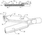
- FIG. 5is a fragmentary perspective view of the working end of a surgical grasping device of the kind shown in FIG. 1, with grasping attachments in accordance with the invention removably connected to both of its jaws; and
- FIG. 6is a sectional view, similar to FIG. 4, showing an alternative grasping attachment.
- the instrument of FIG. 1is a typical endoscopic forceps having a handle assembly 10 having a pair of ring handles 12 and 14 , handle 12 being movable toward handle 14 to actuate the forceps jaws 18 and 20 , which are situated at the opposite end of a barrel 22 from the handle.
- the direction from the handle assembly 10 toward the jawswill be referred to as the “distal” direction and the direction from the jaws toward the handle assembly will be referred to as the “proximal” direction.
- a conventional linkagelocated inside the handle and inside the barrel causes the jaws 18 and 20 to approach each other as the handle 12 is moved toward handle 14 , and to move away from each other as the handle 12 is moved away from handle 14 .
- both of the jawsmove symmetrically relative to the barrel axis
- alternative arrangementsfor example, one in which only one of the jaws moves while the other remains in fixed relationship to the barrel.
- each of the jawsis generally in the form of an elongated metal plate extending distally from a stem.
- jaw 18comprises a plate having a stem 24 extending through a slot 26 at the distal end of the barrel 22
- jaw 20similarly comprises a plate having a stem 28 extending through slot 26 .
- Each platehas inner and outer faces, the upper face 30 on jaw 18 being an outer face, and the upper face 32 on jaw 20 being an inner face.
- Each of the plateshas a central portion having parallel edges, the parallel edges of the plate of jaw 18 being seen at 34 and 36 , and the parallel edges of the plate of jaw 20 being seen at 38 and 40 .
- the inner faces of the jawsare in opposed relationship to each other, and can be brought into a relationship with each other such that the inner faces are parallel to each other and spaced from each other by a distance of about 2 mm.
- each jawis tapered adjacent to its distal end and has a tip comprising parallel edges which are closer to each other than the parallel edges of the main portion of the plate. These tips are adapted to be engaged by a C-shaped clip of an attachment which will be described below.
- jaw 18has a tip 42
- jaw 20has a tip 44 .
- the inner face of the plate of each jawis also provided with a hole near its proximal end for receiving a projection of an attachment, as will be described.
- the holesare preferably, but not necessarily, through holes, hole 46 being a through hole in jaw 18 and hole 48 being a through hole in jaw 20 .
- the grasping attachmentswhich will be described with reference to FIGS. 2-5, are intended to provide a secure, but atraumatic, grip on anatomical tissue.
- the tissue-grasping components of the attachmentsare situated on the inner faces of the jaws 18 and 20 .
- C-shaped clipswhich constitute components of the attachments fit closely onto the tips 42 and 44 , while projections on the attachments fit into holes 46 and 48 .
- the attachmentshave resilience allowing them to be bent away from the planes of the inner faces of the jaws when the C-shaped clips are attached to the tips 42 and 44 . It is this same resilience which urges the projections into the holes when the C-shaped clips are engaged with the tips, thereby securing the attachments to the jaws and preventing unintended detachment, while allowing the attachments to be removed readily by deliberate manipulation.
- the grasping attachment 50is elongated and generally rectangular in shape. It comprises an elongated sheet metal element having a plate portion 52 with a wide part 54 adjacent to a proximal end of the attachment, a narrower part 56 extending from the wide part toward the distal end, and notches 58 and 60 spaced a short distance from the distal end.
- the sheet metal elementOn the distal side of the notches adjacent to the distal end of the grasping attachment, the sheet metal element has ears which form a C-shaped clip 62 .
- the earscomprise first parts 64 and 66 , which extend respectively, from opposite longitudinal edges 68 and 70 of the plate, out of the plane in which plate portion 52 lies.
- the earshave second parts 72 and 74 , which extend toward each other from the first parts and overlie the plate portion 52 in spaced relation thereto.
- the size of the C-shaped clip 62is such that it can be closely fitted onto one or the other of projections 42 and 44 in FIG. 1 .
- the notches 58 and 60facilitate bending of the plate portion of the metal element at a location adjacent to the C-shaped clip so that the grasping element can be readily installed on, and removed from, and instrument jaw.
- the sheet metal elementis preferably composed of a stainless steel having enough resilience to enable the C-shaped clip to grip projection 42 or 44 tightly, and to enable the narrow part 56 of the sheet metal element to bend for connection and removal of the attachment.
- a layer 76(FIGS. 3 and 4) is situated adjacent the wide part 54 of Plate portion 52 of the sheet metal element.
- This layeris a substantially rigid layer, composed of a plastics material, preferably polypropylene, or another similar synthetic resin suitable for use in a surgical instrument.
- the layer 76is a part of a molded element including a projection 78 which extends outwardly from the wide part 54 plate portion 52 .
- the elementis molded so that the margins of layer 76 underlie the plate portion and the projection overlies the plate portion, and consequently, the plastics element is permanently attached to the metal plate portion.
- the projectionis slightly tapered, having sloping sidewalls 82 and 84 , as well as sloping front and rear ends 86 and 88 , respectively.
- the top of the projectionis beveled at 90 , 92 and 94 to facilitate entry of the projection into hole 46 or 48 , and the proximal and side walls are provided with deformable ribs 96 , which, as mentioned previously, both facilitate entry of the projection into the hole in the instrument jaw and ensure a tight fit so that the grasping attachment is held firmly on the jaw.
- An elastomeric pad 98is secured to the plastics layer 76 , and to the plate portion of the metal element, preferably by an adhesive (not shown).
- the face of the plate portion which is contacted by the padmay be etched for more effective adhesion.
- the padis shaped with a rim so that it forms a recess receiving the plate portion 52 . Side portions of the rim are seen in FIG. 4 at 100 and 102 , and a distal portion of the rim is seen in FIG. 3 at 104 .
- the exposed surface of the elastomeric padis covered by a membrane which imparts to it the ability to hold anatomical tissue effectively without causing trauma.
- a membranewhich imparts to it the ability to hold anatomical tissue effectively without causing trauma.
- suitable materialscan be used, for example, a high-density non-woven polyethylene available under the trademark TYVEK, polymers such as polyvinyldiene fluoride (PVDF), and spunbonded materials such as a polyester membrane material, e.g. Ahlstorm's 3283 or Reemay's 2040 product.
- PVDFpolyvinyldiene fluoride
- spunbonded materialssuch as a polyester membrane material, e.g. Ahlstorm's 3283 or Reemay's 2040 product.
- Other suitable materialsare described in U.S. Pat. No. 5,728,121, the disclosure of which is incorporated by reference.
- grasping attachment 50is attached to a jaw 18 by engaging its C-shaped clip 62 with projection 42 of the jaw, and allowing projection 78 to enter hole 46 of the jaw.
- the spring action of the metal elementholds the projection in hole 46 so that the grasping attachment is firmly secured in place on the jaw.
- An identical grasping attachment 106may be secured to jaw 20 in a similar manner, so that the elastomeric pads of the two grasping attachments are in opposed relationship to each other.
- the grasping attachmentsmay be supplied pre-sterilized in sealed packages, and readily attached to the instrument of FIG. 1 prior to surgery. After use, the attachments can be removed from the jaws by bending the attachments until the projections clear the holes 46 and 48 and sliding the attachments in the distal direction until the C-shaped clips disengage the end projections 42 and 44 on the jaws. The attachments can then be discarded.
- the inventionmakes it possible to provide extremely small, but strong and reliable grasping attachments suitable for laparoscopic surgery using cannulae having internal diameters of 5 mm or smaller.
- the projectioncan be made to fit into hole 46 or 48 by a snap fit.
- This alternativewill be described with reference to FIG. 6, in which an elastomeric pad 108 , of silicone rubber or similar material, is secured to a layer 110 of a resilient plastics element 112 and also to metal plate 114 .
- the plastics element 112has a narrow portion 116 , which extends through a hole 118 in the metal plate, and is generally similar to the structure depicted in FIGS.
- the portion of the plastics element which engages the hole 46 or 48 in the instrument jaws 18 or 20comprises two elements 120 and 122 , having a gap 124 between them and outwardly projecting flanges 126 and 128 , which engage the outer faces of the jaws to hold the grasping element firmly in place.
- the elements 120 and 122are beveled at 130 and 132 so that the force exerted in pressing the plastics element 112 into a hole 46 or 48 pushes elements 120 and 122 toward each other, allowing the flanges 126 arid 128 to pass through the hole.
- the outer faces of element 112are configured so that the element 112 is narrower at locations 134 and 136 adjacent the flanges than at locations 138 and 140 adjacent the metal plate 114 . The narrower portion of the element 112 ensure that its flanges can reliably engage the outer face of the jaw with to which it is attached with a snap fit.
- the wider portion at the base of element 112fits snugly into hole 46 or 48 in the jaw to prevent movement of the grasping pad relative to the jaw.
- the embodiment of FIG. 6does not rely upon resilience of the metal plate 114 for secure attachment of the grasping pad to the instrument jaws, and is a preferred embodiment for most applications.
- the plastics layercan be made larger, and can even be made coextensive with the elastomeric layer, in which case the elastomeric layer is attached primarily to the plastics layer.
- Additional molded projectionswhich fit into holes in the metal layer but do not extend beyond the metal layer, can be used to supplement a projection corresponding to projection 78 in securing the plastics layer to the metal layer.
Landscapes
- Health & Medical Sciences (AREA)
- Surgery (AREA)
- Life Sciences & Earth Sciences (AREA)
- Biomedical Technology (AREA)
- Nuclear Medicine, Radiotherapy & Molecular Imaging (AREA)
- Engineering & Computer Science (AREA)
- Ophthalmology & Optometry (AREA)
- Heart & Thoracic Surgery (AREA)
- Medical Informatics (AREA)
- Molecular Biology (AREA)
- Animal Behavior & Ethology (AREA)
- General Health & Medical Sciences (AREA)
- Public Health (AREA)
- Veterinary Medicine (AREA)
- Surgical Instruments (AREA)
Abstract
Description
Claims (18)
Priority Applications (1)
| Application Number | Priority Date | Filing Date | Title |
|---|---|---|---|
| US09/680,641US6406485B1 (en) | 1999-10-08 | 2000-10-06 | Surgical grasping device and components thereof |
Applications Claiming Priority (2)
| Application Number | Priority Date | Filing Date | Title |
|---|---|---|---|
| US15832499P | 1999-10-08 | 1999-10-08 | |
| US09/680,641US6406485B1 (en) | 1999-10-08 | 2000-10-06 | Surgical grasping device and components thereof |
Publications (1)
| Publication Number | Publication Date |
|---|---|
| US6406485B1true US6406485B1 (en) | 2002-06-18 |
Family
ID=26854932
Family Applications (1)
| Application Number | Title | Priority Date | Filing Date |
|---|---|---|---|
| US09/680,641Expired - LifetimeUS6406485B1 (en) | 1999-10-08 | 2000-10-06 | Surgical grasping device and components thereof |
Country Status (1)
| Country | Link |
|---|---|
| US (1) | US6406485B1 (en) |
Cited By (44)
| Publication number | Priority date | Publication date | Assignee | Title |
|---|---|---|---|---|
| US20040044363A1 (en)* | 2002-08-27 | 2004-03-04 | Fowler David N. | Apparatus and method for removing a clip |
| US20050033324A1 (en)* | 2003-07-14 | 2005-02-10 | Dexteus | Surgical tissue guard |
| US20050240219A1 (en)* | 2004-04-22 | 2005-10-27 | Henry Kahle | Peripheral vascular occlusion devices |
| US20070260278A1 (en)* | 2006-05-03 | 2007-11-08 | Raptor Ridge, Llc | Systems and methods of tissue closure |
| US20070265644A1 (en)* | 2004-09-24 | 2007-11-15 | National University Corporaton Kobe University | Gut Clamper |
| US20110190809A1 (en)* | 2009-08-11 | 2011-08-04 | Raptor Ridge, Llc | Delivery device and method for compliant tissue fasteners |
| US20130046295A1 (en)* | 2011-08-18 | 2013-02-21 | Tyco Healthcare Group Lp | Surgical Instruments With Removable Components |
| US8685056B2 (en) | 2011-08-18 | 2014-04-01 | Covidien Lp | Surgical forceps |
| US8968307B2 (en) | 2011-08-18 | 2015-03-03 | Covidien Lp | Surgical forceps |
| US8968317B2 (en) | 2011-08-18 | 2015-03-03 | Covidien Lp | Surgical forceps |
| US9499318B2 (en) | 2014-08-21 | 2016-11-22 | Cook Medical Technologies Llc | System and method for containment and organization of medical wire |
| US9664213B2 (en) | 2014-08-21 | 2017-05-30 | Cook Medical Technologies Llc | System for containment and organization of medical wire |
| US9962221B2 (en) | 2013-08-07 | 2018-05-08 | Covidien Lp | Bipolar surgical instrument |
| USD843574S1 (en) | 2017-06-08 | 2019-03-19 | Covidien Lp | Knife for open vessel sealer |
| USD854149S1 (en) | 2017-06-08 | 2019-07-16 | Covidien Lp | End effector for open vessel sealer |
| USD854684S1 (en) | 2017-06-08 | 2019-07-23 | Covidien Lp | Open vessel sealer with mechanical cutter |
| US10426543B2 (en) | 2016-01-23 | 2019-10-01 | Covidien Lp | Knife trigger for vessel sealer |
| US10485545B2 (en) | 2013-11-19 | 2019-11-26 | Datascope Corp. | Fastener applicator with interlock |
| US10568681B2 (en)* | 2016-03-16 | 2020-02-25 | Sutter Medizintechnik Gmbh | Guide assembly for forceps |
| US10631918B2 (en) | 2015-08-14 | 2020-04-28 | Covidien Lp | Energizable surgical attachment for a mechanical clamp |
| US10631887B2 (en) | 2016-08-15 | 2020-04-28 | Covidien Lp | Electrosurgical forceps for video assisted thoracoscopic surgery and other surgical procedures |
| US10653475B2 (en) | 2017-06-08 | 2020-05-19 | Covidien Lp | Knife lockout for electrosurgical forceps |
| CN111282528A (en)* | 2020-02-28 | 2020-06-16 | 苏州大学 | Micro-reactor and method based on liquid drop tweezers |
| CN111565662A (en)* | 2017-10-30 | 2020-08-21 | 爱惜康有限责任公司 | Surgical dissector configured to apply mechanical and electrical energy |
| US10751110B2 (en) | 2013-08-07 | 2020-08-25 | Covidien Lp | Bipolar surgical instrument with tissue stop |
| US10952761B2 (en)* | 2016-09-19 | 2021-03-23 | Richard Devere Thrasher, III | Double forceps |
| US10959745B2 (en) | 2016-12-20 | 2021-03-30 | Jet Med Innovations, LLC | Radiolucent grasping device |
| US10966779B2 (en) | 2013-08-07 | 2021-04-06 | Covidien Lp | Bipolar surgical instrument |
| US10973567B2 (en) | 2017-05-12 | 2021-04-13 | Covidien Lp | Electrosurgical forceps for grasping, treating, and/or dividing tissue |
| US11065049B2 (en) | 2017-11-10 | 2021-07-20 | Gyrus Acmi, Inc. | Electrosurgical device with asymmetric seal compression |
| US11076908B2 (en) | 2016-06-02 | 2021-08-03 | Gyrus Acmi, Inc. | Two-stage electrosurgical device for vessel sealing |
| US11172980B2 (en) | 2017-05-12 | 2021-11-16 | Covidien Lp | Electrosurgical forceps for grasping, treating, and/or dividing tissue |
| US11324544B2 (en) | 2018-07-25 | 2022-05-10 | Gyrus Acmi, Inc. | Medical instrument |
| US11350982B2 (en) | 2018-12-05 | 2022-06-07 | Covidien Lp | Electrosurgical forceps |
| US11376062B2 (en) | 2018-10-12 | 2022-07-05 | Covidien Lp | Electrosurgical forceps |
| US11464561B2 (en) | 2016-06-02 | 2022-10-11 | Gyrus Acmi, Inc. | Two-stage electrosurgical device for vessel sealing |
| US11471211B2 (en) | 2018-10-12 | 2022-10-18 | Covidien Lp | Electrosurgical forceps |
| US11497520B2 (en)* | 2015-08-26 | 2022-11-15 | Cilag Gmbh International | Ultrasonic surgical instrument with replaceable clamp pad |
| US11523861B2 (en) | 2019-03-22 | 2022-12-13 | Covidien Lp | Methods for manufacturing a jaw assembly for an electrosurgical forceps |
| US11628008B2 (en) | 2020-03-16 | 2023-04-18 | Covidien Lp | Forceps with linear trigger kickout mechanism |
| US11653928B2 (en) | 2018-03-28 | 2023-05-23 | Datascope Corp. | Device for atrial appendage exclusion |
| US11660109B2 (en) | 2020-09-08 | 2023-05-30 | Covidien Lp | Cutting elements for surgical instruments such as for use in robotic surgical systems |
| US12295641B2 (en) | 2020-07-01 | 2025-05-13 | Covidien Lp | Electrosurgical forceps with swivel action nerve probe |
| US12402934B2 (en) | 2019-09-15 | 2025-09-02 | Covidien Lp | Electrosurgical instrument for grasping, treating, and/or dividing tissue incorporating thermal management feature |
Citations (3)
| Publication number | Priority date | Publication date | Assignee | Title |
|---|---|---|---|---|
| US5728121A (en) | 1996-04-17 | 1998-03-17 | Teleflex Medical, Inc. | Surgical grasper devices |
| US6206896B1 (en)* | 1998-07-27 | 2001-03-27 | Thomas J. Fogarty | Surgical clamp pad with interdigitating teeth |
| US6325810B1 (en)* | 1999-06-30 | 2001-12-04 | Ethicon, Inc. | Foam buttress for stapling apparatus |
- 2000
- 2000-10-06USUS09/680,641patent/US6406485B1/ennot_activeExpired - Lifetime
Patent Citations (3)
| Publication number | Priority date | Publication date | Assignee | Title |
|---|---|---|---|---|
| US5728121A (en) | 1996-04-17 | 1998-03-17 | Teleflex Medical, Inc. | Surgical grasper devices |
| US6206896B1 (en)* | 1998-07-27 | 2001-03-27 | Thomas J. Fogarty | Surgical clamp pad with interdigitating teeth |
| US6325810B1 (en)* | 1999-06-30 | 2001-12-04 | Ethicon, Inc. | Foam buttress for stapling apparatus |
Cited By (76)
| Publication number | Priority date | Publication date | Assignee | Title |
|---|---|---|---|---|
| US7131977B2 (en) | 2002-08-27 | 2006-11-07 | Pilling Weck Incorporated | Apparatus and method for removing a clip |
| US20070021777A1 (en)* | 2002-08-27 | 2007-01-25 | Fowler David N | Apparatus and method for removing a clip |
| US20040044363A1 (en)* | 2002-08-27 | 2004-03-04 | Fowler David N. | Apparatus and method for removing a clip |
| US20050033324A1 (en)* | 2003-07-14 | 2005-02-10 | Dexteus | Surgical tissue guard |
| WO2005007005A3 (en)* | 2003-07-14 | 2005-05-26 | Dexteus | Guard for forceps to avoid accidental needle pricks |
| US20050240219A1 (en)* | 2004-04-22 | 2005-10-27 | Henry Kahle | Peripheral vascular occlusion devices |
| US9066721B2 (en)* | 2004-09-24 | 2015-06-30 | National University Corporation Kobe University | Gut clamp |
| US20070265644A1 (en)* | 2004-09-24 | 2007-11-15 | National University Corporaton Kobe University | Gut Clamper |
| US20070260278A1 (en)* | 2006-05-03 | 2007-11-08 | Raptor Ridge, Llc | Systems and methods of tissue closure |
| US7992757B2 (en) | 2006-05-03 | 2011-08-09 | Raptor Ridge Llc | Systems and methods of tissue closure |
| US11992211B2 (en) | 2006-05-03 | 2024-05-28 | Datascope Corp. | Systems and methods of tissue closure |
| US8561872B2 (en) | 2006-05-03 | 2013-10-22 | Raptor Ridge, Llc | Systems and methods of tissue closure |
| US9375218B2 (en) | 2006-05-03 | 2016-06-28 | Datascope Corp. | Systems and methods of tissue closure |
| US10595861B2 (en) | 2006-05-03 | 2020-03-24 | Datascope Corp. | Systems and methods of tissue closure |
| US11369374B2 (en) | 2006-05-03 | 2022-06-28 | Datascope Corp. | Systems and methods of tissue closure |
| US20110190809A1 (en)* | 2009-08-11 | 2011-08-04 | Raptor Ridge, Llc | Delivery device and method for compliant tissue fasteners |
| US8647350B2 (en) | 2009-08-11 | 2014-02-11 | Raptor Ridge, Llc | Delivery device and method for compliant tissue fasteners |
| US20130046295A1 (en)* | 2011-08-18 | 2013-02-21 | Tyco Healthcare Group Lp | Surgical Instruments With Removable Components |
| US9028492B2 (en)* | 2011-08-18 | 2015-05-12 | Covidien Lp | Surgical instruments with removable components |
| US8968317B2 (en) | 2011-08-18 | 2015-03-03 | Covidien Lp | Surgical forceps |
| US8968307B2 (en) | 2011-08-18 | 2015-03-03 | Covidien Lp | Surgical forceps |
| US9888958B2 (en) | 2011-08-18 | 2018-02-13 | Covidien Lp | Surgical forceps |
| US8685056B2 (en) | 2011-08-18 | 2014-04-01 | Covidien Lp | Surgical forceps |
| US9962221B2 (en) | 2013-08-07 | 2018-05-08 | Covidien Lp | Bipolar surgical instrument |
| US11826090B2 (en) | 2013-08-07 | 2023-11-28 | Covidien Lp | Bipolar surgical instrument |
| US10966779B2 (en) | 2013-08-07 | 2021-04-06 | Covidien Lp | Bipolar surgical instrument |
| US10959770B2 (en) | 2013-08-07 | 2021-03-30 | Covidien Lp | Method of assembling an electrosurgical instrument |
| US10751110B2 (en) | 2013-08-07 | 2020-08-25 | Covidien Lp | Bipolar surgical instrument with tissue stop |
| US11612428B2 (en) | 2013-08-07 | 2023-03-28 | Covidien Lp | Bipolar surgical instrument |
| US11564689B2 (en) | 2013-11-19 | 2023-01-31 | Datascope Corp. | Fastener applicator with interlock |
| US12396729B2 (en) | 2013-11-19 | 2025-08-26 | Datascope Corporation | Fastener applicator with interlock |
| US10485545B2 (en) | 2013-11-19 | 2019-11-26 | Datascope Corp. | Fastener applicator with interlock |
| US9499318B2 (en) | 2014-08-21 | 2016-11-22 | Cook Medical Technologies Llc | System and method for containment and organization of medical wire |
| US10280955B2 (en) | 2014-08-21 | 2019-05-07 | Cook Medical Technologies Llc | System for containment and organization of medical wire |
| US10646299B2 (en) | 2014-08-21 | 2020-05-12 | Cook Medical Technologies Llc | System and method for containment and organization of medical wire |
| US9664213B2 (en) | 2014-08-21 | 2017-05-30 | Cook Medical Technologies Llc | System for containment and organization of medical wire |
| US10039611B2 (en) | 2014-08-21 | 2018-08-07 | Cook Medical Technologies Llc | System and method for containment and organization of medical wire |
| US10631918B2 (en) | 2015-08-14 | 2020-04-28 | Covidien Lp | Energizable surgical attachment for a mechanical clamp |
| US11497520B2 (en)* | 2015-08-26 | 2022-11-15 | Cilag Gmbh International | Ultrasonic surgical instrument with replaceable clamp pad |
| US10426543B2 (en) | 2016-01-23 | 2019-10-01 | Covidien Lp | Knife trigger for vessel sealer |
| US10568681B2 (en)* | 2016-03-16 | 2020-02-25 | Sutter Medizintechnik Gmbh | Guide assembly for forceps |
| US12329441B2 (en) | 2016-06-02 | 2025-06-17 | Gyrus Acmi, Inc. | Two-stage electrosurgical device for vessel sealing |
| US11957404B2 (en) | 2016-06-02 | 2024-04-16 | Gyrus Acmi, Inc. | Two-stage electrosurgical device for vessel sealing |
| US11464561B2 (en) | 2016-06-02 | 2022-10-11 | Gyrus Acmi, Inc. | Two-stage electrosurgical device for vessel sealing |
| US11076908B2 (en) | 2016-06-02 | 2021-08-03 | Gyrus Acmi, Inc. | Two-stage electrosurgical device for vessel sealing |
| US11576697B2 (en) | 2016-08-15 | 2023-02-14 | Covidien Lp | Electrosurgical forceps for video assisted thoracoscopic surgery and other surgical procedures |
| US12004766B2 (en) | 2016-08-15 | 2024-06-11 | Covidien Lp | Electrosurgical forceps for video assisted thoracoscopic surgery and other surgical procedures |
| US10631887B2 (en) | 2016-08-15 | 2020-04-28 | Covidien Lp | Electrosurgical forceps for video assisted thoracoscopic surgery and other surgical procedures |
| US10952761B2 (en)* | 2016-09-19 | 2021-03-23 | Richard Devere Thrasher, III | Double forceps |
| US10959745B2 (en) | 2016-12-20 | 2021-03-30 | Jet Med Innovations, LLC | Radiolucent grasping device |
| US12011209B2 (en) | 2017-05-12 | 2024-06-18 | Covidien Lp | Electrosurgical forceps for grasping, treating, and/or dividing tissue |
| US10973567B2 (en) | 2017-05-12 | 2021-04-13 | Covidien Lp | Electrosurgical forceps for grasping, treating, and/or dividing tissue |
| US12127784B2 (en) | 2017-05-12 | 2024-10-29 | Covidien Lp | Electrosurgical forceps for grasping, treating, and/or dividing tissue |
| US11172980B2 (en) | 2017-05-12 | 2021-11-16 | Covidien Lp | Electrosurgical forceps for grasping, treating, and/or dividing tissue |
| US10653475B2 (en) | 2017-06-08 | 2020-05-19 | Covidien Lp | Knife lockout for electrosurgical forceps |
| USD843574S1 (en) | 2017-06-08 | 2019-03-19 | Covidien Lp | Knife for open vessel sealer |
| USD854149S1 (en) | 2017-06-08 | 2019-07-16 | Covidien Lp | End effector for open vessel sealer |
| US11690666B2 (en) | 2017-06-08 | 2023-07-04 | Covidien Lp | Knife lockout for electrosurgical forceps |
| USD854684S1 (en) | 2017-06-08 | 2019-07-23 | Covidien Lp | Open vessel sealer with mechanical cutter |
| CN111565662A (en)* | 2017-10-30 | 2020-08-21 | 爱惜康有限责任公司 | Surgical dissector configured to apply mechanical and electrical energy |
| CN111565662B (en)* | 2017-10-30 | 2024-01-30 | 爱惜康有限责任公司 | Surgical dissector configured to apply mechanical and electrical energy |
| US11065049B2 (en) | 2017-11-10 | 2021-07-20 | Gyrus Acmi, Inc. | Electrosurgical device with asymmetric seal compression |
| US11653928B2 (en) | 2018-03-28 | 2023-05-23 | Datascope Corp. | Device for atrial appendage exclusion |
| US11324544B2 (en) | 2018-07-25 | 2022-05-10 | Gyrus Acmi, Inc. | Medical instrument |
| US12133673B2 (en) | 2018-10-12 | 2024-11-05 | Covidien Lp | Electrosurgical forceps |
| US11376062B2 (en) | 2018-10-12 | 2022-07-05 | Covidien Lp | Electrosurgical forceps |
| US11471211B2 (en) | 2018-10-12 | 2022-10-18 | Covidien Lp | Electrosurgical forceps |
| US11350982B2 (en) | 2018-12-05 | 2022-06-07 | Covidien Lp | Electrosurgical forceps |
| US11523861B2 (en) | 2019-03-22 | 2022-12-13 | Covidien Lp | Methods for manufacturing a jaw assembly for an electrosurgical forceps |
| US12402934B2 (en) | 2019-09-15 | 2025-09-02 | Covidien Lp | Electrosurgical instrument for grasping, treating, and/or dividing tissue incorporating thermal management feature |
| CN111282528A (en)* | 2020-02-28 | 2020-06-16 | 苏州大学 | Micro-reactor and method based on liquid drop tweezers |
| US11944369B2 (en) | 2020-03-16 | 2024-04-02 | Covidien Lp | Forceps with linear trigger kickout mechanism |
| US11628008B2 (en) | 2020-03-16 | 2023-04-18 | Covidien Lp | Forceps with linear trigger kickout mechanism |
| US12408969B2 (en) | 2020-03-16 | 2025-09-09 | Covidien Lp | Forceps with linear trigger mechanism |
| US12295641B2 (en) | 2020-07-01 | 2025-05-13 | Covidien Lp | Electrosurgical forceps with swivel action nerve probe |
| US11660109B2 (en) | 2020-09-08 | 2023-05-30 | Covidien Lp | Cutting elements for surgical instruments such as for use in robotic surgical systems |
Similar Documents
| Publication | Publication Date | Title |
|---|---|---|
| US6406485B1 (en) | Surgical grasping device and components thereof | |
| JP7526749B2 (en) | Clip applier with stabilizing element | |
| US5728121A (en) | Surgical grasper devices | |
| US7182775B2 (en) | Super atraumatic grasper apparatus | |
| EP0156218B1 (en) | Improvements relating to retractors | |
| JP4837065B2 (en) | Dialysis catheter anchoring system | |
| JP4129536B2 (en) | Highly compatible catheter anchoring system | |
| CA1274741A (en) | Cohesive-adhesive atraumatic clamp | |
| EP0648470B1 (en) | Surgical instrument positioning device | |
| US3604071A (en) | One-piece plastic towel clamp | |
| US6113535A (en) | Surgical retraction apparatus | |
| US5843101A (en) | Disposable clip for temporary vessel occulsion | |
| US20120022333A1 (en) | Apparatus and system for simultaneous use of multiple instruments | |
| US20090131976A1 (en) | Fenestrated super atraumatic grasper apparatus | |
| US20050240219A1 (en) | Peripheral vascular occlusion devices | |
| JPH10509602A (en) | Atraumatic surgical clamp instrument | |
| JP2003515360A5 (en) | ||
| WO2006081416A1 (en) | Universal utility board for use with medical devices and methods of use | |
| JP3743512B2 (en) | Surgical mantle | |
| EP1217958B1 (en) | Surgical grasping device and components thereof | |
| JPH04231045A (en) | Improved connection type artificial anus device | |
| IE67338B1 (en) | Drainage Tube Retention Device | |
| CN114027977A (en) | Medical executive component clamping structure | |
| JP2008178705A (en) | Tissue retractor retention band |
Legal Events
| Date | Code | Title | Description |
|---|---|---|---|
| AS | Assignment | Owner name:PILLING WECK INCORPORATED, PENNSYLVANIA Free format text:ASSIGNMENT OF ASSIGNORS INTEREST;ASSIGNOR:MOSADDEQ HOSSAIN ET AL.;REEL/FRAME:011207/0196 Effective date:20001006 | |
| STCF | Information on status: patent grant | Free format text:PATENTED CASE | |
| AS | Assignment | Owner name:TECHNOLOGY HOLDING COMPANY II, DELAWARE Free format text:ASSIGNMENT OF ASSIGNORS INTEREST;ASSIGNOR:PILLING WECK INCOPORATED;REEL/FRAME:014515/0774 Effective date:20021217 | |
| FPAY | Fee payment | Year of fee payment:4 | |
| FPAY | Fee payment | Year of fee payment:8 | |
| FPAY | Fee payment | Year of fee payment:12 | |
| AS | Assignment | Owner name:JPMORGAN CHASE BANK, N.A., AS ADMINISTRATIVE AGENT Free format text:SECURITY INTEREST;ASSIGNOR:TECHNOLOGY HOLDING COMPANY II;REEL/FRAME:041760/0414 Effective date:20170217 | |
| AS | Assignment | Owner name:TELEFLEX MEDICAL INCORPORATED, PENNSYLVANIA Free format text:MERGER;ASSIGNOR:TECHNOLOGY HOLDING COMPANY II;REEL/FRAME:049342/0541 Effective date:20190503 | |
| AS | Assignment | Owner name:PILLING WECK INCORPORATED, PENNSYLVANIA Free format text:ASSIGNMENT OF ASSIGNORS INTEREST;ASSIGNORS:HOSSAIN, MOSADDEQ;BANIK, ROBERT;REEL/FRAME:049755/0515 Effective date:20001006 | |
| AS | Assignment | Owner name:JPMORGAN CHASE BANK, N.A., AS ADMINISTRATIVE AGENT Free format text:SECURITY INTEREST;ASSIGNOR:TELEFLEX MEDICAL INCORPORATED;REEL/FRAME:050620/0904 Effective date:20190925 Owner name:JPMORGAN CHASE BANK, N.A., AS ADMINISTRATIVE AGENT, ILLINOIS Free format text:SECURITY INTEREST;ASSIGNOR:TELEFLEX MEDICAL INCORPORATED;REEL/FRAME:050620/0904 Effective date:20190925 |