US6406453B1 - Composite ventilation tube - Google Patents
Composite ventilation tubeDownload PDFInfo
- Publication number
- US6406453B1 US6406453B1US08/427,909US42790995AUS6406453B1US 6406453 B1US6406453 B1US 6406453B1US 42790995 AUS42790995 AUS 42790995AUS 6406453 B1US6406453 B1US 6406453B1
- Authority
- US
- United States
- Prior art keywords
- tubular shaft
- hollow tubular
- ventilation tube
- cylindrical section
- shaft
- Prior art date
- Legal status (The legal status is an assumption and is not a legal conclusion. Google has not performed a legal analysis and makes no representation as to the accuracy of the status listed.)
- Expired - Lifetime
Links
- 238000009423ventilationMethods0.000titleclaimsabstractdescription73
- 239000002131composite materialSubstances0.000titledescription2
- 239000000463materialSubstances0.000claimsabstractdescription49
- 210000003484anatomyAnatomy0.000claimsabstractdescription28
- 230000004044responseEffects0.000claimsabstractdescription7
- 238000005452bendingMethods0.000claimsdescription10
- 238000010276constructionMethods0.000claimsdescription3
- 210000003454tympanic membraneAnatomy0.000abstractdescription25
- 210000000959ear middleAnatomy0.000description11
- 238000003780insertionMethods0.000description9
- 230000037431insertionEffects0.000description9
- 229920000642polymerPolymers0.000description8
- 238000001125extrusionMethods0.000description6
- 238000004519manufacturing processMethods0.000description6
- 210000000883ear externalAnatomy0.000description4
- 239000004033plasticSubstances0.000description4
- 229920003023plasticPolymers0.000description4
- 239000000853adhesiveSubstances0.000description3
- 230000001070adhesive effectEffects0.000description3
- 230000008901benefitEffects0.000description3
- 239000007769metal materialSubstances0.000description3
- 238000000034methodMethods0.000description3
- 230000004048modificationEffects0.000description3
- 238000012986modificationMethods0.000description3
- 238000000465mouldingMethods0.000description3
- 230000009467reductionEffects0.000description3
- 206010033078Otitis mediaDiseases0.000description2
- 239000004809TeflonSubstances0.000description2
- 229920006362Teflon®Polymers0.000description2
- 238000005520cutting processMethods0.000description2
- 239000012530fluidSubstances0.000description2
- 208000014674injuryDiseases0.000description2
- 239000012528membraneSubstances0.000description2
- 230000008733traumaEffects0.000description2
- 206010061218InflammationDiseases0.000description1
- 206010062545Middle ear effusionDiseases0.000description1
- 239000004743PolypropyleneSubstances0.000description1
- 238000004026adhesive bondingMethods0.000description1
- 239000000560biocompatible materialSubstances0.000description1
- 229920001400block copolymerPolymers0.000description1
- 210000005069earsAnatomy0.000description1
- 238000000605extractionMethods0.000description1
- 238000002513implantationMethods0.000description1
- 230000004054inflammatory processEffects0.000description1
- 238000009434installationMethods0.000description1
- 238000005304joiningMethods0.000description1
- 230000014759maintenance of locationEffects0.000description1
- 230000013011matingEffects0.000description1
- 239000002184metalSubstances0.000description1
- 239000002480mineral oilSubstances0.000description1
- 208000005923otitis media with effusionDiseases0.000description1
- 230000002085persistent effectEffects0.000description1
- -1polypropylenePolymers0.000description1
- 229920001155polypropylenePolymers0.000description1
- 229920001296polysiloxanePolymers0.000description1
- 229920005996polystyrene-poly(ethylene-butylene)-polystyrenePolymers0.000description1
- 229920001343polytetrafluoroethylenePolymers0.000description1
- 239000004810polytetrafluoroethyleneSubstances0.000description1
- 230000008569processEffects0.000description1
- 230000000717retained effectEffects0.000description1
- 238000005488sandblastingMethods0.000description1
- 238000000926separation methodMethods0.000description1
- 229920002545silicone oilPolymers0.000description1
- 229910001220stainless steelInorganic materials0.000description1
- 239000010935stainless steelSubstances0.000description1
- 238000001356surgical procedureMethods0.000description1
- 229920002725thermoplastic elastomerPolymers0.000description1
Images


Classifications
- A—HUMAN NECESSITIES
- A61—MEDICAL OR VETERINARY SCIENCE; HYGIENE
- A61F—FILTERS IMPLANTABLE INTO BLOOD VESSELS; PROSTHESES; DEVICES PROVIDING PATENCY TO, OR PREVENTING COLLAPSING OF, TUBULAR STRUCTURES OF THE BODY, e.g. STENTS; ORTHOPAEDIC, NURSING OR CONTRACEPTIVE DEVICES; FOMENTATION; TREATMENT OR PROTECTION OF EYES OR EARS; BANDAGES, DRESSINGS OR ABSORBENT PADS; FIRST-AID KITS
- A61F11/00—Methods or devices for treatment of the ears or hearing sense; Non-electric hearing aids; Methods or devices for enabling ear patients to achieve auditory perception through physiological senses other than hearing sense; Protective devices for the ears, carried on the body or in the hand
- A61F11/20—Ear surgery
- A61F11/202—Surgical middle-ear ventilation or drainage, e.g. permanent; Implants therefor
- A—HUMAN NECESSITIES
- A61—MEDICAL OR VETERINARY SCIENCE; HYGIENE
- A61M—DEVICES FOR INTRODUCING MEDIA INTO, OR ONTO, THE BODY; DEVICES FOR TRANSDUCING BODY MEDIA OR FOR TAKING MEDIA FROM THE BODY; DEVICES FOR PRODUCING OR ENDING SLEEP OR STUPOR
- A61M25/00—Catheters; Hollow probes
- A61M25/0009—Making of catheters or other medical or surgical tubes
Definitions
- the present inventionrelates generally to medical ventilation tubes and, more particularly, to myringotomy ventilation tubes that can be placed in the tympanic membrane of the ear to drain fluid and alleviate a buildup or reduction of pressure in the middle ear.
- tubes in the tympanic membranewhich separates the middle ear from the outer ear
- a myringotomyis performed to create an opening in the tympanic membrane and a vent or drain in the form of a tube is inserted into the opening to permit drainage of fluid from the middle ear to alleviate a buildup or reduction of pressure in the middle ear cavity.
- the tubefunctions to maintain the opening in the tympanic membrane for a sufficient period of time following the surgery to allow pressure to equalize between the middle and outer ears.
- the condition of buildup or reduction of pressure in the middle ear cavity which the tube is intended to alleviaterequires that the tube remain in place for a significant period of time ranging in duration from about six to about twenty four months.
- Ventilation tubes for insertion into an opening in the tympanic membranehave been introduced over the years.
- Prior art ventilation tubes without flanges at either endare easy to insert into the myringotomy opening but are disadvantageous in that they can be accidentally extracted from the tympanic membrane.
- ventilation tubes having flanges at one or both endsare less likely to be accidentally extracted from the tympanic membrane but are difficult to insert into and extract from the myringotomy openings, tending to enlarge the myringotomy openings such that the tendency of the tubes to fall out of the membrane increases.
- Yet another object of the present inventionis to prevent enlargement of an opening in an anatomical structure, such as the tympanic membrane, in response to insertion or removal of a medical ventilation tube through the opening.
- Still another object of the present inventionis to form a ventilation tube as a composite structure made of two or more materials of different durometer.
- the present inventionis generally characterized in a medical ventilation tube for placement in an anatomical structure including a hollow tubular shaft having a passage formed therethrough, the hollow tubular shaft being made of a first material having a rigidity to resist bending and maintain the passage in an open condition when the ventilation tube is placed in the anatomical structure, and a flange extending outwardly from the hollow tubular shaft, the flange being made of a second material having a rigidity less than that of the first material to permit the flange to deform in response to contact with the anatomical structure.
- the first materialis preferably a polymer having a durometer no greater than about 100 on the Shore A hardness scale
- the second materialis also preferably a polymer having a durometer less than that of the first material but greater than about 20 on the Shore A hardness scale.
- the first materialis a polymer having a durometer of about 90 to about 95 on the Shore A hardness scale
- a second materialis a polymer having a durometer of about 50 on the Shore A hardness scale.
- Another aspect of the present inventionis generally characterized in a method of making a medical ventilation tube including the steps of forming a hollow tubular shaft from a first material having a rigidity to resist bending and to maintain a passage through the shaft when the ventilation tube is placed in an anatomical structure, and molding a flange onto the hollow tubular shaft using a second material having a rigidity less than that of the first material to permit the flange to be deformed in response to contact with the anatomical structure.
- the ventilation tubecan be inserted into an opening in an anatomical structure, such as the tympanic membrane, without buckling or bending of the hollow shaft, that extrusion of the ventilation tube is prevented while maintaining a passage of substantially constant diameter through the opening, and that the ventilation tube can be formed using a wide range of materials having a variety of properties suitable for improving ease of insertion and removal, preventing extrusion and maintaining structural rigidity of the ventilation tube.
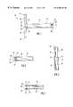
- FIG. 1is a top plan view, partly in section, showing a ventilation tube according to the present invention.
- FIG. 2is a fragmentary side view of the ventilation tube of FIG. 1 .
- FIG. 3is a front elevational view of the ventilation tube of FIG. 1 .
- FIG. 4is a fragmentary side view, in section, taken through line 4 — 4 in FIG. 1 .
- FIG. 5is an exploded perspective view of a mold used in fabricating a ventilation tube according to the present invention.
- FIGS. 6-10are fragmentary sectional side views illustrating a method of making a ventilation tube according to the present invention.
- FIG. 11is a perspective view, partly in section, illustrating use of a ventilation tube according to the present invention.
- FIG. 12is a fragmentary side view, partly in section, showing a modification of the ventilation tube according to the present invention.
- FIG. 13is a fragmentary side view, partly in section, showing another modification of the ventilation tube according to the present invention.
- the medical ventilation tube of the present inventioncan be used to maintain an opening in any anatomical structure within the body; and, accordingly, while the ventilation tube is described herein as a myringotomy ventilation tube for placement in an opening formed in the tympanic membrane of the ear, it will be appreciated that the medical ventilation tube of the present invention can be placed in other naturally occurring and surgically created openings throughout the body.
- a ventilation tube 10includes a hollow tubular body or shaft 12 and a flanged end portion 14 .
- Shaft 12is formed of a right circular cylinder 16 with a proximal end 18 , a distal end 20 and a lumen 22 extending between the proximal and distal ends to define at least part of a passage through an anatomical structure such as the tympanic membrane of the ear.
- Shaft 12is preferably made of a medically acceptable plastic or metal material having a hardness or durometer suitable for withstanding axial insertion forces without buckling or bending and for maintaining the passage in a substantially unobstructed, open condition to permit drainage and ventilation of the middle ear over extended periods of time.
- End portion 14includes a cylindrical section 24 extending from the distal end of shaft 12 to a transverse cross-member or flange 26 .
- flange 26is generally semicylindrical in cross-section with a concave side 28 facing distally and a convex side 30 facing proximally to form an abutment surface for contacting the tympanic membrane of the ear around the myringotomy opening.
- a pair of semi-circular cut-outs or notches 32 and 34are formed along distal edges 36 and 38 of the flange in opposed relation near the center of the flange to permit bending of the flange from the transverse position shown in FIG.
- Cylindrical section 24 and flange 26are preferably formed as an integral one-piece construction using a medically acceptable metal or plastic material having a hardness or durometer less than that of the shaft to facilitate bending of the flange during insertion and removal of the ventilation tube so as to minimize trauma to the tympanic membrane.
- shaft 12 and flanged end portion 14are formed of a polymeric material known as C-Flex thermoplastic elastomer.
- C-Flex thermoplastic elastomera polymeric material known as C-Flex thermoplastic elastomer.
- the basic formula of the C-Flex materialis described in U.S. Pat. Nos. 4,386,179 and 4,613,640, the disclosures of which are incorporated herein by reference.
- the base component of the C-Flex materialis a Styrene-Ethylene/Butylene-Styrene block copolymer (SEBS).
- SEBSStyrene-Ethylene/Butylene-Styrene block copolymer
- Other components, such as silicone oil, mineral oils, and polypropylenecan be added in varying ratios to obtain a desired durometer.
- “Durometer,” as used herein,refers to the hardness of a polymer measured using the Shore A, one second scale for plastics or ASTM Method 2240. From a practical standpoint, the durometer of the shaft and flanged end portion of the ventilation tube can vary within the range of about 20 to about 100, so long as a durometer differential is maintained whereby the shaft material is of higher durometer than the flange material.
- Shaft 12is preferably formed of a C-Flex polymer or similar material having a durometer of about 90 to about 95.
- End portion 14is preferably formed of a C-Flex polymer or similar material having a durometer of about 45 to about 55. Examples of other polymeric materials that can be used include Teflon, Silicone and PTFE.
- the ventilation tube 10 describedthus far resembles in size and shape a conventional ventilation tube of the type sometimes referred to as a “Goode T-Tube.” It will be appreciated, however, that the shaft and flanged end portion of the present invention can be configured in numerous other ways to resemble any type of ventilation and drain tube having a tubular shaft and a flange at one or both ends of the shaft.
- the ventilation tube of the present inventioncould resemble in size and shape Touma T-Type, Donaldson, Armstrong, Pope, Collar Button, Per-Lee or Baldwin Butterfly type ventilation tubes.
- the shaft 12 and end portion 14 of the ventilation tube 10can be fabricated using any suitable manufacturing process and can be secured to one another by thermal or adhesive bonding or by mechanical attachment.
- a preferred manner of forming the medical ventilation tube 10is by molding the flanged end portion 14 with the shaft 12 positioned in the mold such that the flanged end portion is formed simultaneously with attachment of the shaft.
- the moldhas two parts 44 and 46 .
- Mold part 44has two semicylindrical recesses 48 formed therein in the shape of flanged end part 14 ; however, any number of recesses can be formed in mold part 44 depending upon the number of medical vent tubes to be made.
- a through hole 50extends perpendicularly downward from the bottom of each recess 48 to a bottom face of the mold part to define an outer surface of shaft 12 .
- Mold part 46has two semicylindrical projections 52 formed thereon in opposed relation to recesses 48 .
- Projections 52have a length corresponding to the length of recesses 48 but are of smaller radius to be radially spaced from inside surfaces of recesses 48 when the mold parts are assembled as shown in FIG. 6 .
- the space between projections 52 and recesses 48correspond in size and shape to flange 26 with the exception of cutouts 34 and 36 which are formed by a second pair of semicylindrical projections 54 that extend transversely across the center of each projection 52 in opposed relation to a pair of similarly sized semicylindrical recesses 56 formed in mold part 44 across recesses 48 .
- each shaft 12is defined by a core pin 58 disposed within hole 50 .
- Core pin 58includes a cylindrical base 60 snugly fitted within hole 50 and a post 62 of smaller diameter than the base disposed concentrically within hole 50 between base 60 and projection 52 .
- Channels 64 a and 64 bconnect recesses 48 with a central opening 66 formed through mold part 46 to accommodate a nozzle or the like through which a polymeric material can be injected under pressure.
- mold parts 44 and 46are assembled as shown in FIG. 6 and held together by use of clamps, threaded bolts or any other conventional means to prevent separation of the mold parts when polymeric material is injected into the mold under pressure.
- the projections on mold part 46fit within the recesses in mold part 44 to define cavities having the shape of flanged end portion 14
- core pins 58fit within holes 50 to define cavities having the shape of shaft 12 .
- a first polymeric material 67 of relatively high durometersuch as a 90 to 95 durometer C-Flex material, is injected into the mold and cured in accordance with the material manufacturer's recommendations to produce a molded part of relatively high durometer resembling the medical vent tube.
- the materialis injected into the mold through opening 66 in mold part 46 and is directed by channels 64 a and 64 b into the space between projections 52 and recesses 48 to form a flanged end portion and between core pin 58 and hole 50 to form the shaft.
- mold parts 44 and 46are pulled apart and core pins 58 are punched through mold part 44 as shown in FIG. 8 to eject the molded parts.
- End portion 14 ′ of each molded partis separated from the shaft, for example by cutting across the broken line shown in FIG. 8, and the separated end portion 14 ′ is discarded.
- Shaft 12 of the molded partis retained so that it can be placed over core pin 58 and positioned within the mold as shown in FIG. 9 when flanged end portion 14 of the medical vent tubes is to be formed.
- shaft 12essentially fills the space between core pin 58 and hole 50
- a second polymeric material 69 of lower durometer than the firstsuch as a 45 to 55 durometer C-Flex material
- the flanged end portionwill thermally bond with the shaft to form the medical ventilation tube 10 as shown in FIG. 10 .
- mold parts 44 and 46are pulled apart and core pins 58 are punched through the mold part 44 as described previously to eject the medical ventilation tubes 10 from the mold.
- shaft 12 and end portion 14 of the ventilation tube 10can be fabricated using any suitable manufacturing process and can be secured to one another using any suitable means of attachment.
- shaft 12could be formed using other well known manufacturing methods, such as by extruding a continuous length of hollow tubing and cutting the hollow tubing to a predetermined length corresponding to the length of the shaft.
- shaft 12could be made of a metal material, such as stainless steel, and provided with undercuts, grooves or other structural features to facilitate mechanical attachment and retention of the molded end portion 14 .
- the ventilation tube 10can be placed in a myringotomy opening formed in the tympanic membrane of the ear as illustrated in FIG. 11, to treat persistent middle ear effusion or severe otitis media.
- the ventilation tube 10is preferably picked up by means of a conventional forceps grasping the proximal end of shaft 12 and is advanced into the auditory canal C of the outer ear toward the tympanic membrane M.
- shaft 12is formed of a rigid material having a relatively high durometer or hardness, the shaft will resist buckling or bending caused by axial insertion forces, such as those caused by contact with anatomical structures of the ear.
- the relatively soft and flexible end portion 14can be precisely positioned adjacent the myringotomy opening by manipulation of shaft 12 and, when the longitudinal axis of the ventilation tube is substantially aligned with the opening, the end portion of the ventilation tube can be inserted through the opening.
- opposed ends 40 and 42 of the flangepass completely through the opening to be disposed on the opposite, middle ear side of the tympanic membrane, the flange is released and will recover its original transverse shape to prevent accidental extraction or extrusion of the ventilation tube from the opening.
- the ventilation tubeis thus implanted in the tympanic membrane of the ear with shaft 12 placed in the myringotomy opening to maintain a passage of substantially constant diameter through the membrane to allow unobstructed drainage and ventilation of the middle ear over brief or extended periods of time.
- the ventilation tubecan be removed by simply grasping the proximal end of shaft 12 with a forceps and extracting the end portion 14 through the myringotomy opening. As end portion 14 is withdrawn proximally through the opening, the convex side of flange 26 abuts the tympanic membrane such that opposed ends 40 and 42 of the flange are pivoted or forced together in response to the force from tissue contact.
- opposed ends of the flangeare semi-cylindrical in cross-section, they cooperate to form a substantially cylindrical profile when pivoted forward thereby easing withdrawal of the ventilation tube from the tympanic membrane without enlarging the myringotomy opening.
- the shaft and flanged end portion of the ventilation tubecan be connected in various ways without compromising strength or performance.
- FIG. 12an alternate connection is shown wherein the distal end of shaft 12 includes a recess 68 and the cylindrical section of end portion 14 includes a shoulder or step 70 joining the cylindrical section with a reduced diameter portion 72 configured to fit within recess 68 .
- Shaft 12can be made of a high durometer plastic or rigid metal material and is held in place by use of an appropriate adhesive 74 applied to shoulder 70 and/or other parts of the flanged end portion.
- flanged end portion 14is preferably stiffened by mounting on a cylindrical mandrel. After adhesive 74 is applied, shaft 12 can be pushed onto the stiffened end portion and left in place until the adhesive has cured.
- FIG. 13Another modified connection, shown in FIG. 13, involves forming a step or shoulder 76 at the distal end of shaft 12 and a recess 78 at the proximal end of flanged end portion 14 .
- a reduced diameter portion 80 of shaft 12 extending from shoulder 76is configured to fit within recess 78 at the proximal end of flanged end portion 14 to serve as a mandrel stiffening the cylindrical section of the flanged end portion.
- the shaft and flanged end portioncan be held in place with heat shrink tubing 82 or the like that surrounds the end portion in the vicinity of reduced diameter portion 80 of the shaft thereby compressing the end portion against the shaft and producing a tight frictional engagement or bond.
- Tubing 82is preferably made of a biocompatible material of relatively thin wall thickness, such as a 0.001-0.002 inch thick Teflon tubing. Pull strength or, in other words, the force required to separate the shaft from the flanged end portion, can be increased by texturing the external surface of reduced diameter portion 80 , for example by forming grooves or a cross hatch pattern on the surface or by sand blasting the surface prior to assembly.
- the ventilation tube of the present inventioncan be precisely positioned within an opening formed in an anatomical structure of the body to maintain a passage through the structure over brief or extended periods of time so as to allow unobstructed drainage and ventilation through the anatomical structure.
- the ventilation tube of the present inventioncan prevent accidental extrusion and allow removal without causing significant trauma to the anatomical structure or enlargement of the opening.
- the ventilation tubecan be placed in any anatomical structure separating two regions in need of pressure equalization, such as the tympanic membrane that separates the middle and outer ears.
- the ventilation tubecan have any configuration to fit through an opening in an anatomical structure while preventing inadvertent extrusion, including configurations utilizing T-Type or round flanges and grommet configurations wherein flanges are arranged in spaced relation along the length of the tubular shaft.
- tubularis meant having a passage extending between open ends; and, while the ventilation tube of the present invention is described herein as having a tubular shaft of cylindrical configuration, it will be appreciated that tubular shafts of any cross-sectional configuration can be used, including elliptical and polygonal cross-sectional configurations.
- the tubular shaftcan be straight, curved or angled depending upon procedural use; and, when one or more flanges are to be mounted on the shaft, the flanges can be oriented at any angle relative to a longitudinal axis of the shaft.
- the material specifications and dimensions of the ventilation tubewill vary according to the intended use and, as such, it will be appreciated that the particular materials and dimensions listed herein are merely exemplary and not meant to be limiting.
Landscapes
- Health & Medical Sciences (AREA)
- Life Sciences & Earth Sciences (AREA)
- Engineering & Computer Science (AREA)
- Biomedical Technology (AREA)
- Acoustics & Sound (AREA)
- Biophysics (AREA)
- Otolaryngology (AREA)
- Psychology (AREA)
- Surgery (AREA)
- Physics & Mathematics (AREA)
- Heart & Thoracic Surgery (AREA)
- Vascular Medicine (AREA)
- Animal Behavior & Ethology (AREA)
- General Health & Medical Sciences (AREA)
- Public Health (AREA)
- Veterinary Medicine (AREA)
- Prostheses (AREA)
Abstract
Description
Claims (3)
Priority Applications (4)
| Application Number | Priority Date | Filing Date | Title |
|---|---|---|---|
| US08/427,909US6406453B1 (en) | 1995-04-26 | 1995-04-26 | Composite ventilation tube |
| US10/028,775US6939494B2 (en) | 1995-04-26 | 2001-12-28 | Method of making ventilation tube |
| US10/028,776US6692455B2 (en) | 1995-04-26 | 2001-12-28 | Composite ventilation tube |
| US10/682,253US6936023B2 (en) | 1995-04-26 | 2003-10-10 | Composite ventilation tube |
Applications Claiming Priority (1)
| Application Number | Priority Date | Filing Date | Title |
|---|---|---|---|
| US08/427,909US6406453B1 (en) | 1995-04-26 | 1995-04-26 | Composite ventilation tube |
Related Child Applications (2)
| Application Number | Title | Priority Date | Filing Date |
|---|---|---|---|
| US10/028,775DivisionUS6939494B2 (en) | 1995-04-26 | 2001-12-28 | Method of making ventilation tube |
| US10/028,776ContinuationUS6692455B2 (en) | 1995-04-26 | 2001-12-28 | Composite ventilation tube |
Publications (1)
| Publication Number | Publication Date |
|---|---|
| US6406453B1true US6406453B1 (en) | 2002-06-18 |
Family
ID=23696815
Family Applications (4)
| Application Number | Title | Priority Date | Filing Date |
|---|---|---|---|
| US08/427,909Expired - LifetimeUS6406453B1 (en) | 1995-04-26 | 1995-04-26 | Composite ventilation tube |
| US10/028,776Expired - Fee RelatedUS6692455B2 (en) | 1995-04-26 | 2001-12-28 | Composite ventilation tube |
| US10/028,775Expired - Fee RelatedUS6939494B2 (en) | 1995-04-26 | 2001-12-28 | Method of making ventilation tube |
| US10/682,253Expired - LifetimeUS6936023B2 (en) | 1995-04-26 | 2003-10-10 | Composite ventilation tube |
Family Applications After (3)
| Application Number | Title | Priority Date | Filing Date |
|---|---|---|---|
| US10/028,776Expired - Fee RelatedUS6692455B2 (en) | 1995-04-26 | 2001-12-28 | Composite ventilation tube |
| US10/028,775Expired - Fee RelatedUS6939494B2 (en) | 1995-04-26 | 2001-12-28 | Method of making ventilation tube |
| US10/682,253Expired - LifetimeUS6936023B2 (en) | 1995-04-26 | 2003-10-10 | Composite ventilation tube |
Country Status (1)
| Country | Link |
|---|---|
| US (4) | US6406453B1 (en) |
Cited By (14)
| Publication number | Priority date | Publication date | Assignee | Title |
|---|---|---|---|---|
| US6692455B2 (en)* | 1995-04-26 | 2004-02-17 | Medtronic Xomed, Inc. | Composite ventilation tube |
| US20050054996A1 (en)* | 2003-09-09 | 2005-03-10 | Gregory Christopher C. | Fecal management appliance and method and apparatus for introducing same |
| US20060122553A1 (en)* | 2002-09-11 | 2006-06-08 | Khalil Hanna | Closure cap for lachrymal canaliculus |
| US20060189951A1 (en)* | 2002-08-21 | 2006-08-24 | Kim Jae H | Bowel management system and waste collection bag therefor |
| US20080082037A1 (en)* | 2006-09-29 | 2008-04-03 | Pearson Andrew Robert | Tear-duct drain |
| US20090209972A1 (en)* | 2008-02-20 | 2009-08-20 | Loushin Michael K H | Ventilation Device and Insertion System Therefor |
| US20120029296A1 (en)* | 2010-07-29 | 2012-02-02 | KYPHON SARL. A Limited Liability Company | Expandable cannula assemblies for use in percutaneous surgical procedures |
| US8480610B1 (en)* | 1998-12-08 | 2013-07-09 | Frank C. Hill | Ear tube and method of insertion |
| US8574240B2 (en) | 2011-01-07 | 2013-11-05 | Preceptis Medical, Inc. | Stabilization system and aspiration device with protected cutting edge |
| US9370448B2 (en) | 2012-06-15 | 2016-06-21 | Preceptis Medical, Inc. | Insertion system for deploying a ventilation device |
| US9907699B2 (en) | 2012-07-05 | 2018-03-06 | Domestic Legacy Limited Partnership | One step tympanostomy tube and method of inserting same |
| USD829390S1 (en)* | 2016-12-23 | 2018-09-25 | Jurox Pty Ltd | Intravaginal device |
| US10687982B2 (en) | 2012-07-05 | 2020-06-23 | Domestic Legacy Limited Partnership | One-step tympanostomy tube and method for inserting same |
| US12390370B2 (en) | 2019-11-01 | 2025-08-19 | Aventamed Designated Activity Company | Tympanostomy tube |
Families Citing this family (39)
| Publication number | Priority date | Publication date | Assignee | Title |
|---|---|---|---|---|
| EP3103422A1 (en) | 2003-03-14 | 2016-12-14 | Intersect ENT, Inc. | Sinus delivery of sustained release therapeutics |
| US20060036313A1 (en)* | 2004-08-11 | 2006-02-16 | Vassiliades Thomas A | Apicoaortic conduit connector and method for using |
| US9138228B2 (en)* | 2004-08-11 | 2015-09-22 | Emory University | Vascular conduit device and system for implanting |
| JP5247428B2 (en)* | 2005-04-04 | 2013-07-24 | インターセクト エント, インコーポレイテッド | Apparatus and method for treating sinus symptoms |
| CA2612933C (en)* | 2005-06-20 | 2014-08-19 | Otomedics Advanced Medical Technologies Ltd. | Ear tubes |
| JP2007210083A (en)* | 2006-02-13 | 2007-08-23 | Hitachi Ltd | MEMS device and manufacturing method thereof |
| US8725518B2 (en)* | 2006-04-25 | 2014-05-13 | Nice Systems Ltd. | Automatic speech analysis |
| US8535707B2 (en)* | 2006-07-10 | 2013-09-17 | Intersect Ent, Inc. | Devices and methods for delivering active agents to the osteomeatal complex |
| US7846123B2 (en) | 2007-04-24 | 2010-12-07 | Emory University | Conduit device and system for implanting a conduit device in a tissue wall |
| US20090099573A1 (en)* | 2007-10-10 | 2009-04-16 | Donald Gonzales | Apparatus and Method for Treating Eustachian Tube Dysfunction |
| EP3791826B1 (en) | 2007-12-18 | 2025-01-29 | Intersect ENT, Inc. | Self-expanding devices |
| AU2009276505B2 (en)* | 2008-08-01 | 2015-04-23 | Intersect Ent, Inc. | Methods and devices for crimping self-expanding devices |
| US9795442B2 (en) | 2008-11-11 | 2017-10-24 | Shifamed Holdings, Llc | Ablation catheters |
| EP2754463B1 (en)* | 2009-05-15 | 2016-06-22 | Intersect ENT, Inc. | Expandable devices |
| AU2011252976A1 (en) | 2010-05-12 | 2012-11-08 | Shifamed Holdings, Llc | Low profile electrode assembly |
| US9655677B2 (en) | 2010-05-12 | 2017-05-23 | Shifamed Holdings, Llc | Ablation catheters including a balloon and electrodes |
| USD737445S1 (en)* | 2010-07-09 | 2015-08-25 | Cheiron Japan Co. | Urination control device |
| US9022967B2 (en) | 2010-10-08 | 2015-05-05 | Sinopsys Surgical, Inc. | Implant device, tool, and methods relating to treatment of paranasal sinuses |
| JP6130302B2 (en) | 2011-01-28 | 2017-05-17 | アピカ カーディオヴァスキュラー リミテッド | System for sealing tissue wall stings |
| WO2012106422A2 (en) | 2011-02-01 | 2012-08-09 | Georgia Tech Research Corporation | Systems for implanting and using a conduit within a tissue wall |
| US9011363B2 (en) | 2012-04-10 | 2015-04-21 | Acclarent, Inc. | Tympanic membrane pressure equalization tube |
| USD707822S1 (en) | 2012-04-10 | 2014-06-24 | Acclarent, Inc. | Tympanic membrane pressure equalization tube |
| WO2013154843A1 (en) | 2012-04-11 | 2013-10-17 | Sinopsys Surgical, Inc. | Implantation tools, tool assemblies, kits and methods |
| US8480611B1 (en) | 2012-10-02 | 2013-07-09 | Hasan M. Sh. Sh. Alshemari | Middle ear ventilation tube |
| EP2948104B1 (en) | 2013-01-25 | 2019-07-24 | Apica Cardiovascular Limited | Systems for percutaneous access, stabilization and closure of organs |
| DK2903575T3 (en) | 2013-01-25 | 2018-01-22 | Dcs Surgical Inc | IMPLANT DEVICE AND NUTRITIONAL ACCESS KIT |
| AU2014236729B2 (en) | 2013-03-14 | 2018-11-22 | Intersect Ent, Inc. | Systems, devices, and method for treating a sinus condition |
| EP2968717A4 (en) | 2013-03-15 | 2017-02-22 | Apk Advanced Medical Technologies, Inc. | Devices, systems, and methods for implanting and using a connnector in a tissue wall |
| US10098694B2 (en) | 2013-04-08 | 2018-10-16 | Apama Medical, Inc. | Tissue ablation and monitoring thereof |
| US10349824B2 (en) | 2013-04-08 | 2019-07-16 | Apama Medical, Inc. | Tissue mapping and visualization systems |
| KR20150140760A (en) | 2013-04-08 | 2015-12-16 | 아파마 메디칼, 인크. | Cardiac ablation catheters and methods of use thereof |
| EP3057549B1 (en) | 2013-10-16 | 2020-08-19 | Sinopsys Surgical, Inc. | Apparatuses, tools and kits relating to fluid manipulation treatments of paranasal sinuses |
| US10898375B2 (en) | 2014-07-24 | 2021-01-26 | Sinopsys Surgical, Inc. | Paranasal sinus access implant devices and related products and methods |
| US10485909B2 (en) | 2014-10-31 | 2019-11-26 | Thoratec Corporation | Apical connectors and instruments for use in a heart wall |
| JP2018504209A (en) | 2015-01-22 | 2018-02-15 | インターセクト エント, インコーポレイテッド | Drug coated balloon |
| EP4302713A3 (en) | 2015-11-16 | 2024-03-13 | Boston Scientific Scimed, Inc. | Energy delivery devices |
| ES3012747T3 (en) | 2017-09-20 | 2025-04-10 | Sinopsys Surgical Inc | Paranasal sinus fluid access implantation tools and assemblies |
| US12403291B2 (en) | 2019-08-30 | 2025-09-02 | Intersect Ent, Inc. | Submucosal bioresorbable drug eluting platform |
| CN113633839A (en)* | 2021-09-10 | 2021-11-12 | 优尔爱(常州)医疗科技有限公司 | Ventilation drainage tube |
Citations (9)
| Publication number | Priority date | Publication date | Assignee | Title |
|---|---|---|---|---|
| US3835863A (en)* | 1973-05-15 | 1974-09-17 | Mpc Kurgi Sil | T tube |
| US4613640A (en)* | 1985-11-13 | 1986-09-23 | Medical Research Associates, Ltd. #2 | Transparent thermoplastic elastomeric compositions and articles produced therefrom |
| US4695275A (en)* | 1983-12-16 | 1987-09-22 | Donald Bruce | Middle ear ventilation tube |
| US5116327A (en)* | 1989-06-05 | 1992-05-26 | Helix Medical, Inc. | Hysterectomy drain appliance |
| US5775336A (en)* | 1996-05-31 | 1998-07-07 | Georgetown University | Tubular medical device |
| US5851199A (en)* | 1997-10-14 | 1998-12-22 | Peerless; Sidney A. | Otological drain tube |
| US6010463A (en)* | 1993-10-28 | 2000-01-04 | I-Stat | Fluid sample collection and introduction device and method |
| US6027532A (en)* | 1998-01-13 | 2000-02-22 | Hobeika; Claude P. | Ear vent device and method of inserting the same |
| US6146364A (en)* | 1996-12-27 | 2000-11-14 | Kawasumi Laboratories, Inc. | Medical device having a branch and process for producing the same |
Family Cites Families (24)
| Publication number | Priority date | Publication date | Assignee | Title |
|---|---|---|---|---|
| US3788327A (en) | 1971-03-30 | 1974-01-29 | H Donowitz | Surgical implant device |
| US3948271A (en) | 1972-11-07 | 1976-04-06 | Taichiro Akiyama | Drain for the eardrum and apparatus for introducing the same |
| JPS5122405B2 (en) | 1973-10-26 | 1976-07-09 | ||
| US3871380A (en) | 1973-12-03 | 1975-03-18 | Richards Mfg Co | Myringotomy drain tube |
| US4037604A (en) | 1976-01-05 | 1977-07-26 | Newkirk John B | Artifical biological drainage device |
| US4284459A (en)* | 1978-07-03 | 1981-08-18 | The Kendall Company | Method for making a molded catheter |
| US4402681A (en) | 1980-08-23 | 1983-09-06 | Haas Joseph S | Artificial implant valve for the regulation of intraocular pressure |
| US4354495A (en)* | 1980-10-30 | 1982-10-19 | Sherwood Medical Industries Inc. | Method of connecting plastic tube to a plastic part |
| US4568337A (en) | 1984-04-17 | 1986-02-04 | Richards Medical Company | Ventilation tube permitting two-way gaseous communication with one-way liquid valve |
| US5186168A (en)* | 1984-11-21 | 1993-02-16 | Spofford Bryan T | Transtracheal catheter system and method |
| US4744792A (en) | 1985-01-22 | 1988-05-17 | Richards Medical Company | Middle ear ventilating tube |
| US4964850A (en) | 1986-05-07 | 1990-10-23 | Vincent Bouton | Method for treating trans-nasal sinus afflictions using a double t-shaped trans-nasal aerator |
| GB8620650D0 (en) | 1986-08-26 | 1986-10-01 | Royal Postgrad Med School | Implantable bone drain |
| US4886488A (en) | 1987-08-06 | 1989-12-12 | White Thomas C | Glaucoma drainage the lacrimal system and method |
| US5026378A (en) | 1989-11-09 | 1991-06-25 | Goldsmith Iii Manning M | Punch myringotomy system and method |
| US5080650A (en)* | 1991-01-28 | 1992-01-14 | Abbott Laboratories | Gastrostomy tube |
| US5246455A (en)* | 1991-05-17 | 1993-09-21 | Micromedics, Inc. | Middle meatal antrostomy ventilation tube |
| US5300020A (en) | 1991-05-31 | 1994-04-05 | Medflex Corporation | Surgically implantable device for glaucoma relief |
| JPH0538769A (en)* | 1991-07-19 | 1993-02-19 | Mitsutoyo Jushi Kk | Injection molding a thick flange on the end of a blow molded tube |
| US5178623A (en) | 1992-02-11 | 1993-01-12 | Cinberg James Z | Tympanic ventilation tube, applicator, and related technique |
| US5399164A (en) | 1992-11-02 | 1995-03-21 | Catheter Imaging Systems | Catheter having a multiple durometer |
| US5380301A (en)* | 1992-07-10 | 1995-01-10 | Sherwood Medical Company | Catheter/hub strain relief and method of manufacture thereof |
| US6406453B1 (en)* | 1995-04-26 | 2002-06-18 | Medtronic Xomed, Inc. | Composite ventilation tube |
| SE513688C2 (en)* | 1996-12-12 | 2000-10-23 | Dalloz Safety Ab | Earplug, method of manufacturing an integrated earplug and use of multi-material injection molding to provide such an earplug |
- 1995
- 1995-04-26USUS08/427,909patent/US6406453B1/ennot_activeExpired - Lifetime
- 2001
- 2001-12-28USUS10/028,776patent/US6692455B2/ennot_activeExpired - Fee Related
- 2001-12-28USUS10/028,775patent/US6939494B2/ennot_activeExpired - Fee Related
- 2003
- 2003-10-10USUS10/682,253patent/US6936023B2/ennot_activeExpired - Lifetime
Patent Citations (9)
| Publication number | Priority date | Publication date | Assignee | Title |
|---|---|---|---|---|
| US3835863A (en)* | 1973-05-15 | 1974-09-17 | Mpc Kurgi Sil | T tube |
| US4695275A (en)* | 1983-12-16 | 1987-09-22 | Donald Bruce | Middle ear ventilation tube |
| US4613640A (en)* | 1985-11-13 | 1986-09-23 | Medical Research Associates, Ltd. #2 | Transparent thermoplastic elastomeric compositions and articles produced therefrom |
| US5116327A (en)* | 1989-06-05 | 1992-05-26 | Helix Medical, Inc. | Hysterectomy drain appliance |
| US6010463A (en)* | 1993-10-28 | 2000-01-04 | I-Stat | Fluid sample collection and introduction device and method |
| US5775336A (en)* | 1996-05-31 | 1998-07-07 | Georgetown University | Tubular medical device |
| US6146364A (en)* | 1996-12-27 | 2000-11-14 | Kawasumi Laboratories, Inc. | Medical device having a branch and process for producing the same |
| US5851199A (en)* | 1997-10-14 | 1998-12-22 | Peerless; Sidney A. | Otological drain tube |
| US6027532A (en)* | 1998-01-13 | 2000-02-22 | Hobeika; Claude P. | Ear vent device and method of inserting the same |
Non-Patent Citations (1)
| Title |
|---|
| Polyurethanes, The Bridge Between Silicone Rubbers and Plastics.* |
Cited By (35)
| Publication number | Priority date | Publication date | Assignee | Title |
|---|---|---|---|---|
| US6692455B2 (en)* | 1995-04-26 | 2004-02-17 | Medtronic Xomed, Inc. | Composite ventilation tube |
| US20040077989A1 (en)* | 1995-04-26 | 2004-04-22 | Goode Richard L. | Composite ventilation tube |
| US6936023B2 (en)* | 1995-04-26 | 2005-08-30 | Medtronic Xomed, Inc. | Composite ventilation tube |
| US8480610B1 (en)* | 1998-12-08 | 2013-07-09 | Frank C. Hill | Ear tube and method of insertion |
| US8323255B2 (en) | 2002-08-21 | 2012-12-04 | Hollister Incorporated | Bowel management system |
| US8801683B2 (en) | 2002-08-21 | 2014-08-12 | Hollister Incorporated | Bowel management system |
| US20060189951A1 (en)* | 2002-08-21 | 2006-08-24 | Kim Jae H | Bowel management system and waste collection bag therefor |
| US20080262447A2 (en)* | 2002-08-21 | 2008-10-23 | Hollister Incorporated | Bowel management system and waste collection bag therefor |
| US20090030387A1 (en)* | 2002-08-21 | 2009-01-29 | Hollister Incorporated | Bowel management system and waste collection bag therefor |
| US20090030386A1 (en)* | 2002-08-21 | 2009-01-29 | Hollister Incorporated | Bowel management system and waste collection bag therefor |
| US7722583B2 (en) | 2002-08-21 | 2010-05-25 | Hollister Incorporated | Bowel management system and waste collection bag therefor |
| US7510541B2 (en)* | 2002-09-11 | 2009-03-31 | Khalil Hanna | Closure cap for lachrymal canaliculus |
| US20060122553A1 (en)* | 2002-09-11 | 2006-06-08 | Khalil Hanna | Closure cap for lachrymal canaliculus |
| US8016816B2 (en) | 2003-09-09 | 2011-09-13 | Convatec Technologies Inc. | Fecal management appliance and method and apparatus for introducing same |
| US10772755B2 (en) | 2003-09-09 | 2020-09-15 | Convatec Technologies Inc. | Fecal management appliance and method and apparatus for introducing same |
| US20050054996A1 (en)* | 2003-09-09 | 2005-03-10 | Gregory Christopher C. | Fecal management appliance and method and apparatus for introducing same |
| US8827970B2 (en) | 2003-09-09 | 2014-09-09 | Convatec Inc. | Fecal management appliance and method and apparatus for introducing same |
| US20080082037A1 (en)* | 2006-09-29 | 2008-04-03 | Pearson Andrew Robert | Tear-duct drain |
| US7758534B2 (en)* | 2006-09-29 | 2010-07-20 | Pearson Andrew Robert | Tear-duct drain |
| US20090209972A1 (en)* | 2008-02-20 | 2009-08-20 | Loushin Michael K H | Ventilation Device and Insertion System Therefor |
| US9023059B2 (en) | 2008-02-20 | 2015-05-05 | Preceptis Medical, Inc. | Ventilation device and insertion system therefor |
| US10624792B2 (en) | 2008-02-20 | 2020-04-21 | Preceptis Medical, Inc. | Ventilation device and insertion system therefor |
| US9782298B2 (en) | 2008-02-20 | 2017-10-10 | Preceptis Medical, Inc. | Ventilation device and insertion system therefor |
| US11771598B2 (en) | 2008-02-20 | 2023-10-03 | Preceptis Medical, Llc | Ventilation device and insertion system therefor |
| US20120029296A1 (en)* | 2010-07-29 | 2012-02-02 | KYPHON SARL. A Limited Liability Company | Expandable cannula assemblies for use in percutaneous surgical procedures |
| US8574240B2 (en) | 2011-01-07 | 2013-11-05 | Preceptis Medical, Inc. | Stabilization system and aspiration device with protected cutting edge |
| US8979868B2 (en) | 2011-01-07 | 2015-03-17 | Preceptis Medical, Inc. | Stabilization system and aspiration device with rapid diagnostics |
| US9370448B2 (en) | 2012-06-15 | 2016-06-21 | Preceptis Medical, Inc. | Insertion system for deploying a ventilation device |
| US10695224B2 (en) | 2012-06-15 | 2020-06-30 | Preceptis Medical, Inc. | Insertion system for deploying a ventilation device |
| US12023224B2 (en) | 2012-06-15 | 2024-07-02 | Preceptis Medical, Inc. | Insertion system for deploying a ventilation device |
| US10687982B2 (en) | 2012-07-05 | 2020-06-23 | Domestic Legacy Limited Partnership | One-step tympanostomy tube and method for inserting same |
| US9987168B2 (en) | 2012-07-05 | 2018-06-05 | Domestic Legacy Limited Partnership | One step tympanostomy tube and method for inserting same |
| US9907699B2 (en) | 2012-07-05 | 2018-03-06 | Domestic Legacy Limited Partnership | One step tympanostomy tube and method of inserting same |
| USD829390S1 (en)* | 2016-12-23 | 2018-09-25 | Jurox Pty Ltd | Intravaginal device |
| US12390370B2 (en) | 2019-11-01 | 2025-08-19 | Aventamed Designated Activity Company | Tympanostomy tube |
Also Published As
| Publication number | Publication date |
|---|---|
| US20020058898A1 (en) | 2002-05-16 |
| US6692455B2 (en) | 2004-02-17 |
| US6936023B2 (en) | 2005-08-30 |
| US6939494B2 (en) | 2005-09-06 |
| US20020058899A1 (en) | 2002-05-16 |
| US20040077989A1 (en) | 2004-04-22 |
Similar Documents
| Publication | Publication Date | Title |
|---|---|---|
| US6406453B1 (en) | Composite ventilation tube | |
| US20070119464A1 (en) | Enhanced earplug with bendable stiffener | |
| ES2752298T3 (en) | Introducing hub assembly with hub and method for attaching the hub to a hub tube | |
| US9713697B2 (en) | Catheter assembly, catheter systems including same, and method of manufacture | |
| CA1180247A (en) | Wound drain catheter | |
| US9084867B2 (en) | Injection moulding catheter | |
| US8007434B2 (en) | Variable stiffness medical device shaft | |
| EP1689336B1 (en) | Low sound attenuating hearing protection device | |
| JPH10137338A (en) | Catheter assembly and inner cannula | |
| ES2256240T3 (en) | STEN BILIAR AND MANUFACTURING PROCEDURE. | |
| US7887737B2 (en) | Injection moulding of a catheter | |
| JP3862026B2 (en) | Method for manufacturing catheter introducing sheath device | |
| JP7578690B2 (en) | Tympanostomy tube | |
| CA1266598A (en) | Method of making a grooved medical tube | |
| JPS59136216A (en) | Molding of synthetic resin cylindrical body | |
| JPS6142615Y2 (en) | ||
| EP0789598B1 (en) | Catheters and their manufacture |
Legal Events
| Date | Code | Title | Description |
|---|---|---|---|
| AS | Assignment | Owner name:TREBAY MEDICAL CORPORATION, FLORIDA Free format text:ASSIGNMENT OF ASSIGNORS INTEREST;ASSIGNORS:GOODE, RICHARD L.;BAYS, F. BARRY;REEL/FRAME:007657/0704;SIGNING DATES FROM 19950609 TO 19950616 | |
| AS | Assignment | Owner name:BANK OF BOSTON CONNECTICUT, CONNECTICUT Free format text:PATENT COLLATERAL ASSIGNMENT AND SECURITY AGREEMENT;ASSIGNOR:TREBAY MEDICAL CORPORATION;REEL/FRAME:007936/0498 Effective date:19960424 | |
| AS | Assignment | Owner name:XOMED SURGICAL PRODUCTS, INC., FLORIDA Free format text:ASSIGNMENT OF ASSIGNORS INTEREST;ASSIGNOR:TREBAY MEDICAL CORPORATION;REEL/FRAME:008171/0867 Effective date:19961004 | |
| AS | Assignment | Owner name:MEDTRONIC XOMED SURGICAL PRODUCTS, INC., FLORIDA Free format text:CHANGE OF NAME;ASSIGNOR:XOMED SURGICAL PRODUCTS, INC.;REEL/FRAME:012353/0550 Effective date:19991105 Owner name:MEDTRONIC XOMED, INC., FLORIDA Free format text:CHANGE OF NAME;ASSIGNOR:MEDTRONIC XOMED SURGICAL PRODUCTS, INC.;REEL/FRAME:012353/0589 Effective date:20001229 | |
| STCF | Information on status: patent grant | Free format text:PATENTED CASE | |
| FPAY | Fee payment | Year of fee payment:4 | |
| FPAY | Fee payment | Year of fee payment:8 | |
| FPAY | Fee payment | Year of fee payment:12 |