US6405910B1 - Removable retaining clip assembly - Google Patents
Removable retaining clip assemblyDownload PDFInfo
- Publication number
- US6405910B1 US6405910B1US09/799,649US79964901AUS6405910B1US 6405910 B1US6405910 B1US 6405910B1US 79964901 AUS79964901 AUS 79964901AUS 6405910 B1US6405910 B1US 6405910B1
- Authority
- US
- United States
- Prior art keywords
- panel
- aperture
- recess
- tongue
- tab
- Prior art date
- Legal status (The legal status is an assumption and is not a legal conclusion. Google has not performed a legal analysis and makes no representation as to the accuracy of the status listed.)
- Expired - Lifetime
Links
- 230000013011matingEffects0.000claimsabstractdescription11
- 238000000034methodMethods0.000claimsdescription21
- 239000004744fabricSubstances0.000description7
- 238000003825pressingMethods0.000description4
- 230000001413cellular effectEffects0.000description1
- 238000007373indentationMethods0.000description1
- 239000010985leatherSubstances0.000description1
- 239000003351stiffenerSubstances0.000description1
Images


Classifications
- A—HUMAN NECESSITIES
- A45—HAND OR TRAVELLING ARTICLES
- A45F—TRAVELLING OR CAMP EQUIPMENT: SACKS OR PACKS CARRIED ON THE BODY
- A45F5/00—Holders or carriers for hand articles; Holders or carriers for use while travelling or camping
- A45F5/02—Fastening articles to the garment
- A—HUMAN NECESSITIES
- A45—HAND OR TRAVELLING ARTICLES
- A45F—TRAVELLING OR CAMP EQUIPMENT: SACKS OR PACKS CARRIED ON THE BODY
- A45F5/00—Holders or carriers for hand articles; Holders or carriers for use while travelling or camping
- A45F5/1516—Holders or carriers for portable handheld communication devices, e.g. pagers or smart phones
- Y—GENERAL TAGGING OF NEW TECHNOLOGICAL DEVELOPMENTS; GENERAL TAGGING OF CROSS-SECTIONAL TECHNOLOGIES SPANNING OVER SEVERAL SECTIONS OF THE IPC; TECHNICAL SUBJECTS COVERED BY FORMER USPC CROSS-REFERENCE ART COLLECTIONS [XRACs] AND DIGESTS
- Y10—TECHNICAL SUBJECTS COVERED BY FORMER USPC
- Y10S—TECHNICAL SUBJECTS COVERED BY FORMER USPC CROSS-REFERENCE ART COLLECTIONS [XRACs] AND DIGESTS
- Y10S224/00—Package and article carriers
- Y10S224/929—Article carrier for electrical device
- Y10S224/93—Attached to animate bearer
- Y—GENERAL TAGGING OF NEW TECHNOLOGICAL DEVELOPMENTS; GENERAL TAGGING OF CROSS-SECTIONAL TECHNOLOGIES SPANNING OVER SEVERAL SECTIONS OF THE IPC; TECHNICAL SUBJECTS COVERED BY FORMER USPC CROSS-REFERENCE ART COLLECTIONS [XRACs] AND DIGESTS
- Y10—TECHNICAL SUBJECTS COVERED BY FORMER USPC
- Y10T—TECHNICAL SUBJECTS COVERED BY FORMER US CLASSIFICATION
- Y10T24/00—Buckles, buttons, clasps, etc.
- Y10T24/13—Article holder attachable to apparel or body
- Y10T24/1382—Receptacle type holder
Definitions
- This inventionrelates to the field of carrying cases, particularly those of the type used to carry small, portable electronic devices.
- a standard carrying case-or pouchgenerally includes an integral clip.
- a clipis used to attach the case to such things as a belt or over the waistline of clothes.
- Mobile handheldssuch as the RIM® 950 Wireless HandheldTM, are carried in cases having such a clip.
- the clipis used to attach the case to the user's belt or over the waistline of their clothes, as examples, to make carrying easier.
- Carrying cases with integral clipsdo not allow the user to remove the clip in order to carry the device more easily in pockets. That is, the clip can make the case bulky. Cases made bulky by clips can be problematic if the pouch or case is to be placed in a small, enclosed area such as a pocket. It may sometimes be desirable to decrease the bulk of a carrying case by removing the clip from the carrying case.
- the present inventionprovides an apparatus for use with a handheld device.
- the apparatusincludes a panel configured to provide support for the handheld device, defining an aperture and having a mating structure located in the aperture.
- the apparatusfurther includes a clip assembly operative to engage an article of clothing and configured to releasably attach to the mating structure, and thereby to impart a first configuration to the apparatus.
- the apparatusalso includes a replacement insert configured to releaseably attach to the mating structure in place of the clip assembly, and thereby to impart a second configuration to the apparatus.
- the present inventionalso provides an apparatus for use with a handheld communication device.
- the apparatusincludes a panel defining an aperture and operative to support the device.
- the apparatusfurther includes a clip assembly including a first mating structure configured to attach to the panel, and thereby to impart a first configuration to the apparatus.
- the apparatusalso includes a replacement insert including a second mating structure configured to releasably attach to the panel and replace the clip assembly, and thereby to impart a second configuration to the apparatus.
- the present inventionprovides a method for use with a handheld device of attaching a clip assembly to a panel.
- the methodincludes providing a clip assembly having a recess, and the recess having a tab.
- the methodfurther includes providing a panel defining an aperture, and having a tongue located in the aperture and having a slot configured to mate with the tab.
- the methodalso includes directing the clip assembly into the aperture so that the tongue mates with the recess and the tab mates with the slot, thereby to attach the clip assembly to the panel.
- the present inventionfurther provides a method for use with a handheld device for detaching a clip assembly from a panel having an aperture.
- the methodincludes providing a clip assembly having a recess and a panel having a tongue located in the aperture, the tongue having a slot and the recess having a tab, the clip assembly being mated to the aperture, the tongue being mated with the recess and the tab being mated with the slot, thereby to secure the clip assembly to the panel.
- the methodfurther includes directing the tongue away from recess, thereby to disengage the slot from the tab.
- the methodalso includes directing the clip assembly out of the aperture, thereby to detach the clip assembly from the panel.
- the present inventionprovides a method for use with a handheld device for attaching a replacement insert to a panel having an aperture.
- the methodincludes providing the replacement insert having a recess and a panel having a tongue located in the aperture, the tongue having a slot and the recess having a tab.
- the methodfurther includes directing the replacement insert into the aperture so that the tongue mates with the recess and the tab mates with the slot, thereby attach the replacement insert to the panel.
- the present inventionfurther provides a method for use with a handheld device for detaching a replacement insert from a panel having an aperture.
- the methodincludes providing a replacement insert having a recess, and a panel having a tongue located in the aperture, the tongue having a slot and the recess having a tab, the replacement insert being mated to the aperture, the tongue being mated with the recess and the tab being mated with the slot, thereby to secure the clip assembly to the panel.
- the methodalso includes directing the tongue away from recess, thereby to disengage the slot from the tab.
- the methodfurther includes directing the replacement insert out of the aperture, thereby to detach the replacement insert from the panel.
- the clip assembly of the present inventionis particularly useful for cases and pouches that hold, store, and carry handheld electronic devices. Examples of such devices include data and communication devices.
- FIG. 1is an exploded, orthogonal front view of an apparatus comprising a first embodiment of the invention in a first configuration
- FIG. 2is an exploded, orthogonal back view of the apparatus shown in FIG. 1 in a first configuration
- FIG. 3is an exploded,,orthogonal view of the apparatus shown in FIG. 1 in a second configuration
- FIG. 4is an exploded, orthogonal view of the apparatus shown in FIG. 1 shown in a second configuration
- FIG. 5is an orthogonal front view of the apparatus shown in FIG. 1 assembled and in a first configuration
- FIG. 6is an orthogonal back view of the assembled apparatus shown in FIG. 5;
- FIG. 7is an orthogonal front view of the apparatus shown in FIG. 1 assembled and in a second configuration
- FIG. 8is an orthogonal back view of the assembled apparatus shown in FIG. 7;
- FIG. 9is an enlarged orthogonal front view of part of the apparatus shown in FIG. 1;
- FIG. 10is an enlarged orthogonal back view the part of the apparatus shown in FIG. 9;
- FIG. 11is an enlarged orthogonal front view of part of the apparatus shown in FIG. 4;
- FIG. 12is an enlarged orthogonal back view the part of the apparatus shown in FIG. 11;
- FIG. 13is a schematic front view of an apparatus comprising a second embodiment of the invention in a first configuration
- FIG. 14is a schematic back view of the apparatus shown in FIG. 13 in a first configuration
- FIG. 15is a schematic front view of the apparatus shown in FIG. 13 in a second configuration
- FIG. 16is a schematic back view of the apparatus shown in FIG. 15 .
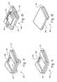
- An apparatus 100 comprising a first embodiment of the invention in a first configurationis shown in an exploded, orthogonal front view in FIG. 1 and rear view in FIG. 2 .
- the apparatus 100is shown in a second configuration in an exploded, orthogonal front view in FIG. 3 and rear view in FIG. 4 .
- the apparatus 100is a carrier case stiffener with interchangeable inserts. In the first configuration, the apparatus 100 can clip to a belt or over the waistline of clothes. In the second configuration, the apparatus 100 is less bulky so as to fit in a pocket.
- the apparatus 100includes a panel 110 made of plastic and has a top, a bottom, a front, and a back.
- the panel 110has an aperture 112 , i.e., a cutout section at the top, center of the panel 110 .
- Crimp holes 115are arranged in an array around the cutout section.
- the panelfits into the back of a pouch, not shown.
- the pouchis a carrier case for a mobile handheld electronic device, such as the RIM® 957 Wireless HandheldTM.
- the pouchis made of fabric, such as leather.
- a tongue 120having a rectangular slot 130 is located in the cutout section at the top, center of the panel 110 .
- the tongue 120is flush with the top of the panel 110 .
- the tongue 120is a resilient plastic mating structure.
- a protruding ridge 140lines the inner edge of the cutout section at the top, center of the panel 110 .
- a front crimp 150 and a back crimp 160are located on the front and back of the panel 110 , respectively.
- the front 150 and back 160 crimpsattach to the panel 110 by means of the crimp holes 115 in the panel 110 .
- the fabric of the pouchnot shown, is positioned between both the front 150 and back 160 crimp and the panel 110 .
- Alternative embodimentscan have the fabric positioned only in front of and only in back of the panel 110 .
- the apparatus 100includes a clip assembly 170 mated to the panel 110 .
- the clip assembly 170includes a base 180 .
- An orthogonal front view of just the base 180is shown in FIG. 9 and an orthogonal back view is shown in FIG. 10 .
- the base 180has a front, a back, a top, two sides, and a bottom.
- the front of the base 180has a channel shaped recess 190 , i.e., a wide shallow depression.
- the size and shape of the recess 190are such that it can mate with the tongue 120 .
- the recess 190is defined by the surfaces of the base 180 and extends fully from end to end of the base 180 .
- a tab 200is located in the recess 190 .
- the size, shape, and position of the tab 200are such that it can mate with the slot 130 when the tongue 120 is fully engaged with the recess 190 .
- the two sides of the base 180each have a recessed groove 210 that extends from the bottom to the top of the base 180 .
- the clip assembly 170also includes a clip 220 that is spring loaded and attached to the back of the base 180 .
- the manner of attachment and assembly of the clip 220 to the back of the base 180is described in patent application Ser. No. 09/305174 Retaining Clip Assembly filed May 4, 1999, now U.S. Pat. No. 6,073,318.
- a replacement insert 300is mated with the tongue 120 in the cutout section of the panel 110 .
- the replacement insert 300has parts that are substantially similar to parts of the clip assembly 170 .
- the replacement insert 300includes a base 380 .
- a front orthogonal view of the base 380is shown in FIG. 11 and a back orthogonal view is shown in FIG. 12 .
- the base 380has a front, a back, a top, two sides, and a bottom.
- the front of the base 380has a recess 390 , i.e., a narrow depression.
- the size and shape of the recess 390are such that it can mate with the tongue 120 .
- a tab 400is located in the recess 390 .
- the size and shape of the tab 400are such that it can mate with the slot 130 .
- the two sides of the base 380each have a recessed groove 410 that extends from the bottom to the top of the base 380 .
- the front 150 and back 160crimps secure the panel 110 to the fabric of the pouch using the crimp holes 165 .
- the pouch fabrichas an opening and covers the apparatus 100 except for the opening.
- the panel 110is covered in the fabric except for the front 150 and back 160 crimps. Part of either clip assembly 170 or the replacement assembly 300 may be visible through the opening depending on whether the apparatus 100 is in the first or second configuration.
- the panel 110stiffens the pouch and allows it to maintain its proper form.
- the clip assembly 170is mated with the cutout section of the panel 110 .
- the base 180slides into the cutout section of the panel 110 oriented so that the fronts of both the base 180 and the panel 110 are facing the same direction.
- the recess 190slides over the tongue 120 and each groove 210 on the side of the base 180 slides over the respective ridge 140 .
- the base 180is removably secured in place when the slot 130 slides over the tab 200 on the tongue 120 .
- the front of the panelis oriented with the pouch so that it faces toward the pouch front.
- the clip 220extends through the opening in the fabric of the pouch so that it extends downward, outside of the pouch.
- the clip assembly 170is securely attached to the panel 110 and can clip the pouch and its contents to various items.
- the pouchcan be clipped to a belt and a sun visor.
- the bulk of the clip 220may increase the total size of the carrying case. It may sometimes be desirable to reduce the size of the carrying case. For example, the first configuration may not fit into small bounded areas such as pockets as well as a carrying case having a smaller total size, i.e., less bulk.
- the clip assembly 170can be removed from the cutout section of the panel 110 by applying pressure to the tongue 120 , pulling it toward the front of the pouch, such that the slot 130 is moved from around the tab 200 . This allows the base 180 to slide out of the cutout section of the panel 110 . This allows the apparatus 100 to switch from the first configuration to the second configuration.
- the replacement insert 300is mated with the panel 110 in the cutout section rather than the clip assembly 170 being mated with the panel 110 .
- the base 380is directed into the cutout section of the panel 110 oriented so that the fronts of both the base 380 and the panel 110 are facing the same direction.
- the recess 390slides over the tongue 120 and each groove 410 slides over the respective ridge 140 .
- the base 380is removably secured in place when the slot 130 slides over the tab 400 on the tongue 120 .
- the replacement insert 300is flush with the lip of the cutout in the panel 110 .
- the replacement insert 300can be removed from the cutout section of the panel 110 by applying pressure to the tongue 120 , pulling it toward the front of the pouch, such that the slot 130 is moved from around the tab 400 . This allows the base 380 to slide out of the cutout section of the panel 110 . This allows the apparatus 100 to switch from the second configuration to the first configuration.
- FIG. 9shows a front orthogonal view of the base 180 of the clip assembly 170 .
- FIG. 10shows the back of the base 180 of the clip assembly 170 .
- This viewshows receptacles 420 for the clip 220 .
- FIG. 11shows a front orthogonal view of the base 380 of the replacement insert 300 .
- FIG. 12shows the back view, respective of FIG. 11 .
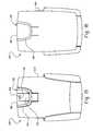
- FIG. 13An apparatus 600 comprising a second embodiment of the invention is shown in FIG. 13 .
- the apparatus 600has many parts that are substantially the same as corresponding parts of the apparatus 100 . This is indicated by the use of the same reference numbers for such corresponding parts in FIGS. 1-4 and FIGS. 13-16.
- the second embodiment of the inventiondiffers from the first embodiment in that a holster 610 replaces the pouch of the first embodiment.
- the holster 610 sides and bottomextend toward the front to form a repository for a mobile handheld device.
- the holster 610is generally open and includes curved side portions and a bottom formed to conform to the shape of the mobile handheld device.
- the apparatus 600includes two configurations.
- the apparatus 600includes the clip assembly 170 .
- the clip assembly 170is slid into the cutout section at the top of the holster 610 .
- the clip assembly 170is oriented such that both it and the holster 610 face in the same direction while the clip assembly 170 is secured in the cutout section.
- the clip assembly 170can be removed from the cutout section of the holster 610 by applying pressure to the tongue 120 , pulling it toward the front of the pouch, such that the slot 130 is moved from around the tab 200 . This allows the base 180 to slide out of the cutout section of the holster 610 . This allows the apparatus 600 to switch from the first configuration to the second configuration.
- the apparatus 600includes the replacement insert 300 .
- the replacement insert 300mated with the holster 610 in the cutout section rather than the clip assembly 170 .
- the base 380slides into the cutout section of the holster 610 and is oriented so that the fronts of both the base 380 and the holster 610 are facing the same direction.
- the recess 390slides over the tongue 120 and each groove 410 slides over the respective ridge 140 .
- the base 380is removably secured in place when the slot 130 slides over the tab 400 on the tongue 120 .
- the replacement insert 300is flush with the lip of the cutout in the holster 610 .
- the replacement insert 300can be removed from the cutout section of the holster 610 by applying pressure to the tongue 120 , pulling it toward the front of the pouch, such that the slot 130 is moved from around the tab 400 . This allows the base 380 to slide out of the cutout section of the holster 610 . This allows the apparatus 600 to switch from the second configuration to the first configuration.
- examples of the handheld deviceinclude cellular phones, digital wireless phones, 1-way pagers, 11 ⁇ 2-way pagers, 2-way pagers, electronic mail appliances, internet appliances, personal digital assistants (PDA), laptop computers, and portable digital audio players.
- PDApersonal digital assistants
Landscapes
- Telephone Set Structure (AREA)
- Casings For Electric Apparatus (AREA)
Abstract
Description
This application claims priority on U.S. Provisional Application Serial No. 60/246,179, filed on Nov. 6, 2000.
This invention relates to the field of carrying cases, particularly those of the type used to carry small, portable electronic devices.
A standard carrying case-or pouch generally includes an integral clip. Such a clip is used to attach the case to such things as a belt or over the waistline of clothes. Mobile handhelds, such as the RIM® 950 Wireless Handheld™, are carried in cases having such a clip. The clip is used to attach the case to the user's belt or over the waistline of their clothes, as examples, to make carrying easier.
Carrying cases with integral clips do not allow the user to remove the clip in order to carry the device more easily in pockets. That is, the clip can make the case bulky. Cases made bulky by clips can be problematic if the pouch or case is to be placed in a small, enclosed area such as a pocket. It may sometimes be desirable to decrease the bulk of a carrying case by removing the clip from the carrying case.
The present invention provides an apparatus for use with a handheld device. The apparatus includes a panel configured to provide support for the handheld device, defining an aperture and having a mating structure located in the aperture. The apparatus further includes a clip assembly operative to engage an article of clothing and configured to releasably attach to the mating structure, and thereby to impart a first configuration to the apparatus. The apparatus also includes a replacement insert configured to releaseably attach to the mating structure in place of the clip assembly, and thereby to impart a second configuration to the apparatus.
The present invention also provides an apparatus for use with a handheld communication device. The apparatus includes a panel defining an aperture and operative to support the device. The apparatus further includes a clip assembly including a first mating structure configured to attach to the panel, and thereby to impart a first configuration to the apparatus. The apparatus also includes a replacement insert including a second mating structure configured to releasably attach to the panel and replace the clip assembly, and thereby to impart a second configuration to the apparatus.
The present invention provides a method for use with a handheld device of attaching a clip assembly to a panel. The method includes providing a clip assembly having a recess, and the recess having a tab. The method further includes providing a panel defining an aperture, and having a tongue located in the aperture and having a slot configured to mate with the tab. The method also includes directing the clip assembly into the aperture so that the tongue mates with the recess and the tab mates with the slot, thereby to attach the clip assembly to the panel.
The present invention further provides a method for use with a handheld device for detaching a clip assembly from a panel having an aperture. The method includes providing a clip assembly having a recess and a panel having a tongue located in the aperture, the tongue having a slot and the recess having a tab, the clip assembly being mated to the aperture, the tongue being mated with the recess and the tab being mated with the slot, thereby to secure the clip assembly to the panel. The method further includes directing the tongue away from recess, thereby to disengage the slot from the tab. The method also includes directing the clip assembly out of the aperture, thereby to detach the clip assembly from the panel.
The present invention provides a method for use with a handheld device for attaching a replacement insert to a panel having an aperture. The method includes providing the replacement insert having a recess and a panel having a tongue located in the aperture, the tongue having a slot and the recess having a tab. The method further includes directing the replacement insert into the aperture so that the tongue mates with the recess and the tab mates with the slot, thereby attach the replacement insert to the panel.
The present invention further provides a method for use with a handheld device for detaching a replacement insert from a panel having an aperture. The method includes providing a replacement insert having a recess, and a panel having a tongue located in the aperture, the tongue having a slot and the recess having a tab, the replacement insert being mated to the aperture, the tongue being mated with the recess and the tab being mated with the slot, thereby to secure the clip assembly to the panel. The method also includes directing the tongue away from recess, thereby to disengage the slot from the tab. The method further includes directing the replacement insert out of the aperture, thereby to detach the replacement insert from the panel.
The clip assembly of the present invention is particularly useful for cases and pouches that hold, store, and carry handheld electronic devices. Examples of such devices include data and communication devices.
FIG. 1 is an exploded, orthogonal front view of an apparatus comprising a first embodiment of the invention in a first configuration;
FIG. 2 is an exploded, orthogonal back view of the apparatus shown in FIG. 1 in a first configuration;
FIG. 3 is an exploded,,orthogonal view of the apparatus shown in FIG. 1 in a second configuration;
FIG. 4 is an exploded, orthogonal view of the apparatus shown in FIG. 1 shown in a second configuration;
FIG. 5 is an orthogonal front view of the apparatus shown in FIG. 1 assembled and in a first configuration;
FIG. 6 is an orthogonal back view of the assembled apparatus shown in FIG. 5;
FIG. 7 is an orthogonal front view of the apparatus shown in FIG. 1 assembled and in a second configuration;
FIG. 8 is an orthogonal back view of the assembled apparatus shown in FIG. 7;
FIG. 9 is an enlarged orthogonal front view of part of the apparatus shown in FIG. 1;
FIG. 10 is an enlarged orthogonal back view the part of the apparatus shown in FIG. 9;
FIG. 11 is an enlarged orthogonal front view of part of the apparatus shown in FIG. 4;
FIG. 12 is an enlarged orthogonal back view the part of the apparatus shown in FIG. 11;
FIG. 13 is a schematic front view of an apparatus comprising a second embodiment of the invention in a first configuration;
FIG. 14 is a schematic back view of the apparatus shown in FIG. 13 in a first configuration;
FIG. 15 is a schematic front view of the apparatus shown in FIG. 13 in a second configuration;
FIG. 16 is a schematic back view of the apparatus shown in FIG.15.
Anapparatus 100 comprising a first embodiment of the invention in a first configuration is shown in an exploded, orthogonal front view in FIG.1 and rear view in FIG.2. Theapparatus 100 is shown in a second configuration in an exploded, orthogonal front view in FIG.3 and rear view in FIG.4. Theapparatus 100 is a carrier case stiffener with interchangeable inserts. In the first configuration, theapparatus 100 can clip to a belt or over the waistline of clothes. In the second configuration, theapparatus 100 is less bulky so as to fit in a pocket.
Theapparatus 100 includes apanel 110 made of plastic and has a top, a bottom, a front, and a back. Thepanel 110 has anaperture 112, i.e., a cutout section at the top, center of thepanel 110.Crimp holes 115 are arranged in an array around the cutout section. The panel fits into the back of a pouch, not shown. The pouch is a carrier case for a mobile handheld electronic device, such as the RIM® 957 Wireless Handheld™. In this embodiment, the pouch is made of fabric, such as leather.
Atongue 120, having arectangular slot 130 is located in the cutout section at the top, center of thepanel 110. Thetongue 120 is flush with the top of thepanel 110. Thetongue 120 is a resilient plastic mating structure. A protrudingridge 140 lines the inner edge of the cutout section at the top, center of thepanel 110. Afront crimp 150 and aback crimp 160 are located on the front and back of thepanel 110, respectively. The front150 and back160 crimps attach to thepanel 110 by means of the crimp holes115 in thepanel 110. The fabric of the pouch, not shown, is positioned between both the front150 and back160 crimp and thepanel 110. Alternative embodiments can have the fabric positioned only in front of and only in back of thepanel 110.
In the first configuration of this embodiment, theapparatus 100 includes aclip assembly 170 mated to thepanel 110. Theclip assembly 170 includes abase 180. An orthogonal front view of just the base180 is shown in FIG.9 and an orthogonal back view is shown in FIG.10. Thebase 180 has a front, a back, a top, two sides, and a bottom. Returning to FIGS. 1 through 4, the front of thebase 180 has a channel shapedrecess 190, i.e., a wide shallow depression. The size and shape of therecess 190 are such that it can mate with thetongue 120. Therecess 190 is defined by the surfaces of thebase 180 and extends fully from end to end of thebase 180. Atab 200 is located in therecess 190. The size, shape, and position of thetab 200 are such that it can mate with theslot 130 when thetongue 120 is fully engaged with therecess 190. The two sides of the base180 each have a recessedgroove 210 that extends from the bottom to the top of thebase 180.
Theclip assembly 170 also includes aclip 220 that is spring loaded and attached to the back of thebase 180. The manner of attachment and assembly of theclip 220 to the back of thebase 180 is described in patent application Ser. No. 09/305174 Retaining Clip Assembly filed May 4, 1999, now U.S. Pat. No. 6,073,318.
In the second configuration of this embodiment, areplacement insert 300 is mated with thetongue 120 in the cutout section of thepanel 110. Thereplacement insert 300 has parts that are substantially similar to parts of theclip assembly 170. Thereplacement insert 300 includes abase 380. A front orthogonal view of thebase 380 is shown in FIG. 11 and a back orthogonal view is shown in FIG.12. Thebase 380 has a front, a back, a top, two sides, and a bottom. Returning to the FIGS. 1 through 4, the front of thebase 380 has arecess 390, i.e., a narrow depression. The size and shape of therecess 390 are such that it can mate with thetongue 120. Atab 400 is located in therecess 390. The size and shape of thetab 400 are such that it can mate with theslot 130. The two sides of the base380 each have a recessedgroove 410 that extends from the bottom to the top of thebase 380.
When theapparatus 100 is secured in the pouch, the front150 and back160 crimps secure thepanel 110 to the fabric of the pouch using the crimp holes165. The pouch fabric has an opening and covers theapparatus 100 except for the opening. Thepanel 110 is covered in the fabric except for the front150 and back160 crimps. Part of eitherclip assembly 170 or thereplacement assembly 300 may be visible through the opening depending on whether theapparatus 100 is in the first or second configuration. Thepanel 110 stiffens the pouch and allows it to maintain its proper form.
In the first configuration, shown in FIGS. 5 and 6, theclip assembly 170 is mated with the cutout section of thepanel 110. Specifically, the base180 slides into the cutout section of thepanel 110 oriented so that the fronts of both thebase 180 and thepanel 110 are facing the same direction. Therecess 190 slides over thetongue 120 and eachgroove 210 on the side of the base180 slides over therespective ridge 140. Thebase 180 is removably secured in place when theslot 130 slides over thetab 200 on thetongue 120.
While in the first configuration the front of the panel is oriented with the pouch so that it faces toward the pouch front. Theclip 220 extends through the opening in the fabric of the pouch so that it extends downward, outside of the pouch. In this manner, theclip assembly 170 is securely attached to thepanel 110 and can clip the pouch and its contents to various items. As examples, the pouch can be clipped to a belt and a sun visor.
The bulk of theclip 220 may increase the total size of the carrying case. It may sometimes be desirable to reduce the size of the carrying case. For example, the first configuration may not fit into small bounded areas such as pockets as well as a carrying case having a smaller total size, i.e., less bulk.
Theclip assembly 170 can be removed from the cutout section of thepanel 110 by applying pressure to thetongue 120, pulling it toward the front of the pouch, such that theslot 130 is moved from around thetab 200. This allows the base180 to slide out of the cutout section of thepanel 110. This allows theapparatus 100 to switch from the first configuration to the second configuration.
In the second configuration, shown in FIGS. 7 and 8, thereplacement insert 300 is mated with thepanel 110 in the cutout section rather than theclip assembly 170 being mated with thepanel 110. Specifically, thebase 380 is directed into the cutout section of thepanel 110 oriented so that the fronts of both thebase 380 and thepanel 110 are facing the same direction. Therecess 390 slides over thetongue 120 and eachgroove 410 slides over therespective ridge 140. Thebase 380 is removably secured in place when theslot 130 slides over thetab 400 on thetongue 120. Thereplacement insert 300 is flush with the lip of the cutout in thepanel 110.
Thereplacement insert 300 can be removed from the cutout section of thepanel 110 by applying pressure to thetongue 120, pulling it toward the front of the pouch, such that theslot 130 is moved from around thetab 400. This allows the base380 to slide out of the cutout section of thepanel 110. This allows theapparatus 100 to switch from the second configuration to the first configuration.
FIG. 9 shows a front orthogonal view of thebase 180 of theclip assembly 170. FIG. 10 shows the back of thebase 180 of theclip assembly 170. This view showsreceptacles 420 for theclip 220. There is also anindentation 430 to accommodate a C-shaped leaf spring, not shown. FIG. 11 shows a front orthogonal view of thebase 380 of thereplacement insert 300. FIG. 12 shows the back view, respective of FIG.11.
Anapparatus 600 comprising a second embodiment of the invention is shown in FIG.13. Theapparatus 600 has many parts that are substantially the same as corresponding parts of theapparatus 100. This is indicated by the use of the same reference numbers for such corresponding parts in FIGS. 1-4 and FIGS. 13-16. However, the second embodiment of the invention differs from the first embodiment in that aholster 610 replaces the pouch of the first embodiment.
Theholster 610 sides and bottom extend toward the front to form a repository for a mobile handheld device. Specifically, theholster 610 is generally open and includes curved side portions and a bottom formed to conform to the shape of the mobile handheld device.
Similar to theapparatus 100, theapparatus 600 includes two configurations. In the first configuration, theapparatus 600 includes theclip assembly 170. Theclip assembly 170 is slid into the cutout section at the top of theholster 610. Theclip assembly 170 is oriented such that both it and theholster 610 face in the same direction while theclip assembly 170 is secured in the cutout section.
Theclip assembly 170 can be removed from the cutout section of theholster 610 by applying pressure to thetongue 120, pulling it toward the front of the pouch, such that theslot 130 is moved from around thetab 200. This allows the base180 to slide out of the cutout section of theholster 610. This allows theapparatus 600 to switch from the first configuration to the second configuration.
In the second configuration, theapparatus 600 includes thereplacement insert 300. Thereplacement insert 300 mated with theholster 610 in the cutout section rather than theclip assembly 170. Specifically, the base380 slides into the cutout section of theholster 610 and is oriented so that the fronts of both thebase 380 and theholster 610 are facing the same direction. Therecess 390 slides over thetongue 120 and eachgroove 410 slides over therespective ridge 140. Thebase 380 is removably secured in place when theslot 130 slides over thetab 400 on thetongue 120. Thereplacement insert 300 is flush with the lip of the cutout in theholster 610.
Thereplacement insert 300 can be removed from the cutout section of theholster 610 by applying pressure to thetongue 120, pulling it toward the front of the pouch, such that theslot 130 is moved from around thetab 400. This allows the base380 to slide out of the cutout section of theholster 610. This allows theapparatus 600 to switch from the second configuration to the first configuration.
In other embodiments of the present invention, examples of the handheld device include cellular phones, digital wireless phones, 1-way pagers, 1½-way pagers, 2-way pagers, electronic mail appliances, internet appliances, personal digital assistants (PDA), laptop computers, and portable digital audio players.
It will be appreciated that the above description relates to the preferred embodiments by way of example only. Many variations on the invention will be obvious to those knowledgeable in the field, and such variations are within the scope of the invention as described and claimed.
Claims (15)
1. A method for use with a handheld device of attaching a clip assembly to a panel comprising:
a) providing a clip assembly having a recess, and the recess having a tab;
b) providing a panel defining an aperture, and having a tongue located in the aperture and having a slot configured to mate with the tab; and
c) directing the clip assembly into the aperture so that the tongue mates with the recess and the tab mates with the slot, thereby to attach the clip assembly to the panel.
2. A method as defined inclaim 1 further comprising providing a ridge inside the aperture and side grooves on the clip assembly and directing the ridge into the side grooves simultaneously.
3. A method for use with a handheld device for detaching a clip assembly from a panel having an aperture, comprising:
a) providing a clip assembly having a recess and a panel having an aperture with a tongue located in the aperture, the tongue having a slot and the recess having a tab, the clip assembly being mated to the aperture, the tongue being mated with the recess and the tab being mated with the slot, thereby to secure the clip assembly to the panel;
b) directing the tongue away from the recess, thereby to disengage the slot from the tab; and
c) directing the clip assembly out of the aperture, thereby to detach the clip assembly from the panel.
4. A method for use with a handheld device for attaching a replacement insert to a panel having an aperture, comprising:
a) providing a replacement insert having a recess and a panel having an aperture with a tongue located in the aperture, the tongue having a slot and the recess having a tab; and
b) directing the replacement insert into the aperture so that the tongue mates with the recess and the tab mates with the slot, thereby attaching the replacement insert to the panel.
5. A method as defined inclaim 4 further comprising providing a ridge inside the aperture and side grooves on the replacement insert and directing the ridge into the side grooves simultaneously.
6. A method for use with a handheld device for detaching a replacement insert from a panel having an aperture, comprising:
a) providing a replacement insert having a recess, and a panel having an aperture with a tongue located in the aperture, the tongue having a slot and the recess having a tab, the replacement insert being mated to the aperture, the tongue being mated with the recess and the tab being mated with the slot, thereby to secure the replacement insert to the panel;
b) directing the tongue away from the recess, thereby to disengage the slot from the tab; and
c) directing the replacement insert out of the aperture, thereby to detach the replacement insert from the panel.
7. A support assembly for a handheld device comprising:
a clip assembly comprising a base portion having a recess defined therein, with a tab positioned in the recess; and
a panel having an aperture with a tongue positioned in the aperture, the tongue having a slot for mating with the tab,
wherein the clip assembly is coupled to the panel by positioning the tongue in the recess such that the tab mates with the slot.
8. The support assembly ofclaim 7 , wherein the tongue is rectangular and the slot in the tongue is rectangular, and the tab extends outwardly from a surface of the recess and is rectangular.
9. The support assembly ofclaim 7 , further comprising a clip coupled to the base portion of the clip assembly.
10. The support assembly ofclaim 7 , wherein the clip is elongated and is coupled to the base portion by a spring.
11. The support assembly ofclaim 9 , wherein the clip is coupled to the rear side of the base portion opposite the recess side.
12. The support assembly ofclaim 9 , wherein the base portion includes two protrusions on the rear side of the base portion, said protrusions including openings, and said clip includes two posts for mating with the openings in the protrusions to attach the clip to the base portion.
13. The support assembly ofclaim 7 , wherein the panel comprises a narrowed portion around the periphery of the aperture and the clip assembly base portion includes a groove position around at least a portion of the outer periphery thereof, said groove configured to mate with the narrowed portion of the panel to seat the clip assembly base portion on the panel.
14. The support assembly ofclaim 7 , further comprising a pair of crimps, each of which is mounted to one side of the panel around the edge of the aperture, said crimps having a shape that substantially conforms to the shape of the aperture.
15. The support assembly ofclaim 14 , wherein the crimps are mounted to the panel over the base portion of the clip assembly.
Priority Applications (2)
| Application Number | Priority Date | Filing Date | Title |
|---|---|---|---|
| US09/799,649US6405910B1 (en) | 2000-11-06 | 2001-03-06 | Removable retaining clip assembly |
| CA002363237ACA2363237C (en) | 2000-11-06 | 2001-10-30 | Removable retaining clip assembly |
Applications Claiming Priority (2)
| Application Number | Priority Date | Filing Date | Title |
|---|---|---|---|
| US24617900P | 2000-11-06 | 2000-11-06 | |
| US09/799,649US6405910B1 (en) | 2000-11-06 | 2001-03-06 | Removable retaining clip assembly |
Publications (1)
| Publication Number | Publication Date |
|---|---|
| US6405910B1true US6405910B1 (en) | 2002-06-18 |
Family
ID=26937773
Family Applications (1)
| Application Number | Title | Priority Date | Filing Date |
|---|---|---|---|
| US09/799,649Expired - LifetimeUS6405910B1 (en) | 2000-11-06 | 2001-03-06 | Removable retaining clip assembly |
Country Status (2)
| Country | Link |
|---|---|
| US (1) | US6405910B1 (en) |
| CA (1) | CA2363237C (en) |
Cited By (33)
| Publication number | Priority date | Publication date | Assignee | Title |
|---|---|---|---|---|
| US20030192790A1 (en)* | 2002-04-10 | 2003-10-16 | Isaacs Linda R.F. | Memo pad holder |
| US20040134945A1 (en)* | 2002-11-06 | 2004-07-15 | Robert Kincaid | Throat height adjustment in a belt loop or belt clip |
| WO2004033309A3 (en)* | 1994-11-21 | 2004-09-23 | Todd Condiff | Communication device holder |
| US20040249631A1 (en)* | 2003-03-28 | 2004-12-09 | Theresa Harris | Methods and systems for credit card-size electronic dictionary configurable as a bookmark |
| US20050006551A1 (en)* | 2003-07-10 | 2005-01-13 | Shamoon Ellis N | Clipboard |
| US6867763B2 (en) | 1998-06-26 | 2005-03-15 | Research In Motion Limited | Hand-held electronic device with a keyboard optimized for use with the thumbs |
| US20050265567A1 (en)* | 2004-06-01 | 2005-12-01 | Cortez Corley | Speaker clearance arrangement for a communication device |
| EP1610586A1 (en)* | 2004-06-01 | 2005-12-28 | Research In Motion Limited | Speaker clearance arrangement for a communication device |
| US20060101696A1 (en)* | 2004-11-03 | 2006-05-18 | Ligard Thor H | Gun barrel lock |
| US20060175370A1 (en)* | 2005-01-03 | 2006-08-10 | Michel Arney | Removable mounting post assembly for a carrying case |
| US20060237494A1 (en)* | 2005-04-25 | 2006-10-26 | Brandon Fichera | Detachable belt clip interface mechanism for phone holsters and wireless phone holster assembly |
| US20060273963A1 (en)* | 2005-06-03 | 2006-12-07 | Chen Franklin F | Antenna ring for electronic device |
| US20070225031A1 (en)* | 2005-01-03 | 2007-09-27 | Fellowes, Inc. | Portable device case with corner protector |
| US20080190976A1 (en)* | 2007-02-12 | 2008-08-14 | Chen Franklin Fk | Bridged arc antenna for an electronic device and electronic device incorporating the same |
| US20080191892A1 (en)* | 2007-02-13 | 2008-08-14 | Research In Motion Limited | System and method for providing improved detection of user inaction |
| US7445246B1 (en) | 2007-11-27 | 2008-11-04 | Gary Plastic Packaging Corp. | Clipboard assembly |
| US20090090833A1 (en)* | 2007-10-05 | 2009-04-09 | Daraz Bernard B | Mobile communication mounting device and system |
| GB2450964B (en)* | 2007-07-11 | 2010-09-29 | Wonderland Nursery Goods | A coupling device for a stroller |
| US20100288804A1 (en)* | 2009-05-12 | 2010-11-18 | Kasra Youssefi-Shams | Apparatus for supporting handheld electronic device |
| US20110004079A1 (en)* | 2006-11-29 | 2011-01-06 | Masimo Laboratories, Inc. | Optical sensor including disposable and reusable elements |
| US20130023743A1 (en)* | 2005-11-29 | 2013-01-24 | Ammar Al-Ali | Optical sensor including disposable and reusable elements |
| USD682418S1 (en) | 2012-02-15 | 2013-05-14 | 3M Innovative Properties Company | Respirator belt having attachment slot |
| USD683013S1 (en) | 2012-02-15 | 2013-05-21 | 3M Innovative Properties Company | Respirator belt having flexible air channels |
| USD683845S1 (en) | 2012-02-15 | 2013-06-04 | 3M Innovative Properties Company | Respirator belt |
| US8479960B2 (en) | 2011-05-03 | 2013-07-09 | Ruben Lopez-Apodaca | Portable telephone holder for sun visor |
| US20130306693A1 (en)* | 2012-05-16 | 2013-11-21 | Matthew C. Prestwich | Holster Clip for a Concealed Item |
| USD703806S1 (en) | 2012-02-15 | 2014-04-29 | 3M Innovative Properties Company | Respirator belt having bumper cushion |
| US9119975B2 (en) | 2012-02-15 | 2015-09-01 | 3M Innovative Properties Company | Respirator waist belt |
| US9134759B2 (en) | 1998-06-26 | 2015-09-15 | Blackberry Limited | Dual-mode mobile communication device |
| US20170122701A1 (en)* | 2015-10-30 | 2017-05-04 | Motorola Solutions, Inc. | Systems and methods for coupling a holster to another component |
| US9703390B2 (en) | 1998-06-26 | 2017-07-11 | Blackberry Limited | Hand-held electronic device |
| US10406387B2 (en) | 2012-02-15 | 2019-09-10 | 3M Innovative Properties Company | Interlock system for a respirator waist belt |
| US10820683B1 (en)* | 2019-07-30 | 2020-11-03 | Motorola Solutions, Inc. | Holster with attachment interface |
Citations (23)
| Publication number | Priority date | Publication date | Assignee | Title |
|---|---|---|---|---|
| US4083481A (en)* | 1977-03-10 | 1978-04-11 | Motorola, Inc. | Detachable mounting clip arrangement for miniature portable apparatus or the like |
| US4299344A (en)* | 1979-06-28 | 1981-11-10 | Nippon Electric Co., Ltd. | Mount for portable radio communication unit |
| US4881150A (en)* | 1987-07-10 | 1989-11-14 | Nec Corporation | Housing and holder assembly for a portable communication apparatus |
| US5081709A (en)* | 1989-08-04 | 1992-01-14 | Motorola, Inc. | Interchangeable belt clip for a selective call receiver housing and carrying case |
| US5241592A (en)* | 1991-07-31 | 1993-08-31 | Motorola, Inc. | Telephonic handset housing assembly for cordless telephone |
| US5261122A (en)* | 1990-06-11 | 1993-11-09 | Matsushita Electric Industrial Co., Ltd. | Portable electronic equipment with selectively removable exchange panel and clip |
| US5261583A (en)* | 1992-05-08 | 1993-11-16 | Motorola, Inc. | User adjustable retention latch for pager holster |
| US5297318A (en)* | 1992-08-31 | 1994-03-29 | Adolphson Bradley K | Attachable utility devices |
| US5375749A (en)* | 1991-08-30 | 1994-12-27 | Oliva; Ronald | Multi-purpose holster apparatus |
| US5385282A (en)* | 1994-02-28 | 1995-01-31 | Chen; Pao-Chin | Beeper holder |
| US5475752A (en)* | 1995-02-03 | 1995-12-12 | Motorola, Inc. | Portable telephone and support mechanism therefor |
| US5620120A (en)* | 1995-05-31 | 1997-04-15 | Tien; Tse-Hsiung | Fixing apparatus for a portable telephone |
| US5661798A (en)* | 1996-03-13 | 1997-08-26 | E. Lead Electronic Co., Ltd. | Back clip structure of a mobile phone |
| US5829102A (en)* | 1997-10-20 | 1998-11-03 | Motorola, Inc. | Housing assembly with a detachable mounting clip and a selective call receiver therein |
| US5988577A (en)* | 1997-12-31 | 1999-11-23 | Motorola, Inc. | Adjustable carrier assembly for a wireless communication device |
| US6029871A (en)* | 1997-07-04 | 2000-02-29 | Samsung Electronic Co., Ltd. | Cradle device having rotating hinge in pager |
| US6082600A (en)* | 1997-03-08 | 2000-07-04 | Angus; June | Clipable article container |
| US6141417A (en)* | 1998-08-19 | 2000-10-31 | Nokia Mobile Phones Limited | Holder for mobile telephone |
| US6161741A (en)* | 1999-06-14 | 2000-12-19 | Michaels Of Oregon Co. | Holster securement system |
| US6282802B1 (en)* | 1998-07-27 | 2001-09-04 | The Brunton Company | Hand-held needleless compass |
| US6286736B1 (en)* | 1997-03-08 | 2001-09-11 | June Angus | Clipable article container |
| US6298857B1 (en)* | 1996-11-05 | 2001-10-09 | Pacific Handy Cutter, Inc. | Hand held portable cigar humidor |
| US6311881B1 (en)* | 1998-07-07 | 2001-11-06 | Nec Corporation | Holder for a portable apparatus |
- 2001
- 2001-03-06USUS09/799,649patent/US6405910B1/ennot_activeExpired - Lifetime
- 2001-10-30CACA002363237Apatent/CA2363237C/ennot_activeExpired - Lifetime
Patent Citations (23)
| Publication number | Priority date | Publication date | Assignee | Title |
|---|---|---|---|---|
| US4083481A (en)* | 1977-03-10 | 1978-04-11 | Motorola, Inc. | Detachable mounting clip arrangement for miniature portable apparatus or the like |
| US4299344A (en)* | 1979-06-28 | 1981-11-10 | Nippon Electric Co., Ltd. | Mount for portable radio communication unit |
| US4881150A (en)* | 1987-07-10 | 1989-11-14 | Nec Corporation | Housing and holder assembly for a portable communication apparatus |
| US5081709A (en)* | 1989-08-04 | 1992-01-14 | Motorola, Inc. | Interchangeable belt clip for a selective call receiver housing and carrying case |
| US5261122A (en)* | 1990-06-11 | 1993-11-09 | Matsushita Electric Industrial Co., Ltd. | Portable electronic equipment with selectively removable exchange panel and clip |
| US5241592A (en)* | 1991-07-31 | 1993-08-31 | Motorola, Inc. | Telephonic handset housing assembly for cordless telephone |
| US5375749A (en)* | 1991-08-30 | 1994-12-27 | Oliva; Ronald | Multi-purpose holster apparatus |
| US5261583A (en)* | 1992-05-08 | 1993-11-16 | Motorola, Inc. | User adjustable retention latch for pager holster |
| US5297318A (en)* | 1992-08-31 | 1994-03-29 | Adolphson Bradley K | Attachable utility devices |
| US5385282A (en)* | 1994-02-28 | 1995-01-31 | Chen; Pao-Chin | Beeper holder |
| US5475752A (en)* | 1995-02-03 | 1995-12-12 | Motorola, Inc. | Portable telephone and support mechanism therefor |
| US5620120A (en)* | 1995-05-31 | 1997-04-15 | Tien; Tse-Hsiung | Fixing apparatus for a portable telephone |
| US5661798A (en)* | 1996-03-13 | 1997-08-26 | E. Lead Electronic Co., Ltd. | Back clip structure of a mobile phone |
| US6298857B1 (en)* | 1996-11-05 | 2001-10-09 | Pacific Handy Cutter, Inc. | Hand held portable cigar humidor |
| US6082600A (en)* | 1997-03-08 | 2000-07-04 | Angus; June | Clipable article container |
| US6286736B1 (en)* | 1997-03-08 | 2001-09-11 | June Angus | Clipable article container |
| US6029871A (en)* | 1997-07-04 | 2000-02-29 | Samsung Electronic Co., Ltd. | Cradle device having rotating hinge in pager |
| US5829102A (en)* | 1997-10-20 | 1998-11-03 | Motorola, Inc. | Housing assembly with a detachable mounting clip and a selective call receiver therein |
| US5988577A (en)* | 1997-12-31 | 1999-11-23 | Motorola, Inc. | Adjustable carrier assembly for a wireless communication device |
| US6311881B1 (en)* | 1998-07-07 | 2001-11-06 | Nec Corporation | Holder for a portable apparatus |
| US6282802B1 (en)* | 1998-07-27 | 2001-09-04 | The Brunton Company | Hand-held needleless compass |
| US6141417A (en)* | 1998-08-19 | 2000-10-31 | Nokia Mobile Phones Limited | Holder for mobile telephone |
| US6161741A (en)* | 1999-06-14 | 2000-12-19 | Michaels Of Oregon Co. | Holster securement system |
Cited By (60)
| Publication number | Priority date | Publication date | Assignee | Title |
|---|---|---|---|---|
| WO2004033309A3 (en)* | 1994-11-21 | 2004-09-23 | Todd Condiff | Communication device holder |
| US10067572B2 (en) | 1998-06-26 | 2018-09-04 | Blackberry Limited | Hand-held electronic device |
| US6867763B2 (en) | 1998-06-26 | 2005-03-15 | Research In Motion Limited | Hand-held electronic device with a keyboard optimized for use with the thumbs |
| US9134759B2 (en) | 1998-06-26 | 2015-09-15 | Blackberry Limited | Dual-mode mobile communication device |
| US9367141B2 (en) | 1998-06-26 | 2016-06-14 | Blackberry Limited | Hand-held electronic device with a keyboard optimized for use with the thumbs |
| US9703390B2 (en) | 1998-06-26 | 2017-07-11 | Blackberry Limited | Hand-held electronic device |
| US20030192790A1 (en)* | 2002-04-10 | 2003-10-16 | Isaacs Linda R.F. | Memo pad holder |
| US7090074B2 (en)* | 2002-04-10 | 2006-08-15 | Innovative Premiums, Inc. | Memo pad holder |
| US20040134945A1 (en)* | 2002-11-06 | 2004-07-15 | Robert Kincaid | Throat height adjustment in a belt loop or belt clip |
| US20040249631A1 (en)* | 2003-03-28 | 2004-12-09 | Theresa Harris | Methods and systems for credit card-size electronic dictionary configurable as a bookmark |
| US20050006551A1 (en)* | 2003-07-10 | 2005-01-13 | Shamoon Ellis N | Clipboard |
| US6883769B2 (en)* | 2003-07-10 | 2005-04-26 | Ellis N. Shamoon | Clipboard |
| US20050265567A1 (en)* | 2004-06-01 | 2005-12-01 | Cortez Corley | Speaker clearance arrangement for a communication device |
| EP1610586A1 (en)* | 2004-06-01 | 2005-12-28 | Research In Motion Limited | Speaker clearance arrangement for a communication device |
| US8081786B2 (en) | 2004-06-01 | 2011-12-20 | Research In Motion Limited | Speaker clearance arrangement for a communication device |
| US8369547B2 (en) | 2004-06-01 | 2013-02-05 | Research In Motion Limited | Enclosure for a communication device |
| US7366314B2 (en) | 2004-06-01 | 2008-04-29 | Research In Motion Limited | Speaker clearance arrangement for a communication device |
| US20080146294A1 (en)* | 2004-06-01 | 2008-06-19 | Research In Motion Limited | Speaker clearance arrangement for a communication device |
| US8798306B2 (en) | 2004-06-01 | 2014-08-05 | Blackberry Limited | Communication device and a casing therefor |
| US20100278369A1 (en)* | 2004-06-01 | 2010-11-04 | Research In Motion Limited | Enclosure for a communication device |
| US20060101696A1 (en)* | 2004-11-03 | 2006-05-18 | Ligard Thor H | Gun barrel lock |
| USRE45179E1 (en) | 2005-01-03 | 2014-10-07 | Speculative Product Design, Llc | Portable device case with corner protector |
| US20060175370A1 (en)* | 2005-01-03 | 2006-08-10 | Michel Arney | Removable mounting post assembly for a carrying case |
| US20070225031A1 (en)* | 2005-01-03 | 2007-09-27 | Fellowes, Inc. | Portable device case with corner protector |
| US8073131B2 (en) | 2005-01-03 | 2011-12-06 | Fellowes, Inc. | Portable device case with corner protector |
| US7757913B2 (en)* | 2005-04-25 | 2010-07-20 | Kyocera Corporation | Detachable belt clip interface mechanism for phone holsters and wireless phone holster assembly |
| US20060237494A1 (en)* | 2005-04-25 | 2006-10-26 | Brandon Fichera | Detachable belt clip interface mechanism for phone holsters and wireless phone holster assembly |
| US20060273963A1 (en)* | 2005-06-03 | 2006-12-07 | Chen Franklin F | Antenna ring for electronic device |
| US7196670B2 (en) | 2005-06-03 | 2007-03-27 | Franklin F K Chen | Antenna ring for electronic device |
| US20130023743A1 (en)* | 2005-11-29 | 2013-01-24 | Ammar Al-Ali | Optical sensor including disposable and reusable elements |
| US8548550B2 (en)* | 2005-11-29 | 2013-10-01 | Cercacor Laboratories, Inc. | Optical sensor including disposable and reusable elements |
| US10420493B2 (en) | 2005-11-29 | 2019-09-24 | Masimo Corporation | Optical sensor including disposable and reusable elements |
| US8868150B2 (en) | 2005-11-29 | 2014-10-21 | Cercacor Laboratories, Inc. | Optical sensor including disposable and reusable elements |
| US9138182B2 (en) | 2006-11-29 | 2015-09-22 | Cercacor Laboratories, Inc. | Optical sensor including disposable and reusable elements |
| US10463284B2 (en) | 2006-11-29 | 2019-11-05 | Cercacor Laboratories, Inc. | Optical sensor including disposable and reusable elements |
| US9861304B2 (en) | 2006-11-29 | 2018-01-09 | Cercacor Laboratories, Inc. | Optical sensor including disposable and reusable elements |
| US8600467B2 (en) | 2006-11-29 | 2013-12-03 | Cercacor Laboratories, Inc. | Optical sensor including disposable and reusable elements |
| US20110004079A1 (en)* | 2006-11-29 | 2011-01-06 | Masimo Laboratories, Inc. | Optical sensor including disposable and reusable elements |
| US20080190976A1 (en)* | 2007-02-12 | 2008-08-14 | Chen Franklin Fk | Bridged arc antenna for an electronic device and electronic device incorporating the same |
| US20080191892A1 (en)* | 2007-02-13 | 2008-08-14 | Research In Motion Limited | System and method for providing improved detection of user inaction |
| US8111144B2 (en) | 2007-02-13 | 2012-02-07 | Research In Motion Limited | System and method for providing improved detection of user inaction |
| US8665105B2 (en) | 2007-02-13 | 2014-03-04 | Blackberry Limited | System and method for providing improved detection of user inaction |
| GB2450964B (en)* | 2007-07-11 | 2010-09-29 | Wonderland Nursery Goods | A coupling device for a stroller |
| US20090090833A1 (en)* | 2007-10-05 | 2009-04-09 | Daraz Bernard B | Mobile communication mounting device and system |
| US7445246B1 (en) | 2007-11-27 | 2008-11-04 | Gary Plastic Packaging Corp. | Clipboard assembly |
| US8631980B2 (en) | 2009-05-12 | 2014-01-21 | Blackberry Limited | Apparatus for supporting handheld electronic device |
| US20100288804A1 (en)* | 2009-05-12 | 2010-11-18 | Kasra Youssefi-Shams | Apparatus for supporting handheld electronic device |
| US8479960B2 (en) | 2011-05-03 | 2013-07-09 | Ruben Lopez-Apodaca | Portable telephone holder for sun visor |
| US9119975B2 (en) | 2012-02-15 | 2015-09-01 | 3M Innovative Properties Company | Respirator waist belt |
| USD682418S1 (en) | 2012-02-15 | 2013-05-14 | 3M Innovative Properties Company | Respirator belt having attachment slot |
| USD703806S1 (en) | 2012-02-15 | 2014-04-29 | 3M Innovative Properties Company | Respirator belt having bumper cushion |
| USD683845S1 (en) | 2012-02-15 | 2013-06-04 | 3M Innovative Properties Company | Respirator belt |
| US10406387B2 (en) | 2012-02-15 | 2019-09-10 | 3M Innovative Properties Company | Interlock system for a respirator waist belt |
| USD683013S1 (en) | 2012-02-15 | 2013-05-21 | 3M Innovative Properties Company | Respirator belt having flexible air channels |
| US20130306693A1 (en)* | 2012-05-16 | 2013-11-21 | Matthew C. Prestwich | Holster Clip for a Concealed Item |
| US9144292B2 (en) | 2012-05-16 | 2015-09-29 | Matthew C. Prestwich | Holster clip for a concealed item |
| US8939334B2 (en)* | 2012-05-16 | 2015-01-27 | Matthew C. Prestwich | Holster clip for a concealed item |
| CN108352851A (en)* | 2015-10-30 | 2018-07-31 | 摩托罗拉解决方案公司 | System and method for sheath to be connected to another component |
| US20170122701A1 (en)* | 2015-10-30 | 2017-05-04 | Motorola Solutions, Inc. | Systems and methods for coupling a holster to another component |
| US10820683B1 (en)* | 2019-07-30 | 2020-11-03 | Motorola Solutions, Inc. | Holster with attachment interface |
Also Published As
| Publication number | Publication date |
|---|---|
| CA2363237A1 (en) | 2002-05-06 |
| CA2363237C (en) | 2005-01-18 |
Similar Documents
| Publication | Publication Date | Title |
|---|---|---|
| US6405910B1 (en) | Removable retaining clip assembly | |
| US6357646B1 (en) | Holder for mobile device | |
| US9277804B1 (en) | Handheld carrier for cellphone and accesories | |
| US8989826B1 (en) | Cellular phone case and storage accessory | |
| US6105923A (en) | Belt clip aperture for use in a two-way radio housing and method of using same | |
| CA1313514C (en) | Housing and holder assembly for a portable communication apparatus | |
| US20250000214A1 (en) | Mounts for tracking devices | |
| US20090050658A1 (en) | Multi-functional carrier for carrying items | |
| US5697538A (en) | Holster for a portable communication device | |
| US20040251285A1 (en) | Wrist-mounted storage box assembly | |
| US11317701B2 (en) | Lanyard attachment device and lanyard system using the same | |
| US20050145657A1 (en) | Arm accessory pack | |
| US20180063306A1 (en) | Cell Phone Case with Reconfigurable Plates | |
| US4915215A (en) | Card carrier device and attachment mechanism | |
| US10790868B1 (en) | Clip for mobile device | |
| US5924558A (en) | Folding eyeglass case | |
| US7314138B2 (en) | Cosmetic planner device and insert strip | |
| US20030102063A1 (en) | Purse insert having interchangeable accessory holders and method therefor | |
| CA2646188C (en) | Holder for personal items | |
| US20040179342A1 (en) | Holster for a portable electronic device | |
| US20060096681A1 (en) | Purse organizer with detachable light | |
| US20040216825A1 (en) | Combination wallet, timepiece and money clip | |
| KR20220070729A (en) | Card wallet for a cellphone | |
| KR200202199Y1 (en) | Cellular phone clip | |
| KR100433448B1 (en) | PDA case |
Legal Events
| Date | Code | Title | Description |
|---|---|---|---|
| AS | Assignment | Owner name:RESEARCH IN MOTION LIMITED, CANADA Free format text:ASSIGNMENT OF ASSIGNORS INTEREST;ASSIGNORS:INFANTI, JAMES C.;GRIFFIN, JASON;REEL/FRAME:012420/0253;SIGNING DATES FROM 20010921 TO 20010926 | |
| STCF | Information on status: patent grant | Free format text:PATENTED CASE | |
| CC | Certificate of correction | ||
| FPAY | Fee payment | Year of fee payment:4 | |
| FPAY | Fee payment | Year of fee payment:8 | |
| FPAY | Fee payment | Year of fee payment:12 | |
| AS | Assignment | Owner name:BLACKBERRY LIMITED, ONTARIO Free format text:CHANGE OF NAME;ASSIGNOR:RESEARCH IN MOTION LIMITED;REEL/FRAME:034045/0741 Effective date:20130709 | |
| AS | Assignment | Owner name:MALIKIE INNOVATIONS LIMITED, IRELAND Free format text:ASSIGNMENT OF ASSIGNORS INTEREST;ASSIGNOR:BLACKBERRY LIMITED;REEL/FRAME:064104/0103 Effective date:20230511 |