US6405747B1 - Fuel tank vent valve with liquid carryover filter - Google Patents
Fuel tank vent valve with liquid carryover filterDownload PDFInfo
- Publication number
- US6405747B1 US6405747B1US09/697,842US69784200AUS6405747B1US 6405747 B1US6405747 B1US 6405747B1US 69784200 AUS69784200 AUS 69784200AUS 6405747 B1US6405747 B1US 6405747B1
- Authority
- US
- United States
- Prior art keywords
- chamber
- fuel
- lid
- valve
- baffle
- Prior art date
- Legal status (The legal status is an assumption and is not a legal conclusion. Google has not performed a legal analysis and makes no representation as to the accuracy of the status listed.)
- Expired - Lifetime
Links
- 239000007788liquidSubstances0.000titleclaimsabstractdescription92
- 239000002828fuel tankSubstances0.000titleclaimsabstractdescription41
- 239000000446fuelSubstances0.000claimsabstractdescription107
- 238000000926separation methodMethods0.000claimsabstractdescription30
- 238000011084recoveryMethods0.000claimsdescription18
- 238000009434installationMethods0.000claims1
- 230000000717retained effectEffects0.000claims1
- 230000001012protectorEffects0.000description24
- 238000013022ventingMethods0.000description21
- 210000002445nippleAnatomy0.000description10
- 239000000945fillerSubstances0.000description5
- 238000005054agglomerationMethods0.000description2
- 230000002776aggregationEffects0.000description2
- 230000004888barrier functionEffects0.000description2
- 230000000903blocking effectEffects0.000description1
- 230000008859changeEffects0.000description1
- 238000011109contaminationMethods0.000description1
- 238000001704evaporationMethods0.000description1
- 230000008020evaporationEffects0.000description1
- 230000007246mechanismEffects0.000description1
- 238000012986modificationMethods0.000description1
- 230000004048modificationEffects0.000description1
- 238000009877renderingMethods0.000description1
- 238000009738saturatingMethods0.000description1
Images


Classifications
- F—MECHANICAL ENGINEERING; LIGHTING; HEATING; WEAPONS; BLASTING
- F16—ENGINEERING ELEMENTS AND UNITS; GENERAL MEASURES FOR PRODUCING AND MAINTAINING EFFECTIVE FUNCTIONING OF MACHINES OR INSTALLATIONS; THERMAL INSULATION IN GENERAL
- F16K—VALVES; TAPS; COCKS; ACTUATING-FLOATS; DEVICES FOR VENTING OR AERATING
- F16K24/00—Devices, e.g. valves, for venting or aerating enclosures
- F16K24/04—Devices, e.g. valves, for venting or aerating enclosures for venting only
- F16K24/042—Devices, e.g. valves, for venting or aerating enclosures for venting only actuated by a float
- F16K24/044—Devices, e.g. valves, for venting or aerating enclosures for venting only actuated by a float the float being rigidly connected to the valve element, the assembly of float and valve element following a substantially translational movement when actuated, e.g. also for actuating a pilot valve
- B—PERFORMING OPERATIONS; TRANSPORTING
- B60—VEHICLES IN GENERAL
- B60K—ARRANGEMENT OR MOUNTING OF PROPULSION UNITS OR OF TRANSMISSIONS IN VEHICLES; ARRANGEMENT OR MOUNTING OF PLURAL DIVERSE PRIME-MOVERS IN VEHICLES; AUXILIARY DRIVES FOR VEHICLES; INSTRUMENTATION OR DASHBOARDS FOR VEHICLES; ARRANGEMENTS IN CONNECTION WITH COOLING, AIR INTAKE, GAS EXHAUST OR FUEL SUPPLY OF PROPULSION UNITS IN VEHICLES
- B60K15/00—Arrangement in connection with fuel supply of combustion engines or other fuel consuming energy converters, e.g. fuel cells; Mounting or construction of fuel tanks
- B60K15/03—Fuel tanks
- B60K15/035—Fuel tanks characterised by venting means
- B60K15/03519—Valve arrangements in the vent line
- B—PERFORMING OPERATIONS; TRANSPORTING
- B60—VEHICLES IN GENERAL
- B60K—ARRANGEMENT OR MOUNTING OF PROPULSION UNITS OR OF TRANSMISSIONS IN VEHICLES; ARRANGEMENT OR MOUNTING OF PLURAL DIVERSE PRIME-MOVERS IN VEHICLES; AUXILIARY DRIVES FOR VEHICLES; INSTRUMENTATION OR DASHBOARDS FOR VEHICLES; ARRANGEMENTS IN CONNECTION WITH COOLING, AIR INTAKE, GAS EXHAUST OR FUEL SUPPLY OF PROPULSION UNITS IN VEHICLES
- B60K15/00—Arrangement in connection with fuel supply of combustion engines or other fuel consuming energy converters, e.g. fuel cells; Mounting or construction of fuel tanks
- B60K15/03—Fuel tanks
- B60K2015/03328—Arrangements or special measures related to fuel tanks or fuel handling
- B60K2015/0344—Arrangements or special measures related to fuel tanks or fuel handling comprising baffles
- B—PERFORMING OPERATIONS; TRANSPORTING
- B60—VEHICLES IN GENERAL
- B60K—ARRANGEMENT OR MOUNTING OF PROPULSION UNITS OR OF TRANSMISSIONS IN VEHICLES; ARRANGEMENT OR MOUNTING OF PLURAL DIVERSE PRIME-MOVERS IN VEHICLES; AUXILIARY DRIVES FOR VEHICLES; INSTRUMENTATION OR DASHBOARDS FOR VEHICLES; ARRANGEMENTS IN CONNECTION WITH COOLING, AIR INTAKE, GAS EXHAUST OR FUEL SUPPLY OF PROPULSION UNITS IN VEHICLES
- B60K15/00—Arrangement in connection with fuel supply of combustion engines or other fuel consuming energy converters, e.g. fuel cells; Mounting or construction of fuel tanks
- B60K15/03—Fuel tanks
- B60K15/035—Fuel tanks characterised by venting means
- B60K15/03504—Fuel tanks characterised by venting means adapted to avoid loss of fuel or fuel vapour, e.g. with vapour recovery systems
- B60K2015/03509—Fuel tanks characterised by venting means adapted to avoid loss of fuel or fuel vapour, e.g. with vapour recovery systems with a droplet separator in the vent line
- Y—GENERAL TAGGING OF NEW TECHNOLOGICAL DEVELOPMENTS; GENERAL TAGGING OF CROSS-SECTIONAL TECHNOLOGIES SPANNING OVER SEVERAL SECTIONS OF THE IPC; TECHNICAL SUBJECTS COVERED BY FORMER USPC CROSS-REFERENCE ART COLLECTIONS [XRACs] AND DIGESTS
- Y10—TECHNICAL SUBJECTS COVERED BY FORMER USPC
- Y10T—TECHNICAL SUBJECTS COVERED BY FORMER US CLASSIFICATION
- Y10T137/00—Fluid handling
- Y10T137/0753—Control by change of position or inertia of system
- Y10T137/0874—Vent opening or closing on tipping container
- Y—GENERAL TAGGING OF NEW TECHNOLOGICAL DEVELOPMENTS; GENERAL TAGGING OF CROSS-SECTIONAL TECHNOLOGIES SPANNING OVER SEVERAL SECTIONS OF THE IPC; TECHNICAL SUBJECTS COVERED BY FORMER USPC CROSS-REFERENCE ART COLLECTIONS [XRACs] AND DIGESTS
- Y10—TECHNICAL SUBJECTS COVERED BY FORMER USPC
- Y10T—TECHNICAL SUBJECTS COVERED BY FORMER US CLASSIFICATION
- Y10T137/00—Fluid handling
- Y10T137/2931—Diverse fluid containing pressure systems
- Y10T137/3003—Fluid separating traps or vents
- Y10T137/3084—Discriminating outlet for gas
- Y10T137/309—Fluid sensing valve
- Y10T137/3099—Float responsive
- Y—GENERAL TAGGING OF NEW TECHNOLOGICAL DEVELOPMENTS; GENERAL TAGGING OF CROSS-SECTIONAL TECHNOLOGIES SPANNING OVER SEVERAL SECTIONS OF THE IPC; TECHNICAL SUBJECTS COVERED BY FORMER USPC CROSS-REFERENCE ART COLLECTIONS [XRACs] AND DIGESTS
- Y10—TECHNICAL SUBJECTS COVERED BY FORMER USPC
- Y10T—TECHNICAL SUBJECTS COVERED BY FORMER US CLASSIFICATION
- Y10T137/00—Fluid handling
- Y10T137/8593—Systems
- Y10T137/86292—System with plural openings, one a gas vent or access opening
- Y10T137/86324—Tank with gas vent and inlet or outlet
Definitions
- the present inventionrelates to systems for controlling venting of fuel vapor from a vehicle fuel tank, and particularly to a vent valve in a fuel valve tank venting system. More particularly, the present invention relates to a tank valve which prevents liquid fuel within a fuel valve tank venting system from entering and contaminating a vapor recovery canister within the system.
- Typical vehicle fuel tanksoften contain a valve, or a set of valves, mounted to the top of the fuel tank which vent fuel vapor to a vapor-recovery canister during refueling, thereby preventing the vapor from escaping to the atmosphere.
- the valve or set of valvesfloats closed causing a pressure “back-up” to the fuel dispensing nozzle.
- a sensor within the nozzlesenses this “back up” and causes the nozzle to shut off before the tank is over-filled.
- a diversion baffleis positioned in the lid chamber and between the inlet port and the outlet port to create an obstacle preventing direct flow from the outlet port through the lid chamber to the inlet port.
- the valve lidis molded to include a cover dome which defines the lid chamber. Further, molded inside the cover dome is the diversion baffle.
- the diversion baffleincludes a front wall and two side walls and a downwardly-facing opening to the lid chamber.
- the baffleprovides a protector floor within the valve container which separates the primary liquid separation chamber from the auxiliary liquid separation chamber.
- the protector flooris formed to include multiple apertures.
- the baffleis formed to include several legs, also arranged around the perimeter, which serve to maintain the baffle in spaced apart relationship with the valve lid.
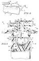
- FIG. 2is an exploded perspective view of a tank vent valve in accordance with the present invention showing a baffle positioned between a primary liquid separation chamber and an auxiliary liquid separation chamber to create an obstacle to and divert the flow of liquid fuel flowing from a float chamber and through a venting outlet;
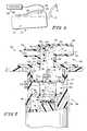
- FIG. 3is an inverted bottom view of a valve lid of FIG. 2 showing a diversion baffle positioned between an outlet port and an inlet port to downwardly divert fuel entering from the inlet port;
- FIG. 4is a side view of a fuel tank canted in a first direction and showing a first vent valve immersed in liquid fuel and a second vent valve above the level of liquid fuel in the tank;
- FIG. 6is a side view of a fuel tank canted in a direction opposite as that shown in FIG. 5, showing the second vent valve immersed in liquid fuel and the first vent valve above the level of liquid fuel in the tank;
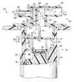
- FIG. 7is an enlarged side view, with portions cut away, showing a tank vent valve according to the present invention showing liquid fuel splashing up through a venting outlet in the first vent valve and contacting a protector floor of the baffle, and additional liquid fuel splashing through apertures in the protector floor and contacting a top wall and ceiling of an auxiliary liquid separation chamber and falling back down through the tank vent valve.
- a tank valve 30includes a valve housing or valve container 36 which is adapted to be installed in a fuel tank, an upper housing or valve lid 56 , a baffle plate or slosh protector 50 , a valve assembly or float valve 72 , a retainer 84 and a base 86 having pin holes 88 formed therein.
- the valve assembly 72includes intermediate wall 46 having a venting outlet 48 , float valve 74 , float cage 78 , and spring 82 .
- the valve assembly 72is adapted for movement between an open position allowing flow of fuel vapor through the apparatus 30 and outlet and a closed position preventing flow of at least fuel vapor through the outlet.
- the valve assembly 72controllably provides communication between the inlet 31 and outlet 33 .
- valve container 36defines a main chamber 40 therein.
- Intermediate wall 46divides the main chamber 40 defining a float chamber 44 , bounded one end by intermediate wall 46 coupled to the interior of valve container 36 within main chamber 40 and at the other end by retainer 84 coupled to valve container 36 within the main chamber 40 .
- a float valve 74is slidably positioned to move between a closed position blocking venting outlet 48 formed within intermediate wall 46 and an opened position permitting flow through venting outlet 48 .
- Float valve 72may be any one of several conventional float valves known to those skilled in the art, including a two-stage reopening valve as shown in FIGS. 2, 5 , and 7 and further described in U.S.
- Slosh protector 50is foraminous and further includes multiple apertures 54 in a protector floor 53 which allow fuel vapor 15 to pass therethrough. Apertures 54 are positioned to prevent alignment with the generally centrally located venting outlet 48 in intermediate wall 46 such as near the perimeter of protector floor 53 . Placement of slosh protector 50 within main chamber 40 of valve container 36 further defined above it an auxiliary liquid separation chamber 68 of main chamber 40 . Slosh protector 50 further includes legs 51 at the perimeter of protector floor 53 which surround protector chamber 52 and maintain protector floor 53 in a desired orientation in main chamber 40 such as in spaced-apart relationship with a cover portion 58 of valve lid 56 . Ledges 45 and legs 51 define positioning structures 59 which maintain baffle 50 in a desired orientation in main chamber 40 .
- Valve lid 56is coupled to valve container 36 and is adaptable to be mounted to fuel tank 10 .
- lid 56is formed to include a cover dome 60 which defines a lid chamber 66 therein.
- lid chamber 66cooperates with auxiliary liquid separation chamber 68 to provide further obstruction and diversion for liquid fuel 16 which happens to find its way through apertures 54 in protector floor 53 and into auxiliary slosh chamber 68 .
- liquid fuelwill contact and agglomerate on top wall 67 and ceiling 69 and drain, generally, into main chamber 40 .
- inlet nipple 62defines a second valve passageway 90 which opens through an inlet port 92 into lid chamber 66 and canister nipple 64 defines a canister passageway 94 which opens through an outlet port 96 into lid chamber 66 .
- Inlet port 92 , lid chamber 66 and outlet port 96define generally a flow path 97 from second valve 32 to canister 34 .
- Diversion baffle 70is oriented in lid chamber 66 to drain into auxiliary separation chamber 68 .
- Diversion baffle 70is positioned in lid chamber 66 to define an input chamber 99 between inlet port 92 and diversion baffle 70 and an output chamber 101 between outlet port 96 and diversion baffle 70 .
- Diversion baffle 70extends a dimension 103 for producing an obstacle preventing direct flow from the inlet port 92 , through lid chamber 66 and out outlet port 96 .
- input chamber 99has a volume which is less than a correspondingly measured volume of outlet port 96 to help promote agglomeration of fuel on diversion baffle 70 .
- the volume differentialreduces the velocity of liquid fuel and vapor to promote interception and separation of liquid.
- vent valve 30is at least partially and temporarily immersed or submersed in liquid fuel 16 , thereby closing float valve assembly 74 within float chamber 44 of vent valve 30 , as shown in FIG. 5 .
- second vent valve 32is above the level of liquid fuel 16 in the fuel tank 10 and, therefore, a float valve (not shown) within it will remain open.
- rapid sloshing of liquid fuel 16 within tank 10may cause liquid fuel 16 to shoot up to second vent valve 32 and escape through it before a float valve within second vent valve 32 has time to close. This results in some liquid fuel 16 traveling from second vent valve 32 through a fuel vapor bridge 26 (as shown in FIG. 4) to inlet nipple 62 of vent valve 30 .
- liquid fuel 16 entering through second valve passageway 90agglomerates on, and is diverted by, diversion baffle 70 causing liquid fuel 16 collected thereon to travel along or drip down diversion baffle 70 , through main chamber 40 , and back into fuel tank 10 .
- float valve 72 within vent valve 30will preferably quickly float closed to prevent liquid fuel 16 from traveling through vent valve 30 , through fuel vapor conduit 28 , and to canister 34 . However, because float valve 72 may not immediately float closed, some liquid fuel 16 may have an opportunity to pass through venting outlet 48 of vent valve 30 .
Landscapes
- Engineering & Computer Science (AREA)
- General Engineering & Computer Science (AREA)
- Mechanical Engineering (AREA)
- Life Sciences & Earth Sciences (AREA)
- Sustainable Development (AREA)
- Sustainable Energy (AREA)
- Chemical & Material Sciences (AREA)
- Combustion & Propulsion (AREA)
- Transportation (AREA)
- Supplying Secondary Fuel Or The Like To Fuel, Air Or Fuel-Air Mixtures (AREA)
- Cooling, Air Intake And Gas Exhaust, And Fuel Tank Arrangements In Propulsion Units (AREA)
Abstract
Description
Claims (10)
Priority Applications (1)
| Application Number | Priority Date | Filing Date | Title |
|---|---|---|---|
| US09/697,842US6405747B1 (en) | 1999-10-29 | 2000-10-27 | Fuel tank vent valve with liquid carryover filter |
Applications Claiming Priority (2)
| Application Number | Priority Date | Filing Date | Title |
|---|---|---|---|
| US16272399P | 1999-10-29 | 1999-10-29 | |
| US09/697,842US6405747B1 (en) | 1999-10-29 | 2000-10-27 | Fuel tank vent valve with liquid carryover filter |
Publications (1)
| Publication Number | Publication Date |
|---|---|
| US6405747B1true US6405747B1 (en) | 2002-06-18 |
Family
ID=26859013
Family Applications (1)
| Application Number | Title | Priority Date | Filing Date |
|---|---|---|---|
| US09/697,842Expired - LifetimeUS6405747B1 (en) | 1999-10-29 | 2000-10-27 | Fuel tank vent valve with liquid carryover filter |
Country Status (1)
| Country | Link |
|---|---|
| US (1) | US6405747B1 (en) |
Cited By (45)
| Publication number | Priority date | Publication date | Assignee | Title |
|---|---|---|---|---|
| US20020083974A1 (en)* | 2000-12-19 | 2002-07-04 | Ewald Duermeier | Ventilation and/or pressure-equalizing system for a fuel tank |
| US20020112907A1 (en)* | 2001-01-31 | 2002-08-22 | Kazuhiro Maeda | Breather system and straddle-type four wheeled all terrain vehicle comprising breather system |
| US20020121300A1 (en)* | 2001-03-01 | 2002-09-05 | Moshe Ehrman | Liquid fuel trap |
| US6675779B2 (en) | 2002-06-13 | 2004-01-13 | Stant Manufacturing Inc. | Dual float valve for fuel tank vent with liquid carryover filter |
| US20040056482A1 (en)* | 2000-11-02 | 2004-03-25 | Kazumasa Kurihara | Fuel tank connector |
| US20040055582A1 (en)* | 2002-09-11 | 2004-03-25 | Honda Giken Kogyo Kabushiki Kaisha | Fuel vapor processing system |
| US20050022898A1 (en)* | 2003-08-01 | 2005-02-03 | Williamson Brian J. | Fuel tank vent system |
| US20050139260A1 (en)* | 2003-09-29 | 2005-06-30 | Alfmeier Prazision Ag Baugruppen Und Systemlosungen | Motor vehicle tank with air venting |
| US20060096258A1 (en)* | 2004-11-05 | 2006-05-11 | Ti Automotive Fuel Systems Sas | Fuel tank ventilation device |
| JP2007333136A (en)* | 2006-06-16 | 2007-12-27 | Piolax Inc | Liquid shut-off valve device |
| DE202008001586U1 (en) | 2007-02-05 | 2008-06-12 | Raval - Agriculture Cooperative Societies Ltd. | Liquid vapor separator |
| US20090025822A1 (en)* | 2007-07-27 | 2009-01-29 | Rittershofer Frank U | Liquid separator |
| US20090084449A1 (en)* | 2007-10-02 | 2009-04-02 | Piolax Inc. | Float valve device |
| US20090293962A1 (en)* | 2008-05-30 | 2009-12-03 | Toyoda Gosei Co., Ltd. | Fuel cutoff valve |
| US20100071785A1 (en)* | 2008-09-19 | 2010-03-25 | Toyoda Gosei Co., Ltd. | Fuel cutoff valve |
| US20100089466A1 (en)* | 2007-04-26 | 2010-04-15 | Nifco Inc. | Valve device for fuel tank |
| US20100108155A1 (en)* | 2007-04-26 | 2010-05-06 | Yasutomo Kobayashi | Fuel tank valve device |
| US20120298534A1 (en)* | 2011-05-24 | 2012-11-29 | Toyota Jidosha Kabushiki Kaisha | Fuel tank structure |
| US20120305555A1 (en)* | 2010-01-07 | 2012-12-06 | Kautex Textron Gmbh & Co. Kg | Drop separator |
| CN103477135A (en)* | 2011-01-31 | 2013-12-25 | 拉瓦尔农业合作社有限公司 | Fuel valve |
| WO2014030160A1 (en) | 2012-08-20 | 2014-02-27 | Raval A.C.S. Ltd. | Vehicle fuel accessory |
| US20140318505A1 (en)* | 2011-08-25 | 2014-10-30 | Eaton Industrial IP GmbH & Co. KG | Liquid fuel trap device |
| EP2832571A1 (en)* | 2013-08-01 | 2015-02-04 | TI Automotive Technology Center GmbH | Closed tank system |
| WO2015101750A1 (en) | 2013-12-30 | 2015-07-09 | Inergy Automotive Systems Research (Société Anonyme) | Nozzle for filling a fuel tank, comprising a liquid-vapour separator having two positions |
| US20150252760A1 (en)* | 2014-03-05 | 2015-09-10 | Piolax, Inc. | Valve device for fuel tank |
| US20150377196A1 (en)* | 2014-03-17 | 2015-12-31 | Kyosan Denki Co., Ltd. | Liquid fuel catcher |
| CN106438116A (en)* | 2015-08-07 | 2017-02-22 | 京三电机株式会社 | Liquid fuel catcher |
| US9614210B2 (en) | 2014-09-30 | 2017-04-04 | Johnson Controls Technology Company | Battery module vent system and method |
| EP3178687A1 (en) | 2015-12-08 | 2017-06-14 | Plastic Omnium Advanced Innovation and Research | Valve apparatus for venting a liquid tank |
| US20170328311A1 (en)* | 2016-05-16 | 2017-11-16 | Eaton Corporation | Fuel system control |
| US20170334286A1 (en)* | 2016-05-23 | 2017-11-23 | Yamaha Hatsudoki Kabushiki Kaisha | Fuel tank |
| US9950616B2 (en) | 2010-12-03 | 2018-04-24 | Jeffrey Yager | Deployable fuel tank baffle and fuel tank system |
| WO2018085325A1 (en)* | 2016-11-02 | 2018-05-11 | Eaton Corporation | Fill limit venting valve with high shut-off height |
| US10006413B2 (en) | 2015-07-09 | 2018-06-26 | Ford Global Technologies, Llc | Systems and methods for detection and mitigation of liquid fuel carryover in an evaporative emissions system |
| US10023047B2 (en)* | 2016-05-23 | 2018-07-17 | Yamaha Hatsudoki Kabushiki Kaisha | Four-wheel vehicle |
| CN109340412A (en)* | 2018-11-27 | 2019-02-15 | 戴胜汽车科技(苏州)有限公司 | The combination valve with hydrops function on automotive oil tank |
| US20190126743A1 (en)* | 2017-10-31 | 2019-05-02 | Hyundai Motor Company | Leveling nipple for tank capable of preventing spit-back |
| US20190338844A1 (en)* | 2018-05-01 | 2019-11-07 | Bell Helicopter Textron Inc. | Gearbox filler assembly |
| USD899458S1 (en) | 2017-02-16 | 2020-10-20 | Eaton Corporation | Fill limit venting valve with high shut-off height |
| US11091027B2 (en) | 2016-06-09 | 2021-08-17 | Eaton Intelligent Power Limited | Electronic fuel tank system having cam actuated venting with canister line isolation |
| US11135913B2 (en)* | 2017-03-16 | 2021-10-05 | Piolax, Inc. | Fuel tank valve device |
| US11155159B2 (en)* | 2019-10-10 | 2021-10-26 | Nifco Inc. | Fuel tank valve apparatus |
| US11285804B2 (en)* | 2019-05-15 | 2022-03-29 | Magna Energy Storage Systems Gesmbh | Venting device for venting a motor vehicle tank |
| US20220105797A1 (en)* | 2019-04-01 | 2022-04-07 | Raval A.C.S. Ltd. | Venting systems and methods |
| US11698045B2 (en) | 2014-09-24 | 2023-07-11 | Eaton Intelligent Power Limited | Electrically controlled fuel system module |
Citations (23)
| Publication number | Priority date | Publication date | Assignee | Title |
|---|---|---|---|---|
| US3152604A (en)* | 1963-06-21 | 1964-10-13 | Coca Cola Co | Vent valve assembly |
| US4685584A (en)* | 1986-09-29 | 1987-08-11 | Stant Inc. | Vented fuel cap with bump and grade seal |
| US4760858A (en) | 1986-03-07 | 1988-08-02 | Stant Inc. | Fuel vapor control valve |
| US4816045A (en) | 1986-03-31 | 1989-03-28 | Stant Inc. | Vapor recovery system |
| US4826511A (en) | 1986-03-31 | 1989-05-02 | Stant Inc. | Vapor recovery system |
| US4953583A (en) | 1989-03-24 | 1990-09-04 | Stant Inc. | Tank pressure control valve |
| US5028244A (en) | 1990-06-27 | 1991-07-02 | Stant Inc. | Tank venting control valve assembly |
| US5156178A (en) | 1991-02-22 | 1992-10-20 | Stant Inc. | Vacuum-actuated vent assembly |
| US5215132A (en) | 1991-05-31 | 1993-06-01 | Nissan Motor Co., Ltd. | Valve device for fuel tank |
| US5234013A (en) | 1992-07-07 | 1993-08-10 | Stant Manufacturing Inc. | Tank venting control assembly |
| US5261439A (en) | 1991-02-22 | 1993-11-16 | Stant Manufacturing Inc. | Vacuum-actuated vent assembly |
| US5318069A (en) | 1992-01-17 | 1994-06-07 | Stant Manufacturing Inc. | Tank venting and vapor recovery system |
| US5566705A (en) | 1995-06-30 | 1996-10-22 | Stant Manufacturing Inc. | Snap-closure float valve assembly |
| US5577526A (en) | 1994-04-28 | 1996-11-26 | Toyoda Gosei Co., Ltd. | Float valve for fuel tank |
| US5687778A (en) | 1995-05-01 | 1997-11-18 | Stant Manufacturing Inc. | Dual valve tank venting system |
| US5694968A (en) | 1996-04-15 | 1997-12-09 | Stant Manufacturing Inc. | Tank venting control system |
| DE19628583A1 (en) | 1996-03-09 | 1998-01-22 | Fritz Curtius | Method for treatment of liquid droplets from vehicle fuel |
| US5762093A (en)* | 1995-03-29 | 1998-06-09 | Attwood Corporation | Fuel overflow restrictor/water intake restraining devices |
| US5782258A (en) | 1995-12-11 | 1998-07-21 | Alfmeier Corporation | Vapor recovery fuel tank system |
| US5927315A (en)* | 1996-12-02 | 1999-07-27 | Hyundai Motor Company | Fuel leakage prevention apparatus |
| US5944044A (en) | 1996-05-10 | 1999-08-31 | Stant Manufacturing Inc. | Tank venting control system |
| US6035884A (en) | 1997-09-16 | 2000-03-14 | Stant Manufacturing Inc. | Liquid fuel baffle for vent apparatus |
| US6158456A (en)* | 1999-04-28 | 2000-12-12 | Borgwarner Inc. | Vehicle refueling valve |
- 2000
- 2000-10-27USUS09/697,842patent/US6405747B1/ennot_activeExpired - Lifetime
Patent Citations (23)
| Publication number | Priority date | Publication date | Assignee | Title |
|---|---|---|---|---|
| US3152604A (en)* | 1963-06-21 | 1964-10-13 | Coca Cola Co | Vent valve assembly |
| US4760858A (en) | 1986-03-07 | 1988-08-02 | Stant Inc. | Fuel vapor control valve |
| US4816045A (en) | 1986-03-31 | 1989-03-28 | Stant Inc. | Vapor recovery system |
| US4826511A (en) | 1986-03-31 | 1989-05-02 | Stant Inc. | Vapor recovery system |
| US4685584A (en)* | 1986-09-29 | 1987-08-11 | Stant Inc. | Vented fuel cap with bump and grade seal |
| US4953583A (en) | 1989-03-24 | 1990-09-04 | Stant Inc. | Tank pressure control valve |
| US5028244A (en) | 1990-06-27 | 1991-07-02 | Stant Inc. | Tank venting control valve assembly |
| US5261439A (en) | 1991-02-22 | 1993-11-16 | Stant Manufacturing Inc. | Vacuum-actuated vent assembly |
| US5156178A (en) | 1991-02-22 | 1992-10-20 | Stant Inc. | Vacuum-actuated vent assembly |
| US5215132A (en) | 1991-05-31 | 1993-06-01 | Nissan Motor Co., Ltd. | Valve device for fuel tank |
| US5318069A (en) | 1992-01-17 | 1994-06-07 | Stant Manufacturing Inc. | Tank venting and vapor recovery system |
| US5234013A (en) | 1992-07-07 | 1993-08-10 | Stant Manufacturing Inc. | Tank venting control assembly |
| US5577526A (en) | 1994-04-28 | 1996-11-26 | Toyoda Gosei Co., Ltd. | Float valve for fuel tank |
| US5762093A (en)* | 1995-03-29 | 1998-06-09 | Attwood Corporation | Fuel overflow restrictor/water intake restraining devices |
| US5687778A (en) | 1995-05-01 | 1997-11-18 | Stant Manufacturing Inc. | Dual valve tank venting system |
| US5566705A (en) | 1995-06-30 | 1996-10-22 | Stant Manufacturing Inc. | Snap-closure float valve assembly |
| US5782258A (en) | 1995-12-11 | 1998-07-21 | Alfmeier Corporation | Vapor recovery fuel tank system |
| DE19628583A1 (en) | 1996-03-09 | 1998-01-22 | Fritz Curtius | Method for treatment of liquid droplets from vehicle fuel |
| US5694968A (en) | 1996-04-15 | 1997-12-09 | Stant Manufacturing Inc. | Tank venting control system |
| US5944044A (en) | 1996-05-10 | 1999-08-31 | Stant Manufacturing Inc. | Tank venting control system |
| US5927315A (en)* | 1996-12-02 | 1999-07-27 | Hyundai Motor Company | Fuel leakage prevention apparatus |
| US6035884A (en) | 1997-09-16 | 2000-03-14 | Stant Manufacturing Inc. | Liquid fuel baffle for vent apparatus |
| US6158456A (en)* | 1999-04-28 | 2000-12-12 | Borgwarner Inc. | Vehicle refueling valve |
Non-Patent Citations (1)
| Title |
|---|
| European Search Report for EP00309553.6. |
Cited By (101)
| Publication number | Priority date | Publication date | Assignee | Title |
|---|---|---|---|---|
| US7090262B2 (en) | 2000-11-02 | 2006-08-15 | Nifco, Inc. | Fuel tank connector |
| US6733048B2 (en)* | 2000-11-02 | 2004-05-11 | Nifco, Inc. | Fuel tank connector |
| US20040056482A1 (en)* | 2000-11-02 | 2004-03-25 | Kazumasa Kurihara | Fuel tank connector |
| US6871662B2 (en)* | 2000-12-19 | 2005-03-29 | Daimlerchrysler Ag | Ventilation and/or pressure-equalizing system for a fuel tank |
| US20020083974A1 (en)* | 2000-12-19 | 2002-07-04 | Ewald Duermeier | Ventilation and/or pressure-equalizing system for a fuel tank |
| US6805214B2 (en)* | 2001-01-31 | 2004-10-19 | Kawasaki Jukogyo Kabushiki Kaisha | Breather system and straddle-type four wheeled all terrain vehicle comprising breather system |
| US20020112907A1 (en)* | 2001-01-31 | 2002-08-22 | Kazuhiro Maeda | Breather system and straddle-type four wheeled all terrain vehicle comprising breather system |
| US6557581B2 (en)* | 2001-03-01 | 2003-05-06 | Raviv Precision Injection Molding | Liquid fuel trap |
| US6860285B2 (en) | 2001-03-01 | 2005-03-01 | Raval-Agriculture Cooperative Societies, Ltd. | Liquid fuel trap |
| US20030079775A1 (en)* | 2001-03-01 | 2003-05-01 | Moshe Ehrman | Liquid fuel trap |
| US20020121300A1 (en)* | 2001-03-01 | 2002-09-05 | Moshe Ehrman | Liquid fuel trap |
| US6675779B2 (en) | 2002-06-13 | 2004-01-13 | Stant Manufacturing Inc. | Dual float valve for fuel tank vent with liquid carryover filter |
| US6951209B2 (en)* | 2002-09-11 | 2005-10-04 | Honda Giken Kogyo Kabushiki Kaisha | Fuel vapor processing system |
| US20040055582A1 (en)* | 2002-09-11 | 2004-03-25 | Honda Giken Kogyo Kabushiki Kaisha | Fuel vapor processing system |
| US20050022898A1 (en)* | 2003-08-01 | 2005-02-03 | Williamson Brian J. | Fuel tank vent system |
| US7063101B2 (en) | 2003-08-01 | 2006-06-20 | Stant Manufacturing Inc. | Fuel tank vent system |
| US20050139260A1 (en)* | 2003-09-29 | 2005-06-30 | Alfmeier Prazision Ag Baugruppen Und Systemlosungen | Motor vehicle tank with air venting |
| US7383856B2 (en) | 2003-09-29 | 2008-06-10 | Alfmeier Prazision Ag Baugruppen Und Systemlosungen | Motor vehicle tank with air venting |
| FR2877650A1 (en)* | 2004-11-05 | 2006-05-12 | Marwal Systems Snc | TANK VENTILATION DEVICE |
| US20060096258A1 (en)* | 2004-11-05 | 2006-05-11 | Ti Automotive Fuel Systems Sas | Fuel tank ventilation device |
| US7491258B2 (en) | 2004-11-05 | 2009-02-17 | Ti Automotive Fuel Systems Sas | Fuel tank ventilation device |
| JP2007333136A (en)* | 2006-06-16 | 2007-12-27 | Piolax Inc | Liquid shut-off valve device |
| US20070295403A1 (en)* | 2006-06-16 | 2007-12-27 | Piolax Inc. | Liquid shutoff valve gear |
| US7770594B2 (en)* | 2006-06-16 | 2010-08-10 | Piolax Inc. | Liquid shutoff valve gear |
| DE202008001586U1 (en) | 2007-02-05 | 2008-06-12 | Raval - Agriculture Cooperative Societies Ltd. | Liquid vapor separator |
| US7694665B2 (en) | 2007-02-05 | 2010-04-13 | Raval A.C.S. Ltd. | Liquid vapor separator |
| RU2412830C2 (en)* | 2007-02-05 | 2011-02-27 | Равал А.К.С. Лтд. | Separator of liquid fuel from vapours and transport facility fuel system |
| EP1955888A2 (en) | 2007-02-05 | 2008-08-13 | Raval A.C.S. LTD | Liquid vapor separator |
| US20080184972A1 (en)* | 2007-02-05 | 2008-08-07 | Raval A.C.S. Ltd. | Liquid vapor separator |
| US20100108155A1 (en)* | 2007-04-26 | 2010-05-06 | Yasutomo Kobayashi | Fuel tank valve device |
| EP2163757A4 (en)* | 2007-04-26 | 2011-02-16 | Nifco Inc | VALVE DEVICE FOR A FUEL TANK |
| CN101680400B (en)* | 2007-04-26 | 2014-07-02 | 株式会社利富高 | Valve device for fuel tank |
| US20100089466A1 (en)* | 2007-04-26 | 2010-04-15 | Nifco Inc. | Valve device for fuel tank |
| US8365757B2 (en) | 2007-04-26 | 2013-02-05 | Nifco Inc. | Valve device for fuel tank |
| CN101680401B (en)* | 2007-04-26 | 2012-09-05 | 株式会社利富高 | Valve device for fuel tank |
| EP2143933A4 (en)* | 2007-04-26 | 2011-02-16 | Nifco Inc | Valve device for fuel tank |
| US8365756B2 (en) | 2007-04-26 | 2013-02-05 | Nifco Inc. | Fuel tank valve device |
| JP2010534793A (en)* | 2007-07-27 | 2010-11-11 | ティーアイ グループ オートモーティヴ システムズ リミテッド ライアビリティー カンパニー | Liquid separator |
| US7779820B2 (en)* | 2007-07-27 | 2010-08-24 | Ti Group Automotive Systems, L.L.C. | Liquid separator |
| WO2009018002A1 (en)* | 2007-07-27 | 2009-02-05 | Ti Group Automotive Systems, L.L.C. | Liquid separator |
| US20090025822A1 (en)* | 2007-07-27 | 2009-01-29 | Rittershofer Frank U | Liquid separator |
| KR101462182B1 (en)* | 2007-07-27 | 2014-11-14 | 티아이 그룹 오토모티브 시스템즈 엘엘씨 | Liquid separator |
| US20090084449A1 (en)* | 2007-10-02 | 2009-04-02 | Piolax Inc. | Float valve device |
| US8844557B2 (en)* | 2007-10-02 | 2014-09-30 | Piolax Inc. | Float valve device |
| US8042564B2 (en) | 2008-05-30 | 2011-10-25 | Toyoda Gosei Co., Ltd. | Fuel cutoff valve |
| US20090293962A1 (en)* | 2008-05-30 | 2009-12-03 | Toyoda Gosei Co., Ltd. | Fuel cutoff valve |
| US20100071785A1 (en)* | 2008-09-19 | 2010-03-25 | Toyoda Gosei Co., Ltd. | Fuel cutoff valve |
| US8813781B2 (en)* | 2010-01-07 | 2014-08-26 | Kautex Textron Gmbh & Co. Kg | Drop separator |
| US20120305555A1 (en)* | 2010-01-07 | 2012-12-06 | Kautex Textron Gmbh & Co. Kg | Drop separator |
| US9950616B2 (en) | 2010-12-03 | 2018-04-24 | Jeffrey Yager | Deployable fuel tank baffle and fuel tank system |
| CN103477135A (en)* | 2011-01-31 | 2013-12-25 | 拉瓦尔农业合作社有限公司 | Fuel valve |
| US9393862B2 (en) | 2011-01-31 | 2016-07-19 | Raval A.C.S. Ltd. | Fuel valve |
| US9079488B2 (en)* | 2011-05-24 | 2015-07-14 | Toyota Jidosha Kabushiki Kaisha | Fuel tank structure |
| US20120298534A1 (en)* | 2011-05-24 | 2012-11-29 | Toyota Jidosha Kabushiki Kaisha | Fuel tank structure |
| US20140318505A1 (en)* | 2011-08-25 | 2014-10-30 | Eaton Industrial IP GmbH & Co. KG | Liquid fuel trap device |
| US9248735B2 (en)* | 2011-08-25 | 2016-02-02 | Eaton Corporation | Liquid fuel trap device |
| KR20150047526A (en)* | 2012-08-20 | 2015-05-04 | 라발 에이.씨.에스. 엘티디 | Vehicle fuel accessory |
| US10465634B2 (en) | 2012-08-20 | 2019-11-05 | Raval A.C.S. Ltd. | Vehicle fuel accessory |
| WO2014030160A1 (en) | 2012-08-20 | 2014-02-27 | Raval A.C.S. Ltd. | Vehicle fuel accessory |
| RU2640904C2 (en)* | 2012-08-20 | 2018-01-12 | РАВАЛ Эй.Си.Эс. ЛТД. | Auxiliary device of vehicle fuel system |
| KR102124668B1 (en) | 2012-08-20 | 2020-06-19 | 라발 에이.씨.에스. 엘티디 | Vehicle fuel accessory |
| US9428044B2 (en) | 2013-08-01 | 2016-08-30 | Ti Automotive Technology Center Gmbh | Closed tank system |
| EP2832571A1 (en)* | 2013-08-01 | 2015-02-04 | TI Automotive Technology Center GmbH | Closed tank system |
| WO2015101750A1 (en) | 2013-12-30 | 2015-07-09 | Inergy Automotive Systems Research (Société Anonyme) | Nozzle for filling a fuel tank, comprising a liquid-vapour separator having two positions |
| JP2015180815A (en)* | 2014-03-05 | 2015-10-15 | 株式会社パイオラックス | Valve device for fuel tank |
| US20150252760A1 (en)* | 2014-03-05 | 2015-09-10 | Piolax, Inc. | Valve device for fuel tank |
| US10267275B2 (en)* | 2014-03-05 | 2019-04-23 | Piolax, Inc. | Valve device for fuel tank |
| US10035091B2 (en)* | 2014-03-17 | 2018-07-31 | Kyosan Denki Co., Ltd. | Liquid fuel catcher |
| US20150377196A1 (en)* | 2014-03-17 | 2015-12-31 | Kyosan Denki Co., Ltd. | Liquid fuel catcher |
| US11698045B2 (en) | 2014-09-24 | 2023-07-11 | Eaton Intelligent Power Limited | Electrically controlled fuel system module |
| US9614210B2 (en) | 2014-09-30 | 2017-04-04 | Johnson Controls Technology Company | Battery module vent system and method |
| US10006413B2 (en) | 2015-07-09 | 2018-06-26 | Ford Global Technologies, Llc | Systems and methods for detection and mitigation of liquid fuel carryover in an evaporative emissions system |
| CN106438116B (en)* | 2015-08-07 | 2019-12-27 | 京三电机株式会社 | Liquid fuel catcher |
| CN106438116A (en)* | 2015-08-07 | 2017-02-22 | 京三电机株式会社 | Liquid fuel catcher |
| CN108367672A (en)* | 2015-12-08 | 2018-08-03 | 全耐塑料高级创新研究公司 | Valve equipment for venting liquid tanks |
| WO2017097841A1 (en)* | 2015-12-08 | 2017-06-15 | Plastic Omnium Advanced Innovation And Research | Valve apparatus for venting a liquid tank |
| EP3178687A1 (en) | 2015-12-08 | 2017-06-14 | Plastic Omnium Advanced Innovation and Research | Valve apparatus for venting a liquid tank |
| US10632837B2 (en)* | 2015-12-08 | 2020-04-28 | Plastic Omnium Advanced Innovation And Research | Valve apparatus for venting a liquid tank |
| US11092113B2 (en) | 2016-05-16 | 2021-08-17 | Eaton Intelligent Power Limited | Fuel system control |
| US11542893B2 (en) | 2016-05-16 | 2023-01-03 | Eaton Intelligent Power Limited | Fuel system control |
| US20170328311A1 (en)* | 2016-05-16 | 2017-11-16 | Eaton Corporation | Fuel system control |
| US10662900B2 (en)* | 2016-05-16 | 2020-05-26 | Eaton Corporation | Fuel system control |
| US10919379B2 (en)* | 2016-05-23 | 2021-02-16 | Yamaha Hatsudoki Kabushiki Kaisha | Fuel tank |
| US20170334286A1 (en)* | 2016-05-23 | 2017-11-23 | Yamaha Hatsudoki Kabushiki Kaisha | Fuel tank |
| US10023047B2 (en)* | 2016-05-23 | 2018-07-17 | Yamaha Hatsudoki Kabushiki Kaisha | Four-wheel vehicle |
| US11091027B2 (en) | 2016-06-09 | 2021-08-17 | Eaton Intelligent Power Limited | Electronic fuel tank system having cam actuated venting with canister line isolation |
| CN110072723A (en)* | 2016-11-02 | 2019-07-30 | 伊顿智能动力有限公司 | Exhaust valve is limited with the high filling for closing height |
| US11560049B2 (en) | 2016-11-02 | 2023-01-24 | Eaton Intelligent Power Limited | Fill limit venting valve with high shut-off height |
| WO2018085325A1 (en)* | 2016-11-02 | 2018-05-11 | Eaton Corporation | Fill limit venting valve with high shut-off height |
| US11059368B2 (en) | 2016-11-02 | 2021-07-13 | Eaton Intelligent Power Limited | Fill limit venting valve with high shut-off height |
| USD899458S1 (en) | 2017-02-16 | 2020-10-20 | Eaton Corporation | Fill limit venting valve with high shut-off height |
| US11135913B2 (en)* | 2017-03-16 | 2021-10-05 | Piolax, Inc. | Fuel tank valve device |
| US10632838B2 (en)* | 2017-10-31 | 2020-04-28 | Hyundai Motor Company | Leveling nipple for tank capable of preventing spit-back |
| US20190126743A1 (en)* | 2017-10-31 | 2019-05-02 | Hyundai Motor Company | Leveling nipple for tank capable of preventing spit-back |
| US10830333B2 (en)* | 2018-05-01 | 2020-11-10 | Bell Helicopter Textron Inc. | Gearbox filler assembly |
| US20190338844A1 (en)* | 2018-05-01 | 2019-11-07 | Bell Helicopter Textron Inc. | Gearbox filler assembly |
| CN109340412A (en)* | 2018-11-27 | 2019-02-15 | 戴胜汽车科技(苏州)有限公司 | The combination valve with hydrops function on automotive oil tank |
| CN109340412B (en)* | 2018-11-27 | 2024-03-08 | 戴胜汽车科技(苏州)有限公司 | Combined valve with hydrops function for automobile oil tank |
| US20220105797A1 (en)* | 2019-04-01 | 2022-04-07 | Raval A.C.S. Ltd. | Venting systems and methods |
| US11285804B2 (en)* | 2019-05-15 | 2022-03-29 | Magna Energy Storage Systems Gesmbh | Venting device for venting a motor vehicle tank |
| US11155159B2 (en)* | 2019-10-10 | 2021-10-26 | Nifco Inc. | Fuel tank valve apparatus |
Similar Documents
| Publication | Publication Date | Title |
|---|---|---|
| US6405747B1 (en) | Fuel tank vent valve with liquid carryover filter | |
| US5669361A (en) | Vehicle refueling valve | |
| US6035884A (en) | Liquid fuel baffle for vent apparatus | |
| US5065782A (en) | Tank venting control assembly | |
| US6578597B2 (en) | Fuel tank vent system with liquid fuel filter | |
| US5694968A (en) | Tank venting control system | |
| US5687778A (en) | Dual valve tank venting system | |
| US5449029A (en) | Fill limit valve assembly | |
| US5535772A (en) | Tank venting control system | |
| US5028244A (en) | Tank venting control valve assembly | |
| US7188613B2 (en) | Fuel cut off valve | |
| US5261439A (en) | Vacuum-actuated vent assembly | |
| US6918405B2 (en) | Fill limit vent valve | |
| US5116257A (en) | Tank venting control assembly | |
| US5156178A (en) | Vacuum-actuated vent assembly | |
| US6170510B1 (en) | Tank venting control system | |
| EP0648637A1 (en) | Vapour recovery system | |
| US5413137A (en) | Fuel vapor vent assembly with liquid trap | |
| US5868119A (en) | Fuel tank venting system for vehicles | |
| JP4467134B2 (en) | Vehicle fuel supply valve | |
| US5782262A (en) | Gas ventilation apparatus for a fuel tank | |
| US6336466B1 (en) | System for the venting of a liquid tank | |
| KR101266653B1 (en) | Shutoff valve for mechanically sealed orvr system | |
| CN101782159A (en) | Dual Function Valves for Fuel Tanks | |
| US11560049B2 (en) | Fill limit venting valve with high shut-off height |
Legal Events
| Date | Code | Title | Description |
|---|---|---|---|
| AS | Assignment | Owner name:STANT MANUFACTURING, INC, INDIANA Free format text:ASSIGNMENT OF ASSIGNORS INTEREST;ASSIGNORS:KING, THIMOTHY J.;BROWN, GREGORY P.;REEL/FRAME:011539/0389 Effective date:20010209 | |
| STCF | Information on status: patent grant | Free format text:PATENTED CASE | |
| FPAY | Fee payment | Year of fee payment:4 | |
| AS | Assignment | Owner name:GMAC COMMERICAL FINANCE LLC, AS AGENT, NEW YORK Free format text:SECURITY AGREEMENT;ASSIGNORS:STANT CORPORATION;STANDARD-THOMSON CORPORATION;STANT MANUFACTURING INC.;REEL/FRAME:021158/0232 Effective date:20080618 Owner name:GMAC COMMERICAL FINANCE LLC, AS AGENT,NEW YORK Free format text:SECURITY AGREEMENT;ASSIGNORS:STANT CORPORATION;STANDARD-THOMSON CORPORATION;STANT MANUFACTURING INC.;REEL/FRAME:021158/0232 Effective date:20080618 | |
| AS | Assignment | Owner name:STANT USA CORP., INDIANA Free format text:ASSIGNMENT OF ASSIGNORS INTEREST;ASSIGNOR:STANT MANUFACTURING INC.;REEL/FRAME:023471/0086 Effective date:20091027 Owner name:STANT USA CORP.,INDIANA Free format text:ASSIGNMENT OF ASSIGNORS INTEREST;ASSIGNOR:STANT MANUFACTURING INC.;REEL/FRAME:023471/0086 Effective date:20091027 | |
| AS | Assignment | Owner name:GMAC COMMERICAL FINANCE LLC, AS AGENT, ILLINOIS Free format text:SECURITY AGREEMENT;ASSIGNOR:STANT USA CORP.;REEL/FRAME:023498/0035 Effective date:20091027 Owner name:GMAC COMMERICAL FINANCE LLC, AS AGENT,ILLINOIS Free format text:SECURITY AGREEMENT;ASSIGNOR:STANT USA CORP.;REEL/FRAME:023498/0035 Effective date:20091027 | |
| AS | Assignment | Owner name:STANT CORPORATION, INDIANA Free format text:RELEASE BY SECURED PARTY;ASSIGNOR:GMAC COMMERICAL FINANCE LLC, AS AGENT;REEL/FRAME:023498/0499 Effective date:20091027 Owner name:STANDARD-THOMSON, INDIANA Free format text:RELEASE BY SECURED PARTY;ASSIGNOR:GMAC COMMERICAL FINANCE LLC, AS AGENT;REEL/FRAME:023498/0499 Effective date:20091027 Owner name:STANT MANUFACTURING INC., INDIANA Free format text:RELEASE BY SECURED PARTY;ASSIGNOR:GMAC COMMERICAL FINANCE LLC, AS AGENT;REEL/FRAME:023498/0499 Effective date:20091027 Owner name:STANT CORPORATION,INDIANA Free format text:RELEASE BY SECURED PARTY;ASSIGNOR:GMAC COMMERICAL FINANCE LLC, AS AGENT;REEL/FRAME:023498/0499 Effective date:20091027 Owner name:STANDARD-THOMSON,INDIANA Free format text:RELEASE BY SECURED PARTY;ASSIGNOR:GMAC COMMERICAL FINANCE LLC, AS AGENT;REEL/FRAME:023498/0499 Effective date:20091027 Owner name:STANT MANUFACTURING INC.,INDIANA Free format text:RELEASE BY SECURED PARTY;ASSIGNOR:GMAC COMMERICAL FINANCE LLC, AS AGENT;REEL/FRAME:023498/0499 Effective date:20091027 | |
| FPAY | Fee payment | Year of fee payment:8 | |
| FPAY | Fee payment | Year of fee payment:12 | |
| AS | Assignment | Owner name:CERBERUS BUSINESS FINANCE, LLC, AS COLLATERAL AGEN Free format text:GRANT OF A SECURITY INTEREST -- PATENTS;ASSIGNOR:STANT USA CORP.;REEL/FRAME:032972/0152 Effective date:20140514 Owner name:STANT USA CORP., INDIANA Free format text:RELEASE OF GRANT OF A SECURITY INTEREST -- PATENTS;ASSIGNOR:ALLY COMMERCIAL FINANCE LLC (FORMERLY KNOWN AS GMAC COMMERCIAL FINANCE LLC);REEL/FRAME:032982/0598 Effective date:20140514 |