US6405733B1 - Device for accurately marking tissue - Google Patents
Device for accurately marking tissueDownload PDFInfo
- Publication number
- US6405733B1 US6405733B1US09/613,686US61368600AUS6405733B1US 6405733 B1US6405733 B1US 6405733B1US 61368600 AUS61368600 AUS 61368600AUS 6405733 B1US6405733 B1US 6405733B1
- Authority
- US
- United States
- Prior art keywords
- tissue
- locator element
- pusher
- lumen
- locator
- Prior art date
- Legal status (The legal status is an assumption and is not a legal conclusion. Google has not performed a legal analysis and makes no representation as to the accuracy of the status listed.)
- Expired - Lifetime, expires
Links
- 230000033001locomotionEffects0.000claimsdescription23
- 230000002441reversible effectEffects0.000claimsdescription12
- 238000004891communicationMethods0.000claimsdescription7
- 230000008713feedback mechanismEffects0.000claimsdescription3
- 238000000034methodMethods0.000abstractdescription79
- 230000000149penetrating effectEffects0.000abstractdescription17
- 210000001519tissueAnatomy0.000description528
- 230000003902lesionEffects0.000description87
- 238000005520cutting processMethods0.000description63
- 210000000481breastAnatomy0.000description40
- 239000000463materialSubstances0.000description29
- 238000013461designMethods0.000description17
- 230000004807localizationEffects0.000description16
- 238000001574biopsyMethods0.000description14
- 230000007246mechanismEffects0.000description14
- 230000037361pathwayEffects0.000description12
- 208000004434CalcinosisDiseases0.000description11
- 238000004873anchoringMethods0.000description11
- 229910001000nickel titaniumInorganic materials0.000description11
- 238000009413insulationMethods0.000description10
- 238000013459approachMethods0.000description9
- 238000006073displacement reactionMethods0.000description9
- 230000008901benefitEffects0.000description8
- 230000008569processEffects0.000description8
- 239000000523sampleSubstances0.000description8
- 238000007514turningMethods0.000description8
- 239000011248coating agentSubstances0.000description7
- 238000000576coating methodMethods0.000description7
- 238000007906compressionMethods0.000description7
- HLXZNVUGXRDIFK-UHFFFAOYSA-Nnickel titaniumChemical compound[Ti].[Ti].[Ti].[Ti].[Ti].[Ti].[Ti].[Ti].[Ti].[Ti].[Ti].[Ni].[Ni].[Ni].[Ni].[Ni].[Ni].[Ni].[Ni].[Ni].[Ni].[Ni].[Ni].[Ni].[Ni]HLXZNVUGXRDIFK-UHFFFAOYSA-N0.000description7
- 239000010935stainless steelSubstances0.000description7
- 229910001220stainless steelInorganic materials0.000description7
- 230000007704transitionEffects0.000description7
- 229910045601alloyInorganic materials0.000description6
- 239000000956alloySubstances0.000description6
- 230000006835compressionEffects0.000description6
- BASFCYQUMIYNBI-UHFFFAOYSA-NplatinumChemical compound[Pt]BASFCYQUMIYNBI-UHFFFAOYSA-N0.000description6
- 239000012790adhesive layerSubstances0.000description5
- 238000003384imaging methodMethods0.000description5
- 230000001788irregularEffects0.000description5
- 239000002184metalSubstances0.000description5
- WYTGDNHDOZPMIW-RCBQFDQVSA-NalstonineNatural productsC1=CC2=C3C=CC=CC3=NC2=C2N1C[C@H]1[C@H](C)OC=C(C(=O)OC)[C@H]1C2WYTGDNHDOZPMIW-RCBQFDQVSA-N0.000description4
- 239000003795chemical substances by applicationSubstances0.000description4
- 239000002131composite materialSubstances0.000description4
- 230000006378damageEffects0.000description4
- 230000000694effectsEffects0.000description4
- 239000000314lubricantSubstances0.000description4
- 229910052751metalInorganic materials0.000description4
- 238000001356surgical procedureMethods0.000description4
- WFKWXMTUELFFGS-UHFFFAOYSA-NtungstenChemical compound[W]WFKWXMTUELFFGS-UHFFFAOYSA-N0.000description4
- 229910052721tungstenInorganic materials0.000description4
- 239000010937tungstenSubstances0.000description4
- 206010028980NeoplasmDiseases0.000description3
- 229910000639Spring steelInorganic materials0.000description3
- HZEWFHLRYVTOIW-UHFFFAOYSA-N[Ti].[Ni]Chemical compound[Ti].[Ni]HZEWFHLRYVTOIW-UHFFFAOYSA-N0.000description3
- 230000009471actionEffects0.000description3
- 239000000853adhesiveSubstances0.000description3
- 230000001070adhesive effectEffects0.000description3
- 230000005540biological transmissionEffects0.000description3
- 230000002308calcificationEffects0.000description3
- 238000010276constructionMethods0.000description3
- -1copper-zinc-aluminumChemical compound0.000description3
- 239000000835fiberSubstances0.000description3
- 238000011065in-situ storageMethods0.000description3
- 208000014674injuryDiseases0.000description3
- 239000007788liquidSubstances0.000description3
- 210000004072lungAnatomy0.000description3
- 150000002739metalsChemical class0.000description3
- 210000000056organAnatomy0.000description3
- 229910052697platinumInorganic materials0.000description3
- 229920000642polymerPolymers0.000description3
- 239000012781shape memory materialSubstances0.000description3
- 230000000007visual effectEffects0.000description3
- 206010006187Breast cancerDiseases0.000description2
- 208000026310Breast neoplasmDiseases0.000description2
- NNJVILVZKWQKPM-UHFFFAOYSA-NLidocaineChemical compoundCCN(CC)CC(=O)NC1=C(C)C=CC=C1CNNJVILVZKWQKPM-UHFFFAOYSA-N0.000description2
- KDLHZDBZIXYQEI-UHFFFAOYSA-NPalladiumChemical compound[Pd]KDLHZDBZIXYQEI-UHFFFAOYSA-N0.000description2
- RTAQQCXQSZGOHL-UHFFFAOYSA-NTitaniumChemical compound[Ti]RTAQQCXQSZGOHL-UHFFFAOYSA-N0.000description2
- 208000027418Wounds and injuryDiseases0.000description2
- 239000003570airSubstances0.000description2
- TZCXTZWJZNENPQ-UHFFFAOYSA-Lbarium sulfateChemical compound[Ba+2].[O-]S([O-])(=O)=OTZCXTZWJZNENPQ-UHFFFAOYSA-L0.000description2
- 230000000740bleeding effectEffects0.000description2
- 238000005219brazingMethods0.000description2
- 201000011510cancerDiseases0.000description2
- 230000010261cell growthEffects0.000description2
- 230000008859changeEffects0.000description2
- 229910017052cobaltInorganic materials0.000description2
- 239000010941cobaltSubstances0.000description2
- GUTLYIVDDKVIGB-UHFFFAOYSA-Ncobalt atomChemical compound[Co]GUTLYIVDDKVIGB-UHFFFAOYSA-N0.000description2
- 230000034994deathEffects0.000description2
- 231100000517deathToxicity0.000description2
- 230000001419dependent effectEffects0.000description2
- 230000000916dilatatory effectEffects0.000description2
- 201000010099diseaseDiseases0.000description2
- 208000037265diseases, disorders, signs and symptomsDiseases0.000description2
- 230000001747exhibiting effectEffects0.000description2
- 239000003193general anesthetic agentSubstances0.000description2
- 238000005304joiningMethods0.000description2
- 229960004194lidocaineDrugs0.000description2
- 210000004185liverAnatomy0.000description2
- 238000002595magnetic resonance imagingMethods0.000description2
- 239000003550markerSubstances0.000description2
- 238000005259measurementMethods0.000description2
- 229910001092metal group alloyInorganic materials0.000description2
- 230000001394metastastic effectEffects0.000description2
- 206010061289metastatic neoplasmDiseases0.000description2
- 230000005012migrationEffects0.000description2
- 238000013508migrationMethods0.000description2
- 210000003205muscleAnatomy0.000description2
- 238000013188needle biopsyMethods0.000description2
- 230000035515penetrationEffects0.000description2
- 239000004033plasticSubstances0.000description2
- 239000002243precursorSubstances0.000description2
- 238000007493shaping processMethods0.000description2
- 238000005476solderingMethods0.000description2
- 239000000126substanceSubstances0.000description2
- 229910052719titaniumInorganic materials0.000description2
- 239000010936titaniumSubstances0.000description2
- 230000009466transformationEffects0.000description2
- 230000008733traumaEffects0.000description2
- 238000002604ultrasonographyMethods0.000description2
- 238000007794visualization techniqueMethods0.000description2
- 238000003466weldingMethods0.000description2
- 229910000851Alloy steelInorganic materials0.000description1
- 206010002091AnaesthesiaDiseases0.000description1
- BQCADISMDOOEFD-UHFFFAOYSA-NSilverChemical compound[Ag]BQCADISMDOOEFD-UHFFFAOYSA-N0.000description1
- GWEVSGVZZGPLCZ-UHFFFAOYSA-NTitan oxideChemical compoundO=[Ti]=OGWEVSGVZZGPLCZ-UHFFFAOYSA-N0.000description1
- 229910001315Tool steelInorganic materials0.000description1
- UXNBTDLSBQFMEH-UHFFFAOYSA-N[Cu].[Zn].[Pb]Chemical compound[Cu].[Zn].[Pb]UXNBTDLSBQFMEH-UHFFFAOYSA-N0.000description1
- QBOMBCGAEZXOSM-UHFFFAOYSA-N[Si].[Zn].[Cu]Chemical compound[Si].[Zn].[Cu]QBOMBCGAEZXOSM-UHFFFAOYSA-N0.000description1
- 210000001015abdomenAnatomy0.000description1
- 210000000683abdominal cavityAnatomy0.000description1
- 230000005856abnormalityEffects0.000description1
- 230000001154acute effectEffects0.000description1
- PNEYBMLMFCGWSK-UHFFFAOYSA-Naluminium oxideInorganic materials[O-2].[O-2].[O-2].[Al+3].[Al+3]PNEYBMLMFCGWSK-UHFFFAOYSA-N0.000description1
- 239000012080ambient airSubstances0.000description1
- 230000037005anaesthesiaEffects0.000description1
- 230000003444anaesthetic effectEffects0.000description1
- 229940035674anestheticsDrugs0.000description1
- 238000007743anodisingMethods0.000description1
- 239000002246antineoplastic agentSubstances0.000description1
- 230000000712assemblyEffects0.000description1
- 238000000429assemblyMethods0.000description1
- 230000006399behaviorEffects0.000description1
- 229920000249biocompatible polymerPolymers0.000description1
- 230000036760body temperatureEffects0.000description1
- WJCRZORJJRCRAW-UHFFFAOYSA-Ncadmium goldChemical compound[Cd].[Au]WJCRZORJJRCRAW-UHFFFAOYSA-N0.000description1
- OJIJEKBXJYRIBZ-UHFFFAOYSA-Ncadmium nickelChemical compound[Ni].[Cd]OJIJEKBXJYRIBZ-UHFFFAOYSA-N0.000description1
- 239000000919ceramicSubstances0.000description1
- 238000005229chemical vapour depositionMethods0.000description1
- 229940044683chemotherapy drugDrugs0.000description1
- 210000000038chestAnatomy0.000description1
- 230000001112coagulating effectEffects0.000description1
- 239000000084colloidal systemSubstances0.000description1
- 239000002537cosmeticSubstances0.000description1
- 238000005336crackingMethods0.000description1
- 230000007812deficiencyEffects0.000description1
- 230000001934delayEffects0.000description1
- 238000000151depositionMethods0.000description1
- 238000001514detection methodMethods0.000description1
- 238000003745diagnosisMethods0.000description1
- 238000002059diagnostic imagingMethods0.000description1
- 238000009792diffusion processMethods0.000description1
- 238000007598dipping methodMethods0.000description1
- 238000009826distributionMethods0.000description1
- 229940079593drugDrugs0.000description1
- 239000003814drugSubstances0.000description1
- 208000028715ductal breast carcinoma in situDiseases0.000description1
- 239000012777electrically insulating materialSubstances0.000description1
- 238000001962electrophoresisMethods0.000description1
- 238000009713electroplatingMethods0.000description1
- 238000005516engineering processMethods0.000description1
- 230000002708enhancing effectEffects0.000description1
- 238000001704evaporationMethods0.000description1
- 230000008020evaporationEffects0.000description1
- 239000003527fibrinolytic agentSubstances0.000description1
- 230000006870functionEffects0.000description1
- 239000000499gelSubstances0.000description1
- PCHJSUWPFVWCPO-UHFFFAOYSA-NgoldChemical compound[Au]PCHJSUWPFVWCPO-UHFFFAOYSA-N0.000description1
- 229910052737goldInorganic materials0.000description1
- 239000010931goldSubstances0.000description1
- 239000004519greaseSubstances0.000description1
- 239000005556hormoneSubstances0.000description1
- 229940088597hormoneDrugs0.000description1
- 238000010952in-situ formationMethods0.000description1
- 208000015181infectious diseaseDiseases0.000description1
- 238000003780insertionMethods0.000description1
- 230000037431insertionEffects0.000description1
- 230000003993interactionEffects0.000description1
- 238000007735ion beam assisted depositionMethods0.000description1
- 238000005468ion implantationMethods0.000description1
- 238000007733ion platingMethods0.000description1
- 230000002427irreversible effectEffects0.000description1
- 235000015110jelliesNutrition0.000description1
- 239000008274jellySubstances0.000description1
- 238000010329laser etchingMethods0.000description1
- 239000010410layerSubstances0.000description1
- 238000002690local anesthesiaMethods0.000description1
- 239000003589local anesthetic agentSubstances0.000description1
- 238000003754machiningMethods0.000description1
- 230000007257malfunctionEffects0.000description1
- 238000009607mammographyMethods0.000description1
- 238000004519manufacturing processMethods0.000description1
- 238000013507mappingMethods0.000description1
- 238000003913materials processingMethods0.000description1
- 230000003446memory effectEffects0.000description1
- 229910044991metal oxideInorganic materials0.000description1
- 230000007935neutral effectEffects0.000description1
- 238000010899nucleationMethods0.000description1
- BPUBBGLMJRNUCC-UHFFFAOYSA-Noxygen(2-);tantalum(5+)Chemical compound[O-2].[O-2].[O-2].[O-2].[O-2].[Ta+5].[Ta+5]BPUBBGLMJRNUCC-UHFFFAOYSA-N0.000description1
- 238000010422paintingMethods0.000description1
- 229910052763palladiumInorganic materials0.000description1
- 239000008177pharmaceutical agentSubstances0.000description1
- 238000001259photo etchingMethods0.000description1
- 238000005240physical vapour depositionMethods0.000description1
- 238000007747platingMethods0.000description1
- 229920001343polytetrafluoroethylenePolymers0.000description1
- 239000004810polytetrafluoroethyleneSubstances0.000description1
- 238000012545processingMethods0.000description1
- 238000004549pulsed laser depositionMethods0.000description1
- 231100000241scarToxicity0.000description1
- 230000037390scarringEffects0.000description1
- 229910001285shape-memory alloyInorganic materials0.000description1
- 229920000431shape-memory polymerPolymers0.000description1
- 229910052709silverInorganic materials0.000description1
- 239000004332silverSubstances0.000description1
- 238000004544sputter depositionMethods0.000description1
- 238000005482strain hardeningMethods0.000description1
- 230000001502supplementing effectEffects0.000description1
- 238000010301surface-oxidation reactionMethods0.000description1
- 229910001936tantalum oxideInorganic materials0.000description1
- 230000008685targetingEffects0.000description1
- 229910052713technetiumInorganic materials0.000description1
- GKLVYJBZJHMRIY-UHFFFAOYSA-Ntechnetium atomChemical compound[Tc]GKLVYJBZJHMRIY-UHFFFAOYSA-N0.000description1
- 238000007751thermal sprayingMethods0.000description1
- 229960000103thrombolytic agentDrugs0.000description1
- OGIDPMRJRNCKJF-UHFFFAOYSA-Ntitanium oxideInorganic materials[Ti]=OOGIDPMRJRNCKJF-UHFFFAOYSA-N0.000description1
- 230000001988toxicityEffects0.000description1
- 231100000419toxicityToxicity0.000description1
- 238000012546transferMethods0.000description1
- 238000012285ultrasound imagingMethods0.000description1
- 238000012795verificationMethods0.000description1
- 238000012800visualizationMethods0.000description1
- XLYOFNOQVPJJNP-UHFFFAOYSA-NwaterSubstancesOXLYOFNOQVPJJNP-UHFFFAOYSA-N0.000description1
Images


Classifications
- A—HUMAN NECESSITIES
- A61—MEDICAL OR VETERINARY SCIENCE; HYGIENE
- A61B—DIAGNOSIS; SURGERY; IDENTIFICATION
- A61B90/00—Instruments, implements or accessories specially adapted for surgery or diagnosis and not covered by any of the groups A61B1/00 - A61B50/00, e.g. for luxation treatment or for protecting wound edges
- A61B90/39—Markers, e.g. radio-opaque or breast lesions markers
- A—HUMAN NECESSITIES
- A61—MEDICAL OR VETERINARY SCIENCE; HYGIENE
- A61B—DIAGNOSIS; SURGERY; IDENTIFICATION
- A61B17/00—Surgical instruments, devices or methods
- A61B17/32—Surgical cutting instruments
- A61B17/3209—Incision instruments
- A61B17/3211—Surgical scalpels, knives; Accessories therefor
- A—HUMAN NECESSITIES
- A61—MEDICAL OR VETERINARY SCIENCE; HYGIENE
- A61B—DIAGNOSIS; SURGERY; IDENTIFICATION
- A61B17/00—Surgical instruments, devices or methods
- A61B17/34—Trocars; Puncturing needles
- A—HUMAN NECESSITIES
- A61—MEDICAL OR VETERINARY SCIENCE; HYGIENE
- A61B—DIAGNOSIS; SURGERY; IDENTIFICATION
- A61B17/00—Surgical instruments, devices or methods
- A61B17/34—Trocars; Puncturing needles
- A61B17/3401—Puncturing needles for the peridural or subarachnoid space or the plexus, e.g. for anaesthesia
- A—HUMAN NECESSITIES
- A61—MEDICAL OR VETERINARY SCIENCE; HYGIENE
- A61B—DIAGNOSIS; SURGERY; IDENTIFICATION
- A61B17/00—Surgical instruments, devices or methods
- A61B17/34—Trocars; Puncturing needles
- A61B17/3403—Needle locating or guiding means
- A—HUMAN NECESSITIES
- A61—MEDICAL OR VETERINARY SCIENCE; HYGIENE
- A61B—DIAGNOSIS; SURGERY; IDENTIFICATION
- A61B17/00—Surgical instruments, devices or methods
- A61B17/34—Trocars; Puncturing needles
- A61B17/3417—Details of tips or shafts, e.g. grooves, expandable, bendable; Multiple coaxial sliding cannulas, e.g. for dilating
- A61B17/3421—Cannulas
- A—HUMAN NECESSITIES
- A61—MEDICAL OR VETERINARY SCIENCE; HYGIENE
- A61B—DIAGNOSIS; SURGERY; IDENTIFICATION
- A61B17/00—Surgical instruments, devices or methods
- A61B17/34—Trocars; Puncturing needles
- A61B17/3468—Trocars; Puncturing needles for implanting or removing devices, e.g. prostheses, implants, seeds, wires
- A—HUMAN NECESSITIES
- A61—MEDICAL OR VETERINARY SCIENCE; HYGIENE
- A61B—DIAGNOSIS; SURGERY; IDENTIFICATION
- A61B17/00—Surgical instruments, devices or methods
- A61B17/34—Trocars; Puncturing needles
- A61B17/3476—Powered trocars, e.g. electrosurgical cutting, lasers, powered knives
- A—HUMAN NECESSITIES
- A61—MEDICAL OR VETERINARY SCIENCE; HYGIENE
- A61B—DIAGNOSIS; SURGERY; IDENTIFICATION
- A61B18/00—Surgical instruments, devices or methods for transferring non-mechanical forms of energy to or from the body
- A61B18/04—Surgical instruments, devices or methods for transferring non-mechanical forms of energy to or from the body by heating
- A61B18/12—Surgical instruments, devices or methods for transferring non-mechanical forms of energy to or from the body by heating by passing a current through the tissue to be heated, e.g. high-frequency current
- A61B18/14—Probes or electrodes therefor
- A61B18/1477—Needle-like probes
- A—HUMAN NECESSITIES
- A61—MEDICAL OR VETERINARY SCIENCE; HYGIENE
- A61B—DIAGNOSIS; SURGERY; IDENTIFICATION
- A61B18/00—Surgical instruments, devices or methods for transferring non-mechanical forms of energy to or from the body
- A61B18/04—Surgical instruments, devices or methods for transferring non-mechanical forms of energy to or from the body by heating
- A61B18/12—Surgical instruments, devices or methods for transferring non-mechanical forms of energy to or from the body by heating by passing a current through the tissue to be heated, e.g. high-frequency current
- A61B18/14—Probes or electrodes therefor
- A61B18/149—Probes or electrodes therefor bow shaped or with rotatable body at cantilever end, e.g. for resectoscopes, or coagulating rollers
- A—HUMAN NECESSITIES
- A61—MEDICAL OR VETERINARY SCIENCE; HYGIENE
- A61B—DIAGNOSIS; SURGERY; IDENTIFICATION
- A61B17/00—Surgical instruments, devices or methods
- A61B2017/00743—Type of operation; Specification of treatment sites
- A61B2017/00796—Breast surgery
- A61B2017/008—Removal of tumors
- A—HUMAN NECESSITIES
- A61—MEDICAL OR VETERINARY SCIENCE; HYGIENE
- A61B—DIAGNOSIS; SURGERY; IDENTIFICATION
- A61B17/00—Surgical instruments, devices or methods
- A61B2017/00831—Material properties
- A61B2017/0084—Material properties low friction
- A61B2017/00849—Material properties low friction with respect to tissue, e.g. hollow organs
- A—HUMAN NECESSITIES
- A61—MEDICAL OR VETERINARY SCIENCE; HYGIENE
- A61B—DIAGNOSIS; SURGERY; IDENTIFICATION
- A61B17/00—Surgical instruments, devices or methods
- A61B2017/00831—Material properties
- A61B2017/00853—Material properties low friction, hydrophobic and corrosion-resistant fluorocarbon resin coating (ptf, ptfe, polytetrafluoroethylene)
- A—HUMAN NECESSITIES
- A61—MEDICAL OR VETERINARY SCIENCE; HYGIENE
- A61B—DIAGNOSIS; SURGERY; IDENTIFICATION
- A61B17/00—Surgical instruments, devices or methods
- A61B2017/00831—Material properties
- A61B2017/00867—Material properties shape memory effect
- A—HUMAN NECESSITIES
- A61—MEDICAL OR VETERINARY SCIENCE; HYGIENE
- A61B—DIAGNOSIS; SURGERY; IDENTIFICATION
- A61B17/00—Surgical instruments, devices or methods
- A61B2017/00831—Material properties
- A61B2017/00929—Material properties isolating electrical current
- A—HUMAN NECESSITIES
- A61—MEDICAL OR VETERINARY SCIENCE; HYGIENE
- A61B—DIAGNOSIS; SURGERY; IDENTIFICATION
- A61B17/00—Surgical instruments, devices or methods
- A61B17/32—Surgical cutting instruments
- A61B17/320068—Surgical cutting instruments using mechanical vibrations, e.g. ultrasonic
- A61B2017/320069—Surgical cutting instruments using mechanical vibrations, e.g. ultrasonic for ablating tissue
- A—HUMAN NECESSITIES
- A61—MEDICAL OR VETERINARY SCIENCE; HYGIENE
- A61B—DIAGNOSIS; SURGERY; IDENTIFICATION
- A61B17/00—Surgical instruments, devices or methods
- A61B17/32—Surgical cutting instruments
- A61B17/320068—Surgical cutting instruments using mechanical vibrations, e.g. ultrasonic
- A61B2017/320071—Surgical cutting instruments using mechanical vibrations, e.g. ultrasonic with articulating means for working tip
- A—HUMAN NECESSITIES
- A61—MEDICAL OR VETERINARY SCIENCE; HYGIENE
- A61B—DIAGNOSIS; SURGERY; IDENTIFICATION
- A61B17/00—Surgical instruments, devices or methods
- A61B17/32—Surgical cutting instruments
- A61B17/320068—Surgical cutting instruments using mechanical vibrations, e.g. ultrasonic
- A61B2017/320082—Surgical cutting instruments using mechanical vibrations, e.g. ultrasonic for incising tissue
- A—HUMAN NECESSITIES
- A61—MEDICAL OR VETERINARY SCIENCE; HYGIENE
- A61B—DIAGNOSIS; SURGERY; IDENTIFICATION
- A61B18/00—Surgical instruments, devices or methods for transferring non-mechanical forms of energy to or from the body
- A61B18/04—Surgical instruments, devices or methods for transferring non-mechanical forms of energy to or from the body by heating
- A61B18/12—Surgical instruments, devices or methods for transferring non-mechanical forms of energy to or from the body by heating by passing a current through the tissue to be heated, e.g. high-frequency current
- A61B18/14—Probes or electrodes therefor
- A61B2018/1405—Electrodes having a specific shape
- A61B2018/1425—Needle
- A—HUMAN NECESSITIES
- A61—MEDICAL OR VETERINARY SCIENCE; HYGIENE
- A61B—DIAGNOSIS; SURGERY; IDENTIFICATION
- A61B90/00—Instruments, implements or accessories specially adapted for surgery or diagnosis and not covered by any of the groups A61B1/00 - A61B50/00, e.g. for luxation treatment or for protecting wound edges
- A61B90/39—Markers, e.g. radio-opaque or breast lesions markers
- A61B2090/3904—Markers, e.g. radio-opaque or breast lesions markers specially adapted for marking specified tissue
- A61B2090/3908—Soft tissue, e.g. breast tissue
Definitions
- This inventionrelates generally to tissue localizing devices and methods for their deployment and excision. More particularly, this invention relates to an improved tissue localizing device having the ability to fixedly yet removably bound a tissue volume containing a region of interest, such as a nonpalpable lesion, foreign object, or tumor, without penetrating that tissue volume. This invention also more particularly relates to methods for deploying that device and removing it with an enclosed and intact tissue volume.
- breast cancerOne disease for which biopsy is a critical tool is breast cancer. This affliction is responsible for 18% of all cancer deaths in women and is the leading cause of death among women aged 40 to 55.
- biopsyIn the detection and treatment of breast cancer, there are two general classes of biopsy: the minimally invasive percutaneous biopsy and the more invasive surgical, or “open”, biopsy.
- Percutaneous biopsiesinclude the use of fine needles or larger diameter core needles. They may be used on palpable lesions or under stereotactic x-ray, ultrasonic, or other guidance techniques for nonpalpable lesions and microcalcifications (which are often precursors to metastatic cell growth).
- fine needle biopsya physician inserts a small needle directly into the lesion and obtains a few cells with a syringe. Not only does this technique require multiple samples, but each sample is difficult for the cytologist to analyze as the specimen cells are isolated outside the context of healthy surrounding tissue.
- a core biopsyLarger samples may be removed via a core biopsy. This class of procedures is typically performed under stereotactic x-ray guidance in which a needle is inserted into the tissue to drill a core that is removed via vacuum aspiration, etc. Typically four to five samples are taken from the body. Examples of such stereotactic biopsy methods include the MAMMOTOME vacuum aspiration system by Johnson & Johnson of New Brunswick, N.J., the ABBI system by United States Surgical Corporation, Norwalk, Conn., and the SITESELECT system by Imagyn, Inc. of Irvine, Calif.
- Open biopsiesare advisable when suspicious lumps should be removed in their entirety or when core needle biopsies do not render sufficient information about the nature of the lesion.
- One such type of open biopsyis the wire localization biopsy.
- the imagesare analyzed by a computer to determine the location of the suspect lesion in three dimensions.
- a radiologistinserts a small needle into the breast and passes the needle through the suspect tissue.
- the radiologistthen passes a wire with a hook on its end through the needle and positions the hook so that the end of the wire is distal to the suspect tissue.
- a final imageis taken of the lesion with the accompanying wire in place, and the radiologist marks the film with a grease pencil to indicate the x-ray indicators of a suspicious lesion that should be removed.
- the wireis left in the tissue and the patient is taken to the operating room, sometimes hours later, where the suspect tissue is removed by a surgeon.
- the sampleis sent to a radiologist to determine, via an x-ray examination, if the sample contains the indicators such as microcalcifications and if the sample size and border are adequate to confirm the removal of all suspicious tissue.
- wire markersare well known in the art. See, e.g., the following patents, each of which is incorporated herein by reference: U.S. Pat. No. 5,158,084 to Ghiatas, U.S. Pat. No. 5,409,004 to Sloan, U.S. Pat. No. 5,059,197 to Urie et al., U.S. Pat. No. 5,197,482 to Rank, U.S. Pat. No. 5,221,269 to Miller et al., and U.S. Pat. No. 4,592,356 to Gutierrez.
- Other devicessuch as that described in U.S. Pat. No. 5,989,265 to Bouquet De La Jolinere et al. and U.S. Pat. No. 5,709,697 to Ratcliff et al., each incorporated herein by reference, are directed to similar devices.
- the surgeonmust guide a scalpel along the wire and rely upon the skill of the radiologist and the marked x-ray film in the excision procedure. Even if the wire has been properly placed in the lesion and the x-ray film clearly shows the lesion boundary or margin, the surgeon often cannot see the tip of the wire (given the surrounding tissue) so she must remove a larger portion of tissue than is necessary to ensure proper excision.
- the surgeonends up cutting or removing non-afflicted tissue without removing the lesion. Also, if the tip of the wire penetrates the lesion, the surgeon may sever the lesion in cutting through the tissue along the wire to reach its end. In the latter case, a re-excision may be necessary to remove the entire lesion. Over twenty-five percent of wire localization procedures require re-excision. Post-excision re-imaging is almost always performed prior to closing the surgical field to ensure that the targeted tissue volume containing the suspect lesion is removed.
- two paddlesare typically used to compress and stabilize the breast for placement of the wire.
- the wire markercan dislodge or migrate to another position away from the suspect tissue. It may also migrate while the patient awaits surgery.
- the fact that the breast is in an uncompressed state for the excision procedurerenders a different view of the lesion with respect to the healthy tissue.
- tissue locating devicethat may be accurately yet removably placed into a region of tissue to surround a volume of tissue that contains a suspect region, preferably without penetrating that volume to disturb it.
- a deviceshould reliably define the border of the volume of tissue to be removed without the risk of self- or inadvertent migration.
- the deviceshould also provide a surface against which the surgeon may reliably cut when excising the tissue.
- a needremains to improve the interaction between the radiologist and surgeon, eliminate the need for post-excision x-rays and re-excision, reduce the overall time for the procedure, and allow a surgeon to select the shortest or most cosmetically desirable path to the suspect tissue.
- This inventionis a tissue localizing device, system, and method for its use.
- the tissue localizing deviceincludes a locator element adapted to penetrate tissue so that at least a portion of the locator element defines a tissue border along a first path.
- This pathmay include the distalmost portion of the tissue volume.
- This borderin turn defines a volume of tissue for subsequent excision and contains a target region that may be a lesion, foreign object, one or more microcalcifications, or a palpable or nonpalpable mass.
- This tissue volumeis substantially bounded but preferably not penetrated by the locator element.
- the path the locator element is adapted to followpreferably forms a loop in the tissue having a diameter of at least one centimeter. When deployed, manipulation of a proximal portion of the locator element results in a corresponding direct or proportional manipulation of the tissue volume it bounds.
- the locator elementis a partially radiopaque ribbon with one or more optional cutting surfaces.
- the locator elementalso preferably exhibits shape memory characteristics.
- the locator elementmay be plastically deformed to take an arcuate or curvilinear shape during deployment through a die.
- a shoulder portionmay be included in the locator element defining a boundary between a preferably more flexible, less rigid proximal portion having a smaller cross-sectional area and a stiffer, more rigid distal portion having a larger cross sectional area compared to that of the proximal portion.
- This devicemay contain a second locator element adapted to penetrate tissue so that at least a portion of it further defines the tissue border along a second path. Again, the target region is substantially bounded but preferably not penetrated by the second locator element.
- Each of the first and second locator elementsmay be deployed through a deployment tube having a lumen in which the locator elements are slideably disposed and a distal end through which they may exit into the tissue.
- the second locator elementmay be adapted to deploy into the tissue so that it defines a second plane that is not parallel to a first plane defined by the first locator element. These planes may be angularly displaced about a common axis about ninety or forty-five degrees with respect to one another.
- the locator elementsare adapted to be substantially aligned when deployed with a central axis of the tissue volume they bound or with a tangential axis of that volume.
- An optional suture, flexible wire, or cablemay be affixed to a proximal end of the locator element to extend through the tissue volume and outside the skin surface when deployed in the body.
- This inventionis also a tissue localization system which includes a tissue cutting element positionable within a lumen of a driver tube, a trocar positionable within the driver tube lumen, a locator element deployment tube positionable within the driver tube lumen, and at least one locator element positionable within the deployment tube.
- the cutting elementmay additionally comprise at least one lumen or tubular member having a distal end disposed along its length.
- the locator elementis adapted to penetrate tissue so that at least a portion of the locator element defines a tissue border along a first path.
- the tissue borderdefines a volume of tissue for subsequent excision along the border, and contains a target region that is substantially bounded by the locator element.
- An orientation elementalso may be attached to the locator element deployment tube, which may be rotatable in fixed angular increments and/or may be infinitely rotatably variable.
- a source of energysuch as electrical (RF, etc.), thermal, acoustic, mechanical, or other may be connected to the locator element.
- the locator elementmay also be at least partially electrically insulated by a coating of insulative material on one or more sides of the element. This insulative material may have a low coefficient of friction for ease of entry into the tissue if desired.
- the locator element deployment tubemay comprise a distal end having a locator element cold forming die that may be adapted to plastically deform the locator element into an arcuate shape.
- the diemay include a reverse curve and a positive curve for shaping the locator element, and it may also comprise an axially adjustable upper portion connected to a lower portion.
- This inventionis also a method for fixedly placing a removable locator element in tissue. This method is accomplished by penetrating through tissue at a first site to create a port or a pathway for accessing a targeted tissue volume to be excised, inserting a deployment tube containing a locator element slideably contained within a lumen of the tube through the port to a position adjacent the targeted tissue volume, and advancing a locator element through a distal end of the tube and penetrating tissue so that at least a portion of the locator element defines a tissue border along a first path.
- the tissue borderwill define a volume of tissue for subsequent excision along the tissue border.
- the tissue volumewill contain a target region that is substantially bounded but not penetrated by the locator element.
- the inventionis a method for excising a volume of tissue that comprises advancing a locator element through tissue to define a tissue border of the volume of tissue to be excised, and cutting tissue substantially along a surface of the locator element opposite a surface of the locator element disposed immediately adjacent the tissue volume.
- the locator elementmay be proximally withdrawn from the tissue after it is advanced to define the tissue border for eventual re-advancement through the distal end of the deployment tube or complete removal from the body.
- the locator elementmay be placed under x-ray guidance, stereotactic x-ray guidance, ultrasonic guidance, magnetic resonance imaging guidance, and the like.
- a second and even third or more locator elementmay also be advanced through the distal end of the deployment tube to penetrate tissue so that at least a portion thereof further defines the tissue border along a second and even third path.
- the second path and the third pathmay be non-parallel to the first path occupied by the first locator element, and may be angularly displaced with respect thereto approximately thirty degrees, forty-five degrees, ninety degrees, or at any other angle or angles the radiologist so desires.
- This methodalso includes the step of excising the tissue volume defined by the one or more locator elements. This may be accomplished by surgically accessing the locator element and cutting tissue substantially along a surface of the locator element opposite a surface of the locator element disposed immediately adjacent the tissue volume.
- the deviceis palpable when in position around the tissue volume. Tissue may be penetrated through any accession path to the tissue volume as the surgeon sees fit. For instance, the surgeon may cut down along the locator element deployment tube, or, when the device is disposed in breast tissue, circumareolarly.
- excisionmay be accomplished or complimented by at least partially energizing the locator element with electrical energy such as RF energy, mechanical energy, thermal energy, vibrational or acoustic energy, and the like.
- electrical energysuch as RF energy, mechanical energy, thermal energy, vibrational or acoustic energy, and the like.
- Rotation of the locator element or elements through an angular displacement to facilitate cutting through tissue to remove the tissue volumeis contemplated.
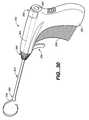
- This inventionalso includes a tissue locator element pusher assembly.
- This pusher assemblyincludes a housing having a lumen, a pusher slidably disposed in the housing lumen, and a delivery tube affixed to the housing having an optional sharpened distal tip and a tube lumen adapted for slidably receiving the pusher.
- the pushermay also have a pusher lumen for receiving at least a portion of a tissue locator element.
- An adjustable fastener for slidably fixing a portion of a tissue locator element to the pushermay also be included.
- a deployment fixturemay be detachably affixed to a distal end of the housing.
- the deployment fixturemay have at least one fixture lumen axially aligned with the pusher lumen and the delivery tube lumen.
- the pusher assemblymay also have a tissue locator element having proximal and distal portions that is at least partially disposable in the pusher lumen.
- a shoulderwhich may have at least one tab, may be disposed proximate the locator element distal portion. At least a portion of the tab may extend outside a plane defined by the locator element.
- This inventionis also a tissue locator element pusher assembly that includes a housing having a lumen, a pusher having a pusher lumen slidably disposed in the housing lumen, a tissue locator element at least partially disposed in the pusher lumen, and a delivery tube having an optional sharpened distal tip and affixed to the housing.
- the delivery tubehas a tube lumen adapted for slidably receiving the pusher and the tissue locator element.
- a deployment fixturemay be detachably affixed to a distal end of the housing.
- the deployment fixturemay have at least one fixture lumen axially aligned with the pusher lumen and the delivery tube lumen.
- This fixturemay also have a second fixture lumen disposed in a plane that is generally orthogonal to a plane in which the first fixture lumen is disposed.
- An adjustable fastener for slidably fixing a portion of a tissue locator element to the pushermay also be included.
- a shoulderwhich may have at least one tab, may be disposed proximate the locator element distal portion. At least a portion of the tab may extend outside a plane defined by the locator element.
- this inventionis a tissue locator element pusher assembly that includes a housing having a proximal end, a distal end, a central housing lumen, and at least one longitudinal slot in communication with the housing lumen, and a pusher slidably disposed in the housing lumen.
- the pusherhas a pusher lumen and an adjustable fastener for slidably fixing a portion of a tissue locator element to the pusher, a control lever affixed to the pusher and extending at least partially through the housing slot, and a tissue locator element at least partially disposed in the pusher lumen.
- the locator elementhas a shoulder disposed proximate a distal portion of the locator element.
- a delivery tube having a tube lumen adapted for slidably receiving the pusher and the locator elementmay be disposed on the distal end of the housing in communication with the housing lumen.
- this pusher assemblymay be configured so that axial movement of the control lever will result in a corresponding axial movement of the pusher and the locator element. In this way, the locator element will reversibly extend through an aperture in a distal end of the delivery tube.
- the assemblymay also be set up so that sufficient axial movement of the control lever may cause it to engage a detent disposed in the housing, prohibiting substantial further axial movement of the control lever.
- the engagement of the control lever and the detentmay be configured to correlate to an extension of the locator element shoulder through the delivery tube distal end aperture.
- the assemblymay further be set up so that just prior to engaging the detent, tactile or other feedback is provided to indicate that the engagement point is about to be reached.
- FIG. 1Adepicts a prior art wire localization technique.
- FIG. 1Bdepicts a further prior art wire localization technique.
- FIG. 2shows a tissue localization system according to the present invention.
- FIG. 3Ashows one embodiment of a tissue locating element according to the present invention.
- FIG. 3Bshows the tissue locating element of FIG. 3A together with a deployment tube and pusher assembly tube.
- FIG. 3Cshows another embodiment of a tissue locating element according to the present invention that is connected to an external energy source.
- FIG. 3Dis a cross-sectional view of the tissue locating element of FIG. 3 C.
- FIG. 3Eis yet another embodiment of a tissue locating element according to the present invention connected to a flexible wire or suture.
- FIGS. 3F-3Jshow various alternative shoulder configurations for a tissue locating element of the present invention.
- FIGS. 4A-4Eshow various views of a deployment tube and attached orientation element according to the present invention.
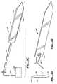
- FIGS. 5A-5Cshow various views of a tissue cutting element of the present invention disposed in a cannula for making an initial incision into tissue prior to deployment of the tissue locator element, complete with optional syringe and hub.
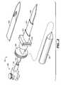
- FIG. 6shows an electrosurgical tool variation of a tissue cutting element of the present invention.
- FIGS. 7A-7C and 8show two embodiments of a tissue pusher assembly of the present invention.
- FIG. 9shows breast tissue containing a lesion and surrounding tissue volume placed between two compression paddles.
- FIG. 10shows the breast tissue and lesion of FIG. 9 penetrated by a blade extending distally from a cannula.
- FIG. 11shows the breast tissue and lesion of FIG. 9 with the blade removed and a trocar advanced into the tissue through the cannula to open up a pathway for accessing the lesion.
- FIG. 12shows the breast tissue and lesion of FIG. 9 with the trocar removed and a deployment tube and orientation element deployed in the cannula.
- FIG. 13shows the breast tissue and lesion of FIG. 9 with a locator element being advanced distally into the tissue by a pusher.
- FIG. 14shows the apparatus of FIG. 13 with the locator element advancing along a border of the tissue volume containing the lesion.
- FIG. 15shows the apparatus of FIG. 13 with the locator element continuing its advance along a border of the tissue volume containing the lesion to enclose a distal portion of the tissue volume.
- FIG. 16shows the apparatus of FIG. 13 with the locator element substantially deployed along a majority of a border of the tissue volume containing the lesion.
- FIG. 17shows the apparatus of FIG. 13 with an additional locator element partially deployed along a second path defining a border of the tissue volume containing the lesion at an angle to the first locator element.
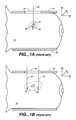
- FIG. 18is a top view of the apparatus of FIG. 17 with the second locator element fully deployed.
- FIG. 19is a perspective view of the apparatus of FIG. 17 with the second locator element fully deployed, demonstrating a polar deployment configuration.
- FIG. 20shows various paths the surgeon may take to excise the tissue volume substantially bounded but preferably not penetrated by the locator elements.
- FIGS. 21A-21Bshow a perspective and top view, respectively, of a locator element of the present invention deployed in a tangential configuration.
- FIGS. 22A-22Bshow a perspective and top view, respectively, of two locator elements of the present invention deployed in a tangential configuration.
- FIG. 23shows two locator elements of the present invention connected to a source of energy.
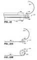
- FIGS. 23A-23Bshow an alternative use for a tangentially deployed locator element.
- FIGS. 24A-24Bshow a method for redeploying a tissue locating element into tissue for reexcision according to the present invention.
- FIGS. 25A-25D and 26 A- 26 Bshow two techniques for guiding the initial deployment of the locator element according to the present invention.
- FIGS. 27A-27Dshow a cold-forming process for shaping and deploying a locator element of the present invention with a deployment tube having a die.
- FIG. 28shows another embodiment of a cold-forming die according to the present invention.
- FIG. 29shows yet another embodiment of an adjustable cold-forming die according to the present invention having reverse and positive die cavity curves.
- FIG. 30is a perspective view of a further embodiment of a cold-forming locating element deployment device according to the present invention.
- FIGS. 31-33show rotatable tissue locating element variations according to the present invention.
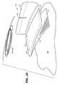
- FIG. 34is a perspective view of a tissue locating element proximal end pouch according to the present invention.
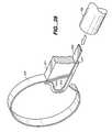
- FIG. 35is a perspective view of an offset fixture according to the present invention.
- the invention described hereinis appropriate for a wide range of applications for marking a specific volume of tissue for excision or other purposes.
- the description belowis largely in the context of marking a nonpalpable lesion in breast tissue and its subsequent excision, the invention is not so limited.
- the invention described hereinmay be used to mark tissue in a variety of locations in the body, such as the liver, the lungs, muscle tissue, or other tissue or organs where the advantages of the invention may be realized. It may also be used to mark a foreign object in tissue or body cavities as well, such as a bullet or the like. Accordingly, the invention and method for its use as described and claimed below is not limited to the marking and removal of lesions from breast tissue.
- FIGS. 1A and 1Bdepict the current state-of-the-art tissue location methodology and equipment for nonpalpable breast lesions.
- FIG. 1Adepicts a cross-section of breast tissue 10 having the lesion 20 to be marked for later removal disposed between two compression paddles 30 (shown in cross-section).
- a window 50lies in the upper paddle 30 for accessing the lesion, which is surrounded by tissue volume 22 .
- a localization wire 40is shown placed in the lesion.
- the wire 40 depicted hereinis “J”-shaped, and it may have a barb or hook on its distal tip to assist in anchoring the wire 40 in the breast tissue 10 .
- breast tissue 10contains a typically nonpalpable lesion 20 or suspect tissue that is targeted for removal.
- Lesion 20may contain precancerous or cancerous cells or it may contain one or more microcalcifications, which are often precursors to metastatic cell growth. Microcalcifications typically appear in clusters.
- a primary concernis that a large enough volume 22 of tissue is removed so that all of the suspect tissue is enclosed therein.
- the border or perimeter of this volume 22when properly sized, is colloquially called a “clean margin”. If the pathologist finds suspect tissue on or near the border of volume 22 , a “dirty margin” is present and additional tissue must be removed from the body along the previous tissue volume border until the pathologist is comfortable that all the suspect tissue has been removed. It is generally the goal, then, to remove the volume 22 of tissue completely containing within its borders the suspect tissue or lesion 20 .
- a radiologistperforms this procedure under local anesthesia, typically under x-ray guidance.
- the breast 10 containing the lesion 20 to be removedis placed between two compression paddles 30 to stabilize it for imaging and placement of wire 40 .
- Identification of the lesion 20 under this techniqueis based on measurements of the position of the lesion on two images of the breast taken from different angles (typically +15 degrees and ⁇ 15 degrees), called a stereo pair.
- the lesionis preferably centered below window 50 .
- a computermaps the breast tissue by generating a set of coordinates corresponding to the targeted lesion 20 and a portion of the tissue 10 surrounding the lesion.
- coordinatesare generated in three dimensions (x, y and z).
- the z coordinatetypically denotes to the depth of the lesion from the skin in a direction perpendicular to the surfaces of paddles 30 , while the x and y coordinates define a horizontal plane parallel to the plates 30 .
- This mapping procedurepinpoints the location of the lesion 20 as defined by the radiologist.
- the paddlesare adjusted so that lesion 20 is centered in the x-y plane below window 50 along a vertical (or z) axis.
- a small needleis next inserted into the tissue through window 50 in the upper compression plate 30 and moved towards the suspect tissue.
- This needle(not shown) acts as a deployment tube for localization wire 40 .
- wire 40will have a barbed or hooked distal end 60 or may take on a “J” shape as shown in FIG. 1 A.
- a follow-up x-rayis taken of the lesion with wire 40 in place, and the radiologist will mark the x-ray image to indicate the location of lesion 20 .
- the radiologistnext decompresses the tissue and transfers the patient to surgery for removal of lesion 20 . It should be clear from this discussion that it is difficult at best to accurately determine the proper depth (along the z-axis) to which the surgeon should cut to safely and satisfactorily excise the lesion.
- FIG. 1Bshows a less common technique in which a second wire 70 is used to mark the lesion 20 .
- the coordinates of the lesionare determined and the wires 40 and 70 are deployed on either side of the lesion, defining the margin along an x or y direction.
- the radiologistmarks the approximate lesion location on the x-ray as described before.
- the margins in the other two dimensionsmust again be approximated; the margins along the vertical or “z” axis are once again particularly difficult to determine with any degree of accuracy.
- Bracketingor “goalposting”
- goalpostingThe technique shown in FIG. 1B, called “bracketing” or “goalposting”, is often used in a second localization attempt when the radiologist was unsuccessful in marking the lesion in a prior attempt.
- FIG. 2shows one embodiment of a tissue localization system 100 that overcomes the deficiencies of current systems and methods.
- System 100typically comprises the following subsystems or components: a tissue locator element 200 , locator element deployment tube 300 , a driver tube or cannula 400 , locator element orientation element or clock wheel 500 , tissue cutting element or blade 600 , trocar 420 , and pusher assembly 700 .
- System 100is versatile. For instance, a stereotactic guide unit 80 may be connected to the driver tube 400 or some other component as shown in FIGS. 7-9. Guide unit 80 interfaces with a stereotactic x-ray system to guide system 100 to the proper coordinates as discussed above.
- System 100may be delivered via a variety of imaging modalities, including a mammography unit (either freehand or under stereotactic assistance), on a stereotactic table, under ultrasound or magnetic resonance imaging guidance, etc.
- System 100may alternatively or additionally be connected to a device such as a Fischer Table to provide a stable platform from which the system is used to mark tissue under x-ray guidance.
- An alternative driver positioning member or clevis 820may also be connected to a custom made vise or a commercially available driver, which in turn may be connected to a Fischer Table or other platform. This enables system 100 to be used with existing commercially available platforms and drivers, ensuring ease of use, low cost, and maximum versatility.
- blade 600which is slideably disposed in a lumen of driver tube or cannula 400 , is deployed through a distal end of cannula 400 into the breast tissue to the vicinity of the volume of tissue containing the lesion to be removed.
- Blade or cutting element 600may contain one or more tubular portions along its length, each having a lumen through which lubricant or an anesthetic may be administered as is discussed later.
- a proximal end of blade 600may be disposed in a lumen of tubular pusher element 730 , which is part of pusher assembly 700 .
- pusher assembly 700may also include a clamping ferrule or similar element 710 having a lumen for slideably receiving a proximal portion of blade 600 and, more importantly, locator element 200 .
- a thumbscrew or similar securing member 720is provided to fix a proximal section of the blade or locator element within the pusher assembly ferrule 710 .
- Pusher assembly 700may also be affixed to the aforementioned platforms or drivers in a variety of configurations; the arrangement described herein is merely exemplary.
- driver tube or cannula 400 together with trocar 420are inserted into the proximity of tissue 10 .
- Cannula 400may follow trocar 420 or may advance into the tissue simultaneously with trocar 420 .
- driver tube 400is advanced to the skin surface but does not penetrate (or just slightly penetrates) tissue 10 . This further opens up a passageway, or port, in the tissue for deployment of additional components of system 100 .
- the trocarAfter the trocar reaches the desired location near the tissue volume, it is proximally withdrawn from driver tube 400 , which is left in the tissue, and a preferably oval deployment or delivery tube 300 is inserted through the lumen of driver tube 400 so that its distal end is disposed in the region of the tissue volume to be excised.
- Locator element 200is preferably radiopaque, through the distal end of the tube 300 lumen to penetrate tissue and occupy the tissue volume boundary.
- Locator element 200is preferably designed to take on an arcuate or curvilinear shape when extended through the tube 300 distal end, such that as it penetrates tissue it follows a planar and preferably arcuate or curvilinear path to create a physical border around the majority of the perimeter of the targeted tissue volume, preferably without penetrating it.
- the locator element 200is designed to remain fixedly yet removably in place once deployed in tissue 10 as will be described later in greater detail.
- Delivery tube 300 , driver tube 400 , and any other component of system 100may then be removed, leaving only the locator element fixedly in place in the targeted tissue.
- the locator elementis long enough so that a reduced profile proximal end (or alternatively an attached suture or the like) extends proximally through the surface of the skin.
- the patientmay then either delay the excision procedure as desired or as dictated by the surgeon's schedule, or she may be transferred to surgery for excision of the marked volume.
- the surgeoncuts along the wire or the proximal portion of the locator element 200 , following it to the vicinity of the tissue volume.
- the surgeonexcises the tissue volume without invading the volume interior by cutting around the surface of the locator element opposite the locator element surface directly adjacent the tissue volume.
- the surgeonmay also access the locator element 200 by any number of approaches not necessarily along the proximal portion of element 200 , such as circumareolarly or via some other more direct or cosmetically acceptable approach as she sees fit.
- one or more additional locator elementsmay be deployed through delivery tube 300 into the tissue at an angle with respect to and about a longitudinal axis of the first locator element. This may be accomplished by the use of a clock wheel or orientation element 500 that may be rotated to orient the locator element or elements to a predetermined angle. Once oriented, the additional locator element or elements are deployed into the tissue in the same manner as the first locator element. These additional elements further define the same tissue volume along a different but similar arcuate path.
- each deployed locator element with respect to each othermay be arranged (e.g., at forty-five or ninety degrees) so that the spatial orientation and location of the tissue volume border occupied by the locator elements may be determined under x-ray or other visualization technique with greater accuracy.
- the remaining components of system 100may be removed and the tissue volume may be excised.
- FIGS. 3A-3Jdepict various embodiments of the locator element 200 .
- a particularly useful variation of element 200is shown in perspective as having a straight and flat configuration as it assumes when disposed in the confines of a deployment tube 300 lumen.
- a proximal portion 210 of locator element 200preferably having a smaller cross-sectional area than a distal portion 220 of locator element, is shown.
- Proximal portion 210transitions through a radius to distal portion 220 at shoulder 240 .
- the entire locator element 200is a single-piece article having no joints or the like.
- the proximal portion 210may be formed by laser or photoetching, traditional, electron-discharge or water-jet machining, cutting, or other techniques to reduce its cross-sectional area relative to distal portion 220 .
- proximal portion 210may be a separate article joined to distal portion 220 at shoulder 240 by any appropriate technique, such as soldering, welding, brazing, adhesives, or the like.
- proximal portion 210 and distal portion 220each have a similarly square or rectangular cross-sectional profile, but other profiles such as circular, elliptical, and irregular are also contemplated.
- the cross-sectional profile of proximal section 210need not be the same as the cross-sectional profile of distal portion 220 .
- FIG. 3Ashows only a width difference between proximal portion 210 and distal portion 220 , these portions may also differ in thickness.
- proximal portion 210The smaller cross-sectional area of proximal portion 210 compared to the distal portion 220 (as well as any possible differences in material properties when these portions are made from dissimilar materials) reduces the flexural modulus of proximal portion 210 relative to distal portion 220 . This affords greater flexibility or bendability to the device so to reduce the risk of locator element breakage, injury to others, and tissue trauma when proximal portion extends from the surface of the skin after locator element deployment but before excision.
- proximal portion 210is flexible enough to be freely and safely manipulated; for instance, proximal portion 210 may be taped or affixed to the patient's skin after deployment.
- Shoulder 240 at the transition of the proximal and distal portions of locator element 200is a particularly useful optional feature.
- Shoulder 240provides an engaging or abutting surface against which the radiologist or surgeon may advance the distal end of the pusher assembly 700 (see FIG. 3B) so to move locator element 200 out the distal end of deployment tube 300 and into the tissue. Furthermore, it provides a stop against the tissue to prevent locator element 200 from backing out accidentally. Enhancements to this “anchoring” feature of shoulder 240 are discussed below in conjunction with an embodiment of locator element 200 designed for use with a flexible wire or suture.
- Distal portion 220 of locator element 200is shown in FIGS. 3A and 3B as having a rectangular cross section and a distal end 230 that forms a blade or cutting surface. Alternatively or in addition, one or both of leading edge 250 or trailing edge 260 may form a blade or cutting surface.
- the particular shape of the distal end 230 and the cutting surface or surfacesare determined by the particular tissue in which the locator element 200 is designed to be placed and other clinical and practical parameters.
- the configuration of FIG. 3Ais but one of many possible to provide the most efficient advancing surface for moving through tissue.
- FIG. 3Cshows an alternative configuration in which locating element 200 is connected to source of energy 265 , preferably radio frequency (RF) energy, through lead 270 .
- RF source 265may be a BOVIE (Bovie Medical Corp., Melville, N.Y.) unit or the like to deliver high frequency current to locating element 200 .
- BOVIEBoovie Medical Corp., Melville, N.Y.
- RFmay be used alone to cut through tissue or may be used in conjunction with mechanical cutting means to assist in advancing the distal portion 220 of locating element 200 through tissue.
- Energy source 265may provide other electrical energy forms to locator element 200 , or it may also or instead be a source of mechanical, thermal, acoustic or other type of energy as may be desired.
- source 265When providing RF energy, source 265 not only aids in advancing the distal portion 220 into position around the tissue volume by cutting through the tissue, it may also be used to aid the surgeon in excising the tissue volume from the body of the patient, for instance, when the energized locator element 200 (or array of elements) is rotated through an angular displacement as will be discussed in greater detail.
- distal portion 220 of locator elementmay incorporate a leading edge 250 , a trailing edge 260 , or both, as shown in FIG. 3 C.
- These portions 250 and 260preferably but not necessarily will have a sharpened profile so to provide a cutting surface for displacing tissue and providing a focus for the high frequency energy.
- FIG. 3Dcross-section of a distal portion 220 of locator element 200 that may be used with RF energy.
- an insulative coating or layer 280covers the two opposing surfaces of the locator element 220 adjacent leading edge 250 and trailing edge 260 .
- Such insulation 280serves to electrically isolate the surfaces covered by the insulation and further focuses the RF energy on the leading and trailing edges.
- Insulation 280may comprise a ceramic or metallic oxide (such as alumina, tantalum oxide, titanium oxide, etc.), a biocompatible polymer or any other suitable biocompatible electrically insulating material.
- Insulation 280may be in the form of a coating that may be applied by well known deposition methods such as physical vapor deposition (including sputtering, evaporation, ion plating, ion beam-assisted deposition, ion implantation, etc.), diffusion (e.g., cementation), electrophoresis, anodizing, plating, chemical vapor deposition, pulsed laser deposition, painting, dipping, electroplating, laser surface processing, thermal spraying, etc. Insulation 280 may also be formed in situ via surface oxidation, etc. Insulation 280 may completely cover the opposing surfaces of distal portion 220 as shown in FIG.
- deposition methodssuch as physical vapor deposition (including sputtering, evaporation, ion plating, ion beam-assisted deposition, ion implantation, etc.), diffusion (e.g., cementation), electrophoresis, anodizing, plating, chemical vapor deposition, pulsed laser deposition, painting,
- insulation 280may cover only portions of these surfaces or additionally cover portions of leading edge 250 and trailing edge 260 .
- the amount of surface area covered by insulation 280 , as well as the insulation thickness, compositional profile, density, and other propertiesmay be tailored for the particular tissue and application in which the locating element 200 is designed to operate.
- insulative coating 280has a low coefficient of friction to ease the movement of locator element through tissue. It is even contemplated that the locator element be coated with a noninsulative but low-friction coating, whether the device is used with RF or other energy or not, simply to achieve this goal.
- FIG. 3Eshows another variation of locating element 200 in which a flexible wire, cable, suture or the like 290 is attached to locating element via eyelet 292 .
- the overall length of locating element 200may be considerably shorter than other variations, as the cable 290 may be viewed as taking the place of locator element proximal section 210 .
- a suture 290is even more suitable than the proximal portion shown in FIG. 3A for presenting a flexible, safe, and effective “lead” that may extend out through the breast surface after the locator element has been placed in the tissue.
- Threading wire 290 through eyelet 292is but one of a wide variety of ways to connect wire 290 to locator element 200 . More than one eyelet may be present, for example, if it is desired to attach multiple sutures or other elements to locating element 200 ; alternatively, multiple sutures or other elements may be attached to locating element via a single eyelet 292 . In addition, eyelet 292 or an equivalent attachment junction may be disposed distally of proximal end of locating element 200 , either centrally or on one side thereof.
- FIGS. 3F-3Ishow an anchoring feature on a locator element 200 having eyelet 292 ; the variation of FIG. 3J shows an anchoring feature on a locator element without an eyelet; however, each of these variations may be used interchangeably both with and without eyelets.
- FIG. 3Fcomprises a locator element 200 having a serpentine edge 222 on its proximal end.
- Two recessed apertures 244create three tabs 246 that may be substantially aligned with the plane defined by locator element 200 as shown, or that may be oriented outside this plane to enhance the anchoring effect.
- the outer two tabsmay be disposed at positive and negative angles, respectively, with respect to this plane as shown in FIG. 3 G.
- the increased surface area of the locator element 200 proximal end presented by this serpentine design and the portions of the surface 222 oriented other than 90 degrees with respect to the locator element planeincreases frictional resistance with tissue, enhancing the anchoring effect.
- FIG. 3 GAn alternative double flange configuration for anchoring locator element 200 is shown in FIG. 3 G.
- tabs 246are similar to the tabs in the FIG. 3F embodiment except that they are deflected in opposite directions with respect to central tab 246 , which is generally aligned with the locator element plane.
- the tabsare longer, presenting even more locator element proximal end surface area for increased frictional resistance and anchoring in tissue.
- FIG. 3Hdepicts yet another variation.
- a single tab 246is cut out of the proximal end of locator element 200 distal to eyelet 292 .
- This variationdepicts tab 246 as being disposed at an angle with respect to the locator element 200 plane so that when the locator element curves in tissue it faces outward as shown in FIG. 3 H.
- FIG. 3Ia dual-tab configuration is shown on a locator element 200 with eyelet 292 .
- FIG. 3Jdepicts a variation in which locator element contains a proximal portion 210 as previously described; note the absence of any eyelet in this embodiment.
- the tabs or flangesare designed to facilitate forward (distal) movement of the locator element into tissue 10 as described herein, while generally resisting movement in the lateral or reverse (proximal) directions.
- the tabs or flangespreferably will not engage tissue to resist reverse movement until the locator element is deployed to its desired permanent position. This ensures the reversibility of the locator element deployment up until the point at which the tabs or flanges deploy into tissue as well.
- Other featuresmay be used to variously tailor the effectiveness of the tabs or flanges.
- the depth of the tab cutsmay be relatively shallow or deep, the angle of the tabs 246 relative to the locator element plane may be relatively small or large, etc.
- locator element 200comprises a shape memory material, the tabs or flanges 246 may be thermally activated to assume a relatively low or high angle profile with respect to axis 248 to tailor the anchoring effect as needed.
- each of the anchoring features discussed hereinis exemplary of a large number of designs and configurations possible within the scope of this variation.
- the number of tabs, angular orientation of the flanges, and depth of cutmay vary significantly from those examples discussed herein.
- Locator element 200is designed to assume a generally arcuate or curvilinear shape when unconstrained or when deployed in tissue.
- locator element 200comprise a material having a shape memory, such as spring steel, stainless steel, nickel-titanium alloy such as nitinol, a shape memory polymer, or other such materials.
- locator element 200be nickel-titanium, although less desirable alloys (from a toxicity standpoint) that exhibit shape memory characteristics, such as copper-zinc-aluminum, copper-aluminum-nickel, copper-zinc-silicon, copper-zinc-lead, gold-cadmium, and nickel-cadmium, are contemplated as well.
- alloysmay be coated or covered with a material to enhance biocompatibility.
- superelastic materialsi.e. temperature-independent
- temperature-dependent one- and two-way shape memory materialsare contemplated for locator element 200 .
- Such materials and their behaviorare described in U.S. Pat. Nos. 3,174,851, 3,351,463, 3,753,700, 4,665,906, 5,067,957, and 5,190,546; the entirety of each is hereby incorporated by reference.
- locator element 200when unconstrained or constrained only by tissue may be designed into the element for a variety of tailored applications as is well known in the art. It is within the scope of this invention, for instance, to supply a kit to the radiologist having a variety of locator elements with differing loop diameters and perhaps differing shapes from which to choose. A template or similar instrument that may be held up to an x-ray of the tissue containing the lesion 20 and surrounding tissue volume 22 may be provided as well. This would allow the radiologist to accurately select the proper locator element for deployment into the particular tissue of interest.
- Locator elementmay be mechanically straightened to assume a first generally linear or flat configuration as it is inserted into deployment or delivery tube 300 or equivalent constraining member. As the distal end of the locator element 200 is deployed beyond the distal end of delivery tube 300 into the tissue of interest by pusher assembly 700 , locator element 200 naturally assumes a second, substantially arcuate or curvilinear profile discussed above as it penetrates tissue and defines a tissue border along a path. The tissue border defines a tissue volume containing the targeted lesion that is to be excised. Preferably, locator element 200 does not penetrate the tissue volume as it is deployed.
- This shape transformation described aboveis preferably entirely temperature-independent; that is, it may take place at a single temperature simply upon removing the physical or mechanical constraint of tube 300 or the like as it deploys into tissue or a cavity.
- materials exhibiting temperature-dependent transformation propertiese.g., those that can be engineered to transform from a flat, planar shape into an arcuate or curvilinear shape upon reaching a temperature threshold (such as body temperature), may be used for the locator element as well.
- Locator elementmay also assume more complex shapes having more than a single curve or even curves that change direction.
- a given locator element 200will often assume different deployed shapes depending upon the medium into which it is deployed. Further, we have found that these differences are predictable. For instance, a nitinol locator element deployed into ambient air may take on a circular deployed shape having a diameter of one inch. However, when that same locator element is deployed into breast tissue, its diameter increases to a somewhat larger size; e.g., 1.125 inches. Although this phenomenon is not completely understood, we believe it is influenced by the constraining effect of the tissue surrounding the locator element and the increased force required to advance the same into the tissue.
- Such a phenomenonmay be affected by a number of parameters, including the medium into which the locator element is deployed (e.g., breast tissue, lung tissue, liquid, air, etc.), the material comprising the locator element (e.g., nitinol, stainless steel, etc.), the intended deployed shape of the locator element (e.g., circular, elliptical, serpentine, etc.), the dimensions of the locator element, temperature, the presence of additional locator elements in the tissue, polar vs. tangential deployment, etc.
- the medium into which the locator element is deployede.g., breast tissue, lung tissue, liquid, air, etc.
- the material comprising the locator elemente.g., nitinol, stainless steel, etc.
- the intended deployed shape of the locator elemente.g., circular, elliptical, serpentine, etc.
- the dimensions of the locator elementtemperature
- the presence of additional locator elements in the tissuepolar vs. tangential deployment
- a physicianmay desire that a given nitinol locator element deployed in tangential fashion into breast tissue take on an elliptical shape having major and minor axes of 1.25 inches and 1 inch, respectively.
- Knowledge of such an element's deployment shape in air under a given set of conditionsallows us to generate design information to aid the engineer in producing a locator element having these desired dimensions when deployed in breast tissue.
- locator element 200be at least partially radiopaque so that it may be readily viewed under x-ray energy. This aids the radiologist in placing locator element 200 in the desired tissue position as well as allowing for verification of its location and orientation.
- Locator elementmay be radiopaque by virtue of its inherent material properties; i.e., nitinol exhibits both a shape memory effect and some radiopacity as well, making it a suitable material for use in the locator element.
- the radiopacity of locator element 200may be enhanced by adding a variety of components comprising materials exhibiting greater radiopacity, such as bands or elements made from platinum, palladium, tungsten, gold, silver, etc., that may be bonded or otherwise affixed to locator element 200 in predetermined locations (such as, e.g., along the leading edge 250 and trailing edge 260 or on the distal end of locator element 200 ). If locator element distal section 200 is insulated, such insulation may be radiopaque as well. For instance, polytetrafluoroethylene doped with barium sulfate or some other appropriate radiopaque material is suitable for this purpose.
- the distal portion 220 of locator element 200preferably comprises a ribbon having a rectangular cross section. Such a shape provides a surface against which the surgeon may cut when excising the tissue volume contained by the locator element.
- the orientation of the locator elementmay be readily determined under x-ray visualization depending upon which surface (i.e. a leading or trailing edge as opposed to a wider surface) is presented to the viewer. Even if the deployed locator element 200 occupies multiple planes in the tissue with respect to the x-ray or ultrasound source, such information should be readily visible due to the asymmetric shape of ribbon locator element 200 .
- a ribbon shapealso most readily facilitates movement around tissue volume 22 as the path is defined, particularly in the distalmost portion of the path or border 24 .
- distal portion 220be a ribbon as described above, it is not so limited.
- the distal portion 220may have a circular, elliptical, oval, or irregular cross-sectional shape.
- Various rectangular cross-sectional shapesranging from square to those having higher cross-sectional aspect ratios (i.e., a ribbon) are contemplated as well.
- distal portion 220 of locator element 200may be between about 1.0 mm and 7.0 mm wide and between about 0.2 mm and 1.0 mm thick; we prefer it to be between about 2.0 mm and 5.0 mm wide and about 0.5 mm and 0.8 mm thick.
- Other cross-sectional shapespreferably are on the order of the same dimensions as those recited above.
- a ribbon width of about 1.5 mm (about 0.060 inch)is particularly desirable. This width provides the optimum balance of properties (e.g., manipulability, anchorability, and palpability) during and after deployment around tissue volume 22 .
- a shoulder portion 240may transition from the ribbon portion having a rectangular cross section to a proximal portion 210 having a generally square or rectangular cross section with a thickness preferably the same as that of distal portion 220 and a width on the order of approximately 30 percent to approximately 80 percent of the width of distal portion 220 .
- the particular ratio of the widths of proximal portion 210 to distal portion 220will depend on the design constraints associated with the particular application for which system 100 is chosen.
- the cross-sectional shape of proximal portion 210does not have to be the same as that of distal portion 220 .
- locator element 200and its operation in conjunction with the other components of system 100 are discussed below in greater detail.
- FIGS. 4A-4Eoval deployment or delivery tube 300 is shown with orientation element or clock wheel 500 .
- Deployment tube 300is the primary device through which locator element 200 is delivered to the targeted tissue volume perimeter.
- the particular design elements of tubeare not critical to the operation of the invention; as long as it effectively aids in delivering locator element 200 to the proper location, deviations from the features described herein and shown in the figures are possible.
- Delivery tube 300preferably has a lumen 310 that has a generally oval cross-sectional shape to accommodate the rectangular cross-sectional shape of locator element 200 and to present a lower profile when penetrating tissue. This ensures proper deployment of locator element 200 in the desired position and angular orientation.
- delivery tube lumen 310may assume a variety of other cross sectional shapes, including circular, rectangular, irregular, etc. In any event, we particularly prefer that delivery tube lumen 310 have cross-sectional dimensions sized so that the locator element 200 may freely axially or slideably move therein; in addition, free or limited rotational movement of locator element 200 therein is also contemplated.
- tube 300be a stainless steel hypotube or the like, although it may comprise a polymer, nickel-titanium, a composite material, or other metals such as platinum, tungsten, cobalt, titanium and their alloys.
- a proximal section 310 of tube 300terminates at interface 330 with an orientation element or clock wheel 500 as shown in FIGS. 4A and 4B.
- Interface 330may be a simple recessed interference fit or other type of joint between the proximal end 310 of tube 300 and wheel 500 .
- Interface 330need not be permanent; proximal section 310 may be removably inserted into orientation element 500 , locked in place, and removed so that another tube 300 (perhaps with a different cross-sectional shape) fits therein.
- orientation element 500 and delivery tube 300may be integrally formed as a single unit so that interface 330 is simply a transition between the two.
- orientation element 500has a flange 510 bounded by serrations 520 to facilitate gripping and rotation as described below.
- flange 510has a straight or flat edge 530 to indicate to the radiologist the particular angular orientation of tube 300 selected.
- system 100may be configured so that when the flat section 530 is aligned with stereotactic guide unit 80 (see FIGS. 7 - 9 ), the radiologist knows that the major axis of oval deployment tube 300 , and in turn the major axis along the width of locator element 200 , is aligned with the particular axis indicated by guide unit 80 .
- flange 510may have an additional flat surface parallel to surface 530 on the opposite side of flange 510 .
- wheel 500may contain notches, raised sections, alphanumeric markings, electronic indicators (audible, visual, etc.), or combinations of these and other features to indicate the angular orientation of element 500 with respect to the tissue coordinate system. Any device that indicates to the user the spatial orientation of tube 300 and in turn locator element 200 is within the scope of this present invention.
- Orientation element 500may be metallic or polymeric as dictated by design and functional considerations.
- FIGS. 4D-4EA useful variation of deployment tube 300 that may be used in any of the embodiments disclosed herein is shown in FIGS. 4D-4E.
- a sharpened distal tip 322facilitates safe and reliable entry into tissue during the locator element deployment procedure. It may be used to penetrate tissue in advance of deploying the locator element, or it may be used in conjunction with the cutting element 600 and cannula or driver tube 400 described below.
- Distal facets 324 and 326are seen as tapering to a distalmost point 328 .
- Distal facets 324 and 326preferably comprise sharpened leading edges 325 and 327 for more readily cutting through tissue.
- Proximal facets 332 and 334 on the upper portion of the tube distal tip 322may also be sharpened to formed sharpened trailing edges 336 and 337 as shown.
- a particularly useful way to achieve the distal tip 322 of FIGS. 4D and 4Eis by fabricating deployment tube 300 , or at least the distal portion 322 , of stainless steel hypodermic needle, hypotube, or the like.
- a portion of the hypodermic needle(which typically has a round cross-section) is cut off to form an acute angle, preferably between about ten and forty-five degrees, and even more preferably between about twelve and eighteen degrees, between the trailing edges 332 and 334 and a central axis of the deployment tube.
- the leading edgesare faceted into curved surfaces terminating at a sharpened tip 328 . Any of the edges are sharpened as desired, and the entire tube is pressed so its cross-section becomes generally oval or elliptical in shape as seen in FIG. 4 E.
- tip 322 shown in FIGS. 4D and 4Eis not only useful for cutting through tissue but also for dilating tissue prior to the advancement of locator element 200 .
- curvature of faceted leading edges 324 and 326helps to facilitate cutting through and dilating tissue as described herein.
- cutting element or blade 600is shown partially slideably disposed in a lumen of driver tube 400 .
- blade 600is designed for deployment through driver tube 400 to initially penetrate tissue and create an access pathway through which delivery tube 300 and eventually one or more locator elements 200 may be deployed.
- Driver tube or cannula 400is preferably oval in cross-section to present a low profile configuration (as shown in FIG. 2 ), although it may have a more round cross-section (as shown in FIGS. 5A and 5C) or a cross-section that conforms to the cross-sectional profile of blade 600 , especially the blade distal region 620 as discussed below.
- any cross-sectional shape for cannula 400 suitable for deploying cutting element 600 , deployment tube 300 , and locator element 200is within the scope of the invention.
- driver tube 400be sized so that the deployment tube 300 may freely axially or slideably move therein; in addition, free or limited rotational movement of delivery tube 300 therein is also contemplated.
- cannula 400be a stainless steel hypotube or the like, although it may comprise a polymer, nickel-titanium, a composite material, or other metals such as platinum, tungsten, cobalt, titanium and their alloys.
- Blade 600may take on a wide variety of shapes, cutting surface configurations, and features depending upon the particular design and functional constraints for the application chosen.
- FIGS. 5A-5Cshow a particularly useful blade design for making an initial incision into breast tissue to create an access passageway for deploying one or more locator elements as described herein.
- Cutting element 600has a proximal region 610 terminating at proximal end 630 and a distal region 620 terminating at a distal end 640 .
- distal region 620contains blade edges 650 and the distal end 680 of tubular members or lumen 660 disposed along the length of blade 600 .
- Tubular member 660may be considered an integral part of blade 600 .
- FIG. 5Ashows one of two tubular members 660 that are better seen in cross-section of FIG. 5 B. As one moves proximally along blade 600 , this dual-lumen cross-sectional profile gradually transitions into one having a single lumen as is shown in FIG. 5 C.
- Cutting element 600terminates, in this particular embodiment, in a hub 690 which attaches to an optional syringe 692 .
- Blade edges 650are seen disposed along a single axis and joining at a single point near the distal end of blade 600 .
- Blade edges 650may take on a number of different configurations. They may be serrated, for example, and they may be capable of using electrical, acoustic, mechanical, or thermal energy as described herein and in greater detail below. Although the particular tip features and configuration of blade edges 650 may vary considerably and be within the scope of the invention, we have found the configuration of FIGS. 5A-5C to be particularly useful for cutting through breast tissue.
- Cutting element 600is designed to alleviate some of the difficulties associated with penetrating tissue by providing a port or lumen 660 through which various agents may be administered to the patient, preferably but not necessarily while the blade is cutting through tissue.
- an anesthetic agentsuch as lidocaine gel or liquid or the like may be selectively administered to tissue through the distal end 680 of tubular member lumen 660 via a syringe 692 connected to the blade 600 at hub 690 .
- a lubricantsuch as K-Y jelly (Johnson & Johnson, New Brunswick, N.J.) or liquid, a water-based lubricant, or the like, may be administered during the cutting process to reduce the coefficient of friction between the blade edges 650 and tissue as the blade 600 cuts through the tissue.
- Other substancesmay be disposed through tubular member 660 as required, such as anti-thrombolytic agents, hormones, chemotherapeutic drugs, anti-scarring agents, etc. These and other substances may be administered manually by the radiologist during the procedure intermittently or continuously, or they may be automatically dispensed by any number of electronic, mechanical, or electromechanical means.
- FIGS. 5A-5Cshow only two tubular members 660 , the invention is not so limited. Any number of tubular members may be used with this invention, from one to six or more, depending upon the needs of the patient and the objective of the procedure in which blade 600 is being used.
- Blade 600 and tubular member 660may be metallic, polymeric, a composite material, or a combination of metals, polymers, and their alloys as described herein. Particularly useful is stainless steel.
- the various components of this variation of cutting element or blade 600may be integrally formed as a single element, or they may be assembled via any number of a suitable joining techniques, such as welding, brazing, soldering, adhesives, or the like.
- blade edges 650be hardened stainless steel so to provide a keener cutting surface that does not dull with use.
- a valve and seal system as is well known in the artmay accompany hub 690 to facilitate selective administration of the desired agent.
- Tubular member 660is optional. However, its low profile and functional utility for both patient and doctor make it a clearly useful feature that effectively complements system 100 .
- blade 602comprises a standard electrosurgical pencil unit as is well known to those of skill in the art. Units and accessories such as those sold by Aaron Medical Industries, Inc. (St. Moscow, Fla.) are suitable for this purpose.
- Electrocautery pencil base unit 604 having a standard control switch 606is attached to a power cord 608 and three-prong connector 609 .
- a power cord 608 and three-prong connector 609We find it useful to employ an off-the-shelf extended tip 612 having a standard 0.24 cm diameter proximal end 616 and a shaft 614 with the appropriate length to reach the tissue 10 as described herein.
- the shaft lengthbe between about 2 cm and 15 cm; more preferably between about 4 cm and 12 cm.
- An active electrode 618is disposed on a distal end of tip 612 for delivering cutting and cauterizing energy to tissue.
- An alternative electrode 622 having a more tapered profilemay be used to more readily facilitate penetration into tissue 10 and create the needed passageway for deploying locator element 200 .
- an insulative coatingmay again be employed on the blade electrode 618 or 622 .
- FIGS. 7A-7C and 8two tissue locator element pusher assembly variations of the present invention are shown. These variations, which are but two of many possible, achieve the objectives of providing a simple, safe, repeatable and reliable locator element deployment into the tissue of interest.
- FIGS. 7A-7Cshow a pusher assembly 700 comprising a housing 702 attached to deployment or delivery tube 300 and slidably containing at least a portion of a pusher tube 730 and locator element 200 therein.
- a ferrule 710 having two adjustable fasteners 720 and a central channel or lumen 712 for receiving the proximal end of locator elementis also shown.
- Housing 702preferably is comprised of a structural polymeric material, a metal or metallic alloy, or any combination thereof. Although housing 702 is shown in FIG. 7A as having an elongated tubular shape, it not need be so. Housing 702 , for instance, may have a rectangular, oval, asymmetric, etc., cross section.
- Housing 702is preferably at least partially hollow such that it contains a central housing lumen 708 throughout at least a portion of its length from housing proximal end 704 to housing distal end 706 .
- Lumen 708should be large enough to slidably accommodate pusher 730 and ferrule 710 as will be described in greater detail later.
- housing lumen 708In communication with housing lumen 708 is at least one, and preferably two, longitudinal slots 709 as shown in FIGS. 7A and 7B. Slot 709 extends for at least a portion of the length of housing 702 , and we prefer that it extend through a majority of the housing 702 (although it not need do so). Longitudinal slot or slots 709 form channels for accommodating adjustable fasteners 720 or a control lever; these are optionally attached to ferrule 710 and/or pusher 730 for axially advancing and retracting a slidably disposable pusher 730 and locator element 200 through housing lumen 708 .
- FIGS. 7A and 7Bmay comprise a delivery or deployment tube 300 as described elsewhere herein.
- Tube 300is preferably oval in cross section for accommodating a locator element 200 through a central lumen 310 .
- Delivery tube 300is in communication with the housing lumen 708 so that the tube lumen 310 may at least partially receive pusher 730 and locator element 200 .
- Axial movement of pusher 730 and locator element 200 through this lumen 310results in the deployment and retraction of locator element 200 through an aperture in tube distal end 368 .
- pusher tube 730is shown in FIGS. 7B-7C as comprising a main portion 732 , preferably but not necessarily having a circular or square cross section, and a tube lumen 712 that slidably accommodates the proximal portion 210 of tissue locator element 200 .
- FIG. 7 CA perspective view of the transition between tube main portion 732 and ferrule 710 is seen in the view of FIG. 7 C. Note tube central lumen 712 and tube proximal end 714 disposed on the proximal end of ferrule 710 for accommodating the locator element proximal portion 210 , including any portion thereof that extends proximal of ferrule 710 .
- Adjustable fasteners 720 in the form of two thumbscrewsmay be screwed into apertures in ferrule 710 .
- the usermay slidably and adjustably fix the proximal portion 210 to the pusher between fasteners 720 so that the locator element 200 cannot axially move within pusher lumen 712 .
- Thisallows advancement of both pusher tube 730 and locator element 200 together as a single unit.
- the thumbscrews of FIGS. 7A-7Care but one of a number of equivalent fasteners 720 that may be used to adjustably fasten or fix locator element 200 to pusher tube 730 .
- a locator element 200is shown in FIG. 7B is at least partially disposable in lumen 712 of pusher tube 730 such that its proximal portion 210 extends out of tube proximal end 714 , through tube distal aperture 734 .
- Locator element distal portion 220is seen extending out the tube distal aperture 734 and assuming a preformed shape for marking tissue lesions.
- Note shoulder 240disposed proximate the locator element distal portion 220 , where it transitions to locator element proximal portion 210 .
- This shoulder 240serves as an abutting surface against which the distal end of pusher tube main portion 732 may rest. Shoulder 240 also serves a number of purposes in tissue (with optional tab features) as described below in greater detail.
- the present pusher assemblymay be used as described herein or in a modified form (for instance, with an alternative fastener 720 ) to accomplish the purposes of the invention.
- a locator elementis loaded into pusher tube 730 such that its proximal portion 210 is loaded to the desired position. Abutting feature of shoulder 240 to the distal end of tube main portion 732 may be used as a reference to aid in determining the relative position of the locator element 200 when it is deploying in tissue.
- the assembly of pusher tube 730 and locator element 200is then loaded into the housing 702 through housing proximal end 704 ; adjustable fastener or fasteners 720 may then be inserted through housing slot or slots 709 and into ferrule 710 to affix locator element proximal portion 210 within pusher tube 730 .
- adjustable fastener or fasteners 720may then be inserted through housing slot or slots 709 and into ferrule 710 to affix locator element proximal portion 210 within pusher tube 730 .
- thisis but one of a number of ways to assemble the pusher assembly 700 .
- the useradvances the pusher tube 730 and locator element 200 via adjustable fasteners 720 (thus using them as handles) to axially advance them through the housing lumen 708 and deployment tube lumen 310 so that the locator element distal portion 220 extends out of tube distal aperture 368 as shown in FIG. 7 A.
- the usermay retract pusher tube 730 and locator element 200 as necessary so that distal portion 220 can be repositioned in tissue or prior to placement in the tissue.
- a particularly useful feature of pusher assembly 700is its versatility.
- a deployment fixturesuch as offset fixture 900 (described below) may be detachably affixed to housing 702 , preferably but not necessarily at housing distal end 706 , and either with or without deployment tube 300 .
- the offset fixture of FIG. 35may comprise two oval deployment tubes extending from fixture body 940 ; these may be part of the fixture or they may be part of pusher assembly 700 and extending through fixture body 940 as desired.
- Housing 702may be affixed, preferably detachably, to a deployment fixture by means known to those of skill in the art. For instance, any number of secure and easily detachable joints or connectors, such as quick disconnect couplers sold by Colder Products Corp. (St. Paul, Minn.), are particularly effective.
- the deployment fixtureWhen connected to the pusher assembly 700 , the deployment fixture preferably comprises at least one fixture lumen that is axially aligned with the pusher lumen 712 and the delivery tube lumen 310 . This ensures that advancement of the pusher tube 730 in housing 702 will result in the intended reversible deployment of the locator element 200 into the targeted tissue region.
- FIG. 8shows an alternative variation of pusher assembly housing 702 .
- This housing 702has largely the same features as the embodiment of FIGS. 7A-7C and is shown without optional deployment tube 300 .
- housing body 702has a proximal end 704 , a distal end 706 , a housing lumen 708 and at least one longitudinal slot 709 disposed along one side of the housing body.
- a control lever 716is shown partially disposed in slot 709 and extending outside housing 709 for access by a user.
- Lever 716is affixed to a pusher tube (not shown) disposed in housing lumen 708 as described above.
- Lever 716may be adjustably attached to pusher tube 730 so that it may aid in securing the proximal portion 210 of locator element 200 as described in conjunction with FIGS. 7A-7C.
- Lever 716may also have a lever tab 718 .
- a detent or notched mechanism 719 disposed near the distal end 706 of the FIG. 8 housing 702is configured to cooperate with control lever 716 or the control lever tab 718 as the control lever (and attached pusher tube/locator element) is moved distally by a user along slot 709 .
- control lever 716 and pusher tube/locator elementmay be moved in either the proximal or distal directions along slot 709 in the housing lumen 708 to advance the locator element into tissue and to retract the locator element if the user so desires.
- assembly 700be configured so that as the user axially advances lever 716 distally to the point in which control lever 716 or lever tab 718 engages detent or notched mechanism 719 , lever 716 is prohibited from moving proximally, thus “locking” pusher tube 730 and locator element 200 in place relative to housing 702 .
- the assembly of FIG. 8may be configured so that when this locking mechanism is activated during use, the shoulder portion 240 of locator element 200 has penetrated into tissue a distance sufficient to anchor locator element 200 in the tissue, largely fixing the locator element 200 in place.
- lever tab 718 and detent 719provide not only a feedback mechanism for the user to indicate that the locator element is now “locked” into place in the tissue, it also provides a safety function to prohibit the user from forcing the locator element 200 proximally once the shoulder 240 has engaged tissue (an action that may damage the tissue). This allows the user to safely and reversibly adjust the position of the locator element in the tissue as necessary until the desired alignment and deployment configuration is achieved, at which point the final configuration may be locked in.
- the detent 719may be biased to provide resistance upon initial contact with the lever tab 718 so that the user senses the distalmost limit of reversible axial motion in slot 709 immediately prior to engagement of detent 719 .
- Other mechanical or electromechanical feedback mechanismsincluding visual (e.g., colored lights) or audible (e.g., alarms), may be used to indicate this limit of reversible axial motion as well as the irreversible anchoring of the locator element 200 into tissue as described.
- FIG. 8 deviceis shown without a deployment tube 300 .
- a deployment fixturemay detachably affix to the FIG. 8 housing 702 , preferably at the distal end 709 .
- the pusher tube and locator elementmay be reversibly moved within the housing lumen 708 to extend through an aperture 721 of the housing lumen 708 and into an aligned deployment fixture lumen.
- Other features as described above with respect to FIGS. 7A-7Cmay also be used in the FIG. 8 assembly as desired.
- FIGS. 9-20show, in detailed fashion, a method for using system 100 to mark a volume of tissue for eventual removal or excision from the breast, preferably without penetrating or otherwise violating the interior of the tissue volume.
- a particularly useful technique in which one or more locator elements are deployed in a “polar” fashionis described below.
- this methodis described in the context of removing a nonpalpable lesion from the breast, it may be followed for marking and excising any tissue mass or foreign object from the body.
- a methodfor defining the border of a tissue volume to be excised from a patient. This is accomplished by deploying at least one locating element into breast tissue so that it follows a continuous path around the selected tissue volume, thereby containing the target tissue region. Later excision of the so-marked tissue volume by a surgeon is also described.
- the patientis typically first prepared for the marking procedure by placing the breast tissue 10 between two compression paddles 30 on a platform such as a Fischer Table.
- the tissue volume 22 containing the suspect lesion 20is next mapped under x-ray guidance and a three-dimensional coordinate system or grid is assigned to the tissue of interest.
- a three-dimensional coordinate system or gridis assigned to the tissue of interest.
- the entire breast tissue 10 between plates 30is mapped on a three-dimensional coordinate system.
- “x” and “y” coordinates in FIG. 9are associated with a tissue location along axes in a horizontal plane parallel to paddles 30 .
- the “z” coordinatedescribes a tissue location in a vertical or depth plane perpendicular to each of the x and y axes.
- FIG. 10shows portions of system 100 after lesion 20 and targeted tissue volume 22 have been identified, centered below window 50 , mapped in three-dimensional coordinates, and driver tube 400 (shown in cutaway cross-section) with attached stereotactic guide unit 80 is centered over window 50 .
- Blade 600is disposed in a lumen of driver tube 400 .
- a longitudinal axis of cannula 400is generally aligned with a vertical or z-axis of the mapped tissue such that the cannula lumen is centered over tissue lesion 20 .
- Thisconfigures system 100 so that locator element 200 deploys into the tissue 10 along this axis; hence the term “polar deployment”.
- Blade 600is then deployed distally through the cannula 400 lumen so that it exits the cannula distal end and penetrates through tissue 10 to the targeted tissue volume 22 to be excised.
- the radiologistmay manually advance blade 600 into tissue 10 , preferably with the assistance of x-ray, ultrasound, magnetic resonance, or other method.
- Such a techniquemay be preferable, especially under difficult or delicate conditions where caution and control are at a premium.
- blade 602utilizes energy (such as RF energy) to assist the user in penetrating through tissue 10 and to create an access port for locator element 200 .
- energysuch as RF energy
- This blade 602is deployed into the cannula lumen in the same manner as blade 600 so that it exits the cannula distal end into the tissue 10 that is centered below window 50 .
- Control switch 606allows the user to apply cutting or coagulating energy, alone or in combination, to penetrate through this targeted tissue 10 to reach tissue volume 22 .
- blade 600may be advanced automatically, such as via a spring-loaded or similar biopsy driver mechanism as is well known to those of skill in the art.
- system 100may be adapted to interface with any number of commercial biopsy driver systems through, for instance, an optional driver positioning or interface member.
- Pusher assembly 700may also be used to advance blade 600 into tissue 10 .
- cutting element 600will penetrate tissue 10 so that its distal end 640 just reaches the vicinity of the surface or border of tissue volume 22 .
- blade distal end 640will reach the border of tissue volume 22 along the z-axis as described above, while other deployment schemes may dictate deployment at other locations along or near the border of tissue volume 22 .
- the blade 600 distal tip 640does not penetrate into the tissue volume 22 . If the tissue volume 22 is inadvertently or intentionally penetrated, however, care should be taken to preserve the integrity of tissue volume 22 and avoid penetrating further into lesion 20 .
- cutting element 600is equipped with one or more tubular members as previously described, lubricating agents, anesthetics such as lidocaine, or any number of other appropriate pharmaceutical agents may be administered through the tubular member lumen 660 so that they are deployed into the tissue through tube distal end 680 .
- lubricating agentssuch as lidocaine
- anestheticssuch as lidocaine
- any number of other appropriate pharmaceutical agentsmay be administered through the tubular member lumen 660 so that they are deployed into the tissue through tube distal end 680 .
- agentsare administered simultaneously as the blade 600 is advanced into tissue 10 ; however, they may be administered before or after the pathway is created.
- one or more sensors, fiber optics, electrocautery electrodes (to control bleeding during cutting), or other devicesmay be deployed through lumen 660 .
- FIG. 11shows system 100 after blade 600 has been proximally withdrawn from tissue 10 and cannula 400 , and a conventional trocar 420 has been deployed into the lumen of cannula 400 until its distal end 430 extends distally of the distal end of cannula 400 .
- Trocar 420 and cannula 400may then be advanced as a unit, or with the trocar leading in sequential deployment, into the tissue 10 through the pathway created by blade 600 to further define and enlarge it.
- trocar 420is advanced just to the edge or border of tissue volume 22 as previously described for deployment of cutting element 600 while the cannula 400 does not extend into tissue 10 .
- Trocar 420is then removed by proximally withdrawing it from driver tube 400 , leaving tube 400 in place either at the skin surface at the entry point of trocar 420 (as shown in FIG. 11 ), slightly into the aforementioned pathway, or deep enough into the pathway such that cannula 400 now occupies and even may be considered part of the pathway itself.
- a blade, trocar, and cannulaare used to create the access port or pathway in tissue 10 to reach tissue volume 22 may be performed in any sequence or in any of a number of ways not described herein but are as known to those of skill in the art. It is not critical to the invention for the pathway or port to be created as described above. The steps described above are merely exemplary of a method we have found to be useful; as long as a port is created in which the invention as described herein may be practiced, any method is acceptable.
- FIG. 12shows cannula 400 after trocar 420 has been withdrawn and oval deployment tube 300 has been inserted through the cannula 400 lumen and advanced distally to the vicinity of the border of tissue volume 22 .
- tube 300is advanced to a position just proximal to tissue volume 22 at the distal end of the tissue pathway as shown in FIG. 12 .
- Deployment tube 300is shown in FIG. 12 connected to an orientation element 500 for indicating the alignment of locator element 200 as described above.
- FIG. 13depicts the next step.
- Distal portion 220 of locating element 200has a ribbon or similar cross-sectional profile in which its width is larger than its thickness.
- Locator element 200is disposed in pusher tube 730 , and both, in turn, are disposed in deployment tube 300 .
- This assemblyis then placed in the lumen of cannula 400 .
- this configuration for pusher tube 730 , deployment tube 300 , locator element 200 , and orientation element 500is an alternative to the tissue pusher assemblies described above in conjunction with FIGS. 7A-7C and 8 .
- the differences among the configurations and modes by which the locator element 200 may be deployeddemonstrates the versatility and scope of the present invention as will be appreciated by those of ordinary skill in the art.
- FIG. 14 view of locator elementis looking along its width, so that one only sees the uniform thickness of the locator element 200 as one moves from proximal portion 210 to distal portion 220 . Therefore, only the edge of shoulder 240 is seen. However, the distal end of pusher tube 730 is shown abutting shoulder 240 so that as the proximal portion 210 of locator element 200 is distally advanced into the tissue via the distal end of pusher tube 730 , the distal portion 220 of locator element 200 exits the distal end of deployment tube 300 to enter the tissue 10 in the vicinity of tissue volume 22 .
- oval tube 300preferably is manipulated via orientation element 500 so that the major axis of the oval tube 300 cross section and the aligned width of the accompanying locator element are parallel to the y-axis. This helps to ensure that the deployed locator element 200 maintains the desired orientation with respect to the tissue 10 and the coordinate system, giving the radiologist important information relative to the location and orientation of the tissue volume 22 when marked. The surgeon will benefit from such an orientation as well when cutting around the surface of the ribbon along its width to more readily excise the tissue volume 22 .
- the locator element 200is further advanced distally out of tube 300 distal end as shown in FIG. 13 .
- element 200 exits tube 300it preferably will take on its predetermined shape and penetrate the tissue 10 to begin to define a tissue volume border 24 along a path. This border 24 in turn partially defines the tissue volume 22 to be excised by the surgeon.
- proximal portion 210 of locator element 200has a longitudinal axis that is substantially aligned or overlapping with the z-axis or central axis of the tissue volume 22 . See the single dashed line bisecting lesion 20 in FIG. 13, which represents the position these axes take.
- FIGS. 14-16show successive views of locator element 200 as it continues to advance along a path to define a tissue border of tissue volume 22 (now with stereotactic guide unit 80 removed for clarity).
- the radiologistcauses the pusher assembly 700 to advance distally, the distal end of pusher tube 730 continues to engage shoulder portion 240 to likewise distally advance the locator element 200 .
- the element 200(and the path it occupies) preferably takes on an arcuate or curvilinear shape. More preferably, element 200 takes on a loop shape having a diameter greater than about 8 mm; more preferably greater than about 9 mm; even more preferably greater than about 1 cm; e.g., between 2 and 3 cm and up to about 7 cm or more. Locator element 200 may also take on a number of other shapes once deployed as previously discussed. The particular shape of the locator element is dictated by the shape of the tissue volume 22 and the particular tissue being excised.
- locator element 200deploys along the first path in the tissue volume border 24 such that the distalmost portion of the tissue volume is encompassed by the path formed by the locator element 200 .
- the distal portion 220 of element 200extend to or even around the distalmost portion of tissue volume 22 (as measured in a downward direction along the z-axis) such that the element 200 bounds the tissue volume 22 containing the targeted lesion 20 along a continuous path.
- This pathmay be viewed as forming a physical border around the majority of the perimeter of the tissue volume 22 .
- distal portion 220 of locating element 200continues well past the most distal portion of tissue volume 22 and forms a loop that substantially encompasses the border 24 along this path.
- proximal portion 210 of the locator element 200when the locator element 200 is deployed into position as described above, manipulation of a proximal portion 210 of the locator element 200 will result in an equivalent or proportional manipulation of the tissue volume 22 enclosed by the element 200 . For instance, if a proximal portion of element 200 is moved along the z axis, the targeted lesion 20 and enclosing tissue volume 22 will move an equal or proportional distance along the z axis. Likewise, pivoting or otherwise manipulating proximal portion 210 will result in a concomitant pivoting or other movement of the enclosed tissue volume 22 . If the proximal portion 210 is replaced by a flexible cable, wire or suture as discussed above, manipulation of the wire results in a likewise and proportional manipulation of tissue volume 22 .
- a second important advantage of this feature of system 100is that the surgeon may excise the tissue mass 22 by cutting along the surface of the locator element opposite the tissue volume and be confident that the entire volume 22 will be excised because the distalmost portion of the volume is encompassed by the locator element 200 .
- locator element 200may wish to partially or completely remove the element 200 from the body. For instance, if the locator element 200 is misdeployed or if there is a malfunction of some component of system 100 , it may be desirable to reposition or even completely remove locator element 200 from the body.
- the radiologistsimply pulls the proximal portion 210 or wire 290 in the proximal direction so that the locator element 200 retreats proximally into deployment tube 300 , and straightens into its predeployment shape. She may exert opposite force in the distal direction on the pusher assembly 700 to provide leverage.
- the thumbscrew 720 in ferrule 710should be loose to allow relative movement between the locator element 200 and pusher assembly 700 .
- the radiologistmay tighten thumbscrew 720 to fix the locator element proximal portion 210 in the ferrule 710 and continue to pull either the locator element or the affixed pusher tube proximally to further withdraw the locator element as she sees fit.
- locator element 200comprises spring steel or a shape memory alloy such as nitinol
- the element 200may be straightened as it is proximally retracted into deployment tube 300 without little to no plastic deformation. This also serves to facilitate locator element 200 retraction and redeployment.
- the radiologistmay decide to refrain from deploying one or more additional locator elements and present the patient to the surgeon for removal of the tissue volume 22 .
- Thisis perfectly acceptable and is within the scope of the invention.
- the lesionmay be well-defined and conditions are such that excision of tissue volume 22 along a single locator element may be confidently accomplished.
- At least one additional locator elementmay be deployed in the tissue. This is shown in simplified FIGS. 17-19 and discussed below.
- orientation element 500is rotated ninety degrees so that the major axis of tube 300 and, when inserted into tube 300 lumen, the accompanying width of locator element 200 ′ is oriented ninety degrees with respect to the width of deployed locator element 200 , or so that the locator element 200 ′ will deploy in a second path that is generally parallel to the y-axis.
- second locator element 200 ′is inserted and advanced distally into the lumen of deployment tube 300 as previously described with respect to the first locator element.
- the second locator elementis advanced through the distal end of the tube 300 and penetrates tissue 10 so that locator element 200 ′ further defines the tissue border 24 along a second path without penetrating tissue volume 22 .
- a second planeis defined that is preferably non-parallel to the plane defined by the first locator element 200 .
- the second planeis angularly displaced approximately ninety degrees with respect to the first plane in accordance with the amount of rotation deployment tube 300 . This is shown along a “polar” z-axis in the view of FIG. 18, looking down at the tissue volume 22 in the z direction, where the angular displacement ⁇ between the first and second locator elements 200 and 200 ′ is readily seen.
- the second locator element 200 ′When two locator elements are used to mark the tissue volume 22 for excision, we prefer to deploy the second locator element 200 ′ so that it is angularly displaced in the tissue approximately ninety degrees with respect to the first locator element 200 as discussed above. Such a displacement is preferred, especially when each element is radiopaque and similarly shaped (i.e., a ribbon or other asymmetric cross-section), because of the ease with which the radiologist may view an x-ray image of the deployed locator elements and determine their orientation with respect to the grid assigned to the tissue.
- first and second locator element 200 ′may be angularly displaced approximately forty-five degrees with respect to one another. This may be preferred, for instance, if a third locator element is used, or if the particular lesion 20 , patient condition, practitioner preference, or combination of these or other factors so dictate.
- the second locator element 200 ′be displaced at any angle with respect to the first locator element around the common polar or z-axis.
- the orientation element 500may be infinitely rotatably variable; alternatively or additionally, it may rotatable in fixed angular increments.
- tissue volume 22 containing the suspect lesion 20is bounded by first locator element 200 and second locator element 200 ′ as schematically shown in FIGS. 18 and 19.
- Tissue volume 22may be removed by any number of techniques as discussed below.
- a third locator element 200 ′′(not shown) may also be deployed as previously described so that at least a portion of the third locator element 200 ′′ further defines the tissue border along a third path.
- This third pathwill preferably define a third plane that is non-parallel to the first and second planes.
- third locator element 200 ′′may define a third plane when deployed that is angularly displaced approximately forty-five degrees from each of the first and second planes. It is within the scope of the invention, however, for each of the locator elements 200 , 200 ′, and 200 ′′ to be disposed at any angle with respect to each other. Furthermore, the angles between any two of the elements may be different.
- Additional locator elementsmay be used to further define the tissue volume 22 prior to excision as required.
- each locator element(or alternatively flexible wire or suture 290 ) extends through the skin surface.
- the sutureshould extend through the tissue 10 and the skin surface so that it may be manipulated.
- tissue marking and removal processOne advantage of this portion of the tissue marking and removal process is that if the other components of system 100 are removed from the vicinity of tissue 10 , leaving only one or more locator elements and perhaps an attached suture extending through the skin surface, the tissue volume 22 does not have to immediately be excised as is the case with other tissue marking devices.
- the proximal portion 210 of locator element or the suture 290is flexible enough that it may be taped or otherwise affixed to the patient's skin so that the patient may wait up to several days or more, with the chance to go home, before the volume 22 is removed by the surgeon. In this manner, excision may be scheduled for a convenient time within minutes or up to several days from the time of deployment.
- the patient and surgeonare ready to excise the tissue volume 22 , the patient is put under anesthesia and the surgeon accesses the tissue volume using conventional surgical tools such as scalpel 90 . She will cut around the outside surface of the locator elements to separate the tissue volume 22 from tissue 10 and then remove the tissue volume from the body. This is illustrated in FIG. 20 .
- the surgeonwill first reach the tissue volume through any number of approaches. Some situations will dictate that the surgeon access the tissue volume 22 by cutting into the tissue 10 along the proximal portion 210 of the one or more locator elements 200 or along the flexible wire or suture 290 attached to the locator element. Such an approach may be favored if the tissue volume 22 is near the surface of the skin and cutting along this path is the shortest and most clinically acceptable path. If the locator element deployment tube 300 is still in the tissue 10 , the surgeon may readily access the locator element along its surface, which is easy to locate, and follow with a scalpel to the locator element.
- the surgeonmay wish to approach the locator element along a path different than the proximal portion of locator element or suture. Under x-ray or other type of guidance, for instance, the surgeon may penetrate through the tissue 10 at a second site such as that shown in FIG. 20 as path 92 if, for clinical, cosmetic, or other reasons it is preferable to do so.
- a circumareolar approach 94which minimizes the appearance of any scar, may be preferred. It should be noted that when an alternative surgical path to reach and remove the locator element and the enclosed tissue, even the proximal portion of locator element may be removed through this alternative path as formed by the surgeon. This allows the relatively small incision diameter through which the locator element was originally deployed to remain basically undisturbed.
- the fact that the surgeon may access the tissue volume 22 along a path different than the initial deployment path for system 100is because the tissue volume 22 is now “palpable” in the sense that its border or perimeter is defined and occupied by one or more palpable locator elements.
- the tissue volume 22is in a sense encapsulated by the locator elements.
- tissue 10Once the surgeon has cut through tissue 10 to reach the locator elements, she will next begin cutting through tissue 10 substantially along a surface of the locator element 200 that is opposite a surface of each locator element 200 disposed immediately adjacent the tissue volume 22 . In other words, the surgeon will find the outside of the “cage” formed by the one or more locator elements and begin cutting along its surface to separate tissue immediately adjacent the outer surface of the “cage” from the tissue enclosed but not penetrated by the one or more locator elements.
- the surgeoncuts along the outer surface of the locator elements, she is able to discern the volume by visual and tactile cues, aided by her experience, and will cut around tissue volume 22 without penetrating it. Eventually, she will cut tissue volume 22 free from the surrounding tissue 10 so that it may be lifted with the locator elements enclosing the volume out of the tissue 10 .
- FIGS. 21-22show a deployment of one or more locator elements 200 via an alternative tangential deployment technique.
- the initial point of deployment of the distal end of the locator element 200 as it extends out of the deployment tube 300 lumenis substantially along a line that is tangent to the tissue volume 22 to be removed.
- a longitudinal axis 95 of a proximal portion of the locator element 200is now substantially aligned with a tangential axis 96 of tissue volume 22 instead of a tissue volume central or polar (z) axis 98 .
- Thisis shown for a single locator element in FIGS. 21A (perspective view) and 21 B (planar view looking along the z-direction).
- FIGS. 22A and 22Bdepict two locator elements 200 and 200 ′ defining the border or perimeter of tissue volume 22 after having been tangentially deployed along tangential axes 102 and 104 , respectively, as described above.
- each locator elementgenerally deploys into tissue along a single central or polar axis of the tissue volume, thus requiring only a single tissue passageway as previously described.
- FIG. 23depicts an alternative method in which a source 265 of energy is connected to locator element via a transmission cable 270 , handle 272 , and clamp 276 .
- a source 265 of energyis connected to locator element via a transmission cable 270 , handle 272 , and clamp 276 .
- RF energyto cut through tissue
- one edge along the thickness of locator element 200may be conductive and exposed (i.e., noninsulated) such that when energized by a source of RF energy, the locator element may be rotated as a single unit or “cage” through an angular displacement to cut through the tissue border defining tissue volume 22 , removing it from the rest of tissue 10 .
- the particular degree of angular displacement required to cut through the tissue volume 10 border so that it may be excisedwill of course depend on the number of locator elements present and their relative angular displacement.
- Clamp 276should be electrically conductive so to transmit the RF energy to the locator elements.
- An optional ground plate or similar return electrode(not shown) may be disposed on the patient's skin on tissue mass 10 or any other suitable part of the patient's body. Alternatively, the system may be configured to operate in bipolar mode with no need for a return electrode.
- Energy source 265may also be used to energize the locator element to provide electrocauterizing energy to the tissue as it is being excised so to minimize bleeding, etc.
- RF energy sourcemay also contain or alternatively be a thermal energy source, such as a laser or the like, for delivering thermal energy to the locator element and tissue volume 22 .
- Transmission cable 270 in this instancemay comprise a fiber optic cable, for instance, to transmit this thermal energy. It is also within the scope of the invention to additionally or alternatively include a source of mechanical or acoustic (such as ultrasonic or vibrational) energy for supplementing or substituting for the other types of energy discussed herein.
- One particularly useful configurationis where at least one edge 250 or 260 of the locator element forms a cutting surface or blade to cut through tissue when the locator element is rotated as described above.
- This type of cuttingmay be purely mechanical or it may be assisted by the use of RF or other energy sources to assist the locator element cutting surface in cutting or separating tissue 10 .
- FIGS. 23A and 23Bshow an alternative use for a similar locator element configured for tangential deployment. These figures depict 360 degree rotation of the deployed locator element 200 about the deployment tube 300 major or longitudinal axis 302 .
- the locator elementmay take on a variety of shapes when deployed (circular, elliptical, etc.)
- FIG. 23Ashows a variation in which locator element 200 takes on a modified ellipse when deployed in tissue. Rotation of this locator element 200 in the direction of the arrows to cut through tissue results in a modified disk-shaped tissue volume 26 as seen in FIG. 23 B.
- This volumehas a more flat proximal surface 32 than the recessed profile characteristic of the toroid-shaped volume tending to result from the rotation of a locator element that assumes a more circular deployed shape. This may result in the capture of more calcifications or suspect tissue within volume 26 .
- the method depicted in FIGS. 23A and 23Bmay be accomplished with or without the assistance of RF or other energy. It may also be accomplished by a locator element that comprises one or more cutting surfaces or blades on one or more of the locator element 200 edges.
- each of the locator elements and configurations described herein, both polar and tangential,may penetrate the tissue volume to be removed.
- This inventionalso contemplates the use of techniques to monitor and control the output from a high frequency power supply or other energy source such as RF unit 265 .
- a neutral electrodemay be used in conjunction with the locator element (which may act as an active electrode) to detect current leak, to detect impedance of the circuit and the tissue, or sense the temperature of the tissue in the vicinity of the active electrode (locator element). Both monopolar and bipolar configurations are possible. Measurement of these and other feedback data may be used to manually or automatically control the RF source 265 output level, for instance.
- Such systemsare widely known in the art as described in, for instance, U.S. Pat. No. 5,540,683 to Ichikawa et al., U.S. Pat. No. 5,300,068 to Rosar et al., and U.S. Pat. No. 6,019,757 to Scheldrup, each of which is hereby incorporated by reference.
- system 100may be used to mark tissue in any number of organs (e.g., breast, liver, lungs), muscle or fat tissue, or even cavities such as the abdominal cavity. It is also within the scope of the invention that foreign objects such as bullets, etc. may be marked for removal by system 100 .
- organse.g., breast, liver, lungs
- foreign objectssuch as bullets, etc.
- the versatility of system 100is highlighted by the variety of configurations and methods in which system 100 may be used.
- DCISDuctal Carcinoma In situ
- the present inventionincludes marking a tissue volume for excision, excising that tissue volume, and redeploying the device at a second location (preferably but not necessarily adjacent the tissue volume just removed) for marking a second tissue volume for excision. These techniques may be desired if a particularly large area of suspicious tissue needs to be removed, or for instance if the volume of suspicious tissue is an irregular shape that a given locator element may not be capable of defining in a single deployment.
- FIG. 24 AAn example of this technique used for excising a second tissue volume 22 ′ below a first tissue volume 22 is shown in FIG. 24 A.
- a locator element 200is first deployed in a polar fashion into tissue 10 as described herein to define a border of tissue volume 22 containing suspect tissue.
- this tissue volume 22is excised by the appropriate technique, preferably by locator element 200 or by cutting surgically with a scalpel as described above, a cavity is left behind. However, additional calcifications or other suspicious tissue may still be left in the body adjacent or in the vicinity of the cavity.
- the usermay deploy the same (or a different) locator element 200 into the tissue volume 22 ′ defined by the remaining suspect tissue or calcifications.
- the process of redeploying the same locator element or deploying a different locator element to mark tissue volume 22 ′is the same as described above.
- this additional volume 22 ′may be excised via the same pathway and technique as was tissue volume 22 (this is preferable because the same incision may be used, thus minimizing tissue trauma and scarring potential) or by a different route if so desired.
- This redeployment and reexcisionmay be repeated as many times as needed to mark and remove all suspect tissue to the satisfaction of the physician or radiologist.
- this techniquewill most likely be used to mark and excise tissue volumes having an odd shape that are not capable of excision with the particular locator element in the hands of the user.
- redeployment and reexcision of additional tissue volumes in adjacent or nonadjacent areasare certainly possible and readily within the scope of the present invention.
- this methodologymay be accomplished by any of the embodiments or combination of embodiments herein described.
- two or more locator elements 200 and 200 ′may be deployed at different depths from the skin surface for simultaneous surgical excision.
- Elements 200 and 200 ′may have different shapes, diameters, deployment configurations as required. They may also be accompanied by other instruments or additional locator elements as the practitioner sees fit to use.
- the following features of the present inventionenable one to guide or divert locator elements having a pre-formed deployment shape during deployment in a desired direction as they enter tissue. They also enable one to undergo in situ cold-formation of locator elements having no such pre-formed shape during deployment.
- FIGS. 25A-25Dshow a locator element deflector or divertor mechanism that guides the deployment of a pre-formed locator element, ensuring that it eventually resides in the tissue to accurately define a tissue volume in the intended shape and configuration.
- locator element 200comprises a shape-memory material such as nitinol or spring steel, it preferably has been given a predetermined shape that corresponds to its desired shape and configuration when deployed in tissue 10 .
- the locator element 200should preferably deploy in the correct direction as it first enters the tissue so that it takes on the desired final configuration to define tissue volume 22 . This may require a diversion or corrective deflection of the locator element during deployment via a ramp or deflector 304 as shown in FIGS. 25A-25D.
- FIG. 25Aa cross-section of a distal end of delivery or deployment tube 300 is shown with a polar locator element 200 disposed within its lumen 310 .
- a moveable divertor or ramp 304is seen in delivery tube 300 lumen near tube distal aperture 306 .
- Ramp 304has a tapered profile so that the locator element 200 may be readily guided along the ramp surface throughout deployment.
- Ramp 304may be slidably affixed to deployment tube 300 by a groove or similar feature and may be axially moved from an initial stowed pre-deployment position (as seen in FIG. 25A) to a final deployment position (as seen in FIG. 25C) by any number of mechanisms such as mechanical, electro-mechanical, hydraulic, etc.
- the rampmay be manually controlled via, e.g., a control wire, or it may be automatically activated as the user deploys the locator element 200 into tissue. Any number of ramp affixation configurations and deployment mechanisms, as will be known to those of skill in the art, may be used for ramp 304 .
- Ramp 304may be of a simple construction as shown in FIGS. 25A-25B to guide the locator element, or it may comprise a shape memory or similar material configured so that the ramp increases in curvature as it exits deployment tube 300 . Further, ramp 304 may be of a more complex construction so that its shape can be manually controlled by a user. Although ramp 304 is shown having a simple triangular shape in the figures, its geometry may vary as design dictates.
- FIG. 25Bdepicts the initial deployment of locator element 200 through distal aperture 306 of deployment tube 300 .
- Ramp 304moves simultaneously with the locator element to guide the locator element distal end 230 away from deployment tube longitudinal or central axis.
- ramp 304is fully deployed.
- the usercontinues to advance locator element 200 along the ramp 304 surface in the direction indicated.
- its distal end 230is prebiased to curve in the opposite direction.
- the opposing biasing forces of the locator element distal end 230 and the ramp 304keep each in constant contact with the other during this initial deployment step, providing a low profile to the pair as they enter tissue 10 through the cavity previously created by blade 600 .
- locator element 200begins to curve in the opposite direction as it assumes its predetermined shape to define tissue volume 22 .
- locator element 200may be retracted if the user is not satisfied with its position in the tissue and may be redeployed, with or without the assistance of the ramp 304 , until the proper deployment position and configuration is achieved.
- FIGS. 25A-25Dshow ramp 304 and locator element 200 deploying simultaneously, ramp 304 may alternatively be deployed into tissue prior to the locator element 200 as the situation requires.
- FIGS. 26A-26BLow-friction variations of the deflection or diversion mechanism are shown in FIGS. 26A-26B.
- two rollers 312 and 314 sequentially disposed in deployment tube 300work together to divert the distal end 230 of locator element 200 (shown along its narrow dimension) during deployment.
- the locator element distal end 230approaches the first roller 312 , it is forced to one side of the deployment tube lumen 310 . It then encounters the second roller 314 , which is partially disposed outside deployment tube 300 , and exits in a direction at an angle with respect to deployment tube central axis 302 .
- FIG. 26 BA three-roller configuration is shown in FIG. 26 B.
- rollers 312 and 314are generally aligned with one another while a third roller 316 is positioned distally to guide the locator element 200 as desired.
- the position of third roller 316be adjustable as shown in FIG. 26B so to control the direction and degree of bias of locator element 200 as it exits the deployment tube 300 .
- this three-roller configurationmay be used to impart some cold-working into the locator element, depending in-part upon the material chosen for the locator element 200 , rollers 312 - 316 , and the relative positions of the rollers.
- the distal end of the deployment tube lumen 310may also be angled so to help guide the locator element 200 in the desired direction.
- FIGS. 27-29an alternative locator element 205 is shown being formed in situ by an alternative deployment tube 305 .
- locator element 205is shown in a flat and straightened form in FIG. 27 A.
- Element 205is largely identical to locator element 200 previously described except that it is capable of being plastically deformed upon advancing through the deployment tube 305 and die 307 as discussed below. This feature may be described as a cold-die forming technique similar to draw or compression processes as are well known in the materials processing industry.
- FIG. 27Ashows a locator element 205 formed into a flat shape prior to deployment in the tissue.
- Locator elementshould have any desired features, such as the profile of the distal end, any cutting surface, and any proximal hole for attachment of a suture, etc., incorporated into the element prior to deployment in tissue 10 . Care should be taken to ensure that any coating on locator element 205 will not be marred or abraded by the process described below.
- locator element 205is shown being distally fed into a lumen 303 of deployment tube 305 via a pusher 700 (not shown).
- the cutaway profile of the distal region of tube 305reveals the path element 205 takes as it travels distally through tube lumen 303 and approaches cold-forming die 307 and die cavity 309 .
- Die and die cavityare configured to bend the distal portion 207 of locator element 205 as it passes axially through die cavity 309 and into the tissue 10 to define a tissue border along a path that in turn defines tissue volume 22 .
- FIG. 27Cschematically depicts this process with tissue volume 22 removed for clarity.
- the deployment tube 305 containing die 307is proximally withdrawn or rotated for the optional deployment of an additional locator element as discussed in detail above.
- locator element 205is a ribbon or similar form having a width larger than its thickness.
- die 307 and die cavity 309are appropriately shaped to impart the proper amount of plastic deformation for the dimensions of locator element 205 and the material used so to exceed the elastic limit of the locator element while avoiding overstressing it, which could cause edge or surface cracking that could interfere with the element's performance. More or less severe curves than that shown for die cavity 309 are within the scope of the invention.
- Other die cavity profilesmay include irregular and other various shapes, such as reverse curves, etc., so that a variety of desired final shapes of the formed locator element 205 may be realized.
- Die 307may be made of any appropriate material suitable for serving its intended purpose.
- the diecomprises a biocompatible tool steel such as a tungsten or low-alloy steel or other metal, alloy of such, or composite as may be appropriate.
- Locator element 205may comprise any suitable material as discussed above, including those materials that do not exhibit shape memory characteristics. Other than the typical materials requirements such as biocompatibility, radiopacity, etc., the material should at least also be selected to allow the locator element to exceed the elastic limit so to plastically deform into the permanent shape as it is passed through die 307 .
- FIG. 28depicts an embodiment of the invention in which a die 311 having a positive curve 313 and a reverse curve 315 is used to cold-form a locator element while simultaneously deploying it in a polar configuration.
- die cavity 317first subjects the flat locator element to a reverse curve 315 as it is advanced by pusher 700 .
- Such a dieallows locator element 205 to deploy in the preferred polar configuration as discussed above.
- curves 313 and 315may have a variety of curvature radii, differing radii; the die may also have additional curves if so desired.
- FIG. 29depicts a variation of the embodiment of FIG. 28 in which die 317 is adjustable.
- lead screw 319 or a similar elementis rotatably disposed in a lumen of the upper portion 321 of the die that is slideably affixed to die lower portion 323 . Rotation of screw 319 in either direction moves upper portion 321 distally or proximally relative to lower portion.
- the distal end 325 of lower portion of the dieis curved so to impart a particular curvature to die cavity 327 , thereby imparting a corresponding curvature to locator element 205 as it passes through.
- Distal end 329 of die upper portionis appropriately shaped with a positive curve to impart a final shape to locator element 205 as discussed with respect to the FIG. 28 embodiment.
- the axial adjustability of the upper portion 321allows the distal ends of each portion of die 317 to form a variety of positive curve shapes that in turn will form locator element 205 rings having a variety of different diameters, ranging preferably from between about 0.5 cm to about 3.0 cm or more.
- Lead screw 319is but one of any number of mechanisms suitable for adjusting the axial position of die upper portion 321 relative to die lower portion 323 within the scope of the invention.
- Handpiece 350comprises a handpiece body 352 , a cold-forming deployment tube 354 , a release trigger 356 , a ratcheting trigger 358 , and a locator element loading port 360 disposed on a proximal end 362 of handpiece body 352 .
- Loading port 360is in communication with a loading tube 364 (shown in FIG. 30 in hidden lines) that extends through handpiece body 352 to a distal end 366 where it communicates with and is connected to a proximal end of cold-forming deployment tube 354 .
- loading tube 364has an oval or circular cross-section having a sufficient size to allow passage of the locator element 205 therethrough.
- deployment tube 354has a cross-sectional profile and size similar if not identical to those of loading tube 364 .
- cold-forming deployment tubeshould have an outer diameter and length that allow it to be disposed in the lumen of driver tube 400 for deploying locator element 205 into tissue 10 from its distal end 366 as described herein.
- Ratcheting trigger 358is configured as known to those of skill in the art so that when the release trigger 356 is activated to unlock a ratcheting mechanism, the user will pull or “squeeze” it in a proximal direction. This will cause advancing means (not shown) in the handpiece body to incrementally distally advance a locator element 205 that has been previously loaded into loading tube 364 through loading port 360 . Each time the user releases and pulls the ratcheting trigger, locator element 205 distally moves an additional incremental distance, eventually advancing through cold-forming deployment tube 354 to its distal end 368 . Of course, the particular incremental distance the locator element 205 is advanced with each squeeze of the ratcheting trigger 358 may be tailored to suit the needs of the user.
- locator element 205is advanced, the details of which are well-known in the art, is merely exemplary. Significant deviations from this design as well as other designs are within the scope of the invention. For instance, the advancing mechanism may be automated instead of manual.
- a cold-forming die(not shown) similar to, e.g., die 307 or die 311 discussed above is disposed in the tube distal end 368 .
- the distal tip of locator element 205enters a die cavity and bends as it passes axially therethrough.
- the locator element 205exits the die cavity and the distal end 368 of cold-forming deployment tube 354 and into the tissue 10 to define a tissue border along a path that in turn defines tissue volume 22 .
- this embodiment of handpiece 350is configured for a polar deployment of locator element 205 ; handpiece may be used to deliver multiple locator elements as described herein as well as to deploy one or more locator elements in a tangential fashion.
- locator element 205is next loaded (or has been pre-loaded) into handpiece 350 and tube 364 so that the distal end of the locator element 205 is at, near, or partially through the die cavity in deployment tube distal end 368 (but preferably not so that it extends out the tube distal end).
- the userplaces the cold-forming deployment tube-locator element combination into and through the lumen of deployment tube 300 such that the distal end 368 is disposed at the tissue of interest.
- locator element 205may be loaded into the handpiece 350 after handpiece is disposed in deployment tube 300 .
- locator element 205is advanced through the die cavity, forming the desired shape as it exits the distal end of cold-forming deployment tube 354 and into the tissue 10 to define tissue border 22 .
- the usermay load additional locator elements into the handpiece 350 in other angular orientations as described herein, or she may proximally withdraw the handpiece 350 from deployment tube 300 to conclude the deployment procedure.
- FIGS. 31-33Yet another embodiment of the present invention is shown in FIGS. 31-33.
- a feature common to the variations of this embodimentincludes a pivot or rotation point around which a locator element turns after deployment in the body to cut the defined volume of tissue for excision.
- FIG. 31shows a tangentially deployed version of this embodiment.
- Locator element 200is shown disposed out of a directional translator 370 disposed at the distal end 372 of deployment tube 300 .
- Locator element 200is shown in FIG. 31 as deployed in a semicircle about an axis 374 perpendicular to an axis 376 .
- the locator element distal end 230generally is disposed about 180 degrees from its point of departure from directional translator 370 .
- locator element 200 distal endreaches the distalmost portion of the tissue volume to be excised as discussed previously.
- Other variationsprovide for a complete deployment of locator element 200 generally through about 360 degrees.
- Locator element 200may be pivoted or rotated about axis 376 to cut tissue volume 22 from the body via a mechanical or energy-assisted cutting action, or combination thereof as discussed herein.
- Locator element 200is preferably equipped with one or more cutting surfaces, such as leading edge 250 . Upon rotation, edge 250 cuts into the tissue to excise the tissue volume 22 of interest.
- edge 250cuts into the tissue to excise the tissue volume 22 of interest.
- a wide variety of configurationsmay be used for locator element as described herein, including using RF or other energy forms to assist in cutting.
- deployment tube 300is advanced into the body as described herein so that the distal end 372 reaches the vicinity of the tissue volume 22 of interest, preferably without penetrating that volume.
- the useraxially advances locator element 200 through the lumen of deployment tube 300 as described above.
- the distal end of the locator elementreaches the distal end of the deployment tube, it exits into the tissue and assumes its preformed shape.
- the useradvances the locator element until it reaches the desired position, preferably 180 degrees from its point of departure around axis 374 as shown in FIG. 31 .
- locator elementmay be advanced 360 degrees around axis 374 so that it forms a complete circle.
- an actuation mechanismmay be used to rotate locator element 200 about axis 376 to cut through the tissue and define a tissue volume 22 as discussed herein.
- the locator elementwill be rotated through 360 degrees in order to cut a complete tissue volume 22 .
- the locator elementif the locator element is deployed into a full circle, it need only be rotated through 180 degrees to cut the same volume of tissue. This method is less preferable than the semicircular deployment method of FIG. 31 due to the greater moment created by the longer locator element.
- locator element 200may be partially or fully retracted into the deployment tube, and the tissue volume 22 may be removed from the body by any means known to those of skill in the art. It is preferable, however, to leave locator element 200 deployed to some extent into the freshly cut tissue volume 22 border, or at least to leave the deployment tube disposed in the region of tissue volume 22 , so to allow the surgeon to cut along the deployment tube as discussed herein and access the tissue volume 22 for retrieval. It is also within the scope of this invention to use other means to remove the tissue volume 22 as is known to those of skill in the art, such as mechanical, vacuum-assisted, etc.
- FIG. 32shows a partial cross section of a distal region of the inventive device in which a locator element proximal end is affixed to a shaft 380 extending through an aperture 306 in the distal end of deployment tube 300 .
- Shaft 380is connected to or is part of a gear or pulley 382 that is rotatably disposed in the lumen of deployment tube 300 .
- a drive belt, wire, or similar device 384may be remotely or locally actuated, by manual or automated means, to rotate pulley 382 and accordingly rotate shaft 380 and attached locator element 200 through the desired angular rotation.
- Pusher 386is shown affixed to shaft 380 and is used to axially advance or retreat the locator element 200 through the lumen of deployment tube 300 . Pusher 386 also serves to provide a support for shaft 380 as it rotates.
- FIGS. 32A and 32BAn alternative configuration shown in FIGS. 32A and 32B comprises a simple pull wire 388 that is fixed at one end 390 to pulley 382 This pull wire 388 replaces belt or wire 384 in the previous embodiment.
- Pulley 382may be biased by a spring or similar means to wrap a portion of pull wire 388 therearound. When the user moves pull wire 388 in the proximal direction, it binds against the pulley, causing it to rotate, turning element 200 in the same direction.
- the tissue volume 22may be removed in one contiguous sample without penetrating it.
- the orientation of the tissue volume 22 with respect to the bodymay be maintained because the locator element 200 rotates around the tissue volume 22 by a known degree of rotation (e.g., 180 or 360 degrees) as it cuts through tissue without rotating the volume 22 itself.
- the tissue volume 22may be marked with sutures or the like to indicate the proper orientation.
- locator element 200comprises two similarly shaped segments connected at shaft 380 and pin 398 .
- Outer segment 392is preferably rotatably fixed to wire or ribbon 394 while inner segment 396 is preferably rotatable about shaft 380 and pin 398 as described above for cutting through tissue to define tissue volume 22 .
- FIG. 33Ashows a tangentially-deployed variation while FIG. 33B depicts a polar deployment variation.
- Fixed segment 392provides an added degree of stability for the device as inner segment 396 cuts through tissue. Fixed segment 392 also provides more structure surrounding the cut tissue volume 22 to accommodate the excision process. It also allows the surgeon to more readily locate tissue volume 22 for removal by surgical access as described above.
- Inner segment 396is slightly shorter than outer segment due to the smaller arc inner segment 396 occupies when deployed. Therefore, when locator element 200 is disposed in deployment tube 300 , outer segment 392 may bind and take on an arcuate or serpentine profile while inner segment 396 remains straight (assuming there is no strain relief feature in the device to allow the outer segment to relax). This has the advantage of providing a spring or restoring force to locator element 200 to aid in its deployment into the tissue.
- Both inner segment 396 and outer segment 392may be rotatable; alternatively, outer segment 392 may be rotatable while inner segment 396 is fixed. If both segments rotate, the device may include counter-rotating shafts (not shown) so that the segments rotate in opposing directions. This may serve to apply a more even cutting pressure on the tissue and help to stabilize the surrounding tissue, which may result in a more consistent tissue volume 22 border. It is also within the scope of the invention to include more than two segments in this variation.
- a particularly useful way to affix the proximal portion 210 of locator element or the suture 290 to the patient's skinis via enclosure or pouch 110 shown in FIG. 34 .
- pouch 110comprises a body 112 , an access flap or lid 114 , a biocompatible adhesive layer 116 or other affixation means, and a peel-away release paper 118 that is removed prior to affixation on the patient's skin 120 so to expose the adhesive layer 116 .
- An optional perforation 122extending around a portion of or the entire perimeter of the top portion of pouch body 112 provides a tear-away feature for easy access to the proximal portion 210 of locator element or suture 290 disposed therein.
- access flap or lid 114may comprise a slit 124 or similar feature through which proximal portion 210 or suture may protrude from pouch body 112 .
- the flap or lid 114contain an adhesive layer or similar affixation means 116 ′ for securing the lid 114 to the top portion of pouch body 112 .
- Pouch 110is preferably made from a transparent or opaque polymeric material. It should be flexible and lightweight, yet body 112 should have a sufficient tear and tensile strength to resist damage such as inadvertent puncture, etc. It may also be partially or entirely colored for aesthetic purposes and contain markings as appropriate. Pouch 110 should be large enough to easily accommodate the distal portion 210 of locator element 200 or suture 290 , yet small enough so that it may be readily affixed to the patient's skin 120 without discomfort or awkwardness.
- the userwill peel away release paper 118 or a similar feature to expose the adhesive layer 116 on the underside of pouch body 112 . She will then place the pouch on the patient's skin 120 , preferably close to the point at which the proximal section 210 or suture 290 emerges from the body.
- a particularly suitable location when the invention is used to mark lesions in the breastis on the patient's chest or shoulder on the side of the body closest to the marked breast.
- pouch 110may be affixed to the patient's abdomen or even back as the situation requires.
- Locator element proximal section 210 or suture 290 extending from the patient's bodymay be coiled or otherwise bundled to form a coil as shown in FIG. 34 . Tape or other means may be used to keep the coil bundle intact. After the coil is placed into the pouch body 112 and flap 114 is closed with adhesive 116 ′ such that the proximal section 210 or suture 290 protrudes through slit 124 on flap 114 . Alternatively, there may be a gap between the adhesive layer and the junction between the flap 114 and pouch body 112 such that this portion of the coil may simply exit through the side of the pouch 112 near the flap-body intersection.
- an optional strain relief devicesuch as a piece of surgical tape or the like, may affix a portion of the proximal section 210 or suture 290 to the patient's skin 120 between the pouch 110 and the point at which the proximal section 210 or suture 290 emerges from the body. This will help to ensure that inadvertent movement of the coil does not disturb the portion of locator element 200 in tissue 10 .
- the coilmay be removed by simply opening the flap 114 and pulling it out of pouch body 112 , or the operator may tear open the pouch body 112 along perforation 122 so to expose the coil.
- Offset fixture 900 shown in FIG. 35is designed to readily facilitate the tangential deployment of one or two locator elements.
- Other elements of the present inventionsuch as driver tube 400 , clock wheel 500 , etc. have been removed for clarity.
- fixture 900is shown with deployment tube 910 disposed a distance “y” and deployment tube 920 disposed a distance “x” from fixture central axis 930 along respective axes that are oriented about ninety degrees to each other.
- Deployment tubes 910 and 920may be permanently fixed on fixture body 940 or they may be adjustable so that their location relative to the central axis 930 can be tailored to the dimensions and shape of the tissue volume 22 that the user desires to remove.
- the “x” and “y” distancespreferably will not be equal (and preferably neither will be the diameters of the loops formed by locator elements 922 and 912 )
- Any combination of positions for deployment tubes on fixture body 940including positions other than along the “x” or “y” axes shown in FIG. 35, are possible.
- more than two deployment tubesmay be used.
- fixture lumensdisposed in fixture body 940 extending through the body from the point at which deployment tubes 910 and 920 meet body 940 to the opposite end 942 where they are open for the insertion of a locator element and/or other components of system 100 .
- These fixture lumensare axially aligned with the lumens of deployment tubes 910 and 920 .
- FIG. 35shows how the tangential deployment of locator elements 912 and 922 through fixture body 940 and deployment tubes 910 and 920 , respectively, defines a border or perimeter of tissue volume 22 having central axes 930 and 936 .
- Fixture body 940is designed with a conventional sliding track interface mount 950 and locking pin 960 as is well known in the art for connecting the fixture to a Fischer Table or the like. This design readily interfaces with such existing commercial platforms, and provides a high degree of versatility so that the physician can tangentially deploy one or more locator elements of the invention without significant investment in additional custom equipment. Of course, other techniques for mounting fixture body 940 as are known to those of ordinary skill in the art are contemplated as well.
- offset fixture 900 shown in FIG. 35is configured for use with a stereotactic table
- fixture body 940may take on a wide variety of other configurations so that offset fixture 900 may be used with stand-up units or other devices.
- Offset fixture 900also need not connect to any platform and can be modified to be used in a hand-held mode to give the user greater versatility in targeting specific regions of the body that may not be amenable to conventional fixtures and platforms.
- Offset fixture 900may alternatively be configured for polar deployment of one of the locator elements along axis 930 in combination with the tangential deployment of the other or additional locator elements.
- offset fixture 900is widely adaptable to deploy more than just a locator element.
- deployment tubes 910 and 920may be used alone or in combination to deploy any number of general biopsy devices, localization wires, drugs, or other devices or materials in various combinations as known in the art.
- a radiolabled materialsuch as colloids marked with technetium, may be injected into the lesion area through one deployment tube 910 , and a gamma-detecting probe may then be deployed into the tissue through deployment tube 920 to aid in excision of the so-labeled tissue.
- offset fixture 900This is but a single example demonstrating the versatility of offset fixture 900 and the myriad applications in which it may be used to accurately place devices and materials in tissue of interest where a high degree of accuracy and control is needed.
Landscapes
- Health & Medical Sciences (AREA)
- Surgery (AREA)
- Life Sciences & Earth Sciences (AREA)
- Heart & Thoracic Surgery (AREA)
- Molecular Biology (AREA)
- Oral & Maxillofacial Surgery (AREA)
- Engineering & Computer Science (AREA)
- Biomedical Technology (AREA)
- Nuclear Medicine, Radiotherapy & Molecular Imaging (AREA)
- Medical Informatics (AREA)
- Pathology (AREA)
- Animal Behavior & Ethology (AREA)
- General Health & Medical Sciences (AREA)
- Public Health (AREA)
- Veterinary Medicine (AREA)
- Surgical Instruments (AREA)
- Laser Surgery Devices (AREA)
- Prostheses (AREA)
- Investigating Or Analysing Biological Materials (AREA)
Abstract
Description
Claims (23)
Priority Applications (17)
| Application Number | Priority Date | Filing Date | Title |
|---|---|---|---|
| US09/613,686US6405733B1 (en) | 2000-02-18 | 2000-07-11 | Device for accurately marking tissue |
| US09/699,254US6722371B1 (en) | 2000-02-18 | 2000-10-27 | Device for accurately marking tissue |
| EP01910815AEP1259155B1 (en) | 2000-02-18 | 2001-02-16 | Improved device for accurately marking tissue |
| AU2001238382AAU2001238382A1 (en) | 2000-02-18 | 2001-02-16 | Improved device for accurately marking tissue |
| EP09004543.6AEP2077090B1 (en) | 2000-02-18 | 2001-02-16 | Improved device for accurately marking tissue |
| PCT/US2001/005013WO2001060235A2 (en) | 2000-02-18 | 2001-02-16 | Improved device for accurately marking tissue |
| AT01910815TATE490720T1 (en) | 2000-02-18 | 2001-02-16 | IMPROVED DEVICE FOR ACCURATE TISSUE MARKING |
| DE60143604TDE60143604D1 (en) | 2000-02-18 | 2001-02-16 | IMPROVED DEVICE FOR EXACTLY MARKING TISSUE |
| EP20100012131EP2298154B1 (en) | 2000-02-18 | 2001-02-16 | Improved device for accurately marking tissue |
| EP15164319.4AEP2932891A1 (en) | 2000-02-18 | 2001-02-16 | Improved device for accurately marking tissue |
| JP2001559336AJP5090600B2 (en) | 2000-02-18 | 2001-02-16 | Improved device for accurately marking tissues |
| US09/935,477US6752154B2 (en) | 2000-02-18 | 2001-08-22 | Device for accurately marking tissue |
| US10/798,776US7322360B2 (en) | 2000-02-18 | 2004-03-10 | Device for accurately marking tissue |
| JP2010286671AJP5576259B2 (en) | 2000-02-18 | 2010-12-22 | Improved device for accurately marking tissues |
| JP2013062555AJP5918165B2 (en) | 2000-02-18 | 2013-03-25 | Improved device for accurately marking tissues |
| JP2014153821AJP6294181B2 (en) | 2000-02-18 | 2014-07-29 | Improved device for accurately marking tissues |
| JP2016251695AJP2017074453A (en) | 2000-02-18 | 2016-12-26 | Improved device for accurately marking tissue |
Applications Claiming Priority (2)
| Application Number | Priority Date | Filing Date | Title |
|---|---|---|---|
| US09/507,361US6564806B1 (en) | 2000-02-18 | 2000-02-18 | Device for accurately marking tissue |
| US09/613,686US6405733B1 (en) | 2000-02-18 | 2000-07-11 | Device for accurately marking tissue |
Related Parent Applications (1)
| Application Number | Title | Priority Date | Filing Date |
|---|---|---|---|
| US09/507,361Continuation-In-PartUS6564806B1 (en) | 2000-02-18 | 2000-02-18 | Device for accurately marking tissue |
Related Child Applications (1)
| Application Number | Title | Priority Date | Filing Date |
|---|---|---|---|
| US09/699,254Continuation-In-PartUS6722371B1 (en) | 2000-02-18 | 2000-10-27 | Device for accurately marking tissue |
Publications (1)
| Publication Number | Publication Date |
|---|---|
| US6405733B1true US6405733B1 (en) | 2002-06-18 |
Family
ID=24018339
Family Applications (2)
| Application Number | Title | Priority Date | Filing Date |
|---|---|---|---|
| US09/507,361Expired - LifetimeUS6564806B1 (en) | 2000-02-18 | 2000-02-18 | Device for accurately marking tissue |
| US09/613,686Expired - LifetimeUS6405733B1 (en) | 2000-02-18 | 2000-07-11 | Device for accurately marking tissue |
Family Applications Before (1)
| Application Number | Title | Priority Date | Filing Date |
|---|---|---|---|
| US09/507,361Expired - LifetimeUS6564806B1 (en) | 2000-02-18 | 2000-02-18 | Device for accurately marking tissue |
Country Status (6)
| Country | Link |
|---|---|
| US (2) | US6564806B1 (en) |
| EP (3) | EP2298154B1 (en) |
| JP (4) | JP5576259B2 (en) |
| AT (1) | ATE490720T1 (en) |
| DE (1) | DE60143604D1 (en) |
| ES (1) | ES2356059T3 (en) |
Cited By (249)
| Publication number | Priority date | Publication date | Assignee | Title |
|---|---|---|---|---|
| US20030109862A1 (en)* | 2001-11-02 | 2003-06-12 | Mani Prakash | High-strength microwave antenna assemblies and methods of use |
| US20030195500A1 (en)* | 1999-06-17 | 2003-10-16 | Moorman Jack W. | Needle kit and method for microwave ablation, track coagulation, and biopsy |
| WO2003088806A3 (en)* | 2002-04-16 | 2004-04-15 | Vivant Medical Inc | Localization element with energized tip |
| US20040077971A1 (en)* | 2002-10-16 | 2004-04-22 | Rubicor Medical, Inc. | Devices and methods for performing procedures on a breast |
| US6752767B2 (en) | 2002-04-16 | 2004-06-22 | Vivant Medical, Inc. | Localization element with energized tip |
| US20040122312A1 (en)* | 2002-11-18 | 2004-06-24 | Inrad, Inc. | Apparatus and method for implanting a preloaded localization wire |
| US20040168692A1 (en)* | 2000-02-18 | 2004-09-02 | Thomas Fogarty | Device for accurately marking tissue |
| US20050055021A1 (en)* | 2003-09-08 | 2005-03-10 | Clement Thomas P. | Method and material for coating electro-cautery probes and lubricating surgical instruments |
| US20050062666A1 (en)* | 2001-11-02 | 2005-03-24 | Vivant Medical, Inc. | High-strength microwave antenna assemblies |
| US20050119652A1 (en)* | 1998-09-03 | 2005-06-02 | Rubicor Medical, Inc. | Devices and methods for performing procedures on a breast |
| WO2004043219A3 (en)* | 2002-11-12 | 2005-09-01 | Biopsy Sciences Llc | Bioabsorbable marker having external anchoring means |
| WO2005089065A2 (en) | 2004-03-23 | 2005-09-29 | Dune Medical Devices Ltd. | Clean margin assessment tool |
| US20060111629A1 (en)* | 2004-11-22 | 2006-05-25 | Inrad, Inc. | Removable localizing wire |
| US20060111646A1 (en)* | 2003-08-13 | 2006-05-25 | Gellman Barry N | Marking biopsy sites |
| US20060147245A1 (en)* | 2004-12-30 | 2006-07-06 | Carl Cetera | Implement grip |
| US20060177852A1 (en)* | 2001-12-12 | 2006-08-10 | Do-Coop Technologies Ltd. | Solid-fluid composition |
| US20060253153A1 (en)* | 2005-04-22 | 2006-11-09 | Helmut Schreiber | Surgical marker/connector |
| US20060264738A1 (en)* | 2003-07-24 | 2006-11-23 | Dune Medical Devices Ltd. | Method and apparatus for examining a substance, particularly tissue, to characterize its type |
| US20070032747A1 (en)* | 2005-08-04 | 2007-02-08 | Dune Medical Devices Ltd. | Tissue-characterization probe with effective sensor-to-tissue contact |
| US20070032739A1 (en)* | 2005-08-04 | 2007-02-08 | Dune Medical Devices Ltd. | Device for forming an effective sensor-to-tissue contact |
| US7197363B2 (en) | 2002-04-16 | 2007-03-27 | Vivant Medical, Inc. | Microwave antenna having a curved configuration |
| US20070179397A1 (en)* | 2002-01-04 | 2007-08-02 | Dune Medical Devices Ltd. | Probes, systems, and methods for examining tissue according to the dielectric properties thereof |
| US20070185507A1 (en)* | 2005-04-22 | 2007-08-09 | Helmut Schreiber | Surgical marker/connector and method of installation |
| US20070255169A1 (en)* | 2001-11-19 | 2007-11-01 | Dune Medical Devices Ltd. | Clean margin assessment tool |
| US7311703B2 (en) | 2003-07-18 | 2007-12-25 | Vivant Medical, Inc. | Devices and methods for cooling microwave antennas |
| US20080021343A1 (en)* | 2002-01-04 | 2008-01-24 | Dune Medical Devices Ltd. | Probes, systems, and methods for examining tissue according to the dielectric properties thereof |
| US20080154090A1 (en)* | 2005-01-04 | 2008-06-26 | Dune Medical Devices Ltd. | Endoscopic System for In-Vivo Procedures |
| US20080214953A1 (en)* | 2007-03-01 | 2008-09-04 | Dune Medical Devices Ltd. | Tissue-characterization system and method |
| US20080287750A1 (en)* | 2002-01-04 | 2008-11-20 | Dune Medical Devices Ltd. | Ergonomic probes |
| US20090005766A1 (en)* | 2007-06-28 | 2009-01-01 | Joseph Brannan | Broadband microwave applicator |
| US20090062637A1 (en)* | 2005-03-29 | 2009-03-05 | Dune Medical Devices Ltd. | Electromagnetic Sensors for Tissue Characterization |
| US20090171218A1 (en)* | 2006-03-24 | 2009-07-02 | Per Ehrenreich Nygaard | Biopsy System |
| US20090175408A1 (en)* | 2007-12-04 | 2009-07-09 | Goodsitt Mitchell M | Compression paddle and methods for using the same in various medical procedures |
| US20090187109A1 (en)* | 2001-11-19 | 2009-07-23 | Dune Medical Devices Ltd. | Method and apparatus for examining tissue for predefined target cells, particularly cancerous cells, and a probe useful in such method and apparatus |
| US7601113B2 (en) | 2002-09-10 | 2009-10-13 | Cianna Medical, Inc. | Brachytherapy apparatus and methods of using same |
| US20100083819A1 (en)* | 2007-07-24 | 2010-04-08 | Thomas Mann | Armor system |
| US7799019B2 (en) | 2005-05-10 | 2010-09-21 | Vivant Medical, Inc. | Reinforced high strength microwave antenna |
| US7819820B2 (en) | 2003-11-17 | 2010-10-26 | Bard Peripheral Vascular, Inc. | Self contained, self piercing, side-expelling marking apparatus |
| US7904145B2 (en) | 2004-03-23 | 2011-03-08 | Dune Medical Devices Ltd. | Clean margin assessment tool |
| US20110077634A1 (en)* | 2009-09-28 | 2011-03-31 | Vivant Medical, Inc. | Microwave Surface Ablation Using Conical Probe |
| EP1692917A4 (en)* | 2003-12-12 | 2011-04-06 | Advanced Bionics Ag | Surgical instrument set and procedure for implanting sound transducer proximate to patient s outer ear canal |
| US20110196400A1 (en)* | 2010-02-11 | 2011-08-11 | Ethicon Endo-Surgery, Inc. | Rotatable cutting implement arrangements for ultrasonic surgical instruments |
| US7998139B2 (en) | 2007-04-25 | 2011-08-16 | Vivant Medical, Inc. | Cooled helical antenna for microwave ablation |
| US8052708B2 (en) | 1999-06-17 | 2011-11-08 | Bard Peripheral Vascular, Inc. | Apparatus for the percutaneous marking of a lesion |
| US8064987B2 (en) | 2006-10-23 | 2011-11-22 | C. R. Bard, Inc. | Breast marker |
| US8068921B2 (en) | 2006-09-29 | 2011-11-29 | Vivant Medical, Inc. | Microwave antenna assembly and method of using the same |
| US20110301456A1 (en)* | 2010-06-07 | 2011-12-08 | Malignext Targeting Technologies, Inc. | Tissue Marking for Lesion Removal |
| US8157862B2 (en) | 1997-10-10 | 2012-04-17 | Senorx, Inc. | Tissue marking implant |
| US8177792B2 (en) | 2002-06-17 | 2012-05-15 | Senorx, Inc. | Plugged tip delivery tube for marker placement |
| USD661803S1 (en) | 2007-10-05 | 2012-06-12 | Ethicon Endo-Surgery, Inc. | User interface for a surgical instrument |
| US8219182B2 (en) | 1999-02-02 | 2012-07-10 | Senorx, Inc. | Cavity-filling biopsy site markers |
| US8224424B2 (en) | 1999-02-02 | 2012-07-17 | Senorx, Inc. | Tissue site markers for in vivo imaging |
| US8226675B2 (en) | 2007-03-22 | 2012-07-24 | Ethicon Endo-Surgery, Inc. | Surgical instruments |
| US8253303B2 (en) | 2008-08-06 | 2012-08-28 | Ethicon Endo-Surgery, Inc. | Ultrasonic device for cutting and coagulating with stepped output |
| US8292880B2 (en) | 2007-11-27 | 2012-10-23 | Vivant Medical, Inc. | Targeted cooling of deployable microwave antenna |
| US8311610B2 (en) | 2008-01-31 | 2012-11-13 | C. R. Bard, Inc. | Biopsy tissue marker |
| US8319400B2 (en) | 2009-06-24 | 2012-11-27 | Ethicon Endo-Surgery, Inc. | Ultrasonic surgical instruments |
| US8323302B2 (en) | 2010-02-11 | 2012-12-04 | Ethicon Endo-Surgery, Inc. | Methods of using ultrasonically powered surgical instruments with rotatable cutting implements |
| US8348967B2 (en) | 2007-07-27 | 2013-01-08 | Ethicon Endo-Surgery, Inc. | Ultrasonic surgical instruments |
| US8353901B2 (en) | 2007-05-22 | 2013-01-15 | Vivant Medical, Inc. | Energy delivery conduits for use with electrosurgical devices |
| US8361082B2 (en) | 1999-02-02 | 2013-01-29 | Senorx, Inc. | Marker delivery device with releasable plug |
| US8372102B2 (en) | 2007-11-30 | 2013-02-12 | Ethicon Endo-Surgery, Inc. | Folded ultrasonic end effectors with increased active length |
| US8382782B2 (en) | 2010-02-11 | 2013-02-26 | Ethicon Endo-Surgery, Inc. | Ultrasonic surgical instruments with partially rotating blade and fixed pad arrangement |
| US8401622B2 (en) | 2006-12-18 | 2013-03-19 | C. R. Bard, Inc. | Biopsy marker with in situ-generated imaging properties |
| US8419759B2 (en) | 2010-02-11 | 2013-04-16 | Ethicon Endo-Surgery, Inc. | Ultrasonic surgical instrument with comb-like tissue trimming device |
| US8419656B2 (en) | 2004-11-22 | 2013-04-16 | Bard Peripheral Vascular, Inc. | Post decompression marker introducer system |
| US8447386B2 (en) | 2003-05-23 | 2013-05-21 | Senorx, Inc. | Marker or filler forming fluid |
| US8461744B2 (en) | 2009-07-15 | 2013-06-11 | Ethicon Endo-Surgery, Inc. | Rotating transducer mount for ultrasonic surgical instruments |
| US8480666B2 (en) | 2007-01-31 | 2013-07-09 | Covidien Lp | Thermal feedback systems and methods of using the same |
| US8486028B2 (en) | 2005-10-07 | 2013-07-16 | Bard Peripheral Vascular, Inc. | Tissue marking apparatus having drug-eluting tissue marker |
| US8486096B2 (en) | 2010-02-11 | 2013-07-16 | Ethicon Endo-Surgery, Inc. | Dual purpose surgical instrument for cutting and coagulating tissue |
| US8498693B2 (en) | 1999-02-02 | 2013-07-30 | Senorx, Inc. | Intracorporeal marker and marker delivery device |
| US8512365B2 (en) | 2007-07-31 | 2013-08-20 | Ethicon Endo-Surgery, Inc. | Surgical instruments |
| US8523889B2 (en) | 2007-07-27 | 2013-09-03 | Ethicon Endo-Surgery, Inc. | Ultrasonic end effectors with increased active length |
| US8531064B2 (en) | 2010-02-11 | 2013-09-10 | Ethicon Endo-Surgery, Inc. | Ultrasonically powered surgical instruments with rotating cutting implement |
| US8546996B2 (en) | 2008-08-06 | 2013-10-01 | Ethicon Endo-Surgery, Inc. | Devices and techniques for cutting and coagulating tissue |
| USD691265S1 (en) | 2011-08-23 | 2013-10-08 | Covidien Ag | Control assembly for portable surgical device |
| US8579928B2 (en) | 2010-02-11 | 2013-11-12 | Ethicon Endo-Surgery, Inc. | Outer sheath and blade arrangements for ultrasonic surgical instruments |
| US8591536B2 (en) | 2007-11-30 | 2013-11-26 | Ethicon Endo-Surgery, Inc. | Ultrasonic surgical instrument blades |
| US20130345627A1 (en)* | 2012-04-30 | 2013-12-26 | BiO2 Medical, Inc. | Multi-lumen central access vena cava filter apparatus for clot management and method of using same |
| EP2679187A1 (en)* | 2012-06-26 | 2014-01-01 | Taewoong Medical Co., Ltd. | High-frequency treatment device |
| US8626269B2 (en) | 2003-05-23 | 2014-01-07 | Senorx, Inc. | Fibrous marker and intracorporeal delivery thereof |
| US8634899B2 (en) | 2003-11-17 | 2014-01-21 | Bard Peripheral Vascular, Inc. | Multi mode imaging marker |
| US8651146B2 (en) | 2007-09-28 | 2014-02-18 | Covidien Lp | Cable stand-off |
| US20140052120A1 (en)* | 2012-08-17 | 2014-02-20 | Medtronic Ablation Frontiers Llc | Electrophysiology catheter design |
| US8663220B2 (en) | 2009-07-15 | 2014-03-04 | Ethicon Endo-Surgery, Inc. | Ultrasonic surgical instruments |
| US8668737B2 (en) | 1997-10-10 | 2014-03-11 | Senorx, Inc. | Tissue marking implant |
| US8670818B2 (en) | 2008-12-30 | 2014-03-11 | C. R. Bard, Inc. | Marker delivery device for tissue marker placement |
| US8709031B2 (en) | 2007-07-31 | 2014-04-29 | Ethicon Endo-Surgery, Inc. | Methods for driving an ultrasonic surgical instrument with modulator |
| US8718745B2 (en) | 2000-11-20 | 2014-05-06 | Senorx, Inc. | Tissue site markers for in vivo imaging |
| US8808319B2 (en) | 2007-07-27 | 2014-08-19 | Ethicon Endo-Surgery, Inc. | Surgical instruments |
| USD715442S1 (en) | 2013-09-24 | 2014-10-14 | C. R. Bard, Inc. | Tissue marker for intracorporeal site identification |
| USD715942S1 (en) | 2013-09-24 | 2014-10-21 | C. R. Bard, Inc. | Tissue marker for intracorporeal site identification |
| USD716450S1 (en) | 2013-09-24 | 2014-10-28 | C. R. Bard, Inc. | Tissue marker for intracorporeal site identification |
| USD716451S1 (en) | 2013-09-24 | 2014-10-28 | C. R. Bard, Inc. | Tissue marker for intracorporeal site identification |
| US8882791B2 (en) | 2007-07-27 | 2014-11-11 | Ethicon Endo-Surgery, Inc. | Ultrasonic surgical instruments |
| US8900259B2 (en) | 2007-03-22 | 2014-12-02 | Ethicon Endo-Surgery, Inc. | Surgical instruments |
| US8951248B2 (en) | 2009-10-09 | 2015-02-10 | Ethicon Endo-Surgery, Inc. | Surgical generator for ultrasonic and electrosurgical devices |
| US8951272B2 (en) | 2010-02-11 | 2015-02-10 | Ethicon Endo-Surgery, Inc. | Seal arrangements for ultrasonically powered surgical instruments |
| US8961547B2 (en) | 2010-02-11 | 2015-02-24 | Ethicon Endo-Surgery, Inc. | Ultrasonic surgical instruments with moving cutting implement |
| US8968210B2 (en) | 2008-10-01 | 2015-03-03 | Covidien LLP | Device for needle biopsy with integrated needle protection |
| US8992547B2 (en) | 2012-03-21 | 2015-03-31 | Ethicon Endo-Surgery, Inc. | Methods and devices for creating tissue plications |
| US9017326B2 (en) | 2009-07-15 | 2015-04-28 | Ethicon Endo-Surgery, Inc. | Impedance monitoring apparatus, system, and method for ultrasonic surgical instruments |
| US9023024B2 (en) | 2007-06-20 | 2015-05-05 | Covidien Lp | Reflective power monitoring for microwave applications |
| US9044261B2 (en) | 2007-07-31 | 2015-06-02 | Ethicon Endo-Surgery, Inc. | Temperature controlled ultrasonic surgical instruments |
| US9050124B2 (en) | 2007-03-22 | 2015-06-09 | Ethicon Endo-Surgery, Inc. | Ultrasonic surgical instrument and cartilage and bone shaping blades therefor |
| US9095367B2 (en) | 2012-10-22 | 2015-08-04 | Ethicon Endo-Surgery, Inc. | Flexible harmonic waveguides/blades for surgical instruments |
| US9113879B2 (en) | 2011-12-15 | 2015-08-25 | Ethicon Endo-Surgery, Inc. | Devices and methods for endoluminal plication |
| US9113868B2 (en) | 2011-12-15 | 2015-08-25 | Ethicon Endo-Surgery, Inc. | Devices and methods for endoluminal plication |
| US9149341B2 (en) | 1999-02-02 | 2015-10-06 | Senorx, Inc | Deployment of polysaccharide markers for treating a site within a patient |
| US9168054B2 (en) | 2009-10-09 | 2015-10-27 | Ethicon Endo-Surgery, Inc. | Surgical generator for ultrasonic and electrosurgical devices |
| US9186128B2 (en) | 2008-10-01 | 2015-11-17 | Covidien Lp | Needle biopsy device |
| US9198714B2 (en) | 2012-06-29 | 2015-12-01 | Ethicon Endo-Surgery, Inc. | Haptic feedback devices for surgical robot |
| US20150343197A1 (en)* | 2014-06-02 | 2015-12-03 | Medtronic, Inc. | Tunneling tool |
| US9226767B2 (en) | 2012-06-29 | 2016-01-05 | Ethicon Endo-Surgery, Inc. | Closed feedback control for electrosurgical device |
| US9226766B2 (en) | 2012-04-09 | 2016-01-05 | Ethicon Endo-Surgery, Inc. | Serial communication protocol for medical device |
| US9232979B2 (en) | 2012-02-10 | 2016-01-12 | Ethicon Endo-Surgery, Inc. | Robotically controlled surgical instrument |
| US9237921B2 (en) | 2012-04-09 | 2016-01-19 | Ethicon Endo-Surgery, Inc. | Devices and techniques for cutting and coagulating tissue |
| US9241731B2 (en) | 2012-04-09 | 2016-01-26 | Ethicon Endo-Surgery, Inc. | Rotatable electrical connection for ultrasonic surgical instruments |
| US9241728B2 (en) | 2013-03-15 | 2016-01-26 | Ethicon Endo-Surgery, Inc. | Surgical instrument with multiple clamping mechanisms |
| US9259234B2 (en) | 2010-02-11 | 2016-02-16 | Ethicon Endo-Surgery, Llc | Ultrasonic surgical instruments with rotatable blade and hollow sheath arrangements |
| US9283045B2 (en) | 2012-06-29 | 2016-03-15 | Ethicon Endo-Surgery, Llc | Surgical instruments with fluid management system |
| US9326788B2 (en) | 2012-06-29 | 2016-05-03 | Ethicon Endo-Surgery, Llc | Lockout mechanism for use with robotic electrosurgical device |
| US9327061B2 (en) | 2008-09-23 | 2016-05-03 | Senorx, Inc. | Porous bioabsorbable implant |
| US9332973B2 (en) | 2008-10-01 | 2016-05-10 | Covidien Lp | Needle biopsy device with exchangeable needle and integrated needle protection |
| US9351845B1 (en)* | 2009-04-16 | 2016-05-31 | Nuvasive, Inc. | Method and apparatus for performing spine surgery |
| US9351754B2 (en) | 2012-06-29 | 2016-05-31 | Ethicon Endo-Surgery, Llc | Ultrasonic surgical instruments with distally positioned jaw assemblies |
| US20160158529A1 (en)* | 2014-12-09 | 2016-06-09 | Medtronic, Inc. | Over the needle implant tools and implant techniques utilizing such tools |
| US20160157880A1 (en)* | 2014-12-03 | 2016-06-09 | PAVmed Inc. | Systems and Methods for Percutaneous Division of Fibrous Structures |
| US9393037B2 (en) | 2012-06-29 | 2016-07-19 | Ethicon Endo-Surgery, Llc | Surgical instruments with articulating shafts |
| US9408622B2 (en) | 2012-06-29 | 2016-08-09 | Ethicon Endo-Surgery, Llc | Surgical instruments with articulating shafts |
| US9439669B2 (en) | 2007-07-31 | 2016-09-13 | Ethicon Endo-Surgery, Llc | Ultrasonic surgical instruments |
| US9439668B2 (en) | 2012-04-09 | 2016-09-13 | Ethicon Endo-Surgery, Llc | Switch arrangements for ultrasonic surgical instruments |
| US20160317209A1 (en)* | 2015-04-28 | 2016-11-03 | I.C. Medical, Inc. | Electrosurgery blades with argon beam capability |
| US9579077B2 (en) | 2006-12-12 | 2017-02-28 | C.R. Bard, Inc. | Multiple imaging mode tissue marker |
| US9700339B2 (en) | 2009-05-20 | 2017-07-11 | Ethicon Endo-Surgery, Inc. | Coupling arrangements and methods for attaching tools to ultrasonic surgical instruments |
| US9707027B2 (en) | 2010-05-21 | 2017-07-18 | Ethicon Endo-Surgery, Llc | Medical device |
| US9724118B2 (en) | 2012-04-09 | 2017-08-08 | Ethicon Endo-Surgery, Llc | Techniques for cutting and coagulating tissue for ultrasonic surgical instruments |
| US9750425B2 (en) | 2004-03-23 | 2017-09-05 | Dune Medical Devices Ltd. | Graphical user interfaces (GUI), methods and apparatus for data presentation |
| US9782565B2 (en) | 2008-10-01 | 2017-10-10 | Covidien Lp | Endoscopic ultrasound-guided biliary access system |
| US9820768B2 (en) | 2012-06-29 | 2017-11-21 | Ethicon Llc | Ultrasonic surgical instruments with control mechanisms |
| US9820824B2 (en) | 1999-02-02 | 2017-11-21 | Senorx, Inc. | Deployment of polysaccharide markers for treating a site within a patent |
| US9883884B2 (en) | 2007-03-22 | 2018-02-06 | Ethicon Llc | Ultrasonic surgical instruments |
| US9918775B2 (en) | 2011-04-12 | 2018-03-20 | Covidien Lp | Systems and methods for calibrating power measurements in an electrosurgical generator |
| US10010339B2 (en) | 2007-11-30 | 2018-07-03 | Ethicon Llc | Ultrasonic surgical blades |
| US10034684B2 (en) | 2015-06-15 | 2018-07-31 | Ethicon Llc | Apparatus and method for dissecting and coagulating tissue |
| US10034704B2 (en) | 2015-06-30 | 2018-07-31 | Ethicon Llc | Surgical instrument with user adaptable algorithms |
| US20180250037A1 (en)* | 2013-02-13 | 2018-09-06 | DePuy Synthes Products, Inc. | Control instrument |
| US20180303539A1 (en)* | 2015-05-06 | 2018-10-25 | Koninklijke Philips N.V. | Optical tissue feedback device for an electrosurgical device |
| US20180310830A1 (en)* | 2017-04-26 | 2018-11-01 | International Business Machines Corporation | Intravascular catheter including markers |
| US10154852B2 (en) | 2015-07-01 | 2018-12-18 | Ethicon Llc | Ultrasonic surgical blade with improved cutting and coagulation features |
| US10179022B2 (en) | 2015-12-30 | 2019-01-15 | Ethicon Llc | Jaw position impedance limiter for electrosurgical instrument |
| US10194973B2 (en) | 2015-09-30 | 2019-02-05 | Ethicon Llc | Generator for digitally generating electrical signal waveforms for electrosurgical and ultrasonic surgical instruments |
| US10201365B2 (en) | 2012-10-22 | 2019-02-12 | Ethicon Llc | Surgeon feedback sensing and display methods |
| US10226273B2 (en) | 2013-03-14 | 2019-03-12 | Ethicon Llc | Mechanical fasteners for use with surgical energy devices |
| US10245064B2 (en) | 2016-07-12 | 2019-04-02 | Ethicon Llc | Ultrasonic surgical instrument with piezoelectric central lumen transducer |
| US10251664B2 (en) | 2016-01-15 | 2019-04-09 | Ethicon Llc | Modular battery powered handheld surgical instrument with multi-function motor via shifting gear assembly |
| US10278721B2 (en) | 2010-07-22 | 2019-05-07 | Ethicon Llc | Electrosurgical instrument with separate closure and cutting members |
| USD847990S1 (en) | 2016-08-16 | 2019-05-07 | Ethicon Llc | Surgical instrument |
| US10285724B2 (en) | 2014-07-31 | 2019-05-14 | Ethicon Llc | Actuation mechanisms and load adjustment assemblies for surgical instruments |
| US10285723B2 (en) | 2016-08-09 | 2019-05-14 | Ethicon Llc | Ultrasonic surgical blade with improved heel portion |
| US10321950B2 (en) | 2015-03-17 | 2019-06-18 | Ethicon Llc | Managing tissue treatment |
| US10342635B2 (en) | 2005-04-20 | 2019-07-09 | Bard Peripheral Vascular, Inc. | Marking device with retractable cannula |
| US10342602B2 (en) | 2015-03-17 | 2019-07-09 | Ethicon Llc | Managing tissue treatment |
| US10349999B2 (en) | 2014-03-31 | 2019-07-16 | Ethicon Llc | Controlling impedance rise in electrosurgical medical devices |
| US10357303B2 (en) | 2015-06-30 | 2019-07-23 | Ethicon Llc | Translatable outer tube for sealing using shielded lap chole dissector |
| US10376305B2 (en) | 2016-08-05 | 2019-08-13 | Ethicon Llc | Methods and systems for advanced harmonic energy |
| US10420580B2 (en) | 2016-08-25 | 2019-09-24 | Ethicon Llc | Ultrasonic transducer for surgical instrument |
| US10433900B2 (en) | 2011-07-22 | 2019-10-08 | Ethicon Llc | Surgical instruments for tensioning tissue |
| US10441345B2 (en) | 2009-10-09 | 2019-10-15 | Ethicon Llc | Surgical generator for ultrasonic and electrosurgical devices |
| US10456193B2 (en) | 2016-05-03 | 2019-10-29 | Ethicon Llc | Medical device with a bilateral jaw configuration for nerve stimulation |
| US10463421B2 (en) | 2014-03-27 | 2019-11-05 | Ethicon Llc | Two stage trigger, clamp and cut bipolar vessel sealer |
| US10485607B2 (en) | 2016-04-29 | 2019-11-26 | Ethicon Llc | Jaw structure with distal closure for electrosurgical instruments |
| US10524854B2 (en) | 2010-07-23 | 2020-01-07 | Ethicon Llc | Surgical instrument |
| US10537352B2 (en) | 2004-10-08 | 2020-01-21 | Ethicon Llc | Tissue pads for use with surgical instruments |
| US10555769B2 (en) | 2016-02-22 | 2020-02-11 | Ethicon Llc | Flexible circuits for electrosurgical instrument |
| US10575892B2 (en) | 2015-12-31 | 2020-03-03 | Ethicon Llc | Adapter for electrical surgical instruments |
| US10595930B2 (en) | 2015-10-16 | 2020-03-24 | Ethicon Llc | Electrode wiping surgical device |
| US10595929B2 (en) | 2015-03-24 | 2020-03-24 | Ethicon Llc | Surgical instruments with firing system overload protection mechanisms |
| US10603064B2 (en) | 2016-11-28 | 2020-03-31 | Ethicon Llc | Ultrasonic transducer |
| US10639092B2 (en) | 2014-12-08 | 2020-05-05 | Ethicon Llc | Electrode configurations for surgical instruments |
| US10646269B2 (en) | 2016-04-29 | 2020-05-12 | Ethicon Llc | Non-linear jaw gap for electrosurgical instruments |
| USRE47996E1 (en) | 2009-10-09 | 2020-05-19 | Ethicon Llc | Surgical generator for ultrasonic and electrosurgical devices |
| US10702329B2 (en) | 2016-04-29 | 2020-07-07 | Ethicon Llc | Jaw structure with distal post for electrosurgical instruments |
| US10716615B2 (en) | 2016-01-15 | 2020-07-21 | Ethicon Llc | Modular battery powered handheld surgical instrument with curved end effectors having asymmetric engagement between jaw and blade |
| US10765470B2 (en) | 2015-06-30 | 2020-09-08 | Ethicon Llc | Surgical system with user adaptable techniques employing simultaneous energy modalities based on tissue parameters |
| US10779845B2 (en) | 2012-06-29 | 2020-09-22 | Ethicon Llc | Ultrasonic surgical instruments with distally positioned transducers |
| US10779848B2 (en) | 2006-01-20 | 2020-09-22 | Ethicon Llc | Ultrasound medical instrument having a medical ultrasonic blade |
| US10779879B2 (en) | 2014-03-18 | 2020-09-22 | Ethicon Llc | Detecting short circuits in electrosurgical medical devices |
| US10820920B2 (en) | 2017-07-05 | 2020-11-03 | Ethicon Llc | Reusable ultrasonic medical devices and methods of their use |
| US10835307B2 (en) | 2001-06-12 | 2020-11-17 | Ethicon Llc | Modular battery powered handheld surgical instrument containing elongated multi-layered shaft |
| US10842522B2 (en) | 2016-07-15 | 2020-11-24 | Ethicon Llc | Ultrasonic surgical instruments having offset blades |
| US10856896B2 (en) | 2005-10-14 | 2020-12-08 | Ethicon Llc | Ultrasonic device for cutting and coagulating |
| US10856929B2 (en) | 2014-01-07 | 2020-12-08 | Ethicon Llc | Harvesting energy from a surgical generator |
| US10874418B2 (en) | 2004-02-27 | 2020-12-29 | Ethicon Llc | Ultrasonic surgical shears and method for sealing a blood vessel using same |
| US10881449B2 (en) | 2012-09-28 | 2021-01-05 | Ethicon Llc | Multi-function bi-polar forceps |
| US10893883B2 (en) | 2016-07-13 | 2021-01-19 | Ethicon Llc | Ultrasonic assembly for use with ultrasonic surgical instruments |
| US10898256B2 (en) | 2015-06-30 | 2021-01-26 | Ethicon Llc | Surgical system with user adaptable techniques based on tissue impedance |
| US10912580B2 (en) | 2013-12-16 | 2021-02-09 | Ethicon Llc | Medical device |
| US10912603B2 (en) | 2013-11-08 | 2021-02-09 | Ethicon Llc | Electrosurgical devices |
| US10925659B2 (en) | 2013-09-13 | 2021-02-23 | Ethicon Llc | Electrosurgical (RF) medical instruments for cutting and coagulating tissue |
| US10952759B2 (en) | 2016-08-25 | 2021-03-23 | Ethicon Llc | Tissue loading of a surgical instrument |
| US10987123B2 (en) | 2012-06-28 | 2021-04-27 | Ethicon Llc | Surgical instruments with articulating shafts |
| US11020140B2 (en) | 2015-06-17 | 2021-06-01 | Cilag Gmbh International | Ultrasonic surgical blade for use with ultrasonic surgical instruments |
| US11033292B2 (en) | 2013-12-16 | 2021-06-15 | Cilag Gmbh International | Medical device |
| US11051873B2 (en) | 2015-06-30 | 2021-07-06 | Cilag Gmbh International | Surgical system with user adaptable techniques employing multiple energy modalities based on tissue parameters |
| US11090104B2 (en) | 2009-10-09 | 2021-08-17 | Cilag Gmbh International | Surgical generator for ultrasonic and electrosurgical devices |
| US11129670B2 (en) | 2016-01-15 | 2021-09-28 | Cilag Gmbh International | Modular battery powered handheld surgical instrument with selective application of energy based on button displacement, intensity, or local tissue characterization |
| US11129669B2 (en) | 2015-06-30 | 2021-09-28 | Cilag Gmbh International | Surgical system with user adaptable techniques based on tissue type |
| US11229471B2 (en) | 2016-01-15 | 2022-01-25 | Cilag Gmbh International | Modular battery powered handheld surgical instrument with selective application of energy based on tissue characterization |
| US11266430B2 (en) | 2016-11-29 | 2022-03-08 | Cilag Gmbh International | End effector control and calibration |
| US11298113B2 (en) | 2008-10-01 | 2022-04-12 | Covidien Lp | Device for needle biopsy with integrated needle protection |
| US11311326B2 (en) | 2015-02-06 | 2022-04-26 | Cilag Gmbh International | Electrosurgical instrument with rotation and articulation mechanisms |
| US11324527B2 (en) | 2012-11-15 | 2022-05-10 | Cilag Gmbh International | Ultrasonic and electrosurgical devices |
| US11337747B2 (en) | 2014-04-15 | 2022-05-24 | Cilag Gmbh International | Software algorithms for electrosurgical instruments |
| US11399855B2 (en) | 2014-03-27 | 2022-08-02 | Cilag Gmbh International | Electrosurgical devices |
| US11446157B2 (en) | 2009-04-16 | 2022-09-20 | Nuvasive, Inc. | Methods and apparatus of performing spine surgery |
| US11452525B2 (en) | 2019-12-30 | 2022-09-27 | Cilag Gmbh International | Surgical instrument comprising an adjustment system |
| US11504546B2 (en) | 2019-02-28 | 2022-11-22 | Cowles Ventures, Llc | Needle guidance device for brachytherapy and method of use |
| US11524176B2 (en) | 2019-03-14 | 2022-12-13 | Cowles Ventures, Llc | Locator for placement of fiducial support device method |
| US11589916B2 (en) | 2019-12-30 | 2023-02-28 | Cilag Gmbh International | Electrosurgical instruments with electrodes having variable energy densities |
| US20230144552A1 (en)* | 2020-03-26 | 2023-05-11 | The Regents Of The University Of California | Salvage device and method for localizing and removing a breast tissue marker clip at surgery after a failed specimen radiogram |
| US11660089B2 (en) | 2019-12-30 | 2023-05-30 | Cilag Gmbh International | Surgical instrument comprising a sensing system |
| US11684412B2 (en) | 2019-12-30 | 2023-06-27 | Cilag Gmbh International | Surgical instrument with rotatable and articulatable surgical end effector |
| US11696776B2 (en) | 2019-12-30 | 2023-07-11 | Cilag Gmbh International | Articulatable surgical instrument |
| US11712301B2 (en) | 2017-04-26 | 2023-08-01 | International Business Machines Corporation | Intravascular catheter for modeling blood vessels |
| US11723716B2 (en) | 2019-12-30 | 2023-08-15 | Cilag Gmbh International | Electrosurgical instrument with variable control mechanisms |
| US11759251B2 (en) | 2019-12-30 | 2023-09-19 | Cilag Gmbh International | Control program adaptation based on device status and user input |
| US11779387B2 (en) | 2019-12-30 | 2023-10-10 | Cilag Gmbh International | Clamp arm jaw to minimize tissue sticking and improve tissue control |
| US11779329B2 (en) | 2019-12-30 | 2023-10-10 | Cilag Gmbh International | Surgical instrument comprising a flex circuit including a sensor system |
| US11786291B2 (en) | 2019-12-30 | 2023-10-17 | Cilag Gmbh International | Deflectable support of RF energy electrode with respect to opposing ultrasonic blade |
| US11812957B2 (en) | 2019-12-30 | 2023-11-14 | Cilag Gmbh International | Surgical instrument comprising a signal interference resolution system |
| US11911063B2 (en) | 2019-12-30 | 2024-02-27 | Cilag Gmbh International | Techniques for detecting ultrasonic blade to electrode contact and reducing power to ultrasonic blade |
| US11937866B2 (en) | 2019-12-30 | 2024-03-26 | Cilag Gmbh International | Method for an electrosurgical procedure |
| US11937863B2 (en) | 2019-12-30 | 2024-03-26 | Cilag Gmbh International | Deflectable electrode with variable compression bias along the length of the deflectable electrode |
| US11944366B2 (en) | 2019-12-30 | 2024-04-02 | Cilag Gmbh International | Asymmetric segmented ultrasonic support pad for cooperative engagement with a movable RF electrode |
| US11950797B2 (en) | 2019-12-30 | 2024-04-09 | Cilag Gmbh International | Deflectable electrode with higher distal bias relative to proximal bias |
| US11986201B2 (en) | 2019-12-30 | 2024-05-21 | Cilag Gmbh International | Method for operating a surgical instrument |
| US12023086B2 (en) | 2019-12-30 | 2024-07-02 | Cilag Gmbh International | Electrosurgical instrument for delivering blended energy modalities to tissue |
| US12053224B2 (en) | 2019-12-30 | 2024-08-06 | Cilag Gmbh International | Variation in electrode parameters and deflectable electrode to modify energy density and tissue interaction |
| US12064109B2 (en) | 2019-12-30 | 2024-08-20 | Cilag Gmbh International | Surgical instrument comprising a feedback control circuit |
| US12076006B2 (en) | 2019-12-30 | 2024-09-03 | Cilag Gmbh International | Surgical instrument comprising an orientation detection system |
| US12082808B2 (en) | 2019-12-30 | 2024-09-10 | Cilag Gmbh International | Surgical instrument comprising a control system responsive to software configurations |
| US12114912B2 (en) | 2019-12-30 | 2024-10-15 | Cilag Gmbh International | Non-biased deflectable electrode to minimize contact between ultrasonic blade and electrode |
| US12156693B2 (en) | 2020-05-27 | 2024-12-03 | PAVmed Inc. | Systems and methods for minimally-invasive division of fibrous structures |
| US12193698B2 (en) | 2016-01-15 | 2025-01-14 | Cilag Gmbh International | Method for self-diagnosing operation of a control switch in a surgical instrument system |
| US12262937B2 (en) | 2019-12-30 | 2025-04-01 | Cilag Gmbh International | User interface for surgical instrument with combination energy modality end-effector |
| US12336747B2 (en) | 2019-12-30 | 2025-06-24 | Cilag Gmbh International | Method of operating a combination ultrasonic / bipolar RF surgical device with a combination energy modality end-effector |
| US12343063B2 (en) | 2019-12-30 | 2025-07-01 | Cilag Gmbh International | Multi-layer clamp arm pad for enhanced versatility and performance of a surgical device |
Families Citing this family (27)
| Publication number | Priority date | Publication date | Assignee | Title |
|---|---|---|---|---|
| WO2003077730A2 (en)* | 2002-03-11 | 2003-09-25 | Wardle John L | Surgical coils and methods of deploying |
| US6824552B2 (en)* | 2002-04-03 | 2004-11-30 | Stryker Corporation | Surgical cutting accessory with nickel titanium alloy cutting head |
| DE60336123D1 (en)* | 2002-04-17 | 2011-04-07 | Tyco Healthcare | SPECIFICATIONS INSTRUMENT |
| US7731705B2 (en) | 2005-01-10 | 2010-06-08 | Wardle John L | Eluting coils and methods of deploying and retrieving |
| US8696662B2 (en) | 2005-05-12 | 2014-04-15 | Aesculap Ag | Electrocautery method and apparatus |
| US9339323B2 (en) | 2005-05-12 | 2016-05-17 | Aesculap Ag | Electrocautery method and apparatus |
| US8728072B2 (en) | 2005-05-12 | 2014-05-20 | Aesculap Ag | Electrocautery method and apparatus |
| US7803156B2 (en) | 2006-03-08 | 2010-09-28 | Aragon Surgical, Inc. | Method and apparatus for surgical electrocautery |
| US7942874B2 (en) | 2005-05-12 | 2011-05-17 | Aragon Surgical, Inc. | Apparatus for tissue cauterization |
| US8574229B2 (en) | 2006-05-02 | 2013-11-05 | Aesculap Ag | Surgical tool |
| US20070265613A1 (en)* | 2006-05-10 | 2007-11-15 | Edelstein Peter Seth | Method and apparatus for sealing tissue |
| US8870867B2 (en) | 2008-02-06 | 2014-10-28 | Aesculap Ag | Articulable electrosurgical instrument with a stabilizable articulation actuator |
| US9271796B2 (en)* | 2008-06-09 | 2016-03-01 | Covidien Lp | Ablation needle guide |
| USD613412S1 (en) | 2009-08-06 | 2010-04-06 | Vivant Medical, Inc. | Vented microwave spacer |
| US9031668B2 (en)* | 2009-08-06 | 2015-05-12 | Covidien Lp | Vented positioner and spacer and method of use |
| ES2436516T3 (en) | 2010-02-04 | 2014-01-02 | Aesculap Ag | Laparoscopic radiofrequency surgical device |
| US8827992B2 (en) | 2010-03-26 | 2014-09-09 | Aesculap Ag | Impedance mediated control of power delivery for electrosurgery |
| US8419727B2 (en) | 2010-03-26 | 2013-04-16 | Aesculap Ag | Impedance mediated power delivery for electrosurgery |
| US8945144B2 (en) | 2010-09-08 | 2015-02-03 | Covidien Lp | Microwave spacers and method of use |
| USD673685S1 (en) | 2010-09-08 | 2013-01-01 | Vivant Medical, Inc. | Microwave device spacer and positioner with arcuate slot |
| US9173698B2 (en) | 2010-09-17 | 2015-11-03 | Aesculap Ag | Electrosurgical tissue sealing augmented with a seal-enhancing composition |
| US8968289B2 (en) | 2010-10-22 | 2015-03-03 | Covidien Lp | Microwave spacers and methods of use |
| US9339327B2 (en) | 2011-06-28 | 2016-05-17 | Aesculap Ag | Electrosurgical tissue dissecting device |
| JP6336451B2 (en) | 2012-09-26 | 2018-06-06 | アエスキュラップ アーゲー | Tissue cutting and sealing device |
| JP6533753B2 (en) | 2016-02-26 | 2019-06-19 | 日本ピストンリング株式会社 | Biomedical marker and biomedical marker insertion instrument set |
| WO2018167877A1 (en)* | 2017-03-15 | 2018-09-20 | オリンパス株式会社 | Energy source device |
| CN112930148A (en)* | 2018-08-21 | 2021-06-08 | In医疗集团私人有限公司 | Apparatus and method for ablating biological tissue |
Citations (94)
| Publication number | Priority date | Publication date | Assignee | Title |
|---|---|---|---|---|
| US2022065A (en) | 1932-07-07 | 1935-11-26 | Frederick C Wappler | Therapeutic applicator device |
| US2047535A (en) | 1932-10-07 | 1936-07-14 | Frederick C Wappler | Surgical electrodes |
| US3330278A (en) | 1964-06-22 | 1967-07-11 | Louis S Santomieri | Hypodermic needle for a cannula placement unit |
| US3351463A (en) | 1965-08-20 | 1967-11-07 | Alexander G Rozner | High strength nickel-base alloys |
| US3516412A (en) | 1965-08-16 | 1970-06-23 | Electro Catheter Corp | Bipolar electrode having irregularity at inserting end thereof and method of insertion |
| US3714851A (en) | 1971-03-23 | 1973-02-06 | H Orser | Plug insertion tool |
| US3753700A (en) | 1970-07-02 | 1973-08-21 | Raychem Corp | Heat recoverable alloy |
| US3890977A (en) | 1974-03-01 | 1975-06-24 | Bruce C Wilson | Kinetic memory electrodes, catheters and cannulae |
| US4103690A (en) | 1977-03-21 | 1978-08-01 | Cordis Corporation | Self-suturing cardiac pacer lead |
| US4274408A (en) | 1979-03-26 | 1981-06-23 | Beatrice Nimrod | Method for guide-wire placement and novel syringe therefor |
| US4341226A (en) | 1980-09-22 | 1982-07-27 | Medtronic, Inc. | Temporary lead with insertion tool |
| US4402328A (en) | 1981-04-28 | 1983-09-06 | Telectronics Pty. Limited | Crista terminalis atrial electrode lead |
| US4592356A (en) | 1984-09-28 | 1986-06-03 | Pedro Gutierrez | Localizing device |
| US4595007A (en) | 1983-03-14 | 1986-06-17 | Ethicon, Inc. | Split ring type tissue fastener |
| US4616656A (en) | 1985-03-19 | 1986-10-14 | Nicholson James E | Self-actuating breast lesion probe and method of using |
| US4665906A (en) | 1983-10-14 | 1987-05-19 | Raychem Corporation | Medical devices incorporating sim alloy elements |
| US4682606A (en) | 1986-02-03 | 1987-07-28 | Decaprio Vincent H | Localizing biopsy apparatus |
| WO1988006864A1 (en) | 1987-03-20 | 1988-09-22 | National Standard Company | Localization needle assembly |
| US4869259A (en) | 1988-05-17 | 1989-09-26 | Vance Products Incorporated | Echogenically enhanced surgical instrument and method for production thereof |
| US4925445A (en) | 1983-09-16 | 1990-05-15 | Fuji Terumo Co., Ltd. | Guide wire for catheter |
| EP0385604A2 (en) | 1989-03-01 | 1990-09-05 | Medical Device Technologies, Inc. | Surgical needle and localisation needle assembly |
| US4966583A (en) | 1989-02-03 | 1990-10-30 | Elie Debbas | Apparatus for locating a breast mass |
| EP0395997A1 (en) | 1989-05-05 | 1990-11-07 | Becton, Dickinson and Company | Electrically insulated breast lesion localization device |
| US5011473A (en) | 1989-06-06 | 1991-04-30 | Mitek Surgical Products Inc. | Device for securing and positioning a wire to a needle |
| US5018530A (en) | 1989-06-15 | 1991-05-28 | Research Corporation Technologies, Inc. | Helical-tipped lesion localization needle device and method of using the same |
| US5059197A (en) | 1989-04-15 | 1991-10-22 | Urie Robert G | Lesion location device |
| US5067957A (en) | 1983-10-14 | 1991-11-26 | Raychem Corporation | Method of inserting medical devices incorporating SIM alloy elements |
| US5122136A (en) | 1990-03-13 | 1992-06-16 | The Regents Of The University Of California | Endovascular electrolytically detachable guidewire tip for the electroformation of thrombus in arteries, veins, aneurysms, vascular malformations and arteriovenous fistulas |
| WO1992012678A1 (en) | 1991-01-22 | 1992-08-06 | Medical Device Technologies, Inc. | Localization needle assembly |
| US5158084A (en) | 1989-11-22 | 1992-10-27 | Board Of Regents, The University Of Texas System | Modified localization wire for excisional biopsy |
| US5183463A (en) | 1989-02-03 | 1993-02-02 | Elie Debbas | Apparatus for locating a breast mass |
| US5190546A (en) | 1983-10-14 | 1993-03-02 | Raychem Corporation | Medical devices incorporating SIM alloy elements |
| US5197482A (en) | 1989-06-15 | 1993-03-30 | Research Corporation Technologies, Inc. | Helical-tipped lesion localization needle device and method of using the same |
| US5205829A (en) | 1990-02-09 | 1993-04-27 | Lituchy Andrew E | Safety disposable intravenous (I.V. assembly) |
| US5221269A (en) | 1990-10-15 | 1993-06-22 | Cook Incorporated | Guide for localizing a nonpalpable breast lesion |
| US5282845A (en) | 1990-10-01 | 1994-02-01 | Ventritex, Inc. | Multiple electrode deployable lead |
| US5300068A (en) | 1992-04-21 | 1994-04-05 | St. Jude Medical, Inc. | Electrosurgical apparatus |
| US5301682A (en) | 1989-02-03 | 1994-04-12 | Elie Debbas | Method for locating a breast mass |
| US5353804A (en) | 1990-09-18 | 1994-10-11 | Peb Biopsy Corporation | Method and device for percutaneous exisional breast biopsy |
| US5409004A (en) | 1993-06-11 | 1995-04-25 | Cook Incorporated | Localization device with radiopaque markings |
| US5462062A (en) | 1991-12-13 | 1995-10-31 | Rubinstein; Daniel B. | Bone marrow biopsy needle with cutting and/or retaining device at distal end |
| US5472441A (en) | 1993-11-08 | 1995-12-05 | Zomed International | Device for treating cancer and non-malignant tumors and methods |
| US5486183A (en) | 1990-10-09 | 1996-01-23 | Raychem Corporation | Device or apparatus for manipulating matter |
| US5488958A (en) | 1992-11-09 | 1996-02-06 | Vance Products Incorporated | Surgical cutting instrument for coring tissue affixed thereto |
| US5507743A (en) | 1993-11-08 | 1996-04-16 | Zomed International | Coiled RF electrode treatment apparatus |
| US5536267A (en) | 1993-11-08 | 1996-07-16 | Zomed International | Multiple electrode ablation apparatus |
| US5540683A (en) | 1993-11-08 | 1996-07-30 | Olympus Optical Co., Ltd. | High frequency cauterizing apparatus |
| WO1996027328A1 (en) | 1995-03-08 | 1996-09-12 | Bouquet De La Joliniere Jean H | Device for locating suspicious breast lesions, and apparatus for positioning same |
| US5556410A (en) | 1993-09-27 | 1996-09-17 | M3 Systems, Inc. | Surgical needle with stress-relocation means |
| US5558673A (en) | 1994-09-30 | 1996-09-24 | Vidamed, Inc. | Medical probe device and method having a flexible resilient tape stylet |
| US5672173A (en) | 1995-08-15 | 1997-09-30 | Rita Medical Systems, Inc. | Multiple antenna ablation apparatus and method |
| US5672174A (en) | 1995-08-15 | 1997-09-30 | Rita Medical Systems, Inc. | Multiple antenna ablation apparatus and method |
| US5683384A (en) | 1993-11-08 | 1997-11-04 | Zomed | Multiple antenna ablation apparatus |
| US5685853A (en) | 1994-11-24 | 1997-11-11 | Richard Wolf Gmbh | Injection device |
| US5709697A (en) | 1995-11-22 | 1998-01-20 | United States Surgical Corporation | Apparatus and method for removing tissue |
| EP0829232A2 (en) | 1996-08-29 | 1998-03-18 | City Of Hope | Minimally invasive biopsy device |
| US5735847A (en) | 1995-08-15 | 1998-04-07 | Zomed International, Inc. | Multiple antenna ablation apparatus and method with cooling element |
| US5741225A (en) | 1992-08-12 | 1998-04-21 | Rita Medical Systems | Method for treating the prostate |
| US5749887A (en) | 1994-07-13 | 1998-05-12 | C. R. Bard, Inc. | Twisted strand localization wire |
| US5794626A (en) | 1994-08-18 | 1998-08-18 | Kieturakis; Maciej J. | Excisional stereotactic apparatus |
| US5795308A (en) | 1995-03-09 | 1998-08-18 | Russin; Lincoln D. | Apparatus for coaxial breast biopsy |
| US5800484A (en) | 1995-08-15 | 1998-09-01 | Rita Medical Systems, Inc. | Multiple antenna ablation apparatus with expanded electrodes |
| US5810804A (en) | 1995-08-15 | 1998-09-22 | Rita Medical Systems | Multiple antenna ablation apparatus and method with cooling element |
| US5853366A (en) | 1996-07-08 | 1998-12-29 | Kelsey, Inc. | Marker element for interstitial treatment and localizing device and method using same |
| US5855576A (en) | 1995-03-24 | 1999-01-05 | Board Of Regents Of University Of Nebraska | Method for volumetric tissue ablation |
| US5863290A (en) | 1995-08-15 | 1999-01-26 | Rita Medical Systems | Multiple antenna ablation apparatus and method |
| WO1999004704A2 (en) | 1997-07-24 | 1999-02-04 | Mcguckin James F Jr | Breast surgery method and apparatus |
| US5879357A (en) | 1995-10-20 | 1999-03-09 | United States Surgical Corporation | Apparatus for marking tissue location |
| US5902310A (en) | 1996-08-12 | 1999-05-11 | Ethicon Endo-Surgery, Inc. | Apparatus and method for marking tissue |
| US5904690A (en) | 1989-08-16 | 1999-05-18 | Medtronic, Inc. | Device or apparatus for manipulating matter |
| WO1999025248A1 (en) | 1997-11-18 | 1999-05-27 | Care Wise Medical Products Corporation | Minimally invasive surgical probe for tissue identification and retrieval and method of use |
| US5941890A (en) | 1998-06-26 | 1999-08-24 | Ethicon Endo-Surgery, Inc. | Implantable surgical marker |
| WO1999043268A1 (en) | 1998-02-27 | 1999-09-02 | The University Of Iowa Research Foundation | Lesion localization device and method |
| WO1999044506A1 (en) | 1998-03-03 | 1999-09-10 | Senorx, Inc. | Breast biopsy system and method |
| US5954655A (en) | 1995-04-17 | 1999-09-21 | Hussman; Karl L. | Method for localizing a lesion using an optical fiber |
| WO1999058065A1 (en) | 1998-05-14 | 1999-11-18 | Krag, David, N. | System and method for bracketing and removing tissue |
| US6007495A (en) | 1998-01-22 | 1999-12-28 | United States Surgical Corporation | Biopsy apparatus and method |
| WO1999066834A1 (en) | 1998-06-22 | 1999-12-29 | Richard Eustis Fulton, Iii | Biopsy localization method and device |
| US6019757A (en) | 1995-07-07 | 2000-02-01 | Target Therapeutics, Inc. | Endoluminal electro-occlusion detection apparatus and method |
| US6022362A (en) | 1998-09-03 | 2000-02-08 | Rubicor Medical, Inc. | Excisional biopsy devices and methods |
| WO2000010471A1 (en) | 1998-08-19 | 2000-03-02 | Artemis Medical, Inc. | Target tissue localization device and method |
| WO2000012010A1 (en) | 1998-09-01 | 2000-03-09 | Vivant Medical, Inc. | Percutaneous tissue removal device |
| WO2000012009A2 (en) | 1998-09-01 | 2000-03-09 | Senorx, Inc. | Securing surgical instruments at target tissue sites |
| WO2000013602A2 (en) | 1998-09-04 | 2000-03-16 | Rita Medical Systems, Inc. | Electrosurgical device for cell necrosis induction |
| US6039735A (en) | 1997-10-03 | 2000-03-21 | Megadyne Medical Products, Inc. | Electric field concentrated electrosurgical electrode |
| WO2000016697A2 (en) | 1998-09-23 | 2000-03-30 | Senorx, Inc. | Electrosurgical biopsy device and method |
| US6051008A (en) | 1996-12-02 | 2000-04-18 | Angiotrax, Inc. | Apparatus having stabilization members for percutaneously performing surgery and methods of use |
| US6050954A (en) | 1998-08-21 | 2000-04-18 | Manan Medical Products, Inc. | Biopsy needle orientation fixture |
| US6053876A (en) | 1999-06-09 | 2000-04-25 | Fisher; John | Apparatus and method for marking non-palpable lesions |
| WO2000024320A1 (en) | 1998-10-23 | 2000-05-04 | United States Surgical Corporation | Site marker device |
| WO2000028913A1 (en) | 1998-11-18 | 2000-05-25 | Oncology Innovations, Inc. | Apparatus and method to encapsulate, kill and remove malignancies |
| WO2000030531A1 (en) | 1998-11-20 | 2000-06-02 | Senorx Inc. | Tissue acquisition system and method of use |
| WO2000033743A1 (en) | 1998-12-09 | 2000-06-15 | Senorx, Inc. | Tissue specimen encapsulation device and method thereof |
| US6080113A (en) | 1998-09-11 | 2000-06-27 | Imagyn Medical Technologies California, Inc. | Incisional breast biopsy device |
Family Cites Families (4)
| Publication number | Priority date | Publication date | Assignee | Title |
|---|---|---|---|---|
| US3174851A (en) | 1961-12-01 | 1965-03-23 | William J Buehler | Nickel-base alloys |
| JPH10508504A (en)* | 1994-09-16 | 1998-08-25 | バイオプシス メディカル インコーポレイテッド | Method and apparatus for identifying and marking tissue |
| US5913857A (en)* | 1996-08-29 | 1999-06-22 | Ethicon End0-Surgery, Inc. | Methods and devices for collection of soft tissue |
| WO1999051143A1 (en)* | 1998-04-07 | 1999-10-14 | Windy Hill Technology, Inc. | Methods and devices for the localization of lesions in solid tissue |
- 2000
- 2000-02-18USUS09/507,361patent/US6564806B1/ennot_activeExpired - Lifetime
- 2000-07-11USUS09/613,686patent/US6405733B1/ennot_activeExpired - Lifetime
- 2001
- 2001-02-16ATAT01910815Tpatent/ATE490720T1/ennot_activeIP Right Cessation
- 2001-02-16DEDE60143604Tpatent/DE60143604D1/ennot_activeExpired - Lifetime
- 2001-02-16EPEP20100012131patent/EP2298154B1/ennot_activeExpired - Lifetime
- 2001-02-16EPEP15164319.4Apatent/EP2932891A1/ennot_activeWithdrawn
- 2001-02-16EPEP09004543.6Apatent/EP2077090B1/ennot_activeExpired - Lifetime
- 2001-02-16ESES01910815Tpatent/ES2356059T3/ennot_activeExpired - Lifetime
- 2010
- 2010-12-22JPJP2010286671Apatent/JP5576259B2/ennot_activeExpired - Fee Related
- 2013
- 2013-03-25JPJP2013062555Apatent/JP5918165B2/ennot_activeExpired - Lifetime
- 2014
- 2014-07-29JPJP2014153821Apatent/JP6294181B2/ennot_activeExpired - Lifetime
- 2016
- 2016-12-26JPJP2016251695Apatent/JP2017074453A/enactivePending
Patent Citations (99)
| Publication number | Priority date | Publication date | Assignee | Title |
|---|---|---|---|---|
| US2022065A (en) | 1932-07-07 | 1935-11-26 | Frederick C Wappler | Therapeutic applicator device |
| US2047535A (en) | 1932-10-07 | 1936-07-14 | Frederick C Wappler | Surgical electrodes |
| US3330278A (en) | 1964-06-22 | 1967-07-11 | Louis S Santomieri | Hypodermic needle for a cannula placement unit |
| US3516412A (en) | 1965-08-16 | 1970-06-23 | Electro Catheter Corp | Bipolar electrode having irregularity at inserting end thereof and method of insertion |
| US3351463A (en) | 1965-08-20 | 1967-11-07 | Alexander G Rozner | High strength nickel-base alloys |
| US3753700A (en) | 1970-07-02 | 1973-08-21 | Raychem Corp | Heat recoverable alloy |
| US3714851A (en) | 1971-03-23 | 1973-02-06 | H Orser | Plug insertion tool |
| US3890977A (en) | 1974-03-01 | 1975-06-24 | Bruce C Wilson | Kinetic memory electrodes, catheters and cannulae |
| US4103690A (en) | 1977-03-21 | 1978-08-01 | Cordis Corporation | Self-suturing cardiac pacer lead |
| US4274408A (en) | 1979-03-26 | 1981-06-23 | Beatrice Nimrod | Method for guide-wire placement and novel syringe therefor |
| US4341226A (en) | 1980-09-22 | 1982-07-27 | Medtronic, Inc. | Temporary lead with insertion tool |
| US4402328A (en) | 1981-04-28 | 1983-09-06 | Telectronics Pty. Limited | Crista terminalis atrial electrode lead |
| US4595007A (en) | 1983-03-14 | 1986-06-17 | Ethicon, Inc. | Split ring type tissue fastener |
| US4925445A (en) | 1983-09-16 | 1990-05-15 | Fuji Terumo Co., Ltd. | Guide wire for catheter |
| US4665906A (en) | 1983-10-14 | 1987-05-19 | Raychem Corporation | Medical devices incorporating sim alloy elements |
| US5190546A (en) | 1983-10-14 | 1993-03-02 | Raychem Corporation | Medical devices incorporating SIM alloy elements |
| US5067957A (en) | 1983-10-14 | 1991-11-26 | Raychem Corporation | Method of inserting medical devices incorporating SIM alloy elements |
| US4592356A (en) | 1984-09-28 | 1986-06-03 | Pedro Gutierrez | Localizing device |
| US4616656A (en) | 1985-03-19 | 1986-10-14 | Nicholson James E | Self-actuating breast lesion probe and method of using |
| US4682606A (en) | 1986-02-03 | 1987-07-28 | Decaprio Vincent H | Localizing biopsy apparatus |
| WO1988006864A1 (en) | 1987-03-20 | 1988-09-22 | National Standard Company | Localization needle assembly |
| US4799495A (en) | 1987-03-20 | 1989-01-24 | National Standard Company | Localization needle assembly |
| US4869259A (en) | 1988-05-17 | 1989-09-26 | Vance Products Incorporated | Echogenically enhanced surgical instrument and method for production thereof |
| US4966583A (en) | 1989-02-03 | 1990-10-30 | Elie Debbas | Apparatus for locating a breast mass |
| US5301682A (en) | 1989-02-03 | 1994-04-12 | Elie Debbas | Method for locating a breast mass |
| US5183463A (en) | 1989-02-03 | 1993-02-02 | Elie Debbas | Apparatus for locating a breast mass |
| EP0385604A2 (en) | 1989-03-01 | 1990-09-05 | Medical Device Technologies, Inc. | Surgical needle and localisation needle assembly |
| US5059197A (en) | 1989-04-15 | 1991-10-22 | Urie Robert G | Lesion location device |
| EP0395997A1 (en) | 1989-05-05 | 1990-11-07 | Becton, Dickinson and Company | Electrically insulated breast lesion localization device |
| US5011473A (en) | 1989-06-06 | 1991-04-30 | Mitek Surgical Products Inc. | Device for securing and positioning a wire to a needle |
| US5018530A (en) | 1989-06-15 | 1991-05-28 | Research Corporation Technologies, Inc. | Helical-tipped lesion localization needle device and method of using the same |
| US5197482A (en) | 1989-06-15 | 1993-03-30 | Research Corporation Technologies, Inc. | Helical-tipped lesion localization needle device and method of using the same |
| US5904690A (en) | 1989-08-16 | 1999-05-18 | Medtronic, Inc. | Device or apparatus for manipulating matter |
| US5158084A (en) | 1989-11-22 | 1992-10-27 | Board Of Regents, The University Of Texas System | Modified localization wire for excisional biopsy |
| US5205829A (en) | 1990-02-09 | 1993-04-27 | Lituchy Andrew E | Safety disposable intravenous (I.V. assembly) |
| US5122136A (en) | 1990-03-13 | 1992-06-16 | The Regents Of The University Of California | Endovascular electrolytically detachable guidewire tip for the electroformation of thrombus in arteries, veins, aneurysms, vascular malformations and arteriovenous fistulas |
| US5353804A (en) | 1990-09-18 | 1994-10-11 | Peb Biopsy Corporation | Method and device for percutaneous exisional breast biopsy |
| US5282845A (en) | 1990-10-01 | 1994-02-01 | Ventritex, Inc. | Multiple electrode deployable lead |
| US5486183A (en) | 1990-10-09 | 1996-01-23 | Raychem Corporation | Device or apparatus for manipulating matter |
| US5221269A (en) | 1990-10-15 | 1993-06-22 | Cook Incorporated | Guide for localizing a nonpalpable breast lesion |
| WO1992012678A1 (en) | 1991-01-22 | 1992-08-06 | Medical Device Technologies, Inc. | Localization needle assembly |
| US5462062A (en) | 1991-12-13 | 1995-10-31 | Rubinstein; Daniel B. | Bone marrow biopsy needle with cutting and/or retaining device at distal end |
| US5300068A (en) | 1992-04-21 | 1994-04-05 | St. Jude Medical, Inc. | Electrosurgical apparatus |
| US5741225A (en) | 1992-08-12 | 1998-04-21 | Rita Medical Systems | Method for treating the prostate |
| US5488958A (en) | 1992-11-09 | 1996-02-06 | Vance Products Incorporated | Surgical cutting instrument for coring tissue affixed thereto |
| US5409004A (en) | 1993-06-11 | 1995-04-25 | Cook Incorporated | Localization device with radiopaque markings |
| US5556410A (en) | 1993-09-27 | 1996-09-17 | M3 Systems, Inc. | Surgical needle with stress-relocation means |
| US5540683A (en) | 1993-11-08 | 1996-07-30 | Olympus Optical Co., Ltd. | High frequency cauterizing apparatus |
| US5507743A (en) | 1993-11-08 | 1996-04-16 | Zomed International | Coiled RF electrode treatment apparatus |
| US5536267A (en) | 1993-11-08 | 1996-07-16 | Zomed International | Multiple electrode ablation apparatus |
| US5472441A (en) | 1993-11-08 | 1995-12-05 | Zomed International | Device for treating cancer and non-malignant tumors and methods |
| US5683384A (en) | 1993-11-08 | 1997-11-04 | Zomed | Multiple antenna ablation apparatus |
| US5749887A (en) | 1994-07-13 | 1998-05-12 | C. R. Bard, Inc. | Twisted strand localization wire |
| US5794626A (en) | 1994-08-18 | 1998-08-18 | Kieturakis; Maciej J. | Excisional stereotactic apparatus |
| US5558673A (en) | 1994-09-30 | 1996-09-24 | Vidamed, Inc. | Medical probe device and method having a flexible resilient tape stylet |
| US5685853A (en) | 1994-11-24 | 1997-11-11 | Richard Wolf Gmbh | Injection device |
| WO1996027328A1 (en) | 1995-03-08 | 1996-09-12 | Bouquet De La Joliniere Jean H | Device for locating suspicious breast lesions, and apparatus for positioning same |
| US5989265A (en) | 1995-03-08 | 1999-11-23 | Bouquet De La Joliniere; Jean Henri | Device for pinpointing suspect lesions of the breast and apparatus for positioning it |
| US5795308A (en) | 1995-03-09 | 1998-08-18 | Russin; Lincoln D. | Apparatus for coaxial breast biopsy |
| US6080114A (en) | 1995-03-09 | 2000-06-27 | Russin; Lincoln D. | Method for coaxial breast biopsy |
| US5855576A (en) | 1995-03-24 | 1999-01-05 | Board Of Regents Of University Of Nebraska | Method for volumetric tissue ablation |
| US5954655A (en) | 1995-04-17 | 1999-09-21 | Hussman; Karl L. | Method for localizing a lesion using an optical fiber |
| US6019757A (en) | 1995-07-07 | 2000-02-01 | Target Therapeutics, Inc. | Endoluminal electro-occlusion detection apparatus and method |
| US5800484A (en) | 1995-08-15 | 1998-09-01 | Rita Medical Systems, Inc. | Multiple antenna ablation apparatus with expanded electrodes |
| US5810804A (en) | 1995-08-15 | 1998-09-22 | Rita Medical Systems | Multiple antenna ablation apparatus and method with cooling element |
| US5672174A (en) | 1995-08-15 | 1997-09-30 | Rita Medical Systems, Inc. | Multiple antenna ablation apparatus and method |
| US5735847A (en) | 1995-08-15 | 1998-04-07 | Zomed International, Inc. | Multiple antenna ablation apparatus and method with cooling element |
| US5863290A (en) | 1995-08-15 | 1999-01-26 | Rita Medical Systems | Multiple antenna ablation apparatus and method |
| US5672173A (en) | 1995-08-15 | 1997-09-30 | Rita Medical Systems, Inc. | Multiple antenna ablation apparatus and method |
| US5879357A (en) | 1995-10-20 | 1999-03-09 | United States Surgical Corporation | Apparatus for marking tissue location |
| US5709697A (en) | 1995-11-22 | 1998-01-20 | United States Surgical Corporation | Apparatus and method for removing tissue |
| US5853366A (en) | 1996-07-08 | 1998-12-29 | Kelsey, Inc. | Marker element for interstitial treatment and localizing device and method using same |
| US5902310A (en) | 1996-08-12 | 1999-05-11 | Ethicon Endo-Surgery, Inc. | Apparatus and method for marking tissue |
| US5882316A (en) | 1996-08-29 | 1999-03-16 | City Of Hope | Minimally invasive biopsy device |
| EP0829232A2 (en) | 1996-08-29 | 1998-03-18 | City Of Hope | Minimally invasive biopsy device |
| US6051008A (en) | 1996-12-02 | 2000-04-18 | Angiotrax, Inc. | Apparatus having stabilization members for percutaneously performing surgery and methods of use |
| WO1999004704A2 (en) | 1997-07-24 | 1999-02-04 | Mcguckin James F Jr | Breast surgery method and apparatus |
| US6039735A (en) | 1997-10-03 | 2000-03-21 | Megadyne Medical Products, Inc. | Electric field concentrated electrosurgical electrode |
| WO1999025248A1 (en) | 1997-11-18 | 1999-05-27 | Care Wise Medical Products Corporation | Minimally invasive surgical probe for tissue identification and retrieval and method of use |
| US6007495A (en) | 1998-01-22 | 1999-12-28 | United States Surgical Corporation | Biopsy apparatus and method |
| WO1999043268A1 (en) | 1998-02-27 | 1999-09-02 | The University Of Iowa Research Foundation | Lesion localization device and method |
| US6053925A (en) | 1998-02-27 | 2000-04-25 | Barnhart; William H. | Lesion localization device and method |
| WO1999044506A1 (en) | 1998-03-03 | 1999-09-10 | Senorx, Inc. | Breast biopsy system and method |
| WO1999058065A1 (en) | 1998-05-14 | 1999-11-18 | Krag, David, N. | System and method for bracketing and removing tissue |
| WO1999066834A1 (en) | 1998-06-22 | 1999-12-29 | Richard Eustis Fulton, Iii | Biopsy localization method and device |
| US5941890A (en) | 1998-06-26 | 1999-08-24 | Ethicon Endo-Surgery, Inc. | Implantable surgical marker |
| WO2000010471A1 (en) | 1998-08-19 | 2000-03-02 | Artemis Medical, Inc. | Target tissue localization device and method |
| US6050954A (en) | 1998-08-21 | 2000-04-18 | Manan Medical Products, Inc. | Biopsy needle orientation fixture |
| WO2000012010A1 (en) | 1998-09-01 | 2000-03-09 | Vivant Medical, Inc. | Percutaneous tissue removal device |
| WO2000012009A2 (en) | 1998-09-01 | 2000-03-09 | Senorx, Inc. | Securing surgical instruments at target tissue sites |
| US6022362A (en) | 1998-09-03 | 2000-02-08 | Rubicor Medical, Inc. | Excisional biopsy devices and methods |
| WO2000013602A2 (en) | 1998-09-04 | 2000-03-16 | Rita Medical Systems, Inc. | Electrosurgical device for cell necrosis induction |
| US6080113A (en) | 1998-09-11 | 2000-06-27 | Imagyn Medical Technologies California, Inc. | Incisional breast biopsy device |
| WO2000016697A2 (en) | 1998-09-23 | 2000-03-30 | Senorx, Inc. | Electrosurgical biopsy device and method |
| WO2000024320A1 (en) | 1998-10-23 | 2000-05-04 | United States Surgical Corporation | Site marker device |
| WO2000028913A1 (en) | 1998-11-18 | 2000-05-25 | Oncology Innovations, Inc. | Apparatus and method to encapsulate, kill and remove malignancies |
| WO2000030531A1 (en) | 1998-11-20 | 2000-06-02 | Senorx Inc. | Tissue acquisition system and method of use |
| WO2000033743A1 (en) | 1998-12-09 | 2000-06-15 | Senorx, Inc. | Tissue specimen encapsulation device and method thereof |
| US6053876A (en) | 1999-06-09 | 2000-04-25 | Fisher; John | Apparatus and method for marking non-palpable lesions |
Non-Patent Citations (11)
| Title |
|---|
| Anonymous. (1987). Homer Mammalok (R) Breast Lesion Needle/Wire Localizer, Namic (R) Angiographic Systems Division, Glens Falls, New York, (Hospital products price list), 4 pages. |
| Anonymous. (1987). Homer Mammalok ® Breast Lesion Needle/Wire Localizer, Namic ® Angiographic Systems Division, Glens Falls, New York, (Hospital products price list), 4 pages. |
| Anonymous. (1988). Biopsy Needles and Trays, Cook Diagnostic and Interventional Products, p. 3 (Products price list). |
| Anonymous. (1999). Auto Suture MIBB Site Marker: Single Use Clip Applier, United States Surgical (Product instructions), 2 pages. |
| Anonymous. (1999). MIBB Site Marker United States Surgical (Sales brochure), 4 pages. |
| Gennari, R. et al. (Jun. 2000). "Use of Technetium-99m-Labeled Colloid Albumin for Preoperative and Intraoperative Localization of Nonpalpable Breast Lesions," J. Am. Coll. Surg. 190(6):692-699. |
| Kopans, D.B. et al. (Nov. 1985). "Spring Hookwire Breast Lesion Localizer: Use with Rigid-Compression. Mammographic Systems," Radiology 157 (2):537-538. |
| MDTECH product literature, "D Wire", product description, Mar. 2000, 2 pgs. |
| MDTECH product literature, "FlexStrand", product description, Dec. 1999, 1 pg. |
| Mullan, B.F. et al. (May 1999). "Lung Nodules: Improved Wire for CT-Guided Localization," Radiology 211:561-565. |
| Urrutia et al. (1988). "Retractable-Barb Needle for Breast Lesion Localization: Use in 60 Cases," Radiology 169(3):845-847. |
Cited By (584)
| Publication number | Priority date | Publication date | Assignee | Title |
|---|---|---|---|---|
| US8668737B2 (en) | 1997-10-10 | 2014-03-11 | Senorx, Inc. | Tissue marking implant |
| US8157862B2 (en) | 1997-10-10 | 2012-04-17 | Senorx, Inc. | Tissue marking implant |
| US9039763B2 (en) | 1997-10-10 | 2015-05-26 | Senorx, Inc. | Tissue marking implant |
| US20070197934A1 (en)* | 1998-09-03 | 2007-08-23 | Rubicor Medical, Inc. | Devices and methods for performing procedures on a breast |
| US20070203427A1 (en)* | 1998-09-03 | 2007-08-30 | Rubicor Medical, Inc. | Devices and methods for performing procedures on a breast |
| US20070203428A1 (en)* | 1998-09-03 | 2007-08-30 | Rubicor Medical, Inc. | Devices and methods for performing procedures on a breast |
| US7517348B2 (en) | 1998-09-03 | 2009-04-14 | Rubicor Medical, Inc. | Devices and methods for performing procedures on a breast |
| US20050119652A1 (en)* | 1998-09-03 | 2005-06-02 | Rubicor Medical, Inc. | Devices and methods for performing procedures on a breast |
| US9861294B2 (en) | 1999-02-02 | 2018-01-09 | Senorx, Inc. | Marker delivery device with releasable plug |
| US10172674B2 (en) | 1999-02-02 | 2019-01-08 | Senorx, Inc. | Intracorporeal marker and marker delivery device |
| US8361082B2 (en) | 1999-02-02 | 2013-01-29 | Senorx, Inc. | Marker delivery device with releasable plug |
| US8224424B2 (en) | 1999-02-02 | 2012-07-17 | Senorx, Inc. | Tissue site markers for in vivo imaging |
| US8219182B2 (en) | 1999-02-02 | 2012-07-10 | Senorx, Inc. | Cavity-filling biopsy site markers |
| US9044162B2 (en) | 1999-02-02 | 2015-06-02 | Senorx, Inc. | Marker delivery device with releasable plug |
| US9237937B2 (en) | 1999-02-02 | 2016-01-19 | Senorx, Inc. | Cavity-filling biopsy site markers |
| US8498693B2 (en) | 1999-02-02 | 2013-07-30 | Senorx, Inc. | Intracorporeal marker and marker delivery device |
| US9820824B2 (en) | 1999-02-02 | 2017-11-21 | Senorx, Inc. | Deployment of polysaccharide markers for treating a site within a patent |
| US9649093B2 (en) | 1999-02-02 | 2017-05-16 | Senorx, Inc. | Cavity-filling biopsy site markers |
| US8626270B2 (en) | 1999-02-02 | 2014-01-07 | Senorx, Inc. | Cavity-filling biopsy site markers |
| US8965486B2 (en) | 1999-02-02 | 2015-02-24 | Senorx, Inc. | Cavity filling biopsy site markers |
| US9149341B2 (en) | 1999-02-02 | 2015-10-06 | Senorx, Inc | Deployment of polysaccharide markers for treating a site within a patient |
| US8579931B2 (en) | 1999-06-17 | 2013-11-12 | Bard Peripheral Vascular, Inc. | Apparatus for the percutaneous marking of a lesion |
| US8052708B2 (en) | 1999-06-17 | 2011-11-08 | Bard Peripheral Vascular, Inc. | Apparatus for the percutaneous marking of a lesion |
| US9579159B2 (en) | 1999-06-17 | 2017-02-28 | Bard Peripheral Vascular, Inc. | Apparatus for the percutaneous marking of a lesion |
| US10463446B2 (en) | 1999-06-17 | 2019-11-05 | Bard Peripheral Vascular, Inc. | Apparatus for the percutaneous marking of a lesion |
| US7160292B2 (en) | 1999-06-17 | 2007-01-09 | Vivant Medical, Inc. | Needle kit and method for microwave ablation, track coagulation, and biopsy |
| US8690868B2 (en) | 1999-06-17 | 2014-04-08 | Covidien Lp | Needle kit and method for microwave ablation, track coagulation, and biopsy |
| US20030195500A1 (en)* | 1999-06-17 | 2003-10-16 | Moorman Jack W. | Needle kit and method for microwave ablation, track coagulation, and biopsy |
| US7322360B2 (en) | 2000-02-18 | 2008-01-29 | Thomas J. Fogarty | Device for accurately marking tissue |
| US20040168692A1 (en)* | 2000-02-18 | 2004-09-02 | Thomas Fogarty | Device for accurately marking tissue |
| US8718745B2 (en) | 2000-11-20 | 2014-05-06 | Senorx, Inc. | Tissue site markers for in vivo imaging |
| US10835307B2 (en) | 2001-06-12 | 2020-11-17 | Ethicon Llc | Modular battery powered handheld surgical instrument containing elongated multi-layered shaft |
| US11229472B2 (en) | 2001-06-12 | 2022-01-25 | Cilag Gmbh International | Modular battery powered handheld surgical instrument with multiple magnetic position sensors |
| US8643561B2 (en) | 2001-11-02 | 2014-02-04 | Covidien Lp | High-strength microwave antenna assemblies |
| US20050085881A1 (en)* | 2001-11-02 | 2005-04-21 | Vivant Medical, Inc. | High-strength microwave antenna assemblies |
| US9549779B2 (en) | 2001-11-02 | 2017-01-24 | Covidien Lp | High-strength microwave antenna assemblies |
| US7128739B2 (en) | 2001-11-02 | 2006-10-31 | Vivant Medical, Inc. | High-strength microwave antenna assemblies and methods of use |
| US9579152B2 (en) | 2001-11-02 | 2017-02-28 | Covidien Lp | High-strength microwave antenna assemblies |
| US7862559B2 (en) | 2001-11-02 | 2011-01-04 | Vivant Medical, Inc. | High-strength microwave antenna assemblies and methods of use |
| US10154880B2 (en) | 2001-11-02 | 2018-12-18 | Covidien Lp | High-strength microwave antenna assemblies |
| US7318824B2 (en) | 2001-11-02 | 2008-01-15 | Vivant Medical, Inc. | High-strength microwave antenna assemblies |
| US7594313B2 (en) | 2001-11-02 | 2009-09-29 | Vivant Medical, Inc. | Method of manufacturing a microwave antenna assembly |
| US8035570B2 (en) | 2001-11-02 | 2011-10-11 | Vivant Medical, Inc. | High-strength microwave antenna assemblies |
| US7527623B2 (en) | 2001-11-02 | 2009-05-05 | Vivant Medical, Inc. | High-strength microwave antenna assemblies |
| US20050062666A1 (en)* | 2001-11-02 | 2005-03-24 | Vivant Medical, Inc. | High-strength microwave antenna assemblies |
| US20030109862A1 (en)* | 2001-11-02 | 2003-06-12 | Mani Prakash | High-strength microwave antenna assemblies and methods of use |
| US20060293650A1 (en)* | 2001-11-02 | 2006-12-28 | Mani Prakash | High-strength microwave antenna assemblies |
| US7147632B2 (en) | 2001-11-02 | 2006-12-12 | Vivant Medical Inc. | High-strength microwave antenna assemblies |
| US9041616B2 (en) | 2001-11-02 | 2015-05-26 | Covidien Lp | High-strength microwave antenna assemblies |
| US20060264923A1 (en)* | 2001-11-02 | 2006-11-23 | Mani Prakash | High-strength microwave antenna assemblies |
| US20070255169A1 (en)* | 2001-11-19 | 2007-11-01 | Dune Medical Devices Ltd. | Clean margin assessment tool |
| US9226979B2 (en) | 2001-11-19 | 2016-01-05 | Dune Medical Devices Ltd. | Method and apparatus for examining tissue for predefined target cells, particularly cancerous cells, and a probe useful in such method and apparatus |
| US8195282B2 (en) | 2001-11-19 | 2012-06-05 | Dune Medical Devices Ltd | Method and apparatus for examining tissue for predefined target cells, particularly cancerous cells, and a probe useful in such method and apparatus |
| US20090187109A1 (en)* | 2001-11-19 | 2009-07-23 | Dune Medical Devices Ltd. | Method and apparatus for examining tissue for predefined target cells, particularly cancerous cells, and a probe useful in such method and apparatus |
| US20060177852A1 (en)* | 2001-12-12 | 2006-08-10 | Do-Coop Technologies Ltd. | Solid-fluid composition |
| US8032211B2 (en) | 2002-01-04 | 2011-10-04 | Dune Medical Devices Ltd. | Probes, systems, and methods for examining tissue according to the dielectric properties thereof |
| US8019411B2 (en) | 2002-01-04 | 2011-09-13 | Dune Medical Devices Ltd. | Probes, systems, and methods for examining tissue according to the dielectric properties thereof |
| US20070179397A1 (en)* | 2002-01-04 | 2007-08-02 | Dune Medical Devices Ltd. | Probes, systems, and methods for examining tissue according to the dielectric properties thereof |
| US20080287750A1 (en)* | 2002-01-04 | 2008-11-20 | Dune Medical Devices Ltd. | Ergonomic probes |
| US20080021343A1 (en)* | 2002-01-04 | 2008-01-24 | Dune Medical Devices Ltd. | Probes, systems, and methods for examining tissue according to the dielectric properties thereof |
| US6752767B2 (en) | 2002-04-16 | 2004-06-22 | Vivant Medical, Inc. | Localization element with energized tip |
| WO2003088806A3 (en)* | 2002-04-16 | 2004-04-15 | Vivant Medical Inc | Localization element with energized tip |
| US10039602B2 (en) | 2002-04-16 | 2018-08-07 | Covidien Lp | Electrosurgical energy channel splitters and systems for delivering electrosurgical energy |
| US10143520B2 (en) | 2002-04-16 | 2018-12-04 | Covidien Lp | Microwave antenna guide assembly |
| US7197363B2 (en) | 2002-04-16 | 2007-03-27 | Vivant Medical, Inc. | Microwave antenna having a curved configuration |
| US7846108B2 (en) | 2002-04-16 | 2010-12-07 | Vivant Medical, Inc. | Localization element with energized tip |
| US7468042B2 (en) | 2002-04-16 | 2008-12-23 | Vivant Medical, Inc. | Localization element with energized tip |
| US11045253B2 (en) | 2002-04-16 | 2021-06-29 | Covidien Lp | Electrosurgical energy channel splitters and systems for delivering electrosurgical energy |
| US10363097B2 (en) | 2002-04-16 | 2019-07-30 | Coviden Lp | Ablation system having multiple energy sources |
| US8808282B2 (en) | 2002-04-16 | 2014-08-19 | Covidien Lp | Microwave antenna having a curved configuration |
| US8177792B2 (en) | 2002-06-17 | 2012-05-15 | Senorx, Inc. | Plugged tip delivery tube for marker placement |
| US8784433B2 (en) | 2002-06-17 | 2014-07-22 | Senorx, Inc. | Plugged tip delivery tube for marker placement |
| US7601113B2 (en) | 2002-09-10 | 2009-10-13 | Cianna Medical, Inc. | Brachytherapy apparatus and methods of using same |
| US6936014B2 (en)* | 2002-10-16 | 2005-08-30 | Rubicor Medical, Inc. | Devices and methods for performing procedures on a breast |
| US20050222521A1 (en)* | 2002-10-16 | 2005-10-06 | Rubicor Medical, Inc. | Devices and methods for performing procedures on a breast |
| US20040077971A1 (en)* | 2002-10-16 | 2004-04-22 | Rubicor Medical, Inc. | Devices and methods for performing procedures on a breast |
| AU2003272211B2 (en)* | 2002-10-16 | 2008-04-24 | Rubicor Medical, Inc. | Devices and methods for performing procedures on a breast |
| US7438693B2 (en) | 2002-10-16 | 2008-10-21 | Rubicor Medical, Inc. | Devices and methods for performing procedures on a breast |
| US6994712B1 (en)* | 2002-11-12 | 2006-02-07 | Biopsy Sciences, Llc | Bioabsorbable marker having external anchoring means |
| WO2004043219A3 (en)* | 2002-11-12 | 2005-09-01 | Biopsy Sciences Llc | Bioabsorbable marker having external anchoring means |
| EP1578250A4 (en)* | 2002-11-12 | 2010-02-24 | Medical Device Tech | Bioabsorbable marker having external anchoring means |
| US10813716B2 (en) | 2002-11-18 | 2020-10-27 | Bard Peripheral Vascular, Inc. | Self-contained, self-piercing, side-expelling marking apparatus |
| US11504206B2 (en) | 2002-11-18 | 2022-11-22 | Bard Peripheral Vascular, Inc. | Apparatus for implanting a preloaded localization wire |
| US9848956B2 (en) | 2002-11-18 | 2017-12-26 | Bard Peripheral Vascular, Inc. | Self-contained, self-piercing, side-expelling marking apparatus |
| US20040122312A1 (en)* | 2002-11-18 | 2004-06-24 | Inrad, Inc. | Apparatus and method for implanting a preloaded localization wire |
| US8886292B2 (en) | 2002-11-18 | 2014-11-11 | Bard Peripheral Vascular, Inc. | Apparatus for implanting a preloaded localization wire |
| US9707042B2 (en) | 2002-11-18 | 2017-07-18 | Bard Peripheral Vascular, Inc. | Apparatus for implanting a preloaded localization wire |
| US8131346B2 (en) | 2002-11-18 | 2012-03-06 | Bard Peripheral Vascular, Inc. | Apparatus and method for implanting a preloaded localization wire |
| US10045832B2 (en) | 2003-05-23 | 2018-08-14 | Senorx, Inc. | Marker or filler forming fluid |
| US10299881B2 (en) | 2003-05-23 | 2019-05-28 | Senorx, Inc. | Marker or filler forming fluid |
| US9801688B2 (en) | 2003-05-23 | 2017-10-31 | Senorx, Inc. | Fibrous marker and intracorporeal delivery thereof |
| US8639315B2 (en) | 2003-05-23 | 2014-01-28 | Senorx, Inc. | Marker or filler forming fluid |
| US8880154B2 (en) | 2003-05-23 | 2014-11-04 | Senorx, Inc. | Fibrous marker and intracorporeal delivery thereof |
| US8447386B2 (en) | 2003-05-23 | 2013-05-21 | Senorx, Inc. | Marker or filler forming fluid |
| US8626269B2 (en) | 2003-05-23 | 2014-01-07 | Senorx, Inc. | Fibrous marker and intracorporeal delivery thereof |
| US20080135217A1 (en)* | 2003-07-18 | 2008-06-12 | Roman Turovskiy | Devices and Methods for Cooling Microwave Antennas |
| US9480528B2 (en) | 2003-07-18 | 2016-11-01 | Covidien Lp | Devices and methods for cooling microwave antennas |
| US9820814B2 (en) | 2003-07-18 | 2017-11-21 | Covidien Lp | Devices and methods for cooling microwave antennas |
| US10405921B2 (en) | 2003-07-18 | 2019-09-10 | Covidien Lp | Devices and methods for cooling microwave antennas |
| US7311703B2 (en) | 2003-07-18 | 2007-12-25 | Vivant Medical, Inc. | Devices and methods for cooling microwave antennas |
| US9468499B2 (en) | 2003-07-18 | 2016-10-18 | Covidien Lp | Devices and methods for cooling microwave antennas |
| US7809425B2 (en) | 2003-07-24 | 2010-10-05 | Dune Medical Devices Ltd. | Method and apparatus for examining a substance, particularly tissue, to characterize its type |
| US20060264738A1 (en)* | 2003-07-24 | 2006-11-23 | Dune Medical Devices Ltd. | Method and apparatus for examining a substance, particularly tissue, to characterize its type |
| US20060111646A1 (en)* | 2003-08-13 | 2006-05-25 | Gellman Barry N | Marking biopsy sites |
| US7217270B2 (en)* | 2003-09-08 | 2007-05-15 | Mectra Labs, Inc. | Method and material for coating electro-cautery probes and lubricating surgical instruments |
| US20050055021A1 (en)* | 2003-09-08 | 2005-03-10 | Clement Thomas P. | Method and material for coating electro-cautery probes and lubricating surgical instruments |
| US8634899B2 (en) | 2003-11-17 | 2014-01-21 | Bard Peripheral Vascular, Inc. | Multi mode imaging marker |
| US7819820B2 (en) | 2003-11-17 | 2010-10-26 | Bard Peripheral Vascular, Inc. | Self contained, self piercing, side-expelling marking apparatus |
| EP1692917A4 (en)* | 2003-12-12 | 2011-04-06 | Advanced Bionics Ag | Surgical instrument set and procedure for implanting sound transducer proximate to patient s outer ear canal |
| US10874418B2 (en) | 2004-02-27 | 2020-12-29 | Ethicon Llc | Ultrasonic surgical shears and method for sealing a blood vessel using same |
| US11730507B2 (en) | 2004-02-27 | 2023-08-22 | Cilag Gmbh International | Ultrasonic surgical shears and method for sealing a blood vessel using same |
| US11179053B2 (en) | 2004-03-23 | 2021-11-23 | Dilon Medical Technologies Ltd. | Graphical user interfaces (GUI), methods and apparatus for data presentation |
| US7720532B2 (en) | 2004-03-23 | 2010-05-18 | Dune Medical Ltd. | Clean margin assessment tool |
| WO2005089065A2 (en) | 2004-03-23 | 2005-09-29 | Dune Medical Devices Ltd. | Clean margin assessment tool |
| US7904145B2 (en) | 2004-03-23 | 2011-03-08 | Dune Medical Devices Ltd. | Clean margin assessment tool |
| US9750425B2 (en) | 2004-03-23 | 2017-09-05 | Dune Medical Devices Ltd. | Graphical user interfaces (GUI), methods and apparatus for data presentation |
| US11006971B2 (en) | 2004-10-08 | 2021-05-18 | Ethicon Llc | Actuation mechanism for use with an ultrasonic surgical instrument |
| US10537352B2 (en) | 2004-10-08 | 2020-01-21 | Ethicon Llc | Tissue pads for use with surgical instruments |
| US8170648B2 (en) | 2004-11-22 | 2012-05-01 | Bard Peripheral Vascular, Inc. | Removable localizing wire |
| US20070021764A1 (en)* | 2004-11-22 | 2007-01-25 | Inrad, Inc. | Removable Localizing Wire |
| US8419656B2 (en) | 2004-11-22 | 2013-04-16 | Bard Peripheral Vascular, Inc. | Post decompression marker introducer system |
| US8287463B2 (en)* | 2004-11-22 | 2012-10-16 | Bard Peripheral Vascular, Inc. | Removable localizing wire |
| CN1806770B (en)* | 2004-11-22 | 2011-01-12 | 巴德血管外围设备公司 | removable localization lines |
| US8744554B2 (en) | 2004-11-22 | 2014-06-03 | Bard Peripheral Vascular, Inc. | Removable localizing wire |
| US20060111629A1 (en)* | 2004-11-22 | 2006-05-25 | Inrad, Inc. | Removable localizing wire |
| US20070021763A1 (en)* | 2004-11-22 | 2007-01-25 | Inrad, Inc. | Removable Localizing Wire |
| US8409111B2 (en)* | 2004-11-22 | 2013-04-02 | Bard Peripheral Vascular, Inc. | Removable localizing wire |
| US20060147245A1 (en)* | 2004-12-30 | 2006-07-06 | Carl Cetera | Implement grip |
| US20080154090A1 (en)* | 2005-01-04 | 2008-06-26 | Dune Medical Devices Ltd. | Endoscopic System for In-Vivo Procedures |
| US20090062637A1 (en)* | 2005-03-29 | 2009-03-05 | Dune Medical Devices Ltd. | Electromagnetic Sensors for Tissue Characterization |
| US7899515B2 (en) | 2005-03-29 | 2011-03-01 | Dune Medical Devices Ltd. | Electromagnetic sensors for tissue characterization |
| US11278370B2 (en) | 2005-04-20 | 2022-03-22 | Bard Peripheral Vascular, Inc. | Marking device with retractable cannula |
| US10357328B2 (en) | 2005-04-20 | 2019-07-23 | Bard Peripheral Vascular, Inc. and Bard Shannon Limited | Marking device with retractable cannula |
| US10342635B2 (en) | 2005-04-20 | 2019-07-09 | Bard Peripheral Vascular, Inc. | Marking device with retractable cannula |
| US8142453B2 (en) | 2005-04-22 | 2012-03-27 | Helmut Schreiber | Method for marking and connecting tissue |
| US20080097490A1 (en)* | 2005-04-22 | 2008-04-24 | Helmut Schreiber | Method for Marking and Connecting Tissue |
| US20070185507A1 (en)* | 2005-04-22 | 2007-08-09 | Helmut Schreiber | Surgical marker/connector and method of installation |
| US7931662B2 (en) | 2005-04-22 | 2011-04-26 | Helmut Schreiber | Surgical marker/connector and method of installation |
| US7452364B2 (en) | 2005-04-22 | 2008-11-18 | Helmut Schreiber | Surgical marker/connector |
| US20060253153A1 (en)* | 2005-04-22 | 2006-11-09 | Helmut Schreiber | Surgical marker/connector |
| US7799019B2 (en) | 2005-05-10 | 2010-09-21 | Vivant Medical, Inc. | Reinforced high strength microwave antenna |
| US9186216B2 (en) | 2005-05-10 | 2015-11-17 | Covidien Lp | Reinforced high strength microwave antenna |
| US10537386B2 (en) | 2005-05-10 | 2020-01-21 | Covidien Lp | Reinforced high strength microwave antenna |
| US8974452B2 (en) | 2005-05-10 | 2015-03-10 | Covidien Lp | Reinforced high strength microwave antenna |
| US11717347B2 (en) | 2005-05-10 | 2023-08-08 | Covidien Lp | Reinforced high strength microwave antenna |
| US8192423B2 (en) | 2005-05-10 | 2012-06-05 | Vivant Medical, Inc. | Reinforced high strength microwave antenna |
| US8663213B2 (en) | 2005-05-10 | 2014-03-04 | Covidien Lp | Reinforced high strength microwave antenna |
| US8012148B2 (en) | 2005-05-10 | 2011-09-06 | Vivant Medical, Inc. | Reinforced high strength microwave antenna |
| US8721565B2 (en) | 2005-08-04 | 2014-05-13 | Dune Medical Devices Ltd. | Device for forming an effective sensor-to-tissue contact |
| US20070032747A1 (en)* | 2005-08-04 | 2007-02-08 | Dune Medical Devices Ltd. | Tissue-characterization probe with effective sensor-to-tissue contact |
| US8116845B2 (en) | 2005-08-04 | 2012-02-14 | Dune Medical Devices Ltd. | Tissue-characterization probe with effective sensor-to-tissue contact |
| US20070032739A1 (en)* | 2005-08-04 | 2007-02-08 | Dune Medical Devices Ltd. | Device for forming an effective sensor-to-tissue contact |
| US9526460B2 (en) | 2005-08-04 | 2016-12-27 | Dune Medical Devices Ltd. | Tissue-characterization probe with effective sensor-to-tissue contact |
| US8486028B2 (en) | 2005-10-07 | 2013-07-16 | Bard Peripheral Vascular, Inc. | Tissue marking apparatus having drug-eluting tissue marker |
| US11998229B2 (en) | 2005-10-14 | 2024-06-04 | Cilag Gmbh International | Ultrasonic device for cutting and coagulating |
| US10856896B2 (en) | 2005-10-14 | 2020-12-08 | Ethicon Llc | Ultrasonic device for cutting and coagulating |
| US12042168B2 (en) | 2006-01-20 | 2024-07-23 | Cilag Gmbh International | Ultrasound medical instrument having a medical ultrasonic blade |
| US10779848B2 (en) | 2006-01-20 | 2020-09-22 | Ethicon Llc | Ultrasound medical instrument having a medical ultrasonic blade |
| US20090171218A1 (en)* | 2006-03-24 | 2009-07-02 | Per Ehrenreich Nygaard | Biopsy System |
| US9539025B2 (en)* | 2006-03-24 | 2017-01-10 | B-K Medical Aps | Biopsy system |
| US9333032B2 (en) | 2006-09-29 | 2016-05-10 | Covidien Lp | Microwave antenna assembly and method of using the same |
| US8068921B2 (en) | 2006-09-29 | 2011-11-29 | Vivant Medical, Inc. | Microwave antenna assembly and method of using the same |
| US8064987B2 (en) | 2006-10-23 | 2011-11-22 | C. R. Bard, Inc. | Breast marker |
| US8437834B2 (en) | 2006-10-23 | 2013-05-07 | C. R. Bard, Inc. | Breast marker |
| US9901415B2 (en) | 2006-12-12 | 2018-02-27 | C. R. Bard, Inc. | Multiple imaging mode tissue marker |
| US9579077B2 (en) | 2006-12-12 | 2017-02-28 | C.R. Bard, Inc. | Multiple imaging mode tissue marker |
| US11471244B2 (en) | 2006-12-12 | 2022-10-18 | C.R. Bard, Inc. | Multiple imaging mode tissue marker |
| US10682200B2 (en) | 2006-12-12 | 2020-06-16 | C. R. Bard, Inc. | Multiple imaging mode tissue marker |
| US9042965B2 (en) | 2006-12-18 | 2015-05-26 | C. R. Bard, Inc. | Biopsy marker with in situ-generated imaging properties |
| US8401622B2 (en) | 2006-12-18 | 2013-03-19 | C. R. Bard, Inc. | Biopsy marker with in situ-generated imaging properties |
| US8480666B2 (en) | 2007-01-31 | 2013-07-09 | Covidien Lp | Thermal feedback systems and methods of using the same |
| US8956350B2 (en) | 2007-01-31 | 2015-02-17 | Covidien Lp | Thermal feedback systems and methods of using the same |
| US9833287B2 (en) | 2007-01-31 | 2017-12-05 | Covidien Lp | Thermal feedback systems and methods of using the same |
| US8568402B2 (en) | 2007-01-31 | 2013-10-29 | Covidien Lp | Thermal feedback systems and methods of using the same |
| US20080214953A1 (en)* | 2007-03-01 | 2008-09-04 | Dune Medical Devices Ltd. | Tissue-characterization system and method |
| US8147423B2 (en) | 2007-03-01 | 2012-04-03 | Dune Medical Devices, Ltd. | Tissue-characterization system and method |
| US9987033B2 (en) | 2007-03-22 | 2018-06-05 | Ethicon Llc | Ultrasonic surgical instruments |
| US8900259B2 (en) | 2007-03-22 | 2014-12-02 | Ethicon Endo-Surgery, Inc. | Surgical instruments |
| US9504483B2 (en) | 2007-03-22 | 2016-11-29 | Ethicon Endo-Surgery, Llc | Surgical instruments |
| US9883884B2 (en) | 2007-03-22 | 2018-02-06 | Ethicon Llc | Ultrasonic surgical instruments |
| US9801648B2 (en) | 2007-03-22 | 2017-10-31 | Ethicon Llc | Surgical instruments |
| US10828057B2 (en) | 2007-03-22 | 2020-11-10 | Ethicon Llc | Ultrasonic surgical instruments |
| US9050124B2 (en) | 2007-03-22 | 2015-06-09 | Ethicon Endo-Surgery, Inc. | Ultrasonic surgical instrument and cartilage and bone shaping blades therefor |
| US10722261B2 (en) | 2007-03-22 | 2020-07-28 | Ethicon Llc | Surgical instruments |
| US8226675B2 (en) | 2007-03-22 | 2012-07-24 | Ethicon Endo-Surgery, Inc. | Surgical instruments |
| US7998139B2 (en) | 2007-04-25 | 2011-08-16 | Vivant Medical, Inc. | Cooled helical antenna for microwave ablation |
| US9808313B2 (en) | 2007-05-22 | 2017-11-07 | Covidien Lp | Energy delivery conduits for use with electrosurgical devices |
| US8628523B2 (en) | 2007-05-22 | 2014-01-14 | Covidien Lp | Energy delivery conduits for use with electrosurgical devices |
| US9301802B2 (en) | 2007-05-22 | 2016-04-05 | Covidien Lp | Energy delivery conduits for use with electrosurgical devices |
| US10271903B2 (en) | 2007-05-22 | 2019-04-30 | Covidien Lp | Energy delivery conduits for use with electrosurgical devices |
| US8353901B2 (en) | 2007-05-22 | 2013-01-15 | Vivant Medical, Inc. | Energy delivery conduits for use with electrosurgical devices |
| US10987165B2 (en) | 2007-06-20 | 2021-04-27 | Covidien Lp | Reflective power monitoring for microwave applications |
| US9827043B2 (en) | 2007-06-20 | 2017-11-28 | Covidien Lp | Reflective power monitoring for microwave applications |
| US9023024B2 (en) | 2007-06-20 | 2015-05-05 | Covidien Lp | Reflective power monitoring for microwave applications |
| US20090005766A1 (en)* | 2007-06-28 | 2009-01-01 | Joseph Brannan | Broadband microwave applicator |
| US20100083819A1 (en)* | 2007-07-24 | 2010-04-08 | Thomas Mann | Armor system |
| US8087339B2 (en) | 2007-07-24 | 2012-01-03 | Foster-Miller, Inc. | Armor system |
| US9913656B2 (en) | 2007-07-27 | 2018-03-13 | Ethicon Llc | Ultrasonic surgical instruments |
| US8808319B2 (en) | 2007-07-27 | 2014-08-19 | Ethicon Endo-Surgery, Inc. | Surgical instruments |
| US10531910B2 (en) | 2007-07-27 | 2020-01-14 | Ethicon Llc | Surgical instruments |
| US11690641B2 (en) | 2007-07-27 | 2023-07-04 | Cilag Gmbh International | Ultrasonic end effectors with increased active length |
| US8523889B2 (en) | 2007-07-27 | 2013-09-03 | Ethicon Endo-Surgery, Inc. | Ultrasonic end effectors with increased active length |
| US9707004B2 (en) | 2007-07-27 | 2017-07-18 | Ethicon Llc | Surgical instruments |
| US8882791B2 (en) | 2007-07-27 | 2014-11-11 | Ethicon Endo-Surgery, Inc. | Ultrasonic surgical instruments |
| US8348967B2 (en) | 2007-07-27 | 2013-01-08 | Ethicon Endo-Surgery, Inc. | Ultrasonic surgical instruments |
| US9642644B2 (en) | 2007-07-27 | 2017-05-09 | Ethicon Endo-Surgery, Llc | Surgical instruments |
| US9636135B2 (en) | 2007-07-27 | 2017-05-02 | Ethicon Endo-Surgery, Llc | Ultrasonic surgical instruments |
| US9414853B2 (en) | 2007-07-27 | 2016-08-16 | Ethicon Endo-Surgery, Llc | Ultrasonic end effectors with increased active length |
| US9220527B2 (en) | 2007-07-27 | 2015-12-29 | Ethicon Endo-Surgery, Llc | Surgical instruments |
| US10398466B2 (en) | 2007-07-27 | 2019-09-03 | Ethicon Llc | Ultrasonic end effectors with increased active length |
| US12324602B2 (en) | 2007-07-27 | 2025-06-10 | Cilag Gmbh International | Ultrasonic end effectors with increased active length |
| US11607268B2 (en) | 2007-07-27 | 2023-03-21 | Cilag Gmbh International | Surgical instruments |
| US9044261B2 (en) | 2007-07-31 | 2015-06-02 | Ethicon Endo-Surgery, Inc. | Temperature controlled ultrasonic surgical instruments |
| US12268900B2 (en) | 2007-07-31 | 2025-04-08 | Cilag Gmbh International | Surgical instruments |
| US10420579B2 (en) | 2007-07-31 | 2019-09-24 | Ethicon Llc | Surgical instruments |
| US12220143B2 (en) | 2007-07-31 | 2025-02-11 | Cilag Gmbh International | Temperature controlled ultrasonic surgical instruments |
| US8512365B2 (en) | 2007-07-31 | 2013-08-20 | Ethicon Endo-Surgery, Inc. | Surgical instruments |
| US10426507B2 (en) | 2007-07-31 | 2019-10-01 | Ethicon Llc | Ultrasonic surgical instruments |
| US9445832B2 (en) | 2007-07-31 | 2016-09-20 | Ethicon Endo-Surgery, Llc | Surgical instruments |
| US9439669B2 (en) | 2007-07-31 | 2016-09-13 | Ethicon Endo-Surgery, Llc | Ultrasonic surgical instruments |
| US11058447B2 (en) | 2007-07-31 | 2021-07-13 | Cilag Gmbh International | Temperature controlled ultrasonic surgical instruments |
| US11666784B2 (en) | 2007-07-31 | 2023-06-06 | Cilag Gmbh International | Surgical instruments |
| US11877734B2 (en) | 2007-07-31 | 2024-01-23 | Cilag Gmbh International | Ultrasonic surgical instruments |
| US8709031B2 (en) | 2007-07-31 | 2014-04-29 | Ethicon Endo-Surgery, Inc. | Methods for driving an ultrasonic surgical instrument with modulator |
| US8651146B2 (en) | 2007-09-28 | 2014-02-18 | Covidien Lp | Cable stand-off |
| US9848902B2 (en) | 2007-10-05 | 2017-12-26 | Ethicon Llc | Ergonomic surgical instruments |
| US8623027B2 (en) | 2007-10-05 | 2014-01-07 | Ethicon Endo-Surgery, Inc. | Ergonomic surgical instruments |
| USD661803S1 (en) | 2007-10-05 | 2012-06-12 | Ethicon Endo-Surgery, Inc. | User interface for a surgical instrument |
| USD661801S1 (en) | 2007-10-05 | 2012-06-12 | Ethicon Endo-Surgery, Inc. | User interface for a surgical instrument |
| USD661804S1 (en) | 2007-10-05 | 2012-06-12 | Ethicon Endo-Surgery, Inc. | User interface for a surgical instrument |
| US10828059B2 (en) | 2007-10-05 | 2020-11-10 | Ethicon Llc | Ergonomic surgical instruments |
| USD661802S1 (en) | 2007-10-05 | 2012-06-12 | Ethicon Endo-Surgery, Inc. | User interface for a surgical instrument |
| US9486236B2 (en) | 2007-10-05 | 2016-11-08 | Ethicon Endo-Surgery, Llc | Ergonomic surgical instruments |
| US8292880B2 (en) | 2007-11-27 | 2012-10-23 | Vivant Medical, Inc. | Targeted cooling of deployable microwave antenna |
| US10245065B2 (en) | 2007-11-30 | 2019-04-02 | Ethicon Llc | Ultrasonic surgical blades |
| US11766276B2 (en) | 2007-11-30 | 2023-09-26 | Cilag Gmbh International | Ultrasonic surgical blades |
| US12383296B2 (en) | 2007-11-30 | 2025-08-12 | Cilag Gmbh International | Ultrasonic surgical instrument blades |
| US8591536B2 (en) | 2007-11-30 | 2013-11-26 | Ethicon Endo-Surgery, Inc. | Ultrasonic surgical instrument blades |
| US12369939B2 (en) | 2007-11-30 | 2025-07-29 | Cilag Gmbh International | Ultrasonic surgical blades |
| US11266433B2 (en) | 2007-11-30 | 2022-03-08 | Cilag Gmbh International | Ultrasonic surgical instrument blades |
| US10463887B2 (en) | 2007-11-30 | 2019-11-05 | Ethicon Llc | Ultrasonic surgical blades |
| US8372102B2 (en) | 2007-11-30 | 2013-02-12 | Ethicon Endo-Surgery, Inc. | Folded ultrasonic end effectors with increased active length |
| US10265094B2 (en) | 2007-11-30 | 2019-04-23 | Ethicon Llc | Ultrasonic surgical blades |
| US9339289B2 (en) | 2007-11-30 | 2016-05-17 | Ehticon Endo-Surgery, LLC | Ultrasonic surgical instrument blades |
| US10441308B2 (en) | 2007-11-30 | 2019-10-15 | Ethicon Llc | Ultrasonic surgical instrument blades |
| US10045794B2 (en) | 2007-11-30 | 2018-08-14 | Ethicon Llc | Ultrasonic surgical blades |
| US10888347B2 (en) | 2007-11-30 | 2021-01-12 | Ethicon Llc | Ultrasonic surgical blades |
| US9066747B2 (en) | 2007-11-30 | 2015-06-30 | Ethicon Endo-Surgery, Inc. | Ultrasonic surgical instrument blades |
| US11253288B2 (en) | 2007-11-30 | 2022-02-22 | Cilag Gmbh International | Ultrasonic surgical instrument blades |
| US11690643B2 (en) | 2007-11-30 | 2023-07-04 | Cilag Gmbh International | Ultrasonic surgical blades |
| US11439426B2 (en) | 2007-11-30 | 2022-09-13 | Cilag Gmbh International | Ultrasonic surgical blades |
| US10433866B2 (en) | 2007-11-30 | 2019-10-08 | Ethicon Llc | Ultrasonic surgical blades |
| US10010339B2 (en) | 2007-11-30 | 2018-07-03 | Ethicon Llc | Ultrasonic surgical blades |
| US10433865B2 (en) | 2007-11-30 | 2019-10-08 | Ethicon Llc | Ultrasonic surgical blades |
| US20090175408A1 (en)* | 2007-12-04 | 2009-07-09 | Goodsitt Mitchell M | Compression paddle and methods for using the same in various medical procedures |
| US8311610B2 (en) | 2008-01-31 | 2012-11-13 | C. R. Bard, Inc. | Biopsy tissue marker |
| US8779648B2 (en) | 2008-08-06 | 2014-07-15 | Ethicon Endo-Surgery, Inc. | Ultrasonic device for cutting and coagulating with stepped output |
| US8704425B2 (en) | 2008-08-06 | 2014-04-22 | Ethicon Endo-Surgery, Inc. | Ultrasonic device for cutting and coagulating with stepped output |
| US9072539B2 (en) | 2008-08-06 | 2015-07-07 | Ethicon Endo-Surgery, Inc. | Devices and techniques for cutting and coagulating tissue |
| US10022568B2 (en) | 2008-08-06 | 2018-07-17 | Ethicon Llc | Devices and techniques for cutting and coagulating tissue |
| US8546996B2 (en) | 2008-08-06 | 2013-10-01 | Ethicon Endo-Surgery, Inc. | Devices and techniques for cutting and coagulating tissue |
| US8253303B2 (en) | 2008-08-06 | 2012-08-28 | Ethicon Endo-Surgery, Inc. | Ultrasonic device for cutting and coagulating with stepped output |
| US9504855B2 (en) | 2008-08-06 | 2016-11-29 | Ethicon Surgery, LLC | Devices and techniques for cutting and coagulating tissue |
| US9795808B2 (en) | 2008-08-06 | 2017-10-24 | Ethicon Llc | Devices and techniques for cutting and coagulating tissue |
| US8749116B2 (en) | 2008-08-06 | 2014-06-10 | Ethicon Endo-Surgery, Inc. | Devices and techniques for cutting and coagulating tissue |
| US11890491B2 (en) | 2008-08-06 | 2024-02-06 | Cilag Gmbh International | Devices and techniques for cutting and coagulating tissue |
| US10335614B2 (en) | 2008-08-06 | 2019-07-02 | Ethicon Llc | Devices and techniques for cutting and coagulating tissue |
| US9089360B2 (en) | 2008-08-06 | 2015-07-28 | Ethicon Endo-Surgery, Inc. | Devices and techniques for cutting and coagulating tissue |
| US10022567B2 (en) | 2008-08-06 | 2018-07-17 | Ethicon Llc | Devices and techniques for cutting and coagulating tissue |
| US9327061B2 (en) | 2008-09-23 | 2016-05-03 | Senorx, Inc. | Porous bioabsorbable implant |
| US11833275B2 (en) | 2008-09-23 | 2023-12-05 | Senorx, Inc. | Porous bioabsorbable implant |
| US10786604B2 (en) | 2008-09-23 | 2020-09-29 | Senorx, Inc. | Porous bioabsorbable implant |
| US10888689B2 (en) | 2008-10-01 | 2021-01-12 | Covidien Lp | Endoscopic ultrasound-guided biliary access system |
| US9186128B2 (en) | 2008-10-01 | 2015-11-17 | Covidien Lp | Needle biopsy device |
| US9913630B2 (en) | 2008-10-01 | 2018-03-13 | Covidien Lp | Device for needle biopsy with integrated needle protection |
| US10076316B2 (en) | 2008-10-01 | 2018-09-18 | Covidien Lp | Needle biopsy device |
| US11039816B2 (en) | 2008-10-01 | 2021-06-22 | Covidien Lp | Needle biopsy device with exchangeable needle and integrated needle protection |
| US8968210B2 (en) | 2008-10-01 | 2015-03-03 | Covidien LLP | Device for needle biopsy with integrated needle protection |
| US11298113B2 (en) | 2008-10-01 | 2022-04-12 | Covidien Lp | Device for needle biopsy with integrated needle protection |
| US9782565B2 (en) | 2008-10-01 | 2017-10-10 | Covidien Lp | Endoscopic ultrasound-guided biliary access system |
| US9332973B2 (en) | 2008-10-01 | 2016-05-10 | Covidien Lp | Needle biopsy device with exchangeable needle and integrated needle protection |
| US8670818B2 (en) | 2008-12-30 | 2014-03-11 | C. R. Bard, Inc. | Marker delivery device for tissue marker placement |
| US10258428B2 (en) | 2008-12-30 | 2019-04-16 | C. R. Bard, Inc. | Marker delivery device for tissue marker placement |
| US11779431B2 (en) | 2008-12-30 | 2023-10-10 | C. R. Bard, Inc. | Marker delivery device for tissue marker placement |
| US12016782B2 (en) | 2009-04-16 | 2024-06-25 | Nuvasive Inc. | Methods and apparatus of performing spine surgery |
| US11446157B2 (en) | 2009-04-16 | 2022-09-20 | Nuvasive, Inc. | Methods and apparatus of performing spine surgery |
| US11647999B1 (en) | 2009-04-16 | 2023-05-16 | Nuvasive, Inc. | Method and apparatus for performing spine surgery |
| US9351845B1 (en)* | 2009-04-16 | 2016-05-31 | Nuvasive, Inc. | Method and apparatus for performing spine surgery |
| US10327750B1 (en) | 2009-04-16 | 2019-06-25 | Nuvasive, Inc. | Method and apparatus for performing spine surgery |
| US10709906B2 (en) | 2009-05-20 | 2020-07-14 | Ethicon Llc | Coupling arrangements and methods for attaching tools to ultrasonic surgical instruments |
| US9700339B2 (en) | 2009-05-20 | 2017-07-11 | Ethicon Endo-Surgery, Inc. | Coupling arrangements and methods for attaching tools to ultrasonic surgical instruments |
| US8334635B2 (en) | 2009-06-24 | 2012-12-18 | Ethicon Endo-Surgery, Inc. | Transducer arrangements for ultrasonic surgical instruments |
| US8754570B2 (en) | 2009-06-24 | 2014-06-17 | Ethicon Endo-Surgery, Inc. | Ultrasonic surgical instruments comprising transducer arrangements |
| US9498245B2 (en) | 2009-06-24 | 2016-11-22 | Ethicon Endo-Surgery, Llc | Ultrasonic surgical instruments |
| US8546999B2 (en) | 2009-06-24 | 2013-10-01 | Ethicon Endo-Surgery, Inc. | Housing arrangements for ultrasonic surgical instruments |
| US8650728B2 (en) | 2009-06-24 | 2014-02-18 | Ethicon Endo-Surgery, Inc. | Method of assembling a transducer for a surgical instrument |
| US8319400B2 (en) | 2009-06-24 | 2012-11-27 | Ethicon Endo-Surgery, Inc. | Ultrasonic surgical instruments |
| US8344596B2 (en) | 2009-06-24 | 2013-01-01 | Ethicon Endo-Surgery, Inc. | Transducer arrangements for ultrasonic surgical instruments |
| US8461744B2 (en) | 2009-07-15 | 2013-06-11 | Ethicon Endo-Surgery, Inc. | Rotating transducer mount for ultrasonic surgical instruments |
| US8773001B2 (en) | 2009-07-15 | 2014-07-08 | Ethicon Endo-Surgery, Inc. | Rotating transducer mount for ultrasonic surgical instruments |
| US9017326B2 (en) | 2009-07-15 | 2015-04-28 | Ethicon Endo-Surgery, Inc. | Impedance monitoring apparatus, system, and method for ultrasonic surgical instruments |
| US8663220B2 (en) | 2009-07-15 | 2014-03-04 | Ethicon Endo-Surgery, Inc. | Ultrasonic surgical instruments |
| US11717706B2 (en) | 2009-07-15 | 2023-08-08 | Cilag Gmbh International | Ultrasonic surgical instruments |
| US9764164B2 (en) | 2009-07-15 | 2017-09-19 | Ethicon Llc | Ultrasonic surgical instruments |
| US10688321B2 (en) | 2009-07-15 | 2020-06-23 | Ethicon Llc | Ultrasonic surgical instruments |
| US8343145B2 (en) | 2009-09-28 | 2013-01-01 | Vivant Medical, Inc. | Microwave surface ablation using conical probe |
| US20110077634A1 (en)* | 2009-09-28 | 2011-03-31 | Vivant Medical, Inc. | Microwave Surface Ablation Using Conical Probe |
| US8986302B2 (en) | 2009-10-09 | 2015-03-24 | Ethicon Endo-Surgery, Inc. | Surgical generator for ultrasonic and electrosurgical devices |
| US9623237B2 (en) | 2009-10-09 | 2017-04-18 | Ethicon Endo-Surgery, Llc | Surgical generator for ultrasonic and electrosurgical devices |
| US10441345B2 (en) | 2009-10-09 | 2019-10-15 | Ethicon Llc | Surgical generator for ultrasonic and electrosurgical devices |
| US9060775B2 (en) | 2009-10-09 | 2015-06-23 | Ethicon Endo-Surgery, Inc. | Surgical generator for ultrasonic and electrosurgical devices |
| US9060776B2 (en) | 2009-10-09 | 2015-06-23 | Ethicon Endo-Surgery, Inc. | Surgical generator for ultrasonic and electrosurgical devices |
| US9050093B2 (en) | 2009-10-09 | 2015-06-09 | Ethicon Endo-Surgery, Inc. | Surgical generator for ultrasonic and electrosurgical devices |
| USRE47996E1 (en) | 2009-10-09 | 2020-05-19 | Ethicon Llc | Surgical generator for ultrasonic and electrosurgical devices |
| US9168054B2 (en) | 2009-10-09 | 2015-10-27 | Ethicon Endo-Surgery, Inc. | Surgical generator for ultrasonic and electrosurgical devices |
| US12408967B2 (en) | 2009-10-09 | 2025-09-09 | Cilag Gmbh International | Surgical generator for ultrasonic and electrosurgical devices |
| US9039695B2 (en) | 2009-10-09 | 2015-05-26 | Ethicon Endo-Surgery, Inc. | Surgical generator for ultrasonic and electrosurgical devices |
| US11871982B2 (en) | 2009-10-09 | 2024-01-16 | Cilag Gmbh International | Surgical generator for ultrasonic and electrosurgical devices |
| US10265117B2 (en) | 2009-10-09 | 2019-04-23 | Ethicon Llc | Surgical generator method for controlling and ultrasonic transducer waveform for ultrasonic and electrosurgical devices |
| US8956349B2 (en) | 2009-10-09 | 2015-02-17 | Ethicon Endo-Surgery, Inc. | Surgical generator for ultrasonic and electrosurgical devices |
| US10263171B2 (en) | 2009-10-09 | 2019-04-16 | Ethicon Llc | Surgical generator for ultrasonic and electrosurgical devices |
| US8951248B2 (en) | 2009-10-09 | 2015-02-10 | Ethicon Endo-Surgery, Inc. | Surgical generator for ultrasonic and electrosurgical devices |
| US11090104B2 (en) | 2009-10-09 | 2021-08-17 | Cilag Gmbh International | Surgical generator for ultrasonic and electrosurgical devices |
| US10201382B2 (en) | 2009-10-09 | 2019-02-12 | Ethicon Llc | Surgical generator for ultrasonic and electrosurgical devices |
| US20110196400A1 (en)* | 2010-02-11 | 2011-08-11 | Ethicon Endo-Surgery, Inc. | Rotatable cutting implement arrangements for ultrasonic surgical instruments |
| US10117667B2 (en) | 2010-02-11 | 2018-11-06 | Ethicon Llc | Control systems for ultrasonically powered surgical instruments |
| US11382642B2 (en) | 2010-02-11 | 2022-07-12 | Cilag Gmbh International | Rotatable cutting implements with friction reducing material for ultrasonic surgical instruments |
| US8469981B2 (en) | 2010-02-11 | 2013-06-25 | Ethicon Endo-Surgery, Inc. | Rotatable cutting implement arrangements for ultrasonic surgical instruments |
| US8419759B2 (en) | 2010-02-11 | 2013-04-16 | Ethicon Endo-Surgery, Inc. | Ultrasonic surgical instrument with comb-like tissue trimming device |
| US8951272B2 (en) | 2010-02-11 | 2015-02-10 | Ethicon Endo-Surgery, Inc. | Seal arrangements for ultrasonically powered surgical instruments |
| US9962182B2 (en) | 2010-02-11 | 2018-05-08 | Ethicon Llc | Ultrasonic surgical instruments with moving cutting implement |
| US9259234B2 (en) | 2010-02-11 | 2016-02-16 | Ethicon Endo-Surgery, Llc | Ultrasonic surgical instruments with rotatable blade and hollow sheath arrangements |
| US8323302B2 (en) | 2010-02-11 | 2012-12-04 | Ethicon Endo-Surgery, Inc. | Methods of using ultrasonically powered surgical instruments with rotatable cutting implements |
| US9848901B2 (en) | 2010-02-11 | 2017-12-26 | Ethicon Llc | Dual purpose surgical instrument for cutting and coagulating tissue |
| WO2011100328A1 (en)* | 2010-02-11 | 2011-08-18 | Ethicon Endo-Surgery, Inc. | Rotatable cutting implement arrangements for ultrasonic surgical instruments |
| US8961547B2 (en) | 2010-02-11 | 2015-02-24 | Ethicon Endo-Surgery, Inc. | Ultrasonic surgical instruments with moving cutting implement |
| US8531064B2 (en) | 2010-02-11 | 2013-09-10 | Ethicon Endo-Surgery, Inc. | Ultrasonically powered surgical instruments with rotating cutting implement |
| US9107689B2 (en) | 2010-02-11 | 2015-08-18 | Ethicon Endo-Surgery, Inc. | Dual purpose surgical instrument for cutting and coagulating tissue |
| US8382782B2 (en) | 2010-02-11 | 2013-02-26 | Ethicon Endo-Surgery, Inc. | Ultrasonic surgical instruments with partially rotating blade and fixed pad arrangement |
| US9427249B2 (en) | 2010-02-11 | 2016-08-30 | Ethicon Endo-Surgery, Llc | Rotatable cutting implements with friction reducing material for ultrasonic surgical instruments |
| US10299810B2 (en) | 2010-02-11 | 2019-05-28 | Ethicon Llc | Rotatable cutting implements with friction reducing material for ultrasonic surgical instruments |
| US11369402B2 (en) | 2010-02-11 | 2022-06-28 | Cilag Gmbh International | Control systems for ultrasonically powered surgical instruments |
| US9649126B2 (en) | 2010-02-11 | 2017-05-16 | Ethicon Endo-Surgery, Llc | Seal arrangements for ultrasonically powered surgical instruments |
| US10835768B2 (en) | 2010-02-11 | 2020-11-17 | Ethicon Llc | Dual purpose surgical instrument for cutting and coagulating tissue |
| US8486096B2 (en) | 2010-02-11 | 2013-07-16 | Ethicon Endo-Surgery, Inc. | Dual purpose surgical instrument for cutting and coagulating tissue |
| US8579928B2 (en) | 2010-02-11 | 2013-11-12 | Ethicon Endo-Surgery, Inc. | Outer sheath and blade arrangements for ultrasonic surgical instruments |
| US9510850B2 (en) | 2010-02-11 | 2016-12-06 | Ethicon Endo-Surgery, Llc | Ultrasonic surgical instruments |
| US9707027B2 (en) | 2010-05-21 | 2017-07-18 | Ethicon Endo-Surgery, Llc | Medical device |
| US20110301456A1 (en)* | 2010-06-07 | 2011-12-08 | Malignext Targeting Technologies, Inc. | Tissue Marking for Lesion Removal |
| US10278721B2 (en) | 2010-07-22 | 2019-05-07 | Ethicon Llc | Electrosurgical instrument with separate closure and cutting members |
| US10524854B2 (en) | 2010-07-23 | 2020-01-07 | Ethicon Llc | Surgical instrument |
| US9918775B2 (en) | 2011-04-12 | 2018-03-20 | Covidien Lp | Systems and methods for calibrating power measurements in an electrosurgical generator |
| US10433900B2 (en) | 2011-07-22 | 2019-10-08 | Ethicon Llc | Surgical instruments for tensioning tissue |
| USD700699S1 (en) | 2011-08-23 | 2014-03-04 | Covidien Ag | Handle for portable surgical device |
| USD700966S1 (en) | 2011-08-23 | 2014-03-11 | Covidien Ag | Portable surgical device |
| USD700967S1 (en) | 2011-08-23 | 2014-03-11 | Covidien Ag | Handle for portable surgical device |
| USD691265S1 (en) | 2011-08-23 | 2013-10-08 | Covidien Ag | Control assembly for portable surgical device |
| US9113866B2 (en) | 2011-12-15 | 2015-08-25 | Ethicon Endo-Surgery, Inc. | Devices and methods for endoluminal plication |
| US9113868B2 (en) | 2011-12-15 | 2015-08-25 | Ethicon Endo-Surgery, Inc. | Devices and methods for endoluminal plication |
| US10292703B2 (en) | 2011-12-15 | 2019-05-21 | Ethicon Endo-Surgery, Inc. | Devices and methods for endoluminal plication |
| US9113867B2 (en) | 2011-12-15 | 2015-08-25 | Ethicon Endo-Surgery, Inc. | Devices and methods for endoluminal plication |
| US9173657B2 (en) | 2011-12-15 | 2015-11-03 | Ethicon Endo-Surgery, Inc. | Devices and methods for endoluminal plication |
| US9119615B2 (en) | 2011-12-15 | 2015-09-01 | Ethicon Endo-Surgery, Inc. | Devices and methods for endoluminal plication |
| US9113879B2 (en) | 2011-12-15 | 2015-08-25 | Ethicon Endo-Surgery, Inc. | Devices and methods for endoluminal plication |
| US10687808B2 (en) | 2011-12-15 | 2020-06-23 | Ethicon Endo-Surgery, Inc. | Devices and methods for endoluminal plication |
| US9232979B2 (en) | 2012-02-10 | 2016-01-12 | Ethicon Endo-Surgery, Inc. | Robotically controlled surgical instrument |
| US10729494B2 (en) | 2012-02-10 | 2020-08-04 | Ethicon Llc | Robotically controlled surgical instrument |
| US9925003B2 (en) | 2012-02-10 | 2018-03-27 | Ethicon Endo-Surgery, Llc | Robotically controlled surgical instrument |
| US10595852B2 (en) | 2012-03-21 | 2020-03-24 | Ethicon Llc | Methods and devices for creating tissue plications |
| US8992547B2 (en) | 2012-03-21 | 2015-03-31 | Ethicon Endo-Surgery, Inc. | Methods and devices for creating tissue plications |
| US9980716B2 (en) | 2012-03-21 | 2018-05-29 | Ethicon Llc | Methods and devices for creating tissue plications |
| US9700343B2 (en) | 2012-04-09 | 2017-07-11 | Ethicon Endo-Surgery, Llc | Devices and techniques for cutting and coagulating tissue |
| US12167866B2 (en) | 2012-04-09 | 2024-12-17 | Cilag Gmbh International | Switch arrangements for ultrasonic surgical instruments |
| US10517627B2 (en) | 2012-04-09 | 2019-12-31 | Ethicon Llc | Switch arrangements for ultrasonic surgical instruments |
| US9241731B2 (en) | 2012-04-09 | 2016-01-26 | Ethicon Endo-Surgery, Inc. | Rotatable electrical connection for ultrasonic surgical instruments |
| US11419626B2 (en) | 2012-04-09 | 2022-08-23 | Cilag Gmbh International | Switch arrangements for ultrasonic surgical instruments |
| US9439668B2 (en) | 2012-04-09 | 2016-09-13 | Ethicon Endo-Surgery, Llc | Switch arrangements for ultrasonic surgical instruments |
| US9724118B2 (en) | 2012-04-09 | 2017-08-08 | Ethicon Endo-Surgery, Llc | Techniques for cutting and coagulating tissue for ultrasonic surgical instruments |
| US9237921B2 (en) | 2012-04-09 | 2016-01-19 | Ethicon Endo-Surgery, Inc. | Devices and techniques for cutting and coagulating tissue |
| US9226766B2 (en) | 2012-04-09 | 2016-01-05 | Ethicon Endo-Surgery, Inc. | Serial communication protocol for medical device |
| US20130345627A1 (en)* | 2012-04-30 | 2013-12-26 | BiO2 Medical, Inc. | Multi-lumen central access vena cava filter apparatus for clot management and method of using same |
| US9421080B2 (en)* | 2012-04-30 | 2016-08-23 | BiO2 Medical, Inc. | Multi-lumen central access vena cava filter apparatus for clot management and method of using same |
| EP2679187A1 (en)* | 2012-06-26 | 2014-01-01 | Taewoong Medical Co., Ltd. | High-frequency treatment device |
| US10987123B2 (en) | 2012-06-28 | 2021-04-27 | Ethicon Llc | Surgical instruments with articulating shafts |
| US9198714B2 (en) | 2012-06-29 | 2015-12-01 | Ethicon Endo-Surgery, Inc. | Haptic feedback devices for surgical robot |
| US9408622B2 (en) | 2012-06-29 | 2016-08-09 | Ethicon Endo-Surgery, Llc | Surgical instruments with articulating shafts |
| US10842580B2 (en) | 2012-06-29 | 2020-11-24 | Ethicon Llc | Ultrasonic surgical instruments with control mechanisms |
| US10398497B2 (en) | 2012-06-29 | 2019-09-03 | Ethicon Llc | Lockout mechanism for use with robotic electrosurgical device |
| US11602371B2 (en) | 2012-06-29 | 2023-03-14 | Cilag Gmbh International | Ultrasonic surgical instruments with control mechanisms |
| US9226767B2 (en) | 2012-06-29 | 2016-01-05 | Ethicon Endo-Surgery, Inc. | Closed feedback control for electrosurgical device |
| US10993763B2 (en) | 2012-06-29 | 2021-05-04 | Ethicon Llc | Lockout mechanism for use with robotic electrosurgical device |
| US9737326B2 (en) | 2012-06-29 | 2017-08-22 | Ethicon Endo-Surgery, Llc | Haptic feedback devices for surgical robot |
| US11583306B2 (en) | 2012-06-29 | 2023-02-21 | Cilag Gmbh International | Surgical instruments with articulating shafts |
| US9713507B2 (en) | 2012-06-29 | 2017-07-25 | Ethicon Endo-Surgery, Llc | Closed feedback control for electrosurgical device |
| US10335182B2 (en) | 2012-06-29 | 2019-07-02 | Ethicon Llc | Surgical instruments with articulating shafts |
| US10335183B2 (en) | 2012-06-29 | 2019-07-02 | Ethicon Llc | Feedback devices for surgical control systems |
| US11871955B2 (en) | 2012-06-29 | 2024-01-16 | Cilag Gmbh International | Surgical instruments with articulating shafts |
| US9820768B2 (en) | 2012-06-29 | 2017-11-21 | Ethicon Llc | Ultrasonic surgical instruments with control mechanisms |
| US12268408B2 (en) | 2012-06-29 | 2025-04-08 | Cilag Gmbh International | Haptic feedback devices for surgical robot |
| US9393037B2 (en) | 2012-06-29 | 2016-07-19 | Ethicon Endo-Surgery, Llc | Surgical instruments with articulating shafts |
| US11096752B2 (en) | 2012-06-29 | 2021-08-24 | Cilag Gmbh International | Closed feedback control for electrosurgical device |
| US9351754B2 (en) | 2012-06-29 | 2016-05-31 | Ethicon Endo-Surgery, Llc | Ultrasonic surgical instruments with distally positioned jaw assemblies |
| US10543008B2 (en) | 2012-06-29 | 2020-01-28 | Ethicon Llc | Ultrasonic surgical instruments with distally positioned jaw assemblies |
| US9326788B2 (en) | 2012-06-29 | 2016-05-03 | Ethicon Endo-Surgery, Llc | Lockout mechanism for use with robotic electrosurgical device |
| US10441310B2 (en) | 2012-06-29 | 2019-10-15 | Ethicon Llc | Surgical instruments with curved section |
| US11426191B2 (en) | 2012-06-29 | 2022-08-30 | Cilag Gmbh International | Ultrasonic surgical instruments with distally positioned jaw assemblies |
| US10966747B2 (en) | 2012-06-29 | 2021-04-06 | Ethicon Llc | Haptic feedback devices for surgical robot |
| US11717311B2 (en) | 2012-06-29 | 2023-08-08 | Cilag Gmbh International | Surgical instruments with articulating shafts |
| US10779845B2 (en) | 2012-06-29 | 2020-09-22 | Ethicon Llc | Ultrasonic surgical instruments with distally positioned transducers |
| US10524872B2 (en) | 2012-06-29 | 2020-01-07 | Ethicon Llc | Closed feedback control for electrosurgical device |
| US9283045B2 (en) | 2012-06-29 | 2016-03-15 | Ethicon Endo-Surgery, Llc | Surgical instruments with fluid management system |
| US10945625B2 (en) | 2012-08-17 | 2021-03-16 | Medtronic Ablation Frontiers Llc | Electrophysiology catheter design |
| US20140052120A1 (en)* | 2012-08-17 | 2014-02-20 | Medtronic Ablation Frontiers Llc | Electrophysiology catheter design |
| US10039467B2 (en) | 2012-08-17 | 2018-08-07 | Medtronic Ablation Frontiers Llc | Electrophysiology catheter design |
| US12102436B2 (en) | 2012-08-17 | 2024-10-01 | Medtronic Ablation Frontiers Llc | Electrophysiology catheter design |
| US10881449B2 (en) | 2012-09-28 | 2021-01-05 | Ethicon Llc | Multi-function bi-polar forceps |
| US11179173B2 (en) | 2012-10-22 | 2021-11-23 | Cilag Gmbh International | Surgical instrument |
| US10201365B2 (en) | 2012-10-22 | 2019-02-12 | Ethicon Llc | Surgeon feedback sensing and display methods |
| US9795405B2 (en) | 2012-10-22 | 2017-10-24 | Ethicon Llc | Surgical instrument |
| US9095367B2 (en) | 2012-10-22 | 2015-08-04 | Ethicon Endo-Surgery, Inc. | Flexible harmonic waveguides/blades for surgical instruments |
| US11324527B2 (en) | 2012-11-15 | 2022-05-10 | Cilag Gmbh International | Ultrasonic and electrosurgical devices |
| US20180250037A1 (en)* | 2013-02-13 | 2018-09-06 | DePuy Synthes Products, Inc. | Control instrument |
| US10709484B2 (en)* | 2013-02-13 | 2020-07-14 | DePuy Synthes Products, Inc. | Control instrument |
| US10226273B2 (en) | 2013-03-14 | 2019-03-12 | Ethicon Llc | Mechanical fasteners for use with surgical energy devices |
| US11272952B2 (en) | 2013-03-14 | 2022-03-15 | Cilag Gmbh International | Mechanical fasteners for use with surgical energy devices |
| US9241728B2 (en) | 2013-03-15 | 2016-01-26 | Ethicon Endo-Surgery, Inc. | Surgical instrument with multiple clamping mechanisms |
| US9743947B2 (en) | 2013-03-15 | 2017-08-29 | Ethicon Endo-Surgery, Llc | End effector with a clamp arm assembly and blade |
| US10925659B2 (en) | 2013-09-13 | 2021-02-23 | Ethicon Llc | Electrosurgical (RF) medical instruments for cutting and coagulating tissue |
| USD715942S1 (en) | 2013-09-24 | 2014-10-21 | C. R. Bard, Inc. | Tissue marker for intracorporeal site identification |
| USD716450S1 (en) | 2013-09-24 | 2014-10-28 | C. R. Bard, Inc. | Tissue marker for intracorporeal site identification |
| USD715442S1 (en) | 2013-09-24 | 2014-10-14 | C. R. Bard, Inc. | Tissue marker for intracorporeal site identification |
| USD716451S1 (en) | 2013-09-24 | 2014-10-28 | C. R. Bard, Inc. | Tissue marker for intracorporeal site identification |
| US10912603B2 (en) | 2013-11-08 | 2021-02-09 | Ethicon Llc | Electrosurgical devices |
| US11033292B2 (en) | 2013-12-16 | 2021-06-15 | Cilag Gmbh International | Medical device |
| US10912580B2 (en) | 2013-12-16 | 2021-02-09 | Ethicon Llc | Medical device |
| US10856929B2 (en) | 2014-01-07 | 2020-12-08 | Ethicon Llc | Harvesting energy from a surgical generator |
| US10779879B2 (en) | 2014-03-18 | 2020-09-22 | Ethicon Llc | Detecting short circuits in electrosurgical medical devices |
| US10932847B2 (en) | 2014-03-18 | 2021-03-02 | Ethicon Llc | Detecting short circuits in electrosurgical medical devices |
| US10463421B2 (en) | 2014-03-27 | 2019-11-05 | Ethicon Llc | Two stage trigger, clamp and cut bipolar vessel sealer |
| US11399855B2 (en) | 2014-03-27 | 2022-08-02 | Cilag Gmbh International | Electrosurgical devices |
| US10349999B2 (en) | 2014-03-31 | 2019-07-16 | Ethicon Llc | Controlling impedance rise in electrosurgical medical devices |
| US11471209B2 (en) | 2014-03-31 | 2022-10-18 | Cilag Gmbh International | Controlling impedance rise in electrosurgical medical devices |
| US11337747B2 (en) | 2014-04-15 | 2022-05-24 | Cilag Gmbh International | Software algorithms for electrosurgical instruments |
| US10357647B2 (en)* | 2014-06-02 | 2019-07-23 | Medtronic, Inc. | Tunneling tool |
| CN106456212A (en)* | 2014-06-02 | 2017-02-22 | 美敦力公司 | Tunneling tool |
| US20150343197A1 (en)* | 2014-06-02 | 2015-12-03 | Medtronic, Inc. | Tunneling tool |
| US11413060B2 (en) | 2014-07-31 | 2022-08-16 | Cilag Gmbh International | Actuation mechanisms and load adjustment assemblies for surgical instruments |
| US10285724B2 (en) | 2014-07-31 | 2019-05-14 | Ethicon Llc | Actuation mechanisms and load adjustment assemblies for surgical instruments |
| CN107106200B (en)* | 2014-12-03 | 2020-04-17 | 帕夫梅德有限公司 | System and method for percutaneous segmentation of fibrous structures |
| CN107106200A (en)* | 2014-12-03 | 2017-08-29 | 帕夫梅德有限公司 | System and method for percutaneously splitting fibre structure |
| US12114888B2 (en) | 2014-12-03 | 2024-10-15 | PAVmed Inc. | Systems and methods for percutaneous division of fibrous structures |
| US10335189B2 (en)* | 2014-12-03 | 2019-07-02 | PAVmed Inc. | Systems and methods for percutaneous division of fibrous structures |
| US20160157880A1 (en)* | 2014-12-03 | 2016-06-09 | PAVmed Inc. | Systems and Methods for Percutaneous Division of Fibrous Structures |
| US10639092B2 (en) | 2014-12-08 | 2020-05-05 | Ethicon Llc | Electrode configurations for surgical instruments |
| US20160158529A1 (en)* | 2014-12-09 | 2016-06-09 | Medtronic, Inc. | Over the needle implant tools and implant techniques utilizing such tools |
| US10888695B2 (en)* | 2014-12-09 | 2021-01-12 | Medtronic, Inc. | Over the needle implant tools and implant techniques utilizing such tools |
| US11311326B2 (en) | 2015-02-06 | 2022-04-26 | Cilag Gmbh International | Electrosurgical instrument with rotation and articulation mechanisms |
| US10321950B2 (en) | 2015-03-17 | 2019-06-18 | Ethicon Llc | Managing tissue treatment |
| US10342602B2 (en) | 2015-03-17 | 2019-07-09 | Ethicon Llc | Managing tissue treatment |
| US10595929B2 (en) | 2015-03-24 | 2020-03-24 | Ethicon Llc | Surgical instruments with firing system overload protection mechanisms |
| US20210153923A1 (en)* | 2015-04-28 | 2021-05-27 | I.C. Medical, Inc. | Electrosurgery blades with argon beam capability |
| US12082864B2 (en)* | 2015-04-28 | 2024-09-10 | I.C. Medical, Inc. | Electrosurgery blades with argon beam capability |
| US12402929B2 (en)* | 2015-04-28 | 2025-09-02 | I.C. Medical, Inc. | Electrosurgery blades with argon beam capability |
| US20160317209A1 (en)* | 2015-04-28 | 2016-11-03 | I.C. Medical, Inc. | Electrosurgery blades with argon beam capability |
| US11576717B2 (en)* | 2015-05-06 | 2023-02-14 | Koninklijke Philips N.V. | Optical tissue feedback device for an electrosurgical device |
| US20230149066A1 (en)* | 2015-05-06 | 2023-05-18 | Koninklijke Philips N.V. | Optical tissue feedback device for an electrosurgical device |
| US20180303539A1 (en)* | 2015-05-06 | 2018-10-25 | Koninklijke Philips N.V. | Optical tissue feedback device for an electrosurgical device |
| US10034684B2 (en) | 2015-06-15 | 2018-07-31 | Ethicon Llc | Apparatus and method for dissecting and coagulating tissue |
| US11020140B2 (en) | 2015-06-17 | 2021-06-01 | Cilag Gmbh International | Ultrasonic surgical blade for use with ultrasonic surgical instruments |
| US12156674B2 (en) | 2015-06-17 | 2024-12-03 | Cilag Gmbh International | Ultrasonic surgical blade for use with ultrasonic surgical instruments |
| US11129669B2 (en) | 2015-06-30 | 2021-09-28 | Cilag Gmbh International | Surgical system with user adaptable techniques based on tissue type |
| US10898256B2 (en) | 2015-06-30 | 2021-01-26 | Ethicon Llc | Surgical system with user adaptable techniques based on tissue impedance |
| US10952788B2 (en) | 2015-06-30 | 2021-03-23 | Ethicon Llc | Surgical instrument with user adaptable algorithms |
| US11141213B2 (en) | 2015-06-30 | 2021-10-12 | Cilag Gmbh International | Surgical instrument with user adaptable techniques |
| US10034704B2 (en) | 2015-06-30 | 2018-07-31 | Ethicon Llc | Surgical instrument with user adaptable algorithms |
| US10357303B2 (en) | 2015-06-30 | 2019-07-23 | Ethicon Llc | Translatable outer tube for sealing using shielded lap chole dissector |
| US11051873B2 (en) | 2015-06-30 | 2021-07-06 | Cilag Gmbh International | Surgical system with user adaptable techniques employing multiple energy modalities based on tissue parameters |
| US11553954B2 (en) | 2015-06-30 | 2023-01-17 | Cilag Gmbh International | Translatable outer tube for sealing using shielded lap chole dissector |
| US11903634B2 (en) | 2015-06-30 | 2024-02-20 | Cilag Gmbh International | Surgical instrument with user adaptable techniques |
| US10765470B2 (en) | 2015-06-30 | 2020-09-08 | Ethicon Llc | Surgical system with user adaptable techniques employing simultaneous energy modalities based on tissue parameters |
| US10154852B2 (en) | 2015-07-01 | 2018-12-18 | Ethicon Llc | Ultrasonic surgical blade with improved cutting and coagulation features |
| US10736685B2 (en) | 2015-09-30 | 2020-08-11 | Ethicon Llc | Generator for digitally generating combined electrical signal waveforms for ultrasonic surgical instruments |
| US10751108B2 (en) | 2015-09-30 | 2020-08-25 | Ethicon Llc | Protection techniques for generator for digitally generating electrosurgical and ultrasonic electrical signal waveforms |
| US11033322B2 (en) | 2015-09-30 | 2021-06-15 | Ethicon Llc | Circuit topologies for combined generator |
| US11766287B2 (en) | 2015-09-30 | 2023-09-26 | Cilag Gmbh International | Methods for operating generator for digitally generating electrical signal waveforms and surgical instruments |
| US10687884B2 (en) | 2015-09-30 | 2020-06-23 | Ethicon Llc | Circuits for supplying isolated direct current (DC) voltage to surgical instruments |
| US10624691B2 (en) | 2015-09-30 | 2020-04-21 | Ethicon Llc | Techniques for operating generator for digitally generating electrical signal waveforms and surgical instruments |
| US10610286B2 (en) | 2015-09-30 | 2020-04-07 | Ethicon Llc | Techniques for circuit topologies for combined generator |
| US11559347B2 (en) | 2015-09-30 | 2023-01-24 | Cilag Gmbh International | Techniques for circuit topologies for combined generator |
| US10194973B2 (en) | 2015-09-30 | 2019-02-05 | Ethicon Llc | Generator for digitally generating electrical signal waveforms for electrosurgical and ultrasonic surgical instruments |
| US11058475B2 (en) | 2015-09-30 | 2021-07-13 | Cilag Gmbh International | Method and apparatus for selecting operations of a surgical instrument based on user intention |
| US11666375B2 (en) | 2015-10-16 | 2023-06-06 | Cilag Gmbh International | Electrode wiping surgical device |
| US10595930B2 (en) | 2015-10-16 | 2020-03-24 | Ethicon Llc | Electrode wiping surgical device |
| US10179022B2 (en) | 2015-12-30 | 2019-01-15 | Ethicon Llc | Jaw position impedance limiter for electrosurgical instrument |
| US10575892B2 (en) | 2015-12-31 | 2020-03-03 | Ethicon Llc | Adapter for electrical surgical instruments |
| US12193698B2 (en) | 2016-01-15 | 2025-01-14 | Cilag Gmbh International | Method for self-diagnosing operation of a control switch in a surgical instrument system |
| US10842523B2 (en) | 2016-01-15 | 2020-11-24 | Ethicon Llc | Modular battery powered handheld surgical instrument and methods therefor |
| US10299821B2 (en) | 2016-01-15 | 2019-05-28 | Ethicon Llc | Modular battery powered handheld surgical instrument with motor control limit profile |
| US12239360B2 (en) | 2016-01-15 | 2025-03-04 | Cilag Gmbh International | Modular battery powered handheld surgical instrument with selective application of energy based on button displacement, intensity, or local tissue characterization |
| US12201339B2 (en) | 2016-01-15 | 2025-01-21 | Cilag Gmbh International | Modular battery powered handheld surgical instrument with selective application of energy based on tissue characterization |
| US10251664B2 (en) | 2016-01-15 | 2019-04-09 | Ethicon Llc | Modular battery powered handheld surgical instrument with multi-function motor via shifting gear assembly |
| US10537351B2 (en) | 2016-01-15 | 2020-01-21 | Ethicon Llc | Modular battery powered handheld surgical instrument with variable motor control limits |
| US11751929B2 (en) | 2016-01-15 | 2023-09-12 | Cilag Gmbh International | Modular battery powered handheld surgical instrument with selective application of energy based on tissue characterization |
| US11058448B2 (en) | 2016-01-15 | 2021-07-13 | Cilag Gmbh International | Modular battery powered handheld surgical instrument with multistage generator circuits |
| US11129670B2 (en) | 2016-01-15 | 2021-09-28 | Cilag Gmbh International | Modular battery powered handheld surgical instrument with selective application of energy based on button displacement, intensity, or local tissue characterization |
| US11974772B2 (en) | 2016-01-15 | 2024-05-07 | Cilag GmbH Intemational | Modular battery powered handheld surgical instrument with variable motor control limits |
| US11051840B2 (en) | 2016-01-15 | 2021-07-06 | Ethicon Llc | Modular battery powered handheld surgical instrument with reusable asymmetric handle housing |
| US11134978B2 (en) | 2016-01-15 | 2021-10-05 | Cilag Gmbh International | Modular battery powered handheld surgical instrument with self-diagnosing control switches for reusable handle assembly |
| US11896280B2 (en) | 2016-01-15 | 2024-02-13 | Cilag Gmbh International | Clamp arm comprising a circuit |
| US11684402B2 (en) | 2016-01-15 | 2023-06-27 | Cilag Gmbh International | Modular battery powered handheld surgical instrument with selective application of energy based on tissue characterization |
| US10716615B2 (en) | 2016-01-15 | 2020-07-21 | Ethicon Llc | Modular battery powered handheld surgical instrument with curved end effectors having asymmetric engagement between jaw and blade |
| US10828058B2 (en) | 2016-01-15 | 2020-11-10 | Ethicon Llc | Modular battery powered handheld surgical instrument with motor control limits based on tissue characterization |
| US11229471B2 (en) | 2016-01-15 | 2022-01-25 | Cilag Gmbh International | Modular battery powered handheld surgical instrument with selective application of energy based on tissue characterization |
| US11229450B2 (en) | 2016-01-15 | 2022-01-25 | Cilag Gmbh International | Modular battery powered handheld surgical instrument with motor drive |
| US10709469B2 (en) | 2016-01-15 | 2020-07-14 | Ethicon Llc | Modular battery powered handheld surgical instrument with energy conservation techniques |
| US12402906B2 (en) | 2016-01-15 | 2025-09-02 | Cilag Gmbh International | Modular battery powered handheld surgical instrument and methods therefor |
| US10779849B2 (en) | 2016-01-15 | 2020-09-22 | Ethicon Llc | Modular battery powered handheld surgical instrument with voltage sag resistant battery pack |
| US11202670B2 (en) | 2016-02-22 | 2021-12-21 | Cilag Gmbh International | Method of manufacturing a flexible circuit electrode for electrosurgical instrument |
| US10555769B2 (en) | 2016-02-22 | 2020-02-11 | Ethicon Llc | Flexible circuits for electrosurgical instrument |
| US10702329B2 (en) | 2016-04-29 | 2020-07-07 | Ethicon Llc | Jaw structure with distal post for electrosurgical instruments |
| US10646269B2 (en) | 2016-04-29 | 2020-05-12 | Ethicon Llc | Non-linear jaw gap for electrosurgical instruments |
| US10485607B2 (en) | 2016-04-29 | 2019-11-26 | Ethicon Llc | Jaw structure with distal closure for electrosurgical instruments |
| US10456193B2 (en) | 2016-05-03 | 2019-10-29 | Ethicon Llc | Medical device with a bilateral jaw configuration for nerve stimulation |
| US11864820B2 (en) | 2016-05-03 | 2024-01-09 | Cilag Gmbh International | Medical device with a bilateral jaw configuration for nerve stimulation |
| US10245064B2 (en) | 2016-07-12 | 2019-04-02 | Ethicon Llc | Ultrasonic surgical instrument with piezoelectric central lumen transducer |
| US10966744B2 (en) | 2016-07-12 | 2021-04-06 | Ethicon Llc | Ultrasonic surgical instrument with piezoelectric central lumen transducer |
| US11883055B2 (en) | 2016-07-12 | 2024-01-30 | Cilag Gmbh International | Ultrasonic surgical instrument with piezoelectric central lumen transducer |
| US10893883B2 (en) | 2016-07-13 | 2021-01-19 | Ethicon Llc | Ultrasonic assembly for use with ultrasonic surgical instruments |
| US10842522B2 (en) | 2016-07-15 | 2020-11-24 | Ethicon Llc | Ultrasonic surgical instruments having offset blades |
| US12114914B2 (en) | 2016-08-05 | 2024-10-15 | Cilag Gmbh International | Methods and systems for advanced harmonic energy |
| US10376305B2 (en) | 2016-08-05 | 2019-08-13 | Ethicon Llc | Methods and systems for advanced harmonic energy |
| US11344362B2 (en) | 2016-08-05 | 2022-05-31 | Cilag Gmbh International | Methods and systems for advanced harmonic energy |
| US10285723B2 (en) | 2016-08-09 | 2019-05-14 | Ethicon Llc | Ultrasonic surgical blade with improved heel portion |
| USD1049376S1 (en) | 2016-08-16 | 2024-10-29 | Cilag Gmbh International | Surgical instrument |
| USD924400S1 (en) | 2016-08-16 | 2021-07-06 | Cilag Gmbh International | Surgical instrument |
| USD847990S1 (en) | 2016-08-16 | 2019-05-07 | Ethicon Llc | Surgical instrument |
| US10952759B2 (en) | 2016-08-25 | 2021-03-23 | Ethicon Llc | Tissue loading of a surgical instrument |
| US10779847B2 (en) | 2016-08-25 | 2020-09-22 | Ethicon Llc | Ultrasonic transducer to waveguide joining |
| US11350959B2 (en) | 2016-08-25 | 2022-06-07 | Cilag Gmbh International | Ultrasonic transducer techniques for ultrasonic surgical instrument |
| US10420580B2 (en) | 2016-08-25 | 2019-09-24 | Ethicon Llc | Ultrasonic transducer for surgical instrument |
| US11925378B2 (en) | 2016-08-25 | 2024-03-12 | Cilag Gmbh International | Ultrasonic transducer for surgical instrument |
| US10603064B2 (en) | 2016-11-28 | 2020-03-31 | Ethicon Llc | Ultrasonic transducer |
| US11266430B2 (en) | 2016-11-29 | 2022-03-08 | Cilag Gmbh International | End effector control and calibration |
| US11998230B2 (en) | 2016-11-29 | 2024-06-04 | Cilag Gmbh International | End effector control and calibration |
| US11026583B2 (en)* | 2017-04-26 | 2021-06-08 | International Business Machines Corporation | Intravascular catheter including markers |
| US11712301B2 (en) | 2017-04-26 | 2023-08-01 | International Business Machines Corporation | Intravascular catheter for modeling blood vessels |
| US20180310830A1 (en)* | 2017-04-26 | 2018-11-01 | International Business Machines Corporation | Intravascular catheter including markers |
| US10820920B2 (en) | 2017-07-05 | 2020-11-03 | Ethicon Llc | Reusable ultrasonic medical devices and methods of their use |
| US11504546B2 (en) | 2019-02-28 | 2022-11-22 | Cowles Ventures, Llc | Needle guidance device for brachytherapy and method of use |
| US11524176B2 (en) | 2019-03-14 | 2022-12-13 | Cowles Ventures, Llc | Locator for placement of fiducial support device method |
| US11986234B2 (en) | 2019-12-30 | 2024-05-21 | Cilag Gmbh International | Surgical system communication pathways |
| US11779329B2 (en) | 2019-12-30 | 2023-10-10 | Cilag Gmbh International | Surgical instrument comprising a flex circuit including a sensor system |
| US11744636B2 (en) | 2019-12-30 | 2023-09-05 | Cilag Gmbh International | Electrosurgical systems with integrated and external power sources |
| US12023086B2 (en) | 2019-12-30 | 2024-07-02 | Cilag Gmbh International | Electrosurgical instrument for delivering blended energy modalities to tissue |
| US11684412B2 (en) | 2019-12-30 | 2023-06-27 | Cilag Gmbh International | Surgical instrument with rotatable and articulatable surgical end effector |
| US12053224B2 (en) | 2019-12-30 | 2024-08-06 | Cilag Gmbh International | Variation in electrode parameters and deflectable electrode to modify energy density and tissue interaction |
| US12064109B2 (en) | 2019-12-30 | 2024-08-20 | Cilag Gmbh International | Surgical instrument comprising a feedback control circuit |
| US12076006B2 (en) | 2019-12-30 | 2024-09-03 | Cilag Gmbh International | Surgical instrument comprising an orientation detection system |
| US12082808B2 (en) | 2019-12-30 | 2024-09-10 | Cilag Gmbh International | Surgical instrument comprising a control system responsive to software configurations |
| US11986201B2 (en) | 2019-12-30 | 2024-05-21 | Cilag Gmbh International | Method for operating a surgical instrument |
| US11812957B2 (en) | 2019-12-30 | 2023-11-14 | Cilag Gmbh International | Surgical instrument comprising a signal interference resolution system |
| US11786294B2 (en) | 2019-12-30 | 2023-10-17 | Cilag Gmbh International | Control program for modular combination energy device |
| US11786291B2 (en) | 2019-12-30 | 2023-10-17 | Cilag Gmbh International | Deflectable support of RF energy electrode with respect to opposing ultrasonic blade |
| US12114912B2 (en) | 2019-12-30 | 2024-10-15 | Cilag Gmbh International | Non-biased deflectable electrode to minimize contact between ultrasonic blade and electrode |
| US11696776B2 (en) | 2019-12-30 | 2023-07-11 | Cilag Gmbh International | Articulatable surgical instrument |
| US11723716B2 (en) | 2019-12-30 | 2023-08-15 | Cilag Gmbh International | Electrosurgical instrument with variable control mechanisms |
| US11660089B2 (en) | 2019-12-30 | 2023-05-30 | Cilag Gmbh International | Surgical instrument comprising a sensing system |
| US11707318B2 (en) | 2019-12-30 | 2023-07-25 | Cilag Gmbh International | Surgical instrument with jaw alignment features |
| US11974801B2 (en) | 2019-12-30 | 2024-05-07 | Cilag Gmbh International | Electrosurgical instrument with flexible wiring assemblies |
| US11589916B2 (en) | 2019-12-30 | 2023-02-28 | Cilag Gmbh International | Electrosurgical instruments with electrodes having variable energy densities |
| US11779387B2 (en) | 2019-12-30 | 2023-10-10 | Cilag Gmbh International | Clamp arm jaw to minimize tissue sticking and improve tissue control |
| US11950797B2 (en) | 2019-12-30 | 2024-04-09 | Cilag Gmbh International | Deflectable electrode with higher distal bias relative to proximal bias |
| US12262937B2 (en) | 2019-12-30 | 2025-04-01 | Cilag Gmbh International | User interface for surgical instrument with combination energy modality end-effector |
| US11944366B2 (en) | 2019-12-30 | 2024-04-02 | Cilag Gmbh International | Asymmetric segmented ultrasonic support pad for cooperative engagement with a movable RF electrode |
| US11937863B2 (en) | 2019-12-30 | 2024-03-26 | Cilag Gmbh International | Deflectable electrode with variable compression bias along the length of the deflectable electrode |
| US11937866B2 (en) | 2019-12-30 | 2024-03-26 | Cilag Gmbh International | Method for an electrosurgical procedure |
| US12336747B2 (en) | 2019-12-30 | 2025-06-24 | Cilag Gmbh International | Method of operating a combination ultrasonic / bipolar RF surgical device with a combination energy modality end-effector |
| US12343063B2 (en) | 2019-12-30 | 2025-07-01 | Cilag Gmbh International | Multi-layer clamp arm pad for enhanced versatility and performance of a surgical device |
| US12349961B2 (en) | 2019-12-30 | 2025-07-08 | Cilag Gmbh International | Electrosurgical instrument with electrodes operable in bipolar and monopolar modes |
| US11759251B2 (en) | 2019-12-30 | 2023-09-19 | Cilag Gmbh International | Control program adaptation based on device status and user input |
| US11452525B2 (en) | 2019-12-30 | 2022-09-27 | Cilag Gmbh International | Surgical instrument comprising an adjustment system |
| US11911063B2 (en) | 2019-12-30 | 2024-02-27 | Cilag Gmbh International | Techniques for detecting ultrasonic blade to electrode contact and reducing power to ultrasonic blade |
| US20230144552A1 (en)* | 2020-03-26 | 2023-05-11 | The Regents Of The University Of California | Salvage device and method for localizing and removing a breast tissue marker clip at surgery after a failed specimen radiogram |
| US12156693B2 (en) | 2020-05-27 | 2024-12-03 | PAVmed Inc. | Systems and methods for minimally-invasive division of fibrous structures |
Also Published As
| Publication number | Publication date |
|---|---|
| JP2014230806A (en) | 2014-12-11 |
| EP2077090B1 (en) | 2013-04-10 |
| EP2298154B1 (en) | 2015-05-20 |
| EP2077090A1 (en) | 2009-07-08 |
| JP5918165B2 (en) | 2016-05-18 |
| ATE490720T1 (en) | 2010-12-15 |
| JP2011083625A (en) | 2011-04-28 |
| US6564806B1 (en) | 2003-05-20 |
| EP2298154A3 (en) | 2011-07-06 |
| EP2298154A2 (en) | 2011-03-23 |
| JP5576259B2 (en) | 2014-08-20 |
| JP2017074453A (en) | 2017-04-20 |
| DE60143604D1 (en) | 2011-01-20 |
| ES2356059T3 (en) | 2011-04-04 |
| EP2932891A1 (en) | 2015-10-21 |
| JP6294181B2 (en) | 2018-03-14 |
| JP2013128790A (en) | 2013-07-04 |
Similar Documents
| Publication | Publication Date | Title |
|---|---|---|
| US6405733B1 (en) | Device for accurately marking tissue | |
| US6722371B1 (en) | Device for accurately marking tissue | |
| US6752154B2 (en) | Device for accurately marking tissue | |
| US7517348B2 (en) | Devices and methods for performing procedures on a breast | |
| EP1432360B1 (en) | Devices for tissue severing and removal | |
| EP1499242B1 (en) | Localization element with energized tip | |
| US6752767B2 (en) | Localization element with energized tip | |
| US5882316A (en) | Minimally invasive biopsy device |
Legal Events
| Date | Code | Title | Description |
|---|---|---|---|
| AS | Assignment | Owner name:FOGARTY, THOMAS J., CALIFORNIA Free format text:ASSIGNMENT OF ASSIGNORS INTEREST;ASSIGNORS:WILLIS, DAVID B.;HOWELL, THOMAS A.;HERMANN, GEORGE D.;AND OTHERS;REEL/FRAME:010933/0086 Effective date:20000711 | |
| STCF | Information on status: patent grant | Free format text:PATENTED CASE | |
| FPAY | Fee payment | Year of fee payment:4 | |
| FPAY | Fee payment | Year of fee payment:8 | |
| FPAY | Fee payment | Year of fee payment:12 | |
| AS | Assignment | Owner name:FOCAL THERAPEUTICS, INC., CALIFORNIA Free format text:ASSIGNMENT OF ASSIGNORS INTEREST;ASSIGNOR:FOGARTY, THOMAS J.;REEL/FRAME:035118/0364 Effective date:20150304 | |
| AS | Assignment | Owner name:BANK OF AMERICA, N.A., AS COLLATERAL AGENT, NORTH CAROLINA Free format text:SECURITY INTEREST;ASSIGNOR:FOCAL THERAPEUTICS, INC.;REEL/FRAME:047582/0020 Effective date:20181114 Owner name:BANK OF AMERICA, N.A., AS COLLATERAL AGENT, NORTH Free format text:SECURITY INTEREST;ASSIGNOR:FOCAL THERAPEUTICS, INC.;REEL/FRAME:047582/0020 Effective date:20181114 | |
| AS | Assignment | Owner name:BANK OF AMERICA, N.A., AS COLLATERAL AGENT, NORTH Free format text:SECURITY INTEREST;ASSIGNORS:HOLOGIC, INC.;CYNOSURE, LLC;CYTYC CORPORATION;AND OTHERS;REEL/FRAME:050719/0701 Effective date:20191011 Owner name:BANK OF AMERICA, N.A., AS COLLATERAL AGENT, NORTH CAROLINA Free format text:SECURITY INTEREST;ASSIGNORS:HOLOGIC, INC.;CYNOSURE, LLC;CYTYC CORPORATION;AND OTHERS;REEL/FRAME:050719/0701 Effective date:20191011 |