US6404706B1 - Laser mounting for a thermally assisted GMR head - Google Patents
Laser mounting for a thermally assisted GMR headDownload PDFInfo
- Publication number
- US6404706B1 US6404706B1US09/429,553US42955399AUS6404706B1US 6404706 B1US6404706 B1US 6404706B1US 42955399 AUS42955399 AUS 42955399AUS 6404706 B1US6404706 B1US 6404706B1
- Authority
- US
- United States
- Prior art keywords
- laser
- head gimbal
- assembly according
- gimbal assembly
- write
- Prior art date
- Legal status (The legal status is an assumption and is not a legal conclusion. Google has not performed a legal analysis and makes no representation as to the accuracy of the status listed.)
- Expired - Lifetime
Links
Images


Classifications
- G—PHYSICS
- G11—INFORMATION STORAGE
- G11B—INFORMATION STORAGE BASED ON RELATIVE MOVEMENT BETWEEN RECORD CARRIER AND TRANSDUCER
- G11B5/00—Recording by magnetisation or demagnetisation of a record carrier; Reproducing by magnetic means; Record carriers therefor
- B—PERFORMING OPERATIONS; TRANSPORTING
- B82—NANOTECHNOLOGY
- B82Y—SPECIFIC USES OR APPLICATIONS OF NANOSTRUCTURES; MEASUREMENT OR ANALYSIS OF NANOSTRUCTURES; MANUFACTURE OR TREATMENT OF NANOSTRUCTURES
- B82Y10/00—Nanotechnology for information processing, storage or transmission, e.g. quantum computing or single electron logic
- B—PERFORMING OPERATIONS; TRANSPORTING
- B82—NANOTECHNOLOGY
- B82Y—SPECIFIC USES OR APPLICATIONS OF NANOSTRUCTURES; MEASUREMENT OR ANALYSIS OF NANOSTRUCTURES; MANUFACTURE OR TREATMENT OF NANOSTRUCTURES
- B82Y25/00—Nanomagnetism, e.g. magnetoimpedance, anisotropic magnetoresistance, giant magnetoresistance or tunneling magnetoresistance
- G—PHYSICS
- G11—INFORMATION STORAGE
- G11B—INFORMATION STORAGE BASED ON RELATIVE MOVEMENT BETWEEN RECORD CARRIER AND TRANSDUCER
- G11B5/00—Recording by magnetisation or demagnetisation of a record carrier; Reproducing by magnetic means; Record carriers therefor
- G11B5/012—Recording on, or reproducing or erasing from, magnetic disks
- G—PHYSICS
- G11—INFORMATION STORAGE
- G11B—INFORMATION STORAGE BASED ON RELATIVE MOVEMENT BETWEEN RECORD CARRIER AND TRANSDUCER
- G11B5/00—Recording by magnetisation or demagnetisation of a record carrier; Reproducing by magnetic means; Record carriers therefor
- G11B5/127—Structure or manufacture of heads, e.g. inductive
- G11B5/33—Structure or manufacture of flux-sensitive heads, i.e. for reproduction only; Combination of such heads with means for recording or erasing only
- G11B5/39—Structure or manufacture of flux-sensitive heads, i.e. for reproduction only; Combination of such heads with means for recording or erasing only using magneto-resistive devices or effects
- G11B5/3903—Structure or manufacture of flux-sensitive heads, i.e. for reproduction only; Combination of such heads with means for recording or erasing only using magneto-resistive devices or effects using magnetic thin film layers or their effects, the films being part of integrated structures
- G11B5/3967—Composite structural arrangements of transducers, e.g. inductive write and magnetoresistive read
- G—PHYSICS
- G11—INFORMATION STORAGE
- G11B—INFORMATION STORAGE BASED ON RELATIVE MOVEMENT BETWEEN RECORD CARRIER AND TRANSDUCER
- G11B5/00—Recording by magnetisation or demagnetisation of a record carrier; Reproducing by magnetic means; Record carriers therefor
- G11B5/48—Disposition or mounting of heads or head supports relative to record carriers ; arrangements of heads, e.g. for scanning the record carrier to increase the relative speed
- G11B5/4806—Disposition or mounting of heads or head supports relative to record carriers ; arrangements of heads, e.g. for scanning the record carrier to increase the relative speed specially adapted for disk drive assemblies, e.g. assembly prior to operation, hard or flexible disk drives
- G11B5/486—Disposition or mounting of heads or head supports relative to record carriers ; arrangements of heads, e.g. for scanning the record carrier to increase the relative speed specially adapted for disk drive assemblies, e.g. assembly prior to operation, hard or flexible disk drives with provision for mounting or arranging electrical conducting means or circuits on or along the arm assembly
- G—PHYSICS
- G11—INFORMATION STORAGE
- G11B—INFORMATION STORAGE BASED ON RELATIVE MOVEMENT BETWEEN RECORD CARRIER AND TRANSDUCER
- G11B5/00—Recording by magnetisation or demagnetisation of a record carrier; Reproducing by magnetic means; Record carriers therefor
- G11B5/48—Disposition or mounting of heads or head supports relative to record carriers ; arrangements of heads, e.g. for scanning the record carrier to increase the relative speed
- G11B5/488—Disposition of heads
- G11B5/4886—Disposition of heads relative to rotating disc
- G—PHYSICS
- G11—INFORMATION STORAGE
- G11B—INFORMATION STORAGE BASED ON RELATIVE MOVEMENT BETWEEN RECORD CARRIER AND TRANSDUCER
- G11B13/00—Recording simultaneously or selectively by methods covered by different main groups among G11B3/00, G11B5/00, G11B7/00 and G11B9/00; Record carriers therefor not otherwise provided for; Reproducing therefrom not otherwise provided for
- G11B13/04—Recording simultaneously or selectively by methods covered by different main groups among G11B3/00, G11B5/00, G11B7/00 and G11B9/00; Record carriers therefor not otherwise provided for; Reproducing therefrom not otherwise provided for magnetically or by magnetisation and optically or by radiation, for changing or sensing optical properties
- G11B13/045—Recording simultaneously or selectively by methods covered by different main groups among G11B3/00, G11B5/00, G11B7/00 and G11B9/00; Record carriers therefor not otherwise provided for; Reproducing therefrom not otherwise provided for magnetically or by magnetisation and optically or by radiation, for changing or sensing optical properties combined recording by magnetic and optic means
- G—PHYSICS
- G11—INFORMATION STORAGE
- G11B—INFORMATION STORAGE BASED ON RELATIVE MOVEMENT BETWEEN RECORD CARRIER AND TRANSDUCER
- G11B5/00—Recording by magnetisation or demagnetisation of a record carrier; Reproducing by magnetic means; Record carriers therefor
- G11B2005/0002—Special dispositions or recording techniques
- G11B2005/0005—Arrangements, methods or circuits
- G11B2005/0021—Thermally assisted recording using an auxiliary energy source for heating the recording layer locally to assist the magnetization reversal
- G—PHYSICS
- G11—INFORMATION STORAGE
- G11B—INFORMATION STORAGE BASED ON RELATIVE MOVEMENT BETWEEN RECORD CARRIER AND TRANSDUCER
- G11B5/00—Recording by magnetisation or demagnetisation of a record carrier; Reproducing by magnetic means; Record carriers therefor
- G11B5/127—Structure or manufacture of heads, e.g. inductive
- G11B5/33—Structure or manufacture of flux-sensitive heads, i.e. for reproduction only; Combination of such heads with means for recording or erasing only
- G11B5/39—Structure or manufacture of flux-sensitive heads, i.e. for reproduction only; Combination of such heads with means for recording or erasing only using magneto-resistive devices or effects
- G11B2005/3996—Structure or manufacture of flux-sensitive heads, i.e. for reproduction only; Combination of such heads with means for recording or erasing only using magneto-resistive devices or effects large or giant magnetoresistive effects [GMR], e.g. as generated in spin-valve [SV] devices
- G—PHYSICS
- G11—INFORMATION STORAGE
- G11B—INFORMATION STORAGE BASED ON RELATIVE MOVEMENT BETWEEN RECORD CARRIER AND TRANSDUCER
- G11B5/00—Recording by magnetisation or demagnetisation of a record carrier; Reproducing by magnetic means; Record carriers therefor
- G11B5/127—Structure or manufacture of heads, e.g. inductive
- G11B5/31—Structure or manufacture of heads, e.g. inductive using thin films
- G11B5/3109—Details
- G11B5/313—Disposition of layers
- G11B5/3133—Disposition of layers including layers not usually being a part of the electromagnetic transducer structure and providing additional features, e.g. for improving heat radiation, reduction of power dissipation, adaptations for measurement or indication of gap depth or other properties of the structure
- G11B5/314—Disposition of layers including layers not usually being a part of the electromagnetic transducer structure and providing additional features, e.g. for improving heat radiation, reduction of power dissipation, adaptations for measurement or indication of gap depth or other properties of the structure where the layers are extra layers normally not provided in the transducing structure, e.g. optical layers
Definitions
- the present inventionrelates in general to data storage systems such as disk drives.
- This inventionrelates in particular to a head gimbal assembly for use in magnetic and magneto-optical data storage systems to enable the writing of data to a magnetic data storage medium with the assistance of laser generated thermal energy.
- the thermally assisted magnetic writing of data on the storage mediumsignificantly improves the thermal stability of the recorded data.
- the inventionrelates to the design, fabrication and mounting of the laser assembly in order to couple the laser light to a waveguide which directs the light to the storage medium.
- a conventional magnetic storage systemtypically includes a magnetic head that has a slider element and a magnetic read/write element, and which is coupled to a rotary actuator magnet and a voice coil assembly by a suspension and an actuator arm positioned over a surface of a spinning magnetic disk.
- a lift forceis generated by the aerodynamic interaction between the magnetic head and the spinning magnetic disk.
- the lift forceis opposed by equal and opposite spring forces applied by the suspension such that a predetermined flying height is maintained over a full radial stroke of the rotary actuator assembly above the surface of the spinning magnetic disk.
- optical reading headscould require several optical components such as a laser, lenses, optical fibers, mirrors, and quarter wave plates. Besides the cost of these components, extensive alignment is required, rendering the design, manufacturing, and assembly of optical heads significantly more complex and costly than conventional magnetic heads.
- Certain optical or magneto optical head designsmount the laser source either directly on the slider or remotely using an optical fiber and/or lenses to carry the laser beam to the disk. While mounting the laser source directly onto the slider can eliminate some components, this mounting approach could create a problem of stored heat generated by the laser.
- the sliderdoes not provide a good heat sink for the laser generated thermal energy. This is important because current lasers become damaged if the temperature exceeds approximately 60° C. Since many drive temperatures during operation can easily reach 50° C. without the addition of the laser source, there is inadequate margin to accommodate the increase in temperature caused by the operation of the laser source.
- a further drawback of some optical and magneto optical headsis the added space required to mount the optical components in order to direct and focus the laser beam on the disk. This typically results in increased disk spacing or limiting the drive design to a single disk.
- optical fiberto carry the light from the laser to a lens or waveguide necessitates alignment on both ends of the optical fiber.
- an optical fiber attached to a slider on one end and coupled to a remote laser source at its other endadds pitch and roll variation and pitch and roll stiffness to the head gimbal assembly, resulting in greater flying height variation. This, in turn, decreases yield, control of performance, and reliability.
- a read/write headwhich is structurally significantly less complex than conventional optical devices.
- the headrequires a minimal number of optical components and minimal optical alignment. It can write at higher track densities and has better control of the data and servo tracks than conventional magnetic heads.
- One aspect of the present inventionis the use of a magnetic reading element of high track density, combined with a laser heating, thermally assisted write element as is generally defined in patent applications Ser. Nos. 09/005,914 and 09/248,766.
- the read/write headis capable of high density recording with a high signal to noise ratio with a design which lends itself to mass production.
- thermally assisted write elementis fabricated by forming an optical waveguide within the magnetic write gap of the slider using standard wafer fabrication processes.
- Important features of this inventionreside in the mounting of the laser diode to the head gimbal assembly.
- the laser diodeis attached to a small silicon chip which, in turn, is mounted to the suspension, for example the flexure.
- the silicon chipserves not only as a mounting block to the suspension but, due to its high thermal conductivity, it also serves as a first stage heat sink, conducting heat away from the laser diode and into the stainless steel suspension.
- the silicon mounting blockalso serves as the anode connection for the laser.
- Another important aspect of the laser mountingis that, although it is attached to the suspension, it is positioned in close proximity to the backside of the slider, without making contact therewith, and the laser emitter is aligned to the input end of the optical waveguide such that the laser beam is coupled directly to the optical waveguide, eliminating the need of other components such as optical fibers or lenses.
- the waveguidedirects the laser beam onto a target spot on, or within the data storage medium.
- a unique aspect of the laser assemblylies in the silicon mounting blocks.
- the silicon mounting blocksare produced via conventional deep etch processes.
- the individual blocksare formed in the silicon wafer and left in the array in “breakaway form”.
- the laser diodesare soldered to the mounting blocks, “burned in” and tested.
- a wireis die bonded between the laser diode cathode surface and the silicon mounting block anode surface, to serve first as shorting protection against electro-static discharge (ESD) and later to be cut in half and bonded to the Laser power supply circuitry.
- ESDelectro-static discharge
- this read/write head designwhich is structurally significantly less complex than conventional optical devices, that requires minimal additional optical components and minimal optical alignment, that can write at higher track densities, and that has a good control of the data and servo tracks.
- the read/write headuses a laser coupled directly to a waveguide, which is integral with the slider, to heat the medium for lowering its coercivity during the write function.
- the lowered medium coercivity, caused by laser heatingallows a relatively weak magnetic field to be used to write data, which upon cooling to ambient temperature becomes magnetically hard and resistant to self erasure over time.
- the direct coupling of the laser to the waveguideis an important consideration for eliminating costly components and alignments.
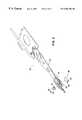
- FIG. 1is a fragmentary perspective view of a data storage system utilizing a read/write element according to the invention
- FIG. 2is a top view of a head gimbal assembly (HGA) comprised of a suspension, a slider that incorporates the read/write element and a laser assembly including a mounting block, for use in a head stack assembly (HSA);
- HGAhead gimbal assembly
- FIG. 2is a top view of a head gimbal assembly (HGA) comprised of a suspension, a slider that incorporates the read/write element and a laser assembly including a mounting block, for use in a head stack assembly (HSA);
- HGAhead gimbal assembly
- HSAhead stack assembly
- FIG. 3is an exploded perspective view of the three main components of the HGA of FIG. 2;
- FIG. 3Ais an enlarged, perspective, exploded view of the slider and the laser assembly, prior to attachment to the suspension;
- FIG. 4is a greatly enlarged, fragmentary, top view of the HGA of FIG. 2;
- FIG. 4Ais an enlarged view of part of the HGA of FIG. 4, illustrating the electrical connection to the slider pads and laser assembly;
- FIG. 4Bis a top plan view of the laser assembly of FIG. 4A showing a shorting/connecting wire cut into two segments;
- FIG. 5is an enlarged, partly cross-sectional view of the slider, illustrating a waveguide, a laser diode, the mounting block, and a suspension flexure taken along section line 5 — 5 of FIG. 4, with only selective hatching for added visual clarity;
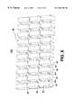
- FIG. 6is a fragmentary perspective view of an etched silicon wafer containing an array of laser mounting blocks in a “break-away” form
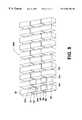
- FIG. 7is a fragmentary perspective view of the etched silicon wafer of FIG. 5 with laser diodes secured thereto;
- FIG. 8is a fragmentary perspective view of the etched silicon wafer with laser diodes of FIG. 6, illustrating the position of test probes to test the individual laser diodes;
- FIG. 9is a fragmentary perspective view of an array of several laser assemblies comprised of the etched silicon wafer and laser diodes of FIG. 7 after die bonding a shorting/connecting wire.
- FIG. 1illustrates a disk drive 10 comprised of a head stack assembly (HSA) 12 and a stack of spaced apart data storage disks or media 14 that are rotatable about a common shaft 15 .
- the head stack assembly 12is rotatable about an actuator axis 16 in the direction of the arrow C, and includes a number of actuator arms, only three of which 18 A, 18 B, 18 C are illustrated, which extend into spacings between the disks 14 .
- the head stack assembly 12further includes an E-shaped block 19 and a magnetic rotor 20 attached to the block 19 in a position diametrically opposite to the actuator arms 18 A, 18 B, 18 C.
- the rotor 20cooperates with a stator (not shown) for rotating in an arc about the actuator axis 16 .
- Energizing a coil of the rotor 20 with a direct current in one polarity or the reverse polaritycauses the head stack assembly 12 , including the actuator arms 18 A, 18 B, 18 C, to rotate about the actuator axis 16 in a direction substantially radial to the disks 14 .
- the head stack assembly 12also includes a plurality of head gimbal assemblies (HGAs) 28 that are secured to the actuator arms 18 A, 18 B, 18 C.
- HGAshead gimbal assemblies
- a HGA 28is comprised of three main components: a suspension 33 , a slider 35 and a laser assembly 22 .
- the suspension 33is formed of a load beam 36 and a flexure 40 .
- the slider 35is bonded to the flexure 40 , which, in turn, is secured to the free end of the load beam 36 .
- an exemplary embodiment of the laser assembly 22includes a laser diode 24 and a mounting block 26 .
- the laser assembly 22is secured to the flexure 40 and consequently to the free end of the load beam 36 . While the present invention will be explained in relation to a laser source, it should be understood that other light or heat sources can alternatively be used within the scope of the present invention.
- the flexure 40can be formed by means of known additive or subtractive processes, or by means of other available techniques.
- the slider 35includes a slider body 47 with a trailing edge to which a read/write element 50 is affixed.
- the slider body 47further includes an air bearing surface 48 designed to “float” the slider body 47 over the cushion of air which follows the spinning disk 14 , in order to precisely space the read/write element 50 from the magnetic medium on or within the disk 14 .
- the read/write element 50includes a plurality of pads 52 that facilitate the transfer of electrical signals to and from the read/write element 50 .
- the suspension 33includes, in addition to the load beam 36 and the flexure 40 , and a plurality of electrical traces 42 , 44 .
- the flexure 40is formed of a stainless steel frame 41 that support the slider 35 , and the traces 42 , 44 .
- the traces 42 , 44are electrically insulated from the flexure frame 41 by, for example, a plurality of polyimide pads 43 that also forms part of the of the suspension 33 .
- the flexure traces 42are connected to, and conduct electrical current to the laser diode 24 .
- the flexure traces 44are connected to the pads 52 of the read/write element 50 (FIG. 3 A), by for example ball bonding, tab bonding, wire bonding, or soldering.
- the traces 44provide signals to and from the read/write element 50 .
- the laser assembly 22includes, in addition to the laser diode 24 and the mounting block 26 , a shorting/connecting wire 57 .
- the wire 57Prior to assembling the laser assembly 22 to the suspension 33 (FIG. 3 A), the wire 57 is attached at one end to a cathode surface 63 of the laser diode 24 and at the other end to an electrical conductive surface (film or layer) 65 of the mounting block 26 .
- the conductive surface 65can be either deposited or formed on the mounting block 26 . This “shorting” connection of the wire 57 provides ESD protection to the laser diode 24 prior to the assembly of the head gimbal assembly 28 .
- the conductive surface 65 of the mounting block 26is, in turn, connected to an anode surface 69 of the laser diode 24 .
- the anode surface 69is oppositely disposed relative to the cathode surface 63 .
- the read/write element 50is deposited or formed at the trailing edged of the slider 35 , and includes for example a write element (or section) 60 and a read element (or section) 61 .
- the read element 61includes a magneto resistive (MR) read stripe 62 positioned between a first shield 80 and a second shield 85 .
- MRmagneto resistive
- the presence of a written magnetic data bit on the disk 14is sensed by the change in resistance of the read stripe 62 through two of four traces 44 of the flexure 40 .
- the traces 44are connected to the read stripe 62 through traces (not shown) on the slider 35 that are connected to the contact pads 52 of the slider 35 .
- the write element 60includes a first pole 85 which may also function as the second shield 85 of the read element 61 .
- the write element 60further includes a second pole 96 separated from the first pole 85 by the write gap 98 .
- a deposited coil 94is connected to contact pads 52 which are in turn connected to two of the four traces 44 of the slider 35 .
- When current is passed through the coil 44a magnetic field is created in the first and second poles 85 and 96 , respectively, and across the write gap 98 .
- the fringe field at the write gap 98aligns the magnetic domains in the medium of the disk 14 , as the medium passes under the write gap 98 . This forms a bit when the coercivity of the medium relative to the fringe field is sufficiently low as a result of laser heating.
- An optical waveguide 88is formed or deposited in the gap 98 between the first and second poles 85 , 96 .
- the waveguide 88has a thickness ranging between 0.1 and 1.0 microns at the laser beam exit end adjacent the air bearing surface (ABS) of the slider 35 .
- the waveguide 88tapers to a thickness ranging between 2.0 and 20.0 microns at a laser beam entry end 70 . This taper allows for the convenient alignment for coupling of the laser beam to the waveguide 88 at the entry end 70 , and for the concentration of the laser beam at the exit end.
- This concentration of the laser beamheats the medium temporarily, for sufficiently lowering its coercivity in order to enable the fringe field from the write gap 98 to orient the magnetic domains in the medium, thus creating a magnetic bit.
- the mediumreturns to a higher coercivity and is fixed at this condition making it resistant to demagnetization.
- the slider 35is bonded to the flexure 40 using for example adhesive 95 .
- one or more polyimide pads 43form an integral part of the flexure 40 adjacent the slider 35 , and the adhesive 95 is bonded to the polyimide pads 43 .
- additional electrical conductive adhesive 96is applied between the slider 35 and the flexure frame 41 in order to dissipate static electrical charge on the slider 35 .
- the polyimide pads 43are omitted and replaced by a conductive adhesive that attaches the slider 35 directly to the flexure frame 41 .
- Attachment of the laser assembly 22 to the flexure 40is performed such that a laser emitter 122 is aligned to the entry end 70 of the waveguide 88 with the proper spacing. This is done after the slider 35 is bonded to the flexure 40 .
- a preferred methodis to set a proper spacing “S” (or 74 ) between the emitter 122 of the laser diode 24 with respect to the entry end 70 of the waveguide 88 by retaining the slider 35 in a fixed position in an assembly fixture (not shown).
- the laser assembly 22is also held in the assembly fixture in a nest with an x-y-z positioning capability.
- the laser assembly 22is adjusted in the z direction until the correct spacing “S” is sensed by for example optical means.
- the spacing “S”can range for example between 2 and 50 microns, with a preferred spacing ranging between 10 and 30 microns, depending upon the size of the emitter 122 and the laser beam dispersion angle.
- the shorting/connecting wire 57(FIGS. 3 and 3A) is cut near the center of its loop into two segments 57 A, 57 B (FIGS. 4, 4 A).
- the first wire segment 57 Ahas two terminals 137 and 138 .
- Terminal 137is connected by, for example, ultrasonic wire bonding or soldering to the conductive surface 65 of the mounting block 26 , and terminal 138 is similarly connected to an electrical trace 42 .
- the second wire segment 57 Bhas two terminals 147 , 148 .
- Terminal 147is connected to the cathode 63 of the laser diode 24
- terminal 148is connected to another electrical trace 42 .
- the laser assembly 22With the laser diode 24 activated, the laser assembly 22 is moved in x and y directions while maintaining the correct z spacing “S” until the maximum output of the laser beam is sensed at the exit end of the waveguide 88 , confirming alignment.
- Adhesive 49is then applied and cured filling the gap between the mounting block 26 and flexure frame 41 (FIG. 5 ).
- the mounting block 26 of the laser assembly 22is bonded to the flexure frame 41 , it is possible to bond the mounting block 26 to the load beam 36 by making suitable modifications to the load beam 36 and the mounting block 26 of the laser assembly 22 .
- FIGS. 6, 7 , 8 and 9illustrate a preferred method of fabricating the laser assembly 22 will be explained.
- a silicon wafer 200(FIG. 6) is deep etched to form a pattern of mounting blocks 26 .
- the mounting blocks 26are connected via a web of attachment tabs 101 .
- FIG. 7illustrates the step of mounting the laser diodes 24 on the wafer 200 . While only four laser diodes 24 are shown for illustration purpose, it should be clear that in a preferred embodiment one laser diode 24 is secured to the conductive surface 65 of each mounting block 26 by, for instance, soldering the anode surface 69 of the laser diode 24 to the conductive surface 65 . This is accomplished by depositing the electrically conductive surface 65 comprised of conductive material such as gold, silver, aluminum and/or solder on the mounting blocks 26 , and then soldering the laser diodes 24 in place on the mounting blocks 26 by means of solder 170 (FIG. 4 B). The conductive surface 65 extends beyond the contact area of the laser diode 24 , occupying for example, the entire surface of the mounting block 26 upon which the laser diode 24 is soldered.
- solder 170solder 170
- FIG. 8illustrates the step of testing the laser diodes 24 , while still in the silicon wafer ( 200 ) assembly stage.
- a test probe 203is placed in contact with the cathode surface 63 of the laser diode 24 .
- Another test probe 204completes the testing circuit by contacting the electrically conductive surface 65 of the mounting block 26 , which is soldered to the anode surface 69 of the laser diode 24 .
- Activation of the testing circuitwill confirm if the laser diode 24 is operational.
- the assemblymay optionally be “burned in” by subjecting it to a critically high temperature for a sustained period prior to test to cull out laser diodes 24 prone to early failure. While FIG. 8 shows only two test probes 203 , 204 are used as part of one testing circuit, it should be clear that additional testing circuits can be used as well.
- the shorting/connecting wire 57is attached between the cathode surface 63 of the laser diode 24 and the electrically conductive surface 65 of the mounting block 26 by, for example, die bonding or ultrasonic wire bonding. Since the electrically conductive surface 65 is soldered to the anode surface 69 of the laser diode 24 (FIG. 4 B), the laser diode 24 becomes shorted out and protected against ESD damage during subsequent handling.
Landscapes
- Engineering & Computer Science (AREA)
- Chemical & Material Sciences (AREA)
- Nanotechnology (AREA)
- Crystallography & Structural Chemistry (AREA)
- Manufacturing & Machinery (AREA)
- Physics & Mathematics (AREA)
- Mathematical Physics (AREA)
- Theoretical Computer Science (AREA)
- Adjustment Of The Magnetic Head Position Track Following On Tapes (AREA)
Abstract
Description
Claims (24)
Priority Applications (1)
| Application Number | Priority Date | Filing Date | Title |
|---|---|---|---|
| US09/429,553US6404706B1 (en) | 1999-02-12 | 1999-10-28 | Laser mounting for a thermally assisted GMR head |
Applications Claiming Priority (2)
| Application Number | Priority Date | Filing Date | Title |
|---|---|---|---|
| US09/248,766US6016290A (en) | 1999-02-12 | 1999-02-12 | Read/write head with shifted waveguide |
| US09/429,553US6404706B1 (en) | 1999-02-12 | 1999-10-28 | Laser mounting for a thermally assisted GMR head |
Related Parent Applications (1)
| Application Number | Title | Priority Date | Filing Date |
|---|---|---|---|
| US09/248,766Continuation-In-PartUS6016290A (en) | 1999-02-12 | 1999-02-12 | Read/write head with shifted waveguide |
Publications (1)
| Publication Number | Publication Date |
|---|---|
| US6404706B1true US6404706B1 (en) | 2002-06-11 |
Family
ID=46276540
Family Applications (1)
| Application Number | Title | Priority Date | Filing Date |
|---|---|---|---|
| US09/429,553Expired - LifetimeUS6404706B1 (en) | 1999-02-12 | 1999-10-28 | Laser mounting for a thermally assisted GMR head |
Country Status (1)
| Country | Link |
|---|---|
| US (1) | US6404706B1 (en) |
Cited By (185)
| Publication number | Priority date | Publication date | Assignee | Title |
|---|---|---|---|---|
| US20020030935A1 (en)* | 2000-08-09 | 2002-03-14 | Xm Wong | Bonding pad of suspension circuit |
| US20030021191A1 (en)* | 2001-07-25 | 2003-01-30 | Yimin Hsu | Magnetic recording system with single coil for thermally assisted writing |
| US20030039068A1 (en)* | 2001-08-21 | 2003-02-27 | Seagate Technology Llc | Magnetic recording head including spatially-pumped spin wave mode writer |
| US6549506B1 (en)* | 2000-07-17 | 2003-04-15 | Iomega Corporation | Photo detector mounting in a head gimbal assembly used in an optical data storage device |
| US20030128633A1 (en)* | 2002-01-08 | 2003-07-10 | Seagate Technology Llc | Heat assisted magnetic recording head with hybrid write pole |
| US20030235121A1 (en)* | 2002-06-20 | 2003-12-25 | Seagate Technology Llc | Recording pole for heat assisted magnetic recording |
| WO2004001724A1 (en)* | 2002-06-19 | 2003-12-31 | Advanced Research Corporation | Optical waveguide path for a thermal-assisted magnetic recording head |
| US20040001420A1 (en)* | 2002-06-28 | 2004-01-01 | Seagate Technology Llc | Heat assisted magnetic recording head with a planar waveguide |
| US20040008591A1 (en)* | 2002-06-24 | 2004-01-15 | Seagate Technology Llc | Recording pole for delivering coincident heat and magnetic field |
| US6687195B2 (en)* | 2000-12-19 | 2004-02-03 | Sharp Kabushiki Kaisha | Magnetic recording head and magnetic recording device |
| US20040062503A1 (en)* | 2002-09-30 | 2004-04-01 | Seagate Technology Llc | Planar waveguide for heat assisted magnetic recording |
| US6731587B1 (en)* | 1999-05-19 | 2004-05-04 | Matsushita Electric Industrial Co., Ltd. | Transducer-supporting structure |
| US6741524B2 (en)* | 1999-12-28 | 2004-05-25 | Kabushiki Kaisha Toshiba | Thermally-assisted magnetic recording and reproducing device having an electron beam thermal source |
| US20040170096A1 (en)* | 2000-06-06 | 2004-09-02 | Pope Ijtsma | Method of immediate writing or reading files on a disc like recording medium |
| US20050052771A1 (en)* | 2003-09-05 | 2005-03-10 | Seagate Technology Llc | Heat assisted magnetic recording head and method |
| US20050071859A1 (en)* | 2000-06-16 | 2005-03-31 | Reinder Coehoorn | Record head for thermally assisted magnetic recording |
| US20050265139A1 (en)* | 2004-05-26 | 2005-12-01 | Seagate Technology Llc | Light delivery technique for heat assisted magnetic recording head |
| US7042810B2 (en)* | 2000-01-31 | 2006-05-09 | Kabushiki Kaisha Toshiba | Thermally-assisted magnetic recording head, method of manufacturing the same, and thermally-assisted magnetic recording apparatus |
| US20060233061A1 (en)* | 2005-04-13 | 2006-10-19 | Seagate Technology Llc | Alignment features for heat assisted magnetic recording transducers |
| US20070036040A1 (en)* | 2005-08-11 | 2007-02-15 | Seagate Technology Llc | Dual wire integrated WAMR/HAMR writing head |
| WO2007145415A1 (en)* | 2006-06-14 | 2007-12-21 | Samsung Electronics Co., Ltd. | Head gimbals assembly of hard disk and method of assembling thereof |
| US20080043360A1 (en)* | 2006-08-21 | 2008-02-21 | Tdk Corporation | Thermally assisted magnetic head |
| US20080151431A1 (en)* | 2006-12-22 | 2008-06-26 | Tdk Corporation | Thermally assisted magnetic head |
| US20080239541A1 (en)* | 2007-03-27 | 2008-10-02 | Tdk Corporation | Thermally assisted magnetic head, head gimbal assembly, and hard disk drive |
| US7532434B1 (en)* | 2001-09-06 | 2009-05-12 | Schreck Erhard T | Recessed write pole for perpendicular recording |
| US20090195930A1 (en)* | 2008-01-31 | 2009-08-06 | Lille Jeffrey S | Magnetic recording slider with flex side pads |
| US20100007980A1 (en)* | 2006-05-17 | 2010-01-14 | Samsung Electronics Co., Ltd. | Heat-assisted magnetic recording head gimbal assembly |
| US20100110590A1 (en)* | 2008-10-31 | 2010-05-06 | Nitto Denko Corporation | Suspension board with circuit |
| US20100128576A1 (en)* | 2008-11-21 | 2010-05-27 | Fang Alexander W | Integrated magnetic recording head and near field laser |
| US20100195239A1 (en)* | 2009-02-03 | 2010-08-05 | Tdk Corporation | Thermally assisted magnetic head comprising surface-emitting semiconductor laser |
| US20100195450A1 (en)* | 2009-01-30 | 2010-08-05 | Shigeyuki Sasaki | Magnetic disk drive |
| US20100195238A1 (en)* | 2009-01-30 | 2010-08-05 | Tdk Corporation | Thermally assisted magnetic head having a semiconductor surface-emitting laser |
| US20100202081A1 (en)* | 2009-02-12 | 2010-08-12 | Tdk Corporation | Thermally assisted magnetic head having a semiconductor surface-emitting laser |
| US20110026156A1 (en)* | 2009-08-03 | 2011-02-03 | Tdk Corporation | Heat-assisted magnetic recording head with laser diode |
| JP2011028828A (en)* | 2009-07-03 | 2011-02-10 | Seiko Instruments Inc | Head gimbal assembly and information recording and reproducing apparatus |
| US20110141862A1 (en)* | 2008-06-10 | 2011-06-16 | Hitachi, Ltd. | Thermally-Assisted Magnetic Recording Head |
| US8107326B1 (en) | 2010-11-15 | 2012-01-31 | Hitachi Global Storage Technologies Netherlands B.V. | Slider with integrated thermally-assisted recording (TAR) head and integrated long laser diode |
| US8134794B1 (en)* | 2009-12-23 | 2012-03-13 | Western Digital (Fremont), Llc | Method and system for providing an energy assisted magnetic recording head in a wafer packaging configuration |
| JP2012053952A (en)* | 2010-09-01 | 2012-03-15 | Dainippon Printing Co Ltd | Substrate for suspension, suspension and manufacturing method for substrate for suspension |
| US8139448B1 (en) | 2010-12-15 | 2012-03-20 | Hitachi Global Storage Technologies Netherlands B.V. | Slider with integrated thermally-assisted recording (TAR) head and vertical-cavity surface-emitting laser (VCSEL) with angled external cavity |
| US8184507B1 (en) | 2010-12-15 | 2012-05-22 | Hitachi Global Storage Technologies Netherlands B.V. | Slider with integrated thermally-assisted recording (TAR) head and long laser diode with optical body for directing laser radiation |
| US8259539B1 (en) | 2008-12-17 | 2012-09-04 | Western Digital (Fremont), Llc | Integration of a vertical cavity surface emitting laser (VCSEL) on an energy-assisted magnetic recording (EAMR) head |
| US8279719B1 (en) | 2009-10-01 | 2012-10-02 | Western Digital (Fremont), Llc | Method and system for coupling a laser with a slider in an energy assisted magnetic recording disk drive |
| CN102831903A (en)* | 2011-06-13 | 2012-12-19 | 希捷科技有限公司 | Head gimbal assembly with heat assist laser |
| US8345519B1 (en) | 2010-12-22 | 2013-01-01 | Western Digital (Fremont), Llc | Method and system for providing a suspension head bond pad design |
| US8411535B1 (en) | 2011-11-30 | 2013-04-02 | HGST Netherlands B.V. | Electrical connection for a laser diode in a tar head |
| US8456776B1 (en) | 2010-09-22 | 2013-06-04 | Western Digital Technologies, Inc. | Disk drive head gimbal assembly having a flexure bond pad shelf offset from a tongue |
| US8456963B1 (en) | 2010-04-12 | 2013-06-04 | Western Digital (Fremont), Llc | Method and system for an energy assisted magnetic recording head having a suspension-mounted laser |
| US8631561B2 (en) | 2011-11-30 | 2014-01-21 | HGST Netherlands B.V. | Method for electrically connecting an energy source to a head of a disk drive |
| US8830628B1 (en) | 2009-02-23 | 2014-09-09 | Western Digital (Fremont), Llc | Method and system for providing a perpendicular magnetic recording head |
| US8837261B1 (en) | 2013-08-27 | 2014-09-16 | HGST Netherlands B.V. | Electrical contact for an energy-assisted magnetic recording laser sub-mount |
| US8879207B1 (en) | 2011-12-20 | 2014-11-04 | Western Digital (Fremont), Llc | Method for providing a side shield for a magnetic recording transducer using an air bridge |
| US8883017B1 (en) | 2013-03-12 | 2014-11-11 | Western Digital (Fremont), Llc | Method and system for providing a read transducer having seamless interfaces |
| US8917581B1 (en) | 2013-12-18 | 2014-12-23 | Western Digital Technologies, Inc. | Self-anneal process for a near field transducer and chimney in a hard disk drive assembly |
| US8923102B1 (en) | 2013-07-16 | 2014-12-30 | Western Digital (Fremont), Llc | Optical grating coupling for interferometric waveguides in heat assisted magnetic recording heads |
| US8947985B1 (en) | 2013-07-16 | 2015-02-03 | Western Digital (Fremont), Llc | Heat assisted magnetic recording transducers having a recessed pole |
| US8953422B1 (en) | 2014-06-10 | 2015-02-10 | Western Digital (Fremont), Llc | Near field transducer using dielectric waveguide core with fine ridge feature |
| US8958272B1 (en) | 2014-06-10 | 2015-02-17 | Western Digital (Fremont), Llc | Interfering near field transducer for energy assisted magnetic recording |
| US8971160B1 (en) | 2013-12-19 | 2015-03-03 | Western Digital (Fremont), Llc | Near field transducer with high refractive index pin for heat assisted magnetic recording |
| US8970988B1 (en) | 2013-12-31 | 2015-03-03 | Western Digital (Fremont), Llc | Electric gaps and method for making electric gaps for multiple sensor arrays |
| US8976635B1 (en) | 2014-06-10 | 2015-03-10 | Western Digital (Fremont), Llc | Near field transducer driven by a transverse electric waveguide for energy assisted magnetic recording |
| US8982508B1 (en) | 2011-10-31 | 2015-03-17 | Western Digital (Fremont), Llc | Method for providing a side shield for a magnetic recording transducer |
| US8980109B1 (en) | 2012-12-11 | 2015-03-17 | Western Digital (Fremont), Llc | Method for providing a magnetic recording transducer using a combined main pole and side shield CMP for a wraparound shield scheme |
| US8988812B1 (en) | 2013-11-27 | 2015-03-24 | Western Digital (Fremont), Llc | Multi-sensor array configuration for a two-dimensional magnetic recording (TDMR) operation |
| US8984740B1 (en) | 2012-11-30 | 2015-03-24 | Western Digital (Fremont), Llc | Process for providing a magnetic recording transducer having a smooth magnetic seed layer |
| US8988825B1 (en) | 2014-02-28 | 2015-03-24 | Western Digital (Fremont, LLC | Method for fabricating a magnetic writer having half-side shields |
| US8995087B1 (en) | 2006-11-29 | 2015-03-31 | Western Digital (Fremont), Llc | Perpendicular magnetic recording write head having a wrap around shield |
| US8993217B1 (en) | 2013-04-04 | 2015-03-31 | Western Digital (Fremont), Llc | Double exposure technique for high resolution disk imaging |
| US9001628B1 (en) | 2013-12-16 | 2015-04-07 | Western Digital (Fremont), Llc | Assistant waveguides for evaluating main waveguide coupling efficiency and diode laser alignment tolerances for hard disk |
| US9001467B1 (en) | 2014-03-05 | 2015-04-07 | Western Digital (Fremont), Llc | Method for fabricating side shields in a magnetic writer |
| US8997832B1 (en) | 2010-11-23 | 2015-04-07 | Western Digital (Fremont), Llc | Method of fabricating micrometer scale components |
| US9007719B1 (en) | 2013-10-23 | 2015-04-14 | Western Digital (Fremont), Llc | Systems and methods for using double mask techniques to achieve very small features |
| US9007725B1 (en) | 2014-10-07 | 2015-04-14 | Western Digital (Fremont), Llc | Sensor with positive coupling between dual ferromagnetic free layer laminates |
| US9007879B1 (en) | 2014-06-10 | 2015-04-14 | Western Digital (Fremont), Llc | Interfering near field transducer having a wide metal bar feature for energy assisted magnetic recording |
| US9013836B1 (en) | 2013-04-02 | 2015-04-21 | Western Digital (Fremont), Llc | Method and system for providing an antiferromagnetically coupled return pole |
| US9042057B1 (en) | 2013-01-09 | 2015-05-26 | Western Digital (Fremont), Llc | Methods for providing magnetic storage elements with high magneto-resistance using Heusler alloys |
| US9042208B1 (en) | 2013-03-11 | 2015-05-26 | Western Digital Technologies, Inc. | Disk drive measuring fly height by applying a bias voltage to an electrically insulated write component of a head |
| US9042052B1 (en) | 2014-06-23 | 2015-05-26 | Western Digital (Fremont), Llc | Magnetic writer having a partially shunted coil |
| US9042051B2 (en) | 2013-08-15 | 2015-05-26 | Western Digital (Fremont), Llc | Gradient write gap for perpendicular magnetic recording writer |
| US9042058B1 (en) | 2013-10-17 | 2015-05-26 | Western Digital Technologies, Inc. | Shield designed for middle shields in a multiple sensor array |
| US9053735B1 (en) | 2014-06-20 | 2015-06-09 | Western Digital (Fremont), Llc | Method for fabricating a magnetic writer using a full-film metal planarization |
| US9064507B1 (en) | 2009-07-31 | 2015-06-23 | Western Digital (Fremont), Llc | Magnetic etch-stop layer for magnetoresistive read heads |
| US9064527B1 (en) | 2013-04-12 | 2015-06-23 | Western Digital (Fremont), Llc | High order tapered waveguide for use in a heat assisted magnetic recording head |
| US9065043B1 (en) | 2012-06-29 | 2015-06-23 | Western Digital (Fremont), Llc | Tunnel magnetoresistance read head with narrow shield-to-shield spacing |
| US9064528B1 (en) | 2013-05-17 | 2015-06-23 | Western Digital Technologies, Inc. | Interferometric waveguide usable in shingled heat assisted magnetic recording in the absence of a near-field transducer |
| US9070381B1 (en) | 2013-04-12 | 2015-06-30 | Western Digital (Fremont), Llc | Magnetic recording read transducer having a laminated free layer |
| US9082423B1 (en) | 2013-12-18 | 2015-07-14 | Western Digital (Fremont), Llc | Magnetic recording write transducer having an improved trailing surface profile |
| US9087534B1 (en) | 2011-12-20 | 2015-07-21 | Western Digital (Fremont), Llc | Method and system for providing a read transducer having soft and hard magnetic bias structures |
| US9087527B1 (en) | 2014-10-28 | 2015-07-21 | Western Digital (Fremont), Llc | Apparatus and method for middle shield connection in magnetic recording transducers |
| US9093639B2 (en) | 2012-02-21 | 2015-07-28 | Western Digital (Fremont), Llc | Methods for manufacturing a magnetoresistive structure utilizing heating and cooling |
| US9104107B1 (en) | 2013-04-03 | 2015-08-11 | Western Digital (Fremont), Llc | DUV photoresist process |
| US9111550B1 (en) | 2014-12-04 | 2015-08-18 | Western Digital (Fremont), Llc | Write transducer having a magnetic buffer layer spaced between a side shield and a write pole by non-magnetic layers |
| US9111558B1 (en) | 2014-03-14 | 2015-08-18 | Western Digital (Fremont), Llc | System and method of diffractive focusing of light in a waveguide |
| US9111564B1 (en) | 2013-04-02 | 2015-08-18 | Western Digital (Fremont), Llc | Magnetic recording writer having a main pole with multiple flare angles |
| US9123362B1 (en) | 2011-03-22 | 2015-09-01 | Western Digital (Fremont), Llc | Methods for assembling an electrically assisted magnetic recording (EAMR) head |
| US9123359B1 (en) | 2010-12-22 | 2015-09-01 | Western Digital (Fremont), Llc | Magnetic recording transducer with sputtered antiferromagnetic coupling trilayer between plated ferromagnetic shields and method of fabrication |
| US9123358B1 (en) | 2012-06-11 | 2015-09-01 | Western Digital (Fremont), Llc | Conformal high moment side shield seed layer for perpendicular magnetic recording writer |
| US9123374B1 (en) | 2015-02-12 | 2015-09-01 | Western Digital (Fremont), Llc | Heat assisted magnetic recording writer having an integrated polarization rotation plate |
| US9135930B1 (en) | 2014-03-06 | 2015-09-15 | Western Digital (Fremont), Llc | Method for fabricating a magnetic write pole using vacuum deposition |
| US9135937B1 (en) | 2014-05-09 | 2015-09-15 | Western Digital (Fremont), Llc | Current modulation on laser diode for energy assisted magnetic recording transducer |
| US9142233B1 (en) | 2014-02-28 | 2015-09-22 | Western Digital (Fremont), Llc | Heat assisted magnetic recording writer having a recessed pole |
| US9147404B1 (en) | 2015-03-31 | 2015-09-29 | Western Digital (Fremont), Llc | Method and system for providing a read transducer having a dual free layer |
| US9147408B1 (en) | 2013-12-19 | 2015-09-29 | Western Digital (Fremont), Llc | Heated AFM layer deposition and cooling process for TMR magnetic recording sensor with high pinning field |
| US9153255B1 (en) | 2014-03-05 | 2015-10-06 | Western Digital (Fremont), Llc | Method for fabricating a magnetic writer having an asymmetric gap and shields |
| US9183854B2 (en) | 2014-02-24 | 2015-11-10 | Western Digital (Fremont), Llc | Method to make interferometric taper waveguide for HAMR light delivery |
| US9190079B1 (en) | 2014-09-22 | 2015-11-17 | Western Digital (Fremont), Llc | Magnetic write pole having engineered radius of curvature and chisel angle profiles |
| US9190085B1 (en) | 2014-03-12 | 2015-11-17 | Western Digital (Fremont), Llc | Waveguide with reflective grating for localized energy intensity |
| US9194692B1 (en) | 2013-12-06 | 2015-11-24 | Western Digital (Fremont), Llc | Systems and methods for using white light interferometry to measure undercut of a bi-layer structure |
| US9202501B2 (en) | 2013-08-15 | 2015-12-01 | Seagate Technology Llc | Slider for magnetic recording apparatus with projection comprising optical turning element and methods of fabrication thereof |
| US9202493B1 (en) | 2014-02-28 | 2015-12-01 | Western Digital (Fremont), Llc | Method of making an ultra-sharp tip mode converter for a HAMR head |
| US9202480B2 (en) | 2009-10-14 | 2015-12-01 | Western Digital (Fremont), LLC. | Double patterning hard mask for damascene perpendicular magnetic recording (PMR) writer |
| US9202489B2 (en) | 2014-01-24 | 2015-12-01 | Seagate Technology Llc | Laser mounted on edge of a slider |
| US9214172B2 (en) | 2013-10-23 | 2015-12-15 | Western Digital (Fremont), Llc | Method of manufacturing a magnetic read head |
| US9214169B1 (en) | 2014-06-20 | 2015-12-15 | Western Digital (Fremont), Llc | Magnetic recording read transducer having a laminated free layer |
| US9214165B1 (en) | 2014-12-18 | 2015-12-15 | Western Digital (Fremont), Llc | Magnetic writer having a gradient in saturation magnetization of the shields |
| US9213322B1 (en) | 2012-08-16 | 2015-12-15 | Western Digital (Fremont), Llc | Methods for providing run to run process control using a dynamic tuner |
| US9230565B1 (en) | 2014-06-24 | 2016-01-05 | Western Digital (Fremont), Llc | Magnetic shield for magnetic recording head |
| US9236560B1 (en) | 2014-12-08 | 2016-01-12 | Western Digital (Fremont), Llc | Spin transfer torque tunneling magnetoresistive device having a laminated free layer with perpendicular magnetic anisotropy |
| US9245543B1 (en) | 2010-06-25 | 2016-01-26 | Western Digital (Fremont), Llc | Method for providing an energy assisted magnetic recording head having a laser integrally mounted to the slider |
| US9245562B1 (en) | 2015-03-30 | 2016-01-26 | Western Digital (Fremont), Llc | Magnetic recording writer with a composite main pole |
| US9245545B1 (en) | 2013-04-12 | 2016-01-26 | Wester Digital (Fremont), Llc | Short yoke length coils for magnetic heads in disk drives |
| JP2016015194A (en)* | 2015-09-15 | 2016-01-28 | 大日本印刷株式会社 | Substrate for suspension, suspension, and method for manufacturing substrate for suspension |
| US9251813B1 (en) | 2009-04-19 | 2016-02-02 | Western Digital (Fremont), Llc | Method of making a magnetic recording head |
| US9263067B1 (en) | 2013-05-29 | 2016-02-16 | Western Digital (Fremont), Llc | Process for making PMR writer with constant side wall angle |
| US9263071B1 (en) | 2015-03-31 | 2016-02-16 | Western Digital (Fremont), Llc | Flat NFT for heat assisted magnetic recording |
| US9269382B1 (en) | 2012-06-29 | 2016-02-23 | Western Digital (Fremont), Llc | Method and system for providing a read transducer having improved pinning of the pinned layer at higher recording densities |
| US9275657B1 (en) | 2013-08-14 | 2016-03-01 | Western Digital (Fremont), Llc | Process for making PMR writer with non-conformal side gaps |
| US9280990B1 (en) | 2013-12-11 | 2016-03-08 | Western Digital (Fremont), Llc | Method for fabricating a magnetic writer using multiple etches |
| US9286919B1 (en) | 2014-12-17 | 2016-03-15 | Western Digital (Fremont), Llc | Magnetic writer having a dual side gap |
| US9287494B1 (en) | 2013-06-28 | 2016-03-15 | Western Digital (Fremont), Llc | Magnetic tunnel junction (MTJ) with a magnesium oxide tunnel barrier |
| US9305583B1 (en) | 2014-02-18 | 2016-04-05 | Western Digital (Fremont), Llc | Method for fabricating a magnetic writer using multiple etches of damascene materials |
| US9312064B1 (en) | 2015-03-02 | 2016-04-12 | Western Digital (Fremont), Llc | Method to fabricate a magnetic head including ion milling of read gap using dual layer hard mask |
| US9318130B1 (en) | 2013-07-02 | 2016-04-19 | Western Digital (Fremont), Llc | Method to fabricate tunneling magnetic recording heads with extended pinned layer |
| US9336814B1 (en) | 2013-03-12 | 2016-05-10 | Western Digital (Fremont), Llc | Inverse tapered waveguide for use in a heat assisted magnetic recording head |
| US9343098B1 (en) | 2013-08-23 | 2016-05-17 | Western Digital (Fremont), Llc | Method for providing a heat assisted magnetic recording transducer having protective pads |
| US9343087B1 (en) | 2014-12-21 | 2016-05-17 | Western Digital (Fremont), Llc | Method for fabricating a magnetic writer having half shields |
| US9343086B1 (en) | 2013-09-11 | 2016-05-17 | Western Digital (Fremont), Llc | Magnetic recording write transducer having an improved sidewall angle profile |
| US9349392B1 (en) | 2012-05-24 | 2016-05-24 | Western Digital (Fremont), Llc | Methods for improving adhesion on dielectric substrates |
| US9349394B1 (en) | 2013-10-18 | 2016-05-24 | Western Digital (Fremont), Llc | Method for fabricating a magnetic writer having a gradient side gap |
| US9361913B1 (en) | 2013-06-03 | 2016-06-07 | Western Digital (Fremont), Llc | Recording read heads with a multi-layer AFM layer methods and apparatuses |
| US9361914B1 (en) | 2014-06-18 | 2016-06-07 | Western Digital (Fremont), Llc | Magnetic sensor with thin capping layer |
| US9368134B1 (en) | 2010-12-16 | 2016-06-14 | Western Digital (Fremont), Llc | Method and system for providing an antiferromagnetically coupled writer |
| US9384763B1 (en) | 2015-03-26 | 2016-07-05 | Western Digital (Fremont), Llc | Dual free layer magnetic reader having a rear bias structure including a soft bias layer |
| US9384765B1 (en) | 2015-09-24 | 2016-07-05 | Western Digital (Fremont), Llc | Method and system for providing a HAMR writer having improved optical efficiency |
| US9396742B1 (en) | 2012-11-30 | 2016-07-19 | Western Digital (Fremont), Llc | Magnetoresistive sensor for a magnetic storage system read head, and fabrication method thereof |
| US9396743B1 (en) | 2014-02-28 | 2016-07-19 | Western Digital (Fremont), Llc | Systems and methods for controlling soft bias thickness for tunnel magnetoresistance readers |
| US9406331B1 (en) | 2013-06-17 | 2016-08-02 | Western Digital (Fremont), Llc | Method for making ultra-narrow read sensor and read transducer device resulting therefrom |
| US9424866B1 (en) | 2015-09-24 | 2016-08-23 | Western Digital (Fremont), Llc | Heat assisted magnetic recording write apparatus having a dielectric gap |
| US9431047B1 (en) | 2013-05-01 | 2016-08-30 | Western Digital (Fremont), Llc | Method for providing an improved AFM reader shield |
| US9431039B1 (en) | 2013-05-21 | 2016-08-30 | Western Digital (Fremont), Llc | Multiple sensor array usable in two-dimensional magnetic recording |
| US9431031B1 (en) | 2015-03-24 | 2016-08-30 | Western Digital (Fremont), Llc | System and method for magnetic transducers having multiple sensors and AFC shields |
| US9431038B1 (en) | 2015-06-29 | 2016-08-30 | Western Digital (Fremont), Llc | Method for fabricating a magnetic write pole having an improved sidewall angle profile |
| US9431032B1 (en) | 2013-08-14 | 2016-08-30 | Western Digital (Fremont), Llc | Electrical connection arrangement for a multiple sensor array usable in two-dimensional magnetic recording |
| US9437251B1 (en) | 2014-12-22 | 2016-09-06 | Western Digital (Fremont), Llc | Apparatus and method having TDMR reader to reader shunts |
| US9443541B1 (en) | 2015-03-24 | 2016-09-13 | Western Digital (Fremont), Llc | Magnetic writer having a gradient in saturation magnetization of the shields and return pole |
| US9441938B1 (en) | 2013-10-08 | 2016-09-13 | Western Digital (Fremont), Llc | Test structures for measuring near field transducer disc length |
| US9449621B1 (en) | 2015-03-26 | 2016-09-20 | Western Digital (Fremont), Llc | Dual free layer magnetic reader having a rear bias structure having a high aspect ratio |
| US9449625B1 (en) | 2014-12-24 | 2016-09-20 | Western Digital (Fremont), Llc | Heat assisted magnetic recording head having a plurality of diffusion barrier layers |
| US9472216B1 (en) | 2015-09-23 | 2016-10-18 | Western Digital (Fremont), Llc | Differential dual free layer magnetic reader |
| US9484051B1 (en) | 2015-11-09 | 2016-11-01 | The Provost, Fellows, Foundation Scholars and the other members of Board, of the College of the Holy and Undivided Trinity of Queen Elizabeth near Dublin | Method and system for reducing undesirable reflections in a HAMR write apparatus |
| US9508372B1 (en) | 2015-06-03 | 2016-11-29 | Western Digital (Fremont), Llc | Shingle magnetic writer having a low sidewall angle pole |
| US9508363B1 (en) | 2014-06-17 | 2016-11-29 | Western Digital (Fremont), Llc | Method for fabricating a magnetic write pole having a leading edge bevel |
| US9508365B1 (en) | 2015-06-24 | 2016-11-29 | Western Digital (Fremont), LLC. | Magnetic reader having a crystal decoupling structure |
| US9530443B1 (en) | 2015-06-25 | 2016-12-27 | Western Digital (Fremont), Llc | Method for fabricating a magnetic recording device having a high aspect ratio structure |
| US9564150B1 (en) | 2015-11-24 | 2017-02-07 | Western Digital (Fremont), Llc | Magnetic read apparatus having an improved read sensor isolation circuit |
| US9595273B1 (en) | 2015-09-30 | 2017-03-14 | Western Digital (Fremont), Llc | Shingle magnetic writer having nonconformal shields |
| US9646639B2 (en) | 2015-06-26 | 2017-05-09 | Western Digital (Fremont), Llc | Heat assisted magnetic recording writer having integrated polarization rotation waveguides |
| US9666214B1 (en) | 2015-09-23 | 2017-05-30 | Western Digital (Fremont), Llc | Free layer magnetic reader that may have a reduced shield-to-shield spacing |
| US9721595B1 (en) | 2014-12-04 | 2017-08-01 | Western Digital (Fremont), Llc | Method for providing a storage device |
| US9741366B1 (en) | 2014-12-18 | 2017-08-22 | Western Digital (Fremont), Llc | Method for fabricating a magnetic writer having a gradient in saturation magnetization of the shields |
| US9740805B1 (en) | 2015-12-01 | 2017-08-22 | Western Digital (Fremont), Llc | Method and system for detecting hotspots for photolithographically-defined devices |
| US9754611B1 (en) | 2015-11-30 | 2017-09-05 | Western Digital (Fremont), Llc | Magnetic recording write apparatus having a stepped conformal trailing shield |
| US9767831B1 (en) | 2015-12-01 | 2017-09-19 | Western Digital (Fremont), Llc | Magnetic writer having convex trailing surface pole and conformal write gap |
| US9786301B1 (en) | 2014-12-02 | 2017-10-10 | Western Digital (Fremont), Llc | Apparatuses and methods for providing thin shields in a multiple sensor array |
| US9799351B1 (en) | 2015-11-30 | 2017-10-24 | Western Digital (Fremont), Llc | Short yoke length writer having assist coils |
| US9812155B1 (en) | 2015-11-23 | 2017-11-07 | Western Digital (Fremont), Llc | Method and system for fabricating high junction angle read sensors |
| US9842615B1 (en) | 2015-06-26 | 2017-12-12 | Western Digital (Fremont), Llc | Magnetic reader having a nonmagnetic insertion layer for the pinning layer |
| US9858951B1 (en) | 2015-12-01 | 2018-01-02 | Western Digital (Fremont), Llc | Method for providing a multilayer AFM layer in a read sensor |
| US9881638B1 (en) | 2014-12-17 | 2018-01-30 | Western Digital (Fremont), Llc | Method for providing a near-field transducer (NFT) for a heat assisted magnetic recording (HAMR) device |
| US9934811B1 (en) | 2014-03-07 | 2018-04-03 | Western Digital (Fremont), Llc | Methods for controlling stray fields of magnetic features using magneto-elastic anisotropy |
| US9953670B1 (en) | 2015-11-10 | 2018-04-24 | Western Digital (Fremont), Llc | Method and system for providing a HAMR writer including a multi-mode interference device |
| US10037770B1 (en) | 2015-11-12 | 2018-07-31 | Western Digital (Fremont), Llc | Method for providing a magnetic recording write apparatus having a seamless pole |
| US10074387B1 (en) | 2014-12-21 | 2018-09-11 | Western Digital (Fremont), Llc | Method and system for providing a read transducer having symmetric antiferromagnetically coupled shields |
| US11226457B2 (en)* | 2020-05-28 | 2022-01-18 | Cisco Technology, Inc. | Laser and photonic chip integration |
| US12400679B1 (en)* | 2024-02-27 | 2025-08-26 | Sae Magnetics (H.K.) Ltd. | Thermally assisted magnetic head, head gimbal assembly, and hard disk drive |
Citations (8)
| Publication number | Priority date | Publication date | Assignee | Title |
|---|---|---|---|---|
| US5199090A (en)* | 1992-03-06 | 1993-03-30 | Hewlett-Packard Company | Flying magnetooptical read/write head employing an optical integrated circuit waveguide |
| US5295122A (en)* | 1991-07-09 | 1994-03-15 | Fuji Xerox Co., Ltd. | Flying head of a magneto-optical recording apparatus |
| US5446613A (en)* | 1994-02-28 | 1995-08-29 | Read-Rite Corporation | Magnetic head assembly with MR sensor |
| US5576914A (en)* | 1994-11-14 | 1996-11-19 | Read-Rite Corporation | Compact read/write head having biased GMR element |
| US5986978A (en)* | 1998-01-12 | 1999-11-16 | Read-Rite Corporation | Read/write head and method for magnetic reading and magneto-optical writing on a data storage medium |
| US6016290A (en)* | 1999-02-12 | 2000-01-18 | Read-Rite Corporation | Read/write head with shifted waveguide |
| US6072151A (en)* | 1995-11-16 | 2000-06-06 | Hutchinson Technology Incorporated | Method for adjusting head suspension load |
| US6130863A (en)* | 1997-11-06 | 2000-10-10 | Read-Rite Corporation | Slider and electro-magnetic coil assembly |
- 1999
- 1999-10-28USUS09/429,553patent/US6404706B1/ennot_activeExpired - Lifetime
Patent Citations (8)
| Publication number | Priority date | Publication date | Assignee | Title |
|---|---|---|---|---|
| US5295122A (en)* | 1991-07-09 | 1994-03-15 | Fuji Xerox Co., Ltd. | Flying head of a magneto-optical recording apparatus |
| US5199090A (en)* | 1992-03-06 | 1993-03-30 | Hewlett-Packard Company | Flying magnetooptical read/write head employing an optical integrated circuit waveguide |
| US5446613A (en)* | 1994-02-28 | 1995-08-29 | Read-Rite Corporation | Magnetic head assembly with MR sensor |
| US5576914A (en)* | 1994-11-14 | 1996-11-19 | Read-Rite Corporation | Compact read/write head having biased GMR element |
| US6072151A (en)* | 1995-11-16 | 2000-06-06 | Hutchinson Technology Incorporated | Method for adjusting head suspension load |
| US6130863A (en)* | 1997-11-06 | 2000-10-10 | Read-Rite Corporation | Slider and electro-magnetic coil assembly |
| US5986978A (en)* | 1998-01-12 | 1999-11-16 | Read-Rite Corporation | Read/write head and method for magnetic reading and magneto-optical writing on a data storage medium |
| US6016290A (en)* | 1999-02-12 | 2000-01-18 | Read-Rite Corporation | Read/write head with shifted waveguide |
Cited By (247)
| Publication number | Priority date | Publication date | Assignee | Title |
|---|---|---|---|---|
| US6731587B1 (en)* | 1999-05-19 | 2004-05-04 | Matsushita Electric Industrial Co., Ltd. | Transducer-supporting structure |
| US7013473B2 (en) | 1999-05-19 | 2006-03-14 | Matsushita Electric Industrial Co., Ltd. | Transducer-supporting structure |
| US20040158847A1 (en)* | 1999-05-19 | 2004-08-12 | Osamu Mizuno | Transducer-supporting structure |
| US6741524B2 (en)* | 1999-12-28 | 2004-05-25 | Kabushiki Kaisha Toshiba | Thermally-assisted magnetic recording and reproducing device having an electron beam thermal source |
| US7042810B2 (en)* | 2000-01-31 | 2006-05-09 | Kabushiki Kaisha Toshiba | Thermally-assisted magnetic recording head, method of manufacturing the same, and thermally-assisted magnetic recording apparatus |
| US20040170096A1 (en)* | 2000-06-06 | 2004-09-02 | Pope Ijtsma | Method of immediate writing or reading files on a disc like recording medium |
| US20050071859A1 (en)* | 2000-06-16 | 2005-03-31 | Reinder Coehoorn | Record head for thermally assisted magnetic recording |
| US7069568B2 (en)* | 2000-06-16 | 2006-06-27 | Koninklijke Philips Electronics N.V. | Record head for thermally assisted magnetic recording |
| US6549506B1 (en)* | 2000-07-17 | 2003-04-15 | Iomega Corporation | Photo detector mounting in a head gimbal assembly used in an optical data storage device |
| US20020030935A1 (en)* | 2000-08-09 | 2002-03-14 | Xm Wong | Bonding pad of suspension circuit |
| US6874677B2 (en)* | 2000-08-09 | 2005-04-05 | Sae Magnetics (H.K.) Ltd. | Bonding pad of suspension circuit |
| US20030058577A1 (en)* | 2000-08-09 | 2003-03-27 | Xm Wong | Bonding pad of suspension circuit |
| US6687195B2 (en)* | 2000-12-19 | 2004-02-03 | Sharp Kabushiki Kaisha | Magnetic recording head and magnetic recording device |
| US6671127B2 (en)* | 2001-07-25 | 2003-12-30 | International Business Machines Corporation | Magnetic recording system with single coil for thermally assisted writing |
| US20030021191A1 (en)* | 2001-07-25 | 2003-01-30 | Yimin Hsu | Magnetic recording system with single coil for thermally assisted writing |
| US20030039068A1 (en)* | 2001-08-21 | 2003-02-27 | Seagate Technology Llc | Magnetic recording head including spatially-pumped spin wave mode writer |
| US6954331B2 (en) | 2001-08-21 | 2005-10-11 | Seagate Technology Llc | Magnetic recording head including spatially-pumped spin wave mode writer |
| US7532434B1 (en)* | 2001-09-06 | 2009-05-12 | Schreck Erhard T | Recessed write pole for perpendicular recording |
| US20030128633A1 (en)* | 2002-01-08 | 2003-07-10 | Seagate Technology Llc | Heat assisted magnetic recording head with hybrid write pole |
| US6996033B2 (en) | 2002-06-19 | 2006-02-07 | Advanced Research Corporation | Optical path for a thermal-assisted magnetic recording head |
| US7532435B2 (en) | 2002-06-19 | 2009-05-12 | Advanced Research Corporation | Optical path for a thermal-assisted magnetic recording head |
| US20040120064A1 (en)* | 2002-06-19 | 2004-06-24 | Dugas Matthew P. | Optical path for a thermal-assisted magnetic recording head |
| WO2004001724A1 (en)* | 2002-06-19 | 2003-12-31 | Advanced Research Corporation | Optical waveguide path for a thermal-assisted magnetic recording head |
| US20100002332A1 (en)* | 2002-06-19 | 2010-01-07 | Dugas Matthew P | Optical Path for a Thermal-Assisted Magnetic Recording Head |
| US20070008659A1 (en)* | 2002-06-19 | 2007-01-11 | Advanced Research Corporation | Optical path for a thermal-assisted magnetic recording head |
| US7944647B2 (en) | 2002-06-19 | 2011-05-17 | Advanced Research Corporation | Optical path for a thermal-assisted magnetic recording head |
| US20030235121A1 (en)* | 2002-06-20 | 2003-12-25 | Seagate Technology Llc | Recording pole for heat assisted magnetic recording |
| US7215629B2 (en) | 2002-06-20 | 2007-05-08 | Seagate Technology Llc | Magnetic recording device for heat assisted magnetic recording |
| US20070153642A1 (en)* | 2002-06-20 | 2007-07-05 | Seagate Technology Llc | Recording pole for heat assisted magnetic recording |
| US7440384B2 (en) | 2002-06-20 | 2008-10-21 | Seagate Technology Llc | Magnetic recording device for heat assisted magnetic recording |
| US20040008591A1 (en)* | 2002-06-24 | 2004-01-15 | Seagate Technology Llc | Recording pole for delivering coincident heat and magnetic field |
| US6944101B2 (en) | 2002-06-24 | 2005-09-13 | Seagate Technology Llc | Recording pole for delivering coincident heat and magnetic field |
| WO2004003891A1 (en)* | 2002-06-28 | 2004-01-08 | Seagate Technology Llc | Heat assisted magnetic recording head with a planar waveguide |
| US20040001420A1 (en)* | 2002-06-28 | 2004-01-01 | Seagate Technology Llc | Heat assisted magnetic recording head with a planar waveguide |
| US6944112B2 (en) | 2002-06-28 | 2005-09-13 | Seagate Technology Llc | Heat assisted magnetic recording head with a planar waveguide |
| US7027700B2 (en) | 2002-09-30 | 2006-04-11 | Seagate Technology Llc | Planar waveguide for heat assisted magnetic recording |
| US20040062503A1 (en)* | 2002-09-30 | 2004-04-01 | Seagate Technology Llc | Planar waveguide for heat assisted magnetic recording |
| US7155732B2 (en) | 2003-09-05 | 2006-12-26 | Seagate Technology Llc | Heat assisted magnetic recording head and method |
| US20050052771A1 (en)* | 2003-09-05 | 2005-03-10 | Seagate Technology Llc | Heat assisted magnetic recording head and method |
| US20080123219A1 (en)* | 2004-05-26 | 2008-05-29 | Seagate Technology Llc | Light Delivery Technique For Heat Assisted Magnetic Recording Head |
| US20050265139A1 (en)* | 2004-05-26 | 2005-12-01 | Seagate Technology Llc | Light delivery technique for heat assisted magnetic recording head |
| US7345840B2 (en) | 2004-05-26 | 2008-03-18 | Seagate Technology Llc | Light delivery technique for heat assisted magnetic recording head |
| US7804656B2 (en)* | 2004-05-26 | 2010-09-28 | Seagate Technology Llc | Light delivery technique for heat assisted magnetic recording head |
| US8339905B2 (en) | 2005-04-13 | 2012-12-25 | Seagate Technology Llc | Alignment features for heat assisted magnetic recording transducers |
| US20060233061A1 (en)* | 2005-04-13 | 2006-10-19 | Seagate Technology Llc | Alignment features for heat assisted magnetic recording transducers |
| US20070036040A1 (en)* | 2005-08-11 | 2007-02-15 | Seagate Technology Llc | Dual wire integrated WAMR/HAMR writing head |
| US7869309B2 (en)* | 2005-08-11 | 2011-01-11 | Seagate Technology Llc | Dual wire integrated WAMR/HAMR writing head |
| US20100007980A1 (en)* | 2006-05-17 | 2010-01-14 | Samsung Electronics Co., Ltd. | Heat-assisted magnetic recording head gimbal assembly |
| KR100955395B1 (en)* | 2006-06-14 | 2010-04-29 | 삼성전자주식회사 | Head gimbal assembly for hard disk and assembly method thereof |
| WO2007145415A1 (en)* | 2006-06-14 | 2007-12-21 | Samsung Electronics Co., Ltd. | Head gimbals assembly of hard disk and method of assembling thereof |
| US8111486B2 (en) | 2006-06-14 | 2012-02-07 | Samsung Electronics Co., Ltd. | Head gimbals assembly of hard disk and method of assembling thereof |
| US20090323224A1 (en)* | 2006-06-14 | 2009-12-31 | Samsung Electronics Co., Ltd. | Head gimbals assembly of hard disk and method of assembling thereof |
| US20080043360A1 (en)* | 2006-08-21 | 2008-02-21 | Tdk Corporation | Thermally assisted magnetic head |
| US7804655B2 (en)* | 2006-08-21 | 2010-09-28 | Tdk Corporation | Thermally assisted magnetic head |
| US8995087B1 (en) | 2006-11-29 | 2015-03-31 | Western Digital (Fremont), Llc | Perpendicular magnetic recording write head having a wrap around shield |
| US7710677B2 (en)* | 2006-12-22 | 2010-05-04 | Tdk Corporation | Thermally assisted magnetic head |
| US20080151431A1 (en)* | 2006-12-22 | 2008-06-26 | Tdk Corporation | Thermally assisted magnetic head |
| US8295010B2 (en)* | 2007-03-27 | 2012-10-23 | Tdk Corporation | Thermally assisted magnetic head, head gimbal assembly, and hard disk drive |
| US20080239541A1 (en)* | 2007-03-27 | 2008-10-02 | Tdk Corporation | Thermally assisted magnetic head, head gimbal assembly, and hard disk drive |
| US20090195930A1 (en)* | 2008-01-31 | 2009-08-06 | Lille Jeffrey S | Magnetic recording slider with flex side pads |
| US8300503B2 (en)* | 2008-06-10 | 2012-10-30 | Hitachi, Ltd. | Thermally-assisted magnetic recording head |
| US20110141862A1 (en)* | 2008-06-10 | 2011-06-16 | Hitachi, Ltd. | Thermally-Assisted Magnetic Recording Head |
| US20100110590A1 (en)* | 2008-10-31 | 2010-05-06 | Nitto Denko Corporation | Suspension board with circuit |
| US8587904B2 (en)* | 2008-10-31 | 2013-11-19 | Nitto Denko Corporation | Suspension board with circuit having a light emitting device exposed from a surface thereof opposite to that on which a slider is mounted |
| US8767352B2 (en) | 2008-10-31 | 2014-07-01 | Nitto Denko Corporation | Suspension board with circuit having an opening extending therethrough in the thickness direction for light emitted from a light emitting device |
| US20100128576A1 (en)* | 2008-11-21 | 2010-05-27 | Fang Alexander W | Integrated magnetic recording head and near field laser |
| US8495813B1 (en) | 2008-12-17 | 2013-07-30 | Western Digital (Fremont), Llc | Method of making an energy-assisted magnetic recording apparatus |
| US8259539B1 (en) | 2008-12-17 | 2012-09-04 | Western Digital (Fremont), Llc | Integration of a vertical cavity surface emitting laser (VCSEL) on an energy-assisted magnetic recording (EAMR) head |
| US20100195450A1 (en)* | 2009-01-30 | 2010-08-05 | Shigeyuki Sasaki | Magnetic disk drive |
| US8000175B2 (en)* | 2009-01-30 | 2011-08-16 | Tdk Corporation | Thermally assisted magnetic head having a semiconductor surface-emitting laser |
| US20100195238A1 (en)* | 2009-01-30 | 2010-08-05 | Tdk Corporation | Thermally assisted magnetic head having a semiconductor surface-emitting laser |
| US8355298B2 (en)* | 2009-01-30 | 2013-01-15 | Hitachi, Ltd. | Magnetic recording head having a flexible heat-conductive member of predetermined curvature |
| US7936643B2 (en)* | 2009-02-03 | 2011-05-03 | Tdk Corporation | Thermal assisted magnetic recording head having surface-emitting semiconductor laser |
| US20100195239A1 (en)* | 2009-02-03 | 2010-08-05 | Tdk Corporation | Thermally assisted magnetic head comprising surface-emitting semiconductor laser |
| US20100202081A1 (en)* | 2009-02-12 | 2010-08-12 | Tdk Corporation | Thermally assisted magnetic head having a semiconductor surface-emitting laser |
| US7898909B2 (en)* | 2009-02-12 | 2011-03-01 | Tdk Corporation | Thermal-assisted magnetic recording head having substrate and light reflection section |
| US8830628B1 (en) | 2009-02-23 | 2014-09-09 | Western Digital (Fremont), Llc | Method and system for providing a perpendicular magnetic recording head |
| US9251813B1 (en) | 2009-04-19 | 2016-02-02 | Western Digital (Fremont), Llc | Method of making a magnetic recording head |
| JP2011028828A (en)* | 2009-07-03 | 2011-02-10 | Seiko Instruments Inc | Head gimbal assembly and information recording and reproducing apparatus |
| US9064507B1 (en) | 2009-07-31 | 2015-06-23 | Western Digital (Fremont), Llc | Magnetic etch-stop layer for magnetoresistive read heads |
| US20110026156A1 (en)* | 2009-08-03 | 2011-02-03 | Tdk Corporation | Heat-assisted magnetic recording head with laser diode |
| US8391106B2 (en)* | 2009-08-03 | 2013-03-05 | Tdk Corporation | Heat-assisted magnetic recording head with laser diode |
| US8279719B1 (en) | 2009-10-01 | 2012-10-02 | Western Digital (Fremont), Llc | Method and system for coupling a laser with a slider in an energy assisted magnetic recording disk drive |
| US9202480B2 (en) | 2009-10-14 | 2015-12-01 | Western Digital (Fremont), LLC. | Double patterning hard mask for damascene perpendicular magnetic recording (PMR) writer |
| US8134794B1 (en)* | 2009-12-23 | 2012-03-13 | Western Digital (Fremont), Llc | Method and system for providing an energy assisted magnetic recording head in a wafer packaging configuration |
| US8456963B1 (en) | 2010-04-12 | 2013-06-04 | Western Digital (Fremont), Llc | Method and system for an energy assisted magnetic recording head having a suspension-mounted laser |
| US9245543B1 (en) | 2010-06-25 | 2016-01-26 | Western Digital (Fremont), Llc | Method for providing an energy assisted magnetic recording head having a laser integrally mounted to the slider |
| JP2012053952A (en)* | 2010-09-01 | 2012-03-15 | Dainippon Printing Co Ltd | Substrate for suspension, suspension and manufacturing method for substrate for suspension |
| US8456776B1 (en) | 2010-09-22 | 2013-06-04 | Western Digital Technologies, Inc. | Disk drive head gimbal assembly having a flexure bond pad shelf offset from a tongue |
| US8107326B1 (en) | 2010-11-15 | 2012-01-31 | Hitachi Global Storage Technologies Netherlands B.V. | Slider with integrated thermally-assisted recording (TAR) head and integrated long laser diode |
| US9672847B2 (en) | 2010-11-23 | 2017-06-06 | Western Digital (Fremont), Llc | Micrometer scale components |
| US9159345B1 (en) | 2010-11-23 | 2015-10-13 | Western Digital (Fremont), Llc | Micrometer scale components |
| US8997832B1 (en) | 2010-11-23 | 2015-04-07 | Western Digital (Fremont), Llc | Method of fabricating micrometer scale components |
| US8139448B1 (en) | 2010-12-15 | 2012-03-20 | Hitachi Global Storage Technologies Netherlands B.V. | Slider with integrated thermally-assisted recording (TAR) head and vertical-cavity surface-emitting laser (VCSEL) with angled external cavity |
| US8184507B1 (en) | 2010-12-15 | 2012-05-22 | Hitachi Global Storage Technologies Netherlands B.V. | Slider with integrated thermally-assisted recording (TAR) head and long laser diode with optical body for directing laser radiation |
| US9368134B1 (en) | 2010-12-16 | 2016-06-14 | Western Digital (Fremont), Llc | Method and system for providing an antiferromagnetically coupled writer |
| US8345519B1 (en) | 2010-12-22 | 2013-01-01 | Western Digital (Fremont), Llc | Method and system for providing a suspension head bond pad design |
| US9123359B1 (en) | 2010-12-22 | 2015-09-01 | Western Digital (Fremont), Llc | Magnetic recording transducer with sputtered antiferromagnetic coupling trilayer between plated ferromagnetic shields and method of fabrication |
| US9123362B1 (en) | 2011-03-22 | 2015-09-01 | Western Digital (Fremont), Llc | Methods for assembling an electrically assisted magnetic recording (EAMR) head |
| CN102831903A (en)* | 2011-06-13 | 2012-12-19 | 希捷科技有限公司 | Head gimbal assembly with heat assist laser |
| CN102831903B (en)* | 2011-06-13 | 2015-09-23 | 希捷科技有限公司 | Data storage device, data storage device and forming method thereof |
| US8755254B2 (en) | 2011-06-13 | 2014-06-17 | Seagate Technology Llc | Head gimbal assembly with heat assist laser |
| US8982508B1 (en) | 2011-10-31 | 2015-03-17 | Western Digital (Fremont), Llc | Method for providing a side shield for a magnetic recording transducer |
| US8411535B1 (en) | 2011-11-30 | 2013-04-02 | HGST Netherlands B.V. | Electrical connection for a laser diode in a tar head |
| US8631561B2 (en) | 2011-11-30 | 2014-01-21 | HGST Netherlands B.V. | Method for electrically connecting an energy source to a head of a disk drive |
| US8879207B1 (en) | 2011-12-20 | 2014-11-04 | Western Digital (Fremont), Llc | Method for providing a side shield for a magnetic recording transducer using an air bridge |
| US9087534B1 (en) | 2011-12-20 | 2015-07-21 | Western Digital (Fremont), Llc | Method and system for providing a read transducer having soft and hard magnetic bias structures |
| US9093639B2 (en) | 2012-02-21 | 2015-07-28 | Western Digital (Fremont), Llc | Methods for manufacturing a magnetoresistive structure utilizing heating and cooling |
| US9940950B2 (en) | 2012-05-24 | 2018-04-10 | Western Digital (Fremont), Llc | Methods for improving adhesion on dielectric substrates |
| US9349392B1 (en) | 2012-05-24 | 2016-05-24 | Western Digital (Fremont), Llc | Methods for improving adhesion on dielectric substrates |
| US9123358B1 (en) | 2012-06-11 | 2015-09-01 | Western Digital (Fremont), Llc | Conformal high moment side shield seed layer for perpendicular magnetic recording writer |
| US9412400B2 (en) | 2012-06-29 | 2016-08-09 | Western Digital (Fremont), Llc | Tunnel magnetoresistance read head with narrow shield-to-shield spacing |
| US9065043B1 (en) | 2012-06-29 | 2015-06-23 | Western Digital (Fremont), Llc | Tunnel magnetoresistance read head with narrow shield-to-shield spacing |
| US9269382B1 (en) | 2012-06-29 | 2016-02-23 | Western Digital (Fremont), Llc | Method and system for providing a read transducer having improved pinning of the pinned layer at higher recording densities |
| US9213322B1 (en) | 2012-08-16 | 2015-12-15 | Western Digital (Fremont), Llc | Methods for providing run to run process control using a dynamic tuner |
| US9396742B1 (en) | 2012-11-30 | 2016-07-19 | Western Digital (Fremont), Llc | Magnetoresistive sensor for a magnetic storage system read head, and fabrication method thereof |
| US8984740B1 (en) | 2012-11-30 | 2015-03-24 | Western Digital (Fremont), Llc | Process for providing a magnetic recording transducer having a smooth magnetic seed layer |
| US8980109B1 (en) | 2012-12-11 | 2015-03-17 | Western Digital (Fremont), Llc | Method for providing a magnetic recording transducer using a combined main pole and side shield CMP for a wraparound shield scheme |
| US9042057B1 (en) | 2013-01-09 | 2015-05-26 | Western Digital (Fremont), Llc | Methods for providing magnetic storage elements with high magneto-resistance using Heusler alloys |
| US9042208B1 (en) | 2013-03-11 | 2015-05-26 | Western Digital Technologies, Inc. | Disk drive measuring fly height by applying a bias voltage to an electrically insulated write component of a head |
| US8883017B1 (en) | 2013-03-12 | 2014-11-11 | Western Digital (Fremont), Llc | Method and system for providing a read transducer having seamless interfaces |
| US9336814B1 (en) | 2013-03-12 | 2016-05-10 | Western Digital (Fremont), Llc | Inverse tapered waveguide for use in a heat assisted magnetic recording head |
| US9013836B1 (en) | 2013-04-02 | 2015-04-21 | Western Digital (Fremont), Llc | Method and system for providing an antiferromagnetically coupled return pole |
| US9111564B1 (en) | 2013-04-02 | 2015-08-18 | Western Digital (Fremont), Llc | Magnetic recording writer having a main pole with multiple flare angles |
| US9104107B1 (en) | 2013-04-03 | 2015-08-11 | Western Digital (Fremont), Llc | DUV photoresist process |
| US8993217B1 (en) | 2013-04-04 | 2015-03-31 | Western Digital (Fremont), Llc | Double exposure technique for high resolution disk imaging |
| US9064527B1 (en) | 2013-04-12 | 2015-06-23 | Western Digital (Fremont), Llc | High order tapered waveguide for use in a heat assisted magnetic recording head |
| US9070381B1 (en) | 2013-04-12 | 2015-06-30 | Western Digital (Fremont), Llc | Magnetic recording read transducer having a laminated free layer |
| US9245545B1 (en) | 2013-04-12 | 2016-01-26 | Wester Digital (Fremont), Llc | Short yoke length coils for magnetic heads in disk drives |
| US9431047B1 (en) | 2013-05-01 | 2016-08-30 | Western Digital (Fremont), Llc | Method for providing an improved AFM reader shield |
| US9064528B1 (en) | 2013-05-17 | 2015-06-23 | Western Digital Technologies, Inc. | Interferometric waveguide usable in shingled heat assisted magnetic recording in the absence of a near-field transducer |
| US9431039B1 (en) | 2013-05-21 | 2016-08-30 | Western Digital (Fremont), Llc | Multiple sensor array usable in two-dimensional magnetic recording |
| US9263067B1 (en) | 2013-05-29 | 2016-02-16 | Western Digital (Fremont), Llc | Process for making PMR writer with constant side wall angle |
| US9361913B1 (en) | 2013-06-03 | 2016-06-07 | Western Digital (Fremont), Llc | Recording read heads with a multi-layer AFM layer methods and apparatuses |
| US9406331B1 (en) | 2013-06-17 | 2016-08-02 | Western Digital (Fremont), Llc | Method for making ultra-narrow read sensor and read transducer device resulting therefrom |
| US9287494B1 (en) | 2013-06-28 | 2016-03-15 | Western Digital (Fremont), Llc | Magnetic tunnel junction (MTJ) with a magnesium oxide tunnel barrier |
| US9318130B1 (en) | 2013-07-02 | 2016-04-19 | Western Digital (Fremont), Llc | Method to fabricate tunneling magnetic recording heads with extended pinned layer |
| US8923102B1 (en) | 2013-07-16 | 2014-12-30 | Western Digital (Fremont), Llc | Optical grating coupling for interferometric waveguides in heat assisted magnetic recording heads |
| US8947985B1 (en) | 2013-07-16 | 2015-02-03 | Western Digital (Fremont), Llc | Heat assisted magnetic recording transducers having a recessed pole |
| US9431032B1 (en) | 2013-08-14 | 2016-08-30 | Western Digital (Fremont), Llc | Electrical connection arrangement for a multiple sensor array usable in two-dimensional magnetic recording |
| US9275657B1 (en) | 2013-08-14 | 2016-03-01 | Western Digital (Fremont), Llc | Process for making PMR writer with non-conformal side gaps |
| US9042051B2 (en) | 2013-08-15 | 2015-05-26 | Western Digital (Fremont), Llc | Gradient write gap for perpendicular magnetic recording writer |
| US9336801B2 (en) | 2013-08-15 | 2016-05-10 | Seagate Technology Llc | Slider for magnetic recording apparatus with projection comprising optical turning element and methods of fabrication thereof |
| US9202501B2 (en) | 2013-08-15 | 2015-12-01 | Seagate Technology Llc | Slider for magnetic recording apparatus with projection comprising optical turning element and methods of fabrication thereof |
| US9343098B1 (en) | 2013-08-23 | 2016-05-17 | Western Digital (Fremont), Llc | Method for providing a heat assisted magnetic recording transducer having protective pads |
| US8837261B1 (en) | 2013-08-27 | 2014-09-16 | HGST Netherlands B.V. | Electrical contact for an energy-assisted magnetic recording laser sub-mount |
| US9343086B1 (en) | 2013-09-11 | 2016-05-17 | Western Digital (Fremont), Llc | Magnetic recording write transducer having an improved sidewall angle profile |
| US9441938B1 (en) | 2013-10-08 | 2016-09-13 | Western Digital (Fremont), Llc | Test structures for measuring near field transducer disc length |
| US9042058B1 (en) | 2013-10-17 | 2015-05-26 | Western Digital Technologies, Inc. | Shield designed for middle shields in a multiple sensor array |
| US9349394B1 (en) | 2013-10-18 | 2016-05-24 | Western Digital (Fremont), Llc | Method for fabricating a magnetic writer having a gradient side gap |
| US9830936B2 (en) | 2013-10-23 | 2017-11-28 | Western Digital (Fremont), Llc | Magnetic read head with antiferromagentic layer |
| US9007719B1 (en) | 2013-10-23 | 2015-04-14 | Western Digital (Fremont), Llc | Systems and methods for using double mask techniques to achieve very small features |
| US9214172B2 (en) | 2013-10-23 | 2015-12-15 | Western Digital (Fremont), Llc | Method of manufacturing a magnetic read head |
| US8988812B1 (en) | 2013-11-27 | 2015-03-24 | Western Digital (Fremont), Llc | Multi-sensor array configuration for a two-dimensional magnetic recording (TDMR) operation |
| US9194692B1 (en) | 2013-12-06 | 2015-11-24 | Western Digital (Fremont), Llc | Systems and methods for using white light interferometry to measure undercut of a bi-layer structure |
| US9280990B1 (en) | 2013-12-11 | 2016-03-08 | Western Digital (Fremont), Llc | Method for fabricating a magnetic writer using multiple etches |
| US9001628B1 (en) | 2013-12-16 | 2015-04-07 | Western Digital (Fremont), Llc | Assistant waveguides for evaluating main waveguide coupling efficiency and diode laser alignment tolerances for hard disk |
| US9082423B1 (en) | 2013-12-18 | 2015-07-14 | Western Digital (Fremont), Llc | Magnetic recording write transducer having an improved trailing surface profile |
| US8917581B1 (en) | 2013-12-18 | 2014-12-23 | Western Digital Technologies, Inc. | Self-anneal process for a near field transducer and chimney in a hard disk drive assembly |
| US8971160B1 (en) | 2013-12-19 | 2015-03-03 | Western Digital (Fremont), Llc | Near field transducer with high refractive index pin for heat assisted magnetic recording |
| US9147408B1 (en) | 2013-12-19 | 2015-09-29 | Western Digital (Fremont), Llc | Heated AFM layer deposition and cooling process for TMR magnetic recording sensor with high pinning field |
| US8970988B1 (en) | 2013-12-31 | 2015-03-03 | Western Digital (Fremont), Llc | Electric gaps and method for making electric gaps for multiple sensor arrays |
| US9202489B2 (en) | 2014-01-24 | 2015-12-01 | Seagate Technology Llc | Laser mounted on edge of a slider |
| US9305583B1 (en) | 2014-02-18 | 2016-04-05 | Western Digital (Fremont), Llc | Method for fabricating a magnetic writer using multiple etches of damascene materials |
| US9183854B2 (en) | 2014-02-24 | 2015-11-10 | Western Digital (Fremont), Llc | Method to make interferometric taper waveguide for HAMR light delivery |
| US9396743B1 (en) | 2014-02-28 | 2016-07-19 | Western Digital (Fremont), Llc | Systems and methods for controlling soft bias thickness for tunnel magnetoresistance readers |
| US9142233B1 (en) | 2014-02-28 | 2015-09-22 | Western Digital (Fremont), Llc | Heat assisted magnetic recording writer having a recessed pole |
| US9202493B1 (en) | 2014-02-28 | 2015-12-01 | Western Digital (Fremont), Llc | Method of making an ultra-sharp tip mode converter for a HAMR head |
| US8988825B1 (en) | 2014-02-28 | 2015-03-24 | Western Digital (Fremont, LLC | Method for fabricating a magnetic writer having half-side shields |
| US9001467B1 (en) | 2014-03-05 | 2015-04-07 | Western Digital (Fremont), Llc | Method for fabricating side shields in a magnetic writer |
| US9349393B2 (en) | 2014-03-05 | 2016-05-24 | Western Digital (Fremont), Llc | Magnetic writer having an asymmetric gap and shields |
| US9153255B1 (en) | 2014-03-05 | 2015-10-06 | Western Digital (Fremont), Llc | Method for fabricating a magnetic writer having an asymmetric gap and shields |
| US9135930B1 (en) | 2014-03-06 | 2015-09-15 | Western Digital (Fremont), Llc | Method for fabricating a magnetic write pole using vacuum deposition |
| US9934811B1 (en) | 2014-03-07 | 2018-04-03 | Western Digital (Fremont), Llc | Methods for controlling stray fields of magnetic features using magneto-elastic anisotropy |
| US9495984B2 (en) | 2014-03-12 | 2016-11-15 | Western Digital (Fremont), Llc | Waveguide with reflective grating for localized energy intensity |
| US9190085B1 (en) | 2014-03-12 | 2015-11-17 | Western Digital (Fremont), Llc | Waveguide with reflective grating for localized energy intensity |
| US9111558B1 (en) | 2014-03-14 | 2015-08-18 | Western Digital (Fremont), Llc | System and method of diffractive focusing of light in a waveguide |
| US9135937B1 (en) | 2014-05-09 | 2015-09-15 | Western Digital (Fremont), Llc | Current modulation on laser diode for energy assisted magnetic recording transducer |
| US9007879B1 (en) | 2014-06-10 | 2015-04-14 | Western Digital (Fremont), Llc | Interfering near field transducer having a wide metal bar feature for energy assisted magnetic recording |
| US8953422B1 (en) | 2014-06-10 | 2015-02-10 | Western Digital (Fremont), Llc | Near field transducer using dielectric waveguide core with fine ridge feature |
| US9311952B2 (en) | 2014-06-10 | 2016-04-12 | Western Digital (Fremont), Llc | Interfering near field transducer for energy assisted magnetic recording |
| US8976635B1 (en) | 2014-06-10 | 2015-03-10 | Western Digital (Fremont), Llc | Near field transducer driven by a transverse electric waveguide for energy assisted magnetic recording |
| US8958272B1 (en) | 2014-06-10 | 2015-02-17 | Western Digital (Fremont), Llc | Interfering near field transducer for energy assisted magnetic recording |
| US9159346B1 (en) | 2014-06-10 | 2015-10-13 | Western Digital (Fremont), Llc | Near field transducer using dielectric waveguide core with fine ridge feature |
| US9508363B1 (en) | 2014-06-17 | 2016-11-29 | Western Digital (Fremont), Llc | Method for fabricating a magnetic write pole having a leading edge bevel |
| US9361914B1 (en) | 2014-06-18 | 2016-06-07 | Western Digital (Fremont), Llc | Magnetic sensor with thin capping layer |
| US9214169B1 (en) | 2014-06-20 | 2015-12-15 | Western Digital (Fremont), Llc | Magnetic recording read transducer having a laminated free layer |
| US9053735B1 (en) | 2014-06-20 | 2015-06-09 | Western Digital (Fremont), Llc | Method for fabricating a magnetic writer using a full-film metal planarization |
| US9042052B1 (en) | 2014-06-23 | 2015-05-26 | Western Digital (Fremont), Llc | Magnetic writer having a partially shunted coil |
| US9230565B1 (en) | 2014-06-24 | 2016-01-05 | Western Digital (Fremont), Llc | Magnetic shield for magnetic recording head |
| US9190079B1 (en) | 2014-09-22 | 2015-11-17 | Western Digital (Fremont), Llc | Magnetic write pole having engineered radius of curvature and chisel angle profiles |
| US9007725B1 (en) | 2014-10-07 | 2015-04-14 | Western Digital (Fremont), Llc | Sensor with positive coupling between dual ferromagnetic free layer laminates |
| US9087527B1 (en) | 2014-10-28 | 2015-07-21 | Western Digital (Fremont), Llc | Apparatus and method for middle shield connection in magnetic recording transducers |
| US9786301B1 (en) | 2014-12-02 | 2017-10-10 | Western Digital (Fremont), Llc | Apparatuses and methods for providing thin shields in a multiple sensor array |
| US9111550B1 (en) | 2014-12-04 | 2015-08-18 | Western Digital (Fremont), Llc | Write transducer having a magnetic buffer layer spaced between a side shield and a write pole by non-magnetic layers |
| US9721595B1 (en) | 2014-12-04 | 2017-08-01 | Western Digital (Fremont), Llc | Method for providing a storage device |
| US9236560B1 (en) | 2014-12-08 | 2016-01-12 | Western Digital (Fremont), Llc | Spin transfer torque tunneling magnetoresistive device having a laminated free layer with perpendicular magnetic anisotropy |
| US9705072B2 (en) | 2014-12-08 | 2017-07-11 | Western Digital (Fremont), Llc | Spin transfer torque tunneling magnetoresistive device having a laminated free layer with perpendicular magnetic anisotropy |
| US9286919B1 (en) | 2014-12-17 | 2016-03-15 | Western Digital (Fremont), Llc | Magnetic writer having a dual side gap |
| US10553241B2 (en) | 2014-12-17 | 2020-02-04 | Western Digital Technologies, Inc. | Near-field transducer (NFT) for a heat assisted magnetic recording (HAMR) device |
| US9881638B1 (en) | 2014-12-17 | 2018-01-30 | Western Digital (Fremont), Llc | Method for providing a near-field transducer (NFT) for a heat assisted magnetic recording (HAMR) device |
| US9214165B1 (en) | 2014-12-18 | 2015-12-15 | Western Digital (Fremont), Llc | Magnetic writer having a gradient in saturation magnetization of the shields |
| US9741366B1 (en) | 2014-12-18 | 2017-08-22 | Western Digital (Fremont), Llc | Method for fabricating a magnetic writer having a gradient in saturation magnetization of the shields |
| US9343087B1 (en) | 2014-12-21 | 2016-05-17 | Western Digital (Fremont), Llc | Method for fabricating a magnetic writer having half shields |
| US10074387B1 (en) | 2014-12-21 | 2018-09-11 | Western Digital (Fremont), Llc | Method and system for providing a read transducer having symmetric antiferromagnetically coupled shields |
| US9437251B1 (en) | 2014-12-22 | 2016-09-06 | Western Digital (Fremont), Llc | Apparatus and method having TDMR reader to reader shunts |
| US9449625B1 (en) | 2014-12-24 | 2016-09-20 | Western Digital (Fremont), Llc | Heat assisted magnetic recording head having a plurality of diffusion barrier layers |
| US9123374B1 (en) | 2015-02-12 | 2015-09-01 | Western Digital (Fremont), Llc | Heat assisted magnetic recording writer having an integrated polarization rotation plate |
| US9312064B1 (en) | 2015-03-02 | 2016-04-12 | Western Digital (Fremont), Llc | Method to fabricate a magnetic head including ion milling of read gap using dual layer hard mask |
| US9431031B1 (en) | 2015-03-24 | 2016-08-30 | Western Digital (Fremont), Llc | System and method for magnetic transducers having multiple sensors and AFC shields |
| US9443541B1 (en) | 2015-03-24 | 2016-09-13 | Western Digital (Fremont), Llc | Magnetic writer having a gradient in saturation magnetization of the shields and return pole |
| US9922672B1 (en) | 2015-03-26 | 2018-03-20 | Western Digital (Fremont), Llc | Dual free layer magnetic reader having a rear bias structure having a high aspect ratio |
| US9384763B1 (en) | 2015-03-26 | 2016-07-05 | Western Digital (Fremont), Llc | Dual free layer magnetic reader having a rear bias structure including a soft bias layer |
| US9449621B1 (en) | 2015-03-26 | 2016-09-20 | Western Digital (Fremont), Llc | Dual free layer magnetic reader having a rear bias structure having a high aspect ratio |
| US9245562B1 (en) | 2015-03-30 | 2016-01-26 | Western Digital (Fremont), Llc | Magnetic recording writer with a composite main pole |
| US9263071B1 (en) | 2015-03-31 | 2016-02-16 | Western Digital (Fremont), Llc | Flat NFT for heat assisted magnetic recording |
| US9147404B1 (en) | 2015-03-31 | 2015-09-29 | Western Digital (Fremont), Llc | Method and system for providing a read transducer having a dual free layer |
| US9508372B1 (en) | 2015-06-03 | 2016-11-29 | Western Digital (Fremont), Llc | Shingle magnetic writer having a low sidewall angle pole |
| US9508365B1 (en) | 2015-06-24 | 2016-11-29 | Western Digital (Fremont), LLC. | Magnetic reader having a crystal decoupling structure |
| US9530443B1 (en) | 2015-06-25 | 2016-12-27 | Western Digital (Fremont), Llc | Method for fabricating a magnetic recording device having a high aspect ratio structure |
| US10242700B2 (en) | 2015-06-26 | 2019-03-26 | Western Digital (Fremont), Llc | Magnetic reader having a nonmagnetic insertion layer for the pinning layer |
| US9646639B2 (en) | 2015-06-26 | 2017-05-09 | Western Digital (Fremont), Llc | Heat assisted magnetic recording writer having integrated polarization rotation waveguides |
| US10037773B2 (en) | 2015-06-26 | 2018-07-31 | Western Digital (Fremont), Llc | Heat assisted magnetic recording writer having integrated polarization rotation waveguides |
| US9842615B1 (en) | 2015-06-26 | 2017-12-12 | Western Digital (Fremont), Llc | Magnetic reader having a nonmagnetic insertion layer for the pinning layer |
| US9431038B1 (en) | 2015-06-29 | 2016-08-30 | Western Digital (Fremont), Llc | Method for fabricating a magnetic write pole having an improved sidewall angle profile |
| JP2016015194A (en)* | 2015-09-15 | 2016-01-28 | 大日本印刷株式会社 | Substrate for suspension, suspension, and method for manufacturing substrate for suspension |
| US9666214B1 (en) | 2015-09-23 | 2017-05-30 | Western Digital (Fremont), Llc | Free layer magnetic reader that may have a reduced shield-to-shield spacing |
| US9472216B1 (en) | 2015-09-23 | 2016-10-18 | Western Digital (Fremont), Llc | Differential dual free layer magnetic reader |
| US9384765B1 (en) | 2015-09-24 | 2016-07-05 | Western Digital (Fremont), Llc | Method and system for providing a HAMR writer having improved optical efficiency |
| US9424866B1 (en) | 2015-09-24 | 2016-08-23 | Western Digital (Fremont), Llc | Heat assisted magnetic recording write apparatus having a dielectric gap |
| US9595273B1 (en) | 2015-09-30 | 2017-03-14 | Western Digital (Fremont), Llc | Shingle magnetic writer having nonconformal shields |
| US9484051B1 (en) | 2015-11-09 | 2016-11-01 | The Provost, Fellows, Foundation Scholars and the other members of Board, of the College of the Holy and Undivided Trinity of Queen Elizabeth near Dublin | Method and system for reducing undesirable reflections in a HAMR write apparatus |
| US9953670B1 (en) | 2015-11-10 | 2018-04-24 | Western Digital (Fremont), Llc | Method and system for providing a HAMR writer including a multi-mode interference device |
| US10381029B2 (en) | 2015-11-10 | 2019-08-13 | Western Digital (Fremont), Llc | Method and system for providing a HAMR writer including a multi-mode interference device |
| US10037770B1 (en) | 2015-11-12 | 2018-07-31 | Western Digital (Fremont), Llc | Method for providing a magnetic recording write apparatus having a seamless pole |
| US9812155B1 (en) | 2015-11-23 | 2017-11-07 | Western Digital (Fremont), Llc | Method and system for fabricating high junction angle read sensors |
| US9564150B1 (en) | 2015-11-24 | 2017-02-07 | Western Digital (Fremont), Llc | Magnetic read apparatus having an improved read sensor isolation circuit |
| US9754611B1 (en) | 2015-11-30 | 2017-09-05 | Western Digital (Fremont), Llc | Magnetic recording write apparatus having a stepped conformal trailing shield |
| US10121495B2 (en) | 2015-11-30 | 2018-11-06 | Western Digital (Fremont), Llc | Magnetic recording write apparatus having a stepped conformal trailing shield |
| US9799351B1 (en) | 2015-11-30 | 2017-10-24 | Western Digital (Fremont), Llc | Short yoke length writer having assist coils |
| US9767831B1 (en) | 2015-12-01 | 2017-09-19 | Western Digital (Fremont), Llc | Magnetic writer having convex trailing surface pole and conformal write gap |
| US9858951B1 (en) | 2015-12-01 | 2018-01-02 | Western Digital (Fremont), Llc | Method for providing a multilayer AFM layer in a read sensor |
| US9740805B1 (en) | 2015-12-01 | 2017-08-22 | Western Digital (Fremont), Llc | Method and system for detecting hotspots for photolithographically-defined devices |
| US9997177B2 (en) | 2015-12-01 | 2018-06-12 | Western Digital (Fremont), Llc | Magnetic writer having convex trailing surface pole and conformal write gap |
| US11226457B2 (en)* | 2020-05-28 | 2022-01-18 | Cisco Technology, Inc. | Laser and photonic chip integration |
| US12400679B1 (en)* | 2024-02-27 | 2025-08-26 | Sae Magnetics (H.K.) Ltd. | Thermally assisted magnetic head, head gimbal assembly, and hard disk drive |
| US20250273239A1 (en)* | 2024-02-27 | 2025-08-28 | Sae Magnetics (H.K.) Ltd. | Thermally assisted magnetic head, head gimbal assembly, and hard disk drive |
Similar Documents
| Publication | Publication Date | Title |
|---|---|---|
| US6404706B1 (en) | Laser mounting for a thermally assisted GMR head | |
| US7944647B2 (en) | Optical path for a thermal-assisted magnetic recording head | |
| US7986592B2 (en) | Components and assembly procedure for thermal assisted recording | |
| US7821880B2 (en) | Semiconductor laser device structure, thermally assisted magnetic head, and method of manufacturing same | |
| US5986978A (en) | Read/write head and method for magnetic reading and magneto-optical writing on a data storage medium | |
| US6275358B1 (en) | Conductor trace array having passive stub conductors | |
| US8810947B1 (en) | Recessing a near field transducer in a heat-assisted magnetic recording head | |
| US7130155B2 (en) | Head suspension assembly and magnetic disk apparatus comprising the head suspension assembly | |
| US11056137B1 (en) | Load beam side rail shock contact feature | |
| US10943613B1 (en) | Thermally assisted magnetic head, head gimbal assembly, hard disk drive and method of manufacturing the thermally assisted magnetic head | |
| US5831788A (en) | Circuit connector | |
| US7881017B2 (en) | Fly height control apparatus and electrical coupling thereto for supporting a magnetic recording transducer | |
| JP5469484B2 (en) | Near-field light utilizing head gimbal assembly and information recording / reproducing apparatus including the same | |
| US9013967B1 (en) | Heat-dissipating stepped slider for a heat-assisted magnetic recording head | |
| US6731462B1 (en) | Slider and head assembly | |
| US9437227B1 (en) | Thermally assisted magnetic recording head slider, method of manufacturing the same, head gimbal assembly, and hard disk drive | |
| US10622783B1 (en) | Thermally-assisted magnetic recording head capable of preventing solder overflow during manufacturing | |
| JP5847901B2 (en) | Solder electrodes for high thermal conductivity materials | |
| JP2014078310A (en) | Laser diode attached to side part of thermally assisted magnetic recording head assembly having integrated microactuator | |
| US20030002217A1 (en) | Head suspension assembly, disk device, and head suspension assembly manufacturing method | |
| US11562766B1 (en) | Thermally assisted magnetic head, head gimbal assembly and hard disk drive | |
| US11626133B1 (en) | Method of manufacturing head gimbal assembly, head gimbal assembly and hard disk drive | |
| US11749302B1 (en) | Method of manufacturing head gimbal assembly, head gimbal assembly and hard disk drive | |
| US12027179B1 (en) | Thermally assisted magnetic head, light source unit bar like member, and hard disk drive | |
| US11763842B1 (en) | Method of manufacturing head gimbal assembly, head gimbal assembly and hard disk drive |
Legal Events
| Date | Code | Title | Description |
|---|---|---|---|
| AS | Assignment | Owner name:READ-RITE CORPORATION, CALIFORNIA Free format text:ASSIGNMENT OF ASSIGNORS INTEREST;ASSIGNORS:STOVALL, ROSS WAYNE;WANG, YUGANG;CARLSON, CARL J.;REEL/FRAME:010358/0063;SIGNING DATES FROM 19990921 TO 19991018 | |
| STCF | Information on status: patent grant | Free format text:PATENTED CASE | |
| AS | Assignment | Owner name:TENNENBAUM CAPITAL PARTNERS, LLC, CALIFORNIA Free format text:SECURITY INTEREST;ASSIGNOR:READ-RITE CORPORATION;REEL/FRAME:013616/0399 Effective date:20021224 | |
| AS | Assignment | Owner name:READ-RITE CORPORATION, CALIFORNIA Free format text:RELEASE OF SECURITY INTEREST;ASSIGNOR:TENNENBAUM CAPITAL PARTNERS, LLC;REEL/FRAME:014499/0476 Effective date:20030731 | |
| AS | Assignment | Owner name:WESTERN DIGITAL (FREMONT), INC., CALIFORNIA Free format text:ASSIGNMENT OF ASSIGNORS INTEREST;ASSIGNOR:READ-RITE CORPORATION;REEL/FRAME:014926/0935 Effective date:20030731 | |
| FPAY | Fee payment | Year of fee payment:4 | |
| FPAY | Fee payment | Year of fee payment:8 | |
| REMI | Maintenance fee reminder mailed | ||
| FPAY | Fee payment | Year of fee payment:12 | |
| SULP | Surcharge for late payment | Year of fee payment:11 | |
| AS | Assignment | Owner name:JPMORGAN CHASE BANK, N.A., AS COLLATERAL AGENT, IL Free format text:SECURITY AGREEMENT;ASSIGNOR:WESTERN DIGITAL (FREMONT), LLC;REEL/FRAME:038710/0845 Effective date:20160512 Owner name:JPMORGAN CHASE BANK, N.A., AS COLLATERAL AGENT, IL Free format text:SECURITY AGREEMENT;ASSIGNOR:WESTERN DIGITAL (FREMONT), LLC;REEL/FRAME:038744/0755 Effective date:20160512 Owner name:U.S. BANK NATIONAL ASSOCIATION, AS COLLATERAL AGEN Free format text:SECURITY AGREEMENT;ASSIGNOR:WESTERN DIGITAL (FREMONT), LLC;REEL/FRAME:038744/0675 Effective date:20160512 | |
| AS | Assignment | Owner name:WESTERN DIGITAL (FREMONT), LLC, CALIFORNIA Free format text:RELEASE BY SECURED PARTY;ASSIGNOR:U.S. BANK NATIONAL ASSOCIATION, AS COLLATERAL AGENT;REEL/FRAME:045501/0158 Effective date:20180227 | |
| AS | Assignment | Owner name:WESTERN DIGITAL (FREMONT), LLC, CALIFORNIA Free format text:ENTITY CONVERSION FROM INC TO LLC;ASSIGNOR:WESTERN DIGITAL (FREMONT), INC;REEL/FRAME:048501/0925 Effective date:20070629 | |
| AS | Assignment | Owner name:WESTERN DIGITAL TECHNOLOGIES, INC., CALIFORNIA Free format text:ASSIGNMENT OF ASSIGNORS INTEREST;ASSIGNOR:WESTERN DIGITAL (FREMONT), LLC;REEL/FRAME:050450/0582 Effective date:20190508 | |
| AS | Assignment | Owner name:WESTERN DIGITAL TECHNOLOGIES, INC., CALIFORNIA Free format text:RELEASE OF SECURITY INTEREST AT REEL 038710 FRAME 0845;ASSIGNOR:JPMORGAN CHASE BANK, N.A.;REEL/FRAME:058965/0445 Effective date:20220203 Owner name:WESTERN DIGITAL (FREMONT), LLC, CALIFORNIA Free format text:RELEASE OF SECURITY INTEREST AT REEL 038710 FRAME 0845;ASSIGNOR:JPMORGAN CHASE BANK, N.A.;REEL/FRAME:058965/0445 Effective date:20220203 |