US6402790B1 - Angularly adjustable reversible prosthetic device - Google Patents
Angularly adjustable reversible prosthetic deviceDownload PDFInfo
- Publication number
- US6402790B1 US6402790B1US09/621,297US62129700AUS6402790B1US 6402790 B1US6402790 B1US 6402790B1US 62129700 AUS62129700 AUS 62129700AUS 6402790 B1US6402790 B1US 6402790B1
- Authority
- US
- United States
- Prior art keywords
- segment
- leg
- ankle
- foot
- foot member
- Prior art date
- Legal status (The legal status is an assumption and is not a legal conclusion. Google has not performed a legal analysis and makes no representation as to the accuracy of the status listed.)
- Expired - Lifetime
Links
Images


Classifications
- A—HUMAN NECESSITIES
- A61—MEDICAL OR VETERINARY SCIENCE; HYGIENE
- A61F—FILTERS IMPLANTABLE INTO BLOOD VESSELS; PROSTHESES; DEVICES PROVIDING PATENCY TO, OR PREVENTING COLLAPSING OF, TUBULAR STRUCTURES OF THE BODY, e.g. STENTS; ORTHOPAEDIC, NURSING OR CONTRACEPTIVE DEVICES; FOMENTATION; TREATMENT OR PROTECTION OF EYES OR EARS; BANDAGES, DRESSINGS OR ABSORBENT PADS; FIRST-AID KITS
- A61F2/00—Filters implantable into blood vessels; Prostheses, i.e. artificial substitutes or replacements for parts of the body; Appliances for connecting them with the body; Devices providing patency to, or preventing collapsing of, tubular structures of the body, e.g. stents
- A61F2/50—Prostheses not implantable in the body
- A61F2/60—Artificial legs or feet or parts thereof
- A61F2/66—Feet; Ankle joints
- A—HUMAN NECESSITIES
- A61—MEDICAL OR VETERINARY SCIENCE; HYGIENE
- A61F—FILTERS IMPLANTABLE INTO BLOOD VESSELS; PROSTHESES; DEVICES PROVIDING PATENCY TO, OR PREVENTING COLLAPSING OF, TUBULAR STRUCTURES OF THE BODY, e.g. STENTS; ORTHOPAEDIC, NURSING OR CONTRACEPTIVE DEVICES; FOMENTATION; TREATMENT OR PROTECTION OF EYES OR EARS; BANDAGES, DRESSINGS OR ABSORBENT PADS; FIRST-AID KITS
- A61F2/00—Filters implantable into blood vessels; Prostheses, i.e. artificial substitutes or replacements for parts of the body; Appliances for connecting them with the body; Devices providing patency to, or preventing collapsing of, tubular structures of the body, e.g. stents
- A61F2/50—Prostheses not implantable in the body
- A61F2/60—Artificial legs or feet or parts thereof
- A61F2/601—Peg legs, e.g. wooden legs
- A—HUMAN NECESSITIES
- A61—MEDICAL OR VETERINARY SCIENCE; HYGIENE
- A61F—FILTERS IMPLANTABLE INTO BLOOD VESSELS; PROSTHESES; DEVICES PROVIDING PATENCY TO, OR PREVENTING COLLAPSING OF, TUBULAR STRUCTURES OF THE BODY, e.g. STENTS; ORTHOPAEDIC, NURSING OR CONTRACEPTIVE DEVICES; FOMENTATION; TREATMENT OR PROTECTION OF EYES OR EARS; BANDAGES, DRESSINGS OR ABSORBENT PADS; FIRST-AID KITS
- A61F2/00—Filters implantable into blood vessels; Prostheses, i.e. artificial substitutes or replacements for parts of the body; Appliances for connecting them with the body; Devices providing patency to, or preventing collapsing of, tubular structures of the body, e.g. stents
- A61F2/50—Prostheses not implantable in the body
- A61F2/78—Means for protecting prostheses or for attaching them to the body, e.g. bandages, harnesses, straps, or stockings for the limb stump
- A61F2/80—Sockets, e.g. of suction type
- A—HUMAN NECESSITIES
- A61—MEDICAL OR VETERINARY SCIENCE; HYGIENE
- A61F—FILTERS IMPLANTABLE INTO BLOOD VESSELS; PROSTHESES; DEVICES PROVIDING PATENCY TO, OR PREVENTING COLLAPSING OF, TUBULAR STRUCTURES OF THE BODY, e.g. STENTS; ORTHOPAEDIC, NURSING OR CONTRACEPTIVE DEVICES; FOMENTATION; TREATMENT OR PROTECTION OF EYES OR EARS; BANDAGES, DRESSINGS OR ABSORBENT PADS; FIRST-AID KITS
- A61F2/00—Filters implantable into blood vessels; Prostheses, i.e. artificial substitutes or replacements for parts of the body; Appliances for connecting them with the body; Devices providing patency to, or preventing collapsing of, tubular structures of the body, e.g. stents
- A61F2/02—Prostheses implantable into the body
- A61F2/30—Joints
- A61F2002/30001—Additional features of subject-matter classified in A61F2/28, A61F2/30 and subgroups thereof
- A61F2002/30316—The prosthesis having different structural features at different locations within the same prosthesis; Connections between prosthetic parts; Special structural features of bone or joint prostheses not otherwise provided for
- A61F2002/30329—Connections or couplings between prosthetic parts, e.g. between modular parts; Connecting elements
- A61F2002/30428—Connections or couplings between prosthetic parts, e.g. between modular parts; Connecting elements made by inserting a protrusion into a slot
- A61F2002/30429—Connections or couplings between prosthetic parts, e.g. between modular parts; Connecting elements made by inserting a protrusion into a slot made by inserting a hook into a cooperating slot
- A—HUMAN NECESSITIES
- A61—MEDICAL OR VETERINARY SCIENCE; HYGIENE
- A61F—FILTERS IMPLANTABLE INTO BLOOD VESSELS; PROSTHESES; DEVICES PROVIDING PATENCY TO, OR PREVENTING COLLAPSING OF, TUBULAR STRUCTURES OF THE BODY, e.g. STENTS; ORTHOPAEDIC, NURSING OR CONTRACEPTIVE DEVICES; FOMENTATION; TREATMENT OR PROTECTION OF EYES OR EARS; BANDAGES, DRESSINGS OR ABSORBENT PADS; FIRST-AID KITS
- A61F2/00—Filters implantable into blood vessels; Prostheses, i.e. artificial substitutes or replacements for parts of the body; Appliances for connecting them with the body; Devices providing patency to, or preventing collapsing of, tubular structures of the body, e.g. stents
- A61F2/02—Prostheses implantable into the body
- A61F2/30—Joints
- A61F2002/30001—Additional features of subject-matter classified in A61F2/28, A61F2/30 and subgroups thereof
- A61F2002/30316—The prosthesis having different structural features at different locations within the same prosthesis; Connections between prosthetic parts; Special structural features of bone or joint prostheses not otherwise provided for
- A61F2002/30329—Connections or couplings between prosthetic parts, e.g. between modular parts; Connecting elements
- A61F2002/30476—Connections or couplings between prosthetic parts, e.g. between modular parts; Connecting elements locked by an additional locking mechanism
- A61F2002/30507—Connections or couplings between prosthetic parts, e.g. between modular parts; Connecting elements locked by an additional locking mechanism using a threaded locking member, e.g. a locking screw or a set screw
- A—HUMAN NECESSITIES
- A61—MEDICAL OR VETERINARY SCIENCE; HYGIENE
- A61F—FILTERS IMPLANTABLE INTO BLOOD VESSELS; PROSTHESES; DEVICES PROVIDING PATENCY TO, OR PREVENTING COLLAPSING OF, TUBULAR STRUCTURES OF THE BODY, e.g. STENTS; ORTHOPAEDIC, NURSING OR CONTRACEPTIVE DEVICES; FOMENTATION; TREATMENT OR PROTECTION OF EYES OR EARS; BANDAGES, DRESSINGS OR ABSORBENT PADS; FIRST-AID KITS
- A61F2/00—Filters implantable into blood vessels; Prostheses, i.e. artificial substitutes or replacements for parts of the body; Appliances for connecting them with the body; Devices providing patency to, or preventing collapsing of, tubular structures of the body, e.g. stents
- A61F2/50—Prostheses not implantable in the body
- A61F2002/5016—Prostheses not implantable in the body adjustable
- A61F2002/5018—Prostheses not implantable in the body adjustable for adjusting angular orientation
- A—HUMAN NECESSITIES
- A61—MEDICAL OR VETERINARY SCIENCE; HYGIENE
- A61F—FILTERS IMPLANTABLE INTO BLOOD VESSELS; PROSTHESES; DEVICES PROVIDING PATENCY TO, OR PREVENTING COLLAPSING OF, TUBULAR STRUCTURES OF THE BODY, e.g. STENTS; ORTHOPAEDIC, NURSING OR CONTRACEPTIVE DEVICES; FOMENTATION; TREATMENT OR PROTECTION OF EYES OR EARS; BANDAGES, DRESSINGS OR ABSORBENT PADS; FIRST-AID KITS
- A61F2/00—Filters implantable into blood vessels; Prostheses, i.e. artificial substitutes or replacements for parts of the body; Appliances for connecting them with the body; Devices providing patency to, or preventing collapsing of, tubular structures of the body, e.g. stents
- A61F2/50—Prostheses not implantable in the body
- A61F2002/5016—Prostheses not implantable in the body adjustable
- A61F2002/503—Prostheses not implantable in the body adjustable for adjusting elasticity, flexibility, spring rate or mechanical tension
- A—HUMAN NECESSITIES
- A61—MEDICAL OR VETERINARY SCIENCE; HYGIENE
- A61F—FILTERS IMPLANTABLE INTO BLOOD VESSELS; PROSTHESES; DEVICES PROVIDING PATENCY TO, OR PREVENTING COLLAPSING OF, TUBULAR STRUCTURES OF THE BODY, e.g. STENTS; ORTHOPAEDIC, NURSING OR CONTRACEPTIVE DEVICES; FOMENTATION; TREATMENT OR PROTECTION OF EYES OR EARS; BANDAGES, DRESSINGS OR ABSORBENT PADS; FIRST-AID KITS
- A61F2/00—Filters implantable into blood vessels; Prostheses, i.e. artificial substitutes or replacements for parts of the body; Appliances for connecting them with the body; Devices providing patency to, or preventing collapsing of, tubular structures of the body, e.g. stents
- A61F2/50—Prostheses not implantable in the body
- A61F2002/5016—Prostheses not implantable in the body adjustable
- A61F2002/5033—Prostheses not implantable in the body adjustable for adjusting damping
- A—HUMAN NECESSITIES
- A61—MEDICAL OR VETERINARY SCIENCE; HYGIENE
- A61F—FILTERS IMPLANTABLE INTO BLOOD VESSELS; PROSTHESES; DEVICES PROVIDING PATENCY TO, OR PREVENTING COLLAPSING OF, TUBULAR STRUCTURES OF THE BODY, e.g. STENTS; ORTHOPAEDIC, NURSING OR CONTRACEPTIVE DEVICES; FOMENTATION; TREATMENT OR PROTECTION OF EYES OR EARS; BANDAGES, DRESSINGS OR ABSORBENT PADS; FIRST-AID KITS
- A61F2/00—Filters implantable into blood vessels; Prostheses, i.e. artificial substitutes or replacements for parts of the body; Appliances for connecting them with the body; Devices providing patency to, or preventing collapsing of, tubular structures of the body, e.g. stents
- A61F2/50—Prostheses not implantable in the body
- A61F2002/5081—Additional features
- A61F2002/5083—Additional features modular
- A—HUMAN NECESSITIES
- A61—MEDICAL OR VETERINARY SCIENCE; HYGIENE
- A61F—FILTERS IMPLANTABLE INTO BLOOD VESSELS; PROSTHESES; DEVICES PROVIDING PATENCY TO, OR PREVENTING COLLAPSING OF, TUBULAR STRUCTURES OF THE BODY, e.g. STENTS; ORTHOPAEDIC, NURSING OR CONTRACEPTIVE DEVICES; FOMENTATION; TREATMENT OR PROTECTION OF EYES OR EARS; BANDAGES, DRESSINGS OR ABSORBENT PADS; FIRST-AID KITS
- A61F2/00—Filters implantable into blood vessels; Prostheses, i.e. artificial substitutes or replacements for parts of the body; Appliances for connecting them with the body; Devices providing patency to, or preventing collapsing of, tubular structures of the body, e.g. stents
- A61F2/50—Prostheses not implantable in the body
- A61F2/60—Artificial legs or feet or parts thereof
- A61F2/66—Feet; Ankle joints
- A61F2002/6614—Feet
- A61F2002/6621—Toes
- A—HUMAN NECESSITIES
- A61—MEDICAL OR VETERINARY SCIENCE; HYGIENE
- A61F—FILTERS IMPLANTABLE INTO BLOOD VESSELS; PROSTHESES; DEVICES PROVIDING PATENCY TO, OR PREVENTING COLLAPSING OF, TUBULAR STRUCTURES OF THE BODY, e.g. STENTS; ORTHOPAEDIC, NURSING OR CONTRACEPTIVE DEVICES; FOMENTATION; TREATMENT OR PROTECTION OF EYES OR EARS; BANDAGES, DRESSINGS OR ABSORBENT PADS; FIRST-AID KITS
- A61F2/00—Filters implantable into blood vessels; Prostheses, i.e. artificial substitutes or replacements for parts of the body; Appliances for connecting them with the body; Devices providing patency to, or preventing collapsing of, tubular structures of the body, e.g. stents
- A61F2/50—Prostheses not implantable in the body
- A61F2/60—Artificial legs or feet or parts thereof
- A61F2/66—Feet; Ankle joints
- A61F2002/6614—Feet
- A61F2002/6642—Heels
- A—HUMAN NECESSITIES
- A61—MEDICAL OR VETERINARY SCIENCE; HYGIENE
- A61F—FILTERS IMPLANTABLE INTO BLOOD VESSELS; PROSTHESES; DEVICES PROVIDING PATENCY TO, OR PREVENTING COLLAPSING OF, TUBULAR STRUCTURES OF THE BODY, e.g. STENTS; ORTHOPAEDIC, NURSING OR CONTRACEPTIVE DEVICES; FOMENTATION; TREATMENT OR PROTECTION OF EYES OR EARS; BANDAGES, DRESSINGS OR ABSORBENT PADS; FIRST-AID KITS
- A61F2/00—Filters implantable into blood vessels; Prostheses, i.e. artificial substitutes or replacements for parts of the body; Appliances for connecting them with the body; Devices providing patency to, or preventing collapsing of, tubular structures of the body, e.g. stents
- A61F2/50—Prostheses not implantable in the body
- A61F2/60—Artificial legs or feet or parts thereof
- A61F2/66—Feet; Ankle joints
- A61F2002/6614—Feet
- A61F2002/6657—Feet having a plate-like or strip-like spring element, e.g. an energy-storing cantilever spring keel
- A61F2002/6685—S-shaped
- A—HUMAN NECESSITIES
- A61—MEDICAL OR VETERINARY SCIENCE; HYGIENE
- A61F—FILTERS IMPLANTABLE INTO BLOOD VESSELS; PROSTHESES; DEVICES PROVIDING PATENCY TO, OR PREVENTING COLLAPSING OF, TUBULAR STRUCTURES OF THE BODY, e.g. STENTS; ORTHOPAEDIC, NURSING OR CONTRACEPTIVE DEVICES; FOMENTATION; TREATMENT OR PROTECTION OF EYES OR EARS; BANDAGES, DRESSINGS OR ABSORBENT PADS; FIRST-AID KITS
- A61F2220/00—Fixations or connections for prostheses classified in groups A61F2/00 - A61F2/26 or A61F2/82 or A61F9/00 or A61F11/00 or subgroups thereof
- A61F2220/0025—Connections or couplings between prosthetic parts, e.g. between modular parts; Connecting elements
Definitions
- the present inventionrelates to the field of prosthetic devices in general, and in particular to a reversible variable angle prosthetic leg device whose flexibility/rigidity can be selectively varied.
- U.S. Pat. Nos. 5,405,410; 5,800,565; 5,888,232; and 5,997,583the prior art is replete with myriad and diverse prosthetic leg devices.
- U.S. Pat. No. 5,464,441discloses a prosthetic leg device that employs a concavo-convex portion to enhance the flexibility of the prosthetic device.
- prosthetic leg devicesoffer very little in the way of variable rigidity/flexibility for different mobile situations, nor do they feature any angular adjustment between the leg and foot portions of the device to accommodate footwear having different heel heights ranging from flats to short heels for men, as well as flats to high heels for women.
- the inventionalso includes a number of methods of varying the rigidity/flexibility of both the overall device, as well as specific segments of the leg and foot units.
- This inventionessentially begins where the concavo-convex arrangement of the Phillips ′441 patent left off in that there is a unique cooperation between the leg and foot units of this invention that permits the leg unit to be quickly and easily reversed 180° relative to the foot unit to convert the prosthetic leg device of this invention from a “walking” prosthetic to a “running” prosthetic.
- the inventionallows the leg unit to be angularly adjustable relative to the foot unit, and for both the leg unit and the foot unit to have means for adjusting the rigidity/flexibility of selected portions of each unit.
- the leg unitincludes a leg pylon member having integrally formed upper, intermediate, and lower segments.
- the upper and lower segmentshave perpendicularly oriented generally cylindrical configurations and the intermediate segment has a generally thin flat concavo-convex configuration whose reversal relative to the foot unit produces dramatically different results from a rigidity/flexibility standpoint.
- the foot unitincludes an integrally formed foot member having an ankle segment, a toe segment, and a heel segment.
- the ankle segmentis provided with an elongated arcuate recess that is dimensioned to laterally receive the generally cylindrical lower segment of the leg pylon member such that the concavo-convex intermediate segment of the leg pylon member can be disposed in oppositely facing directions relative to the foot member to produce a generally rigid “walking” configuration or a relative flexible “running” configuration.
- the adjustment unitis designed to captively engage the lower segment of the foot pylon member in the arcuate recess of the ankle segment of the foot member at various angular orientations to accommodate footwear having different heel heights.
- Both the leg unit member and the foot unithave removable elements whose presence or absence will vary the relative rigidity/flexibility of selected portions of those units.
- FIG. 1is a perspective view of the angularly reversible adjustable prosthetic device oriented to provide more rigid support to the user's leg;
- FIG. 2is a side elevation view of the device in the more rigid support orientation
- FIG. 3is a perspective view of the angularly adjustable reversible prosthetic device oriented to provide more flexible support to the user's leg;
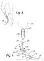
- FIG. 4is a side elevation view of the device in the more flexible support orientation
- FIG. 5is a cross sectional view of the device taken through line 5 — 5 of FIG. 2;
- FIG. 6is a cross sectional view of the device taken through line 6 — 6 of FIG. 2;
- FIG. 7is a cross sectional view of the device taken through line 7 — 7 of FIG. 2;
- FIG. 8is a front elevation view of the device
- FIG. 9is a rear elevation view of the device.
- FIG. 10is a cross sectional view taken through line 10 — 10 of FIG. 9;
- FIG. 11is an exploded perspective view of the device.
- the angularly adjustable reversible prosthetic devicethat forms the basis of the present invention is designated generally by the reference number 10 .
- the device 10comprises in general, a leg unit 11 , a foot unit 12 , and an adjustment unit 13 which permits the leg unit 11 to be reversed and angularly adjusted relative to the foot unit 12 .
- the leg unit 11comprises a leg pylon member 20 which is integrally fabricated from a high density plastic material and includes a generally solid cylindrical upper segment 22 , a generally thin concavo-convex shaped intermediate segment 23 and a generally hollow cylindrical lower segment 24 .
- the upper segment 22is dimensioned to be captively engaged within the tube clamp adapter 101 of a prosthetic socket 100 .
- the longitudinal axis of the generally cylindrical upper segment 22has a vertical orientation
- the curved intermediate segment 23has a generally elongated rectangular cross sectional configuration
- the longitudinal axis of the generally hollow cylindrical lower segment 24has a horizontal orientation.
- the generally hollow cylindrical lower segment 24 of the upper pylon member 20is provided with a pair of elongated slots 25 that are oriented transverse to the longitudinal axis of the lower segment 24 and at least a portion of the external periphery of the lower segment 24 is provided with elongated ridged teeth 26 which are disposed parallel to one another and radially aligned relative to the longitudinal axis of the lower segment 24 .
- the foot unit 12comprises a foot member 40 having an ankle segment 41 , a toe segment 42 , and a heel segment 43 formed integrally with one another from the same high density plastic material that is employed in the fabrication of the upper pylon member 20 .
- the ankle segment 41includes an elongated arcuate ankle socket recess 44 that is dimensioned to slidably engage the hollow cylindrical lower segment 24 of the pylon member 20 when the lower segment 24 is inserted into the ankle socket recess 44 in a lateral fashion.
- the cylindrical lower segment 24is pivotably secured within the ankle socket recess 44 .
- the ankle segmentis further provided with a pair of apertures 45 that are dimensioned to receive the adjustment unit 13 and at least a portion of the interior surface of the arcuate ankle socket recess 44 is provided with elongated ridged teeth 46 that are disposed parallel to one another, radially aligned relative to the longitudinal axis of the arcuate recess 44 and adapted to releasably engage the ridged teeth 26 on the lower segment 23 of the pylon member 20 .
- the toe segment 42 of the foot member 40includes an inboard end 47 which originates as an elongated downwardly curved element extending outwardly from one side of the ankle segment 41 and having a downwardly curved thickened intermediate portion 48 and a generally tapered upwardly curved outboard end 49 .
- the heel segment 43has a generally tapered downwardly curved outboard end 50 and an intermediate transition section 51 which gradually thickens and transforms into an upwardly curved inboard end 52 which merges with the thickened intermediate portion 48 of the toe segment 42 in a generally Y-shaped configuration.
- the outboard end 50 of the heel segment 43extends rearwardly of the ankle segment 41 of the foot member 40 .
- the adjustment unit 13comprises a pair of threaded bolts 60 which are dimensioned to extend through the pair of apertures 45 in the ankle segment 41 of the foot member 40 and the pair of elongated slots 25 in the lower segment 24 of the foot pylon member 20 .
- the inboard end of the threaded bolts 60are adapted to be engaged in a pair of threaded metal sleeves 61 fixedly secured within the apertures 45 in the ankle segment 41 of the foot member 40 .
- this inventiondoes not claim to be the first prosthetic device that employs a concavo-convex leg pylon; however, it is believed to be the first time that a concavo-convex leg pylon has been employed in both a reversible and angularly adjustable fashion relative to the foot portion of the prosthetic device.
- the convex curvature of the intermediate segment 23 of the leg pylon member 20is faced towards the toe segment 42 of the foot member 40 to allow the user to run faster due to the increased stiffness produced by the reverse curvature between the leg pylon member 20 and the toe segment 42 of the foot member 40 .
- the convex curvature of the intermediate segment 23 of the leg pylon member 20is faced towards the heel segment 43 of the foot member 40 to provide greater flexibility to older individuals and moderate walkers due to the increased flexibility produced by the quasi-continuous curvature that exists between the concave surface of the leg pylon member 20 and the toe segment 42 of the foot member 40 .
- the angular adjustment featureallows the user to vary the angular orientation between the leg pylon member 20 and the foot member 40 to raise the heel segment 43 of the foot member 40 upwardly to accommodate footwear having different height heels. This feature is particularly helpful to female amputees who wish to wear high heels as a fashion statement.
- adjustable flexibility/rigidityhas been designed into both the foot member 40 and the pylon leg members 20 of the device 10 .
- the flexibility/rigidity of the foot member 40can be varied in both the toe 42 and heel 43 segments by first removing selected portions of those segments to create elongated voids 70 such as recesses or apertures. The amount of material removed will dictate the amount of increased flexibility that will be created in the affected segments 42 and/or 43 .
- this inventionalso contemplates the use of foot inserts 71 that can be slidably and/or releasably received within the voids 70 to selectively vary the flexibility/rigidity of the segments 42 , 43 both by virtue of the number of inserts 71 employed and by the position of the individual inserts within the respective voids 70 .
- the intermediate segment 23 of the leg pylon member 20is provided with an enlarged central aperture 80 which is dimensioned to receive a plurality of removable vertically oriented rib elements 81 .
- the flexibility/rigidity of the leg pylon member 20is dictated by the number of rib elements 81 that are installed within the aperture 80 at any given time.
Landscapes
- Health & Medical Sciences (AREA)
- Transplantation (AREA)
- Biomedical Technology (AREA)
- Cardiology (AREA)
- Oral & Maxillofacial Surgery (AREA)
- Engineering & Computer Science (AREA)
- Orthopedic Medicine & Surgery (AREA)
- Heart & Thoracic Surgery (AREA)
- Vascular Medicine (AREA)
- Life Sciences & Earth Sciences (AREA)
- Animal Behavior & Ethology (AREA)
- General Health & Medical Sciences (AREA)
- Public Health (AREA)
- Veterinary Medicine (AREA)
- Prostheses (AREA)
Abstract
Description
1. Field of the Invention
The present invention relates to the field of prosthetic devices in general, and in particular to a reversible variable angle prosthetic leg device whose flexibility/rigidity can be selectively varied.
2. Description of Related Art
As can be seen by reference to the following U.S. Pat. Nos. 5,405,410; 5,800,565; 5,888,232; and 5,997,583, the prior art is replete with myriad and diverse prosthetic leg devices. In addition, U.S. Pat. No. 5,464,441 discloses a prosthetic leg device that employs a concavo-convex portion to enhance the flexibility of the prosthetic device.
While all of the aforementioned prior art constructions are more than adequate for the basic purpose and function for which they have been specifically designed, they are uniformly deficient with respect to their failure to provide a simple, efficient, and practical arrangement wherein both the leg and foot portions of the prosthetic leg device are angularly adjustable relative to one another and wherein the rigidity/flexibility of the prosthetic device can be varied in a number of ways.
As most users of prosthetic leg devices are all too well aware, virtually all of the commercially available prosthetic leg devices offer very little in the way of variable rigidity/flexibility for different mobile situations, nor do they feature any angular adjustment between the leg and foot portions of the device to accommodate footwear having different heel heights ranging from flats to short heels for men, as well as flats to high heels for women.
As a consequence of the foregoing situation, there has existed a longstanding need for a new and improved angularly adjustable variable resistance prosthetic leg device which will allow the user to quickly and simply make adjustments to the prosthetic leg device to accommodate the particular needs of the prosthetic wearer at any given time, and the provision of such a device is the stated objective of the present invention.
Briefly stated, the prosthetic leg device that forms the basis of the present invention comprises in general, a leg unit, a foot unit, and an adjustment unit that can be used to vary the angular orientation of the leg unit relative to the foot unit. The invention also includes a number of methods of varying the rigidity/flexibility of both the overall device, as well as specific segments of the leg and foot units.
This invention essentially begins where the concavo-convex arrangement of the Phillips ′441 patent left off in that there is a unique cooperation between the leg and foot units of this invention that permits the leg unit to be quickly and easily reversed 180° relative to the foot unit to convert the prosthetic leg device of this invention from a “walking” prosthetic to a “running” prosthetic.
In addition, the invention allows the leg unit to be angularly adjustable relative to the foot unit, and for both the leg unit and the foot unit to have means for adjusting the rigidity/flexibility of selected portions of each unit.
As will be explained in greater detail further on in the specification, the leg unit includes a leg pylon member having integrally formed upper, intermediate, and lower segments. The upper and lower segments have perpendicularly oriented generally cylindrical configurations and the intermediate segment has a generally thin flat concavo-convex configuration whose reversal relative to the foot unit produces dramatically different results from a rigidity/flexibility standpoint.
Furthermore, the foot unit includes an integrally formed foot member having an ankle segment, a toe segment, and a heel segment. The ankle segment is provided with an elongated arcuate recess that is dimensioned to laterally receive the generally cylindrical lower segment of the leg pylon member such that the concavo-convex intermediate segment of the leg pylon member can be disposed in oppositely facing directions relative to the foot member to produce a generally rigid “walking” configuration or a relative flexible “running” configuration.
As will also be explained in greater detail further on in the specification, the adjustment unit is designed to captively engage the lower segment of the foot pylon member in the arcuate recess of the ankle segment of the foot member at various angular orientations to accommodate footwear having different heel heights. Both the leg unit member and the foot unit have removable elements whose presence or absence will vary the relative rigidity/flexibility of selected portions of those units.
These and other attributes of the invention will become more clear upon a thorough study of the following description of the best mode for carrying out the invention, particularly when reviewed in conjunction with the drawings, wherein:
FIG. 1 is a perspective view of the angularly reversible adjustable prosthetic device oriented to provide more rigid support to the user's leg;
FIG. 2 is a side elevation view of the device in the more rigid support orientation;
FIG. 3 is a perspective view of the angularly adjustable reversible prosthetic device oriented to provide more flexible support to the user's leg;
FIG. 4 is a side elevation view of the device in the more flexible support orientation;
FIG. 5 is a cross sectional view of the device taken throughline 5—5 of FIG. 2;
FIG. 6 is a cross sectional view of the device taken throughline 6—6 of FIG. 2;
FIG. 7 is a cross sectional view of the device taken throughline 7—7 of FIG. 2;
FIG. 8 is a front elevation view of the device;
FIG. 9 is a rear elevation view of the device;
FIG. 10 is a cross sectional view taken throughline 10—10 of FIG. 9; and
FIG. 11 is an exploded perspective view of the device.
As can be seen by reference to the drawings, and in particular to FIG. 1, the angularly adjustable reversible prosthetic device that forms the basis of the present invention is designated generally by thereference number 10. Thedevice 10 comprises in general, a leg unit11, afoot unit 12, and anadjustment unit 13 which permits the leg unit11 to be reversed and angularly adjusted relative to thefoot unit 12. These units will now be described in seriatim fashion.
As shown in FIGS. 1 through 4, and11, the leg unit11 comprises aleg pylon member 20 which is integrally fabricated from a high density plastic material and includes a generally solid cylindricalupper segment 22, a generally thin concavo-convex shapedintermediate segment 23 and a generally hollow cylindricallower segment 24. Theupper segment 22 is dimensioned to be captively engaged within thetube clamp adapter 101 of aprosthetic socket 100.
In addition, the longitudinal axis of the generally cylindricalupper segment 22 has a vertical orientation, the curvedintermediate segment 23 has a generally elongated rectangular cross sectional configuration, and the longitudinal axis of the generally hollow cylindricallower segment 24 has a horizontal orientation.
As can best be seen by reference to FIG. 11, the generally hollow cylindricallower segment 24 of theupper pylon member 20 is provided with a pair ofelongated slots 25 that are oriented transverse to the longitudinal axis of thelower segment 24 and at least a portion of the external periphery of thelower segment 24 is provided with elongatedridged teeth 26 which are disposed parallel to one another and radially aligned relative to the longitudinal axis of thelower segment 24.
Still referring to FIG. 11, it can be seen that thefoot unit 12 comprises afoot member 40 having anankle segment 41, atoe segment 42, and aheel segment 43 formed integrally with one another from the same high density plastic material that is employed in the fabrication of theupper pylon member 20.
Theankle segment 41 includes an elongated arcuate ankle socket recess44 that is dimensioned to slidably engage the hollow cylindricallower segment 24 of thepylon member 20 when thelower segment 24 is inserted into the ankle socket recess44 in a lateral fashion. The cylindricallower segment 24 is pivotably secured within theankle socket recess 44.
In addition, the ankle segment is further provided with a pair of apertures45 that are dimensioned to receive theadjustment unit 13 and at least a portion of the interior surface of the arcuateankle socket recess 44 is provided with elongatedridged teeth 46 that are disposed parallel to one another, radially aligned relative to the longitudinal axis of thearcuate recess 44 and adapted to releasably engage theridged teeth 26 on thelower segment 23 of thepylon member 20.
As shown in FIG. 4, thetoe segment 42 of thefoot member 40 includes aninboard end 47 which originates as an elongated downwardly curved element extending outwardly from one side of theankle segment 41 and having a downwardly curved thickenedintermediate portion 48 and a generally tapered upwardlycurved outboard end 49. In addition, theheel segment 43 has a generally tapered downwardly curvedoutboard end 50 and anintermediate transition section 51 which gradually thickens and transforms into an upwardly curvedinboard end 52 which merges with the thickenedintermediate portion 48 of thetoe segment 42 in a generally Y-shaped configuration. Theoutboard end 50 of theheel segment 43 extends rearwardly of theankle segment 41 of thefoot member 40.
As can best be appreciated by reference to FIGS. 2,4,9, and11, theadjustment unit 13 comprises a pair of threadedbolts 60 which are dimensioned to extend through the pair of apertures45 in theankle segment 41 of thefoot member 40 and the pair ofelongated slots 25 in thelower segment 24 of thefoot pylon member 20. The inboard end of the threadedbolts 60 are adapted to be engaged in a pair of threadedmetal sleeves 61 fixedly secured within the apertures45 in theankle segment 41 of thefoot member 40.
As was mentioned previously in the specification, this invention does not claim to be the first prosthetic device that employs a concavo-convex leg pylon; however, it is believed to be the first time that a concavo-convex leg pylon has been employed in both a reversible and angularly adjustable fashion relative to the foot portion of the prosthetic device.
In the orientation depicted in FIGS. 1 and 2, the convex curvature of theintermediate segment 23 of theleg pylon member 20 is faced towards thetoe segment 42 of thefoot member 40 to allow the user to run faster due to the increased stiffness produced by the reverse curvature between theleg pylon member 20 and thetoe segment 42 of thefoot member 40.
Furthermore, in the orientation depicted in FIGS. 3 and 4, the convex curvature of theintermediate segment 23 of theleg pylon member 20 is faced towards theheel segment 43 of thefoot member 40 to provide greater flexibility to older individuals and moderate walkers due to the increased flexibility produced by the quasi-continuous curvature that exists between the concave surface of theleg pylon member 20 and thetoe segment 42 of thefoot member 40.
As can also be appreciated by reference to FIGS. 3 and 4, the angular adjustment feature allows the user to vary the angular orientation between theleg pylon member 20 and thefoot member 40 to raise theheel segment 43 of thefoot member 40 upwardly to accommodate footwear having different height heels. This feature is particularly helpful to female amputees who wish to wear high heels as a fashion statement.
Turning now to FIGS. 5 through 10, it can be seen that adjustable flexibility/rigidity has been designed into both thefoot member 40 and thepylon leg members 20 of thedevice 10.
As shown in FIGS. 5 through 7, the flexibility/rigidity of thefoot member 40 can be varied in both thetoe 42 andheel 43 segments by first removing selected portions of those segments to createelongated voids 70 such as recesses or apertures. The amount of material removed will dictate the amount of increased flexibility that will be created in the affectedsegments 42 and/or43.
Furthermore, this invention also contemplates the use offoot inserts 71 that can be slidably and/or releasably received within thevoids 70 to selectively vary the flexibility/rigidity of thesegments inserts 71 employed and by the position of the individual inserts within therespective voids 70.
Turning now to FIGS. 8 through 10, it can be seen that theintermediate segment 23 of theleg pylon member 20 is provided with an enlargedcentral aperture 80 which is dimensioned to receive a plurality of removable vertically orientedrib elements 81. The flexibility/rigidity of theleg pylon member 20 is dictated by the number ofrib elements 81 that are installed within theaperture 80 at any given time.
Although only an exemplary embodiment of the invention has been described in detail above, those skilled in the art will readily appreciate that many modifications are possible without materially departing from the novel teachings and advantages of this invention. Accordingly, all such modifications are intended to be included within the scope of this invention as defined in the following claims.
Having thereby described the subject matter of the present invention, it should be apparent that many substitutions, modifications, and variations of the invention are possible in light of the above teachings. It is therefore to be understood that the invention as taught and described herein is only to be limited to the extent of the breadth and scope of the appended claims.
Claims (20)
1. An angularly adjustable reversible prosthetic leg device for use with a prosthetic socket having a tube clamp adapter wherein the device comprises:
a leg unit including a leg pylon member having an upper segment adapted to be captively engaged by said tube clamp adapter, an intermediate segment, and a lower segment;
a foot unit including a foot member having an ankle segment, a toe segment, and a heel segment wherein, the foot member is further provided with a recess extending downwardly through the ankle segment and dimensioned to slidably engage the lower segment of the leg pylon member in a lateral fashion; and,
means for captively securing the leg pylon member at a desired angular orientation about a horizontal axis relative to the foot member.
2. The device as inclaim 1 wherein said upper segment has a generally cylindrical configuration dimensioned to be received in the tube clamp adapter.
3. The device as inclaim 2 wherein said intermediate segment has a generally thin flat concavo-convex configuration.
4. The device as inclaim 3 wherein the recess in the ankle segment is further dimensioned to receive the lower segment of the leg pylon member in a first position and in a second oppositely facing position.
5. The device as inclaim 3 wherein the concavo-convex intermediate segment of the leg pylon member is provided with an enlarged aperture having a plurality of removable rib elements.
6. The device as inclaim 1 wherein the upper, intermediate and lower segments are fabricated integrally with one another.
7. The device as inclaim 6 wherein the ankle, toe, and heel segments are formed integrally with one another.
8. The device as inclaim 1 wherein the ankle, toe, and heel segments are formed integrally with one another.
9. The device as inclaim 1 wherein the lower segment of the leg pylon member has a generally cylindrical configuration and the ankle segment of the foot member has an arcuate recess dimensioned to pivotally receive the generally cylindrical configuration.
10. The device as inclaim 9 wherein both the lower segment of the leg pylon member and said arcuate recess are provided with elongated ridged teeth that are at least temporarily engageable with one another.
11. The device as inclaim 9 wherein the generally cylindrical lower segment of the leg pylon member is provided with a pair of elongated slots and the ankle segment of the foot member is provided with a pair of apertures that extend across said arcuate recess and are alignable with said pair of elongated slots.
12. The device as inclaim 11 further comprising:
a pair of bolts dimensioned to be received through said pair of apertures in the ankle segment of the foot member and the pair of elongated slots in the lower segment of the leg pylon member.
13. The device as inclaim 1 further comprising:
means for adjusting the flexibility/rigidity of the leg pylon member.
14. The device as inclaim 13 further comprising:
means for adjusting the flexibility/rigidity of the foot member.
15. The device as inclaim 1 wherein the intermediate segment of the leg pylon member is provided with a plurality of removably vertical rib elements for varying the flexibility/rigidity of the leg pylon member.
16. The device as inclaim 1 further comprising:
means for adjusting the flexibility/rigidity of the foot member.
17. The device as inclaim 16 wherein said means for adjusting the flexibility/rigidity of the foot member includes at least in part at least one elongated void formed in a selected portion of said foot member.
18. The device as inclaim 17 wherein said means for adjusting the flexibility/rigidity of the foot member further includes at least one insert dimensioned to be removably received in said at least one void.
19. The device as inclaim 18 wherein said at least one insert is adapted to be slidably received in said at least one void.
20. The device as inclaim 1 wherein said selected portion of the foot member comprises the ankle segment.
Priority Applications (1)
| Application Number | Priority Date | Filing Date | Title |
|---|---|---|---|
| US09/621,297US6402790B1 (en) | 2000-07-20 | 2000-07-20 | Angularly adjustable reversible prosthetic device |
Applications Claiming Priority (1)
| Application Number | Priority Date | Filing Date | Title |
|---|---|---|---|
| US09/621,297US6402790B1 (en) | 2000-07-20 | 2000-07-20 | Angularly adjustable reversible prosthetic device |
Publications (1)
| Publication Number | Publication Date |
|---|---|
| US6402790B1true US6402790B1 (en) | 2002-06-11 |
Family
ID=24489583
Family Applications (1)
| Application Number | Title | Priority Date | Filing Date |
|---|---|---|---|
| US09/621,297Expired - LifetimeUS6402790B1 (en) | 2000-07-20 | 2000-07-20 | Angularly adjustable reversible prosthetic device |
Country Status (1)
| Country | Link |
|---|---|
| US (1) | US6402790B1 (en) |
Cited By (61)
| Publication number | Priority date | Publication date | Assignee | Title |
|---|---|---|---|---|
| US20030028256A1 (en)* | 2001-03-30 | 2003-02-06 | Townsend Barry W. | Prosthetic foot with tunable performance |
| EP1374810A1 (en)* | 2002-06-28 | 2004-01-02 | Tamarack Habilitation Technologies, Inc. | Adjustable mounting housing for prosthetic ankle flexure joint |
| US6702859B1 (en)* | 2002-08-22 | 2004-03-09 | Aldo A. Laghi | Dynamic prosthetic foot with multiple load points and anterior/posterior upper sections |
| US20040117036A1 (en)* | 2001-03-30 | 2004-06-17 | Townsend Barry W | Prosthetic foot with tunable performance |
| US6764522B1 (en)* | 2003-05-08 | 2004-07-20 | Teh Lin Prosthetic & Orthopaedic Inc. | Prosthetic foot |
| US6793683B1 (en)* | 2002-08-22 | 2004-09-21 | Aldo A. Laghi | Prosthetic foot with medial/lateral stabilization |
| US20040186592A1 (en)* | 2001-03-30 | 2004-09-23 | Townsend Barry W. | Prosthetic foot with tunable performance |
| US20040199265A1 (en)* | 2000-12-22 | 2004-10-07 | Townsend Barry W. | Prosthetic foot |
| US20040225376A1 (en)* | 2000-12-22 | 2004-11-11 | Townsend Barry W. | Prosthetic foot |
| US20050038524A1 (en)* | 2003-08-15 | 2005-02-17 | Jonsson Orn Ingvi | Low profile prosthetic foot |
| US20050049721A1 (en)* | 2003-08-29 | 2005-03-03 | Sulprizio Michael Scott | Wideband CDMA mobile device initial frequency offset acquisition |
| US20050085926A1 (en)* | 2003-10-21 | 2005-04-21 | General Partner Of The Roland J. Christensen Family Limited Partnership | Prosthetic foot with an adjustable ankle and method |
| US20050171618A1 (en)* | 2000-06-30 | 2005-08-04 | Christensen Roland J. | Prosthetic foot with energy transfer including variable orifice |
| US20050177250A1 (en)* | 2001-03-30 | 2005-08-11 | Townsend Barry W. | Prosthetic foot with tunable performance |
| US20050187640A1 (en)* | 2004-02-20 | 2005-08-25 | Roland J. Christensen | Prosthetic foot with cam |
| US20050216098A1 (en)* | 2000-06-30 | 2005-09-29 | Roland J. Christensen | Variable resistance cell |
| US20050267603A1 (en)* | 2004-05-28 | 2005-12-01 | Lecomte Christophe G | Foot prosthesis with resilient multi-axial ankle |
| US20060041321A1 (en)* | 2003-10-21 | 2006-02-23 | Christensen Roland J | Prosthetic foot with an adjustable ankle and method |
| US20060058893A1 (en)* | 2004-05-28 | 2006-03-16 | Clausen Arinbjorn V | Method of measuring the performance of a prosthetic foot |
| US20060178754A1 (en)* | 2001-03-30 | 2006-08-10 | Townsend Barry W | Prosthetic foot with tunable performance and improved vertical load/shock absorption |
| US20060229736A1 (en)* | 2000-06-30 | 2006-10-12 | Christensen Roland J | Prosthetic foot with energy transfer |
| US20060241783A1 (en)* | 2000-06-30 | 2006-10-26 | Christensen Roland J | Variable resistance cell |
| US20070213841A1 (en)* | 2001-03-30 | 2007-09-13 | Townsend Barry W | Prosthetic foot with tunable performance |
| US20070213840A1 (en)* | 2003-09-30 | 2007-09-13 | Townsend Barry W | Prosthetic Foot with Tunable Performance |
| US20070219643A1 (en)* | 2004-04-01 | 2007-09-20 | Townsend Barry W | Prosthetic Foot With Tunable Performance |
| US20080033578A1 (en)* | 2006-08-03 | 2008-02-07 | Christensen Roland J | Prosthetic foot with variable medial/lateral stiffness |
| US7374578B2 (en) | 2001-03-30 | 2008-05-20 | Bioquest Prosthetics, Llc | Prosthetic foot with tunable performance |
| US20080167731A1 (en)* | 2006-12-06 | 2008-07-10 | Christensen Roland J | Prosthetic foot with longer upper forefoot and shorter lower forefoot |
| US20080183301A1 (en)* | 2000-06-30 | 2008-07-31 | Christensen Roland J | Prosthetic foot with energy transfer |
| US20080188951A1 (en)* | 2007-01-30 | 2008-08-07 | Christensen Roland J | Prosthetic foot with variable medial/lateral stiffness |
| US7462201B2 (en) | 2003-10-21 | 2008-12-09 | Freedom Innovations, Llc | Prosthetic foot with an adjustable ankle and method |
| US20090105845A1 (en)* | 2007-10-19 | 2009-04-23 | Curtis Michael J | Prosthetic foot with a processor to manage energy return of adjustable heel and keel springs |
| US7611543B2 (en) | 2001-03-30 | 2009-11-03 | Bioquest Prosthetics, Llc | Prosthetic foot with tunable performance |
| US20100004757A1 (en)* | 2008-07-01 | 2010-01-07 | Ossur Hf | Smooth rollover insole for prosthetic foot |
| US20100030344A1 (en)* | 2008-07-31 | 2010-02-04 | Northwestern University | Prosthetic foot with adjustable flat region |
| US7763082B1 (en)* | 2007-10-19 | 2010-07-27 | American Prosthetic Components, Inc. | Prosthetic foot with heel and keel springs |
| US7794506B2 (en) | 2007-09-18 | 2010-09-14 | Freedom Innovations, Llc | Multi-axial prosthetic ankle |
| US20110071650A1 (en)* | 2003-09-30 | 2011-03-24 | Townsend Barry W | Resilient prosthetic and orthotic components which incorporate a plurality of sagittally oriented struts |
| US20110208323A1 (en)* | 2010-02-23 | 2011-08-25 | Ossur Hf | Metatarsal joint shape for prosthetic foot and control mechanism and system for same |
| US20110213471A1 (en)* | 2010-02-26 | 2011-09-01 | össur hf | Prosthetic foot with a curved split |
| US8034121B2 (en) | 2008-04-18 | 2011-10-11 | Freedom Innovations, Llc | Prosthetic foot with two leaf-springs joined at heel and toe |
| US8236062B2 (en) | 2001-03-30 | 2012-08-07 | Bioquest Prosthetics Llc | Prosthetic foot with tunable performance |
| US8500825B2 (en) | 2010-06-29 | 2013-08-06 | Freedom Innovations, Llc | Prosthetic foot with floating forefoot keel |
| US8961618B2 (en) | 2011-12-29 | 2015-02-24 | össur hf | Prosthetic foot with resilient heel |
| US9028559B2 (en) | 2011-09-26 | 2015-05-12 | össur hf | Frictionless vertical suspension mechanism for prosthetic feet |
| US9439786B2 (en) | 2012-08-01 | 2016-09-13 | össur hf | Prosthetic ankle module |
| USD795433S1 (en) | 2015-06-30 | 2017-08-22 | Össur Iceland Ehf | Prosthetic foot cover |
| USD797292S1 (en) | 2014-06-30 | 2017-09-12 | össur hf | Prosthetic foot plate |
| US10034783B1 (en)* | 2013-12-17 | 2018-07-31 | University Of South Florida | Adjustable prosthetic ankles |
| US10034782B2 (en) | 2014-09-19 | 2018-07-31 | össur hf | Variable stiffness prosthetic foot |
| US10251762B2 (en) | 2011-05-03 | 2019-04-09 | Victhom Laboratory Inc. | Impedance simulating motion controller for orthotic and prosthetic applications |
| CN111249042A (en)* | 2020-03-04 | 2020-06-09 | 北京工道风行智能技术有限公司 | Stepless adjustable heel storage feet |
| US10821007B2 (en) | 2016-12-01 | 2020-11-03 | Össur Iceland Ehf | Prosthetic feet having heel height adjustability |
| USD915596S1 (en) | 2018-04-10 | 2021-04-06 | Össur Iceland Ehf | Prosthetic foot with tapered fasteners |
| US10980648B1 (en) | 2017-09-15 | 2021-04-20 | Össur Iceland Ehf | Variable stiffness mechanism and limb support device incorporating the same |
| US11446164B1 (en) | 2017-09-15 | 2022-09-20 | Össur Iceland Ehf | Variable stiffness mechanisms |
| US11931271B2 (en) | 2021-02-01 | 2024-03-19 | Liberating Technologies, Inc. | Prosthetic foot with switchable walking and jogging modes |
| US12201537B2 (en) | 2020-11-30 | 2025-01-21 | Össur Iceland Ehf | Prosthetic foot with layers of fibrous material |
| US12263102B2 (en) | 2020-08-28 | 2025-04-01 | Össur Iceland Ehf | Prosthetic foot with variable stiffness ankle |
| WO2025165233A1 (en)* | 2024-05-08 | 2025-08-07 | Dutch Prosthetics B.V. | Modular foot prosthesis system |
| US12414867B1 (en) | 2018-06-01 | 2025-09-16 | Össur Iceland Ehf | Prosthetic feet with increased flexibility to accommodate different heel heights |
Citations (7)
| Publication number | Priority date | Publication date | Assignee | Title |
|---|---|---|---|---|
| US5405410A (en) | 1992-08-12 | 1995-04-11 | Ohio Willow Wood Company | Adjustable lower limb prosthesis having conical support |
| US5464441A (en)* | 1990-01-12 | 1995-11-07 | Phillips; Van L. | Prosthetic leg |
| US5549711A (en)* | 1993-09-30 | 1996-08-27 | M+Ind (Model + Instrument Development) | Prosthetic foot and keel therefor having progressive stiffening under increasing load |
| US5800565A (en) | 1994-05-25 | 1998-09-01 | Biedermann Motech Gmbh | Leg prosthesis with quick exchange and displacement adjustment connections |
| US5800564A (en)* | 1995-09-18 | 1998-09-01 | Gelineau; Roger | Ankle prosthesis with angle adjustment |
| US5888232A (en) | 1994-11-29 | 1999-03-30 | Taylor; Douglas A. | Ultralight modular quick-adjusting connector |
| US5997583A (en)* | 1996-10-10 | 1999-12-07 | Chas. A. Blatchford & Sons Limited | Lower limb prosthesis and a shin component for the prosthesis |
- 2000
- 2000-07-20USUS09/621,297patent/US6402790B1/ennot_activeExpired - Lifetime
Patent Citations (7)
| Publication number | Priority date | Publication date | Assignee | Title |
|---|---|---|---|---|
| US5464441A (en)* | 1990-01-12 | 1995-11-07 | Phillips; Van L. | Prosthetic leg |
| US5405410A (en) | 1992-08-12 | 1995-04-11 | Ohio Willow Wood Company | Adjustable lower limb prosthesis having conical support |
| US5549711A (en)* | 1993-09-30 | 1996-08-27 | M+Ind (Model + Instrument Development) | Prosthetic foot and keel therefor having progressive stiffening under increasing load |
| US5800565A (en) | 1994-05-25 | 1998-09-01 | Biedermann Motech Gmbh | Leg prosthesis with quick exchange and displacement adjustment connections |
| US5888232A (en) | 1994-11-29 | 1999-03-30 | Taylor; Douglas A. | Ultralight modular quick-adjusting connector |
| US5800564A (en)* | 1995-09-18 | 1998-09-01 | Gelineau; Roger | Ankle prosthesis with angle adjustment |
| US5997583A (en)* | 1996-10-10 | 1999-12-07 | Chas. A. Blatchford & Sons Limited | Lower limb prosthesis and a shin component for the prosthesis |
Cited By (128)
| Publication number | Priority date | Publication date | Assignee | Title |
|---|---|---|---|---|
| US20050171618A1 (en)* | 2000-06-30 | 2005-08-04 | Christensen Roland J. | Prosthetic foot with energy transfer including variable orifice |
| US7686848B2 (en) | 2000-06-30 | 2010-03-30 | Freedom Innovations, Llc | Prosthetic foot with energy transfer |
| US7572299B2 (en) | 2000-06-30 | 2009-08-11 | Freedom Innovations, Llc | Prosthetic foot with energy transfer |
| US20080183301A1 (en)* | 2000-06-30 | 2008-07-31 | Christensen Roland J | Prosthetic foot with energy transfer |
| US7341603B2 (en) | 2000-06-30 | 2008-03-11 | Applied Composite Technology, Inc. | Prosthetic foot with energy transfer including variable orifice |
| US20060241783A1 (en)* | 2000-06-30 | 2006-10-26 | Christensen Roland J | Variable resistance cell |
| US20060229736A1 (en)* | 2000-06-30 | 2006-10-12 | Christensen Roland J | Prosthetic foot with energy transfer |
| US20050216098A1 (en)* | 2000-06-30 | 2005-09-29 | Roland J. Christensen | Variable resistance cell |
| US7108723B2 (en) | 2000-12-22 | 2006-09-19 | Townsend Barry W | Prosthetic foot |
| US20040199265A1 (en)* | 2000-12-22 | 2004-10-07 | Townsend Barry W. | Prosthetic foot |
| US20040225376A1 (en)* | 2000-12-22 | 2004-11-11 | Townsend Barry W. | Prosthetic foot |
| US6936074B2 (en) | 2000-12-22 | 2005-08-30 | Barry W. Townsend | Prosthetic foot |
| US7708784B2 (en) | 2001-03-30 | 2010-05-04 | Bioquest Prosthetics, Llc | Prosthetic foot with tunable performance |
| US20030191540A1 (en)* | 2001-03-30 | 2003-10-09 | Townsend Barry W. | Prosthetic foot with tunable performance |
| US20030028256A1 (en)* | 2001-03-30 | 2003-02-06 | Townsend Barry W. | Prosthetic foot with tunable performance |
| US8236062B2 (en) | 2001-03-30 | 2012-08-07 | Bioquest Prosthetics Llc | Prosthetic foot with tunable performance |
| US20050177250A1 (en)* | 2001-03-30 | 2005-08-11 | Townsend Barry W. | Prosthetic foot with tunable performance |
| US7374578B2 (en) | 2001-03-30 | 2008-05-20 | Bioquest Prosthetics, Llc | Prosthetic foot with tunable performance |
| US7364593B2 (en) | 2001-03-30 | 2008-04-29 | Bioquest Prosthetics Llc | Prosthetic foot with tunable performance |
| US20040117036A1 (en)* | 2001-03-30 | 2004-06-17 | Townsend Barry W | Prosthetic foot with tunable performance |
| US20080183302A1 (en)* | 2001-03-30 | 2008-07-31 | Townsend Barry W | Prosthetic foot with tunable performance |
| US7611543B2 (en) | 2001-03-30 | 2009-11-03 | Bioquest Prosthetics, Llc | Prosthetic foot with tunable performance |
| US7410503B2 (en) | 2001-03-30 | 2008-08-12 | Bioquest Prosthetics Llc | Prosthetic foot with tunable performance |
| US7429272B2 (en) | 2001-03-30 | 2008-09-30 | Bioquest Prosthetics Llc | Prosthetic foot with tunable performance |
| US7578852B2 (en)* | 2001-03-30 | 2009-08-25 | Bioquest Prosthetics, Llc | Prosthetic foot with tunable performance and improved vertical load/shock absorption |
| US20070213841A1 (en)* | 2001-03-30 | 2007-09-13 | Townsend Barry W | Prosthetic foot with tunable performance |
| US20060178754A1 (en)* | 2001-03-30 | 2006-08-10 | Townsend Barry W | Prosthetic foot with tunable performance and improved vertical load/shock absorption |
| US20040186592A1 (en)* | 2001-03-30 | 2004-09-23 | Townsend Barry W. | Prosthetic foot with tunable performance |
| US7226485B2 (en)* | 2001-03-30 | 2007-06-05 | Bioquest Prosthetics, Llc | Prosthetic foot with tunable performance |
| US7507259B2 (en) | 2001-03-30 | 2009-03-24 | Bioquest Prosthetics, Llc | Prosthetic foot with tunable performance |
| US7211115B2 (en) | 2001-03-30 | 2007-05-01 | Townsend Barry W | Prosthetic foot with tunable performance |
| US6824523B2 (en) | 2002-06-28 | 2004-11-30 | Tamarack Habilitation Technologies, Inc. | Adjustable mounting housing for orthotic ankle flexure joint |
| EP1374810A1 (en)* | 2002-06-28 | 2004-01-02 | Tamarack Habilitation Technologies, Inc. | Adjustable mounting housing for prosthetic ankle flexure joint |
| US6793683B1 (en)* | 2002-08-22 | 2004-09-21 | Aldo A. Laghi | Prosthetic foot with medial/lateral stabilization |
| US6702859B1 (en)* | 2002-08-22 | 2004-03-09 | Aldo A. Laghi | Dynamic prosthetic foot with multiple load points and anterior/posterior upper sections |
| US6875240B1 (en)* | 2002-08-22 | 2005-04-05 | Dynamic prosthetic foot with multiple load points and anterior/posterior upper sections | |
| US6764522B1 (en)* | 2003-05-08 | 2004-07-20 | Teh Lin Prosthetic & Orthopaedic Inc. | Prosthetic foot |
| US20050038524A1 (en)* | 2003-08-15 | 2005-02-17 | Jonsson Orn Ingvi | Low profile prosthetic foot |
| US8377146B2 (en) | 2003-08-15 | 2013-02-19 | Ossur Hf | Low profile prosthetic foot |
| US8007544B2 (en) | 2003-08-15 | 2011-08-30 | Ossur Hf | Low profile prosthetic foot |
| US9579220B2 (en) | 2003-08-15 | 2017-02-28 | össur hf | Low profile prosthetic foot |
| US8377144B2 (en) | 2003-08-15 | 2013-02-19 | Ossur Hf | Low profile prosthetic foot |
| US8858649B2 (en) | 2003-08-15 | 2014-10-14 | össur hf | Low profile prosthetic foot |
| US20050049721A1 (en)* | 2003-08-29 | 2005-03-03 | Sulprizio Michael Scott | Wideband CDMA mobile device initial frequency offset acquisition |
| US6942704B2 (en) | 2003-08-29 | 2005-09-13 | S & L, Inc. | Prosthetic foot |
| US8070829B2 (en) | 2003-09-30 | 2011-12-06 | Bioquest Prosthetics Llc | Prosthetic foot with tunable performance |
| US20070213840A1 (en)* | 2003-09-30 | 2007-09-13 | Townsend Barry W | Prosthetic Foot with Tunable Performance |
| US8574314B2 (en) | 2003-09-30 | 2013-11-05 | Bioquest Prosthetics Llc | Resilient prosthetic and orthotic components which incorporate a plurality of sagittally oriented struts |
| US20110071650A1 (en)* | 2003-09-30 | 2011-03-24 | Townsend Barry W | Resilient prosthetic and orthotic components which incorporate a plurality of sagittally oriented struts |
| US8808395B2 (en) | 2003-09-30 | 2014-08-19 | Bioquest Prosthetics, LLC. | Resilient prosthetic and orthotic components which incorporate a plurality of sagittally oriented struts |
| US6966933B2 (en) | 2003-10-21 | 2005-11-22 | Roland J. Christensen, As Operating Manager Of Rjc Development, Lc, General Partner Of The Roland J. Christensen Family Limited Partnership | Prosthetic foot with an adjustable ankle and method |
| US20050085926A1 (en)* | 2003-10-21 | 2005-04-21 | General Partner Of The Roland J. Christensen Family Limited Partnership | Prosthetic foot with an adjustable ankle and method |
| US7462201B2 (en) | 2003-10-21 | 2008-12-09 | Freedom Innovations, Llc | Prosthetic foot with an adjustable ankle and method |
| US7520904B2 (en) | 2003-10-21 | 2009-04-21 | Freedom Innovations, Llc | Prosthetic foot with an adjustable ankle and method |
| US20060041321A1 (en)* | 2003-10-21 | 2006-02-23 | Christensen Roland J | Prosthetic foot with an adjustable ankle and method |
| US7172630B2 (en) | 2004-02-20 | 2007-02-06 | Roland J. Christensen, As Operating Manager Of Rjc Development, Lc, General Partner Of The Roland J. Christensen Family Limited Partnership | Prosthetic foot with cam |
| US20050187640A1 (en)* | 2004-02-20 | 2005-08-25 | Roland J. Christensen | Prosthetic foot with cam |
| US7955399B2 (en) | 2004-04-01 | 2011-06-07 | Bioquest Prosthetics, Llc | Prosthetic foot with tunable performance |
| JP2007530238A (en)* | 2004-04-01 | 2007-11-01 | ダブリュ タウンゼンド、バリー | Adjustable artificial leg |
| US20070219643A1 (en)* | 2004-04-01 | 2007-09-20 | Townsend Barry W | Prosthetic Foot With Tunable Performance |
| US20050267602A1 (en)* | 2004-05-28 | 2005-12-01 | Clausen Arinbjorn V | Foot prosthesis with resilient multi-axial ankle |
| US9668887B2 (en) | 2004-05-28 | 2017-06-06 | össur hf | Foot prosthesis with resilient multi-axial ankle |
| US20050267603A1 (en)* | 2004-05-28 | 2005-12-01 | Lecomte Christophe G | Foot prosthesis with resilient multi-axial ankle |
| US20090306792A1 (en)* | 2004-05-28 | 2009-12-10 | Õssur hf. | Foot prosthesis with resilient multi-axial ankle |
| US7846213B2 (en)* | 2004-05-28 | 2010-12-07 | össur hf. | Foot prosthesis with resilient multi-axial ankle |
| US20060058893A1 (en)* | 2004-05-28 | 2006-03-16 | Clausen Arinbjorn V | Method of measuring the performance of a prosthetic foot |
| US7347877B2 (en)* | 2004-05-28 | 2008-03-25 | össur hf | Foot prosthesis with resilient multi-axial ankle |
| US20070106395A9 (en)* | 2004-05-28 | 2007-05-10 | Clausen Arinbjorn V | Foot prosthesis with resilient multi-axial ankle |
| US20090293641A1 (en)* | 2004-05-28 | 2009-12-03 | Clausen Arinbjoern V | Method of measuring the performance of a prosthetic foot |
| US20090287315A1 (en)* | 2004-05-28 | 2009-11-19 | össur hf. | Foot prosthesis with resilient multi-axial ankle |
| US8025699B2 (en) | 2004-05-28 | 2011-09-27 | össur hf | Foot prosthesis with resilient multi-axial ankle |
| US7891258B2 (en) | 2004-05-28 | 2011-02-22 | össur hf | Method of measuring the performance of a prosthetic foot |
| US9132022B2 (en) | 2004-05-28 | 2015-09-15 | össur hf | Foot prosthesis with resilient multi-axial ankle |
| US7581454B2 (en) | 2004-05-28 | 2009-09-01 | össur hf | Method of measuring the performance of a prosthetic foot |
| US7998221B2 (en)* | 2004-05-28 | 2011-08-16 | össur hf | Foot prosthesis with resilient multi-axial ankle |
| DE112005002613B4 (en) | 2004-10-20 | 2018-05-30 | Freedom Innovations,LLC (n.d.Ges.d.Staates Delaware) | Foot prosthesis with adjustable ankle and corresponding procedure |
| US7618464B2 (en) | 2006-08-03 | 2009-11-17 | Freedom Innovations, Llc | Prosthetic foot with variable medial/lateral stiffness |
| US20080033578A1 (en)* | 2006-08-03 | 2008-02-07 | Christensen Roland J | Prosthetic foot with variable medial/lateral stiffness |
| US7824446B2 (en) | 2006-12-06 | 2010-11-02 | Freedom Innovations, Llc | Prosthetic foot with longer upper forefoot and shorter lower forefoot |
| US20080167731A1 (en)* | 2006-12-06 | 2008-07-10 | Christensen Roland J | Prosthetic foot with longer upper forefoot and shorter lower forefoot |
| US20080188951A1 (en)* | 2007-01-30 | 2008-08-07 | Christensen Roland J | Prosthetic foot with variable medial/lateral stiffness |
| US7727285B2 (en) | 2007-01-30 | 2010-06-01 | Freedom Innovations, Llc | Prosthetic foot with variable medial/lateral stiffness |
| US7794506B2 (en) | 2007-09-18 | 2010-09-14 | Freedom Innovations, Llc | Multi-axial prosthetic ankle |
| US20090105845A1 (en)* | 2007-10-19 | 2009-04-23 | Curtis Michael J | Prosthetic foot with a processor to manage energy return of adjustable heel and keel springs |
| US7766974B2 (en)* | 2007-10-19 | 2010-08-03 | American Prosthetic Components, Inc. | Prosthetic foot with a processor to manage energy return of adjustable heel and keel springs |
| US7763082B1 (en)* | 2007-10-19 | 2010-07-27 | American Prosthetic Components, Inc. | Prosthetic foot with heel and keel springs |
| US8034121B2 (en) | 2008-04-18 | 2011-10-11 | Freedom Innovations, Llc | Prosthetic foot with two leaf-springs joined at heel and toe |
| US20100004757A1 (en)* | 2008-07-01 | 2010-01-07 | Ossur Hf | Smooth rollover insole for prosthetic foot |
| US9168158B2 (en) | 2008-07-01 | 2015-10-27 | össur hf | Smooth rollover insole for prosthetic foot |
| US8685109B2 (en) | 2008-07-01 | 2014-04-01 | össur hf | Smooth rollover insole for prosthetic foot |
| US20100030344A1 (en)* | 2008-07-31 | 2010-02-04 | Northwestern University | Prosthetic foot with adjustable flat region |
| US8574313B2 (en) | 2010-02-23 | 2013-11-05 | össur hf | Metatarsal joint shape for prosthetic foot and control mechanism and system for same |
| US20110208323A1 (en)* | 2010-02-23 | 2011-08-25 | Ossur Hf | Metatarsal joint shape for prosthetic foot and control mechanism and system for same |
| US9427338B2 (en) | 2010-02-23 | 2016-08-30 | össur hf | Metatarsal joint shape for prosthetic foot and control mechanism and system for same |
| US8486156B2 (en) | 2010-02-26 | 2013-07-16 | össur hf | Prosthetic foot with a curved split |
| US20110213471A1 (en)* | 2010-02-26 | 2011-09-01 | össur hf | Prosthetic foot with a curved split |
| US8500825B2 (en) | 2010-06-29 | 2013-08-06 | Freedom Innovations, Llc | Prosthetic foot with floating forefoot keel |
| US11185429B2 (en) | 2011-05-03 | 2021-11-30 | Victhom Laboratory Inc. | Impedance simulating motion controller for orthotic and prosthetic applications |
| US10251762B2 (en) | 2011-05-03 | 2019-04-09 | Victhom Laboratory Inc. | Impedance simulating motion controller for orthotic and prosthetic applications |
| US9028559B2 (en) | 2011-09-26 | 2015-05-12 | össur hf | Frictionless vertical suspension mechanism for prosthetic feet |
| US11478364B2 (en) | 2011-09-26 | 2022-10-25 | Össur Iceland Ehf | Frictionless vertical suspension mechanism for prosthetic feet |
| US10758377B2 (en) | 2011-09-26 | 2020-09-01 | Össur Iceland Ehf | Frictionless vertical suspension mechanism for prosthetic feet |
| US20150250623A1 (en)* | 2011-09-26 | 2015-09-10 | össur hf | Frictionless vertical suspension mechanism for prosthetic feet |
| US9999523B2 (en)* | 2011-09-26 | 2018-06-19 | össur hf | Frictionless vertical suspension mechanism for prosthetic feet |
| US8961618B2 (en) | 2011-12-29 | 2015-02-24 | össur hf | Prosthetic foot with resilient heel |
| US9439786B2 (en) | 2012-08-01 | 2016-09-13 | össur hf | Prosthetic ankle module |
| US10342680B2 (en) | 2012-08-01 | 2019-07-09 | Ossur Iceland Ehf | Prosthetic ankle module |
| US10034783B1 (en)* | 2013-12-17 | 2018-07-31 | University Of South Florida | Adjustable prosthetic ankles |
| US10959861B1 (en) | 2013-12-17 | 2021-03-30 | University Of South Florida | Adjustable prosthetic ankles |
| US11147692B2 (en) | 2014-06-30 | 2021-10-19 | Össur Iceland Ehf | Prosthetic feet and foot covers |
| US9999524B2 (en) | 2014-06-30 | 2018-06-19 | össur hf | Prosthetic feet and foot covers |
| USD797292S1 (en) | 2014-06-30 | 2017-09-12 | össur hf | Prosthetic foot plate |
| US10034782B2 (en) | 2014-09-19 | 2018-07-31 | össur hf | Variable stiffness prosthetic foot |
| US10624765B2 (en) | 2014-09-19 | 2020-04-21 | Össur Iceland Ehf | Variable stiffness prosthetic foot |
| US11399966B2 (en) | 2014-09-19 | 2022-08-02 | Össur Iceland Ehf | Variable stiffness prosthetic foot |
| USD795433S1 (en) | 2015-06-30 | 2017-08-22 | Össur Iceland Ehf | Prosthetic foot cover |
| US10821007B2 (en) | 2016-12-01 | 2020-11-03 | Össur Iceland Ehf | Prosthetic feet having heel height adjustability |
| US11771572B2 (en) | 2016-12-01 | 2023-10-03 | Össur Iceland Ehf | Prosthetic feet having heel height adjustability |
| US10980648B1 (en) | 2017-09-15 | 2021-04-20 | Össur Iceland Ehf | Variable stiffness mechanism and limb support device incorporating the same |
| US11446164B1 (en) | 2017-09-15 | 2022-09-20 | Össur Iceland Ehf | Variable stiffness mechanisms |
| USD915596S1 (en) | 2018-04-10 | 2021-04-06 | Össur Iceland Ehf | Prosthetic foot with tapered fasteners |
| US12414867B1 (en) | 2018-06-01 | 2025-09-16 | Össur Iceland Ehf | Prosthetic feet with increased flexibility to accommodate different heel heights |
| CN111249042A (en)* | 2020-03-04 | 2020-06-09 | 北京工道风行智能技术有限公司 | Stepless adjustable heel storage feet |
| CN111249042B (en)* | 2020-03-04 | 2021-08-10 | 北京工道风行智能技术有限公司 | Stepless adjustable heel energy storage foot |
| US12263102B2 (en) | 2020-08-28 | 2025-04-01 | Össur Iceland Ehf | Prosthetic foot with variable stiffness ankle |
| US12201537B2 (en) | 2020-11-30 | 2025-01-21 | Össur Iceland Ehf | Prosthetic foot with layers of fibrous material |
| US11931271B2 (en) | 2021-02-01 | 2024-03-19 | Liberating Technologies, Inc. | Prosthetic foot with switchable walking and jogging modes |
| WO2025165233A1 (en)* | 2024-05-08 | 2025-08-07 | Dutch Prosthetics B.V. | Modular foot prosthesis system |
Similar Documents
| Publication | Publication Date | Title |
|---|---|---|
| US6402790B1 (en) | Angularly adjustable reversible prosthetic device | |
| US6793683B1 (en) | Prosthetic foot with medial/lateral stabilization | |
| US9345607B2 (en) | Configurable subshell components in orthopedic devices | |
| US6804902B1 (en) | Adjustable arch support orthosis including variably tensioned arch curve and method of utilizing orthosis | |
| US5545127A (en) | Laterally adjustable ankle and foot orthosis | |
| US6155998A (en) | Walker | |
| US5954075A (en) | Walker | |
| US3916886A (en) | Preformed self-conforming drop foot brace | |
| US6302858B1 (en) | Compound adjustable ankle foot orthosis brace | |
| US4173973A (en) | Hyperextension back brace | |
| US4306320A (en) | Prosthetic foot | |
| ES2414480T3 (en) | Shoe with opening in the heel area so that it can be put easily and adjustable | |
| FR3057508B1 (en) | HEAD SUPPORT DEVICE | |
| KR20060072123A (en) | Low profile prosthesis | |
| JPH01308501A (en) | Sole shape for shoes | |
| JPS6148922B2 (en) | ||
| CN110087605A (en) | The improved adjustable crutch for meeting biomethanics and ergonomics | |
| US20190313731A1 (en) | Articulated Orthotic Shoe Insert | |
| US20040260220A1 (en) | Joint orthosis | |
| GB2331940A (en) | Swimming fins | |
| EP3630310A1 (en) | Swim fin adapted for walking | |
| US20050137511A1 (en) | Shoe accessory | |
| KR101993336B1 (en) | Prosthetic foot having a function of ancle | |
| RU2729090C2 (en) | Hand blade for swimming with attachment of distal part of user's hand to it | |
| CN217488986U (en) | Hallux valgus correction regulator capable of being freely bent and adjusted |
Legal Events
| Date | Code | Title | Description |
|---|---|---|---|
| FPAY | Fee payment | Year of fee payment:4 | |
| REMI | Maintenance fee reminder mailed | ||
| LAPS | Lapse for failure to pay maintenance fees | ||
| REIN | Reinstatement after maintenance fee payment confirmed | ||
| FP | Lapsed due to failure to pay maintenance fee | Effective date:20100611 | |
| FEPP | Fee payment procedure | Free format text:PETITION RELATED TO MAINTENANCE FEES FILED (ORIGINAL EVENT CODE: PMFP); ENTITY STATUS OF PATENT OWNER: SMALL ENTITY Free format text:PETITION RELATED TO MAINTENANCE FEES GRANTED (ORIGINAL EVENT CODE: PMFG); ENTITY STATUS OF PATENT OWNER: SMALL ENTITY | |
| PRDP | Patent reinstated due to the acceptance of a late maintenance fee | Effective date:20111110 | |
| FPAY | Fee payment | Year of fee payment:8 | |
| STCF | Information on status: patent grant | Free format text:PATENTED CASE | |
| SULP | Surcharge for late payment | ||
| AS | Assignment | Owner name:MEDEX INERNATIONAL, INC., MARYLAND Free format text:ASSIGNMENT OF ASSIGNORS INTEREST;ASSIGNOR:CELEBI, DOGAN;REEL/FRAME:029105/0509 Effective date:20120910 | |
| FPAY | Fee payment | Year of fee payment:12 |