US6402775B1 - High-efficiency cooling pads, mattresses, and sleeves - Google Patents
High-efficiency cooling pads, mattresses, and sleevesDownload PDFInfo
- Publication number
- US6402775B1 US6402775B1US09/460,478US46047899AUS6402775B1US 6402775 B1US6402775 B1US 6402775B1US 46047899 AUS46047899 AUS 46047899AUS 6402775 B1US6402775 B1US 6402775B1
- Authority
- US
- United States
- Prior art keywords
- person
- cooling
- ridges
- air
- layer
- Prior art date
- Legal status (The legal status is an assumption and is not a legal conclusion. Google has not performed a legal analysis and makes no representation as to the accuracy of the status listed.)
- Expired - Fee Related
Links
Images


Classifications
- A—HUMAN NECESSITIES
- A47—FURNITURE; DOMESTIC ARTICLES OR APPLIANCES; COFFEE MILLS; SPICE MILLS; SUCTION CLEANERS IN GENERAL
- A47C—CHAIRS; SOFAS; BEDS
- A47C21/00—Attachments for beds, e.g. sheet holders or bed-cover holders; Ventilating, cooling or heating means in connection with bedsteads or mattresses
- A47C21/04—Devices for ventilating, cooling or heating
- A47C21/042—Devices for ventilating, cooling or heating for ventilating or cooling
- A47C21/044—Devices for ventilating, cooling or heating for ventilating or cooling with active means, e.g. by using air blowers or liquid pumps
- A—HUMAN NECESSITIES
- A61—MEDICAL OR VETERINARY SCIENCE; HYGIENE
- A61F—FILTERS IMPLANTABLE INTO BLOOD VESSELS; PROSTHESES; DEVICES PROVIDING PATENCY TO, OR PREVENTING COLLAPSING OF, TUBULAR STRUCTURES OF THE BODY, e.g. STENTS; ORTHOPAEDIC, NURSING OR CONTRACEPTIVE DEVICES; FOMENTATION; TREATMENT OR PROTECTION OF EYES OR EARS; BANDAGES, DRESSINGS OR ABSORBENT PADS; FIRST-AID KITS
- A61F7/00—Heating or cooling appliances for medical or therapeutic treatment of the human body
- A61F7/10—Cooling bags, e.g. ice-bags
- A—HUMAN NECESSITIES
- A61—MEDICAL OR VETERINARY SCIENCE; HYGIENE
- A61F—FILTERS IMPLANTABLE INTO BLOOD VESSELS; PROSTHESES; DEVICES PROVIDING PATENCY TO, OR PREVENTING COLLAPSING OF, TUBULAR STRUCTURES OF THE BODY, e.g. STENTS; ORTHOPAEDIC, NURSING OR CONTRACEPTIVE DEVICES; FOMENTATION; TREATMENT OR PROTECTION OF EYES OR EARS; BANDAGES, DRESSINGS OR ABSORBENT PADS; FIRST-AID KITS
- A61F7/00—Heating or cooling appliances for medical or therapeutic treatment of the human body
- A61F2007/0001—Body part
- A—HUMAN NECESSITIES
- A61—MEDICAL OR VETERINARY SCIENCE; HYGIENE
- A61F—FILTERS IMPLANTABLE INTO BLOOD VESSELS; PROSTHESES; DEVICES PROVIDING PATENCY TO, OR PREVENTING COLLAPSING OF, TUBULAR STRUCTURES OF THE BODY, e.g. STENTS; ORTHOPAEDIC, NURSING OR CONTRACEPTIVE DEVICES; FOMENTATION; TREATMENT OR PROTECTION OF EYES OR EARS; BANDAGES, DRESSINGS OR ABSORBENT PADS; FIRST-AID KITS
- A61F7/00—Heating or cooling appliances for medical or therapeutic treatment of the human body
- A61F2007/0054—Heating or cooling appliances for medical or therapeutic treatment of the human body with a closed fluid circuit, e.g. hot water
- A61F2007/0056—Heating or cooling appliances for medical or therapeutic treatment of the human body with a closed fluid circuit, e.g. hot water for cooling
- A61F2007/0057—Heating or cooling appliances for medical or therapeutic treatment of the human body with a closed fluid circuit, e.g. hot water for cooling of gas, e.g. air or carbon dioxide
- A—HUMAN NECESSITIES
- A61—MEDICAL OR VETERINARY SCIENCE; HYGIENE
- A61F—FILTERS IMPLANTABLE INTO BLOOD VESSELS; PROSTHESES; DEVICES PROVIDING PATENCY TO, OR PREVENTING COLLAPSING OF, TUBULAR STRUCTURES OF THE BODY, e.g. STENTS; ORTHOPAEDIC, NURSING OR CONTRACEPTIVE DEVICES; FOMENTATION; TREATMENT OR PROTECTION OF EYES OR EARS; BANDAGES, DRESSINGS OR ABSORBENT PADS; FIRST-AID KITS
- A61F7/00—Heating or cooling appliances for medical or therapeutic treatment of the human body
- A61F2007/0054—Heating or cooling appliances for medical or therapeutic treatment of the human body with a closed fluid circuit, e.g. hot water
- A61F2007/0056—Heating or cooling appliances for medical or therapeutic treatment of the human body with a closed fluid circuit, e.g. hot water for cooling
- A61F2007/0058—Heating or cooling appliances for medical or therapeutic treatment of the human body with a closed fluid circuit, e.g. hot water for cooling evaporating on or near the spot to be cooled
Definitions
- the present inventionrelates to devices that utilize evaporative, convective and/or conductive cooling to cool the human body in aid of surgery, medical treatment, therapy, or comfort.
- Some exemplary cooling structuresinclude various configurations of thermal cooling devices.
- Temperature control in humanshas important medical consequences. In order to maintain optimum health, the human body must maintain a core temperature within a very narrow range. Core body temperature changes as small as 0.1° Celsius trigger thermoregulatory responses such as vasoconstriction, vasodilation, shivering, or sweating. A narrow temperature range is optimal for human cellular functions, biochemical reactions, and enzymatic reactions. Outside this range of temperatures, the human body experiences hypothermia (excessive cold) or hyperthermia (excessive hot).
- Hyperthermiacan result from illness or environmental heat stress, among other causes. In some cases, healthy people suffer hyperthermia when their natural cooling mechanisms, such as sweating, are overwhelmed during heavy physical work in a hot environment. This situation can become even worse if the person fails to drink enough fluids, and therefore cannot sweat adequately.
- Heat stress disorderscategorized in ascending order of severity, include: heat cramps, heat syncope, heat exhaustion, and heat stroke. Normally, discomfort causes people choose to stop working before the onset of heat exhaustion, but competitive athletics or military activities sometimes push people beyond the limits of health.
- Hyperthermiacan also result from fever associated with illness. Fever may arise from infection, tumor necrosis, thyroid storm, malignant hyperthermia, brain injury, and other causes. Brain injuries that cause hyperthermia usually involve the hypothalamus, and may be caused by tumors, stroke, head injury, or cardiac arrest (in the case of ischemic brain injury).
- hyperthermialSome consequences of hyperthermial include fluid and electrolyte imbalances, increased cellular metabolic rates, and cognitive impairment. More serious consequences include motor skill impairment, loss of consciousness, and seizures. Ultimately, hyperthermia can cause irreversible cellular injury (especially of the highly metabolic brain and liver cells), organ failure, and death. Hyperthermia is a condition that, depending on its severity, may require immediate cooling treatment to return the person's core temperature to normal.
- Cooling treatmentmay also have other important uses.
- mild or moderate hypothermiais believed to provide beneficial protection against injury.
- induced hypothermiacan be beneficial when the blood flow to some or all of the brain has been interrupted. Brain ischemia due to an interruption of blood flow may occur during cardiac arrest, surgery on the blood vessels of the brain, stroke, traumatic brain injury, or open heart surgery. Cooling the brain before (or in some cases after) these events can protect the brain from injury, or at least decrease the severity of the ultimate brain damage.
- Physicianshave used various devices and techniques to cool the human body, including pharmacological cooling and various types of mechanically induced cooling.
- Mechanically induced cooling approachesgenerally fall into one of these categories: conductive, convective, or evaporative. While different implementations have been tried, many are limited by lack of practicality, difficulty of use, ineffectiveness, and/or excessive power consumption.
- conductive coolinginvolves packing a hyperthermic person's body in ice, or immersing the person in cool or cold water. While ice is an effective cooling agent, it is painful to the person, potentially damaging to the skin, difficult to obtain in large quantities, and impractical for long term use. Water baths can be effective, although they are not practical for the comatose or intensive care patient, or for long term use.
- a personmay be placed in contact with a cold-water-circulating mattress and/or cover. Water inside the mattress removes heat from the person by conduction wherever the surface of the mattress thermally contacts the person's skin. Although there is some benefit to such devices, they are often uncomfortable and heavy, and provide inefficient thermal contact because they are not precisely shaped to the body.
- Convective coolingIn contrast to conductive cooling, convective cooling involves blowing air onto a person. Convective cooling is the least effective method of cooling from a thermodynamic point of view. Room temperature air can be blown very inexpensively with a fan. However, its cooling effectiveness is severely limited due to the thermal capacity of air, and related heat transfer coefficients.
- Aircan be cooled before being blown onto the person.
- Aircan be cooled, for example, with a traditional compression or heat-pump air conditioner, vortex cooling, or with thermoelectric cooling. Cooled air can also be generated using the “swamp cooler” principle of vaporizing water into the air stream. When water evaporates into the air, it cools the air. Then, the cooled air is applied to a person.
- the airAfter the air is cooled with one of the foregoing techniques, it can be delivered to a person by cooling the air in the person's room. To save energy, cooling can be confined to the person rather than the whole environment surrounding the person.
- One technique that uses this approachis the convective thermal device, which has been implemented in a variety of forms.
- convective coolingremoves the stress of environmental heat, it is minimally effective in active cooling. This limited thermodynamic effectiveness is particularly evident when trying to cool people with fevers. Generally, in order to be cooled by convection, a feverish person must be anesthetized and paralyzed to prevent the body's heat-producing shivering response. Further, due to the thermodynamic inefficiency of convective cooling, this method of cooling uses considerable electrical power and generates considerable waste heat, which can be a problem in emergency rooms or intensive care units.
- the final mechanically induced cooling mechanismis evaporative cooling.
- Sweatingis a principal example of evaporative cooling. Because water has a large heat of vaporization, large amounts of heat can be removed from the body by evaporating relatively small amounts of water. For example, when a gram of water evaporates, it extracts 540 calories of heat (2.26 kJ) from the skin. On hot summer days, many people practice basic evaporative cooling by wetting their skin or clothing with water, and permitting the water evaporate. Medical staff employ evaporative cooling by giving sponge baths to patients, where the unclothed patient is wetted with water and allowed to dry by evaporation.
- conductive, convective, and evaporative cooling systemseach have certain benefits and limitations.
- some of the foregoing cooling productshave certain advantages and might even enjoy some commercial success, engineers at Augustine Medical, Inc. are continually seeking to improve the performance and efficiency of human cooling systems.
- Some areas of possible focusinclude simplifying hardware designs, boosting the effectiveness of cooling systems, and cooling specific body parts.
- cooling fieldAn additional area of focus concerns the management of the liquid source during evaporative cooling. Introducing too much liquid causes liquid to spill over the area of focused cooling (the “cooling field”), and pool under the person. Pooling of contaminated liquids presents hygienic and esthetic problems in the medical environment. On the other hand, if too little liquid is supplied, the cooling field may dry out and stop or reduce cooling effectiveness.
- the present inventionintroduces a number of improved cooling devices that utilize evaporative and/or conductive cooling to reduce a person's temperature in aid of surgery, medical treatment, therapy, or comfort.
- Some exemplary cooling structuresinclude thermal cooling mattresses, pads, and limb-conforming sleeves.
- a cooling padis embodied by a foam structure such as an open cell foam pillow or mattress.
- the paddefines an internal air flow passage proceeding from an air inlet to an air outlet according to a desired routing, such as a serpentine path.
- the padmay include various recesses shaped to receive certain body parts.
- the padis wetted with an evaporation liquid, such as water. Wetting may be conducted by hand, or by routing the liquid through an internal liquid flow passage.
- the padWhen an air blower is coupled to the air inlet, air circulates through the air flow passage, and evaporatively cools the pad by removing warmed water vapor. Through contact with the cooled structure, the person is therefore cooled by conduction. And, depending upon whether the foam pad is covered with a sealant or not, the pad may also employ evaporative cooling if water is permitted to seep from the foam pad onto the person's skin and subsequently evaporate.
- the mattresscomprises an open cell foam structure having a person-receiving side and a base side.
- An air manifoldabuts the base side.
- the air manifoldmay comprise one or more passages defined in the foam mattress, or an open mesh layer.
- Above the air manifoldis an absorbent layer with internal liquid delivery lines.
- An outer filmis applied to the absorbent layer.
- a different embodiment of the inventionconcerns a cooling sleeve.
- a cooling sleeveis constructed using an open cell foam structure that is configured to provide a series of multiple elongated, parallel ridges of triangular or trapezoidal cross-section. Each pair of adjacent ridges is separated by an intervening channel, and each ridge has a lateral air flow passage through it. When the first and last ridges are brought around to meet each other, the ridges form a contiguous sleeve. Within the body of the sleeve, the air flow passages cooperatively defme a continuous conduit proceeding from ridge to ridge inside the sleeve.
- the ridgesmay be interconnected, or they may be separately attached to a common base layer.
- the inventionmay be implemented to provide various types of apparatus, such as cooling mattresses, pads, and sleeves.
- certain other embodimentsconcern methods for utilizing such cooling equipment.
- the inventionaffords its users with a number of distinct advantages.
- the inventionavoids the need for power consuming refrigeration equipment.
- evaporative coolingis thermally self-limiting, because it will not produce surface temperatures that would freeze skin, as is the case with ice packs.
- cooling with this inventioncan be sustained indefinitely by periodically adding water to the cooling field.
- the use of materials such as open cell foamenables the cooling devices of this invention to readily conform to the person's body and thereby boost cooling effectiveness.
- Thisprovides a marked improvement over prior approaches that practice cooling by placing an inflatable, water-filled mattress under the body.
- Inflatable, water-filled mattressescan only cool those body parts that support the reclining body and therefore contact the mattress. These body parts include the head, shoulder blades, buttocks, and various locations on the legs.
- this inventionmay incorporate a super-absorbent material into thermal cooling mattresses or pads.
- the super-absorbent materialis capable of holding a large volume of water relative to its mass. This material, once wetted, can provide hours of evaporative cooling without the need for a liquid reservoir and piping system to replenish the cooling field. Consequently, cooling devices equipped with super-absorbent material discourage the introduction of too much cooling liquid, and help prevent the cooling liquid from overwhelming the cooling field and spilling over.
- the inventionalso provides a number of other advantages and benefits, which should be apparent from the following description of the invention.
- FIG. 1Ais a perspective view of a thermal cooling pad comprising an open cell foam structure employing an internal air flow passage according to the invention.
- FIG. 1Bis a perspective view of a thermal cooling pad shaped to accommodate a person's limb, according to the invention.
- FIG. 2is a perspective view of a thermal cooling mattress according to the invention.
- FIG. 3is a partial cross-sectional side view of one type of multi-layer thermal cooling mattress according to the invention.
- FIG. 4is a partial cross-sectional side view of a different type of multi-layer thermal cooling mattress according to the invention.
- FIG. 5is a perspective view of a limb support cooling structure according to the invention, shown in relaxed state.
- FIG. 6is a side view of the limb support cooling structure of FIG. 5 .
- FIG. 7is a side view of the limb support cooling structure of FIGS. 5-6, shown in wrapped position.
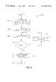
- FIG. 8is a flowchart of an operational sequence for using the cooling systems of FIGS. 1 A- 7 .
- One aspect of the inventionconcerns a cooling device, which may be implemented in a number of different forms as discussed below.
- This equipmentis used to cool the human body in aid of surgery, medical treatment, therapy, or comfort.
- the inventionutilizes evaporative and/or conductive cooling.
- Evaporative coolinginvolves applying a liquid to bodily regions and permitting evaporation to occur naturally or actively encouraging evaporation by directing an evaporating gas to the wetted bodily regions.
- conductive coolingthe cooling structure itself is cooled by some means such as evaporation. Since the cooling structure contacts the person, the person is ultimately cooled as well.
- Some exemplary cooling devicesinclude thermal pads, mattresses, and limb-conforming cooling sleeves.
- FIG. 1Ashows one example of thermal cooling pad 100 , in the form of a pillow.
- the pad 100comprises a material that readily absorbs water and is amenable to evaporative cooling when air flows as described below.
- this water absorbent materialmay comprise open cell foam, natural or synthetic sponge, “super-absorbent material,” etc.
- So-called “super-absorbent” materialsare substances capable of absorbing significantly more water than their own mass and volume, and one example is starch-grafted sodium polyacrylate (SAP), which is present in some types of diapers.
- SAP materialmay be processed into a fibrous, cotton-like form and woven into a sheet of gauze-like material.
- SAP materialcan absorb more than twice its volume and four-hundred times its mass in water. Thirty grams of SAP (less than the amount in a typical disposable diaper) can absorb approximately 1,000 grams of water. The evaporation of 1,000 grams of water removes 2,400 kilojoules of heat. If a typical seventy kilogram human has a specific heat near the specific heat of water, it would only take 1,470 kilojoules to reduce the mean body temperature by five degrees Celsius. Thus, as discovered by the present inventor(s), and illustrated by the foregoing example, water held by a super-absorbent layer can provide a significant amount of body cooling. The duration of cooling is significant, as well. Namely, while sleeping, the body metabolically generates about one hundred Watts of heat. This heat generation would be canceled by the evaporation of about 1,000 grams of water per hour, neglecting other thermal loads on the system. At this rate, one liter of water would provide about six hours of cooling.
- the pad 100defines an internal air flow passage 106 proceeding from an air inlet 110 to an air outlet 111 .
- the passage 106may assume a straight, serpentine, lattice, or other path shape designed to maximize the exposure of air in the passage to the foam structure, and thereby maximize evaporative cooling of the water-saturated foam.
- the pad 100may also define an internal liquid flow passage (not shown) for the purpose of admitting water or another evaporative cooling liquid into the pad.
- the liquid flow passagemay assume any desired shape, serpentine or other paths that thoroughly traverse the pad 100 are especially effective in saturating all areas of the pad 100 .
- multiple liquid flow passagesmay be used in parallel with each other to increase liquid flow or saturation effectiveness.
- the liquid flow passage(s)may include a water outlet, but this is unnecessary because the intent of the liquid flow passage is to saturate the pad 100 rather than transport liquid through the pad.
- the liquid flow passagemay comprise a void that is cut or otherwise defined from the foam material.
- the pad 100may include a perforated tube (not shown) that resides in the liquid flow passage, and distributes water through the perforations, in drip irrigation fashion.
- the liquid flow passage(s)may be omitted if the pad 100 is soaked in water prior to use, or manually irrigated with a cup, irrigation line, or faucet, etc.
- the pad 100may be capable of achieving sufficiently thorough water saturation through exclusively external, manual irrigation.
- the foam material of the pad 100preferably includes a sufficient density to support the intended body parts without collapsing the internal air flow passage(s). If desired, multiple layers of foam may be used, where softer foam is used for surfaces that contact the patient, and stiffer foam is used to maintain the internal passages.
- the pad 100includes a person-receiving upper surface 120 , and an opposite, bottom surface 121 .
- the bottom surface 121may be coated, adhered, or temporarily covered with a layer of sealant to prevent moisture from wetting bedding, pillows, or other materials beneath the pad 100 during use.
- the person-receiving surface 120may also be coated, adhered, or temporarily covered with a sealant to prevent the pad 100 from wetting the person.
- the foregoing sealant layersmay be permanently applied to the foam structure, for example, by chemical or heat curing. Alternatively, removable sealant may be used, such as a roll of plastic film or tailored cover that is removed after each use.
- any sealant placed on the person-receiving surface 120is preferably thermally conductive.
- the pad 100may also be cut, molded, or otherwise formed to defme shapes that help receive, prop, or position body parts. As illustrated, the pad 100 includes a recess 104 with adjoining ridges 102 to hold a person's head and neck in place.
- FIG. 1Bshows a different example 150 , which is shaped to accommodate a limb. This device 150 is cut, molded, or otherwise shaped to form an elongated channel 160 that defines a pair of parallel, outlying ridges 158 - 159 . Dimensions of the channel 160 may be selected to accommodate a desired shape and size of arm, forearm, leg, etc.
- the structure 150internally defines a “U-shaped” air flow passage 154 , with an inlet 152 and outlet 153 . Other air flow paths, (e.g. serpentine) are contemplated as well.
- FIG. 2shows one example embodied by the cooling mattress 200 .
- the mattress 200cools itself by receiving and then evaporating water or some other evaporative medium. Then, through conduction, the cooled mattress cools the person's body parts that thermally contact the mattress.
- the mattress 200comprises open cell foam or other material similar to the pad 100 , although the mattress 200 may be substantially larger so as to accommodate a reclining person.
- the mattressmay be cut, molded, or otherwise formed to define shapes that help receive, prop, or position body parts.
- the mattress 200includes a person-receiving upper surface 240 and an opposite, bottom surface 241 .
- the mattress 200includes at least one internal air flow passage 202 proceeding from an air inlet 208 to an air outlet 210 .
- the mattress 200also defines an internal liquid flow passage 204 to admit water or another volatile cooling liquid into the mattress 200 .
- the liquid flow passage 202may assume any desired shape, serpentine or other paths that thoroughly traverse the mattress 200 are especially effective in saturating all areas of the mattress 200 .
- the liquid flow passage 202may also include a perforated tube that resides in the passage and distributes water through the perforations, in drip irrigation fashion. Alternatively, the mattress 200 may be soaked in water prior to use, or manually irrigated with a cup, irrigation line, or faucet, etc. In the illustrated embodiment, the mattress 200 receives evaporative cooling liquid from a water source 206 .
- the mattress 200may be enhanced with various internal layers, as shown by the mattress sections depicted in FIGS. 3-4.
- the mattress section 300(FIG. 3) has a person-receiving surface 340 and an opposite, bottom surface 341 . Between the surfaces 340 - 341 lies a cushion layer 304 of absorbent material, such as open cell foam, natural or synthetic sponge, etc.
- the cushion layer 304provides the chief structure of the mattress, and thus establishes the desired level of firmness of the mattress 200 .
- the cushion layer 304internally defines an air manifold 302 , which is embodied by various interconnected air flow passages defined in the layer 304 .
- the layer 304lies an absorbent layer 305 , comprising a material with sufficient liquid absorbency for use as an evaporative cooling layer.
- the layer 305may have more softness than the layer 304 (to better cushion the person's body), and also have more absorbency than the layer 304 (to better retain water received from the liquid flow passages 303 ).
- the absorbent layer 305may comprise a super-absorbent material.
- the absorbent layer 305houses one or more liquid flow passages 303 to distribute water or another evaporative cooling liquid throughout the layer 305 .
- One or both of the surfaces 340 , 341may be coated, adhered, temporarily covered by, or otherwise topped with corresponding sealant layers 301 , 309 , such as plastic or another water impenetrable substance.
- the sealant layer 309prevents moisture in the mattress from wetting bedding, pillows, or other materials beneath the mattress 300 during use.
- the sealant layer 301prevents the mattress from wetting the person.
- any sealant placed on the person-receiving surface 340may comprise a thermally conductive material, or a material with sufficient thinness to avoid acting like a thermal insulator.
- a different mattress 400may be constructed as shown by FIG. 4 .
- the mattress 400includes a person-receiving surface 440 and an opposite, bottom surface 441 . Between these surfaces, the mattress 400 includes similar layers as in the mattress 300 , including a sealant layers 401 , absorbent layer 404 (with liquid flow passages 405 ), cushion layer 408 , and sealant layer 409 .
- the mattress 400includes an air manifold 406 that is separate from the cushion layer 408 , instead of being internally defined by voids in the layer 408 .
- the air manifold 406comprises a series of parallel tubes, open mesh, fibrous mat, layer of coil springs, or another suitably air permeable structure.
- a different embodiment of the inventionconcerns a selectively activated thermal cooling sleeve.
- This deviceis laid open to accept a person's limb, then closed to form a limb-supporting sleeve.
- this devicecomprises a block of open cell foam with a series of parallel, elongated channels removed, thereby defining a series of parallel ridges with trapezoidal or triangular cross-section.
- FIGS. 5-7show an exemplary cooling sleeve 500 in greater detail.
- the sleeve 500comprises a structure of open cell foam, synthetic or natural sponge, or other suitable water-absorbent material.
- the sleeve 500has a person-receiving surface 550 and an opposite, bottom surface 551 .
- the person-receiving surface 550may be temporarily or permanently covered or coated by a moisture barrier such as plastic or another sealant to prevent water leakage from the absorbent sleeve onto the person.
- the sleeve 500is cut, molded, or otherwise shaped to define multiple elongated channels 504 .
- Each channel 504defines a pair of outlying ridges or “blocks” 525 of the foam structure.
- the sleeve 500includes a series of parallel ridges 525 .
- the ridges 525have a trapezoidal lateral cross-section as best seen in FIG. 6 .
- the ridgesmay have triangular or other cross-sectional shapes that are narrower toward the person-receiving surface 550 and wider at the bottom surface 551 .
- the structure 500may comprise a single, unitary piece.
- a wrap layer 502constitutes a lower layer of foam integral to all ridges 525 .
- the ridges 525are physically distinct from each other, and a separate wrap layer 502 is added to provide a common mounting surface for all ridges.
- Each ridgehas an internal air flow passage 506 .
- the outermost ridgesinclude an inlet 508 and outlet 509 , which are connected to their respective internal air flow passages 506 .
- the ridges 525 and air flow passages 506are configured such that, when the outermost ridges are brought around to meet each other (FIG. 7 ), the ridges 525 form a contiguous sleeve having a body and a hollow, limb-receiving core 700 .
- the air flow passages 506cooperatively define a continuous conduit proceeding from ridge to ridge inside the sleeve body.
- FIG. 8depicts a sequence 800 for operating a thermal cooling pad, mattress, or selectively configurable limb sleeve.
- steps 800may be performed by various people, depending upon the environment where the cooling device is used.
- the steps 800may be performed by the subject or a family member at home, by attendants at a nursing facility, medical staff at a hospital, therapists at a treatment center, etc.
- FIG. 8is described primarily in the context of the cooling pad 100 of FIG. 1 A.
- the person and/or pad 100are positioned for operation of the pad 100 .
- the personshould be unclothed, or at least those body parts in contact with the pad.
- the pad 100is placed on the person's bed, and the person lies in bed with his/her head in the recess 104 .
- an operatorpositions the mattress 200 on a suitable surface and the person reclines atop the mattress 200 .
- the operatorpositions the person's treating limb upon one of the ridges 525 , and wraps the ridges around the limb to form a circle, such that adjacent ridges come together.
- the outermost ridgesmeet each other, and the all ridges collectively form the contiguous sleeve of FIG. 7 with the person's limb inside the core 700 .
- the padmay be moistened with water or another wetting agent that is suitably prone to evaporation, hypoallergenic, safe, effective in cooling, nonflammable, etc.
- An antibacterial agentmay be added to the wetting liquid if desired.
- wateris discussed as an exemplary wetting liquid.
- the cooling padmay be moistened, for example, by pouring water upon the pad 100 (FIG. 1) or sleeve 500 (FIGS. 5 - 6 ), activating a water source 206 (FIG. 2 ), or circulating water through liquid flow passages 303 , 405 internally provided in a cooling mattress 300 , 400 (FIG. 3, 4 ).
- the cooling padmay be pre-moistened by soaking the pad, running water over the pad, utilizing liquid flow passages, immersing the pad, etc. In this case, step 804 is performed before step 802 .
- the use of internal liquid flow passagesis most beneficial in larger foam structures, where manual wetting may not reach all areas of the foam structure.
- air flowbegins in step 806 .
- Input airmay be room air, filtered air, heated or cooled air, or dehumidified air, depending upon the cooling requirements of the specific application.
- Airflows into the inlet 110 , continues through the internal air flow passage(s), and ultimately exits from the outlet 111 .
- As air passes through the moist foam structureit encourages evaporation of water from the wetted foam, and therefore cools the foam structure. And because the foam structure thermally contacts the person's skin, the cooled structure cools the person's skin by conduction.
- the structuremay also employ evaporative cooling if water is permitted to seep from the foam structure onto the person's skin and subsequently evaporate.
- coolingmay be enhanced by permitting water to seep from the absorbent layer 305 into the cushion layer 304 .
- wetting of the cushion layer 304causes increased evaporative cooling by placing the flowing air (in the manifold 302 ) in proximity to a moist region of greater volume.
- step 808the operator decides whether to stop the procedure (step 808 ). If the cooling operation is not finished yet, cooling continues in step 810 . At this point, the operator may re-moisten the cooling field as needed to sustain evaporative cooling of the foam structure. Otherwise, when cooling is done, step 808 proceeds to step 812 , where the operator removes the pad 100 . Then, the routine ends in step 814 . At this point, the operator may dispose of the pad 100 . Alternatively, the sealant on the person-receiving surface may be removed and replaced with a new or sanitized cover for convenient reuse of the cooling structure.
Landscapes
- Health & Medical Sciences (AREA)
- Vascular Medicine (AREA)
- Thermal Sciences (AREA)
- Engineering & Computer Science (AREA)
- Biomedical Technology (AREA)
- Heart & Thoracic Surgery (AREA)
- Physics & Mathematics (AREA)
- Life Sciences & Earth Sciences (AREA)
- Animal Behavior & Ethology (AREA)
- General Health & Medical Sciences (AREA)
- Public Health (AREA)
- Veterinary Medicine (AREA)
- Mattresses And Other Support Structures For Chairs And Beds (AREA)
- Thermotherapy And Cooling Therapy Devices (AREA)
Abstract
Description
Claims (14)
Priority Applications (2)
| Application Number | Priority Date | Filing Date | Title |
|---|---|---|---|
| US09/460,478US6402775B1 (en) | 1999-12-14 | 1999-12-14 | High-efficiency cooling pads, mattresses, and sleeves |
| US10/036,044US6764502B2 (en) | 1999-12-14 | 2001-12-28 | High-efficiency cooling pads, mattresses, and sleeves |
Applications Claiming Priority (1)
| Application Number | Priority Date | Filing Date | Title |
|---|---|---|---|
| US09/460,478US6402775B1 (en) | 1999-12-14 | 1999-12-14 | High-efficiency cooling pads, mattresses, and sleeves |
Related Child Applications (1)
| Application Number | Title | Priority Date | Filing Date |
|---|---|---|---|
| US10/036,044ContinuationUS6764502B2 (en) | 1999-12-14 | 2001-12-28 | High-efficiency cooling pads, mattresses, and sleeves |
Publications (1)
| Publication Number | Publication Date |
|---|---|
| US6402775B1true US6402775B1 (en) | 2002-06-11 |
Family
ID=23828868
Family Applications (2)
| Application Number | Title | Priority Date | Filing Date |
|---|---|---|---|
| US09/460,478Expired - Fee RelatedUS6402775B1 (en) | 1999-12-14 | 1999-12-14 | High-efficiency cooling pads, mattresses, and sleeves |
| US10/036,044Expired - Fee RelatedUS6764502B2 (en) | 1999-12-14 | 2001-12-28 | High-efficiency cooling pads, mattresses, and sleeves |
Family Applications After (1)
| Application Number | Title | Priority Date | Filing Date |
|---|---|---|---|
| US10/036,044Expired - Fee RelatedUS6764502B2 (en) | 1999-12-14 | 2001-12-28 | High-efficiency cooling pads, mattresses, and sleeves |
Country Status (1)
| Country | Link |
|---|---|
| US (2) | US6402775B1 (en) |
Cited By (27)
| Publication number | Priority date | Publication date | Assignee | Title |
|---|---|---|---|---|
| US20040064169A1 (en)* | 2002-09-30 | 2004-04-01 | Briscoe Kathleen E. | User interface for medical device |
| US20040064171A1 (en)* | 2002-09-30 | 2004-04-01 | Briscoe Kathleen E. | Feedback system for rapid induction of mild hypothermia |
| US6763671B1 (en)* | 2003-02-06 | 2004-07-20 | Ut-Battelle, Llc | Personal, closed-cycle cooling and protective apparatus and thermal battery therefor |
| US6843800B1 (en) | 1998-01-23 | 2005-01-18 | Innercool Therapies, Inc. | Patient temperature regulation method and apparatus |
| US20050027173A1 (en)* | 2003-07-31 | 2005-02-03 | Briscoe Kathleen E. | Brain injury protocols |
| US20050101911A1 (en)* | 2002-12-23 | 2005-05-12 | Chester Steven M. | Coolant control for rapid induction of mild hypothermia |
| US6991645B2 (en) | 1998-01-23 | 2006-01-31 | Innercool Therapies, Inc. | Patient temperature regulation method and apparatus |
| US20060026743A1 (en)* | 2004-08-06 | 2006-02-09 | Brian Farnworth | Gas distribution garment |
| US7001378B2 (en) | 1998-03-31 | 2006-02-21 | Innercool Therapies, Inc. | Method and device for performing cooling or cryo-therapies, for, e.g., angioplasty with reduced restenosis or pulmonary vein cell necrosis to inhibit atrial fibrillation employing tissue protection |
| US20060161231A1 (en)* | 2005-01-17 | 2006-07-20 | Gaymar Industries, Inc. | Non-occlusion convective blanket |
| US20060174392A1 (en)* | 2004-08-06 | 2006-08-10 | Brian Farnworth | Gas distribution garment having a spacer element |
| US20070011813A1 (en)* | 2004-03-16 | 2007-01-18 | Rathle Mario M | Self-ventilating and self-cooling variable geometry pillow |
| US7179279B2 (en) | 2002-09-30 | 2007-02-20 | Medtronic Physio Control Corp. | Rapid induction of mild hypothermia |
| US20080188360A1 (en)* | 2007-02-06 | 2008-08-07 | Chu Yong S | Inflatable cushion bag for striking |
| US20100137704A1 (en)* | 2008-12-02 | 2010-06-03 | Surgivision, Inc. | Medical mats with electrical paths and methods for using the same |
| US20110041246A1 (en)* | 2009-08-20 | 2011-02-24 | Hong Kong Applied Science And Technology Research Institute Co., Ltd. | Systems and methods providing temperature regulated cushion structure |
| US20120266822A1 (en)* | 2009-11-05 | 2012-10-25 | Jason Stevens | Cushioning device for large animals |
| WO2012153269A2 (en) | 2011-05-09 | 2012-11-15 | Tel Hashomer Medical Research Infrastructure And Services Ltd. | Providing evidence whether an intravascular conduit is correctly positioned |
| WO2013156438A1 (en) | 2012-04-17 | 2013-10-24 | Climazleeper Holding Aps | A means of transport with battery driven cooling of a sleeping driver |
| WO2014008182A1 (en)* | 2012-07-05 | 2014-01-09 | Stryker Corporation | Pressure ulcer management pad |
| US9089462B1 (en) | 2012-07-05 | 2015-07-28 | Stryker Corporation | Pressure ulcer management pad |
| US9138064B2 (en) | 2013-01-18 | 2015-09-22 | Fxi, Inc. | Mattress with combination of pressure redistribution and internal air flow guides |
| US20160038101A1 (en)* | 2014-08-06 | 2016-02-11 | Thomas Benner | Patient couch support, patient couch and system for dissipating heat of the patient couch support |
| US9392875B2 (en)* | 2013-01-18 | 2016-07-19 | Fxi, Inc. | Body support system with combination of pressure redistribution and internal air flow guide(s) for withdrawing heat and moisture away from body reclining on support surface of body support system |
| US20170231814A1 (en)* | 2016-02-17 | 2017-08-17 | Pamela J. Collins | Comfort Cooling Pad |
| EP3560389A1 (en) | 2015-04-23 | 2019-10-30 | Tempur-Pedic Management, LLC | Mattress assembly and methods for active ventilation of a support cushion |
| US10561562B1 (en) | 2010-04-16 | 2020-02-18 | Mark Erb | Automated physical therapy system |
Families Citing this family (111)
| Publication number | Priority date | Publication date | Assignee | Title |
|---|---|---|---|---|
| US7507249B2 (en)* | 2002-11-08 | 2009-03-24 | Kci Licensing, Inc. | Patient cooling system |
| US7555792B2 (en)* | 1998-11-06 | 2009-07-07 | Kci Licensing, Inc. | Patient cooling enclosure |
| US7266965B2 (en)* | 2000-06-21 | 2007-09-11 | Blackstone Ralf W | Air cooling device |
| US6901769B2 (en) | 2001-06-21 | 2005-06-07 | Ralf Blackstone | Air cooling device |
| US6993930B2 (en) | 2000-06-21 | 2006-02-07 | Ralf Blackstone | Air cooling device |
| US6971249B1 (en) | 2001-06-21 | 2005-12-06 | Ralf Blackstone | Air cooling device |
| US20090044932A1 (en)* | 2001-06-21 | 2009-02-19 | Blackstone Ralf W | Air cooling device |
| US7266966B2 (en)* | 2003-02-27 | 2007-09-11 | Ralf Warren Blackstone | Air cooling device |
| EP1917935B1 (en)* | 2002-03-15 | 2011-01-12 | The General Hospital Corporation | Method for selective disruption of fatty tissue by controlled cooling |
| US8840608B2 (en) | 2002-03-15 | 2014-09-23 | The General Hospital Corporation | Methods and devices for selective disruption of fatty tissue by controlled cooling |
| US7547320B2 (en)* | 2002-07-11 | 2009-06-16 | Life Recovery System Hd, Llc | Apparatus for altering the body temperature of a patient |
| US6969399B2 (en)* | 2002-07-11 | 2005-11-29 | Life Recovery Systems Hd, Llc | Apparatus for altering the body temperature of a patient |
| US7666213B2 (en)* | 2002-07-11 | 2010-02-23 | Life Recovery Systems Hd, Llc | Apparatus for altering the body temperature of a patient |
| ATE450233T1 (en)* | 2003-09-24 | 2009-12-15 | Dynatherm Medical Inc | MEDICAL DEVICE FOR ADJUSTING THE CORE TEMPERATURE OF THE BODY |
| US8182521B2 (en) | 2003-09-24 | 2012-05-22 | Dynatherm Medical Inc. | Methods and apparatus for increasing blood circulation |
| US7896910B2 (en) | 2004-05-17 | 2011-03-01 | Coolsystems, Inc. | Modular apparatus for therapy of an animate body |
| US7377935B2 (en) | 2004-09-24 | 2008-05-27 | Life Recovery Systems Hd, Llc | Apparatus for altering the body temperature of a patient |
| US7587901B2 (en) | 2004-12-20 | 2009-09-15 | Amerigon Incorporated | Control system for thermal module in vehicle |
| TW200701881A (en)* | 2005-04-12 | 2007-01-16 | Hyperion Innovations Inc | Portable heated padding for pets |
| US20060289421A1 (en)* | 2005-04-12 | 2006-12-28 | Hyperion Innovations, Inc. | Portable heated seating |
| US7854754B2 (en) | 2006-02-22 | 2010-12-21 | Zeltiq Aesthetics, Inc. | Cooling device for removing heat from subcutaneous lipid-rich cells |
| KR101039758B1 (en) | 2006-04-28 | 2011-06-09 | 젤티크 애스세틱스, 인코포레이티드. | Cryoprotectants for use with therapeutic devices for improved cooling of subcutaneous lipid-rich cells |
| US20070270925A1 (en)* | 2006-05-17 | 2007-11-22 | Juniper Medical, Inc. | Method and apparatus for non-invasively removing heat from subcutaneous lipid-rich cells including a coolant having a phase transition temperature |
| US7771461B2 (en) | 2006-08-24 | 2010-08-10 | Life Recovery Systems Hd, Llc | Apparatus for altering the body temperature of a patient |
| US8192474B2 (en)* | 2006-09-26 | 2012-06-05 | Zeltiq Aesthetics, Inc. | Tissue treatment methods |
| US9132031B2 (en) | 2006-09-26 | 2015-09-15 | Zeltiq Aesthetics, Inc. | Cooling device having a plurality of controllable cooling elements to provide a predetermined cooling profile |
| US20080077201A1 (en) | 2006-09-26 | 2008-03-27 | Juniper Medical, Inc. | Cooling devices with flexible sensors |
| US20080087316A1 (en) | 2006-10-12 | 2008-04-17 | Masa Inaba | Thermoelectric device with internal sensor |
| EP2567637B1 (en) | 2006-10-13 | 2014-08-06 | Gentherm Incorporated | Air conditioning bed |
| US8603150B2 (en) | 2006-12-04 | 2013-12-10 | Carefusion 2200, Inc. | Methods and apparatus for adjusting blood circulation |
| US9308148B2 (en)* | 2006-12-04 | 2016-04-12 | Thermatx, Inc. | Methods and apparatus for adjusting blood circulation |
| US20080221493A1 (en)* | 2006-12-07 | 2008-09-11 | Life Recovery Systems Hd, Llc | Apparatus for altering the body temperature of a patient and administering decompression to the patients torso |
| WO2008070849A2 (en) | 2006-12-07 | 2008-06-12 | Life Recovery Systems Hd, Llc | Apparatus for altering the body temperature of a patient |
| US7837638B2 (en) | 2007-02-13 | 2010-11-23 | Coolsystems, Inc. | Flexible joint wrap |
| US20080287839A1 (en)* | 2007-05-18 | 2008-11-20 | Juniper Medical, Inc. | Method of enhanced removal of heat from subcutaneous lipid-rich cells and treatment apparatus having an actuator |
| US20090018624A1 (en)* | 2007-07-13 | 2009-01-15 | Juniper Medical, Inc. | Limiting use of disposable system patient protection devices |
| US20090018625A1 (en)* | 2007-07-13 | 2009-01-15 | Juniper Medical, Inc. | Managing system temperature to remove heat from lipid-rich regions |
| US20090018626A1 (en)* | 2007-07-13 | 2009-01-15 | Juniper Medical, Inc. | User interfaces for a system that removes heat from lipid-rich regions |
| US8523927B2 (en) | 2007-07-13 | 2013-09-03 | Zeltiq Aesthetics, Inc. | System for treating lipid-rich regions |
| US20090018627A1 (en)* | 2007-07-13 | 2009-01-15 | Juniper Medical, Inc. | Secure systems for removing heat from lipid-rich regions |
| WO2009026471A1 (en) | 2007-08-21 | 2009-02-26 | Zeltiq Aesthetics, Inc. | Monitoring the cooling of subcutaneous lipid-rich cells, such as the cooling of adipose tissue |
| WO2009036077A1 (en) | 2007-09-10 | 2009-03-19 | Amerigon, Inc. | Operational control schemes for ventilated seat or bed assemblies |
| US8181290B2 (en) | 2008-07-18 | 2012-05-22 | Amerigon Incorporated | Climate controlled bed assembly |
| US9125497B2 (en) | 2007-10-15 | 2015-09-08 | Gentherm Incorporated | Climate controlled bed assembly with intermediate layer |
| US10337761B2 (en) | 2007-12-21 | 2019-07-02 | Ralf W. Blackstone | Microenvironmental cooling system |
| US20090177184A1 (en)* | 2008-01-09 | 2009-07-09 | Christensen Scott A | Method and apparatus for improving venous access |
| CN114715003A (en) | 2008-02-01 | 2022-07-08 | 金瑟姆股份公司 | Condensation and humidity sensor for thermoelectric devices |
| WO2010036732A1 (en)* | 2008-09-25 | 2010-04-01 | Zeltiq Aesthetics, Inc. | Treatment planning systems and methods for body contouring applications |
| US8603073B2 (en) | 2008-12-17 | 2013-12-10 | Zeltiq Aesthetics, Inc. | Systems and methods with interrupt/resume capabilities for treating subcutaneous lipid-rich cells |
| CA2760610C (en) | 2009-04-30 | 2017-09-19 | Zeltiq Aesthetics, Inc. | Device, system and method of removing heat from subcutaneous lipid-rich cells |
| US8893329B2 (en) | 2009-05-06 | 2014-11-25 | Gentherm Incorporated | Control schemes and features for climate-controlled beds |
| US8332975B2 (en) | 2009-08-31 | 2012-12-18 | Gentherm Incorporated | Climate-controlled topper member for medical beds |
| EP3714848A1 (en) | 2009-10-22 | 2020-09-30 | Coolsystems, Inc. | Temperature and flow control methods in a thermal therapy device |
| US8771329B2 (en) | 2010-01-08 | 2014-07-08 | Carefusion 2200, Inc. | Methods and apparatus for enhancing vascular access in an appendage to enhance therapeutic and interventional procedures |
| CA2787374A1 (en) | 2010-01-25 | 2011-07-28 | Zeltiq Aesthetics, Inc. | Home-use applicators for non-invasively removing heat from subcutaneous lipid-rich cells via phase change coolants, and associated devices, systems and methods |
| EP2380534A1 (en)* | 2010-04-22 | 2011-10-26 | EMPA Eidgenössische Materialprüfungs- und Forschungsanstalt | Cooling device |
| EP2912974A3 (en) | 2010-05-28 | 2015-12-09 | Marlow Industries, Inc. | System for thermoelectric personal comfort controlled bedding |
| US8676338B2 (en) | 2010-07-20 | 2014-03-18 | Zeltiq Aesthetics, Inc. | Combined modality treatment systems, methods and apparatus for body contouring applications |
| US8969703B2 (en) | 2010-09-13 | 2015-03-03 | Tempronics, Inc. | Distributed thermoelectric string and insulating panel |
| US9615967B2 (en) | 2010-12-30 | 2017-04-11 | Coolsystems, Inc. | Reinforced therapeutic wrap and method |
| US10722395B2 (en) | 2011-01-25 | 2020-07-28 | Zeltiq Aesthetics, Inc. | Devices, application systems and methods with localized heat flux zones for removing heat from subcutaneous lipid-rich cells |
| US20130013033A1 (en)* | 2011-04-06 | 2013-01-10 | Coolsystems, Inc. | System for Providing Treatment to a Mammal and Method |
| GB2492311B (en)* | 2011-05-20 | 2015-01-28 | Dhayan Tomas Ishigaki | Periorbital edema reduction |
| US10463565B2 (en) | 2011-06-17 | 2019-11-05 | Coolsystems, Inc. | Adjustable patient therapy device |
| KR20140045408A (en) | 2011-07-06 | 2014-04-16 | 템프로닉스, 인크. | Integration of distributed thermoelectric heating and cooling |
| WO2013052823A1 (en) | 2011-10-07 | 2013-04-11 | Gentherm Incorporated | Thermoelectric device controls and methods |
| US9989267B2 (en) | 2012-02-10 | 2018-06-05 | Gentherm Incorporated | Moisture abatement in heating operation of climate controlled systems |
| US10047981B2 (en) | 2012-07-30 | 2018-08-14 | Marlow Industries, Inc. | System and method for thermoelectric personal comfort controlled bedding |
| US10051973B2 (en)* | 2012-07-31 | 2018-08-21 | Sealy Technology Llc | Air conditioned mattresses |
| US9638442B2 (en) | 2012-08-07 | 2017-05-02 | Tempronics, Inc. | Medical, topper, pet wireless, and automated manufacturing of distributed thermoelectric heating and cooling |
| US9676310B2 (en) | 2012-09-25 | 2017-06-13 | Faurecia Automotive Seating, Llc | Vehicle seat with thermal device |
| US20140094884A1 (en)* | 2012-10-01 | 2014-04-03 | Zaheer Zaidi | Warming system |
| US9844460B2 (en) | 2013-03-14 | 2017-12-19 | Zeltiq Aesthetics, Inc. | Treatment systems with fluid mixing systems and fluid-cooled applicators and methods of using the same |
| US9545523B2 (en) | 2013-03-14 | 2017-01-17 | Zeltiq Aesthetics, Inc. | Multi-modality treatment systems, methods and apparatus for altering subcutaneous lipid-rich tissue |
| US10456320B2 (en) | 2013-10-01 | 2019-10-29 | Coolsystems, Inc. | Hand and foot wraps |
| CN105848964B (en)* | 2013-11-04 | 2020-01-03 | 坦普罗尼克斯公司 | Design of thermoelectric strings, plates and envelopes for function and durability |
| US9662962B2 (en) | 2013-11-05 | 2017-05-30 | Gentherm Incorporated | Vehicle headliner assembly for zonal comfort |
| US20150216719A1 (en) | 2014-01-31 | 2015-08-06 | Zeltiq Aesthetics, Inc | Treatment systems and methods for treating cellulite and for providing other treatments |
| WO2015123585A1 (en) | 2014-02-14 | 2015-08-20 | Gentherm Incorporated | Conductive convective climate controlled seat |
| US10675176B1 (en) | 2014-03-19 | 2020-06-09 | Zeltiq Aesthetics, Inc. | Treatment systems, devices, and methods for cooling targeted tissue |
| USD777338S1 (en) | 2014-03-20 | 2017-01-24 | Zeltiq Aesthetics, Inc. | Cryotherapy applicator for cooling tissue |
| US10952891B1 (en) | 2014-05-13 | 2021-03-23 | Zeltiq Aesthetics, Inc. | Treatment systems with adjustable gap applicators and methods for cooling tissue |
| US20160038336A1 (en) | 2014-08-05 | 2016-02-11 | Tamara L. HILTON | Integrated multisectional heat exchanger |
| US10568759B2 (en) | 2014-08-19 | 2020-02-25 | Zeltiq Aesthetics, Inc. | Treatment systems, small volume applicators, and methods for treating submental tissue |
| US10935174B2 (en) | 2014-08-19 | 2021-03-02 | Zeltiq Aesthetics, Inc. | Stress relief couplings for cryotherapy apparatuses |
| US11857004B2 (en) | 2014-11-14 | 2024-01-02 | Gentherm Incorporated | Heating and cooling technologies |
| US11639816B2 (en) | 2014-11-14 | 2023-05-02 | Gentherm Incorporated | Heating and cooling technologies including temperature regulating pad wrap and technologies with liquid system |
| WO2016077843A1 (en) | 2014-11-14 | 2016-05-19 | Cauchy Charles J | Heating and cooling technologies |
| KR20170132218A (en) | 2015-03-28 | 2017-12-01 | 더 리전트 오브 더 유니버시티 오브 캘리포니아 | Thermostatic temperature control cooler for biomedical applications |
| US11154418B2 (en) | 2015-10-19 | 2021-10-26 | Zeltiq Aesthetics, Inc. | Vascular treatment systems, cooling devices, and methods for cooling vascular structures |
| WO2017106475A1 (en)* | 2015-12-16 | 2017-06-22 | Purdue Research Foundation | Systems and methods for cooling an animal |
| HK1259174A1 (en) | 2016-01-07 | 2019-11-29 | Zeltiq Aesthetics, Inc. | Temperature-dependent adhesion between applicator and skin during cooling of tissue |
| US10765552B2 (en) | 2016-02-18 | 2020-09-08 | Zeltiq Aesthetics, Inc. | Cooling cup applicators with contoured heads and liner assemblies |
| CN109475747A (en)* | 2016-03-28 | 2019-03-15 | 加利福尼亚大学董事会 | Heat Exchange Modules and Systems for Medical Applications |
| JP7101123B2 (en) | 2016-03-28 | 2022-07-14 | ハイポサーミア デバイシズ,インコーポレイテッド | Heat exchange modules, systems and methods |
| US10687632B1 (en) | 2016-04-03 | 2020-06-23 | Soothsoft Innovations Worldwide, Inc. | PCM containing liquid saturated foam device |
| US10859295B2 (en) | 2016-04-13 | 2020-12-08 | ZeoThermal Technologies, LLC | Cooling and heating platform |
| US10555831B2 (en) | 2016-05-10 | 2020-02-11 | Zeltiq Aesthetics, Inc. | Hydrogel substances and methods of cryotherapy |
| US11382790B2 (en) | 2016-05-10 | 2022-07-12 | Zeltiq Aesthetics, Inc. | Skin freezing systems for treating acne and skin conditions |
| US10682297B2 (en) | 2016-05-10 | 2020-06-16 | Zeltiq Aesthetics, Inc. | Liposomes, emulsions, and methods for cryotherapy |
| EP3518843B1 (en) | 2016-09-28 | 2024-06-26 | Hypothermia Devices, Inc. | Heat exchange module, system and method |
| US11076879B2 (en) | 2017-04-26 | 2021-08-03 | Zeltiq Aesthetics, Inc. | Shallow surface cryotherapy applicators and related technology |
| CN107183997A (en)* | 2017-06-20 | 2017-09-22 | 安徽新兴翼凌机电发展有限公司 | A kind of novel and multifunctional hot-water heating is heat insulating bed |
| US11737914B2 (en) | 2017-11-17 | 2023-08-29 | Stryker Corporation | Thermal treatment devices |
| US11223004B2 (en) | 2018-07-30 | 2022-01-11 | Gentherm Incorporated | Thermoelectric device having a polymeric coating |
| WO2020028472A1 (en) | 2018-07-31 | 2020-02-06 | Zeltiq Aesthetics, Inc. | Methods, devices, and systems for improving skin characteristics |
| CN113167510B (en) | 2018-11-30 | 2025-10-03 | 金瑟姆股份公司 | Thermoelectric regulation system and method |
| US11152557B2 (en) | 2019-02-20 | 2021-10-19 | Gentherm Incorporated | Thermoelectric module with integrated printed circuit board |
| CN110393327B (en)* | 2019-07-11 | 2024-04-02 | 南京工业大学 | A cooling and dehumidifying vest for high-temperature operations using phase change materials and radiation reflective films |
| CN215304446U (en)* | 2021-03-15 | 2021-12-28 | 江苏里高智能家居有限公司 | bed with temperature adjustment |
| US12403057B1 (en) | 2021-04-16 | 2025-09-02 | Turn Medical, LLC | Proning face pack |
Citations (7)
| Publication number | Priority date | Publication date | Assignee | Title |
|---|---|---|---|---|
| US3867939A (en)* | 1972-05-18 | 1975-02-25 | Moore Perk Corp | Disposable, sterile temperature control applicator pad for medical application |
| US4107509A (en)* | 1977-03-07 | 1978-08-15 | Northern Electric Company | Apparatus for treating body members with heat and moisture |
| US4768250A (en)* | 1985-07-30 | 1988-09-06 | Fuji Electric Co., Ltd. | Fluidized bead bed |
| US5964723A (en)* | 1992-06-19 | 1999-10-12 | Augustine Medical, Inc. | Normothermic tissue heating wound covering |
| US5986163A (en)* | 1992-06-19 | 1999-11-16 | Augustine Medical, Inc. | Normothermic heater wound covering |
| US5991948A (en)* | 1994-10-28 | 1999-11-30 | Stanley; Eric | Fluid saturated foam container |
| US6119474A (en)* | 1997-08-26 | 2000-09-19 | Augustine Medical, Inc. | Inflatable thermal blanket for convectively and evaporatively cooling a body |
Family Cites Families (7)
| Publication number | Priority date | Publication date | Assignee | Title |
|---|---|---|---|---|
| US3757366A (en)* | 1971-08-18 | 1973-09-11 | W Sacher | Cushion for preventing and alleviating bedsores |
| US4233700A (en)* | 1979-05-31 | 1980-11-18 | Spann Donald C | Ventilated body positioner |
| US4844072A (en)* | 1985-12-27 | 1989-07-04 | Seabrook Medical Systems, Inc. | Liquid-circulating thermal therapy system |
| US5609619A (en)* | 1990-02-13 | 1997-03-11 | Exergen Corporation | Method and apparatus for heating bodies |
| US5226188A (en)* | 1992-06-26 | 1993-07-13 | Liou Yaw Tyng | Ventilated foam cushion |
| US6085369A (en)* | 1994-08-30 | 2000-07-11 | Feher; Steve | Selectively cooled or heated cushion and apparatus therefor |
| US5626386A (en)* | 1996-07-16 | 1997-05-06 | Atoma International, Inc. | Air cooled/heated vehicle seat assembly |
- 1999
- 1999-12-14USUS09/460,478patent/US6402775B1/ennot_activeExpired - Fee Related
- 2001
- 2001-12-28USUS10/036,044patent/US6764502B2/ennot_activeExpired - Fee Related
Patent Citations (7)
| Publication number | Priority date | Publication date | Assignee | Title |
|---|---|---|---|---|
| US3867939A (en)* | 1972-05-18 | 1975-02-25 | Moore Perk Corp | Disposable, sterile temperature control applicator pad for medical application |
| US4107509A (en)* | 1977-03-07 | 1978-08-15 | Northern Electric Company | Apparatus for treating body members with heat and moisture |
| US4768250A (en)* | 1985-07-30 | 1988-09-06 | Fuji Electric Co., Ltd. | Fluidized bead bed |
| US5964723A (en)* | 1992-06-19 | 1999-10-12 | Augustine Medical, Inc. | Normothermic tissue heating wound covering |
| US5986163A (en)* | 1992-06-19 | 1999-11-16 | Augustine Medical, Inc. | Normothermic heater wound covering |
| US5991948A (en)* | 1994-10-28 | 1999-11-30 | Stanley; Eric | Fluid saturated foam container |
| US6119474A (en)* | 1997-08-26 | 2000-09-19 | Augustine Medical, Inc. | Inflatable thermal blanket for convectively and evaporatively cooling a body |
Cited By (37)
| Publication number | Priority date | Publication date | Assignee | Title |
|---|---|---|---|---|
| US6991645B2 (en) | 1998-01-23 | 2006-01-31 | Innercool Therapies, Inc. | Patient temperature regulation method and apparatus |
| US7101386B2 (en) | 1998-01-23 | 2006-09-05 | Innercool Therapies, Inc. | Patient temperature regulation method and apparatus |
| US6843800B1 (en) | 1998-01-23 | 2005-01-18 | Innercool Therapies, Inc. | Patient temperature regulation method and apparatus |
| US7311725B2 (en) | 1998-01-23 | 2007-12-25 | Innercool Therapies, Inc. | Patient temperature regulation method and apparatus |
| US7001378B2 (en) | 1998-03-31 | 2006-02-21 | Innercool Therapies, Inc. | Method and device for performing cooling or cryo-therapies, for, e.g., angioplasty with reduced restenosis or pulmonary vein cell necrosis to inhibit atrial fibrillation employing tissue protection |
| US7179279B2 (en) | 2002-09-30 | 2007-02-20 | Medtronic Physio Control Corp. | Rapid induction of mild hypothermia |
| US20040064171A1 (en)* | 2002-09-30 | 2004-04-01 | Briscoe Kathleen E. | Feedback system for rapid induction of mild hypothermia |
| US7087075B2 (en) | 2002-09-30 | 2006-08-08 | Medtronic Emergency Response Systems, Inc. | Feedback system for rapid induction of mild hypothermia |
| US20040064169A1 (en)* | 2002-09-30 | 2004-04-01 | Briscoe Kathleen E. | User interface for medical device |
| US20050101911A1 (en)* | 2002-12-23 | 2005-05-12 | Chester Steven M. | Coolant control for rapid induction of mild hypothermia |
| US7056282B2 (en) | 2002-12-23 | 2006-06-06 | Medtronic Emergency Response Systems, Inc. | Coolant control for rapid induction of mild hypothermia |
| US6763671B1 (en)* | 2003-02-06 | 2004-07-20 | Ut-Battelle, Llc | Personal, closed-cycle cooling and protective apparatus and thermal battery therefor |
| US20050027173A1 (en)* | 2003-07-31 | 2005-02-03 | Briscoe Kathleen E. | Brain injury protocols |
| US20070011813A1 (en)* | 2004-03-16 | 2007-01-18 | Rathle Mario M | Self-ventilating and self-cooling variable geometry pillow |
| US7716940B2 (en) | 2004-08-06 | 2010-05-18 | Gore Enterprise Holdings, Inc. | Gas distribution garment having a spacer element |
| US20060026743A1 (en)* | 2004-08-06 | 2006-02-09 | Brian Farnworth | Gas distribution garment |
| US20060174392A1 (en)* | 2004-08-06 | 2006-08-10 | Brian Farnworth | Gas distribution garment having a spacer element |
| US20060161231A1 (en)* | 2005-01-17 | 2006-07-20 | Gaymar Industries, Inc. | Non-occlusion convective blanket |
| US20080188360A1 (en)* | 2007-02-06 | 2008-08-07 | Chu Yong S | Inflatable cushion bag for striking |
| US7758476B2 (en)* | 2007-02-06 | 2010-07-20 | Fitness Botics | Inflatable cushion bag for striking |
| US20100137704A1 (en)* | 2008-12-02 | 2010-06-03 | Surgivision, Inc. | Medical mats with electrical paths and methods for using the same |
| US20110041246A1 (en)* | 2009-08-20 | 2011-02-24 | Hong Kong Applied Science And Technology Research Institute Co., Ltd. | Systems and methods providing temperature regulated cushion structure |
| US20120266822A1 (en)* | 2009-11-05 | 2012-10-25 | Jason Stevens | Cushioning device for large animals |
| US9049841B2 (en)* | 2009-11-05 | 2015-06-09 | Jason Stevens | Cushioning device for large animals |
| US10561562B1 (en) | 2010-04-16 | 2020-02-18 | Mark Erb | Automated physical therapy system |
| WO2012153269A2 (en) | 2011-05-09 | 2012-11-15 | Tel Hashomer Medical Research Infrastructure And Services Ltd. | Providing evidence whether an intravascular conduit is correctly positioned |
| WO2013156438A1 (en) | 2012-04-17 | 2013-10-24 | Climazleeper Holding Aps | A means of transport with battery driven cooling of a sleeping driver |
| WO2014008182A1 (en)* | 2012-07-05 | 2014-01-09 | Stryker Corporation | Pressure ulcer management pad |
| US9089462B1 (en) | 2012-07-05 | 2015-07-28 | Stryker Corporation | Pressure ulcer management pad |
| US9138064B2 (en) | 2013-01-18 | 2015-09-22 | Fxi, Inc. | Mattress with combination of pressure redistribution and internal air flow guides |
| US9392875B2 (en)* | 2013-01-18 | 2016-07-19 | Fxi, Inc. | Body support system with combination of pressure redistribution and internal air flow guide(s) for withdrawing heat and moisture away from body reclining on support surface of body support system |
| US10477975B2 (en) | 2013-01-18 | 2019-11-19 | Fxi, Inc. | Mattress with combination of pressure redistribution and internal air flow guides |
| US20160038101A1 (en)* | 2014-08-06 | 2016-02-11 | Thomas Benner | Patient couch support, patient couch and system for dissipating heat of the patient couch support |
| DE102014215544A1 (en)* | 2014-08-06 | 2016-02-11 | Siemens Aktiengesellschaft | Patient support, patient support and system for removing heat from the patient support |
| CN105361884A (en)* | 2014-08-06 | 2016-03-02 | 西门子公司 | Patient couch support, patient couch and system for dissipating heat of the patient couch support |
| EP3560389A1 (en) | 2015-04-23 | 2019-10-30 | Tempur-Pedic Management, LLC | Mattress assembly and methods for active ventilation of a support cushion |
| US20170231814A1 (en)* | 2016-02-17 | 2017-08-17 | Pamela J. Collins | Comfort Cooling Pad |
Also Published As
| Publication number | Publication date |
|---|---|
| US6764502B2 (en) | 2004-07-20 |
| US20020058975A1 (en) | 2002-05-16 |
Similar Documents
| Publication | Publication Date | Title |
|---|---|---|
| US6402775B1 (en) | High-efficiency cooling pads, mattresses, and sleeves | |
| US6354099B1 (en) | Cooling devices with high-efficiency cooling features | |
| CA2295584C (en) | An inflatable thermal blanket for convectively and evaporatively cooling a body | |
| US7727267B2 (en) | Self-powered steady-state skin-cooling support surfaces | |
| US7273490B2 (en) | Heat wick for skin cooling | |
| JP4191384B2 (en) | A heat transfer blanket and method for managing patient temperature. | |
| US6473920B2 (en) | System for warming lower extremities of supine persons | |
| US6772825B2 (en) | Heat exchange support surface | |
| US7959658B2 (en) | Heating system to alleviate hypothermia | |
| US5411494A (en) | Sponge bath machine and method for using | |
| US7520889B2 (en) | Thermal blanket for warming the limbs | |
| US20080015665A1 (en) | Heat wick for skin cooling | |
| WO1996013234A1 (en) | Sponge bath garment | |
| US20070283481A1 (en) | Thermal bathwear | |
| JP2008289654A (en) | Temperature-regulating mattress | |
| ES2365189T3 (en) | METHOD AND APPLIANCE TO RELIEF INFESTATION OF BED COMPONENT INSECTS. | |
| US6740110B2 (en) | Method and devices of inflammation control, and therapy | |
| CN111683570A (en) | Mattress | |
| WO2006001980A2 (en) | A non-powered heat wick for skin cooling | |
| MXPA00000401A (en) | An inflatable thermal blanket for convectively and evaporatively cooling a body | |
| JPS61149742A (en) | Cooling mat | |
| WO1996013299A1 (en) | Sponge bath machine | |
| EP0794750A1 (en) | Sponge bath garment |
Legal Events
| Date | Code | Title | Description |
|---|---|---|---|
| AS | Assignment | Owner name:AUGUSTINE MEDICAL, INC, MINNESOTA Free format text:ASSIGNMENT OF ASSIGNORS INTEREST;ASSIGNOR:BIEBERICH, MARK THOMAS;REEL/FRAME:010481/0486 Effective date:19991213 | |
| AS | Assignment | Owner name:ARIZANT HEALTHCARE INC., MINNESOTA Free format text:ASSIGNMENT OF ASSIGNORS INTEREST;ASSIGNOR:AUGUSTINE MEDICAL, INC.;REEL/FRAME:013804/0785 Effective date:20030217 | |
| AS | Assignment | Owner name:MERRILL LYNCH CAPITAL, A DIVISION OF MERRILL LYNCH Free format text:SECURITY INTEREST;ASSIGNOR:ARIZANT HEALTHCARE INC.;REEL/FRAME:015629/0084 Effective date:20040730 | |
| FPAY | Fee payment | Year of fee payment:4 | |
| AS | Assignment | Owner name:GENERAL ELECTRIC CAPITAL CORPORATION,AS ADMINISTRA Free format text:SECURITY AGREEMENT;ASSIGNOR:ARIZANT HEALTHCARE INC.;REEL/FRAME:022813/0114 Effective date:20090611 | |
| AS | Assignment | Owner name:ARIZANT HEALTHCARE INC., MINNESOTA Free format text:RELEASE BY SECURED PARTY;ASSIGNOR:GE BUSINESS FINANCIAL SERVICES INC. (F/K/A MERRILL LYNCH BUSINESS FINANCIAL SERVICES INC.), AS ADMINISTRATIVE AGENT;REEL/FRAME:022813/0325 Effective date:20090611 | |
| FPAY | Fee payment | Year of fee payment:8 | |
| AS | Assignment | Owner name:GENERAL ELECTRIC CAPITAL CORPORATION, MARYLAND Free format text:ASSIGNMENT OF ASSIGNORS INTEREST;ASSIGNOR:ARIZANT HEALTHCARE INC.;REEL/FRAME:025137/0066 Effective date:20101013 | |
| AS | Assignment | Owner name:ARIZANT HEALTHCARE INC., MINNESOTA Free format text:CORRECTIVE ASSIGNMENT TO CORRECT THE NATURE OF THE CONVEYANCE AS A RELEASE BY SECURED PARTY, AND THE IDENTITY OF THE ASSIGNOR AND ASSIGNEE PREVIOUSLY RECORDED ON REEL 025137 FRAME 0066. ASSIGNOR(S) HEREBY CONFIRMS THE RELEASE OF SECURITY INTEREST IN ALL OF GRANTOR'S RIGHT, TITLE AND INTEREST IN PATENT RIGHTS;ASSIGNOR:GENERAL ELECTRIC CAPITAL CORPORATION, AS ADMINISTRATIVE AGENT;REEL/FRAME:025444/0901 Effective date:20101013 | |
| REMI | Maintenance fee reminder mailed | ||
| LAPS | Lapse for failure to pay maintenance fees | ||
| STCH | Information on status: patent discontinuation | Free format text:PATENT EXPIRED DUE TO NONPAYMENT OF MAINTENANCE FEES UNDER 37 CFR 1.362 | |
| FP | Lapsed due to failure to pay maintenance fee | Effective date:20140611 |