US6402764B1 - Everter and threadthrough system for attaching graft vessel to anastomosis device - Google Patents
Everter and threadthrough system for attaching graft vessel to anastomosis deviceDownload PDFInfo
- Publication number
- US6402764B1 US6402764B1US09/440,116US44011699AUS6402764B1US 6402764 B1US6402764 B1US 6402764B1US 44011699 AUS44011699 AUS 44011699AUS 6402764 B1US6402764 B1US 6402764B1
- Authority
- US
- United States
- Prior art keywords
- graft vessel
- tool
- everter
- anastomosis device
- graft
- Prior art date
- Legal status (The legal status is an assumption and is not a legal conclusion. Google has not performed a legal analysis and makes no representation as to the accuracy of the status listed.)
- Expired - Lifetime
Links
Images


Classifications
- A—HUMAN NECESSITIES
- A61—MEDICAL OR VETERINARY SCIENCE; HYGIENE
- A61F—FILTERS IMPLANTABLE INTO BLOOD VESSELS; PROSTHESES; DEVICES PROVIDING PATENCY TO, OR PREVENTING COLLAPSING OF, TUBULAR STRUCTURES OF THE BODY, e.g. STENTS; ORTHOPAEDIC, NURSING OR CONTRACEPTIVE DEVICES; FOMENTATION; TREATMENT OR PROTECTION OF EYES OR EARS; BANDAGES, DRESSINGS OR ABSORBENT PADS; FIRST-AID KITS
- A61F2/00—Filters implantable into blood vessels; Prostheses, i.e. artificial substitutes or replacements for parts of the body; Appliances for connecting them with the body; Devices providing patency to, or preventing collapsing of, tubular structures of the body, e.g. stents
- A61F2/02—Prostheses implantable into the body
- A61F2/04—Hollow or tubular parts of organs, e.g. bladders, tracheae, bronchi or bile ducts
- A61F2/06—Blood vessels
- A61F2/064—Blood vessels with special features to facilitate anastomotic coupling
- A—HUMAN NECESSITIES
- A61—MEDICAL OR VETERINARY SCIENCE; HYGIENE
- A61B—DIAGNOSIS; SURGERY; IDENTIFICATION
- A61B17/00—Surgical instruments, devices or methods
- A61B17/064—Surgical staples, i.e. penetrating the tissue
- A61B17/0644—Surgical staples, i.e. penetrating the tissue penetrating the tissue, deformable to closed position
- A—HUMAN NECESSITIES
- A61—MEDICAL OR VETERINARY SCIENCE; HYGIENE
- A61B—DIAGNOSIS; SURGERY; IDENTIFICATION
- A61B17/00—Surgical instruments, devices or methods
- A61B17/11—Surgical instruments, devices or methods for performing anastomosis; Buttons for anastomosis
- A—HUMAN NECESSITIES
- A61—MEDICAL OR VETERINARY SCIENCE; HYGIENE
- A61B—DIAGNOSIS; SURGERY; IDENTIFICATION
- A61B17/00—Surgical instruments, devices or methods
- A61B17/064—Surgical staples, i.e. penetrating the tissue
- A61B2017/0641—Surgical staples, i.e. penetrating the tissue having at least three legs as part of one single body
- A—HUMAN NECESSITIES
- A61—MEDICAL OR VETERINARY SCIENCE; HYGIENE
- A61B—DIAGNOSIS; SURGERY; IDENTIFICATION
- A61B17/00—Surgical instruments, devices or methods
- A61B17/11—Surgical instruments, devices or methods for performing anastomosis; Buttons for anastomosis
- A61B2017/1107—Surgical instruments, devices or methods for performing anastomosis; Buttons for anastomosis for blood vessels
Definitions
- the inventionrelates to an everter and threadthrough device for attaching a graft vessel to an anastomosis device which can be used for forming a sutureless connection between a bypass graft and a blood vessel.
- Vascular anastomosisis a procedure by which two blood vessels within a patient are surgically joined together. Vascular anastomosis is performed during treatment of a variety of conditions including coronary artery disease, diseases of the great and peripheral vessels, organ transplantation, and trauma.
- coronary artery diseaseCAD
- an occlusion or stenosis in a coronary arteryinterferes with blood flow to the heart muscle.
- Treatment of CADinvolves the grafting of a vessel in the form of a prosthesis or harvested artery or vein to reroute blood flow around the occlusion and restore adequate blood flow to the heart muscle. This treatment is known as coronary artery bypass grafting (CABG).
- CABGcoronary artery bypass grafting
- thrombi and atherosclerotic lesionsare formed at and around the grafted artery, which can result in the reoccurrence of ischemia.
- the thrombi and atherosclerotic lesionsmay be caused by the configuration of the sutured anastomosis site. For example, an abrupt edge at the anastomosis site may cause more stenosis than a more gradual transition.
- sutureless vascular anastomosis devicewhich easily connects a graft to a target vessel. It would also be desirable to provide a sutureless anastomosis device which is formed of one piece and is secured to the target vessel in a single step.
- the inventionprovides an everter tool useful for everting an end of a graft vessel over an end of an anastomosis device.
- the everter toolpreferably includes a mechanism which expands an end of a graft vessel and everts the end of the graft vessel over an anastomosis device mounted on a deployment tool.
- the mechanismcan include a first member having fingers at a distal end thereof, the fingers being expandable from a first configuration which fits within the and of the graft vessel to a second configuration which expands the end of the graft vessel, and an optional second member cooperating with the first member such that the second member is movable from a first location at which the fingers are in the first configuration to a second location at which the second member expands the fingers to the second configuration.
- the everter toolcan include various features.
- the everter toolcan be slidably received in a bore of an everter fixture and a handle on the everter tool can be used to engage a first portion of the handle with the first member and a second portion of the handle with the second member, the handle being movable in an axial direction such that the second portion pushes the second member along the first member until a distal end of the second member expands the fingers from the first configuration to the second configuration after which the first portion pushes the first member along the bore until the fingers evert the graft vessel.
- a deployment toolhaving an anastomosis device mounted on a distal end thereof and a graft vessel fitted through the anastomosis device can be located in the bore of the housing such that the fingers can be pushed into a portion of the graft vessel extending beyond an end of the anastomosis device.
- a threadthrough devicecan be used for pulling the graft vessel through the anastomosis device.
- the threadthrough devicecan include a clamp which attaches to an end of the graft vessel and an extension attached to the clamp, the threadthrough device being sized to pass through the anastomosis device.
- the threadthrough devicecan also include a tongue pivotally connected to the clamp, the clamp being movable towards and away from the tongue such that the graft vessel can be clamped between the clamp and the tongue.
- the threadthrough deviceincludes three clamps and the extension comprises a wire connected to each of the clamps.
- the anastomosis deviceincludes barbs for penetrating the graft vessel and the everter tool includes a membrane engageable with the anastomosis device such that the barbs penetrate the graft vessel when the membrane is pressed against the anastomosis device.
- the inventionalso provides a method of everting a graft vessel onto an anastomosis device, the method comprising locating a graft vessel in an anastomosis device mounted on a deployment tool such that a first portion of the graft vessel is within the deployment tool and a second portion of the graft vessel extends from an end of the deployment tool, expanding the second portion of the graft vessel, and everting the second portion of the graft vessel over the anastomosis device.
- the methodcan be carried out in any suitable manner.
- the step of locating the graft vessel in the anastomosis devicecan be carried out by attaching an end of the graft vessel to a threadthrough device and passing the threadthrough device through the deployment tool.
- the step of expanding the second portion of the graft vesselcan be carried out by inserting an everter tool into the second portion of the graft vessel.
- the everter toolcan optionally be pressed against the distal end of the deployment tool until barbs on a distal end of the anastomosis device penetrate the graft vessel.
- the step of expanding the second portion of the graft vesselcan be carried out by inserting fingers of the everter tool into the second portion of the graft vessel and expanding the fingers within the second portion of the graft vessel.
- the step of everting the second portion of the graft vesselcan be carried out by pressing the everter tool against the deployment tool.
- the step of expanding the second portion of the graft vesselcan be carried out by locating the deployment tool in a bore of an everter fixture and sliding the everter tool from a first position to a second position along the bore.
- the step of everting the second portion of the graft vesselcan be carried out by sliding the everter from the second position to a third position along the bore.
- the step of locating he graft vessel in the anastomosis devicecan be carried out by passing a threadthrough device through the deployment tool, the threadthrough device having a clamp attached to an end of the graft vessel and a wire extending from the clamp, the wire being pulled through an angled hole in the fixture while the graft vessel is pulled through the anastomosis device.
- the clampcan be designed to spring open after passing out of the anastomosis device leaving a segment of the graft vessel extending beyond a distal end of the anastomosis device.
- the step of everting the graft vesselcan be carried out by pressing a first portion of the everter tool against an annular section of the graft vessel and moving a second portion of the everter tool in contact with an inner surface of the graft vessel until the inner surface is turned inside out over the anastomosis device.
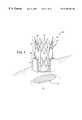
- FIG. 1is a perspective view of a first embodiment of an anastomosis device in a configuration prior to use with a graft vessel everted over the device;
- FIG. 2is a perspective view of the anastomosis device of FIG. 1 in a deployed configuration
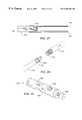
- FIG. 3is a perspective view of an anastomosis device deployment system
- FIG. 4is an enlarged perspective view of the distal end of the anastomosis device deployment system of FIG. 3 with an anastomosis device prior to deployment;
- FIG. 5is a side cross sectional view of the anastomosis device deployment system puncturing the target vessel to advance the anastomosis device into the target vessel wall;
- FIG. 6is a side cross sectional view of the anastomosis device deployment system advancing the anastomosis device into the target vessel wall;
- FIG. 7is a side cross sectional view of the anastomosis device deployment system with an expanded first annular flange
- FIG. 8is a side cross sectional view of the anastomosis device deployment system expanding a second annular flange
- FIG. 9is a schematic side cross-sectional view of a deployment tool taken along line A—A of FIG. 3, the deployment tool is shown during a vessel puncturing step;
- FIG. 10is a schematic side cross-sectional view of the deployment tool of FIG. 9 shown during an anastomosis device insertion step;
- FIG. 11is a schematic side cross-sectional view of the deployment tool of FIG. 9 shown during an anastomosis device expansion step;
- FIG. 12is a schematic side cross-sectional view of the deployment tool of FIG. 9 shown after the anastomosis device has been fully deployed;
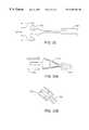
- FIG. 13shows details of a threadthrough device which can be used in a preferred technique for everting a graft vessel over an anastomosis device in accordance with the invention
- FIG. 14shows how the threadthrough device of FIG. 13 can be passed through a deployment tool mounted in an everter fixture
- FIG. 15shows how an end of a graft vessel can be prepared to be clamped by the threadthrough device
- FIG. 16shows how the threadthrough device can be passed through a funnel at the back end of a deployment tool
- FIG. 17shows how tapered grooves in the funnel align and close the jaws of the threadthrough device
- FIG. 18shows how the jaws can be manipulated to introduce the lumen of the graft vessel to fingers of an everter tool after passing through the anastomosis device
- FIG. 19shows how fingers of an everter tool can be inserted in the end of the graft vessel
- FIG. 20shows details of the everter tool shown in FIG. 19
- FIG. 21shows details of an everter fixture
- FIG. 22shows details of how the graft vessel is expanded
- FIG. 23shows details of the everter tool shown in FIG. 22
- FIG. 24shows details of how barbs on the anastomosis device penetrate through the graft vessel
- FIG. 25shows details of the graft vessel is everted over the anastomosis device
- FIG. 26shows the results of the eversion process
- FIG. 27shows details of the everter arrangement shown in FIG. 26
- FIG. 28shows the everter tool after separation from the deployment tool having the graft vessel everted over the anastomosis device
- FIG. 29shows details of the everter fixture
- FIGS. 30 and 31show details of the fixture shown in FIG. 29;
- FIG. 32shows an alternative technique for everting the graft vessel over the anastomosis device
- FIGS. 33A and 33Bshow another alternative technique for everting the graft vessel over the anastomosis device
- FIGS. 34A and 34Bshow a further alternative technique for everting the graft vessel over the anastomosis device
- FIG. 35shows a still further alternative technique for everting the graft vessel over the anastomosis device
- FIG. 36shows yet another alternative technique for everting the graft vessel over the anastomosis device
- FIGS. 37A and 37Bshow an additional alternative technique for everting the graft vessel over the anastomosis device
- FIGS. 38A and 38Bshow another alternative technique for everting the graft vessel over the anastomosis device
- FIGS. 39A and 39Bshow a further alternative technique for everting the graft vessel over the anastomosis device
- FIG. 40shows an alternative technique for everting the graft vessel over the anastomosis device
- FIGS. 41A-Eshow another alternative technique for everting the graft vessel over the anastomosis device.
- FIG. 42shows another eversion technique.
- target vesselis thus used to refer to vessels within the patient which are connected to either or both of the upstream and downstream end of the graft vessel.
- a large vessel anastomotic deviceis used with large diameter target vessels such as the aorta or its major side branches or a small vessel anastomotic device is used for a target vessel which has a small diameter such as a coronary artery.
- the deviceIn deploying a large vessel anastomotic device, the device (with one end of a graft vessel attached thereto) is inserted into an incision in a wall of the target vessel with a deformable section in a first configuration, and the deformable section is radially expanded to a second configuration to deploy a flange.
- the flangeapplies an axial force against the wall of the target vessel.
- the flangecan be configured to apply a radial force, substantially transverse to the device longitudinal axis, against the wall of the target vessel, to secure the device to the target vessel.
- the devicecan have a plurality of deformable sections forming distal and proximal flanges. With the proximal and distal end flanges deployed, the device can be prevented from shifting proximally out of the target vessel or distally further into the interior of the target vessel.
- the large vessel devicescan be configured to connect to target vessels of various sizes having a wall thickness of at least about 0.5 mm, and typically about 0.5 mm to about 5 mm.
- the large vessel anastomotic deviceis configured to longitudinally collapse as the deformable section is radially expanded.
- the surgeoncan control the longitudinal collapse to thereby position the distal end flange at a desired location at least partially within the incision in the target vessel wall.
- the surgeoncan also control the position of the proximal end flange by longitudinally collapsing the device to a greater or lesser degree, to thereby position the proximal end flange at a desired location in contact with the target vessel.
- the devicecan be longitudinally collapsed to position the flanges against the target vessel wall and effectively connect the device thereto.
- This featureis significant because the device must be connected to target vessels which have a wide range of wall thickness.
- the aortic wall thicknessis typically about 1.4 mm to about 4.0 mm and the aorta diameter can range from about 25 to about 65 mm in diameter. Therefore, regardless of the thickness of the target vessel wall, the degree of deployment of the proximal end flange, and thus the longitudinal collapse of the device, can be controlled by the physician to thereby effectively connect the device to the target vessel.
- surgeonmay choose between partially deploying the proximal end flange so that it is positioned against an outer surface of the target vessel wall, or fully deploying the flange to position it in contact with the media of the target vessel wall within the incision in the target vessel wall.
- the devicecan be used on small target vessels having a wall thickness of less than about 1.0 mm, and typically about 0.1 mm to about 1 mm in the case of coronary arteries.
- the small vessel devicesprovide sutureless connection without significantly occluding the small inner lumen of the target vessel or impeding the blood flow therethrough.
- the small vessel devicescan include an outer flange (with the graft vessel connected thereto) loosely connected to an inner flange before insertion into the patient with the space between the loosely connected inner and outer flanges being at least as great as the wall thickness of the target vessel so that the inner flange can be inserted through an incision in the target vessel and into the target vessel lumen, with the outer flange outside the target vessel.
- the outer and inner flangesWith the outer and inner flanges in place on either side of a wall of the target vessel, tightening the flanges together compresses a surface of the graft vessel against the outer surface of the target vessel.
- This configurationforms a continuous channel between the graft vessel and the target vessel, without the need to suture the graft vessel to the target vessel wall and preferably without the use of hooks or barbs which puncture the target vessel.
- a large vessel devicecan be used to connect the proximal end of the graft vessel to the aorta
- a small vessel devicecan be used to connect the distal end of the graft vessel to an occluded coronary artery.
- the surgeonmay wish to avoid this region and connect the proximal end of the graft vessel to any other adjacent less diseased vessel, such as the arteries leading to the arms or head.
- the devicescan be used with venous grafts, such as a harvested saphenous vein graft, arterial grafts, such as a dissected mammary artery, or a synthetic prosthesis, as required.
- connection of the large vessel devicedoes not require the stoppage of blood flow in the target vessel.
- the anastomotic devicescan be connected to the target vessel without the use of cardiopulmonary bypass.
- anastomosis techniqueswherein the aorta is clamped to interrupt blood flow to the area of the aortic wall to which a vein is to be anastomosed may result in liberation of plaques and tissue fragments which can lead to organ dysfunction, such as strokes, renal failure, or intestinal ischemia.
- severely diseased aortasmay not provide an area suitable for clamping due to significant calcification of the aortic wall.
- the surgeondoes not need significant room inside the patient to connect the anastomotic devices to the target vessel.
- the anastomotic devicesallow the proximal end of the graft vessel to be connected to any part of the aorta. All parts of the aorta are accessible to the large vessel anastomosis devices, even when minimally invasive procedures are used. Consequently, the graft vessel may be connected to the descending aorta, so that the graft vessel would not be threatened by damage during a conventional sternotomy if a second operation is required at a later time.
- a sutureless connectioncan be provided between a graft and a target vessel, while minimizing thrombosis or restenosis associated with the anastomosis.
- the anastomotic devicescan be attached to the target vessel inside a patient remotely from outside the patient using specially designed applicators, so that the devices are particularly suitable for use in minimally invasive surgical procedures where access to the anastomosis site is limited.
- the devicesallow the anastomosis to be performed very rapidly, with high reproducibility and reliability, without clamping, and with or without the use of cardiopulmonary bypass.
- the surgeonoperates a deployment tool using both hands.
- One handsupports the tool via a handle while the other twists an actuation knob to deploy the anastomotic device.
- Locating the actuation knob on the tool's main axisminimizes the tendency of reaction forces to wobble the tool keeping it stable and in proper position during deployment.
- the twisting motionis converted to linear displacements by a set of rotating cams that engage a trocar, holder, and expander. The cams control the sequence of relative motions between the instrument's trocar and device deployment mechanisms.
- a surgeonwill place the tip of the instrument (the mechanical stop) in light contact with the site on the aorta to be anastomosed. Having located a suitable site, the surgeon then twists the actuation knob to fire the spring-loaded trocar and continues twisting to deploy the anastomotic device.
- the trocarpenetrates the aortic wall at a high rate of speed to minimize any unintended deformation of the aorta and maintains a substantially fluid-tight seal at the puncture site.
- the trocardilates as the anastomotic device and its holder tube (crown) are advanced through it, thus retracting the aortic tissue and serving as an introducer for the device.
- the trocaris withdrawn.
- the anastomotic deviceis then expanded to its full diameter and an inner flange is deployed.
- the deviceis then drawn outwards towards the instrument (mechanical stop) to seat the inner flange firmly against the intimal wall of the aorta.
- An outer flangeis then deployed from the external side, compressing the aortic wall between the inner and outer flanges and the device is disengaged from the instrument completing the anastomosis.
- FIG. 1illustrates the distal portion of an anastomosis device 10 according to a first embodiment of the present invention, the proximal portion (not shown) being adapted to be deployed by a deployment tool which will be explained later.
- the anastomosis device 10includes a plurality of axial members 12 and a plurality of struts 14 interconnecting the axial members.
- the axial members 12 and struts 14form a first linkage 16 at a first end of the device and a second linkage 18 at a second end of the device.
- the first and second linkages 16 , 18form inner and outer flanges 20 , 22 when the anastomosis device 10 is deployed as illustrated in FIG. 2 .
- the deployed flanges 20 , 22may be annular ring shaped or conical in shape.
- the first and second linkages 16 , 18are connected by a central connecting portion 24 .
- a graft vessel 30is inserted through a center of the tubular anastomosis device 10 and is everted over the first linkage 16 at the first end of the device.
- the first end of the devicemay puncture part way or all the way through the graft vessel wall to hold the graft vessel 30 on the device.
- An opening 34is formed in the target vessel 32 to receive the graft vessel 30 and anastomosis device 10 .
- the inner and outer flanges 20 , 22are formed as shown in FIG. 2 to secure the graft vessel to the target vessel by trapping the wall of the target vessel between the two flanges.
- the anastomosis device 10forms a smooth transition between the target vessel 32 and the graft vessel 30 which helps to prevent thrombi formation.
- the inner and outer flanges 20 , 22are formed by radial expansion of the anastomosis device 10 as follows.
- the first and second linkages 16 , 18are each made up of a plurality of axial members 12 and struts 14 .
- the struts 14are arranged in a plurality of diamond shapes with adjacent diamond shapes connected to each other to form a continuous ring of diamond shapes around the device.
- One axial member 12extends through a center of each of the diamond shapes formed by the struts 14 .
- a reduced thickness section 26 or hinge in each of the axial members 12provides a location for concentration of bending of the axial members.
- each of the diamond shaped linkages of struts 14are elongated in a circumferential direction causing a top and bottom of each of the diamond shapes to move closer together.
- the axial members 12bend along the reduced thickness sections 26 folding the ends of the device outward to form the inner and outer flanges 20 , 22 with the result that the wall of the target vessel 32 is trapped between the flanges and the everted graft vessel 30 is secured to the target vessel.
- the struts 14may be straight or curved members having constant or varying thicknesses.
- the axial members 12may have the reduced thickness sections 26 positioned at a center of each of the diamond shapes or off center inside the diamond shapes. The positioning and size of the reduced thickness sections 26 will determine the location of the flanges 20 , 22 and an angle the flanges make with an axis of the device when fully deployed.
- a final angle between the flanges 20 , 22 and longitudinal axis of the device 10is about 40-140 degrees, preferably about 50-90 degrees.
- FIGS. 3-7illustrate a deployment system 150 and sequence of deploying an anastomosis device 120 such as the device shown in FIGS. 1-2 with the deployment system.
- the deployment system 150includes a hollow outer trocar 152 (not shown in FIG. 3 ), a holder tube 154 positioned inside the trocar, and an expander tube 156 slidable inside the holder tube.
- the anastomosis device 120is attached to a distal end of the holder tube 154 by inserting T-shaped ends 112 of pull tabs 110 in slots 158 around the circumference of the holder tube.
- the trocar 152 , holder tube 154 , and expander tube 156are all slidable with respect to one another during operation of the device.
- a device handle 160is provided for moving the tubes with respect to one another will be described in further detail below with respect to FIGS. 8-11.
- the holder tube 154 , expander tube 156 , and the anastomosis device 120are positioned within the trocar 152 for insertion.
- the trocar 152has a hollow generally conical tip with a plurality of axial slots 162 which allow the conical tip to be spread apart so that the anastomosis device 120 can slide through the opened trocar.
- the trocar 152acting as a tissue retractor and guide, is inserted through the wall of the target vessel 32 forming an opening 34 .
- the anastomosis device 120is then advanced into or through the target vessel wall 32 with the holder tube 154 .
- the advancing of the holder tube 154causes the distal end of the trocar 152 to be forced to spread apart.
- the inner annular flange 20is deployed by advancing the expander tube 156 into the anastomosis device.
- the advancing of the expander tube 156increases the diameter of the anastomosis device 120 causing the inner flange to fold outward from the device. This expanding of the inner flange may be performed inside the vessel and then the device 120 may be drawn back until the inner flange abuts an interior of the target vessel wall 32 .
- the holder tube 154is advanced forming the outer flange.
- the anastomosis device 120drops into a radial groove 157 on an exterior of the expander tube 156 which holds the anastomosis device stationary on the expander tube 156 .
- the holder tube 154is then moved forward to detach the entire anastomosis device by disengaging the pull tabs 130 from the slots 158 in the holder tube and causing the outer flange to be deployed.
- shoulders 134 on the deviceshown most clearly in FIGS.
- One alternative embodiment of the holder tube 154employs a plurality of flexible fingers which receive the pull tabs 130 of the anastomosis device 120 .
- each pull tab 130is received by an independent finger of the holder tube 154 .
- the flexible fingersflex outward bending the pull tabs 130 outward.
- FIGS. 9-12illustrate the operation of the handle 160 to move the trocar 152 , the holder tube 154 , and the expander tube 156 with respect to one another to deploy the anastomosis device 120 according to the present invention.
- the handle 160includes a grip 170 and a trigger 172 pivotally mounted to the grip at a pivot 174 .
- the trigger 172includes a finger loop 176 and three contoured cam slots 178 , 180 , 182 corresponding to the trocar 152 , holder tube 154 , and expander tube 156 , respectively.
- Each of these tubeshas a fitting 184 at a distal end thereof.
- a pin 186 connected to each of the fittings 184slides in a corresponding one of the cam slots 178 , 180 , 182 .
- a fourth cam slot and tubemay be added to control deployment of the outer flange.
- the handlecan be modified to include fewer cam slots for deployment of the inner and outer flanges.
- the handle 160is shown in FIG. 8 in an insertion position in which the trocar 152 extends beyond the holder tube 154 and the expander tube 156 for puncturing of the target vessel wall 32 .
- a flexible sealsuch as heat shrinkable plastic tubing or a molded elastomer tubing can be provided on the outer surface of the trocar 152 such that the seal covers the axial slots 162 at a location spaced from the tip of the trocar to minimize leaking of blood form the target vessel after the incision is formed.
- the trocaris actuated by a mechanism which causes the trocar to penetrate the aorta wall it a high rate of speed to minimize deformation of the aorta and maintain a fluid tight seal at the puncture site in a manner similar to biopsy gun.
- the spring mechanism attached to the trocar and/or the handlecan be used to fire the trocar at the incision site. Any suitable actuating mechanism can be used to fire the trocar in accordance with the invention.
- the trigger 172is rotated from the position illustrated in FIG. 9 to the successive positions illustrated in FIGS. 10-12, the pins 186 slide in the cam slots 178 , 180 , 182 to move the trocar 152 , holder tube 154 and expander tube 156 .
- FIG. 10shows the handle 160 with the trigger 172 rotated approximately 30 degrees from the position of FIG. 9 .
- This rotationmoves the holder tube 154 and expander tube 156 forward into the wall of the target vessel 32 spreading the trocar 152 .
- the anastomosis device 120is now in position for deployment.
- FIG. 11shows the trigger 172 rotated approximately 45 degrees with respect to the position of FIG. 9 and the cam slot 182 has caused the expander tube 156 to be advanced within the holder tube 154 to deploy the inner flange.
- the trocar 152has also been withdrawn.
- FIG. 12shows the handle 160 with the trigger 172 pivoted approximately 60 degrees with respect to the position shown in FIG. 9 .
- the expander tube 156has been withdrawn to pull the inner flange against the vessel wall 32 and the holder tube 154 is moved forward to deploy the outer flange and disengage the holder tube 154 from the anastomosis device 120 .
- the handle 160also includes a first channel 188 and a second channel 190 in the grip 170 through which the graft vessel (not shown) may be guided.
- the grip 170also includes a cavity 192 for protecting an end of the graft vessel opposite from the attachment end.
- the graft vesselcan be everted over the anastomosis device in the following manner.
- the graft vesselis passed through the anastomosis device while the anastomosis device is mounted on the deployment tool.
- a vein graftcan be positioned inside the tool such that it is ready for eversion (described below).
- the vein graftbegins this process at the back end of the tool.
- the threadthrough tooluses several sets of jaws to grab an end of the vein graft and draw it through the internal bore of the tool. The threadthrough process ends when the vein graft has been drawn through the tool and extends approximately 1 ⁇ 8′′ beyond the implant device.
- the graft vesselis folded over the anastomosis device.
- the vein graftis rolled back around the implant device such that the inner surface of the vein graft is facing away from the implant device.
- Eversionis achieved with an everter tool which fits within an eversion fixture, the everter tool including a set of everter fingers and a drum assembly comprised of an inner drum, an outer drum, and a drum membrane.
- the lumen of the vein graftis placed on the cone-shaped everter fingers which then expand the vein graft to a larger diameter.
- the drum assemblythen pins the vein graft against the implant device while the everter fingers translate forward. This forward translation causes the vein graft to roll back onto the outside of the vein graft, exposing the vein graft's inner surface.
- a wire or wires 402 of a threadthrough device 400are passed through a bore 502 of a deployment tool 500 having an anastomosis device mounted on the distal end thereof.
- the threadthrough tool 400can include a plurality (e.g., two or three) threadthrough jaws 404 , each of which is attached to the wire 402 .
- the jaws 404can be laser cut from stainless steel tubing in a manner which provides an opening 408 in each jaw 404 and a tongue 406 which lies in a plane containing a main body 410 of the jaw 404 .
- the jaw 404can be bent at an angle ranging from 30 to 90° to the tongue 406 .
- the threadthrough tool 400In preparation for the threadthrough process, it is advantageous for the threadthrough tool 400 to be positioned inside the tool 500 .
- the wire or wires 402 attached to the threadthrough jaws 404can be inserted into the back end of the tool 500 , threaded through the internal bore 502 of the tool 500 , and passed out through the center of the implant device mounted on the end of the deployment tool.
- an eversion fixture 600can be temporarily attached to the front end of the tool 500 .
- the eversion fixturecan include exit channels 602 for the threadthrough wires 402 , as well as assisting the eversion process described later.
- Each of the threadthrough wires 402can exit the eversion fixture 600 through one or more angled exit channels 602 .
- the wires 402can be pulled to draw the threadthrough jaws 404 up to the back edge of the tool 500 .
- a vein graft 420is placed over the tongues 406 and inside the jaws 404 , as shown in FIG. 15 .
- the vein graft 420can be placed on the threadthrough tool 400 by using forceps to pull an end of the vein graft 420 over the tongues 406 which are clustered together providing a single extension to position inside the lumen of the vein graft 420 .
- a funnel 504 having tapered channels 506 at the back end of the tool 500can be used to align the jaws 404 at equal increments apart from each other.
- the threadthrough wires 402are pulled to draw the jaws 404 into the bore 502 of the tool 500 , causing the jaws 404 to close and grasp the vein graft 420 , as shown in FIG. 17 .
- the jaws 404are drawn into the bore of the funnel 504 .
- the jaws 404are elastically or plastically deformed to close onto the wall of the vein graft 420 .
- the vein graft wallis then captured between the upper jaw 404 and its corresponding tongue 406 . Teeth 405 along the surface of the jaws 404 facing the vein graft 420 provide additional friction to prevent the vein graft 420 from slipping out of the closed jaws 404 .
- the wires 402 , jaws 404 , and vein graft 420are pulled through the tool 500 and the implant device 430 , as shown in FIG. 18 .
- the threadthrough wire or wires 402 , the jaws 404 and vein graft 420are drawn through the entire tool 500 and implant device until the jaws 404 begin to exit the implant device and draw a portion of the vein graft 420 out with them.
- the majority of the vein graft 420remains inside the bore 502 of the tool 500 .
- an everter 440is used to expand the end of the graft vein 420 and fold the expanded end over the outside of the device 430 .
- the vein graft 420is positioned over a conical tip of the everter formed by a plurality of inwardly bent fingers 442 extending from the end of the everter 440 , as shown in FIG. 19 .
- a drum assembly 444 having a membrane 446 at the end thereofis located within the everter 440 .
- the tool 500 and the everter 440are located in a bore 604 of the everter fixture 600 .
- the everter 440 and drum assembly 444are moved along the bore 604 by a handle 448 attached to the everter/drum assembly.
- the grasped section of the vein graft 420is also forced toward the exit channels 602 .
- the jaws 404Once the jaws 404 have emerged entirely from the implant device 430 , they are then allowed to spring open, thereby releasing the vein graft 420 .
- the jawscan be removed by cutting off the portion of the vein graft attached to the jaws or manually opening the jaws. After removal of the jaws from the vein graft, the vein graft 420 is left draped around the everter fingers 442 and the threadthrough wires 402 and jaws 404 are discarded.
- the drum assembly 444is pushed forward while the everter 440 and its fingers 442 remain stationary. As the drum assembly 444 advances, it expands the everter fingers 442 from the cone shape into more of a cylinder shape which expands the vein graft 420 .
- the drum assembly 444 and everter 440are translated forward together at the same rate, as shown in FIG. 23 .
- the vein graft 420is pushed forward into the implant device 430 by the drum membrane 446 .
- the implant devicepreferably includes a plurality of axially extending barbs 432 , as shown in FIG. 24, at the distal end thereof (e.g., eight circumferentially spaced apart sharpened tips).
- the membrane 446presses against the axially extending tips of the implant device 430 causing the tips to penetrate the vein graft 420 and the drum membrane 446 .
- the penetration of the vein graftcan be omitted or achieved in other ways as will be apparent to those skilled in the art.
- the everter 440is moved forward while maintaining the drum assembly 444 stationary. Because the vein graft is pinned at the implant device tips 432 , the forward motion of the everter fingers 442 causes the vein graft 420 to roll around the tips of the everter fingers 442 , pushing the vein graft 420 off of the everter 440 and onto the implant device 430 . As shown in FIG. 26, further movement of the everter 440 causes the vein graft 420 to be pushed off of the everter 440 and onto the implant device 430 . Eversion is finished once the vein graft 420 is completely off of the everter fingers 402 and only on the implant device 430 , as shown in FIG. 27 . After eversion is complete, the eversion hardware is removed, leaving only the everted vein graft 420 on the implant device 430 .
- an everter fixture 600is used to position the everter 440 and tool 500 during the eversion process.
- FIGS. 29-35show further details of a preferred fixture.
- the fixture 600can have a cylindrical shape with view ports 606 to allow visual observation of the eversion process.
- the fixtureincludes a member 610 which receives the everter 440 and a bore 612 receives a forward portion 450 of the handle 448 .
- the handle 448is pushed forward to slide the drum assembly 444 along the fingers 442 so as to expand the fingers 442 and open the end of the graft vessel.
- the rear of the everter 440slides into a bore 452 of the portion 450 until the everter contacts an end wall 454 at which point the drum assembly 444 and the everter 440 move together towards the tool 500 until the graft vessel is everted over the device. Due to a friction fit in the bore 452 , the everter 440 is retracted along with the drum assembly 444 when the handle 448 is pulled away from the fixture 600 .
- a mandrel 700could be made in a particular shape such that a vein graft 702 (shown in dotted lines) is pulled and stretched over the shape of the mandrel 700 .
- the mandrel 700could then be pushed against the implant device 704 such that a proximal portion of the vein graft is inserted into the device and a distal end of the vein graft everted over the outside of the implant device.
- the shape of the mandrelcan be such that the act of pushing the vein graft off of the mandrel near the implant device will result in the vein being everted over the implant device.
- a mandrel 710 and collar 712 arrangementcan be used to evert a vein graft 714 over an implant device.
- an elastomeric cone 710 molded in such a way that it is bistablecan be used to achieve eversion of the vein graft.
- Bistabilitymeans that the mandrel 710 can be deformed from one relaxed state into another relaxed state.
- a vein graft 714could be slid over the tip of the elastomeric cone 710 and the back of the cone could then be actuated by a cylindrical collar 712 to force the cone into its other stable mode which would appear like an inverted umbrella.
- the vein graftwould be everted over the implant device.
- a tube 720could be made with several hooks 722 around the circumference of the inside surface. These hooks 722 could be attached to a hinge joint 724 .
- a vein graft 726 loaded on a mandrel 728can be could passed through the center of the tube 720 such that the hooks 722 grab onto the graft 726 .
- the hinged hooks 722are actuated in an outward fashion, they would evert the vein 726 .
- the tube 720could then be pulled back, pulling the everted vein 726 over the implant device.
- a vacuum fixture 730could be used to grab and hold the vein 732 .
- the vacuum fixture 730could then be manipulated to evert the vein 732 over the device 734 at which point the vacuum could release the vein graft.
- a cylindrical mandrel 740could be inserted into the lumen 742 of the vein graft 744 at which point a vacuum is applied through small venting holes 746 in the mandrel 740 .
- the vacuum pressurewould affix the vein to the mandrel 740 which is then pulled into a vacuum collar 747 .
- the pressure in the mandrel 740could then be reversed by blowing gas into the vein graft such that the pressure of the gas from the mandrel 740 (with or without application of vacuum by the collar 747 ) results in everting the vein around the implant device 748 .
- an everter 750 having spreading fingers 752can be used to evert the end of the vein graft 754 over the implant device 756 .
- a cylindrical tube 760is made with several pull-tabs 762 around the circumference.
- Each pull-tab 762has a corresponding hook 764 which grabs the vein graft 766 as the graft is placed over the tube 760 and onto the hooked tabs 762 .
- the vein graft 766can be everted over the implant device.
- a tube 760could be made with fingers 762 that extend from the end thereof. At the end of each finger 762 is a hook 764 that protrudes toward the inside of the tube 760 .
- This tube 760could be threaded through the implant device and then collapsed around the vein graft or rotated such as by clockwise rotation such that the hooks 764 grab the outside of the vein graft. The tube 760 could then be drawn through the device and expanded. By pushing the tube 760 back toward the device, the vein graft can be everted over the implant device and by twisting the tube in a direction opposite the direction of the hooks, the vein graft can be released.
- a set of jaws or needles 770 on the end of long sutures 772are threaded through the implant device and tool.
- the jaws or needles 770are then affixed to the vein graft 774 at which point vein graft 774 is drawn through the tool and device.
- the jaws or needles 770remain affixed to the vein graft 774 and each individual grabber or needle 770 is pulled in an opposite direction back toward the implant device toward the outside. This peeling back process everts the vein graft 774 over the implant device.
- the vein graft material where the jaws or needles connectis then cut away leaving only the vein graft everted over the implant device.
- a sleeve 780is placed around the outside of the implant device 782 in order to protect it from damage.
- the vein graft 784is pulled through the device and then everted around the protective sleeve 780 using standard forceps.
- another instrument 786could approach the implant device and cause the distal tips of the implant device 782 to be penetrated through the vein graft 784 .
- this secondary instrument 786could push away the protective sleeve 780 , leaving only the everted vein graft 784 on the implant device 782 .
- the protective sleevecan be designed to split apart and thus be removed by peeling it off of the implant device.
- a tube 790 having a plurality of long fingers 792 extending from the end of the tube 790can be used to evert the vein graft.
- On each finger 792is a small hook or barb 794 protruding toward the outside.
- the fingers 792are thread through the implant device and tool and then the vein graft 796 is placed over the fingers such that the barbs 794 catch the inside surface of the vein graft 796 .
- the tube 790 and its fingers 792are then drawn through the tool and implant device.
- the fingers 792are then expanded and pushed back around the outside of the implant device. This forward motion of the tube 790 and its fingers 792 release the barbs 794 from the vein graft 796 allowing the tube 790 to be retracted, and the vein graft 796 left everted on the implant device.
- the anastomosis devices of the present inventionmay be used in other types of anastomosis procedures.
- the anastomosis devicemay be used in femoral-femoral bypass, vascular shunts, subclavian-carotid bypass, organ transplants, and the like.
- the anastomosis devicesmay be made of any known material which can be bent and will retain the bent shape such as stainless steel, nickel titanium alloys, and the like.
- the hinges or pivot jointswhich have been discussed above in the various embodiments of the present invention may be designed to concentrate the bending at a desired location.
Landscapes
- Health & Medical Sciences (AREA)
- Gastroenterology & Hepatology (AREA)
- Pulmonology (AREA)
- Cardiology (AREA)
- Oral & Maxillofacial Surgery (AREA)
- Transplantation (AREA)
- Engineering & Computer Science (AREA)
- Biomedical Technology (AREA)
- Heart & Thoracic Surgery (AREA)
- Vascular Medicine (AREA)
- Life Sciences & Earth Sciences (AREA)
- Animal Behavior & Ethology (AREA)
- General Health & Medical Sciences (AREA)
- Public Health (AREA)
- Veterinary Medicine (AREA)
- Surgical Instruments (AREA)
- Prostheses (AREA)
Abstract
Description
Claims (33)
Priority Applications (4)
| Application Number | Priority Date | Filing Date | Title |
|---|---|---|---|
| US09/440,116US6402764B1 (en) | 1999-11-15 | 1999-11-15 | Everter and threadthrough system for attaching graft vessel to anastomosis device |
| PCT/US2000/041979WO2001041654A2 (en) | 1999-11-15 | 2000-11-08 | Everter and threadthrough system for attaching graft vessel to anastomosis device |
| AU45043/01AAU4504301A (en) | 1999-11-15 | 2000-11-08 | Everter and threadthrough system for attaching graft vessel to anastomosis device |
| US10/135,669US6955679B1 (en) | 1999-11-15 | 2002-04-30 | Everter and threadthrough system for attaching graft vessel to anastomosis device |
Applications Claiming Priority (1)
| Application Number | Priority Date | Filing Date | Title |
|---|---|---|---|
| US09/440,116US6402764B1 (en) | 1999-11-15 | 1999-11-15 | Everter and threadthrough system for attaching graft vessel to anastomosis device |
Related Child Applications (1)
| Application Number | Title | Priority Date | Filing Date |
|---|---|---|---|
| US10/135,669ContinuationUS6955679B1 (en) | 1999-11-15 | 2002-04-30 | Everter and threadthrough system for attaching graft vessel to anastomosis device |
Publications (1)
| Publication Number | Publication Date |
|---|---|
| US6402764B1true US6402764B1 (en) | 2002-06-11 |
Family
ID=23747507
Family Applications (2)
| Application Number | Title | Priority Date | Filing Date |
|---|---|---|---|
| US09/440,116Expired - LifetimeUS6402764B1 (en) | 1999-11-15 | 1999-11-15 | Everter and threadthrough system for attaching graft vessel to anastomosis device |
| US10/135,669Expired - Fee RelatedUS6955679B1 (en) | 1999-11-15 | 2002-04-30 | Everter and threadthrough system for attaching graft vessel to anastomosis device |
Family Applications After (1)
| Application Number | Title | Priority Date | Filing Date |
|---|---|---|---|
| US10/135,669Expired - Fee RelatedUS6955679B1 (en) | 1999-11-15 | 2002-04-30 | Everter and threadthrough system for attaching graft vessel to anastomosis device |
Country Status (3)
| Country | Link |
|---|---|
| US (2) | US6402764B1 (en) |
| AU (1) | AU4504301A (en) |
| WO (1) | WO2001041654A2 (en) |
Cited By (57)
| Publication number | Priority date | Publication date | Assignee | Title |
|---|---|---|---|---|
| US6547799B2 (en)* | 2001-06-26 | 2003-04-15 | Ethicon, Inc. | Vessel eversion instrument with pressurizable membrane |
| US6575985B2 (en)* | 2001-09-10 | 2003-06-10 | Ethicon, Inc. | Vessel eversion instrument with conical holder |
| US20030208214A1 (en)* | 2000-03-20 | 2003-11-06 | Amir Loshakove | Anastomotic connector and graft expander for mounting a graft |
| US20040049221A1 (en)* | 1998-05-29 | 2004-03-11 | By-Pass, Inc. | Method and apparatus for forming apertures in blood vessels |
| US6712829B2 (en)* | 2001-09-10 | 2004-03-30 | Ethicon, Inc. | Vessel eversion instrument with conical, expandable mandrel |
| US20040073247A1 (en)* | 1998-05-29 | 2004-04-15 | By-Pass, Inc. | Method and apparatus for forming apertures in blood vessels |
| US6726704B1 (en) | 1998-05-29 | 2004-04-27 | By-Pass, Inc. | Advanced closure device |
| US20040087985A1 (en)* | 1999-03-19 | 2004-05-06 | Amir Loshakove | Graft and connector delivery |
| US20040097973A1 (en)* | 2000-03-20 | 2004-05-20 | Amir Loshakove | Transvascular bybass method and system |
| US6786914B1 (en)* | 1999-05-18 | 2004-09-07 | Cardica, Inc. | Sutureless closure and deployment system for connecting blood vessels |
| US20040216808A1 (en)* | 2003-04-30 | 2004-11-04 | Rene Achard | Log positioning and conveying apparatus |
| US6821286B1 (en) | 2002-01-23 | 2004-11-23 | Cardica, Inc. | System for preparing a graft vessel for anastomosis |
| US20050070889A1 (en)* | 2003-09-29 | 2005-03-31 | Rudolph Nobis | Endoscopic mucosal resection device with conductive tissue stop |
| US20050070763A1 (en)* | 2003-09-29 | 2005-03-31 | Rudolph Nobis | Endoscopic mucosal resection device with overtube and method of use |
| US20050101983A1 (en)* | 1998-05-29 | 2005-05-12 | By-Pass,Inc. | Method and apparatus for forming apertures in blood vessels |
| US6979338B1 (en) | 1998-05-29 | 2005-12-27 | By-Pass Inc. | Low profile anastomosis connector |
| US7048751B2 (en) | 2001-12-06 | 2006-05-23 | Cardica, Inc. | Implantable medical device such as an anastomosis device |
| US7063711B1 (en) | 1998-05-29 | 2006-06-20 | By-Pass, Inc. | Vascular surgery |
| US7144405B2 (en) | 1999-05-18 | 2006-12-05 | Cardica, Inc. | Tissue punch |
| US20070010835A1 (en)* | 2003-08-22 | 2007-01-11 | Tom Breton | Eversion apparatus and methods |
| US7186252B2 (en) | 2003-09-29 | 2007-03-06 | Ethicon Endo-Surgery, Inc. | Endoscopic mucosal resection device and method of use |
| US7357807B2 (en) | 1999-05-18 | 2008-04-15 | Cardica, Inc. | Integrated anastomosis tool with graft vessel attachment device and cutting device |
| US7427261B1 (en) | 2002-01-23 | 2008-09-23 | Cardica, Inc. | System for preparing a craft vessel for anastomosis |
| US20080249546A1 (en)* | 2007-01-05 | 2008-10-09 | Sandstrom Jeffrey D | Anastomosis systems and methods |
| US7547313B2 (en) | 1998-06-03 | 2009-06-16 | Medtronic, Inc. | Tissue connector apparatus and methods |
| US7578828B2 (en) | 1999-01-15 | 2009-08-25 | Medtronic, Inc. | Methods and devices for placing a conduit in fluid communication with a target vessel |
| US7585306B2 (en) | 2003-12-24 | 2009-09-08 | Maquet Cardiovascular Llc | Anastomosis device, tools and methods of using |
| US7722643B2 (en) | 1999-03-01 | 2010-05-25 | Medtronic, Inc. | Tissue connector apparatus and methods |
| US20100160927A1 (en)* | 2006-08-10 | 2010-06-24 | Yuri Urin | Device for Preparing Tissue for Anastomosis |
| US7744611B2 (en) | 2000-10-10 | 2010-06-29 | Medtronic, Inc. | Minimally invasive valve repair procedure and apparatus |
| US7763040B2 (en) | 1998-06-03 | 2010-07-27 | Medtronic, Inc. | Tissue connector apparatus and methods |
| US7879047B2 (en) | 2003-12-10 | 2011-02-01 | Medtronic, Inc. | Surgical connection apparatus and methods |
| US7896892B2 (en) | 2000-03-31 | 2011-03-01 | Medtronic, Inc. | Multiple bias surgical fastener |
| US7938840B2 (en) | 1999-04-05 | 2011-05-10 | Medtronic, Inc. | Apparatus and methods for anastomosis |
| US7963973B2 (en) | 1998-06-03 | 2011-06-21 | Medtronic, Inc. | Multiple loop tissue connector apparatus and methods |
| US7976556B2 (en) | 2002-09-12 | 2011-07-12 | Medtronic, Inc. | Anastomosis apparatus and methods |
| US7993356B2 (en) | 1998-02-13 | 2011-08-09 | Medtronic, Inc. | Delivering a conduit into a heart wall to place a coronary vessel in communication with a heart chamber and removing tissue from the vessel or heart wall to facilitate such communication |
| US8105345B2 (en) | 2002-10-04 | 2012-01-31 | Medtronic, Inc. | Anastomosis apparatus and methods |
| US8118822B2 (en) | 1999-03-01 | 2012-02-21 | Medtronic, Inc. | Bridge clip tissue connector apparatus and methods |
| US8162963B2 (en) | 2004-06-17 | 2012-04-24 | Maquet Cardiovascular Llc | Angled anastomosis device, tools and method of using |
| US8177836B2 (en) | 2008-03-10 | 2012-05-15 | Medtronic, Inc. | Apparatus and methods for minimally invasive valve repair |
| US8211124B2 (en) | 2003-07-25 | 2012-07-03 | Medtronic, Inc. | Sealing clip, delivery systems, and methods |
| US8394114B2 (en) | 2003-09-26 | 2013-03-12 | Medtronic, Inc. | Surgical connection apparatus and methods |
| US8512360B2 (en) | 1998-02-13 | 2013-08-20 | Medtronic, Inc. | Conduits for use in placing a target vessel in fluid communication with source of blood |
| US8518060B2 (en) | 2009-04-09 | 2013-08-27 | Medtronic, Inc. | Medical clip with radial tines, system and method of using same |
| US8529583B1 (en) | 1999-09-03 | 2013-09-10 | Medtronic, Inc. | Surgical clip removal apparatus |
| US8535343B2 (en) | 1998-11-06 | 2013-09-17 | Atritech, Inc. | Method for left atrial appendage occlusion |
| US8668704B2 (en) | 2009-04-24 | 2014-03-11 | Medtronic, Inc. | Medical clip with tines, system and method of using same |
| US8690816B2 (en) | 2007-08-02 | 2014-04-08 | Bioconnect Systems, Inc. | Implantable flow connector |
| US9089413B2 (en) | 2011-05-12 | 2015-07-28 | Cook Medical Technologies Llc | Emergency vascular repair prosthesis |
| US9282967B2 (en) | 2007-08-02 | 2016-03-15 | Bioconnect Systems, Inc. | Implantable flow connector |
| US9955969B2 (en) | 2005-05-26 | 2018-05-01 | Texas Heart Institute | Surgical system and method for attaching a prosthetic vessel to a hollow structure |
| US10434293B2 (en) | 2012-04-15 | 2019-10-08 | Tva Medical, Inc. | Implantable flow connector |
| US10632293B2 (en) | 2012-04-15 | 2020-04-28 | Tva Medical, Inc. | Delivery system for implantable flow connector |
| US20210059677A1 (en)* | 2018-05-17 | 2021-03-04 | Micro-Tech (Nanjing) Co., Ltd. | Self-service anastomosis clamp for digestive tract and delivery system thereof |
| CN116602723A (en)* | 2023-07-20 | 2023-08-18 | 泓欣科创(北京)科技有限公司 | Auxiliary hanging ring device |
| EP4321186A1 (en) | 2021-03-30 | 2024-02-14 | GRUNWALD, Sorin | Devices for fistula-free hemodialysis |
Families Citing this family (11)
| Publication number | Priority date | Publication date | Assignee | Title |
|---|---|---|---|---|
| US6261316B1 (en) | 1999-03-11 | 2001-07-17 | Endologix, Inc. | Single puncture bifurcation graft deployment system |
| US8034100B2 (en) | 1999-03-11 | 2011-10-11 | Endologix, Inc. | Graft deployment system |
| WO2009105699A1 (en) | 2008-02-22 | 2009-08-27 | Endologix, Inc. | Design and method of placement of a graft or graft system |
| US8236040B2 (en) | 2008-04-11 | 2012-08-07 | Endologix, Inc. | Bifurcated graft deployment systems and methods |
| EP2520320B1 (en) | 2008-07-01 | 2016-11-02 | Endologix, Inc. | Catheter system |
| US20110054587A1 (en) | 2009-04-28 | 2011-03-03 | Endologix, Inc. | Apparatus and method of placement of a graft or graft system |
| US20120109279A1 (en) | 2010-11-02 | 2012-05-03 | Endologix, Inc. | Apparatus and method of placement of a graft or graft system |
| US8808350B2 (en) | 2011-03-01 | 2014-08-19 | Endologix, Inc. | Catheter system and methods of using same |
| WO2017004265A1 (en) | 2015-06-30 | 2017-01-05 | Endologix, Inc. | Locking assembly for coupling guidewire to delivery system |
| KR20180038052A (en)* | 2015-09-04 | 2018-04-13 | 더 리젠츠 오브 더 유니버시티 오브 미시간 | Device for assisting arterial microvascular anastomosis |
| CN119366993B (en)* | 2025-01-02 | 2025-03-18 | 华融科创生物科技(天津)有限公司 | Fixation device for vascular anastomosis |
Citations (20)
| Publication number | Priority date | Publication date | Assignee | Title |
|---|---|---|---|---|
| US2940452A (en) | 1958-11-07 | 1960-06-14 | Ca Nat Research Council | Vascular evertor |
| CA616611A (en)* | 1961-03-21 | Her Majesty The Queen, In Right Of Canada, As Represented By The Ministe R Of The National Research Council Of Canada | Vascular evertor | |
| US3057355A (en) | 1960-07-08 | 1962-10-09 | Canadian Patents Dev | Vascular everter |
| US3180337A (en)* | 1963-04-25 | 1965-04-27 | Ca Nat Research Council | Vascular everting device |
| US3908662A (en)* | 1973-07-04 | 1975-09-30 | Mikhail Mikhailovich Razgulov | Device for the eversion of hollow organs and vascular stapling instrument incorporating same |
| US4214587A (en) | 1979-02-12 | 1980-07-29 | Sakura Chester Y Jr | Anastomosis device and method |
| US4352358A (en) | 1979-12-28 | 1982-10-05 | Angelchik Jean P | Apparatus for effecting anastomotic procedures |
| US4366819A (en) | 1980-11-17 | 1983-01-04 | Kaster Robert L | Anastomotic fitting |
| US4470415A (en)* | 1982-08-19 | 1984-09-11 | The Johns Hopkins University | Sutureless vascular anastomosis means and method |
| US4553542A (en) | 1982-02-18 | 1985-11-19 | Schenck Robert R | Methods and apparatus for joining anatomical structures |
| US4593693A (en) | 1985-04-26 | 1986-06-10 | Schenck Robert R | Methods and apparatus for anastomosing living vessels |
| US4622970A (en) | 1985-08-29 | 1986-11-18 | The Johns Hopkins University | Vascular everting instrument |
| US4624255A (en) | 1982-02-18 | 1986-11-25 | Schenck Robert R | Apparatus for anastomosing living vessels |
| US5234447A (en) | 1990-08-28 | 1993-08-10 | Robert L. Kaster | Side-to-end vascular anastomotic staple apparatus |
| US5336233A (en) | 1989-01-26 | 1994-08-09 | Chen Fusen H | Anastomotic device |
| US5366462A (en) | 1990-08-28 | 1994-11-22 | Robert L. Kaster | Method of side-to-end vascular anastomotic stapling |
| US5676670A (en) | 1996-06-14 | 1997-10-14 | Beth Israel Deaconess Medical Center | Catheter apparatus and method for creating a vascular bypass in-vivo |
| US5695504A (en) | 1995-02-24 | 1997-12-09 | Heartport, Inc. | Devices and methods for performing a vascular anastomosis |
| US5707362A (en) | 1992-04-15 | 1998-01-13 | Yoon; Inbae | Penetrating instrument having an expandable anchoring portion for triggering protrusion of a safety member and/or retraction of a penetrating member |
| US5976161A (en)* | 1998-01-07 | 1999-11-02 | University Of New Mexico | Tissue everting apparatus and method |
Family Cites Families (8)
| Publication number | Priority date | Publication date | Assignee | Title |
|---|---|---|---|---|
| DE4140334A1 (en) | 1991-12-06 | 1993-06-09 | Henkel Kgaa, 4000 Duesseldorf, De | METHOD FOR PRODUCING LOW-RIGALKYLOLIGOGLUCOSIDES |
| US5957938A (en) | 1997-02-05 | 1999-09-28 | United States Surgical Corporation | Tissue everting needle |
| NL1007349C2 (en) | 1997-10-24 | 1999-04-27 | Suyker Wilhelmus Joseph Leonardus | System for the mechanical production of anastomoses between hollow structures; as well as device and applicator for use therewith. |
| KR20010052459A (en) | 1998-05-29 | 2001-06-25 | 바이-패스, 인크. | Methods and devices for vascular surgery |
| US6475222B1 (en)* | 1998-11-06 | 2002-11-05 | St. Jude Medical Atg, Inc. | Minimally invasive revascularization apparatus and methods |
| CN1352539A (en) | 1999-03-19 | 2002-06-05 | 拜帕斯公司 | Vascular surgery |
| AU2001228774A1 (en) | 2000-03-20 | 2001-10-03 | By-Pass, Inc. | Graft delivery system |
| US6547799B2 (en) | 2001-06-26 | 2003-04-15 | Ethicon, Inc. | Vessel eversion instrument with pressurizable membrane |
- 1999
- 1999-11-15USUS09/440,116patent/US6402764B1/ennot_activeExpired - Lifetime
- 2000
- 2000-11-08WOPCT/US2000/041979patent/WO2001041654A2/enactiveApplication Filing
- 2000-11-08AUAU45043/01Apatent/AU4504301A/ennot_activeAbandoned
- 2002
- 2002-04-30USUS10/135,669patent/US6955679B1/ennot_activeExpired - Fee Related
Patent Citations (21)
| Publication number | Priority date | Publication date | Assignee | Title |
|---|---|---|---|---|
| CA616611A (en)* | 1961-03-21 | Her Majesty The Queen, In Right Of Canada, As Represented By The Ministe R Of The National Research Council Of Canada | Vascular evertor | |
| US2940452A (en) | 1958-11-07 | 1960-06-14 | Ca Nat Research Council | Vascular evertor |
| US3057355A (en) | 1960-07-08 | 1962-10-09 | Canadian Patents Dev | Vascular everter |
| US3180337A (en)* | 1963-04-25 | 1965-04-27 | Ca Nat Research Council | Vascular everting device |
| US3908662A (en)* | 1973-07-04 | 1975-09-30 | Mikhail Mikhailovich Razgulov | Device for the eversion of hollow organs and vascular stapling instrument incorporating same |
| US4214587A (en) | 1979-02-12 | 1980-07-29 | Sakura Chester Y Jr | Anastomosis device and method |
| US4352358A (en) | 1979-12-28 | 1982-10-05 | Angelchik Jean P | Apparatus for effecting anastomotic procedures |
| US4366819A (en) | 1980-11-17 | 1983-01-04 | Kaster Robert L | Anastomotic fitting |
| US4624255A (en) | 1982-02-18 | 1986-11-25 | Schenck Robert R | Apparatus for anastomosing living vessels |
| US4553542A (en) | 1982-02-18 | 1985-11-19 | Schenck Robert R | Methods and apparatus for joining anatomical structures |
| US4470415A (en)* | 1982-08-19 | 1984-09-11 | The Johns Hopkins University | Sutureless vascular anastomosis means and method |
| US4593693A (en) | 1985-04-26 | 1986-06-10 | Schenck Robert R | Methods and apparatus for anastomosing living vessels |
| US4622970A (en) | 1985-08-29 | 1986-11-18 | The Johns Hopkins University | Vascular everting instrument |
| US5336233A (en) | 1989-01-26 | 1994-08-09 | Chen Fusen H | Anastomotic device |
| US5234447A (en) | 1990-08-28 | 1993-08-10 | Robert L. Kaster | Side-to-end vascular anastomotic staple apparatus |
| US5366462A (en) | 1990-08-28 | 1994-11-22 | Robert L. Kaster | Method of side-to-end vascular anastomotic stapling |
| US5707362A (en) | 1992-04-15 | 1998-01-13 | Yoon; Inbae | Penetrating instrument having an expandable anchoring portion for triggering protrusion of a safety member and/or retraction of a penetrating member |
| US5695504A (en) | 1995-02-24 | 1997-12-09 | Heartport, Inc. | Devices and methods for performing a vascular anastomosis |
| US5817113A (en) | 1995-02-24 | 1998-10-06 | Heartport, Inc. | Devices and methods for performing a vascular anastomosis |
| US5676670A (en) | 1996-06-14 | 1997-10-14 | Beth Israel Deaconess Medical Center | Catheter apparatus and method for creating a vascular bypass in-vivo |
| US5976161A (en)* | 1998-01-07 | 1999-11-02 | University Of New Mexico | Tissue everting apparatus and method |
Cited By (84)
| Publication number | Priority date | Publication date | Assignee | Title |
|---|---|---|---|---|
| US8512360B2 (en) | 1998-02-13 | 2013-08-20 | Medtronic, Inc. | Conduits for use in placing a target vessel in fluid communication with source of blood |
| US7993356B2 (en) | 1998-02-13 | 2011-08-09 | Medtronic, Inc. | Delivering a conduit into a heart wall to place a coronary vessel in communication with a heart chamber and removing tissue from the vessel or heart wall to facilitate such communication |
| US20040049221A1 (en)* | 1998-05-29 | 2004-03-11 | By-Pass, Inc. | Method and apparatus for forming apertures in blood vessels |
| US20050101983A1 (en)* | 1998-05-29 | 2005-05-12 | By-Pass,Inc. | Method and apparatus for forming apertures in blood vessels |
| US20040073247A1 (en)* | 1998-05-29 | 2004-04-15 | By-Pass, Inc. | Method and apparatus for forming apertures in blood vessels |
| US6726704B1 (en) | 1998-05-29 | 2004-04-27 | By-Pass, Inc. | Advanced closure device |
| US6979338B1 (en) | 1998-05-29 | 2005-12-27 | By-Pass Inc. | Low profile anastomosis connector |
| US7063711B1 (en) | 1998-05-29 | 2006-06-20 | By-Pass, Inc. | Vascular surgery |
| US7963973B2 (en) | 1998-06-03 | 2011-06-21 | Medtronic, Inc. | Multiple loop tissue connector apparatus and methods |
| US7547313B2 (en) | 1998-06-03 | 2009-06-16 | Medtronic, Inc. | Tissue connector apparatus and methods |
| US7763040B2 (en) | 1998-06-03 | 2010-07-27 | Medtronic, Inc. | Tissue connector apparatus and methods |
| US8535343B2 (en) | 1998-11-06 | 2013-09-17 | Atritech, Inc. | Method for left atrial appendage occlusion |
| US8834519B2 (en) | 1998-11-06 | 2014-09-16 | Artritech, Inc. | Method and device for left atrial appendage occlusion |
| US7578828B2 (en) | 1999-01-15 | 2009-08-25 | Medtronic, Inc. | Methods and devices for placing a conduit in fluid communication with a target vessel |
| US7892255B2 (en) | 1999-03-01 | 2011-02-22 | Medtronic, Inc. | Tissue connector apparatus and methods |
| US8353921B2 (en) | 1999-03-01 | 2013-01-15 | Medtronic, Inc | Tissue connector apparatus and methods |
| US7722643B2 (en) | 1999-03-01 | 2010-05-25 | Medtronic, Inc. | Tissue connector apparatus and methods |
| US8118822B2 (en) | 1999-03-01 | 2012-02-21 | Medtronic, Inc. | Bridge clip tissue connector apparatus and methods |
| US20040087985A1 (en)* | 1999-03-19 | 2004-05-06 | Amir Loshakove | Graft and connector delivery |
| US20040092975A1 (en)* | 1999-03-19 | 2004-05-13 | Amir Loshakove | Anastomotic connection system |
| US8211131B2 (en) | 1999-04-05 | 2012-07-03 | Medtronic, Inc. | Apparatus and methods for anastomosis |
| US7938840B2 (en) | 1999-04-05 | 2011-05-10 | Medtronic, Inc. | Apparatus and methods for anastomosis |
| US6786914B1 (en)* | 1999-05-18 | 2004-09-07 | Cardica, Inc. | Sutureless closure and deployment system for connecting blood vessels |
| US7144405B2 (en) | 1999-05-18 | 2006-12-05 | Cardica, Inc. | Tissue punch |
| US7468066B2 (en) | 1999-05-18 | 2008-12-23 | Cardica, Inc. | Trocar for use in deploying an anastomosis device and method of performing anastomosis |
| US7309343B2 (en) | 1999-05-18 | 2007-12-18 | Cardica, Inc. | Method for cutting tissue |
| US7357807B2 (en) | 1999-05-18 | 2008-04-15 | Cardica, Inc. | Integrated anastomosis tool with graft vessel attachment device and cutting device |
| US8529583B1 (en) | 1999-09-03 | 2013-09-10 | Medtronic, Inc. | Surgical clip removal apparatus |
| US20040097973A1 (en)* | 2000-03-20 | 2004-05-20 | Amir Loshakove | Transvascular bybass method and system |
| US20030208214A1 (en)* | 2000-03-20 | 2003-11-06 | Amir Loshakove | Anastomotic connector and graft expander for mounting a graft |
| US7896892B2 (en) | 2000-03-31 | 2011-03-01 | Medtronic, Inc. | Multiple bias surgical fastener |
| US8353092B2 (en) | 2000-03-31 | 2013-01-15 | Medtronic, Inc. | Multiple bias surgical fastener |
| US7914544B2 (en) | 2000-10-10 | 2011-03-29 | Medtronic, Inc. | Minimally invasive valve repair procedure and apparatus |
| US7744611B2 (en) | 2000-10-10 | 2010-06-29 | Medtronic, Inc. | Minimally invasive valve repair procedure and apparatus |
| US6547799B2 (en)* | 2001-06-26 | 2003-04-15 | Ethicon, Inc. | Vessel eversion instrument with pressurizable membrane |
| US6575985B2 (en)* | 2001-09-10 | 2003-06-10 | Ethicon, Inc. | Vessel eversion instrument with conical holder |
| US6712829B2 (en)* | 2001-09-10 | 2004-03-30 | Ethicon, Inc. | Vessel eversion instrument with conical, expandable mandrel |
| US7048751B2 (en) | 2001-12-06 | 2006-05-23 | Cardica, Inc. | Implantable medical device such as an anastomosis device |
| US6821286B1 (en) | 2002-01-23 | 2004-11-23 | Cardica, Inc. | System for preparing a graft vessel for anastomosis |
| US20050055083A1 (en)* | 2002-01-23 | 2005-03-10 | Cardica, Inc. | Poke-through tool |
| US20050055084A1 (en)* | 2002-01-23 | 2005-03-10 | Cardica, Inc. | Pull-through tool |
| US7427261B1 (en) | 2002-01-23 | 2008-09-23 | Cardica, Inc. | System for preparing a craft vessel for anastomosis |
| US7520885B2 (en) | 2002-01-23 | 2009-04-21 | Cardica, Inc. | Functional package for an anastomosis procedure |
| US20050085834A1 (en)* | 2002-01-23 | 2005-04-21 | Cardica, Inc. | Functional package for an anastomosis procedure |
| US7976556B2 (en) | 2002-09-12 | 2011-07-12 | Medtronic, Inc. | Anastomosis apparatus and methods |
| US8066724B2 (en) | 2002-09-12 | 2011-11-29 | Medtronic, Inc. | Anastomosis apparatus and methods |
| US8298251B2 (en) | 2002-10-04 | 2012-10-30 | Medtronic, Inc. | Anastomosis apparatus and methods |
| US8105345B2 (en) | 2002-10-04 | 2012-01-31 | Medtronic, Inc. | Anastomosis apparatus and methods |
| US20040216808A1 (en)* | 2003-04-30 | 2004-11-04 | Rene Achard | Log positioning and conveying apparatus |
| US8211124B2 (en) | 2003-07-25 | 2012-07-03 | Medtronic, Inc. | Sealing clip, delivery systems, and methods |
| US8029519B2 (en) | 2003-08-22 | 2011-10-04 | Medtronic, Inc. | Eversion apparatus and methods |
| US20070010835A1 (en)* | 2003-08-22 | 2007-01-11 | Tom Breton | Eversion apparatus and methods |
| US8394114B2 (en) | 2003-09-26 | 2013-03-12 | Medtronic, Inc. | Surgical connection apparatus and methods |
| US7186252B2 (en) | 2003-09-29 | 2007-03-06 | Ethicon Endo-Surgery, Inc. | Endoscopic mucosal resection device and method of use |
| US20050070763A1 (en)* | 2003-09-29 | 2005-03-31 | Rudolph Nobis | Endoscopic mucosal resection device with overtube and method of use |
| US20050070889A1 (en)* | 2003-09-29 | 2005-03-31 | Rudolph Nobis | Endoscopic mucosal resection device with conductive tissue stop |
| US6994705B2 (en) | 2003-09-29 | 2006-02-07 | Ethicon-Endo Surgery, Inc. | Endoscopic mucosal resection device with conductive tissue stop |
| US7169115B2 (en) | 2003-09-29 | 2007-01-30 | Ethicon Endo-Surgery, Inc. | Endoscopic mucosal resection device with overtube and method of use |
| US7879047B2 (en) | 2003-12-10 | 2011-02-01 | Medtronic, Inc. | Surgical connection apparatus and methods |
| US7585306B2 (en) | 2003-12-24 | 2009-09-08 | Maquet Cardiovascular Llc | Anastomosis device, tools and methods of using |
| US8162963B2 (en) | 2004-06-17 | 2012-04-24 | Maquet Cardiovascular Llc | Angled anastomosis device, tools and method of using |
| US9955969B2 (en) | 2005-05-26 | 2018-05-01 | Texas Heart Institute | Surgical system and method for attaching a prosthetic vessel to a hollow structure |
| US20100160927A1 (en)* | 2006-08-10 | 2010-06-24 | Yuri Urin | Device for Preparing Tissue for Anastomosis |
| US8323299B2 (en)* | 2006-08-10 | 2012-12-04 | Hdh Medical Ltd. | Device for preparing tissue for anastomosis |
| US20080249546A1 (en)* | 2007-01-05 | 2008-10-09 | Sandstrom Jeffrey D | Anastomosis systems and methods |
| US10987106B2 (en) | 2007-08-02 | 2021-04-27 | Tva Medical, Inc. | Implantable flow connector |
| US8690816B2 (en) | 2007-08-02 | 2014-04-08 | Bioconnect Systems, Inc. | Implantable flow connector |
| US8961446B2 (en) | 2007-08-02 | 2015-02-24 | Bioconnect Systems Inc. | Implantable flow connector |
| US12232730B2 (en) | 2007-08-02 | 2025-02-25 | Tva Medical, Inc. | Implantable flow connector |
| US9282967B2 (en) | 2007-08-02 | 2016-03-15 | Bioconnect Systems, Inc. | Implantable flow connector |
| US9345485B2 (en) | 2007-08-02 | 2016-05-24 | Bioconnect Systems, Inc. | Implantable flow connector |
| US8177836B2 (en) | 2008-03-10 | 2012-05-15 | Medtronic, Inc. | Apparatus and methods for minimally invasive valve repair |
| US8518060B2 (en) | 2009-04-09 | 2013-08-27 | Medtronic, Inc. | Medical clip with radial tines, system and method of using same |
| US8668704B2 (en) | 2009-04-24 | 2014-03-11 | Medtronic, Inc. | Medical clip with tines, system and method of using same |
| US9089413B2 (en) | 2011-05-12 | 2015-07-28 | Cook Medical Technologies Llc | Emergency vascular repair prosthesis |
| US10632293B2 (en) | 2012-04-15 | 2020-04-28 | Tva Medical, Inc. | Delivery system for implantable flow connector |
| US10434293B2 (en) | 2012-04-15 | 2019-10-08 | Tva Medical, Inc. | Implantable flow connector |
| US11541213B2 (en) | 2012-04-15 | 2023-01-03 | Tva Medical, Inc. | Delivery system for implantable flow connector |
| US11666737B2 (en) | 2012-04-15 | 2023-06-06 | Tva Medical, Inc. | Implantable flow connector |
| US20210059677A1 (en)* | 2018-05-17 | 2021-03-04 | Micro-Tech (Nanjing) Co., Ltd. | Self-service anastomosis clamp for digestive tract and delivery system thereof |
| US11857192B2 (en)* | 2018-05-17 | 2024-01-02 | Micro-Tech (Nanjing) Co., Ltd. | Self-service anastomosis clamp for digestive tract and delivery system thereof |
| EP4321186A1 (en) | 2021-03-30 | 2024-02-14 | GRUNWALD, Sorin | Devices for fistula-free hemodialysis |
| CN116602723A (en)* | 2023-07-20 | 2023-08-18 | 泓欣科创(北京)科技有限公司 | Auxiliary hanging ring device |
| CN116602723B (en)* | 2023-07-20 | 2023-11-10 | 泓欣科创(北京)科技有限公司 | Auxiliary hanging ring device |
Also Published As
| Publication number | Publication date |
|---|---|
| WO2001041654A3 (en) | 2002-02-07 |
| US6955679B1 (en) | 2005-10-18 |
| WO2001041654A2 (en) | 2001-06-14 |
| AU4504301A (en) | 2001-06-18 |
Similar Documents
| Publication | Publication Date | Title |
|---|---|---|
| US6402764B1 (en) | Everter and threadthrough system for attaching graft vessel to anastomosis device | |
| US7468066B2 (en) | Trocar for use in deploying an anastomosis device and method of performing anastomosis | |
| US6371964B1 (en) | Trocar for use in deploying an anastomosis device and method of performing anastomosis | |
| US6537288B2 (en) | Implantable medical device such as an anastomosis device | |
| US6471713B1 (en) | System for deploying an anastomosis device and method of performing anastomosis | |
| US7651510B2 (en) | System for performing vascular anastomoses | |
| US7585306B2 (en) | Anastomosis device, tools and methods of using | |
| US7087066B2 (en) | Surgical clips and methods for tissue approximation | |
| US8029519B2 (en) | Eversion apparatus and methods | |
| US8105345B2 (en) | Anastomosis apparatus and methods | |
| US20060212054A1 (en) | Anastomosis device with separable section | |
| US20070106313A1 (en) | Anastomosis apparatus and methods | |
| US20010001827A1 (en) | Anastomosis device and method | |
| US20050267498A1 (en) | Tissue everting device and method |
Legal Events
| Date | Code | Title | Description |
|---|---|---|---|
| AS | Assignment | Owner name:VASCULAR INNOVATIONS, INC., CALIFORNIA Free format text:ASSIGNMENT OF ASSIGNORS INTEREST;ASSIGNORS:HENDRICKSEN, MICHAEL;BENDER, THEODORE;DONOHOE, BRENDAN M.;AND OTHERS;REEL/FRAME:010530/0462;SIGNING DATES FROM 19991119 TO 19991201 | |
| AS | Assignment | Owner name:VENTURE LENDING & LEASING III, INC., CALIFORNIA Free format text:SECURITY INTEREST;ASSIGNOR:VASCULAR INNOVATIONS, INC.;REEL/FRAME:012025/0272 Effective date:20010705 Owner name:VENTURE LENDING & LEASING II, INC., CALIFORNIA Free format text:SECURITY AGREEMENT;ASSIGNOR:VASCULAR INNOVATIONS, INC.;REEL/FRAME:012043/0077 Effective date:20010705 | |
| AS | Assignment | Owner name:CARDICA, INC., CALIFORNIA Free format text:CHANGE OF NAME;ASSIGNOR:VASCULAR INNOVATIONS, INC.;REEL/FRAME:012854/0739 Effective date:20011113 | |
| STCF | Information on status: patent grant | Free format text:PATENTED CASE | |
| CC | Certificate of correction | ||
| AS | Assignment | Owner name:CEMTURY MEDICAL, JAPAN Free format text:SECURITY AGREEMENT;ASSIGNOR:CARDICA, INC.;REEL/FRAME:014154/0925 Effective date:20030619 Owner name:DALE ARAKI, ESQ., CALIFORNIA Free format text:SECURITY AGREEMENT;ASSIGNOR:CARDICA, INC.;REEL/FRAME:014154/0925 Effective date:20030619 | |
| AS | Assignment | Owner name:GUIDANT INVESTMENT CORPORATION, CALIFORNIA Free format text:SECURITY INTEREST;ASSIGNOR:CARDICA, INC.;REEL/FRAME:013897/0440 Effective date:20030819 | |
| FPAY | Fee payment | Year of fee payment:4 | |
| AS | Assignment | Owner name:CARDICA, INC., CALIFORNIA Free format text:RELEASE BY SECURED PARTY;ASSIGNOR:VENTURE LENDING AND LEASING II, INC.;REEL/FRAME:016958/0766 Effective date:20051228 | |
| AS | Assignment | Owner name:CARDICA, INC., CALIFORNIA Free format text:RELEASE BY SECURED PARTY;ASSIGNOR:VENTURE LENDING AND LEASING III, INC.;REEL/FRAME:016967/0291 Effective date:20051228 | |
| AS | Assignment | Owner name:CARDICA, INC., CALIFORNIA Free format text:RELEASE BY SECURED PARTY;ASSIGNOR:GUIDANT INVESTMENT CORPORATION;REEL/FRAME:021912/0073 Effective date:20081023 | |
| FPAY | Fee payment | Year of fee payment:8 | |
| AS | Assignment | Owner name:CARDICA, INC., CALIFORNIA Free format text:RELEASE BY SECURED PARTY;ASSIGNOR:CENTURY MEDICAL, INC.;REEL/FRAME:025311/0890 Effective date:20100928 | |
| FPAY | Fee payment | Year of fee payment:12 | |
| AS | Assignment | Owner name:DEXTERA SURGICAL INC., CALIFORNIA Free format text:CHANGE OF NAME;ASSIGNOR:CARDICA, INC.;REEL/FRAME:040590/0152 Effective date:20160518 | |
| FEPP | Fee payment procedure | Free format text:PAT HOLDER NO LONGER CLAIMS SMALL ENTITY STATUS, ENTITY STATUS SET TO UNDISCOUNTED (ORIGINAL EVENT CODE: STOL); ENTITY STATUS OF PATENT OWNER: LARGE ENTITY | |
| AS | Assignment | Owner name:AESDEX, LLC, PENNSYLVANIA Free format text:ASSIGNMENT OF ASSIGNORS INTEREST;ASSIGNOR:DEXTERA SURGICAL INC.;REEL/FRAME:045870/0478 Effective date:20180214 Owner name:AESCULAP AG, GERMANY Free format text:ASSET PURCHASE AGREEMENT;ASSIGNOR:AESDEX, LLC;REEL/FRAME:045870/0567 Effective date:20180220 |