US6402756B1 - Longitudinal plate assembly having an adjustable length - Google Patents
Longitudinal plate assembly having an adjustable lengthDownload PDFInfo
- Publication number
- US6402756B1 US6402756B1US09/789,938US78993801AUS6402756B1US 6402756 B1US6402756 B1US 6402756B1US 78993801 AUS78993801 AUS 78993801AUS 6402756 B1US6402756 B1US 6402756B1
- Authority
- US
- United States
- Prior art keywords
- plate
- plate assembly
- screw
- prongs
- assembly
- Prior art date
- Legal status (The legal status is an assumption and is not a legal conclusion. Google has not performed a legal analysis and makes no representation as to the accuracy of the status listed.)
- Expired - Lifetime
Links
- 230000000399orthopedic effectEffects0.000claimsabstractdescription5
- 238000013519translationMethods0.000claimsdescription5
- 210000000988bone and boneAnatomy0.000abstractdescription74
- 230000008878couplingEffects0.000abstractdescription51
- 238000010168coupling processMethods0.000abstractdescription51
- 238000005859coupling reactionMethods0.000abstractdescription51
- 239000007943implantSubstances0.000description12
- 238000000034methodMethods0.000description12
- 238000003780insertionMethods0.000description11
- 230000037431insertionEffects0.000description11
- 238000013461designMethods0.000description9
- 230000008569processEffects0.000description9
- 230000000712assemblyEffects0.000description8
- 238000000429assemblyMethods0.000description8
- 210000000115thoracic cavityAnatomy0.000description7
- 208000020339Spinal injuryDiseases0.000description6
- 238000002513implantationMethods0.000description5
- 210000001519tissueAnatomy0.000description5
- 238000005553drillingMethods0.000description4
- 210000004705lumbosacral regionAnatomy0.000description4
- 230000008901benefitEffects0.000description3
- 230000006378damageEffects0.000description3
- 230000003100immobilizing effectEffects0.000description3
- 230000007774longtermEffects0.000description3
- 239000000463materialSubstances0.000description3
- 238000001356surgical procedureMethods0.000description3
- 239000010936titaniumSubstances0.000description3
- 229910001069Ti alloyInorganic materials0.000description2
- RTAQQCXQSZGOHL-UHFFFAOYSA-NTitaniumChemical compound[Ti]RTAQQCXQSZGOHL-UHFFFAOYSA-N0.000description2
- 230000006835compressionEffects0.000description2
- 238000007906compressionMethods0.000description2
- 238000011109contaminationMethods0.000description2
- 230000000694effectsEffects0.000description2
- 208000014674injuryDiseases0.000description2
- 230000013011matingEffects0.000description2
- 230000007246mechanismEffects0.000description2
- 230000036961partial effectEffects0.000description2
- 230000002829reductive effectEffects0.000description2
- 210000000954sacrococcygeal regionAnatomy0.000description2
- 238000001228spectrumMethods0.000description2
- 210000000278spinal cordAnatomy0.000description2
- 230000006641stabilisationEffects0.000description2
- 238000011105stabilizationMethods0.000description2
- 230000000087stabilizing effectEffects0.000description2
- 229910052719titaniumInorganic materials0.000description2
- 208000005489Esophageal PerforationDiseases0.000description1
- 206010028980NeoplasmDiseases0.000description1
- 206010030181Oesophageal perforationDiseases0.000description1
- 229910000831SteelInorganic materials0.000description1
- 208000027418Wounds and injuryDiseases0.000description1
- 206010000269abscessDiseases0.000description1
- 230000004913activationEffects0.000description1
- 239000000853adhesiveSubstances0.000description1
- 230000001070adhesive effectEffects0.000description1
- 210000003484anatomyAnatomy0.000description1
- 230000001580bacterial effectEffects0.000description1
- 239000000560biocompatible materialSubstances0.000description1
- 210000004204blood vesselAnatomy0.000description1
- 210000000845cartilageAnatomy0.000description1
- 230000037326chronic stressEffects0.000description1
- 230000001010compromised effectEffects0.000description1
- 210000002808connective tissueAnatomy0.000description1
- 238000011161developmentMethods0.000description1
- 201000010099diseaseDiseases0.000description1
- 208000037265diseases, disorders, signs and symptomsDiseases0.000description1
- 210000003238esophagusAnatomy0.000description1
- 230000004927fusionEffects0.000description1
- 230000002068genetic effectEffects0.000description1
- 238000007689inspectionMethods0.000description1
- 230000000670limiting effectEffects0.000description1
- 238000004519manufacturing processMethods0.000description1
- 238000012986modificationMethods0.000description1
- 230000004048modificationEffects0.000description1
- 210000005036nerveAnatomy0.000description1
- 210000000653nervous systemAnatomy0.000description1
- 210000000056organAnatomy0.000description1
- 230000007170pathologyEffects0.000description1
- 210000004197pelvisAnatomy0.000description1
- 210000000578peripheral nerveAnatomy0.000description1
- 230000009467reductionEffects0.000description1
- 238000002271resectionMethods0.000description1
- 210000003625skullAnatomy0.000description1
- 125000006850spacer groupChemical group0.000description1
- 239000010959steelSubstances0.000description1
- 230000008733traumaEffects0.000description1
- 210000002517zygapophyseal jointAnatomy0.000description1
Images


Classifications
- A—HUMAN NECESSITIES
- A61—MEDICAL OR VETERINARY SCIENCE; HYGIENE
- A61B—DIAGNOSIS; SURGERY; IDENTIFICATION
- A61B17/00—Surgical instruments, devices or methods
- A61B17/56—Surgical instruments or methods for treatment of bones or joints; Devices specially adapted therefor
- A61B17/58—Surgical instruments or methods for treatment of bones or joints; Devices specially adapted therefor for osteosynthesis, e.g. bone plates, screws or setting implements
- A61B17/68—Internal fixation devices, including fasteners and spinal fixators, even if a part thereof projects from the skin
- A61B17/80—Cortical plates, i.e. bone plates; Instruments for holding or positioning cortical plates, or for compressing bones attached to cortical plates
- A61B17/8023—Variable length plates adjustable in both directions
- A—HUMAN NECESSITIES
- A61—MEDICAL OR VETERINARY SCIENCE; HYGIENE
- A61B—DIAGNOSIS; SURGERY; IDENTIFICATION
- A61B17/00—Surgical instruments, devices or methods
- A61B17/56—Surgical instruments or methods for treatment of bones or joints; Devices specially adapted therefor
- A61B17/58—Surgical instruments or methods for treatment of bones or joints; Devices specially adapted therefor for osteosynthesis, e.g. bone plates, screws or setting implements
- A61B17/68—Internal fixation devices, including fasteners and spinal fixators, even if a part thereof projects from the skin
- A61B17/70—Spinal positioners or stabilisers, e.g. stabilisers comprising fluid filler in an implant
- A61B17/7059—Cortical plates
- A—HUMAN NECESSITIES
- A61—MEDICAL OR VETERINARY SCIENCE; HYGIENE
- A61B—DIAGNOSIS; SURGERY; IDENTIFICATION
- A61B17/00—Surgical instruments, devices or methods
- A61B17/56—Surgical instruments or methods for treatment of bones or joints; Devices specially adapted therefor
- A61B17/58—Surgical instruments or methods for treatment of bones or joints; Devices specially adapted therefor for osteosynthesis, e.g. bone plates, screws or setting implements
- A61B17/68—Internal fixation devices, including fasteners and spinal fixators, even if a part thereof projects from the skin
- A61B17/80—Cortical plates, i.e. bone plates; Instruments for holding or positioning cortical plates, or for compressing bones attached to cortical plates
- A61B17/8033—Cortical plates, i.e. bone plates; Instruments for holding or positioning cortical plates, or for compressing bones attached to cortical plates having indirect contact with screw heads, or having contact with screw heads maintained with the aid of additional components, e.g. nuts, wedges or head covers
- A61B17/8047—Cortical plates, i.e. bone plates; Instruments for holding or positioning cortical plates, or for compressing bones attached to cortical plates having indirect contact with screw heads, or having contact with screw heads maintained with the aid of additional components, e.g. nuts, wedges or head covers wherein the additional element surrounds the screw head in the plate hole
- A—HUMAN NECESSITIES
- A61—MEDICAL OR VETERINARY SCIENCE; HYGIENE
- A61B—DIAGNOSIS; SURGERY; IDENTIFICATION
- A61B17/00—Surgical instruments, devices or methods
- A61B17/56—Surgical instruments or methods for treatment of bones or joints; Devices specially adapted therefor
- A61B17/58—Surgical instruments or methods for treatment of bones or joints; Devices specially adapted therefor for osteosynthesis, e.g. bone plates, screws or setting implements
- A61B17/68—Internal fixation devices, including fasteners and spinal fixators, even if a part thereof projects from the skin
- A61B17/80—Cortical plates, i.e. bone plates; Instruments for holding or positioning cortical plates, or for compressing bones attached to cortical plates
- A61B17/809—Cortical plates, i.e. bone plates; Instruments for holding or positioning cortical plates, or for compressing bones attached to cortical plates with bone-penetrating elements, e.g. blades or prongs
- Y—GENERAL TAGGING OF NEW TECHNOLOGICAL DEVELOPMENTS; GENERAL TAGGING OF CROSS-SECTIONAL TECHNOLOGIES SPANNING OVER SEVERAL SECTIONS OF THE IPC; TECHNICAL SUBJECTS COVERED BY FORMER USPC CROSS-REFERENCE ART COLLECTIONS [XRACs] AND DIGESTS
- Y10—TECHNICAL SUBJECTS COVERED BY FORMER USPC
- Y10S—TECHNICAL SUBJECTS COVERED BY FORMER USPC CROSS-REFERENCE ART COLLECTIONS [XRACs] AND DIGESTS
- Y10S606/00—Surgery
- Y10S606/902—Cortical plate specifically adapted for a particular bone
Definitions
- the inventionrelates generally to a spinal implant assembly for holding vertebral bones fixed relative to one another. More particularly, the invention relates to a longitudinal plate assembly having an adjustable length and two ends that each can be coupled to a body structure, such as a vertebral bone, for use in surgical procedures for stabilizing the relative motion of, or permanently immobilizing, the body structures.
- the bones and connective tissue of an adult human spinal columnconsists of more than twenty discrete bones coupled sequentially to one another by a tri-joint complex which consist of an anterior disc and the two posterior facet joints, the anterior discs of adjacent bones being cushioned by cartilage spacers referred to as intervertebral discs.
- These more than twenty bonesare anatomically categorized as being members of one of four classifications: cervical, thoracic, lumbar, or sacral.
- the cervical portion of the spinewhich comprises the top of the spine, up to the base of the skull, includes the first seven vertebrae.
- the intermediate twelve bonesare the thoracic vertebrae, and connect to the lower spine comprising the five lumbar vertebrae.
- the base of the spineincludes the sacral bones (including the coccyx).
- the component bones of the cervical spineare generally smaller than those of the thoracic spine, which are in turn smaller than those of the lumbar region.
- the sacral regionconnects laterally to the pelvis. While the sacral region is an integral part of the spine, for the purposes of fusion surgeries and for this disclosure, the word spine shall refer only to the cervical, thoracic, and lumbar regions.
- FIGS. 1 and 2a typical vertebral body is shown in a top view and a side view.
- the spinal cordis housed in the central canal 10 , protected from the posterior side by a shell of bone called the lamina 12 .
- the lamina 12has three large protrusions, two of which extend laterally from the shell and are referred to as the transverse process 14 . The third extends back and down from the lamina and is called the spinous process 16 .
- the anterior portion of the spinecomprises a set of generally cylindrically shaped bones which are stacked one on top of the other. These portions of the vertebrae are referred to as the vertebral bodies 20 , and are each separated from the other by the intervertebral discs 22 .
- Pedicles 24are bone bridges which couple the anterior vertebral body 20 to the corresponding lamina 12 and posterior elements 14 , 16 .
- the spinal column of bonesis highly complex in that it includes over twenty bones coupled to one another, housing and protecting critical elements of the nervous system which have innumerable peripheral nerves and circulatory bodies in close proximity.
- the spineis a highly flexible structure, capable of a high degree of curvature and twist in nearly every direction.
- spinal injuriesvary with regard to the number of vertebral bodies affected, the proximity of the affected vertebral bodies with respect to one another, and the proximity of the unaffected or stable vertebral bodies with respect to one another, it is necessary for the treatment of a given spinal injury to use a plate assembly having a length that can be used effectively to immobilize, with respect to one another, those vertebral bodies that must be so immobilized to achieve clinically desirable results.
- a plate assemblyhaving a length that can be used effectively to immobilize, with respect to one another, those vertebral bodies that must be so immobilized to achieve clinically desirable results.
- each spinal injurytherefore requires a plate assembly having a different length.
- the vertebral bodies of the spineare not all equal in length or identical in shape. Some are smaller than others, and are therefore shorter and, for example, have smaller transverse processes, spinous processes, and/or smaller pedicles. Therefore, depending on the location of the spinal injury along the spine, it is again necessary to select a plate assembly having a length that can be used effectively to immobilize, with respect to one another, those vertebral bodies that must be so immobilized to achieve clinically desirable results. For example, in the cervical portion of the spine, the immobilization of two adjacent vertebral bodies will require a plate assembly of a given length, while the immobilization of two adjacent vertebral bodies in the lumbar region will typically require a plate assembly that is longer. And, of course, the selection of the plate assembly of appropriate length must take into account the specific location of the bone structures to which the a plate assembly will be coupled, as these specific locations vary depending on the spinal injury and the damage caused thereby.
- Screw pull-outoccurs when the cylindrical portion of the bone which surrounds the inserted screw fails.
- a bone screw which is implanted perpendicular to the plateis particularly weak because the region of the bone which must fail for pull-out to occur is only as large as the outer diameter of the screw threads.
- the OrionTM systemteaches a plate having two pair of guide holes through which the screws are inserted to fix the plate to the vertebral body.
- the platefurther includes external annular recessions about each of the guide holes which are radially non-symmetric in depth. More particularly, the annular recessions serve as specific angle guides for the screws so that they may be inserted non-perpendicularly with respect to the overall curvature of the plate.
- the OrionTM plateincludes an additional threaded hole disposed between each of the pairs of guide holes so that a corresponding set screw may be inserted to lock the bone screws to the plate.
- a given platecan accommodate only one screw-in angulation per hole, preferably in accordance with the angle of the annular recession. This is undesirable, in that physicians often must inspect the vertebral bodies during the implantation procedure before making the decision as to which screw-in angle is the ideal. By forcing the physician to chose from a limited set of angles, it is unavoidable that physicians will be forced to implant plates having screws which were positioned non-ideally. While providing a variety of plates having different angle guide holes and annular recession orientations is possible, the complexity and expense of providing a full spectrum of plates available in the operating room for the surgeon to choose from is undesirable. It is a failure of the system that one plate cannot accommodate a variety of different screw-in angles.
- one platecannot accommodate a variety of lengths.
- a given platecan accommodate only one length, preferably the length that is needed for the specific injury. This is undesirable, in that physicians often must inspect the vertebral bodies during the implantation procedure before making the decision as to which plate length is the ideal.
- physiciansBy forcing the physician to chose from a limited set of lengths, it is unavoidable that physicians will be forced to implant plates having a length that is non-ideal for the application.
- This problemis compounded by the limited set of angles discussed above, in that the physician may be forced to use an angle other than the one most clinically appropriate simply because the fixed length of the plate, while being the closest clinically appropriate length available, is slightly too long or too short to allow the desired angle to be used. While providing a variety of plates having different lengths is possible, the complexity and expense of providing a full spectrum of plates available in the operating room for the surgeon to choose from is undesirable.
- a plate holding mechanismwhich may be removably affixed to the plate, to maintain the plate in its proper position, a drill guide to set the desired angulation (which is set by the thread angle of the plate), and the drill itself. It is understood that simultaneous manipulation of these three tools by the surgeon is tedious and difficult.
- the inventionprovides an orthopedic device including a longitudinal plate assembly having an adjustable length and two ends.
- Each of the endsincludes a feature that can be used to couple the end to a body structure, such as, for example, a vertebral bone.
- the assemblyincludes two longitudinal plates that can translate longitudinally with respect to one another through a plurality of positions and be secured with respect to one another at one of the positions, thereby enabling the length of the assembly to be adjusted.
- the surgeoncan set the length to the most clinically appropriate length for effective coupling of the plate assembly to the body structure or structures.
- the inventionprovides a plate assembly including a first longitudinal plate having an end defined by longitudinal prongs; a second longitudinal plate having a longitudinal bore, the longitudinal bore being adapted to receive the prongs for longitudinal translation therein through a plurality of positions; and a lock assembly for locking the prongs within the bore at one of the positions.
- Each platecomprises a feature that can be used to couple the plate to a body structure.
- the borehas an inner surface and the lock assembly presses the prongs against the inner surface.
- the prongsare laterally adjacent one another and the lock assembly separates the prongs to press them against the inner surface.
- the lock assemblycan include a threaded bore and a set screw passing between the prongs and into the threaded bore.
- a lateral curvatureis imparted to the plate assembly.
- the lateral curvatureis preferably contoured to the curved roughly cylindrical surface of the vertebral bodies to which it can be secured.
- At least one of the featurescomprises a through hole.
- each featurecomprises a pair of through holes.
- the assemblycan further include a bone screw having a shaft that can be inserted into the through hole and into a bone.
- the shaftcan be threaded to cooperate with the threading in the through holes.
- the threading and shaft portion of the bone screwsmay be of a variety of standard designs, or a particular design which may be found more secure than the standard ones.
- the headis not standard in that it comprises a semi-spherical section.
- the assemblycan further include a coupling element that has a semi-spherical interior volume and that can be inserted into the through hole.
- the bone screwcan have a semi-spherical head that can be rotationally freely mounted within the semi-spherical interior volume prior to insertion of the coupling element into the through hole.
- the shaft and the coupling elementcan be inserted into the through hole and the shaft can be inserted into the bone at a selected angle within a predetermined range of angles, including non-perpendicular angles, relative to the respective plate, thereby locking the coupling element and the head to the respective plate at the selected angle as the head and the coupling element are advanced into the through hole.
- the first step in a process of implanting such an embodiment of the inventionis to position the plate assembly against the vertebral bodies and to align the entry points for the screws.
- the next step in such a processis to pre-drill holes into the vertebral bones at desired angles, into which the screws will be inserted. With the plate assembly in place, the screws may be screwed into the drilled holes in the vertebral bodies.
- the head of the bone screwcan have a recess to which a screwdriving tool can be mated for inserting the screw into the through hole and into the bone.
- the recesscan be a slot, phillips, star, hexagonal or other shape that is ideally suited for mating to an appropriate screwdriving tool.
- the coupling elementcan have a top surface recess through which the screwdriving tool may be inserted.
- the top surface recesscan be aligned with the recess in the head of the bone screw. This allows the bone screw to be inserted into the bone using the screwdriver.
- the coupling elementmay be partially opened so that the screw and the coupling may be manipulated easily so that the recess in the head of the screw is accessible. In either variation, once the screw has been fully inserted into the vertebral bone, at the desired angle, the coupling element, via its rotationally free mating of the socket to the inserted screw, is realigned so that it may be locked down into the plate assembly.
- Screwing down the coupling elementprovides the locking of the screw to the plate assembly, whereby the screw can be angled non-perpendicularly (or perpendicularly, if desired) with respect to the plate assembly, while the coupling element is flush with a bottom surface of one of the plates of the plate assembly, without the need for a set screw.
- the interior semi-spherical interior volume of the coupling elementcan be defined by a curved interior surface which forms a receiving socket into which the semi-spherical head is inserted, whereby the head is rotationally freely mounted in the semi-spherical interior volume.
- the curved interior surfacecan include slots which permit the interior semi-spherical volume to expand to facilitate the insertion of the semi-spherical head of the bone screw therein.
- the through holecan be tapered inwardly to cause, upon insertion of the coupling element into the through hole, the slots to be compressed, which causes the curved interior surface to lock the semi-spherical head of the screw at a definite insertion angle.
- the coupling elementmay be crush-locked to the head of the screw by the application of a radial force.
- the taperinghas the effect of applying a radial force to the slotted socket portion of the coupling element. This circumferential reduction has the desirable effect of locking the screw at the insertion angle. In this way, the coupling element serves as an additional support for keeping the screw in the vertebral bone at the proper angle.
- At least one of the plateshas a bottom surface and the assembly further includes at least one feature protruding from the bottom surface for removable and temporary fixation of the plate assembly to the body structure.
- the featurecomprises a spike.
- the spikecan interface with the vertebral bones to hold the plate assembly in position during the pre-drilling step.
- the plate assemblymay be held firmly in place by simply positioning the plate assembly and applying enough pressure to drive the spikes into the vertebral bone.
- the spikeswill hold the plate assembly in position, thereby freeing the hands of the surgeon to easily and accurately pre-drill the ideally angled holes.
- the spikesalso provide supplementary gripping and holding strength for the plate assembly, in addition to the screws, once the plate assembly has been implanted securely.
- FIG. 1is a top view of a vertebral bone, the stabilization of which an embodiment of the invention is directed.
- FIG. 2is a side view of sequentially aligned vertebral bones.
- FIG. 3 ais a top view of a first plate of an embodiment of the invention.
- FIG. 3 bis a top view of a second plate of an embodiment of the invention.
- FIG. 3 cis an end view of a first plate of an embodiment of the invention.
- FIG. 3 dis an end view of a second plate of an embodiment of the invention.
- FIG. 4is a top view of cooperating first and second plates of an embodiment of the invention.
- FIG. 5is a side view of a bone screw of a plate assembly of an embodiment of the invention.
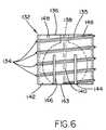
- FIG. 6is a side view of a coupling element of a plate assembly of an embodiment of the invention.
- FIG. 7is a partial side cross sectional view of an assembled embodiment of the invention.
- FIG. 8is a perspective view of a plate assembly of another embodiment of the invention.
- FIGS. 3 a, 3 b, 3 c, 3 d and 4illustrate elements of a plate assembly 100 of an embodiment of the invention.
- FIG. 3 aillustrates a top view of a first longitudinal plate 100 a of the plate assembly 100 .
- the first plate 100 ahas an end 102 defined by longitudinal prongs 102 a, 102 b that are laterally adjacent one another. While two prongs are shown in this embodiment, and are shown as laterally adjacent one another, it is understood that a greater number of prongs and/or prongs that are adjacent one another in other configurations can be used without departing from the scope of the invention.
- FIG. 3 billustrates a top view of a second longitudinal plate 100 b of the plate assembly 100 .
- the second plate 100 bhas an end 104 that has a longitudinal bore 104 a that is adapted to receive the prongs 102 a, 102 b for longitudinal translation therein through a plurality of positions.
- FIG. 4illustrates a top view of the plate assembly 100 when the prongs 102 a, 102 b of the first plate 100 a are received within the bore 104 a of the second plate 100 b.
- the prongs 102 a, 102 bcan be inserted into the bore 104 a and translated longitudinally therein through one or more of the plurality of positions until the desired length of the plate assembly 100 is achieved by stopping the translation at one of the positions, such position establishing the desired relative position of the first plate 100 a to the second plate 100 b to achieve the desired length of the plate assembly 100 .
- the plates 100 a, 100 bmay be constructed of any suitably biocompatible material which has the structural strength and durability to withstand the cyclical loading associated with long term fixation to the spine.
- Materials which would be suitable for such applicationsinclude titanium alloys and steels.
- a specific titanium material which has been utilized in implants of the prior artinclude ASTM F-136 titanium alloy (Ti 6AL-4V). This material has enhanced mechanical properties including fatigue endurance and tensile strength, as compared with pure titanium.
- the plate assembly 100further includes a lock assembly for locking the prongs 102 a, 102 b within the bore 104 a at the selected position. Activation of the lock assembly secures the relative position of the plates 100 a, 100 b so that the desired length of the plate assembly 100 is fixed.
- FIGS. 3 cillustrates an end view of the first plate 100 a.
- the lock assemblyincludes a threaded bore 100 d between the prongs 102 a, 102 b and a set screw 100 e passing between the prongs 102 a, 102 b and into the threaded bore 100 d.
- Rotation of the set screw 100 eadvances the set screw 100 e into the threaded bore 100 d, causing the prongs 102 a, 102 b to separate as the set screw 100 e passes between them as it advances.
- a head of the set screw 100 eincludes a recess that can be mated with a screwdriving tool and the screwdriving tool can be used to rotate the set screw 100 e within the threaded bore 100 d to advance the set screw 100 e until the prongs 102 a, 102 b separate.
- FIG. 3 dillustrates an end view of the second plate 100 b. It can be seen that the bore 104 a has an inner surface 104 b.
- FIG. 4illustrates a plan view of the plate assembly 100 when the prongs 102 a, 102 b are received within the bore 104 a.
- the prongs 102 a, 102 bare laterally adjacent one another and the lock assembly separates the prongs 102 a, 102 b to press them against the inner surface 104 b as described above.
- the compression of the prongs 102 a, 102 b against the inner surface 104 bsecures the position of the plates 100 a, 100 b relative to one another, thereby fixing the length of the plate assembly 100 .
- a slight lateral curvaturepreferably is imparted to the plate assembly 100 .
- the first plate 100 ahas a convex top surface 108 a and a concave bottom surface 109 a.
- the second plate 100 bhas a convex top surface 108 b and a concave bottom surface 109 b and the bore 104 a has a corresponding curvature so that it can receive the prongs 102 a, 102 b of the first plate 100 a.
- each plate 100 a, 100 bincludes a feature that can be used to couple the plate 100 a, 100 b to a body structure.
- each featurecomprises a pair of through holes.
- additional or alternative featuresmay be appropriate, including, for example, one or more hooks, rings, recesses, clips, and adhesives.
- a first pair of through holes 110extend fully through the first plate 100 a, from the top surface 108 a of the plate 100 a through to the bottom surface 109 a of the plate 100 a.
- a second pair of through holes 112having internal threading 113 , extend fully through the second plate 100 b, from the top surface 108 b of the plate 100 b through to the bottom surface 109 b of the plate 109 b.
- the embodiment shownfurther includes elements that can be used in conjunction with the features of the plates 100 a, 100 b to couple the plates 100 a, 100 b to the body structure.
- the elementsinclude screws and cooperative coupling elements. It should be understood that elements or tools other than the ones herein described can alternatively or additionally be used with the described or suggested features of the plates 100 a, 100 b to couple the plates 100 a, 100 b to the body structures.
- a screw of a type which is ideally suited for coupling the plates 100 a, 100 b to vertebral bonesis shown in a side view.
- the screw 120comprises a head portion 122 , a neck 124 , and a shaft 126 .
- the shaft 126is shown as having a tapered shape with a high pitch thread 128 .
- the specific choice of shaft features, such as thread pitch, or shaft diameter to thread diameter ratio, or overall shaft shape, etc.should be made by the physician with respect to the conditions of the patient's bone, however, the invention is compatible with a wide variety of shaft designs.
- the head portion 122 of the screw 120is semi-spherical and has a recess 130 . It is understood that the semi-spherical shape is necessarily a section of a sphere, greater in extent than a hemisphere, and exhibits an external contour which is equidistant from a center point of the head.
- the major cross-section of the semi-spherical head 122includes at least 270 degrees of a circle.
- the recess 130defines a receiving locus for the application of a torque for driving the screw 120 into the bone.
- the specific shape of the recess 122may be chosen to cooperate with any suitable screwdriving tool.
- the recess 130may comprise a slot for a flat-headed screwdriver, a crossed recess for a phillips head screwdriver, or most preferably, a hexagonally shaped hole for receiving an allen wrench.
- the recess 130be co-axial with the general elongate axis of the screw 120 , and most particularly with respect to the shaft 126 . Having the axes of the recess 130 and the shaft 126 co-linear facilitates step of inserting the screw 120 into the bone.
- the semi-spherical head 122is connected to the shaft 126 at a neck portion 124 . While it is preferable that the diameter of the shaft 126 be less than the radius of the semi-spherical head 122 , it is also preferable that the neck 124 of the screw 120 be narrower than the widest portion of the shaft 126 . This preferable dimension permits the screw to be inserted at a variety of angles while still permitting a coupling element (as described with respect to FIG. 6) to be screwed into the appropriate hole 110 or 112 of the plate assembly 100 and remain coupled to the head 122 .
- this embodimentfurther includes additional elements that can be used in conjunction with the features of the plates 100 a, 100 b to couple the plates 100 a, 100 b to the body structure or structures.
- a coupling element of the inventionis shown in side view, wherein phantom lines show the interior structure of the element along a diametrical cross section.
- the coupling element 132comprises a cylindrical socket having an external threading 134 .
- the external threading 134 and the diameter of the exterior of the cylindrical socketis designed to mate with threading 111 or 113 of the holes 110 or 112 of the plate assembly 100 , so that the coupling element 132 may be screwed into the plate assembly 100 .
- the uppermost thread 135be designed to crush-lock the coupling element 132 into the hole 110 or 112 . Once screwed into the plate assembly 100 , and locked down, the top surface 136 of the coupling element 132 and the respective top surface 108 a, 108 b of the plate assembly 100 present a flush external surface.
- the top surface 136 of the coupling element 132which is shown in FIG. 6 further comprises a through hole 138 , which extends from the top surface 136 to an interior semi-spherical volume 140 .
- This through hole 138is designed such that the screwdriving tool which is used to insert the screw 120 into the body structure may access and rotate the screw 120 through the coupling element 132 .
- the interior semi-spherical volume 140is ideally suited for holding the head 122 of the screw 120 , and permitting the screw 120 to rotate through a range of angles.
- the coupling element 132has a bottom 142 which has a circular hole (enumerated as 143 on the bottom surface of the side view of the coupling element in FIG. 6) which forms the bottom entrance into the interior semi-spherical volume 140 . It is understood that the head 122 of the screw 120 is held within the interior semi-spherical volume 140 by the annular rim, or support lip, 144 of the bottom 142 of the coupling element 132 . This annular support lip 144 defines the circular opening 143 which has a diameter less than the diameter of the semi-spherical head 122 of the screw 120 .
- the lower portion of the coupling element 132comprise slots 146 so that the physician may insert the head 122 into the interior volume 140 .
- These slots 146permit the lower portion of the coupling element 132 to expand to accept the inserted head 122 , but is secured from releasing the head 122 once the coupling element 132 is screwed into the plate assembly 100 .
- the holes 110 a or 112 a(as shown in phantom in FIG. 7) of the plate assembly 100 are tapered inward with respect to insertion direction.
- the step of screwing the coupling element 132 into the hole 110 a or 112 acauses the slots 146 to be compressed and, correspondingly, for the bottom entrance 143 and the annular lip 144 to lock the screw head 122 into position.
- the coupling element 132it is also possible for the coupling element 132 to be formed in a manner whereby the lower portion does not have to include an expanding entrance 143 .
- the coupling element 132would necessarily be formed of two separate pieces which would be joined together about the head 122 of the screw 120 .
- the top surface 136 of the coupling element 132it is preferred than the top surface 136 of the coupling element 132 have features, such as holes 148 , allowing a second screwdriving tool to easily insert the element 132 into the threaded holes 110 , 100 a or 112 , 112 a of the plate assembly 100 .
- FIG. 7a partial side cross sectional view of a plate assembly 100 of the invention is shown.
- the operative steps of implanting this plate assembly 100 and affixing it to, for example, a pair of vertebral bonesbegins with preparing the bones through surgical tissue resection and exposure.
- the prongs 102 a, 102 b of the first longitudinal plate 100 aare inserted into the bore 104 a of the second longitudinal plate 100 b and translated therein until the desired length of the plate assembly 100 is achieved. More specifically, the surgeon determines, after inspection of the vertebral bones to be secured, how far apart the holes 110 of the first longitudinal plate 100 a must be spaced from the holes 112 of the second longitudinal plate 100 b in order for the plate assembly 100 to be properly coupled to the vertebral bones to be clinically effective.
- the surgeonuses a screwdriving tool to rotate the set screw 100 e within the threaded bore 100 d to advance the set screw 100 e until the prongs 102 a, 102 b separate and press against the inner surface 104 b of the bore 104 a.
- the compression of the prongs 102 a, 102 b against the inner surface 104 bsecures the position of the plates 100 a, 100 b relative to one another, thereby fixing the length of the plate assembly 100 .
- the surgeonis able to use the screwdriving tool to rotate the set screw 100 e within the threaded bore 100 d to retract the set screw 100 e and thereby return the prongs 102 a, 102 b back together so that they no longer press against the inner surface 104 b of the bore 104 a so that the prongs 102 a, 102 b may again freely translate within the bore 104 a.
- This functionalityallows the surgeon to readjust the length of the plate assembly 100 if the surgeon's first setting of the length is not correct or is undesirable.
- the plate assembly 100is positioned against the bones and pre-drill holes are made at the desired insertion angle for the screw 120 .
- Screw 120 and coupling element 132are then placed together so that the head 122 is within the interior volume 140 , whereby the two elements are able to rotate freely with respect to one another, but are nonetheless coupled.
- the recess 130 in the screw 120 and the through hole 138 of the coupling element 132are aligned at first, and an appropriate screwdriving tool is used to insert the screw 120 through the proper hole 110 or 112 ( 110 a or 112 a ) and into the pre-drilled hole in the bone.
- an appropriate screwdriving toolis used to insert the screw 120 through the proper hole 110 or 112 ( 110 a or 112 a ) and into the pre-drilled hole in the bone.
- Complete insertion of the coupling element 132 to the plate assembly 100preferably locks the element 132 to the plate assembly 100 , in addition to locking the screw 120 and plate assembly 100 to the bone.
- corresponding holes 110 or 112may be tapered; the complete insertion of the coupling element 132 into the hole 110 or 112 therein having the additional benefit of locking the angle of the screw 120 .
- This plate assembly 300comprises a first plate 300 a corresponding to the first plate 100 a of the plate assembly 100 and a second plate 300 b corresponding to the second plate 100 b of the plate assembly 100 .
- the first plate 300 ahas through holes 310 and a bottom surface 309 a and the second plate 300 b has through holes 312 and a bottom surface 309 b.
- the plate assembly 300further includes at least one feature protruding from one of the bottom surfaces 309 a, 309 b for removable and temporary fixation of the plate assembly 300 to a vertebral bone.
- the featureis a spike.
- other featurescan additionally or alternatively be used to achieve this functionality without departing from the scope of the invention.
- one spike element 301protrudes from each of the bottom surfaces 309 a, 309 b.
- each spike 301is positioned between the pair of holes 310 or 312 , on center line A—A.
- These spikesallow the plate assembly 300 to be temporarily, and easily removably, fixed to vertebral bones during the steps of pre-drilling and insertion of the screws 120 through the holes 310 , 312 and into the vertebral bones. This is a desirable operational advantage, as it frees one hand of the surgeon and/or removes extra tools from the surgical site.
- the spikes 301positioned along the center line A—A for plate assemblies 300 which have a radius of curvature which is equal to or greater than that of the vertebral bodies such as, for example, vertebral bones (i.e., not as curved as the bone). Having the spikes 301 along the center line ensures that the plate assembly 300 can be removably fixed to the bone by simply applying an insertion force against the plate assembly 300 and driving the spikes 301 into the bone. It is understood that for implants wherein the plate assembly 300 has a smaller radius of curvature than the bone, it would be desirable to position the spikes 301 at edges 303 of the plate assembly 300 .
Landscapes
- Health & Medical Sciences (AREA)
- Orthopedic Medicine & Surgery (AREA)
- Life Sciences & Earth Sciences (AREA)
- Surgery (AREA)
- Neurology (AREA)
- Heart & Thoracic Surgery (AREA)
- Engineering & Computer Science (AREA)
- Biomedical Technology (AREA)
- Nuclear Medicine, Radiotherapy & Molecular Imaging (AREA)
- Medical Informatics (AREA)
- Molecular Biology (AREA)
- Animal Behavior & Ethology (AREA)
- General Health & Medical Sciences (AREA)
- Public Health (AREA)
- Veterinary Medicine (AREA)
- Prostheses (AREA)
- Surgical Instruments (AREA)
Abstract
Description
Claims (3)
Priority Applications (3)
| Application Number | Priority Date | Filing Date | Title |
|---|---|---|---|
| US09/789,938US6402756B1 (en) | 2001-02-15 | 2001-02-15 | Longitudinal plate assembly having an adjustable length |
| US10/075,689US6666867B2 (en) | 2001-02-15 | 2002-02-13 | Longitudinal plate assembly having an adjustable length |
| US10/725,307US20040106924A1 (en) | 2001-02-15 | 2003-12-01 | Longitudinal plate assembly having an adjustable length |
Applications Claiming Priority (1)
| Application Number | Priority Date | Filing Date | Title |
|---|---|---|---|
| US09/789,938US6402756B1 (en) | 2001-02-15 | 2001-02-15 | Longitudinal plate assembly having an adjustable length |
Related Child Applications (2)
| Application Number | Title | Priority Date | Filing Date |
|---|---|---|---|
| US10/075,689ContinuationUS6666867B2 (en) | 2001-02-15 | 2002-02-13 | Longitudinal plate assembly having an adjustable length |
| US10/075,689Continuation-In-PartUS6666867B2 (en) | 2001-02-15 | 2002-02-13 | Longitudinal plate assembly having an adjustable length |
Publications (1)
| Publication Number | Publication Date |
|---|---|
| US6402756B1true US6402756B1 (en) | 2002-06-11 |
Family
ID=25149164
Family Applications (1)
| Application Number | Title | Priority Date | Filing Date |
|---|---|---|---|
| US09/789,938Expired - LifetimeUS6402756B1 (en) | 2001-02-15 | 2001-02-15 | Longitudinal plate assembly having an adjustable length |
Country Status (1)
| Country | Link |
|---|---|
| US (1) | US6402756B1 (en) |
Cited By (191)
| Publication number | Priority date | Publication date | Assignee | Title |
|---|---|---|---|---|
| US20020183757A1 (en)* | 2001-06-04 | 2002-12-05 | Michelson Gary K. | Dynamic single-lock anterior cervical plate system having non-detachably fastened and moveable segments, instrumentation, and method for installation thereof |
| US20020183755A1 (en)* | 2001-06-04 | 2002-12-05 | Michelson Gary K. | Dynamic anterior cervical plate system having moveable segments, instrumentation, and method for installation thereof |
| US20020183754A1 (en)* | 2001-06-04 | 2002-12-05 | Michelson Gary K. | Anterior cervical plate system having vertebral body engaging anchors, connecting plate, and method for installation thereof |
| US20020188296A1 (en)* | 2001-06-06 | 2002-12-12 | Michelson Gary K. | Dynamic, modular, multilock anterior cervical plate system having detachably fastened assembleable and moveable segments, instrumentation, and method for installation thereof |
| US20030060828A1 (en)* | 2001-06-06 | 2003-03-27 | Michelson Gary K. | Dynamic multilock anterior cervical plate system having non-detachably fastened and moveable segments, instrumentation, and method for installation thereof |
| US6585738B1 (en)* | 1998-07-06 | 2003-07-01 | Stryker Spine | Spinal osteosynthesis device for anterior fixation with plate |
| US6599290B2 (en) | 2001-04-17 | 2003-07-29 | Ebi, L.P. | Anterior cervical plating system and associated method |
| US20030149434A1 (en)* | 2000-11-28 | 2003-08-07 | Paul Kamaljit S. | Bone support assembly |
| WO2003063714A3 (en)* | 2002-02-01 | 2003-09-04 | Spinal Concepts Inc | Spinal plate system for stabilizing a portion of a spine |
| US20030212399A1 (en)* | 2002-02-25 | 2003-11-13 | Dinh Dzung H. | Methods and apparatuses for promoting fusion of vertebrae |
| US20040010254A1 (en)* | 1999-09-03 | 2004-01-15 | Cook Daniel J. | Lumbar spine fixation device |
| WO2004008978A1 (en)* | 2002-07-24 | 2004-01-29 | Nas Spine, Inc. | Compressible fixation apparatus for spinal surgery |
| US6689134B2 (en)* | 2002-02-13 | 2004-02-10 | Third Millennium Engineering, Llc | Longitudinal plate assembly having an adjustable length |
| WO2003000148A3 (en)* | 2001-04-24 | 2004-02-12 | Windt Paul De | Fixing device for fixing vertebra parts |
| US20040030338A1 (en)* | 2001-12-14 | 2004-02-12 | Paul Kamaljit S. | Spinal plate assembly |
| US20040034354A1 (en)* | 2002-07-24 | 2004-02-19 | Paul Kamaljit S. | Bone support assembly |
| US20040097940A1 (en)* | 2001-12-14 | 2004-05-20 | Paul Kamaljit S. | Bone treatment plate assembly |
| US20040097925A1 (en)* | 2002-06-07 | 2004-05-20 | Boehm Frank H. | Cervical spine stabilizing system and method |
| US20040133207A1 (en)* | 2002-10-11 | 2004-07-08 | Abdou M. Samy | Distraction screw for skeletal surgery and method of use |
| US20040158250A1 (en)* | 2002-09-13 | 2004-08-12 | Chappuis James L. | Anterior cervical corpectomy plate |
| US20040181226A1 (en)* | 2001-06-04 | 2004-09-16 | Michelson Gary K. | Method for installing dynamic, modular, single-lock anterior cervical plate system having assembleable and moveable segments |
| US20040204712A1 (en)* | 2003-04-09 | 2004-10-14 | Eric Kolb | Bone fixation plates |
| US20040204713A1 (en)* | 2003-01-10 | 2004-10-14 | Abdou M. Samy | Plating system for bone fixation and subsidence and method of implantation |
| US20050010217A1 (en)* | 2003-07-07 | 2005-01-13 | Dalton Brian E. | Spinal stabilization implant and method of application |
| US20050010219A1 (en)* | 2003-07-07 | 2005-01-13 | Dalton Brain E. | Bone fixation assembly and method of securement |
| US20050010227A1 (en)* | 2000-11-28 | 2005-01-13 | Paul Kamaljit S. | Bone support plate assembly |
| US20050043732A1 (en)* | 2003-08-18 | 2005-02-24 | Dalton Brian E. | Cervical compression plate assembly |
| US20050049595A1 (en)* | 2003-09-03 | 2005-03-03 | Suh Sean S. | Track-plate carriage system |
| US20050059970A1 (en)* | 2003-09-17 | 2005-03-17 | Eric Kolb | Bone fixation systems |
| US20050137597A1 (en)* | 2003-12-22 | 2005-06-23 | Life Spine | Dynamic cervical plates and cervical plate constructs |
| US20050177160A1 (en)* | 2004-02-10 | 2005-08-11 | Baynham Bret O. | Dynamic cervical plate |
| US20050192580A1 (en)* | 2004-02-26 | 2005-09-01 | Dalton Brian E. | Polyaxial locking screw plate assembly |
| US20050228386A1 (en)* | 2004-04-08 | 2005-10-13 | Tara Ziolo | Bone fixation device |
| US20050277923A1 (en)* | 2004-06-09 | 2005-12-15 | Sweeney Patrick J | Spinal fixation system |
| US20050283155A1 (en)* | 2004-06-21 | 2005-12-22 | Michael Jacene | Instruments and methods for holding a bone plate |
| US20060116683A1 (en)* | 2004-12-01 | 2006-06-01 | Barrall Benjamin S | Unidirectional translation system for bone fixation |
| US20060122602A1 (en)* | 2004-12-08 | 2006-06-08 | Depuy Spine, Inc. | Hybrid spinal plates |
| US20060149245A1 (en)* | 2004-06-09 | 2006-07-06 | Spinal Generations, Llc | Bone fixation system |
| US20060149251A1 (en)* | 2004-12-22 | 2006-07-06 | Tara Ziolo | Bone fixation system |
| US20060167457A1 (en)* | 2005-01-21 | 2006-07-27 | Loubert Suddaby | Orthopedic fusion plate having both active and passive subsidence controlling features |
| US7090676B2 (en) | 2002-11-19 | 2006-08-15 | Acumed Llc | Adjustable bone plates |
| US20060179979A1 (en)* | 2005-02-01 | 2006-08-17 | Dees Roger R Jr | Lockable orientation stylus |
| US20060200134A1 (en)* | 2002-02-01 | 2006-09-07 | James Freid | Spinal plate system for stabilizing a portion of a spine |
| US20060235398A1 (en)* | 2005-04-05 | 2006-10-19 | Sdgi Holdings, Inc. | Ratcheting fixation plate |
| US20060271052A1 (en)* | 2005-05-12 | 2006-11-30 | Stern Joseph D | Revisable anterior cervical plating system |
| US7153309B2 (en) | 2002-11-19 | 2006-12-26 | Acumed Llc | Guide system for bone-repair devices |
| US20070010818A1 (en)* | 2005-07-06 | 2007-01-11 | Stone Howard A | Surgical system for joints |
| US20070035795A1 (en)* | 2005-08-04 | 2007-02-15 | Hubbard Jason R | Artificial facet joint and a method of making same |
| US7189237B2 (en) | 2002-11-19 | 2007-03-13 | Acumed Llc | Deformable bone plates |
| US20070073300A1 (en)* | 2005-09-26 | 2007-03-29 | Mohamed Attawia | Red light implant for treating osteoporosis |
| US20070083207A1 (en)* | 2005-09-21 | 2007-04-12 | Tara Ziolo | Variable angle bone fixation assembly |
| US20070100340A1 (en)* | 2005-10-27 | 2007-05-03 | Sdgi Holdings, Inc. | Intervertebral prosthetic device for spinal stabilization and method of implanting same |
| US20070173833A1 (en)* | 2006-01-10 | 2007-07-26 | Life Spine, Llc | Pedicle screw constructs and spinal rod attachment assemblies |
| US20070213729A1 (en)* | 2006-03-08 | 2007-09-13 | Sdgi Holdings, Inc. | Flexible bone plates and methods for dynamic spinal stabilization |
| US20070233117A1 (en)* | 2006-02-21 | 2007-10-04 | Life Spine, Llc | Structure for joining and retaining multi-part orthopedic implants |
| US7278997B1 (en) | 2003-03-07 | 2007-10-09 | Theken Spine, Llc | Instrument guide and implant holder |
| US20070276371A1 (en)* | 2004-02-10 | 2007-11-29 | Baynham Bret O | Dynamic cervical plate |
| US7306605B2 (en) | 2003-10-02 | 2007-12-11 | Zimmer Spine, Inc. | Anterior cervical plate |
| US20080033438A1 (en)* | 2006-08-04 | 2008-02-07 | Roy Frizzell | Cervical Saddle Plate |
| US20080051786A1 (en)* | 2006-04-03 | 2008-02-28 | Acumed Llc | Bone plates with hybrid apertures |
| US20080086131A1 (en)* | 2006-10-06 | 2008-04-10 | Depuy Spine, Inc. | Bone screw fixation |
| US20080108998A1 (en)* | 2006-11-02 | 2008-05-08 | Warsaw Orthopedic Inc. | Uni-directional ratcheting bone plate assembly |
| US20080140128A1 (en)* | 2006-12-08 | 2008-06-12 | Trimax Medical Management, Inc. | Sternal Closure Device and Method of Using Same |
| US20080147124A1 (en)* | 2006-10-31 | 2008-06-19 | Haidukewych George J | Bone plate system with slidable compression holes |
| US20080161861A1 (en)* | 2006-10-17 | 2008-07-03 | Acumed Llc | Bone fixation with a strut-stabilized bone plate |
| US20080172094A1 (en)* | 2001-12-24 | 2008-07-17 | Synthes (U.S.A) | Device for osteosynthesis |
| US20080177263A1 (en)* | 2006-10-24 | 2008-07-24 | Aesculap Implant Systems, Inc | Dynamic stabilization device for anterior lower lumbar vertebral fusion |
| US7416553B2 (en) | 2003-04-09 | 2008-08-26 | Depuy Acromed, Inc. | Drill guide and plate inserter |
| US20080221652A1 (en)* | 2005-09-26 | 2008-09-11 | Dimauro Thomas | Red Light Implants for Treating Degenerative Disc Disease |
| US20080234681A1 (en)* | 2004-02-10 | 2008-09-25 | Baynham Matthew G | Dynamic cervical plate |
| US20080243192A1 (en)* | 2007-03-27 | 2008-10-02 | Depuy Spine, Inc. | Passive Screw Locking Mechanism |
| US20080306550A1 (en)* | 2007-06-07 | 2008-12-11 | Matityahu Amir M | Spine repair assembly |
| US7476251B2 (en) | 2002-10-29 | 2009-01-13 | Kyphon Sarl | Interspinous process apparatus and method with a selectably expandable spacer |
| US20090076509A1 (en)* | 2007-09-13 | 2009-03-19 | Stryker Spine | Dynamic cervical plate |
| US7524324B2 (en) | 2004-04-28 | 2009-04-28 | Kyphon Sarl | System and method for an interspinous process implant as a supplement to a spine stabilization implant |
| US7537596B2 (en) | 2003-06-20 | 2009-05-26 | Acumed Llc | Bone plates with intraoperatively tapped apertures |
| US7537604B2 (en) | 2002-11-19 | 2009-05-26 | Acumed Llc | Bone plates with slots |
| US7537603B2 (en) | 2002-07-22 | 2009-05-26 | Acumed Llc | Bone fusion system |
| US7549999B2 (en) | 2003-05-22 | 2009-06-23 | Kyphon Sarl | Interspinous process distraction implant and method of implantation |
| US20090177237A1 (en)* | 2008-01-04 | 2009-07-09 | Spartek Medical, Inc. | Cervical spine implant system and method |
| US20090192553A1 (en)* | 2008-01-25 | 2009-07-30 | Depuy Spine, Inc. | Anti-backout mechanism |
| US20090210008A1 (en)* | 2008-02-20 | 2009-08-20 | Life Spine, Inc. | Modular spine plate with projection and socket interface |
| US7578825B2 (en) | 2004-04-19 | 2009-08-25 | Acumed Llc | Placement of fasteners into bone |
| US20090234359A1 (en)* | 2005-12-01 | 2009-09-17 | Hidetoshi Onoue | Mechanism for Osteosynthesis |
| US7591851B2 (en) | 2004-12-13 | 2009-09-22 | Kyphon Sarl | Inter-cervical facet implant and method |
| USD603508S1 (en) | 2008-07-03 | 2009-11-03 | Theken Spine, Llc | Cervical plate |
| USD603504S1 (en) | 2008-07-03 | 2009-11-03 | Theken Spine, Llc | Cervical plate |
| USD603511S1 (en) | 2008-07-03 | 2009-11-03 | Theken Spine, Llc | Cervical plate |
| USD603506S1 (en) | 2008-07-03 | 2009-11-03 | Theken Spine, Llc | Cervical plate |
| USD603507S1 (en) | 2008-07-03 | 2009-11-03 | Theken Spine, Llc | Cervical plate |
| USD603510S1 (en) | 2008-07-03 | 2009-11-03 | Theken Spine, Llc | Cervical plate |
| USD603509S1 (en) | 2008-07-03 | 2009-11-03 | Theken Spine, Llc | Cervical plate |
| USD603505S1 (en) | 2008-07-03 | 2009-11-03 | Theken Spine, Llc | Cervical plate |
| USD603503S1 (en) | 2008-07-03 | 2009-11-03 | Theken Spine, Llc | Cervical plate |
| USD603962S1 (en) | 2008-07-03 | 2009-11-10 | Theken Spine, Llc | Cervical plate |
| USD603961S1 (en) | 2008-07-03 | 2009-11-10 | Theken Spine, Llc | Cervical plate |
| USD603963S1 (en) | 2008-07-03 | 2009-11-10 | Theken Spine, Llc | Cervical plate |
| USD603964S1 (en) | 2008-07-03 | 2009-11-10 | Theken Spine, Llc | Cervical plate |
| US20090281571A1 (en)* | 2008-05-08 | 2009-11-12 | Aesculap Implant Systems, Inc. | Minimally invasive spinal stabilization system |
| US7621939B2 (en) | 1997-01-02 | 2009-11-24 | Kyphon Sarl | Supplemental spine fixation device and method |
| US20090299370A1 (en)* | 2008-05-29 | 2009-12-03 | Kiester P Douglas | Dynamization of fixed screw fracture plates |
| US7635365B2 (en) | 2003-08-28 | 2009-12-22 | Ellis Thomas J | Bone plates |
| US20100065714A1 (en)* | 2008-06-30 | 2010-03-18 | Dennis Ray Curlee | Chock apparatus |
| US20100076448A1 (en)* | 2003-12-29 | 2010-03-25 | Abdou M Samy | Plating system for bone fixation and method of implantation |
| US20100082067A1 (en)* | 2008-09-29 | 2010-04-01 | Kondrashov Dimitriy G | System and method to stablize a spinal column including a spinolaminar locking plate |
| US7717945B2 (en) | 2002-07-22 | 2010-05-18 | Acumed Llc | Orthopedic systems |
| US7727266B2 (en) | 2004-06-17 | 2010-06-01 | Warsaw Orthopedic, Inc. | Method and apparatus for retaining screws in a plate |
| US20100137909A1 (en)* | 2002-01-08 | 2010-06-03 | Osman Said G | Method for postoperatively compressing a bone graft |
| US20100145386A1 (en)* | 2007-09-19 | 2010-06-10 | Stout Medical, Inc. | Implantable support device and method of use |
| US7740649B2 (en) | 2004-02-26 | 2010-06-22 | Pioneer Surgical Technology, Inc. | Bone plate system and methods |
| US7749252B2 (en) | 2005-03-21 | 2010-07-06 | Kyphon Sarl | Interspinous process implant having deployable wing and method of implantation |
| US7758619B2 (en) | 1997-01-02 | 2010-07-20 | Kyphon SÀRL | Spinous process implant with tethers |
| US7763050B2 (en) | 2004-12-13 | 2010-07-27 | Warsaw Orthopedic, Inc. | Inter-cervical facet implant with locking screw and method |
| US7766947B2 (en) | 2001-10-31 | 2010-08-03 | Ortho Development Corporation | Cervical plate for stabilizing the human spine |
| US7766911B1 (en) | 2002-07-05 | 2010-08-03 | Theken Spine, Llc | Fixed and variable locking fixation assembly |
| US7776047B2 (en) | 2003-04-09 | 2010-08-17 | Depuy Spine, Inc. | Guide for spinal tools, implants, and devices |
| US20100217393A1 (en)* | 2009-02-20 | 2010-08-26 | Theofilos Charles S | Interbody fusion system with intervertebral implant retention assembly |
| US20100228291A1 (en)* | 2008-08-29 | 2010-09-09 | Butler Michael S | Single-Sided Dynamic Spine Plates |
| US20100234895A1 (en)* | 2009-03-13 | 2010-09-16 | Harold Hess | Dynamic Vertebral Column Plate System |
| US20100234888A1 (en)* | 2007-10-23 | 2010-09-16 | K2M, Inc. | Dynamic cervical plate |
| US20100234850A1 (en)* | 2005-02-01 | 2010-09-16 | Smith And Nephew, Inc. | Lockable Orientation Instrument Assembly |
| US7833246B2 (en) | 2002-10-29 | 2010-11-16 | Kyphon SÀRL | Interspinous process and sacrum implant and method |
| US20100292796A1 (en)* | 2009-05-14 | 2010-11-18 | Stout Medical Group, L.P. | Expandable support device and method of use |
| US20100312282A1 (en)* | 2005-02-18 | 2010-12-09 | Samy Abdou | Devices and methods for dynamic fixation of skeletal structure |
| US7909848B2 (en) | 2003-06-27 | 2011-03-22 | Depuy Spine, Inc. | Tissue retractor and guide device |
| US7909829B2 (en) | 2003-06-27 | 2011-03-22 | Depuy Spine, Inc. | Tissue retractor and drill guide |
| US7909853B2 (en) | 2004-09-23 | 2011-03-22 | Kyphon Sarl | Interspinous process implant including a binder and method of implantation |
| US7935123B2 (en) | 2003-04-09 | 2011-05-03 | Depuy Acromed, Inc. | Drill guide with alignment feature |
| US20110118784A1 (en)* | 2004-02-10 | 2011-05-19 | Baynham Bret O | Cervical Plate Ratchet Pedicle Screws |
| US20110137314A1 (en)* | 2009-07-06 | 2011-06-09 | Zimmer, Gmbh | Periprosthetic bone plates |
| US7959652B2 (en) | 2005-04-18 | 2011-06-14 | Kyphon Sarl | Interspinous process implant having deployable wings and method of implantation |
| US8012209B2 (en) | 2004-09-23 | 2011-09-06 | Kyphon Sarl | Interspinous process implant including a binder, binder aligner and method of implantation |
| US20110218534A1 (en)* | 2010-03-08 | 2011-09-08 | Bernard Prandi | Adjustable-angle radius plate |
| US20110218533A1 (en)* | 2010-03-08 | 2011-09-08 | Bernard Prandi | Radius-plate assembly |
| US8048117B2 (en) | 2003-05-22 | 2011-11-01 | Kyphon Sarl | Interspinous process implant and method of implantation |
| US8070778B2 (en) | 2003-05-22 | 2011-12-06 | Kyphon Sarl | Interspinous process implant with slide-in distraction piece and method of implantation |
| US8070749B2 (en) | 2005-05-12 | 2011-12-06 | Stern Joseph D | Revisable anterior cervical plating system |
| US8083795B2 (en) | 2006-01-18 | 2011-12-27 | Warsaw Orthopedic, Inc. | Intervertebral prosthetic device for spinal stabilization and method of manufacturing same |
| US8092494B2 (en) | 2004-01-13 | 2012-01-10 | Life Spine, Inc. | Pedicle screw constructs for spine fixation systems |
| US8172885B2 (en) | 2003-02-05 | 2012-05-08 | Pioneer Surgical Technology, Inc. | Bone plate system |
| US8177819B2 (en) | 2004-04-22 | 2012-05-15 | Acumed Llc | Expanded fixation of bones |
| US8361126B2 (en) | 2007-07-03 | 2013-01-29 | Pioneer Surgical Technology, Inc. | Bone plate system |
| US8388660B1 (en) | 2006-08-01 | 2013-03-05 | Samy Abdou | Devices and methods for superior fixation of orthopedic devices onto the vertebral column |
| US8425530B2 (en) | 2004-12-13 | 2013-04-23 | Warsaw Orthopedic, Inc. | Apparatus for sizing a facet joint |
| US8523861B2 (en) | 2010-08-30 | 2013-09-03 | Biomet Manufacturing, Llc | Method and apparatus for osteosynthesis |
| US8562656B2 (en) | 2010-10-15 | 2013-10-22 | Warsaw Orrthopedic, Inc. | Retaining mechanism |
| US8568417B2 (en) | 2009-12-18 | 2013-10-29 | Charles River Engineering Solutions And Technologies, Llc | Articulating tool and methods of using |
| US8574270B2 (en) | 2009-03-13 | 2013-11-05 | Spinal Simplicity Llc | Bone plate assembly with bone screw retention features |
| US8623019B2 (en) | 2007-07-03 | 2014-01-07 | Pioneer Surgical Technology, Inc. | Bone plate system |
| US20140012260A1 (en)* | 2012-07-09 | 2014-01-09 | The Cleveland Clinc Foundation | Bone fixation assembly |
| WO2014056058A1 (en)* | 2012-10-11 | 2014-04-17 | Angeli José Alberto | Diaphyseal and metaphyseal lengthener |
| CN104042317A (en)* | 2014-06-16 | 2014-09-17 | 姜永庆 | Spine fixing system |
| US8858603B1 (en) | 2010-06-09 | 2014-10-14 | Choice Spine, L.P. | Cervical plate with screw retention clip |
| US8900277B2 (en) | 2004-02-26 | 2014-12-02 | Pioneer Surgical Technology, Inc. | Bone plate system |
| US8974504B2 (en) | 2012-05-10 | 2015-03-10 | Spinal Simplicity Llc | Dynamic bone fracture plates |
| US9017412B2 (en) | 2011-04-29 | 2015-04-28 | Life Spine, Inc. | Spinal interbody implant with bone screw retention |
| US20150119992A1 (en)* | 2010-02-01 | 2015-04-30 | X-Spine Systems, Inc. | Spinal implant co-insertion system and method |
| US9028498B2 (en) | 2013-03-14 | 2015-05-12 | Innovasis, Inc. | Modular bone fixation plate assembly |
| USD734853S1 (en) | 2009-10-14 | 2015-07-21 | Nuvasive, Inc. | Bone plate |
| US9089343B2 (en) | 2005-10-03 | 2015-07-28 | Smith & Nephew, Inc. | Locking instrument assembly |
| US20150320452A1 (en)* | 2007-11-21 | 2015-11-12 | Globus Medical, Inc. | Cervical spine stabilization system with extendable plates |
| US9237910B2 (en) | 2012-01-26 | 2016-01-19 | Acute Innovations Llc | Clip for rib stabilization |
| US20160022319A1 (en)* | 2012-01-04 | 2016-01-28 | Warsaw Orthopedic, Inc. | System and method for correction of a spinal disorder |
| US9408646B2 (en) | 2003-09-03 | 2016-08-09 | DePuy Synthes Products, Inc. | Bone plate with captive clips |
| US9579128B2 (en) | 2013-07-19 | 2017-02-28 | K2M, Inc. | Translational plate and compressor instrument |
| US9615866B1 (en) | 2004-10-18 | 2017-04-11 | Nuvasive, Inc. | Surgical fixation system and related methods |
| US20170181779A1 (en)* | 2015-12-29 | 2017-06-29 | Orthohelix Surgical Designs, Inc. | Active compression plate and method for its use |
| GB2546089A (en)* | 2016-01-07 | 2017-07-12 | Veterinary Instr Ltd | A bone stabilisation device and uses thereof |
| US9775657B2 (en) | 2011-09-30 | 2017-10-03 | Acute Innovations Llc | Bone fixation system with opposed mounting portions |
| US9867714B1 (en) | 2011-09-23 | 2018-01-16 | Samy Abdou | Spinal fixation devices and methods of use |
| US9877759B2 (en) | 2014-02-06 | 2018-01-30 | Life Spine, Inc. | Foot implant for bone fixation |
| US9889014B2 (en) | 2014-02-06 | 2018-02-13 | Life Spine, Inc. | Implant for bone fixation |
| US9956015B2 (en) | 2014-07-03 | 2018-05-01 | Acumed Llc | Bone plate with movable joint |
| US10111757B2 (en) | 2012-10-22 | 2018-10-30 | Cogent Spine, LLC | Devices and methods for spinal stabilization and instrumentation |
| US10327910B2 (en) | 2013-03-14 | 2019-06-25 | X-Spine Systems, Inc. | Spinal implant and assembly |
| US10342583B2 (en) | 2010-10-01 | 2019-07-09 | K2M, Inc. | Dynamic plate with inserts |
| US10543107B2 (en) | 2009-12-07 | 2020-01-28 | Samy Abdou | Devices and methods for minimally invasive spinal stabilization and instrumentation |
| US10548740B1 (en) | 2016-10-25 | 2020-02-04 | Samy Abdou | Devices and methods for vertebral bone realignment |
| US10582955B2 (en) | 2017-03-22 | 2020-03-10 | Zavation, Llc | Methods of implanting bone plate assemblies |
| US10660677B2 (en) | 2017-03-22 | 2020-05-26 | Zavation Medical Products, Llc | Expandable bone plate assemblies |
| US10695105B2 (en) | 2012-08-28 | 2020-06-30 | Samy Abdou | Spinal fixation devices and methods of use |
| US10857003B1 (en) | 2015-10-14 | 2020-12-08 | Samy Abdou | Devices and methods for vertebral stabilization |
| US10918498B2 (en) | 2004-11-24 | 2021-02-16 | Samy Abdou | Devices and methods for inter-vertebral orthopedic device placement |
| US10973648B1 (en) | 2016-10-25 | 2021-04-13 | Samy Abdou | Devices and methods for vertebral bone realignment |
| US11006982B2 (en) | 2012-02-22 | 2021-05-18 | Samy Abdou | Spinous process fixation devices and methods of use |
| US11123117B1 (en)* | 2011-11-01 | 2021-09-21 | Nuvasive, Inc. | Surgical fixation system and related methods |
| US11179248B2 (en) | 2018-10-02 | 2021-11-23 | Samy Abdou | Devices and methods for spinal implantation |
| US11331125B1 (en)* | 2021-10-07 | 2022-05-17 | Ortho Inventions, Llc | Low profile rod-to-rod coupler |
| US11877779B2 (en) | 2020-03-26 | 2024-01-23 | Xtant Medical Holdings, Inc. | Bone plate system |
| US20240382317A1 (en)* | 2023-05-16 | 2024-11-21 | Globus Medical, Inc. | Modular lateral plating system and related methods |
| US12285197B2 (en) | 2008-10-10 | 2025-04-29 | Acumed Llc | Bone fixation system with opposed mounting portions |
Citations (6)
| Publication number | Priority date | Publication date | Assignee | Title |
|---|---|---|---|---|
| US5520690A (en)* | 1995-04-13 | 1996-05-28 | Errico; Joseph P. | Anterior spinal polyaxial locking screw plate assembly |
| US5531747A (en)* | 1993-03-11 | 1996-07-02 | Danek Medical Inc. | System for stabilizing the spine and reducing spondylolisthesis |
| US5616142A (en)* | 1994-07-20 | 1997-04-01 | Yuan; Hansen A. | Vertebral auxiliary fixation device |
| US5681313A (en)* | 1995-02-06 | 1997-10-28 | Karl Leibinger Medizintechnik Gmbh & Co. Kg | Device for the extension of bones |
| US5964763A (en)* | 1997-02-14 | 1999-10-12 | Incavo; Stephen J. | Incrementally adjustable tibial osteotomy fixation device and method |
| US6139316A (en)* | 1999-01-26 | 2000-10-31 | Sachdeva; Rohit C. L. | Device for bone distraction and tooth movement |
- 2001
- 2001-02-15USUS09/789,938patent/US6402756B1/ennot_activeExpired - Lifetime
Patent Citations (8)
| Publication number | Priority date | Publication date | Assignee | Title |
|---|---|---|---|---|
| US5531747A (en)* | 1993-03-11 | 1996-07-02 | Danek Medical Inc. | System for stabilizing the spine and reducing spondylolisthesis |
| US5616142A (en)* | 1994-07-20 | 1997-04-01 | Yuan; Hansen A. | Vertebral auxiliary fixation device |
| US5681313A (en)* | 1995-02-06 | 1997-10-28 | Karl Leibinger Medizintechnik Gmbh & Co. Kg | Device for the extension of bones |
| US5520690A (en)* | 1995-04-13 | 1996-05-28 | Errico; Joseph P. | Anterior spinal polyaxial locking screw plate assembly |
| US5531746A (en)* | 1995-04-13 | 1996-07-02 | Fastenetix, L.L.C. | Posterior spinal polyaxial locking lateral mass screw plate assembly |
| US5643265A (en)* | 1995-04-13 | 1997-07-01 | Fastenetix, L.L.C. | Dynamic compression polyaxial locking screw plate assembly |
| US5964763A (en)* | 1997-02-14 | 1999-10-12 | Incavo; Stephen J. | Incrementally adjustable tibial osteotomy fixation device and method |
| US6139316A (en)* | 1999-01-26 | 2000-10-31 | Sachdeva; Rohit C. L. | Device for bone distraction and tooth movement |
Cited By (427)
| Publication number | Priority date | Publication date | Assignee | Title |
|---|---|---|---|---|
| US7828822B2 (en) | 1997-01-02 | 2010-11-09 | Kyphon SÀRL | Spinous process implant |
| US7918877B2 (en) | 1997-01-02 | 2011-04-05 | Kyphon Sarl | Lateral insertion method for spinous process spacer with deployable member |
| US7955356B2 (en) | 1997-01-02 | 2011-06-07 | Kyphon Sarl | Laterally insertable interspinous process implant |
| US7621939B2 (en) | 1997-01-02 | 2009-11-24 | Kyphon Sarl | Supplemental spine fixation device and method |
| US7758619B2 (en) | 1997-01-02 | 2010-07-20 | Kyphon SÀRL | Spinous process implant with tethers |
| US6585738B1 (en)* | 1998-07-06 | 2003-07-01 | Stryker Spine | Spinal osteosynthesis device for anterior fixation with plate |
| US7135024B2 (en) | 1999-09-03 | 2006-11-14 | Cookgas, L.L.C. | Lumbar spine fixation device |
| US20040010254A1 (en)* | 1999-09-03 | 2004-01-15 | Cook Daniel J. | Lumbar spine fixation device |
| US20050216011A1 (en)* | 2000-11-28 | 2005-09-29 | Paul Kamaljit S | Bone support plate assembly |
| US20030149434A1 (en)* | 2000-11-28 | 2003-08-07 | Paul Kamaljit S. | Bone support assembly |
| US7727265B2 (en) | 2000-11-28 | 2010-06-01 | Paul Kamaljit S | Bone support plate assembly |
| US20050010227A1 (en)* | 2000-11-28 | 2005-01-13 | Paul Kamaljit S. | Bone support plate assembly |
| US20040106924A1 (en)* | 2001-02-15 | 2004-06-03 | Ralph James D. | Longitudinal plate assembly having an adjustable length |
| US6599290B2 (en) | 2001-04-17 | 2003-07-29 | Ebi, L.P. | Anterior cervical plating system and associated method |
| US20040167521A1 (en)* | 2001-04-24 | 2004-08-26 | Paul De Windt | Fixing device for fixing vertebra parts |
| WO2003000148A3 (en)* | 2001-04-24 | 2004-02-12 | Windt Paul De | Fixing device for fixing vertebra parts |
| US20110054528A1 (en)* | 2001-06-04 | 2011-03-03 | Michelson Gary K | Dynamic plate system having moveable segments |
| US7824432B2 (en) | 2001-06-04 | 2010-11-02 | Warsaw Orthopedic, Inc. | Method for installation of dynamic anterior cervical plate system having moveable segments |
| US20020183757A1 (en)* | 2001-06-04 | 2002-12-05 | Michelson Gary K. | Dynamic single-lock anterior cervical plate system having non-detachably fastened and moveable segments, instrumentation, and method for installation thereof |
| US7547306B2 (en) | 2001-06-04 | 2009-06-16 | Warsaw Orthopedic, Inc. | Method for installation of dynamic, single-lock anterior cervical plate system having non-detachably fastened and moveable segments |
| US20090259226A1 (en)* | 2001-06-04 | 2009-10-15 | Michelson Gary K | Method for installation of dynamic, single-lock anterior cervical plate system having non-detachably fastened and moveable segments |
| US7399301B2 (en) | 2001-06-04 | 2008-07-15 | Warsaw Orthopedic, Inc. | Instrumentation for use with dynamic single-lock anterior cervical plate system having non-detachably fastened and moveable segments |
| US20020183755A1 (en)* | 2001-06-04 | 2002-12-05 | Michelson Gary K. | Dynamic anterior cervical plate system having moveable segments, instrumentation, and method for installation thereof |
| US20050216010A1 (en)* | 2001-06-04 | 2005-09-29 | Michelson Gary K | Method for installation of dynamic, single-lock anterior cervical plate system having non-detachably fastened and moveable segments |
| US7186256B2 (en) | 2001-06-04 | 2007-03-06 | Warsaw Orthopedic, Inc. | Dynamic, modular, single-lock anterior cervical plate system having assembleable and movable segments |
| US20020183754A1 (en)* | 2001-06-04 | 2002-12-05 | Michelson Gary K. | Anterior cervical plate system having vertebral body engaging anchors, connecting plate, and method for installation thereof |
| WO2002098276A3 (en)* | 2001-06-04 | 2003-11-20 | Gary K Michelson | Dynamic anterior cervical plate system having moveable segments, instrumentation, and method for installation thereof |
| US20040181226A1 (en)* | 2001-06-04 | 2004-09-16 | Michelson Gary K. | Method for installing dynamic, modular, single-lock anterior cervical plate system having assembleable and moveable segments |
| US20040181229A1 (en)* | 2001-06-04 | 2004-09-16 | Michelson Gary K. | Instrumentation for use with dynamic single-lock anterior cervical plate system having non-detachably fastened and moveable segments |
| US20050085816A1 (en)* | 2001-06-04 | 2005-04-21 | Michelson Gary K. | Method for installation of dynamic anterior cervical plate system having moveable segments |
| US7740630B2 (en) | 2001-06-04 | 2010-06-22 | Warsaw Orthopedic, Inc. | Anterior cervical plate system having vertebral body engaging anchors and connecting plate |
| US7118573B2 (en) | 2001-06-04 | 2006-10-10 | Sdgi Holdings, Inc. | Dynamic anterior cervical plate system having moveable segments, instrumentation, and method for installation thereof |
| US7985224B2 (en) | 2001-06-04 | 2011-07-26 | Warsaw Orthopedic, Inc. | Method for installation of dynamic, single-lock anterior cervical plate system having non-detachably fastened and moveable segments |
| US8834533B2 (en) | 2001-06-04 | 2014-09-16 | Warsaw Orthopedic, Inc. | Dynamic plate system having moveable segments |
| US7112202B2 (en) | 2001-06-04 | 2006-09-26 | Warsaw Orthopedic, Inc. | Method for installing dynamic, modular, single-lock anterior cervical plate system having assembleable and moveable segments |
| US7097645B2 (en)* | 2001-06-04 | 2006-08-29 | Sdgi Holdings, Inc. | Dynamic single-lock anterior cervical plate system having non-detachably fastened and moveable segments |
| US20050187554A1 (en)* | 2001-06-04 | 2005-08-25 | Michelson Gary K. | Method for installation of anterior cervical plate system having vertebral body engaging anchors and connecting plate |
| US20050027297A1 (en)* | 2001-06-04 | 2005-02-03 | Michelson Gary K. | Dynamic, modular, single-lock anterior cervical plate system having assembleable and moveable segments and instrumentation for installation thereof |
| US8323283B2 (en) | 2001-06-04 | 2012-12-04 | Warsaw Orthopedic, Inc. | Plate system having bone portion engaging anchors and connecting plate |
| US7811285B2 (en)* | 2001-06-04 | 2010-10-12 | Warsaw Orthopedic, Inc. | Dynamic, modular, single-lock anterior cervical plate system having assembleable and moveable segments and instrumentation for installation thereof |
| US8048076B2 (en) | 2001-06-04 | 2011-11-01 | Warsaw Orthopedic, Inc. | Method for installation of anterior cervical plate system having vertebral body engaging anchors and connecting plate |
| US20020188296A1 (en)* | 2001-06-06 | 2002-12-12 | Michelson Gary K. | Dynamic, modular, multilock anterior cervical plate system having detachably fastened assembleable and moveable segments, instrumentation, and method for installation thereof |
| US7041105B2 (en) | 2001-06-06 | 2006-05-09 | Sdgi Holdings, Inc. | Dynamic, modular, multilock anterior cervical plate system having detachably fastened assembleable and moveable segments |
| US7044952B2 (en)* | 2001-06-06 | 2006-05-16 | Sdgi Holdings, Inc. | Dynamic multilock anterior cervical plate system having non-detachably fastened and moveable segments |
| US7803157B2 (en)* | 2001-06-06 | 2010-09-28 | Warsaw Orthopedic, Inc. | Dynamic, modular, multilock anterior cervical plate system having detachably fastened assembleable and moveable segments and instrumentation for installation thereof |
| US20050027298A1 (en)* | 2001-06-06 | 2005-02-03 | Michelson Gary K. | Dynamic, modular, multilock anterior cervical plate system having detachably fastened assembleable and moveable segments and instrumentation for installation thereof |
| US20030060828A1 (en)* | 2001-06-06 | 2003-03-27 | Michelson Gary K. | Dynamic multilock anterior cervical plate system having non-detachably fastened and moveable segments, instrumentation, and method for installation thereof |
| US7115130B2 (en) | 2001-06-06 | 2006-10-03 | Warsaw Orthopedic, Inc. | Method for installing dynamic, modular, multilock anterior cervical plate system having detachably fastened assembleable and moveable segments |
| US20050192576A1 (en)* | 2001-06-06 | 2005-09-01 | Michelson Gary K. | Method for installing dynamic multilock anterior cervical plate system having detachably fastened and moveable segments |
| US20040186476A1 (en)* | 2001-06-06 | 2004-09-23 | Michelson Gary K. | Method for installing dynamic, modular, multilock anterior cervical plate system having detachably fastened assembleable and moveable segments |
| US20050216009A1 (en)* | 2001-06-06 | 2005-09-29 | Michelson Gary K | Instrumentation for use with dynamic multilock anterior cervical plate system having non-detachably fastened and moveable segments |
| US7704250B2 (en) | 2001-06-06 | 2010-04-27 | Warsaw Orthopedic, Inc. | Instrumentation for use with dynamic multilock anterior cervical plate system having non-detachably fastened and moveable segments |
| US7621943B2 (en) | 2001-06-06 | 2009-11-24 | Warsaw Orthopedic, Inc. | Method for installing dynamic multilock anterior cervical plate system having detachably fastened and moveable segments |
| US7766947B2 (en) | 2001-10-31 | 2010-08-03 | Ortho Development Corporation | Cervical plate for stabilizing the human spine |
| US8236033B2 (en) | 2001-12-14 | 2012-08-07 | Paul Kamaljit S | Spinal plate assembly |
| US20060142768A1 (en)* | 2001-12-14 | 2006-06-29 | Paul Kamaljit S | Bone treatment plate assembly |
| US20040153069A1 (en)* | 2001-12-14 | 2004-08-05 | Paul Kamaljit S. | Spinal plate assembly |
| US7204837B2 (en) | 2001-12-14 | 2007-04-17 | Paul Kamaljit S | Spinal plate assembly |
| US6755833B1 (en) | 2001-12-14 | 2004-06-29 | Kamaljit S. Paul | Bone support assembly |
| US20040030338A1 (en)* | 2001-12-14 | 2004-02-12 | Paul Kamaljit S. | Spinal plate assembly |
| US7255699B2 (en) | 2001-12-14 | 2007-08-14 | Paul Kamaljit S | Spinal plate assembly |
| US7008426B2 (en) | 2001-12-14 | 2006-03-07 | Paul Kamaljit S | Bone treatment plate assembly |
| US20040097940A1 (en)* | 2001-12-14 | 2004-05-20 | Paul Kamaljit S. | Bone treatment plate assembly |
| US8128668B2 (en) | 2001-12-14 | 2012-03-06 | Paul Kamaljit S | Bone treatment plate assembly |
| US8221476B2 (en) | 2001-12-14 | 2012-07-17 | Paul Kamaljit S | Spinal plate assembly |
| US7794482B2 (en) | 2001-12-24 | 2010-09-14 | Synthes Usa, Llc | Device for osteosynthesis |
| US20080172094A1 (en)* | 2001-12-24 | 2008-07-17 | Synthes (U.S.A) | Device for osteosynthesis |
| US20100137909A1 (en)* | 2002-01-08 | 2010-06-03 | Osman Said G | Method for postoperatively compressing a bone graft |
| US8002810B2 (en) | 2002-01-08 | 2011-08-23 | Zimmer Spine, Inc. | Method for postoperatively compressing a bone graft |
| AU2003208956B8 (en)* | 2002-02-01 | 2009-03-26 | Zimmer Spine, Inc. | Spinal plate system for stabilizing a portion of a spine |
| AU2003208956B2 (en)* | 2002-02-01 | 2009-02-26 | Zimmer Spine, Inc. | Spinal plate system for stabilizing a portion of a spine |
| US8128628B2 (en) | 2002-02-01 | 2012-03-06 | Zimmer Spine, Inc. | Spinal plate system for stabilizing a portion of a spine |
| WO2003063714A3 (en)* | 2002-02-01 | 2003-09-04 | Spinal Concepts Inc | Spinal plate system for stabilizing a portion of a spine |
| US20080065070A1 (en)* | 2002-02-01 | 2008-03-13 | Freid James M | Spinal plate system for stabilizing a portion of a spine |
| US8814869B2 (en) | 2002-02-01 | 2014-08-26 | Zimmer Spine, Inc. | Spinal plate system for stabilizing a portion of a spine |
| US20060200134A1 (en)* | 2002-02-01 | 2006-09-07 | James Freid | Spinal plate system for stabilizing a portion of a spine |
| US20040019353A1 (en)* | 2002-02-01 | 2004-01-29 | Freid James M. | Spinal plate system for stabilizing a portion of a spine |
| US9101422B2 (en) | 2002-02-01 | 2015-08-11 | Zimmer Spine, Inc. | Spinal plate system for stabilizing a portion of a spine |
| US6689134B2 (en)* | 2002-02-13 | 2004-02-10 | Third Millennium Engineering, Llc | Longitudinal plate assembly having an adjustable length |
| US7186254B2 (en)* | 2002-02-25 | 2007-03-06 | Dinh Dzung H | Methods and apparatus for promoting fusion of vertebrae |
| US20030212399A1 (en)* | 2002-02-25 | 2003-11-13 | Dinh Dzung H. | Methods and apparatuses for promoting fusion of vertebrae |
| US20040097925A1 (en)* | 2002-06-07 | 2004-05-20 | Boehm Frank H. | Cervical spine stabilizing system and method |
| US7766911B1 (en) | 2002-07-05 | 2010-08-03 | Theken Spine, Llc | Fixed and variable locking fixation assembly |
| US7780666B1 (en) | 2002-07-05 | 2010-08-24 | Theken Spine, Llc | Fixed and variable locking fixation assembly |
| US7785327B1 (en) | 2002-07-05 | 2010-08-31 | Theken Spine, Llc | Fixed and variable locking fixation assembly |
| US9308033B2 (en) | 2002-07-22 | 2016-04-12 | Acumed Llc | Adjustable bone plates |
| US10456180B2 (en) | 2002-07-22 | 2019-10-29 | Acumed Llc | Adjustable bone plates |
| US7537603B2 (en) | 2002-07-22 | 2009-05-26 | Acumed Llc | Bone fusion system |
| US7717945B2 (en) | 2002-07-22 | 2010-05-18 | Acumed Llc | Orthopedic systems |
| US8425574B2 (en) | 2002-07-22 | 2013-04-23 | Acumed, Llc | Bone fixation with a bone plate attached to a fastener assembly |
| US7070599B2 (en) | 2002-07-24 | 2006-07-04 | Paul Kamaljit S | Bone support assembly |
| US7214226B2 (en)* | 2002-07-24 | 2007-05-08 | Nas Spine, Inc. | Compressible fixation apparatus for spinal surgery |
| US20040097938A1 (en)* | 2002-07-24 | 2004-05-20 | Neville Alleyne | Compressible fixation apparatus for spinal surgery |
| WO2004008978A1 (en)* | 2002-07-24 | 2004-01-29 | Nas Spine, Inc. | Compressible fixation apparatus for spinal surgery |
| US20040034354A1 (en)* | 2002-07-24 | 2004-02-19 | Paul Kamaljit S. | Bone support assembly |
| US20070288010A1 (en)* | 2002-07-24 | 2007-12-13 | Nas Spine, Inc. | Compressible fixation apparatus for spinal surgery |
| US20040158250A1 (en)* | 2002-09-13 | 2004-08-12 | Chappuis James L. | Anterior cervical corpectomy plate |
| US7476228B2 (en) | 2002-10-11 | 2009-01-13 | Abdou M Samy | Distraction screw for skeletal surgery and method of use |
| US20040133207A1 (en)* | 2002-10-11 | 2004-07-08 | Abdou M. Samy | Distraction screw for skeletal surgery and method of use |
| US20090177238A1 (en)* | 2002-10-11 | 2009-07-09 | Abdou M Samy | Distraction screw for skeletal surgery and method of use |
| US7833246B2 (en) | 2002-10-29 | 2010-11-16 | Kyphon SÀRL | Interspinous process and sacrum implant and method |
| US7476251B2 (en) | 2002-10-29 | 2009-01-13 | Kyphon Sarl | Interspinous process apparatus and method with a selectably expandable spacer |
| US7803190B2 (en) | 2002-10-29 | 2010-09-28 | Kyphon SÀRL | Interspinous process apparatus and method with a selectably expandable spacer |
| US7537604B2 (en) | 2002-11-19 | 2009-05-26 | Acumed Llc | Bone plates with slots |
| US7326212B2 (en) | 2002-11-19 | 2008-02-05 | Acumed Llc | Bone plates with reference marks |
| US7189237B2 (en) | 2002-11-19 | 2007-03-13 | Acumed Llc | Deformable bone plates |
| US7153309B2 (en) | 2002-11-19 | 2006-12-26 | Acumed Llc | Guide system for bone-repair devices |
| US7704251B2 (en) | 2002-11-19 | 2010-04-27 | Acumed Llc | Adjustable bone plates |
| US7090676B2 (en) | 2002-11-19 | 2006-08-15 | Acumed Llc | Adjustable bone plates |
| US20080058810A1 (en)* | 2003-01-10 | 2008-03-06 | Abdou M S | Bone screw systems and methods of use |
| US20040204713A1 (en)* | 2003-01-10 | 2004-10-14 | Abdou M. Samy | Plating system for bone fixation and subsidence and method of implantation |
| US7331961B2 (en) | 2003-01-10 | 2008-02-19 | Abdou M Samy | Plating system for bone fixation and subsidence and method of implantation |
| US8172885B2 (en) | 2003-02-05 | 2012-05-08 | Pioneer Surgical Technology, Inc. | Bone plate system |
| US7278997B1 (en) | 2003-03-07 | 2007-10-09 | Theken Spine, Llc | Instrument guide and implant holder |
| US7935123B2 (en) | 2003-04-09 | 2011-05-03 | Depuy Acromed, Inc. | Drill guide with alignment feature |
| US8394107B2 (en) | 2003-04-09 | 2013-03-12 | Depuy Spine, Inc. | Guide for spinal tools, implants, and devices |
| US20040204712A1 (en)* | 2003-04-09 | 2004-10-14 | Eric Kolb | Bone fixation plates |
| US7416553B2 (en) | 2003-04-09 | 2008-08-26 | Depuy Acromed, Inc. | Drill guide and plate inserter |
| US7776047B2 (en) | 2003-04-09 | 2010-08-17 | Depuy Spine, Inc. | Guide for spinal tools, implants, and devices |
| US7695513B2 (en) | 2003-05-22 | 2010-04-13 | Kyphon Sarl | Distractible interspinous process implant and method of implantation |
| US8070778B2 (en) | 2003-05-22 | 2011-12-06 | Kyphon Sarl | Interspinous process implant with slide-in distraction piece and method of implantation |
| US7549999B2 (en) | 2003-05-22 | 2009-06-23 | Kyphon Sarl | Interspinous process distraction implant and method of implantation |
| US8048117B2 (en) | 2003-05-22 | 2011-11-01 | Kyphon Sarl | Interspinous process implant and method of implantation |
| US7537596B2 (en) | 2003-06-20 | 2009-05-26 | Acumed Llc | Bone plates with intraoperatively tapped apertures |
| US7909848B2 (en) | 2003-06-27 | 2011-03-22 | Depuy Spine, Inc. | Tissue retractor and guide device |
| US7909829B2 (en) | 2003-06-27 | 2011-03-22 | Depuy Spine, Inc. | Tissue retractor and drill guide |
| US20050010217A1 (en)* | 2003-07-07 | 2005-01-13 | Dalton Brian E. | Spinal stabilization implant and method of application |
| US8211145B2 (en)* | 2003-07-07 | 2012-07-03 | Aesculap, Inc. | Spinal stabilization implant and method of application |
| US20050010218A1 (en)* | 2003-07-07 | 2005-01-13 | Dalton Brian E. | Bone fixation assembly and method of securement |
| WO2005009259A1 (en)* | 2003-07-07 | 2005-02-03 | Dalton Brian E | Spinal stabilization implant and method of application |
| US20080140129A1 (en)* | 2003-07-07 | 2008-06-12 | Aesculap Implant Systems, Inc. | Spinal stabilization implant and method of application |
| US6945974B2 (en) | 2003-07-07 | 2005-09-20 | Aesculap Inc. | Spinal stabilization implant and method of application |
| US20050267474A1 (en)* | 2003-07-07 | 2005-12-01 | Dalton Brian E | Bone fixation assembly and method of securement |
| US6945975B2 (en) | 2003-07-07 | 2005-09-20 | Aesculap, Inc. | Bone fixation assembly and method of securement |
| US20050010219A1 (en)* | 2003-07-07 | 2005-01-13 | Dalton Brain E. | Bone fixation assembly and method of securement |
| US20050010221A1 (en)* | 2003-07-07 | 2005-01-13 | Dalton Brian E. | Spinal stabilization implant and method of application |
| US6979334B2 (en) | 2003-07-07 | 2005-12-27 | Aesculap, Inc. | Bone fixation assembly and method of securement |
| WO2005018419A3 (en)* | 2003-08-18 | 2005-12-08 | Brian E Dalton | Cervical compression plate assembly |
| US7763056B2 (en) | 2003-08-18 | 2010-07-27 | Dalton Brian E | Cervical compression plate assembly |
| US20050043732A1 (en)* | 2003-08-18 | 2005-02-24 | Dalton Brian E. | Cervical compression plate assembly |
| US8632573B2 (en) | 2003-08-28 | 2014-01-21 | Thomas J. Ellis | Bone fixation system |
| US7635365B2 (en) | 2003-08-28 | 2009-12-22 | Ellis Thomas J | Bone plates |
| US7695501B2 (en) | 2003-08-28 | 2010-04-13 | Ellis Thomas J | Bone fixation system |
| US10368927B2 (en) | 2003-09-03 | 2019-08-06 | DePuy Synthes Products, Inc. | Bone plate with captive clips |
| US7666185B2 (en) | 2003-09-03 | 2010-02-23 | Synthes Usa, Llc | Translatable carriage fixation system |
| US9408646B2 (en) | 2003-09-03 | 2016-08-09 | DePuy Synthes Products, Inc. | Bone plate with captive clips |
| US20050049595A1 (en)* | 2003-09-03 | 2005-03-03 | Suh Sean S. | Track-plate carriage system |
| US9414870B2 (en) | 2003-09-03 | 2016-08-16 | DePuy Synthes Products, Inc. | Translatable carriage fixation system |
| US20060079901A1 (en)* | 2003-09-03 | 2006-04-13 | Ryan Christopher J | Translatable carriage fixation system |
| US8262659B2 (en) | 2003-09-03 | 2012-09-11 | Synthes Usa, Llc | Translatable carriage fixation system |
| US20050059970A1 (en)* | 2003-09-17 | 2005-03-17 | Eric Kolb | Bone fixation systems |
| US7306605B2 (en) | 2003-10-02 | 2007-12-11 | Zimmer Spine, Inc. | Anterior cervical plate |
| US8470006B2 (en) | 2003-10-22 | 2013-06-25 | Kamaljit S. Paul | Bone repair systems |
| CN100435743C (en)* | 2003-12-09 | 2008-11-26 | 埃斯库拉普公司 | Bone fixation assembly and method of securement |
| US7318825B2 (en) | 2003-12-22 | 2008-01-15 | Life Spine Llc | Dynamic cervical plates and cervical plate constructs |
| US8182518B2 (en) | 2003-12-22 | 2012-05-22 | Life Spine, Inc. | Static and dynamic cervical plates and cervical plate constructs |
| US20050149026A1 (en)* | 2003-12-22 | 2005-07-07 | Life Spine | Static & dynamic cervical plates and cervical plate constructs |
| US20050137597A1 (en)* | 2003-12-22 | 2005-06-23 | Life Spine | Dynamic cervical plates and cervical plate constructs |
| US20080114361A1 (en)* | 2003-12-22 | 2008-05-15 | Life Spine Llc | Dynamic cervical plates and cervical plate constructs |
| US20100076448A1 (en)* | 2003-12-29 | 2010-03-25 | Abdou M Samy | Plating system for bone fixation and method of implantation |
| US8092494B2 (en) | 2004-01-13 | 2012-01-10 | Life Spine, Inc. | Pedicle screw constructs for spine fixation systems |
| US7815666B2 (en) | 2004-02-10 | 2010-10-19 | Atlas Spine, Inc. | Dynamic cervical plate |
| US8328854B2 (en) | 2004-02-10 | 2012-12-11 | Atlas Spine, Inc. | Cervical plate ratchet pedicle screws |
| US20070276371A1 (en)* | 2004-02-10 | 2007-11-29 | Baynham Bret O | Dynamic cervical plate |
| US20110118784A1 (en)* | 2004-02-10 | 2011-05-19 | Baynham Bret O | Cervical Plate Ratchet Pedicle Screws |
| US20080234681A1 (en)* | 2004-02-10 | 2008-09-25 | Baynham Matthew G | Dynamic cervical plate |
| US20050177160A1 (en)* | 2004-02-10 | 2005-08-11 | Baynham Bret O. | Dynamic cervical plate |
| US8002809B2 (en) | 2004-02-10 | 2011-08-23 | Atlas Spine, Inc. | Dynamic cervical plate |
| US11129653B2 (en) | 2004-02-26 | 2021-09-28 | Pioneer Surgical Technology, Inc. | Bone plate system |
| US8900277B2 (en) | 2004-02-26 | 2014-12-02 | Pioneer Surgical Technology, Inc. | Bone plate system |
| US7909859B2 (en) | 2004-02-26 | 2011-03-22 | Pioneer Surgical Technology, Inc. | Bone plate system and methods |
| US7311712B2 (en) | 2004-02-26 | 2007-12-25 | Aesculap Implant Systems, Inc. | Polyaxial locking screw plate assembly |
| US8048131B2 (en) | 2004-02-26 | 2011-11-01 | Aesculap Implant Systems, Llc | Polyaxial locking screw plate assembly |
| US10166051B2 (en) | 2004-02-26 | 2019-01-01 | Pioneer Surgical Technology, Inc. | Bone plate system |
| US20050192580A1 (en)* | 2004-02-26 | 2005-09-01 | Dalton Brian E. | Polyaxial locking screw plate assembly |
| US7740649B2 (en) | 2004-02-26 | 2010-06-22 | Pioneer Surgical Technology, Inc. | Bone plate system and methods |
| US20110196423A1 (en)* | 2004-04-08 | 2011-08-11 | Ebi, L.P. | Bone fixation device |
| US20050228386A1 (en)* | 2004-04-08 | 2005-10-13 | Tara Ziolo | Bone fixation device |
| US8828064B2 (en) | 2004-04-08 | 2014-09-09 | Ebi, Llc | Bone fixation device |
| US10010357B2 (en) | 2004-04-08 | 2018-07-03 | Zimmer Biomet Spine, Inc. | Bone fixation device |
| US7942913B2 (en) | 2004-04-08 | 2011-05-17 | Ebi, Llc | Bone fixation device |
| US7578825B2 (en) | 2004-04-19 | 2009-08-25 | Acumed Llc | Placement of fasteners into bone |
| US8177819B2 (en) | 2004-04-22 | 2012-05-15 | Acumed Llc | Expanded fixation of bones |
| US7524324B2 (en) | 2004-04-28 | 2009-04-28 | Kyphon Sarl | System and method for an interspinous process implant as a supplement to a spine stabilization implant |
| US9168151B2 (en) | 2004-06-09 | 2015-10-27 | Life Spine, Inc. | Spinal fixation system |
| US7938848B2 (en) | 2004-06-09 | 2011-05-10 | Life Spine, Inc. | Spinal fixation system |
| US20060149245A1 (en)* | 2004-06-09 | 2006-07-06 | Spinal Generations, Llc | Bone fixation system |
| US20050277923A1 (en)* | 2004-06-09 | 2005-12-15 | Sweeney Patrick J | Spinal fixation system |
| US7727266B2 (en) | 2004-06-17 | 2010-06-01 | Warsaw Orthopedic, Inc. | Method and apparatus for retaining screws in a plate |
| US8672984B2 (en) | 2004-06-17 | 2014-03-18 | Warsaw Orthopedic, Inc. | Method and apparatus for retaining screw in a plate |
| US8298271B2 (en) | 2004-06-21 | 2012-10-30 | Depuy Spine, Inc. | Instruments and methods for holding a bone plate |
| US7604638B2 (en) | 2004-06-21 | 2009-10-20 | Depuy Spine, Inc. | Instruments and methods for holding a bone plate |
| US20050283155A1 (en)* | 2004-06-21 | 2005-12-22 | Michael Jacene | Instruments and methods for holding a bone plate |
| US20100069967A1 (en)* | 2004-06-21 | 2010-03-18 | Michael Jacene | Instruments and Methods For Holding A Bone Plate |
| US7909853B2 (en) | 2004-09-23 | 2011-03-22 | Kyphon Sarl | Interspinous process implant including a binder and method of implantation |
| US8012209B2 (en) | 2004-09-23 | 2011-09-06 | Kyphon Sarl | Interspinous process implant including a binder, binder aligner and method of implantation |
| US9615866B1 (en) | 2004-10-18 | 2017-04-11 | Nuvasive, Inc. | Surgical fixation system and related methods |
| US10918498B2 (en) | 2004-11-24 | 2021-02-16 | Samy Abdou | Devices and methods for inter-vertebral orthopedic device placement |
| US11992423B2 (en) | 2004-11-24 | 2024-05-28 | Samy Abdou | Devices and methods for inter-vertebral orthopedic device placement |
| US11096799B2 (en) | 2004-11-24 | 2021-08-24 | Samy Abdou | Devices and methods for inter-vertebral orthopedic device placement |
| US7635364B2 (en) | 2004-12-01 | 2009-12-22 | Synthes Usa, Llc | Unidirectional translation system for bone fixation |
| US20060116683A1 (en)* | 2004-12-01 | 2006-06-01 | Barrall Benjamin S | Unidirectional translation system for bone fixation |
| US20060122602A1 (en)* | 2004-12-08 | 2006-06-08 | Depuy Spine, Inc. | Hybrid spinal plates |
| US11026725B2 (en) | 2004-12-08 | 2021-06-08 | DePuy Synthes Products, Inc. | Hybrid spinal plates |
| US20110190827A1 (en)* | 2004-12-08 | 2011-08-04 | Depuy Spine, Inc. | Hybrid spinal plates |
| US7931678B2 (en) | 2004-12-08 | 2011-04-26 | Depuy Spine, Inc. | Hybrid spinal plates |
| US8940025B2 (en) | 2004-12-08 | 2015-01-27 | DePuy Synthes Products, LLC | Hybrid spinal plates |
| US7601170B2 (en) | 2004-12-13 | 2009-10-13 | Kyphon Sarl | Inter-cervical facet implant and method |
| US7591851B2 (en) | 2004-12-13 | 2009-09-22 | Kyphon Sarl | Inter-cervical facet implant and method |
| US7776090B2 (en) | 2004-12-13 | 2010-08-17 | Warsaw Orthopedic, Inc. | Inter-cervical facet implant and method |
| US7763050B2 (en) | 2004-12-13 | 2010-07-27 | Warsaw Orthopedic, Inc. | Inter-cervical facet implant with locking screw and method |
| US8100944B2 (en) | 2004-12-13 | 2012-01-24 | Kyphon Sarl | Inter-cervical facet implant and method for preserving the tissues surrounding the facet joint |
| US8425530B2 (en) | 2004-12-13 | 2013-04-23 | Warsaw Orthopedic, Inc. | Apparatus for sizing a facet joint |
| US20090210014A1 (en)* | 2004-12-22 | 2009-08-20 | Ebi, Llc | Bone fixation system |
| US7887570B2 (en)* | 2004-12-22 | 2011-02-15 | Ebi, Llc | Bone fixation system |
| US7527640B2 (en) | 2004-12-22 | 2009-05-05 | Ebi, Llc | Bone fixation system |
| US20060149251A1 (en)* | 2004-12-22 | 2006-07-06 | Tara Ziolo | Bone fixation system |
| US7591840B2 (en) | 2005-01-21 | 2009-09-22 | Loubert Suddaby | Orthopedic fusion plate having both active and passive subsidence controlling features |
| US20060167457A1 (en)* | 2005-01-21 | 2006-07-27 | Loubert Suddaby | Orthopedic fusion plate having both active and passive subsidence controlling features |
| US8834473B2 (en) | 2005-02-01 | 2014-09-16 | Smith & Nephew, Inc. | Lockable orientation instrument assembly |
| US7682362B2 (en) | 2005-02-01 | 2010-03-23 | Smith & Nephew, Inc. | Lockable orientation stylus |
| US20100234850A1 (en)* | 2005-02-01 | 2010-09-16 | Smith And Nephew, Inc. | Lockable Orientation Instrument Assembly |
| US20060179979A1 (en)* | 2005-02-01 | 2006-08-17 | Dees Roger R Jr | Lockable orientation stylus |
| US8308776B2 (en) | 2005-02-18 | 2012-11-13 | Samy Abdou | Devices and methods for dynamic fixation of skeletal structure |
| US8398689B2 (en) | 2005-02-18 | 2013-03-19 | Samy Abdou | Devices and methods for dynamic fixation of skeletal structure |
| US8845696B1 (en) | 2005-02-18 | 2014-09-30 | Samy Abdou | Devices and methods for dynamic fixation of skeletal structure |
| US8845701B2 (en) | 2005-02-18 | 2014-09-30 | Samy Abdou | Devices and methods for dynamic fixation of skeletal structure |
| US20100312282A1 (en)* | 2005-02-18 | 2010-12-09 | Samy Abdou | Devices and methods for dynamic fixation of skeletal structure |
| US7749252B2 (en) | 2005-03-21 | 2010-07-06 | Kyphon Sarl | Interspinous process implant having deployable wing and method of implantation |
| US7931674B2 (en) | 2005-03-21 | 2011-04-26 | Kyphon Sarl | Interspinous process implant having deployable wing and method of implantation |
| US7749256B2 (en) | 2005-04-05 | 2010-07-06 | Warsaw Orthopedic, Inc. | Ratcheting fixation plate |
| US20060235398A1 (en)* | 2005-04-05 | 2006-10-19 | Sdgi Holdings, Inc. | Ratcheting fixation plate |
| US7959652B2 (en) | 2005-04-18 | 2011-06-14 | Kyphon Sarl | Interspinous process implant having deployable wings and method of implantation |
| US10383665B2 (en) | 2005-05-12 | 2019-08-20 | Globus Medical, Inc. | Revisable anterior cervical plating system |
| US8556895B2 (en) | 2005-05-12 | 2013-10-15 | Joseph D. Stern | Revisable anterior cervical plating system |
| US9662146B2 (en) | 2005-05-12 | 2017-05-30 | Joseph D. Stern | Revisable anterior cervical plating system |
| US8858556B2 (en) | 2005-05-12 | 2014-10-14 | Joseph D. Stern | Revisable anterior cervical plating system |
| US9668782B2 (en) | 2005-05-12 | 2017-06-06 | Joseph D. Stern | Revisable anterior cervical plating system |
| US8070749B2 (en) | 2005-05-12 | 2011-12-06 | Stern Joseph D | Revisable anterior cervical plating system |
| US20060271052A1 (en)* | 2005-05-12 | 2006-11-30 | Stern Joseph D | Revisable anterior cervical plating system |
| US9095381B2 (en) | 2005-05-12 | 2015-08-04 | Joseph D. Stern | Revisable anterior cervical plating system |
| US20090264886A1 (en)* | 2005-05-12 | 2009-10-22 | Stern Joseph D | Distraction device for use with a revisable anterior cervical plating system |
| US20070010818A1 (en)* | 2005-07-06 | 2007-01-11 | Stone Howard A | Surgical system for joints |
| US20070035795A1 (en)* | 2005-08-04 | 2007-02-15 | Hubbard Jason R | Artificial facet joint and a method of making same |
| US20070083207A1 (en)* | 2005-09-21 | 2007-04-12 | Tara Ziolo | Variable angle bone fixation assembly |
| US7955364B2 (en) | 2005-09-21 | 2011-06-07 | Ebi, Llc | Variable angle bone fixation assembly |
| US9474912B2 (en) | 2005-09-26 | 2016-10-25 | DePuy Synthes Products, Inc. | Red light implants for treating osteoporosis |
| US10245443B2 (en) | 2005-09-26 | 2019-04-02 | DePuy Synthes Products, Inc. | Red light implants for treating osteoporosis |
| US20080221652A1 (en)* | 2005-09-26 | 2008-09-11 | Dimauro Thomas | Red Light Implants for Treating Degenerative Disc Disease |
| US8262713B2 (en) | 2005-09-26 | 2012-09-11 | Depuy Spine, Inc. | Red light implant for treating osteoporosis |
| US20070073300A1 (en)* | 2005-09-26 | 2007-03-29 | Mohamed Attawia | Red light implant for treating osteoporosis |
| US10252077B2 (en) | 2005-09-26 | 2019-04-09 | DePuy Synthes Products, Inc. | Red light implants for treating osteoporosis |
| US8845703B2 (en) | 2005-09-26 | 2014-09-30 | DePuy Synthes Products, LLC | Red light implants for treating osteoporosis |
| US9089343B2 (en) | 2005-10-03 | 2015-07-28 | Smith & Nephew, Inc. | Locking instrument assembly |
| US8357181B2 (en)* | 2005-10-27 | 2013-01-22 | Warsaw Orthopedic, Inc. | Intervertebral prosthetic device for spinal stabilization and method of implanting same |
| US20070100340A1 (en)* | 2005-10-27 | 2007-05-03 | Sdgi Holdings, Inc. | Intervertebral prosthetic device for spinal stabilization and method of implanting same |
| US20090234359A1 (en)* | 2005-12-01 | 2009-09-17 | Hidetoshi Onoue | Mechanism for Osteosynthesis |
| US8663287B2 (en) | 2006-01-10 | 2014-03-04 | Life Spine, Inc. | Pedicle screw constructs and spinal rod attachment assemblies |
| US20070173833A1 (en)* | 2006-01-10 | 2007-07-26 | Life Spine, Llc | Pedicle screw constructs and spinal rod attachment assemblies |
| US8083795B2 (en) | 2006-01-18 | 2011-12-27 | Warsaw Orthopedic, Inc. | Intervertebral prosthetic device for spinal stabilization and method of manufacturing same |
| US20070233117A1 (en)* | 2006-02-21 | 2007-10-04 | Life Spine, Llc | Structure for joining and retaining multi-part orthopedic implants |
| US7951151B2 (en) | 2006-02-21 | 2011-05-31 | Life Spine, Inc. | Structure for joining and retaining multi-part orthopedic implants |
| US7641675B2 (en) | 2006-03-08 | 2010-01-05 | Warsaw Orthopedic, Inc. | Flexible bone plates and methods for dynamic spinal stabilization |
| US20070213729A1 (en)* | 2006-03-08 | 2007-09-13 | Sdgi Holdings, Inc. | Flexible bone plates and methods for dynamic spinal stabilization |
| US20100076495A1 (en)* | 2006-03-08 | 2010-03-25 | Lindemann Gary S | Flexible bone plates and methods for dynamic spinal stabilization |
| US7998179B2 (en) | 2006-03-08 | 2011-08-16 | Warsaw Orthopedic, Inc. | Flexible bone plates and methods for dynamic spinal stabilization |
| US20080051786A1 (en)* | 2006-04-03 | 2008-02-28 | Acumed Llc | Bone plates with hybrid apertures |
| US7951178B2 (en) | 2006-04-03 | 2011-05-31 | Acumed Llc | Bone plates with hybrid apertures |
| US8388660B1 (en) | 2006-08-01 | 2013-03-05 | Samy Abdou | Devices and methods for superior fixation of orthopedic devices onto the vertebral column |
| US20080033438A1 (en)* | 2006-08-04 | 2008-02-07 | Roy Frizzell | Cervical Saddle Plate |
| US9119676B2 (en) | 2006-10-06 | 2015-09-01 | DePuy Synthes Products, Inc. | Bone screw fixation |
| US8361130B2 (en) | 2006-10-06 | 2013-01-29 | Depuy Spine, Inc. | Bone screw fixation |
| US20080086131A1 (en)* | 2006-10-06 | 2008-04-10 | Depuy Spine, Inc. | Bone screw fixation |
| US20080161861A1 (en)* | 2006-10-17 | 2008-07-03 | Acumed Llc | Bone fixation with a strut-stabilized bone plate |
| US8231662B2 (en) | 2006-10-17 | 2012-07-31 | Acumed Llc | Bone fixation with a strut-stabilized bone plate |
| US8262710B2 (en)* | 2006-10-24 | 2012-09-11 | Aesculap Implant Systems, Llc | Dynamic stabilization device for anterior lower lumbar vertebral fusion |
| US20080177263A1 (en)* | 2006-10-24 | 2008-07-24 | Aesculap Implant Systems, Inc | Dynamic stabilization device for anterior lower lumbar vertebral fusion |
| US20080147124A1 (en)* | 2006-10-31 | 2008-06-19 | Haidukewych George J | Bone plate system with slidable compression holes |
| US20080108998A1 (en)* | 2006-11-02 | 2008-05-08 | Warsaw Orthopedic Inc. | Uni-directional ratcheting bone plate assembly |
| US8206390B2 (en) | 2006-11-02 | 2012-06-26 | Warsaw Orthopedic, Inc. | Uni-directional ratcheting bone plate assembly |
| US8372123B2 (en)* | 2006-12-08 | 2013-02-12 | Trimax Medical Management, Inc. | Sternal closure device and method of using same |
| US20080140128A1 (en)* | 2006-12-08 | 2008-06-12 | Trimax Medical Management, Inc. | Sternal Closure Device and Method of Using Same |
| US9320552B2 (en) | 2007-03-27 | 2016-04-26 | DePuy Synthes Products, Inc. | Passive screw locking mechanism |
| US8702762B2 (en) | 2007-03-27 | 2014-04-22 | Depuy Spine, Inc. | Passive screw locking mechanism |
| US20080243192A1 (en)* | 2007-03-27 | 2008-10-02 | Depuy Spine, Inc. | Passive Screw Locking Mechanism |
| US9072548B2 (en)* | 2007-06-07 | 2015-07-07 | Anthem Orthopaedics Llc | Spine repair assembly |
| US20080306550A1 (en)* | 2007-06-07 | 2008-12-11 | Matityahu Amir M | Spine repair assembly |
| US10898247B2 (en) | 2007-07-03 | 2021-01-26 | Pioneer Surgical Technology, Inc. | Bone plate system |
| US10226291B2 (en) | 2007-07-03 | 2019-03-12 | Pioneer Surgical Technology, Inc. | Bone plate system |
| US8623019B2 (en) | 2007-07-03 | 2014-01-07 | Pioneer Surgical Technology, Inc. | Bone plate system |
| US9381046B2 (en) | 2007-07-03 | 2016-07-05 | Pioneer Surgical Technology, Inc. | Bone plate system |
| US8361126B2 (en) | 2007-07-03 | 2013-01-29 | Pioneer Surgical Technology, Inc. | Bone plate system |
| US9655665B2 (en) | 2007-07-03 | 2017-05-23 | Pioneer Surgical Technology, Inc. | Bone plate systems |
| US8388663B2 (en) | 2007-09-13 | 2013-03-05 | Stryker Spine | Dynamic cervical plate |
| US9241750B2 (en) | 2007-09-13 | 2016-01-26 | Stryker Spine | Dynamic cervical plate |
| US10555763B2 (en) | 2007-09-13 | 2020-02-11 | Stryker European Holdings I, Llc | Dynamic cervical plate |
| US20090076509A1 (en)* | 2007-09-13 | 2009-03-19 | Stryker Spine | Dynamic cervical plate |
| US20100145386A1 (en)* | 2007-09-19 | 2010-06-10 | Stout Medical, Inc. | Implantable support device and method of use |
| US8636738B2 (en) | 2007-10-23 | 2014-01-28 | K2M, Inc. | Dynamic cervical plate |
| US20100234888A1 (en)* | 2007-10-23 | 2010-09-16 | K2M, Inc. | Dynamic cervical plate |
| US8961517B2 (en) | 2007-10-23 | 2015-02-24 | K2M, Inc. | Dynamic cervical plate |
| US9295498B2 (en)* | 2007-11-21 | 2016-03-29 | Globus Medical, Inc. | Cervical spine stabilization system with extendable plates |
| US20150320452A1 (en)* | 2007-11-21 | 2015-11-12 | Globus Medical, Inc. | Cervical spine stabilization system with extendable plates |
| US20090177237A1 (en)* | 2008-01-04 | 2009-07-09 | Spartek Medical, Inc. | Cervical spine implant system and method |
| US20090192553A1 (en)* | 2008-01-25 | 2009-07-30 | Depuy Spine, Inc. | Anti-backout mechanism |
| US8282675B2 (en) | 2008-01-25 | 2012-10-09 | Depuy Spine, Inc. | Anti-backout mechanism |
| US20090210008A1 (en)* | 2008-02-20 | 2009-08-20 | Life Spine, Inc. | Modular spine plate with projection and socket interface |
| US20090281579A1 (en)* | 2008-05-08 | 2009-11-12 | Aesculap Implant Systems, Inc. | Minimally invasive spinal stabilization system |
| US20090281576A1 (en)* | 2008-05-08 | 2009-11-12 | Aesculap Implant Systems, Inc. | Minimally invasive spinal stabilization system |
| US20090281571A1 (en)* | 2008-05-08 | 2009-11-12 | Aesculap Implant Systems, Inc. | Minimally invasive spinal stabilization system |
| US8123785B2 (en) | 2008-05-08 | 2012-02-28 | Aesculap Implant Systems, Llc | Minimally invasive spinal stabilization system |
| US8636740B2 (en) | 2008-05-08 | 2014-01-28 | Aesculap Implant Systems, Llc | Minimally invasive spinal stabilization system |
| US8932332B2 (en) | 2008-05-08 | 2015-01-13 | Aesculap Implant Systems, Llc | Minimally invasive spinal stabilization system |
| US20090299370A1 (en)* | 2008-05-29 | 2009-12-03 | Kiester P Douglas | Dynamization of fixed screw fracture plates |
| US20100065714A1 (en)* | 2008-06-30 | 2010-03-18 | Dennis Ray Curlee | Chock apparatus |
| US8104588B2 (en) | 2008-06-30 | 2012-01-31 | Cardinal Equipment Co., Inc | Chock apparatus |
| USD603963S1 (en) | 2008-07-03 | 2009-11-10 | Theken Spine, Llc | Cervical plate |
| USD603962S1 (en) | 2008-07-03 | 2009-11-10 | Theken Spine, Llc | Cervical plate |
| USD603507S1 (en) | 2008-07-03 | 2009-11-03 | Theken Spine, Llc | Cervical plate |
| USD603506S1 (en) | 2008-07-03 | 2009-11-03 | Theken Spine, Llc | Cervical plate |
| USD603508S1 (en) | 2008-07-03 | 2009-11-03 | Theken Spine, Llc | Cervical plate |
| USD603511S1 (en) | 2008-07-03 | 2009-11-03 | Theken Spine, Llc | Cervical plate |
| USD603510S1 (en) | 2008-07-03 | 2009-11-03 | Theken Spine, Llc | Cervical plate |
| USD603509S1 (en) | 2008-07-03 | 2009-11-03 | Theken Spine, Llc | Cervical plate |
| USD603964S1 (en) | 2008-07-03 | 2009-11-10 | Theken Spine, Llc | Cervical plate |
| USD603504S1 (en) | 2008-07-03 | 2009-11-03 | Theken Spine, Llc | Cervical plate |
| USD603505S1 (en) | 2008-07-03 | 2009-11-03 | Theken Spine, Llc | Cervical plate |
| USD603503S1 (en) | 2008-07-03 | 2009-11-03 | Theken Spine, Llc | Cervical plate |
| USD603961S1 (en) | 2008-07-03 | 2009-11-10 | Theken Spine, Llc | Cervical plate |
| US8348949B2 (en) | 2008-08-29 | 2013-01-08 | Life Spine, Inc. | Single-sided dynamic spine plates |
| US20100228291A1 (en)* | 2008-08-29 | 2010-09-09 | Butler Michael S | Single-Sided Dynamic Spine Plates |
| US8623062B2 (en) | 2008-09-29 | 2014-01-07 | Dimitriy G. Kondrashov | System and method to stablize a spinal column including a spinolaminar locking plate |
| US20100082067A1 (en)* | 2008-09-29 | 2010-04-01 | Kondrashov Dimitriy G | System and method to stablize a spinal column including a spinolaminar locking plate |
| US11083504B2 (en) | 2008-10-10 | 2021-08-10 | Acumed Llc | Bone fixation system with opposed mounting portions |
| US9808297B2 (en) | 2008-10-10 | 2017-11-07 | Acute Innovations Llc | Bone fixation system with opposed mounting portions |
| US11911083B2 (en) | 2008-10-10 | 2024-02-27 | Acumed Llc | Bone fixation system with opposed mounting portions |
| US12285197B2 (en) | 2008-10-10 | 2025-04-29 | Acumed Llc | Bone fixation system with opposed mounting portions |
| US8523947B2 (en) | 2009-02-20 | 2013-09-03 | Spartan Cage Holding, Llc | Interbody fusion system with intervertebral implant retention assembly |
| US20100217393A1 (en)* | 2009-02-20 | 2010-08-26 | Theofilos Charles S | Interbody fusion system with intervertebral implant retention assembly |
| US8187329B2 (en) | 2009-02-20 | 2012-05-29 | Spartan Cage Holding, Llc | Interbody fusion system with intervertebral implant retention assembly |
| US20100234895A1 (en)* | 2009-03-13 | 2010-09-16 | Harold Hess | Dynamic Vertebral Column Plate System |
| US9095388B2 (en) | 2009-03-13 | 2015-08-04 | Spinal Simplicity Llc | Bone plate assembly with plates that ratchet together |
| US8814915B2 (en) | 2009-03-13 | 2014-08-26 | Spinal Simplicity Llc | Dynamic vertebral column plate system |
| US8882812B2 (en) | 2009-03-13 | 2014-11-11 | Spinal Simplicity Llc | Bone plate assembly with plates that ratchet together |
| US8574270B2 (en) | 2009-03-13 | 2013-11-05 | Spinal Simplicity Llc | Bone plate assembly with bone screw retention features |
| US8262711B2 (en) | 2009-03-13 | 2012-09-11 | Spinal Simplicity Llc | Dynamic vertebral column plate system |
| US20100292796A1 (en)* | 2009-05-14 | 2010-11-18 | Stout Medical Group, L.P. | Expandable support device and method of use |
| US8382842B2 (en) | 2009-05-14 | 2013-02-26 | Stout Medical Group, L.P. | Expandable support device and method of use |
| US20110137314A1 (en)* | 2009-07-06 | 2011-06-09 | Zimmer, Gmbh | Periprosthetic bone plates |
| US9668794B2 (en) | 2009-07-06 | 2017-06-06 | Zimmer Gmbh | Periprosthetic bone plates |
| US8808333B2 (en) | 2009-07-06 | 2014-08-19 | Zimmer Gmbh | Periprosthetic bone plates |
| US11123118B2 (en) | 2009-07-06 | 2021-09-21 | Zimmer Gmbh | Periprosthetic bone plates |
| USD734853S1 (en) | 2009-10-14 | 2015-07-21 | Nuvasive, Inc. | Bone plate |
| USD754857S1 (en) | 2009-10-14 | 2016-04-26 | Nuvasive, Inc. | Bone plate |
| US10945861B2 (en) | 2009-12-07 | 2021-03-16 | Samy Abdou | Devices and methods for minimally invasive spinal stabilization and instrumentation |
| US10857004B2 (en) | 2009-12-07 | 2020-12-08 | Samy Abdou | Devices and methods for minimally invasive spinal stabilization and instrumentation |
| US10610380B2 (en) | 2009-12-07 | 2020-04-07 | Samy Abdou | Devices and methods for minimally invasive spinal stabilization and instrumentation |
| US11918486B2 (en) | 2009-12-07 | 2024-03-05 | Samy Abdou | Devices and methods for minimally invasive spinal stabilization and instrumentation |
| US10543107B2 (en) | 2009-12-07 | 2020-01-28 | Samy Abdou | Devices and methods for minimally invasive spinal stabilization and instrumentation |
| US8568417B2 (en) | 2009-12-18 | 2013-10-29 | Charles River Engineering Solutions And Technologies, Llc | Articulating tool and methods of using |
| US9924986B2 (en) | 2009-12-18 | 2018-03-27 | Charles River Engineering Solutions And Technologies, Llc | Articulating tool and methods of using |
| US11033306B2 (en) | 2009-12-18 | 2021-06-15 | Charles River Engineering Solutions And Technologies, Llc | Articulating tool and methods of using |
| US20150119992A1 (en)* | 2010-02-01 | 2015-04-30 | X-Spine Systems, Inc. | Spinal implant co-insertion system and method |
| US20110218533A1 (en)* | 2010-03-08 | 2011-09-08 | Bernard Prandi | Radius-plate assembly |
| US20110218534A1 (en)* | 2010-03-08 | 2011-09-08 | Bernard Prandi | Adjustable-angle radius plate |
| US8894650B2 (en) | 2010-03-08 | 2014-11-25 | Memometal Technologies | Radius plate assembly |
| US8419776B2 (en) | 2010-03-08 | 2013-04-16 | Memometal Technologies | Radius-plate assembly |
| US8579898B2 (en) | 2010-03-08 | 2013-11-12 | Memometal Technologies | Adjustable-angle radius plate |
| US8858603B1 (en) | 2010-06-09 | 2014-10-14 | Choice Spine, L.P. | Cervical plate with screw retention clip |
| US8523861B2 (en) | 2010-08-30 | 2013-09-03 | Biomet Manufacturing, Llc | Method and apparatus for osteosynthesis |
| US9393059B2 (en) | 2010-08-30 | 2016-07-19 | Biomet Manufacturing, Llc | Proximal humeral head |
| US10342583B2 (en) | 2010-10-01 | 2019-07-09 | K2M, Inc. | Dynamic plate with inserts |
| US8562656B2 (en) | 2010-10-15 | 2013-10-22 | Warsaw Orrthopedic, Inc. | Retaining mechanism |
| USD789839S1 (en) | 2011-04-29 | 2017-06-20 | Life Spine, Inc. | Screw retention for interbody implant |
| US9649198B2 (en) | 2011-04-29 | 2017-05-16 | Life Spine, Inc. | Spinal interbody implant with bone screw retention |
| US9017412B2 (en) | 2011-04-29 | 2015-04-28 | Life Spine, Inc. | Spinal interbody implant with bone screw retention |
| US10575961B1 (en) | 2011-09-23 | 2020-03-03 | Samy Abdou | Spinal fixation devices and methods of use |
| US11324608B2 (en) | 2011-09-23 | 2022-05-10 | Samy Abdou | Spinal fixation devices and methods of use |
| US11517449B2 (en) | 2011-09-23 | 2022-12-06 | Samy Abdou | Spinal fixation devices and methods of use |
| US9867714B1 (en) | 2011-09-23 | 2018-01-16 | Samy Abdou | Spinal fixation devices and methods of use |
| US12167973B2 (en) | 2011-09-23 | 2024-12-17 | Samy Abdou | Spinal fixation devices and methods of use |
| US9901458B1 (en) | 2011-09-23 | 2018-02-27 | Samy Abdou | Spinal fixation devices and methods of use |
| US9775657B2 (en) | 2011-09-30 | 2017-10-03 | Acute Innovations Llc | Bone fixation system with opposed mounting portions |
| US11123117B1 (en)* | 2011-11-01 | 2021-09-21 | Nuvasive, Inc. | Surgical fixation system and related methods |
| US20160022319A1 (en)* | 2012-01-04 | 2016-01-28 | Warsaw Orthopedic, Inc. | System and method for correction of a spinal disorder |
| US9237910B2 (en) | 2012-01-26 | 2016-01-19 | Acute Innovations Llc | Clip for rib stabilization |
| US11006982B2 (en) | 2012-02-22 | 2021-05-18 | Samy Abdou | Spinous process fixation devices and methods of use |
| US11839413B2 (en) | 2012-02-22 | 2023-12-12 | Samy Abdou | Spinous process fixation devices and methods of use |
| US8974504B2 (en) | 2012-05-10 | 2015-03-10 | Spinal Simplicity Llc | Dynamic bone fracture plates |
| US20140012260A1 (en)* | 2012-07-09 | 2014-01-09 | The Cleveland Clinc Foundation | Bone fixation assembly |
| US9414869B2 (en)* | 2012-07-09 | 2016-08-16 | The Cleveland Clinic Foundation | Bone fixation assembly |
| US10695105B2 (en) | 2012-08-28 | 2020-06-30 | Samy Abdou | Spinal fixation devices and methods of use |
| US11559336B2 (en) | 2012-08-28 | 2023-01-24 | Samy Abdou | Spinal fixation devices and methods of use |
| WO2014056058A1 (en)* | 2012-10-11 | 2014-04-17 | Angeli José Alberto | Diaphyseal and metaphyseal lengthener |
| US11173040B2 (en) | 2012-10-22 | 2021-11-16 | Cogent Spine, LLC | Devices and methods for spinal stabilization and instrumentation |
| US11918483B2 (en) | 2012-10-22 | 2024-03-05 | Cogent Spine Llc | Devices and methods for spinal stabilization and instrumentation |
| US10111757B2 (en) | 2012-10-22 | 2018-10-30 | Cogent Spine, LLC | Devices and methods for spinal stabilization and instrumentation |
| US9028498B2 (en) | 2013-03-14 | 2015-05-12 | Innovasis, Inc. | Modular bone fixation plate assembly |
| US11857434B2 (en) | 2013-03-14 | 2024-01-02 | X-Spine Systems, Inc. | Spinal implant and assembly |
| US10327910B2 (en) | 2013-03-14 | 2019-06-25 | X-Spine Systems, Inc. | Spinal implant and assembly |
| US9579128B2 (en) | 2013-07-19 | 2017-02-28 | K2M, Inc. | Translational plate and compressor instrument |
| US9839449B2 (en) | 2013-07-19 | 2017-12-12 | K2M, Inc. | Translational plate and compressor instrument |
| US9877759B2 (en) | 2014-02-06 | 2018-01-30 | Life Spine, Inc. | Foot implant for bone fixation |
| US9889014B2 (en) | 2014-02-06 | 2018-02-13 | Life Spine, Inc. | Implant for bone fixation |
| US10117750B2 (en) | 2014-02-06 | 2018-11-06 | Life Spine, Inc. | Implant for bone fixation |
| US10117691B2 (en) | 2014-02-06 | 2018-11-06 | Life Spine, Inc. | Implant for bone fixation |
| USD855184S1 (en) | 2014-02-06 | 2019-07-30 | Life Spine, Inc. | Implant for bone fixation |
| CN104042317A (en)* | 2014-06-16 | 2014-09-17 | 姜永庆 | Spine fixing system |
| US10159515B2 (en) | 2014-07-03 | 2018-12-25 | Acumed Llc | Bone plate with movable joint |
| US9956015B2 (en) | 2014-07-03 | 2018-05-01 | Acumed Llc | Bone plate with movable joint |
| USD857201S1 (en) | 2015-02-06 | 2019-08-20 | Life Spine, Inc. | Implant for bone fixation |
| US11246718B2 (en) | 2015-10-14 | 2022-02-15 | Samy Abdou | Devices and methods for vertebral stabilization |
| US10857003B1 (en) | 2015-10-14 | 2020-12-08 | Samy Abdou | Devices and methods for vertebral stabilization |
| US20170181779A1 (en)* | 2015-12-29 | 2017-06-29 | Orthohelix Surgical Designs, Inc. | Active compression plate and method for its use |
| GB2546089A (en)* | 2016-01-07 | 2017-07-12 | Veterinary Instr Ltd | A bone stabilisation device and uses thereof |
| US11259935B1 (en) | 2016-10-25 | 2022-03-01 | Samy Abdou | Devices and methods for vertebral bone realignment |
| US11752008B1 (en) | 2016-10-25 | 2023-09-12 | Samy Abdou | Devices and methods for vertebral bone realignment |
| US10548740B1 (en) | 2016-10-25 | 2020-02-04 | Samy Abdou | Devices and methods for vertebral bone realignment |
| US11058548B1 (en) | 2016-10-25 | 2021-07-13 | Samy Abdou | Devices and methods for vertebral bone realignment |
| US10973648B1 (en) | 2016-10-25 | 2021-04-13 | Samy Abdou | Devices and methods for vertebral bone realignment |
| US10744000B1 (en) | 2016-10-25 | 2020-08-18 | Samy Abdou | Devices and methods for vertebral bone realignment |
| US10582955B2 (en) | 2017-03-22 | 2020-03-10 | Zavation, Llc | Methods of implanting bone plate assemblies |
| US10660677B2 (en) | 2017-03-22 | 2020-05-26 | Zavation Medical Products, Llc | Expandable bone plate assemblies |
| US11179248B2 (en) | 2018-10-02 | 2021-11-23 | Samy Abdou | Devices and methods for spinal implantation |
| US11877779B2 (en) | 2020-03-26 | 2024-01-23 | Xtant Medical Holdings, Inc. | Bone plate system |
| US11331125B1 (en)* | 2021-10-07 | 2022-05-17 | Ortho Inventions, Llc | Low profile rod-to-rod coupler |
| US20240382317A1 (en)* | 2023-05-16 | 2024-11-21 | Globus Medical, Inc. | Modular lateral plating system and related methods |
Similar Documents
| Publication | Publication Date | Title |
|---|---|---|
| US6402756B1 (en) | Longitudinal plate assembly having an adjustable length | |
| US6666867B2 (en) | Longitudinal plate assembly having an adjustable length | |
| US5520690A (en) | Anterior spinal polyaxial locking screw plate assembly | |
| US6780186B2 (en) | Anterior cervical plate having polyaxial locking screws and sliding coupling elements | |
| CN100430029C (en) | Multi-axial orthopedic device and system for spinal surgery | |
| JP4441407B2 (en) | Multiple rod bone attachment | |
| US5776135A (en) | Side mounted polyaxial pedicle screw | |
| US7883513B2 (en) | Polyaxial drill guide | |
| US5733285A (en) | Polyaxial locking mechanism | |
| EP0949887B1 (en) | A modular polyaxial locking pedicle screw | |
| US7722646B2 (en) | Polyaxial pedicle screw having a rotating locking element | |
| US5925047A (en) | Coupled rod, anterior vertebral body screw, and staple assembly | |
| EP1429671B1 (en) | Connection rod for screw or hook polyaxial system | |
| US5725528A (en) | Modular polyaxial locking pedicle screw | |
| US5735851A (en) | Modular polyaxial locking pedicle screw | |
| US6984234B2 (en) | Bone plate stabilization system and method for its use | |
| AU2008231166B2 (en) | Passive screw locking mechanism | |
| US20050059970A1 (en) | Bone fixation systems | |
| US20090005813A1 (en) | Apparatus and methods for spinal implants | |
| US20100160978A1 (en) | Bone screw assembly with non-uniform material | |
| JP2007532283A5 (en) | ||
| HK1062260B (en) | A polyaxial locking screw collar and plate assembly |
Legal Events
| Date | Code | Title | Description |
|---|---|---|---|
| AS | Assignment | Owner name:THIRD MILLENNIUM ENGINEERING, LLC, NEW JERSEY Free format text:ASSIGNMENT OF ASSIGNORS INTEREST;ASSIGNORS:RALPH, JAMES D.;TATAR, STEPHEN;REEL/FRAME:011602/0693 Effective date:20010215 | |
| FEPP | Fee payment procedure | Free format text:PETITION RELATED TO MAINTENANCE FEES FILED (ORIGINAL EVENT CODE: PMFP); ENTITY STATUS OF PATENT OWNER: LARGE ENTITY | |
| FEPP | Fee payment procedure | Free format text:PAT HOLDER NO LONGER CLAIMS SMALL ENTITY STATUS, ENTITY STATUS SET TO UNDISCOUNTED (ORIGINAL EVENT CODE: STOL); ENTITY STATUS OF PATENT OWNER: LARGE ENTITY | |
| REMI | Maintenance fee reminder mailed | ||
| REIN | Reinstatement after maintenance fee payment confirmed | ||
| FP | Lapsed due to failure to pay maintenance fee | Effective date:20060611 | |
| FPAY | Fee payment | Year of fee payment:4 | |
| SULP | Surcharge for late payment | ||
| FEPP | Fee payment procedure | Free format text:PETITION RELATED TO MAINTENANCE FEES GRANTED (ORIGINAL EVENT CODE: PMFG); ENTITY STATUS OF PATENT OWNER: LARGE ENTITY | |
| AS | Assignment | Owner name:EBI, L.P., NEW JERSEY Free format text:ASSIGNMENT OF ASSIGNORS INTEREST;ASSIGNOR:THIRD MILLENNIUM ENGINEERING, LLC;REEL/FRAME:018590/0498 Effective date:20061019 | |
| FEPP | Fee payment procedure | Free format text:PAYOR NUMBER ASSIGNED (ORIGINAL EVENT CODE: ASPN); ENTITY STATUS OF PATENT OWNER: LARGE ENTITY | |
| PRDP | Patent reinstated due to the acceptance of a late maintenance fee | Effective date:20070308 | |
| STCF | Information on status: patent grant | Free format text:PATENTED CASE | |
| AS | Assignment | Owner name:BANK OF AMERICA, N.A., AS ADMINISTRATIVE AGENT FOR Free format text:SECURITY AGREEMENT;ASSIGNORS:LVB ACQUISITION, INC.;BIOMET, INC.;REEL/FRAME:020362/0001 Effective date:20070925 | |
| AS | Assignment | Owner name:EBI, LLC, NEW JERSEY Free format text:CHANGE OF NAME;ASSIGNOR:EBI, INC.;REEL/FRAME:021387/0450 Effective date:20080227 Owner name:EBI, LLC,NEW JERSEY Free format text:CHANGE OF NAME;ASSIGNOR:EBI, INC.;REEL/FRAME:021387/0450 Effective date:20080227 | |
| AS | Assignment | Owner name:EBI, LLC, NEW JERSEY Free format text:CORRECTIVE ASSIGNMENT TO CORRECT THE ASSIGNOR INCORRECTLY IDENTIFIED AS EBI, INC. ON ORIGINAL RECORDATION COVERSHEET SHOULD HAVE BEEN IDENTIFIED AS EBI, L.P. PREVIOUSLY RECORDED ON REEL 021387 FRAME 0450;ASSIGNOR:EBI, L.P.;REEL/FRAME:022727/0859 Effective date:20080227 Owner name:EBI, LLC,NEW JERSEY Free format text:CORRECTIVE ASSIGNMENT TO CORRECT THE ASSIGNOR INCORRECTLY IDENTIFIED AS EBI, INC. ON ORIGINAL RECORDATION COVERSHEET SHOULD HAVE BEEN IDENTIFIED AS EBI, L.P. PREVIOUSLY RECORDED ON REEL 021387 FRAME 0450. ASSIGNOR(S) HEREBY CONFIRMS THE ORIGINAL CONVEYANCE TEXT APPEARING IN NAME CHANGE DOCUMENTATION REFLECTS EBI, L.P. IS NOW KNOWN AS EBI, LLC.;ASSIGNOR:EBI, L.P.;REEL/FRAME:022727/0859 Effective date:20080227 Owner name:EBI, LLC, NEW JERSEY Free format text:CORRECTIVE ASSIGNMENT TO CORRECT THE ASSIGNOR INCORRECTLY IDENTIFIED AS EBI, INC. ON ORIGINAL RECORDATION COVERSHEET SHOULD HAVE BEEN IDENTIFIED AS EBI, L.P. PREVIOUSLY RECORDED ON REEL 021387 FRAME 0450. ASSIGNOR(S) HEREBY CONFIRMS THE ORIGINAL CONVEYANCE TEXT APPEARING IN NAME CHANGE DOCUMENTATION REFLECTS EBI, L.P. IS NOW KNOWN AS EBI, LLC.;ASSIGNOR:EBI, L.P.;REEL/FRAME:022727/0859 Effective date:20080227 | |
| FPAY | Fee payment | Year of fee payment:8 | |
| FPAY | Fee payment | Year of fee payment:12 | |
| AS | Assignment | Owner name:LVB ACQUISITION, INC., INDIANA Free format text:RELEASE OF SECURITY INTEREST IN PATENTS RECORDED AT REEL 020362/ FRAME 0001;ASSIGNOR:BANK OF AMERICA, N.A., AS ADMINISTRATIVE AGENT;REEL/FRAME:037155/0133 Effective date:20150624 Owner name:BIOMET, INC., INDIANA Free format text:RELEASE OF SECURITY INTEREST IN PATENTS RECORDED AT REEL 020362/ FRAME 0001;ASSIGNOR:BANK OF AMERICA, N.A., AS ADMINISTRATIVE AGENT;REEL/FRAME:037155/0133 Effective date:20150624 | |
| AS | Assignment | Owner name:ZIMMER BIOMET SPINE, INC., COLORADO Free format text:ASSIGNMENT OF ASSIGNORS INTEREST;ASSIGNOR:EBI, LLC;REEL/FRAME:044712/0790 Effective date:20170621 |