US6402189B1 - Airbag door and method for making same - Google Patents
Airbag door and method for making sameDownload PDFInfo
- Publication number
- US6402189B1 US6402189B1US09/504,398US50439800AUS6402189B1US 6402189 B1US6402189 B1US 6402189B1US 50439800 AUS50439800 AUS 50439800AUS 6402189 B1US6402189 B1US 6402189B1
- Authority
- US
- United States
- Prior art keywords
- substrate
- foam
- airbag door
- outer shell
- reinforcement member
- Prior art date
- Legal status (The legal status is an assumption and is not a legal conclusion. Google has not performed a legal analysis and makes no representation as to the accuracy of the status listed.)
- Expired - Lifetime
Links
Images


Classifications
- B—PERFORMING OPERATIONS; TRANSPORTING
- B29—WORKING OF PLASTICS; WORKING OF SUBSTANCES IN A PLASTIC STATE IN GENERAL
- B29C—SHAPING OR JOINING OF PLASTICS; SHAPING OF MATERIAL IN A PLASTIC STATE, NOT OTHERWISE PROVIDED FOR; AFTER-TREATMENT OF THE SHAPED PRODUCTS, e.g. REPAIRING
- B29C44/00—Shaping by internal pressure generated in the material, e.g. swelling or foaming ; Producing porous or cellular expanded plastics articles
- B29C44/34—Auxiliary operations
- B29C44/35—Component parts; Details or accessories
- B29C44/351—Means for preventing foam to leak out from the foaming device during foaming
- B—PERFORMING OPERATIONS; TRANSPORTING
- B60—VEHICLES IN GENERAL
- B60R—VEHICLES, VEHICLE FITTINGS, OR VEHICLE PARTS, NOT OTHERWISE PROVIDED FOR
- B60R21/00—Arrangements or fittings on vehicles for protecting or preventing injuries to occupants or pedestrians in case of accidents or other traffic risks
- B60R21/02—Occupant safety arrangements or fittings, e.g. crash pads
- B60R21/16—Inflatable occupant restraints or confinements designed to inflate upon impact or impending impact, e.g. air bags
- B60R21/20—Arrangements for storing inflatable members in their non-use or deflated condition; Arrangement or mounting of air bag modules or components
- B60R21/205—Arrangements for storing inflatable members in their non-use or deflated condition; Arrangement or mounting of air bag modules or components in dashboards
- B—PERFORMING OPERATIONS; TRANSPORTING
- B60—VEHICLES IN GENERAL
- B60R—VEHICLES, VEHICLE FITTINGS, OR VEHICLE PARTS, NOT OTHERWISE PROVIDED FOR
- B60R21/00—Arrangements or fittings on vehicles for protecting or preventing injuries to occupants or pedestrians in case of accidents or other traffic risks
- B60R21/02—Occupant safety arrangements or fittings, e.g. crash pads
- B60R21/16—Inflatable occupant restraints or confinements designed to inflate upon impact or impending impact, e.g. air bags
- B60R21/20—Arrangements for storing inflatable members in their non-use or deflated condition; Arrangement or mounting of air bag modules or components
- B60R21/215—Arrangements for storing inflatable members in their non-use or deflated condition; Arrangement or mounting of air bag modules or components characterised by the covers for the inflatable member
- B60R21/2165—Arrangements for storing inflatable members in their non-use or deflated condition; Arrangement or mounting of air bag modules or components characterised by the covers for the inflatable member characterised by a tear line for defining a deployment opening
- B—PERFORMING OPERATIONS; TRANSPORTING
- B62—LAND VEHICLES FOR TRAVELLING OTHERWISE THAN ON RAILS
- B62D—MOTOR VEHICLES; TRAILERS
- B62D25/00—Superstructure or monocoque structure sub-units; Parts or details thereof not otherwise provided for
- B62D25/08—Front or rear portions
- B—PERFORMING OPERATIONS; TRANSPORTING
- B60—VEHICLES IN GENERAL
- B60R—VEHICLES, VEHICLE FITTINGS, OR VEHICLE PARTS, NOT OTHERWISE PROVIDED FOR
- B60R21/00—Arrangements or fittings on vehicles for protecting or preventing injuries to occupants or pedestrians in case of accidents or other traffic risks
- B60R21/02—Occupant safety arrangements or fittings, e.g. crash pads
- B60R21/16—Inflatable occupant restraints or confinements designed to inflate upon impact or impending impact, e.g. air bags
- B60R21/20—Arrangements for storing inflatable members in their non-use or deflated condition; Arrangement or mounting of air bag modules or components
- B60R21/215—Arrangements for storing inflatable members in their non-use or deflated condition; Arrangement or mounting of air bag modules or components characterised by the covers for the inflatable member
- B60R21/2165—Arrangements for storing inflatable members in their non-use or deflated condition; Arrangement or mounting of air bag modules or components characterised by the covers for the inflatable member characterised by a tear line for defining a deployment opening
- B60R2021/21652—Arrangements for storing inflatable members in their non-use or deflated condition; Arrangement or mounting of air bag modules or components characterised by the covers for the inflatable member characterised by a tear line for defining a deployment opening the tearing being done or assisted by cutters
Definitions
- the present inventionrelates generally to automotive airbag doors which are intended to be concealed from the view of a vehicle occupant prior to deployment.
- the slothas first and second ends being spaced apart a distance greater than the length of the aperture.
- the slotdefines a flap in the door.
- the flaphas a width greater than the width of the aperture.
- Fragmentationgenerally refers to those portions of the airbag door, instrument panel or their surrounding structures which may become separated from their respective components upon airbag deployment and subsequently enter into the vehicle occupant compartment, possibly at the risk of injury to a vehicle occupant. More specifically, some automobile manufactures have sought to limit the possibility of foam fragmentation occurring upon airbag deployment.
- the '388 Patentdoes not provide a structure for reduced levels of foam fragmentation or a method for such.
- the present inventionprovides a structure and method to provide an improved airbag door system for reduced levels of foam and substrate fragmentation.
- an airbag door systemcomprising a substrate, an outer shell and a foam where all three layers possess a line of mechanical weakness with each line of mechanical weakness at least partially separating each layer into an airbag door portion and a trim member portion.
- a substrate line of mechanical weaknesscomprises at least one substrate aperture.
- an outer shell line of mechanical weaknesscomprises an outer shell reduced thickness portion defined by an outer shell sever extending partially through an outer shell thickness from an outer shell lower surface towards an outer shell upper surface.
- a foam line of mechanical weaknesscomprises a foam reduced thickness portion defined by a foam sever extending partially through a foam thickness from a foam lower surface towards a foam upper surface.
- an outer shell line of mechanical weaknessis displaced relative to a foam line of mechanical weakness.
- an outer shell line of mechanical weaknessis displaced relative to a substrate line of mechanical weakness.
- an outer shell sever at the outer shell lower surfaceis in direct contact with a foam upper surface.
- an outer shell severcomprises first and second outer shell sever surfaces where the outer shell sever is sufficiently narrow such that at least a portion of the first and second outer shell sever surfaces are in direct contact with one another after the outer shell sever is formed.
- an outer shell severcomprises first and second outer shell sever surfaces where the outer shell sever is sufficiently narrow such that at least a portion of the first and second outer shell sever surfaces are in direct contact with one another after a foam is formed.
- an outer shell severcomprises first and second outer shell sever surfaces where the outer shell sever is sufficiently narrow such that a foam is not in direct contact with at least a portion of either the first or second outer shell sever surfaces.
- an outer shell severcomprises first and second outer shell sever surfaces where the outer shell sever is sufficiently narrow such that a foam does not occupy at least a portion of the outer shell sever.
- an outer shell severis continuous or discontinuous.
- a discontinuous outer shell severcomprises a plurality of holes, which may further comprise through holes or blind holes.
- an outer shell severis perpendicular or other than perpendicular to an outer shell lower surface.
- an outer shell severcomprises an outer shell sever depth between 5% and 95% of an outer shell thickness.
- an outer shell reduced thickness portionis between 5% and 95% of an outer shell thickness.
- a foam severcomprises first and second foam sever surfaces where the foam sever is sufficiently narrow such that at least a portion of the first and second foam sever surfaces are in direct contact with one another after the foam sever is formed.
- a foam severis continuous or discontinuous.
- a discontinuous foam severcomprises a plurality of slots.
- a foam severis perpendicular or other than perpendicular to a foam lower surface.
- a foam severcomprises a foam sever depth between 12.5% and 96.7% of a foam thickness.
- a foam reduced thickness potionis between 3.3% and 87.5% of a foam thickness.
- a substrate apertureis elongated.
- a substrate aperturecomprises a substrate aperture length and a substrate aperture width where the substrate aperture length is greater than the substrate aperture width.
- a substrate aperturecomprises a substrate aperture length and a substrate aperture width where the substrate aperture length is greater than or equal to four times the substrate aperture width.
- a substrate aperturecomprises a rectangle shape, an oval shape, a hexagon shape or a trapezoid shape.
- a substrate apertureterminates in a tear stop.
- an airbag door substrate portion and trim member substrate portionare linked by at least one substrate bridge.
- a substrate bridgeis formed at the same time and from the same material as an airbag door substrate portion or a trim member substrate portion.
- a substrate bridgereduces independent movement of an airbag door substrate portion relative to a trim member substrate portion prior to an airbag deployment.
- a substrate bridgebreaks during an airbag deployment to permit an airbag door substrate portion to move independent of a trim member substrate portion.
- a substrate bridgecomprises a substrate bridge width where the substrate bridge width is equal to or greater than a substrate aperture width.
- a substrate bridgecomprises a substrate bridge length where the substrate bridge length is no greater than 10.0 mm.
- a substrate bridgecomprises a substrate bridge cross-sectional thickness and a substrate bridge width where the substrate bridge cross-sectional thickness across the substrate bridge width is constant.
- a substrate bridgecomprises a substrate bridge cross-sectional thickness and a substrate bridge width where the substrate bridge cross-sectional thickness across the substrate bridge width is variable.
- a substrate bridgecomprises a substrate bridge cross-sectional thickness and a substrate bridge width where the substrate bridge cross-sectional thickness across the substrate bridge width is equal to or less than a substrate thickness of an airbag door substrate portion or a trim member substrate portion.
- a substrate bridgecomprises a substrate bridge edge appearance where the substrate bridge edge appearance is U-shaped, V-shaped, or off-centered V-shaped.
- an airbag door systemfurther comprises a reinforcement member possessing a line of mechanical weakness at least partially separating the reinforcement member into an airbag door reinforcement member portion and trim member reinforcement member portion.
- a reinforcement member line of mechanical weaknesscomprises at least one reinforcement member aperture.
- At least a portion of an airbag door reinforcement member portionoverlies at least a portion of an airbag door substrate portion to create a double material layer comprising a stiffness greater than the airbag door reinforcement member portion or the airbag door substrate portion individually.
- At least a portion of a reinforcement member aperture and at least a portion of a substrate apertureoverlie.
- At least a portion of a trim member reinforcement member portionoverlies at least a portion of a trim member substrate portion to an edge of said trim member substrate portion adjacent said substrate aperture.
- the trim member reinforcement member portioncomprises a ring.
- the trim member reinforcement member portioncomprises a closed ring.
- At least a portion of a reinforcement member lower surface and a substrate upper surfaceare separated by tape.
- At least a portion of a reinforcement member lower surface and a substrate upper surfaceare separated by a polymer film.
- a polymer filmfurther comprises two surfaces and an adhesive applied to both of the surfaces where the adhesive bonds a reinforcement member lower surface to a substrate upper surface.
- At least a portion of said reinforcement member lower surface and said substrate upper surfaceare adhesively bonded.
- an airbag door systemfurther comprises an airbag canister housing.
- At least a portion of the airbag canister housing upper surface and the substrate lower surfaceare adhesively bonded.
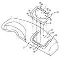
- FIG. 1is a perspective view of an airbag door system constructed according to the present invention and installed in an instrument panel;
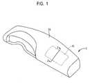
- FIG. 2is a cross-sectional view of the airbag door system of FIG. 1 taken along line 2 — 2 of FIG. 1;
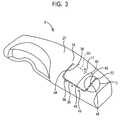
- FIG. 3is a perspective view of the substrate of the airbag door system of FIG. 1;
- FIG. 3Ais an alternative of the exploded view of the substrate and reinforcement member of the airbag door system of FIG. 1
- FIG. 4is an exploded view of the substrate and reinforcement member of the airbag door system of FIG. 1;
- FIG. 4Ais first variation of the perspective view of the substrate and reinforcement member of the airbag door system of FIG. 1;
- FIG. 4Bis a second variation of the perspective view of the substrate and reinforcement member of the airbag door system of FIG. 1;
- FIG. 5is a perspective view of the substrate and reinforcement member of the airbag door system of FIG. 1;
- FIG. 6is a first embodiment of an enlargement view taken from area C of FIG. 3;
- FIG. 7Ais the first embodiment of a cross-sectional view taken along line 7 — 7 of FIG. 6;
- FIG. 7Bis the second embodiment of a cross-sectional view taken along line 7 — 7 of FIG. 6;
- FIG. 7Cis the third embodiment of a cross-sectional view taken along line 7 — 7 of FIG. 6;
- FIG. 7Dis the fourth embodiment of a cross-sectional view taken along line 7 — 7 of FIG.6;
- FIG. 8is a second embodiment of an enlargement view taken along circle C of FIG.3;
- FIG. 9is a third embodiment of an enlargement view taken along circle C of FIG. 3;
- FIG. 10is a fourth embodiment of an enlargement view taken along circle C of FIG.3;
- FIG. 11is a cross-sectional enlargement view taken from FIG. 2;
- FIG. 12is a perspective view of the cross-sectional enlargement view of FIG. 11 .
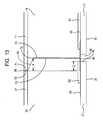
- FIG. 13is a cross-sectional enlargement view of a second embodiment.
- FIG. 14is a perspective view of the cross-sectional enlargement view of FIG. 13 .
- FIG. 15is a perspective view of a third embodiment.
- FIG. 16is a cross-sectional enlargement view of a fourth embodiment.
- FIG. 1illustrates an airbag door system 2 comprising a concealed airbag door 10 and an trim member 20 shown as an instrument panel.
- the airbag door 10is rectangular and comprises a single airbag door in a top mount position disposed within the confines of the trim member 20 .
- the shape, number of doors, and location of the airbag door 10is merely preferred and not considered limitive of the invention.
- the airbag door 10may be circular, oval, elliptical, rectangular, square, trapezoidal, trapezium, or any other geometric shape.
- the airbag door 10may comprise one, two, or more doors depending on whether the deployment pattern is that of a I, C, H, X, U or other configuration.
- the airbag door 10may be incorporated in a mid-mount, low-mount, or other position. Also, the airbag door 10 may be incorporated in trim members other than instrument panels such as side-trim panels (e.g. door trim panels, quarter trim panels), headliners, consoles (e.g. overhead, center floor mount), package shelves, pillars, and seats.
- side-trim panelse.g. door trim panels, quarter trim panels
- headlinerse.g. overhead, center floor mount
- consolese.g. overhead, center floor mount
- package shelvespillars, and seats.
- the general construction for the airbag door system 2comprises outer shell 4 , foam 6 , and substrate 8 .
- the outer shell 4 , foam 6 , and substrate 8are further separated in airbag door 10 and trim member 20 portions.
- the outer shell 4it is at least partially separated by partial shell sever 69 into outer shell 11 of airbag door 10 and outer shell 21 of trim member 20 .
- the foam 6it is at least partially separated by partial foam sever 72 into foam 14 of airbag door 10 and foam 24 of trim member 20 .
- substrateit is at least partially separated by substrate aperture 36 into airbag door substrate 17 and trim member substrate 27 .
- upper surfaces 12 , 22 of the outer shell 11 , 21are the surfaces viewed by a vehicle occupant.
- the lower surfaces 13 , 23 of the outer shell 11 , 21are adjacent the upper surfaces 15 , 25 of the foam 14 , 24 .
- lower surface 16 of the foam 14is generally adjacent the upper surface 31 of reinforcement member 30 while the lower surface 32 of reinforcement member 30 is adjacent the upper surface 18 of the substrate 17 .
- lower surface 26 of the foam 24is generally adjacent the upper surface 28 of the substrate 27 while the lower surface 29 of the substrate 27 is adjacent airbag canister housing 34 .
- both the airbag door substrate 17 and trim member substrate 27are preferably formed by injection molding.
- any suitable forming processmay be used. This includes, but is not limited to, all forms of injection molding (e.g. high pressure, low pressure injection molding, injection compression, stamping, coining, gas-assist), compression molding, reaction injection molding, blow molding, thermoforming, and vac-forming.
- the airbag door substrate 17 and trim member substrate 27are formed at a thickness in the range between and including 1.0 mm and 4.0 mm, and more preferably between and including 1.5 mm and 3.0 mm, and even more preferably 2.5 mm. Further, it should be understood that the thickness ranges identified above may be further subdivided into any 0.1 mm increment therebetween. Further, any suitable thickness outside the express ranges set forth above may also be used.
- the airbag door substrate 17 and trim member substrate 27are formed at the same time (i.e. during the same forming or injection molding cycle) and from the same material.
- the airbag door substrate 17may be formed separate from the trim member substrate 27 and subsequently joined thereto either during formation of the trim member substrate 27 or after formation of the trim member substrate 27 .
- the airbag door substrate 17may be formed prior to formation of the trim member substrate 27 and subsequently inserted into an injection mold for the trim member substrate 27 for joining thereto during formation of the trim member substrate 27 .
- Other processesmay also include those described in U.S. Pat. Nos.
- the airbag door substrate 17 and trim member substrate 27are formed using a polymer blend of polyphenylene oxide (PPO) and polystyrene (PS), and more preferably, General Electric's Noryl®.
- PPOpolyphenylene oxide
- PSpolystyrene
- any suitable materialmay be used. This includes, but is not limited to, materials containing carbonates (e.g. PC, PC/ABS); olefins (e.g. PP, PE, TPO), styrenes (e.g. PS, SMA, ABS), esters, urethanes (e.g. PU), vinyls, (e.g. PVC), and rubbers (e.g. NR, EPDM).
- the airbag door substrate 17 and trim member substrate 27are separated by one or more apertures 36 which define a line of mechanical weakness in the substrate 8 .
- a plurality of apertures 36exists and are arranged in a U-shaped pattern to create the preferred single, rectangular airbag door 10 discussed above.
- a single rectangular airbag door 10is merely preferred and not considered limitive of the invention.
- the apertures 36may be arranged in any pattern, including, but not limited to, that of the shape of a I, C, H, X, to facilitate the desired shape or number of airbag doors 10 .
- the plurality of apertures 36define three sides of the airbag door substrate 17 at 38 , 40 , and 42 . These three sides of the airbag door substrate 17 coincide with adjacent sides of the trim member substrate 27 at 44 , 46 , and 48 respectively.
- a junction 50defines a fourth side (located most forward in car position) between the airbag door substrate 17 and the trim member substrate 27 .
- apertures 36may also define at least a portion of the side defined by junction 50 .
- the apertures 36are preferably elongated such that their length L is of greater value than their corresponding width W. More preferably, the length L of the aperture is greater than or equal to four times the width W of the aperture (i.e. L ⁇ 4W). Even more preferably, the length L of the aperture is greater than or equal to eight times the width W of the aperture (i.e. L ⁇ 8W). Even more preferably, the length L of the aperture is greater than or equal to sixteen times the width W of the aperture (i.e. L>16W). Also as shown in FIG. 6, more preferably the apertures 36 are rectangular. More preferably, the length L of the rectangular aperture is 48.0 mm and the width W of the rectangular aperture is 3.0 mm. However, it is recognized that the apertures 36 may have a length L less equal to or of lesser value than their corresponding width W, for example as where the aperture is a square or a circle.
- apertures 36are preferably formed perpendicular to the upper surfaces 18 , 28 and lower surfaces 19 , 29 of substrates 17 , 27 .
- apertures 36may be also formed at an angle other than perpendicular to any or all of the adjacent surfaces 18 , 28 , 19 , 29 of the aperture 36 . In certain instances, such may be required to accommodate the angle of die draw during molding of the substrate 8 .
- the angleis preferably measured with respect to the substrate adjacent aperture 36 .
- FIG. 16shows apertures 36 , foam sever 72 and skin sever 69 still to be parallel to one another as the corresponding items in FIG. 2, it is recognized that any one of the three lines of mechanical weakness may exist at an angle different, and thus not parallel, to one another.
- the aperture or plurality of apertures 36terminate at each end thereof in tear stops 52 and 54 .
- the tear stops 52 and 54are round. More preferably, the diameter D of the tear stops 52 and 54 is greater than or equal to one times the width W of the aperture 36 (i.e. D ⁇ W). Even more preferably, the diameter D of the tear stops 52 and 54 is greater than or equal to one and one-half times the width W of the aperture 36 (i.e. D ⁇ 1.5W). Even more preferably, the diameter D of the tear stops 52 and 54 is greater than or equal to two times the width W of the aperture 36 (i.e. D ⁇ 2W). More preferably, the diameter D of the tear stops 52 and 54 is 6.0 mm and the width W of the aperture 36 is 3.0 mm.
- the apertures 36are separated by bridges 56 .
- Bridges 56preferably link the airbag door substrate 17 and trim member substrate 27 .
- the link between the airbag door substrate 17 and trim member substrate 27is desired to reduce, and preferably prevent, the airbag door 10 from inward movement, or sagging, relative to the trim member 20 prior to airbag deployment.
- the bridges 56preferably have a width F equal to at least the width W of aperture 36 .
- the width F of the bridges 56may actually be of greater value than that of the width W of the aperture 36 such as where the bridges overlay a portion of the airbag door substrate 17 and/or a portion of the trim member substrate 27 .
- the bridges 56are also integral portions with the airbag door substrate 17 and trim member substrate 27 . More preferably, the bridges 56 are formed as unitary (i.e. formed at the same time and same material) portions with the airbag door substrate 17 and trim member substrate 27 . More preferably, when bridges 56 are formed at the same time and same material as the airbag door substrate 17 and trim member substrate 27 , they are also connected to the airbag door substrate 17 and trim member substrate 27 . In this manner, bridges 56 can aid plastic flow between airbag door substrate 17 and trim member substrate 27 during substrate 17 , 27 molding.
- the link created between airbag door substrate 17 and trim member substrate 27 by bridges 56is broken during airbag deployment allowing the airbag door substrate 17 to move independent of the trim member substrate 27 . More preferably, as in the situation where the bridges 56 are formed with and connected to the airbag door substrate 17 and the trim member substrate 27 , the bridges 56 themselves break upon airbag deployment.
- the bridges 56may be formed with a constant or varying cross-sectional thickness across their width F equal to or less than substrate thickness T.
- substrate thickness Twhere the substrate thickness is uniform the substrate thickness T is typically equal to the nominal substrate thickness.
- the substrate thickness Tis preferably measured in an area of the substrate adjacent bridge 56 .
- bridge 56is shown to have a constant cross-sectional thickness E across its width F equal to the substrate thickness T.
- bridge 56is shown to also have a constant cross-sectional thickness across its width F with a minimum cross sectional thickness E less than the substrate thickness T.
- bridge 56is shown to have a varying cross-sectional thickness across its width F with a minimum cross-sectional thickness E less than the substrate thickness T.
- FIG. 7 C and FIG. 7Dare differentiated by the fact that bridge 56 of FIG. 7C is symmetrical across its width F while bridge 56 of FIG. 7D is not symmetrical across its width F.
- the bridge 56 depicted in FIG. 7A having a constant cross-sectional thickness E across its width F equal to the substrate thickness Tis preferred to the variations of FIGS. 7B-7D due to its simpler profile complexity and easier moldability during forming of the substrates 17 , 27 .
- bridges 56are formed with minimum cross sectional thickness E across their width F less than substrate thickness T. While not preferred, it is recognized that the bridges 56 may be formed with a cross-sectional thickness E equal to or greater than 10% of substrate thickness T (i.e. E ⁇ 0.1T). Preferably, cross sectional thickness E is equal to or greater than 50% of substrate thickness T (i.e. E ⁇ 0.5T), and more preferably cross sectional thickness E is equal to or greater than 75% of substrate thickness T (i.e. E ⁇ 0.75T) to facilitate proper forming during molding.
- bridges 56also have a length K.
- length Kis no greater than 10.0 mm and more preferably no greater than 5.0 mm.
- Airbag deployment testinghas shown that where a length K of the bridges 56 is greater than 5.0 mm, upon airbag deployment the bridges 56 tend to break less uniformly.
- the bridges 56have a length K of 1.0 mm to 5.0 mm and more preferably a length K of 2.0 mm to 4.0 mm. Even more preferably, the bridges 56 have a length K of 3.0 mm.
- the apertures 136may transition into the bridges 156 in the form of a radii design resulting in bridges 156 with a U-shaped edge appearance across their width and oval apertures 136 therebetween.
- the apertures 236may transition into the bridges 256 in the form of an arrow tip design resulting in bridges 256 with a V-shaped edge appearance across their width and hexagonal apertures 236 therebetween.
- the apertures 336may transition into the bridges 356 in the form of a trapezoidal design resulting in bridges 356 with an off-centered V-shaped edge appearance across their width and trapezoidal apertures 336 therebetween.
- the third and fourth embodimentsare preferred to the second embodiment given the apertures terminate in a point upon which to concentrate the deployment force.
- the bridges 56may vary in cross-sectional thickness E, length K, and aperture length L from one bridge 56 to another bridge 56 as to effect airbag door opening during airbag deployment.
- the junction 50terminates along its length at tear stops 52 and 54 .
- the junction 50does not include apertures 36 similar to the remaining three sides, but rather maintains airbag door substrate 17 and trim member substrate 27 in continual connection along its length between tear stops 52 and 54 .
- the junction 50may be molded with a constant or varying cross-sectional thickness along its length equal to or less than substrate thickness T.
- junction 50is molded with a varying cross-sectional thickness A as created by notch 58 which is less than the substrate thickness T.
- junction 50in combination with the reinforcement member 30 (discussed in greater detail below) will effect the opening characteristics of the airbag door 10 .
- junction 50may function as a hinge, a tether, and/or an energy management device.
- the junction 50may remain connected, fracture, or break.
- the junction 50may bend, fracture or break under different deployment conditions, albeit more uniformly than when the cross-sectional thickness A of the junction 50 is equal to the substrate thickness.
- the apertures 36are closed. As shown in FIG. 4, the apertures 36 are closed preferably via a strip layer of masking tape 60 placed over the apertures 36 and also preferably over adjacent portions of the upper surface 18 of the airbag door substrate 17 and upper surface 28 of trim member substrate 27 .
- the tape 60seals the apertures 36 and prevents the foam 14 , subsequently joined to the upper surfaces 18 , 28 of substrates 17 , 27 and lower surfaces 13 , 23 of the outer shell 11 , 21 as discussed below, from penetrating through the apertures 36 to the lower surfaces 19 , 29 of the substrates 17 , 27 .
- masking tape 60any material capable of forming a seal may be used including, but not limited to polymer films, paper, and textiles.
- apertures 36may be initially formed as closed sections during forming or molding of the substrate 8 , and subsequently cut opened (e.g. with a router, laser, knife, etc.) after the foam process discussed below.
- the thickness of the material overlying the apertures 36may be formed with a cross-sectional thickness anywhere between substrate thickness T and 10% of substrate thickness T (i.e. E ⁇ 0.1T).
- the thicknessis on the order of 10% to 25% of the substrate thickness T to facilitate easy cutting of the substrate material and opening of the apertures while balancing against any added difficulty in molding.
- tape 60is preferred to the use of a cutter as substrate particulate generated as a result of the cutting operation may cling to the substrates 17 , 27 after the cutter's use and become fragments upon airbag deployment.
- the lower surfaces 32 , 64 of a reinforcement member 30are preferably placed on the upper surfaces 18 , 28 of the substrates 17 , 27 as shown in FIGS. 2 and 4. As shown in FIG. 5, portions of the reinforcement member 30 may overlap the masking tape 60 previously placed on the upper surfaces 18 , 28 of the airbag door and trim member substrates 17 , 27 .
- the polymer film 60 ais die cut from roll or sheet stock and provided with a pressure sensitive adhesive on both sides. Unlike tape 60 , rather than having a U-shape substantially similar to the pattern of apertures 36 , the polymer film 60 a is preferably die cut to the approximate overall dimension of the reinforcement member 30 , and then first bonded to upper surfaces 18 , 28 of substrates 17 , 27 . After application to substrates 17 , 27 , the lower surfaces 32 , 64 of reinforcement member 30 are subsequently bonded over the remaining exposed surface of the polymer film 60 a.
- a polymer film 60 a with double sided adhesiveis preferred to the use of tape 60 as the lower surfaces 32 , 64 of the reinforcement member 30 are better held in place against the upper surfaces 18 , 28 of substrates 17 , 27 while rivets 68 discussed below are attached and expanded.
- the adhesive bond between the lower surfaces 32 , 64 of reinforcement member 30 and upper surfaces 18 , 28 of substrates 17 , 27reduces, and preferably prevents, foam 14 , 24 as discussed below from penetrating therebetween.
- portions of the substrates 17 , 27 which may break and subsequently fragment during airbag deploymentmay be better held in place and retained from entry into the vehicle occupant compartment as a result of being bonded to the polymer film 60 a .
- an adhesive without the polymer filme.g. hot melt, spray
- an adhesive without the polymer filmmay also be applied between the lower surfaces 32 , 64 of the reinforcement member 30 and the upper surfaces 18 , 28 of substrates 17 , 27 to create the adhesive bond therebetween.
- Reinforcement member 30is preferably made of metal, and more preferably steel. Other materials include, but are not limited to, aluminum, magnesium and plastics. As shown in FIG. 4, reinforcement member 30 includes an airbag door portion 61 and a trim member portion 62 . The lower surface 32 of the airbag door portion 61 of reinforcement member 30 is adjacent the upper surface 18 of airbag door substrate 17 . The lower surface 64 of the trim member portion 62 of reinforcement member 30 is adjacent upper surface 28 of trim member substrate 27 . The airbag door portion 61 and trim member portion 62 of the reinforcement member 30 may include items such as ribbing or bosses for added stiffness.
- the airbag door portion 61 and trim member portion 62 of reinforcement member 30are completely separated on three sides by a generally U-shaped aperture 63 which defines a line of mechanical weakness in the reinforcement member 30 .
- aperture 63will be at least partially overlying aperture 36 of substrate 8 as to permit a device, such as a knife, to extend through both aperture 36 of substrate 8 and aperture 63 of reinforcement member 30 and sever foam 6 as discussed below.
- the remaining side defining airbag door portion 61 and trim member portion 62 of reinforcement member 30(located most forward in car position) preferably contains a plurality of apertures 67 separating airbag door portions 61 and trim member portion 62 .
- aperture 63may also define at least a portion of this side of the reinforcement member 30 .
- Bridges 65 existing between the apertures 67 of the reinforcement member 30are not designed to break upon airbag deployment, but rather function as a hinge, a tether, and/or an energy management device when the airbag deployment force is applied to the airbag door 10 .
- the rivets 68may pierce completely through airbag door portion 61 of reinforcement member 30 , or may be directed from the upper surface 31 of the reinforcement member 30 .
- the rivets 68are subsequently expanded to attach reinforcement member 30 to substrate 17 .
- the combination of reinforcement member 30 with substrates 17 , 27comprises reinforcement member/substrate subassembly 84 .
- the trim member portion 62 of reinforcement member 30comprises a ring 86 as shown in FIG. 4 and more preferably a closed ring.
- the reinforcement member 30preferably contains six bolts 66 welded thereto and protruding from the lower surface 64 thereof.
- the six bolts 66are welded in a pattern in which three of the bolts 66 are spaced along the side of the reinforcement member 30 most forward in car position, while the remaining three bolts 66 are spaced along the side of the reinforcement member 30 most rearward in car position.
- additional bolts 66may be located on either or both of the two remaining sides of the ring 86 of reinforcement member 30 , or the existing bolts 66 may be merely moved to the two remaining sides leaving the sides of the reinforcement member most forward and rearward in car position without bolts 66 .
- All six bolts 66coincide with holes 49 formed in the trim member substrate 27 , and extend through the substrate 27 upon attachment of airbag door portion 61 of reinforcement member 30 to airbag door substrate 17 as discussed above.
- the bolts 66are used to attached the airbag canister housing 34 discussed below.
- ring 86overlies trim member substrate 27 along sides 44 , 46 , and 48 to the edge of apertures 36 . More preferably, the whole ring 86 substantially, and preferably completely, overlies trim member substrate 27 along sides 44 , 46 , and 48 to the edge of apertures 36 . In this manner, sides 44 , 46 , and 48 of trim member substrate 27 , which may break and subsequently fragment during airbag deployment, may be better held in place and retained by ring 86 from entry into the vehicle occupant compartment.
- the outer shell 4is preferably formed via slush molding at a thickness of 1.0 mm.
- the slush molding operationinvolves casting the shell material in a dry powder or bead form against a heated nickel electro-formed mold in a manner known in the art. Typical processes may include those described in U.S. Pat. Nos. 4,623,503; 5,445,510; 5,654,102; and 5,824,738 assigned to the assignee of the present invention, and incorporated herein by reference.
- the shell materialpreferably comprises a polyvinyl chloride (PVC) material, though any suitable material may be used. These material include, but are not limited to plastics (e.g. polyurethanes, polyolefins, and polyesters), leather, and textiles.
- the outer shell 6may be formed by vacuum forming, thermoforming, spraying, blow molding, injection molding.
- the outer shell 6is removed from the nickel electro-formed mold.
- a portion of the shell's thicknessis then severed from the shell's lower surface extending towards the upper surface to define a line of mechanical weakness in the shell 4 .
- the shell sever 69 and apertures 36at least partially overlie (as shown in FIG. 11 they completely overlie) one another for at least a portion of their lengths (as shown in FIG. 12 for their complete lengths) defining the airbag door 10 and trim member 20 .
- a second embodimentsuch as shown in FIG.
- shell sever 69 and apertures 36are off-set from one another for at least a portion of their lengths defining the airbag door 10 and trim member 20 .
- shell sever 69 and apertures 36are off-set from one another for their complete lengths defining the airbag door 10 and trim member 20 .
- the depth of the shell sever 69preferably ranges from 0.2 mm to 0.8 mm (i.e. 20% to 80% of the shell's thickness), in which case the unsevered thickness of the shell ranges from 0.8 mm to 0.2 mm (i.e 80% to 20% of the shell's thickness). More preferably, with a shell thickness of 1.0 mm, the depth of the sever 69 preferably ranges from 0.4 mm to 0.5 mm (i.e. 40% to 50% of the shell's thickness), in which case the unsevered thickness of the shell ranges from 0.6 mm to 0.5 mm (i.e. 60% to 50% of the shells's thickness).
- the depth of the shell sever 69may be preferred to exist between 20% to 80% of the shell's thickness, it is recognized that the depth of the shell sever 69 may range anywhere between 5% and 95% of the shell's thickness depending on the thickness and material used.
- the outer shell thicknessis typically equal to the nominal outer shell thickness.
- the outer shell thicknessis preferably measured in an area of the outer shell adjacent shell sever 69 .
- the line of mechanical weakness in the shell 6 as a result of shell severis preferably continuous, but may also be discontinuous such as represented by a plurality of holes, either through holes or blind holes, such as those disclosed in U.S. Pat. Nos. 5,632,914 and 5,961,143 assigned to the assignee of the present invention, and incorporated herein by reference.
- the line of mechanical weaknessneed not necessarily be achieved with a reduced cross-sectional thickness in comparison to the wall thickness, and as such other processes for creating the line of mechanical weakness may be employed such as those disclosed in U.S. Pat. Nos.
- the shell sever 69is preferably formed perpendicular to the lower surfaces 13 , 23 of outer shell 11 , 21 .
- shell sever 69may be formed at an angle other than perpendicular to either or both of the surfaces 13 , 23 .
- the angleis preferably measured with respect to the outer shell adjacent shell sever 69 .
- Shell sever 69is preferably created using a severing device such a cutting die, or more preferably, a knife mounted to the arm of a computer controlled robot.
- the knifemay be heated above ambient temperature and/or use ultrasonic frequency.
- the knife bladeis thin enough, about 0.5 mm, to make shell sever 69 extremely narrow.
- shell sever 69is sufficiently narrow such that surfaces 70 and 71 created as a result of the shell sever 69 will make contact with one another after shell sever 69 is created.
- surfaces 70 and 71may be sufficiently separated by shell sever 69 such that they will not make contact with one another after shell sever 69 is created.
- the unsevered thickness of the shellis to be controlled as opposed to the depth of the sever. Consequently, the sever may actually vary in depth over the course of its length where the thickness of the shell varies.
- shell sever 69is sufficiently narrow such that surfaces 70 and 71 created as a result of the shell sever 69 will make contact with one another after shell sever 69 is created.
- Surfaces 70 and 71 of shell sever 69preferably make contact with one another after shell sever 69 is created such that foam 6 applied directly adjacent to the shell sever 69 does not completely fill shell sever 69 , and more preferably does not enter or fill any portion of shell sever 69 , as a result of the foam forming process.
- foam 6may also be reduced from entering the shell sever 69 such by the use of a separate sealing device other than the outer shell 4 itself, such as applying tape to lower surfaces 13 , 23 of outer shell 11 , 21 and spanning the sever 69 prior to the foam forming process.
- a separate sealing deviceother than the outer shell 4 itself, such as applying tape to lower surfaces 13 , 23 of outer shell 11 , 21 and spanning the sever 69 prior to the foam forming process.
- the inventionuses only the outer shell 4 itself as a sealing device to reduce, and preferably eliminate, foam 6 from enter shell sever 69 .
- the moldreceives both the shell layer and member/substrate subassembly 84 .
- the lower surface of the shell layer 13 , 23 and upper surfaces 18 , 28 , 31 , and 89 of the reinforcement member/substrate subassembly 84are held from one another in fixed, spaced relation.
- a reactable urethane foam precursoris then poured or injected into the space between the shell and member/substrate subassembly and the mold closed.
- the thickness of the foamis 4.0 mm to 15.0 mm, and more preferably 8.0 mm to 12.0 mm.
- the foam sever 72 and shell sever 69at least partially overlie (as shown in FIG. 11 they completely overlie) one another for at least a portion of either lengths (as shown in FIG. 12 for their complete lengths) defining the airbag door 10 and trim member 20 .
- foam sever 72 and shell sever 69are off-set from one another for at least a portion of their lengths defining the airbag door 10 and trim member 20 .
- foam sever 72 and shell sever 69are off-set from one another for their complete lengths defining the airbag door 10 and trim member 20 .
- the third embodimenthas been found to reduce foam fragmentation upon deployment relative to the first embodiment and thus preferable.
- foam tearproceeds in a substantially parallel fashion to foam sever 72 .
- foam tearproceeds at an angle other than substantially parallel to foam sever 72 .
- foam sever 72 and apertures 36preferably at least partially overlie (as shown in FIG. 11 they completely overlie) one another for at least a portion of either lengths (as shown in FIG. 12 for their complete lengths) defining the airbag door 10 and trim member 20 . While not shown, it is recognized that foam sever 72 and apertures 36 may be off-set from one another for at least a portion of their lengths or their complete lengths defining the airbag door 10 and trim member 20 .
- foam sever 72 and apertures 36preferably overlie one another for at least a portion of their lengths defining the airbag door 10 and trim member 20
- foam sever 72 and shell sever 69are preferably off-set from one another for at least a portion of their lengths defining the airbag door 10 and trim member 20
- the shell sever 69 and foam sever 72are off-set from one another such that resulting outer shell 11 of airbag door 10 overhangs or is larger than the surface area of foam 14 of airbag door 10 prior to deployment.
- the distance of the off-setis measured laterally between where the respective lines of mechanical weakness begin relative to one another. If the value is greater than zero, an off-set exists and its magnitude is the lateral distance as measured. For example, in FIG. 13, relative to foam sever 72 and shell sever 69 , foam sever 72 begins at surface 73 and shell ever 69 begins at surface 71 . The lateral distance X measured between surfaces 73 and 71 is the off-set distance between shell sever 69 and foam sever 72 . For a second example, in FIG.
- aperturebegins at surface 46 and shell sever 69 begins at surface 71 .
- the lateral distance Z measured between surface 46 and 71is the off-set distance between apertures 36 and shell sever 69 .
- the lateral distance X′ measured between the beginning of surfaces 73 and 71is the off-set distance between shell sever 69 and foam sever 72 .
- the lateral distance Z′ measured between the beginning of surfaces 46 and 71is the off-set distance between apertures 36 and shell sever 69 .
- the foam sever 72 and shell sever 69are laterally off-set by an amount suitable to preferably achieve both a horizontal and vertical severing vector of the tear pathway created in the foam, such tear pathway propagating towards the line of mechanical weakness in the outer skin.
- the tear pathway 90 above the foam severhas both an upward vector component and a horizontal vector component in its tearing profile, i.e., the tear pathway moves upward and horizontally at the same time.
- this offsetis equal to or greater than 1.0 mm, more preferably, by amounts equal to or greater than, e.g., 1.1 mm, 1.2 mm, etc., up to an amount of 50 mm in 0.1 mm increments.
- offset valuesare preferably between 1.0 mm to 50.0 mm, at any 0.1 mm increment therebetween. Most preferably, offset values are preferably between the range of about 5.0 mm to 15.0 mm. A most preferred offset value is 10.0 mm.
- shell severis outboard of the foam sever.
- the foam sever 72does not extend to the lower surface of the shell layer, but rather leaves a 0.5 mm to 3.5 mm thick unsevered section of foam between the end of the foam sever 72 and lower surface of the shell.
- This unsevered section of foamhelps to prevent “read through” of the airbag door by a vehicle occupant prior to deployment.
- a foam thickness of 15.0 mm and a sever depth of 14.5 mmresults in a sever of 96.7% of the foam's thickness, in which case the unsevered thickness is 3.3% of the foam's thickness.
- a foam thickness of 4.0 mm and a sever depth of 0.5 mmresults in a sever of 12.5% of the foam's thickness, in which case the unsevered thickness is 87.5% of the foam's thickness.
- the foam's thicknessmay be completely severed.
- the unsevered thickness of the foam 6ranges between 1.0 mm and 3.0 mm, and more preferably is 2.0 mm.
- the severed depthpreferably ranges between 62.5% to 91.7% of the foam's thickness, and more preferably ranges between 75% and 83.3% of the foam's thickness.
- the foam thicknessis uniform the foam thickness is typically equal to the nominal foam thickness.
- the foam thicknessis preferably measured in an area of the foam adjacent foam sever 72 .
- the foam 6is preferably severed by a knife extending through apertures 36 and masking tape 60 from the lower surfaces 19 , 29 of the substrates 17 , 27 .
- the foam sever 72is preferably a discontinuous plurality of slots, as the foam beneath bridges 56 remains unsevered.
- the foam sever 72may be continuous as in the case in which one aperture 36 is used and bridges 65 do not exist.
- the foam sever 72is preferably formed perpendicular to the lower surfaces 16 , 26 of foam 14 , 24 .
- foam sever 69may be formed at an angle other than perpendicular to either or both of the surfaces 16 , 26 .
- the angleis preferably measured with respect to the foam adjacent foam sever 72 .
- foam sever 72is preferably created using a knife mounted to the arm of a computer controlled robot.
- the knifemay be heated above ambient temperature and/or use ultrasonic frequency.
- the knifeis thin enough, about 0.5 mm, to make foam sever 72 extremely narrow.
- foam sever 72is sufficiently narrow such that surfaces 73 and 74 created as a result of the foam sever 72 will make contact with one another after foam sever 72 is created. The resultant contact between surfaces 73 and 74 after foam sever 72 is created helps to reduce “read through” of the airbag door by a vehicle occupant prior to deployment.
- surfaces 73 and 74may be sufficiently separated by foam sever 72 such that they will not make contact with one another after foam sever 72 is created.
- the unsevered thickness of the foamis to be controlled as opposed to the depth of the sever. Consequently, the sever may actually vary in depth over the course of its length where the thickness of the foam varies.
- an airbag canister housing 34is preferably placed on the lower surface 29 of trim member substrate 27 .
- airbag canister housing 34preferably contains six holes 78 which coincides with the six bolts 66 welded to the reinforcement member 30 and protruding through the six holes 49 in the trim member substrate 27 .
- the six bolts 66 welded to the reinforcement member 30preferably extend through holes 49 in the trim member substrate 27 and then through holes 78 in the airbag canister housing 34 .
- the airbag canister housing 34is joined to the member/substrate subassembly 84 by the use of six nuts 80 which attach to the six bolts 66 of the reinforcement member 30 .
- the airbag canister housing 34substantially, and preferably completely, underlies trim member substrate 27 along sides 44 , 46 , and 48 to the edge of apertures 36 .
- sides 44 , 46 , and 48 of trim member substrate 27which may break and subsequently fragment during airbag deployment, may be sandwiched between the ring 86 the reinforcement member 30 and the airbag canister housing 34 and retained from entry into the vehicle occupant compartment.
- an adhesive 88may be located between the upper surface 76 of the airbag canister housing 34 and the lower surface 29 of the trim member substrate 27 to create an adhesive bond therebetween.
- the adhesive 88may be used alone or, preferably, in combination with mechanical fasteners such as bolts 66 and nuts 80 .
- the adhesive 88is particularly useful between the upper surface 76 of the airbag canister housing 34 and the lower surface 29 of the trim member substrate 27 adjacent junction 50 .
- adhesive 88also promotes a more uniform operation of junction 50 .
- junction 50tends to bend, fracture or break more uniformly when adhesive 88 is used adjacent thereto between the upper surface 76 of the airbag canister housing 34 and the lower surface 29 of the trim member substrate 27 rather than in its absence.
- portions of the trim member substrate 27 which may break and subsequently fragment during airbag deploymentmay be better held in place and retained from entry into the vehicle occupant compartment as a result of being bonded to the adhesive 88 .
Landscapes
- Engineering & Computer Science (AREA)
- Mechanical Engineering (AREA)
- Chemical & Material Sciences (AREA)
- Combustion & Propulsion (AREA)
- Transportation (AREA)
- Air Bags (AREA)
- Laminated Bodies (AREA)
Abstract
Description
Claims (24)
Priority Applications (13)
| Application Number | Priority Date | Filing Date | Title |
|---|---|---|---|
| US09/504,398US6402189B1 (en) | 2000-02-15 | 2000-02-15 | Airbag door and method for making same |
| ES01910669TES2269352T3 (en) | 2000-02-15 | 2001-02-14 | AIRBAG DOOR FOR VEHICLE THAT HAS THREE LAYERS WITH THREE RESPECTIVE LINES OF PARTIAL MECHANICAL WEAKNESS. |
| CA002400326ACA2400326A1 (en) | 2000-02-15 | 2001-02-14 | Vehicle airbag door having three layers with three respective partial mechanical weakness lines |
| EP01910669AEP1255664B8 (en) | 2000-02-15 | 2001-02-14 | Vehicle airbag door having three layers with three respective partial mechanical weakness lines |
| MXPA02007912AMXPA02007912A (en) | 2000-02-15 | 2001-02-14 | Vehicle airbag door having three layers with three respective partial mechanical weakness lines. |
| PCT/US2001/004728WO2001060664A1 (en) | 2000-02-15 | 2001-02-14 | Vehicle airbag door having three layers with three respective partial mechanical weakness lines |
| KR1020027010720AKR100734634B1 (en) | 2000-02-15 | 2001-02-14 | Automotive airbag door with three layers, each with three partially mechanical weak wires |
| AT01910669TATE334026T1 (en) | 2000-02-15 | 2001-02-14 | VEHICLE AIRBAG OPENING WITH THREE LAYERS AND EACH ONE MECHANICAL BREAKING POINT |
| JP2001559734AJP2003522675A (en) | 2000-02-15 | 2001-02-14 | A three-layer automotive air back door with three lines partially weakened |
| AU2001238254AAU2001238254A1 (en) | 2000-02-15 | 2001-02-14 | Vehicle airbag door having three layers with three respective partial mechanicalweakness lines |
| DE60121730TDE60121730T2 (en) | 2000-02-15 | 2001-02-14 | VEHICLE AIRBAG OPENING WITH THREE LAYERS AND EACH A MECHANICAL BREAKAGE POINT |
| US10/095,339US6709007B2 (en) | 2000-02-15 | 2002-03-07 | Airbag door and method for making same |
| US10/805,999US6976701B2 (en) | 2000-02-15 | 2004-03-22 | Airbag door and method for making same |
Applications Claiming Priority (1)
| Application Number | Priority Date | Filing Date | Title |
|---|---|---|---|
| US09/504,398US6402189B1 (en) | 2000-02-15 | 2000-02-15 | Airbag door and method for making same |
Related Child Applications (1)
| Application Number | Title | Priority Date | Filing Date |
|---|---|---|---|
| US10/095,339Continuation-In-PartUS6709007B2 (en) | 2000-02-15 | 2002-03-07 | Airbag door and method for making same |
Publications (1)
| Publication Number | Publication Date |
|---|---|
| US6402189B1true US6402189B1 (en) | 2002-06-11 |
Family
ID=24006100
Family Applications (1)
| Application Number | Title | Priority Date | Filing Date |
|---|---|---|---|
| US09/504,398Expired - LifetimeUS6402189B1 (en) | 2000-02-15 | 2000-02-15 | Airbag door and method for making same |
Country Status (11)
| Country | Link |
|---|---|
| US (1) | US6402189B1 (en) |
| EP (1) | EP1255664B8 (en) |
| JP (1) | JP2003522675A (en) |
| KR (1) | KR100734634B1 (en) |
| AT (1) | ATE334026T1 (en) |
| AU (1) | AU2001238254A1 (en) |
| CA (1) | CA2400326A1 (en) |
| DE (1) | DE60121730T2 (en) |
| ES (1) | ES2269352T3 (en) |
| MX (1) | MXPA02007912A (en) |
| WO (1) | WO2001060664A1 (en) |
Cited By (50)
| Publication number | Priority date | Publication date | Assignee | Title |
|---|---|---|---|---|
| US20020121768A1 (en)* | 2001-03-02 | 2002-09-05 | Calsonic Kansei Corporation | Vehicular air bag device |
| US6453535B1 (en)* | 1998-06-25 | 2002-09-24 | Tip Engineering Group, Inc. | Process for manufacturing an automotive trim piece preweakened to form an air bag deployment opening |
| US20020153710A1 (en)* | 2000-02-15 | 2002-10-24 | Gray John D. | Airbag door and method for making same |
| US6533314B2 (en)* | 1999-12-30 | 2003-03-18 | Delphi Technologies, Inc. | Instrument panel with integral hidden door cover and method of manufacture thereof |
| US6682091B1 (en)* | 1999-04-08 | 2004-01-27 | Magna Eybl Gmbh | Cover for an airbag module |
| US20040056454A1 (en)* | 2002-09-19 | 2004-03-25 | Trw Vehicle Safety Systems Inc. | Tear seam for air bag module |
| US20040061262A1 (en)* | 2002-09-30 | 2004-04-01 | Glenn Cowelchuk | Instrument panel skin for covering airbag and method of making same |
| US20040129367A1 (en)* | 2002-11-29 | 2004-07-08 | Peguform Gmbh & Co. Kg, | Method of producing weakened zones in shaped plastic parts by means of ultra sound cutting |
| EP1431134A3 (en)* | 2002-12-10 | 2004-07-28 | Calsonic Kansei Corporation | Door of Airbag apparatus for vehicle |
| WO2004067334A1 (en)* | 2003-01-29 | 2004-08-12 | Faurecia Innenraum Systeme Gmbh | Interior trimming piece |
| US20040262892A1 (en)* | 2003-06-30 | 2004-12-30 | Takata Corporation | Airbag module and cover |
| US20050087963A1 (en)* | 2003-10-24 | 2005-04-28 | Visteon Global Technologies, Inc. | Instrument panel having modular airbag door assembly |
| US20050167953A1 (en)* | 2004-01-30 | 2005-08-04 | Ulrich Weissert | Stiffening frame for an integral tether and tearstop in an air bag door |
| US20050167954A1 (en)* | 2004-01-30 | 2005-08-04 | Gray John D. | Stiffening frame for an integral tether and tearstop in an air bag door |
| US20050183897A1 (en)* | 2004-02-24 | 2005-08-25 | Lear Corporation | Two-shot co-injected automotive interior trim assembly and method |
| US20060022440A1 (en)* | 2004-07-29 | 2006-02-02 | Junichi Umehara | Airbag module |
| US20060066088A1 (en)* | 2004-09-30 | 2006-03-30 | Hier Michael J | Inflatable airbag cushion formed with a blown elastomer core and methods of using and manufacturing same |
| US20060082173A1 (en)* | 2004-10-19 | 2006-04-20 | Cowelchuk Glenn A | Automotive trim part with applique and method of making same |
| US20060082190A1 (en)* | 2004-10-19 | 2006-04-20 | Cowelchuk Glenn A | Automotive armrest with soft feel and method of making the same |
| US20060082109A1 (en)* | 2004-10-20 | 2006-04-20 | Hier Michael J | Method of making an automotive trim assembly having an integrated airbag door |
| US20060082106A1 (en)* | 2004-10-20 | 2006-04-20 | Hier Michael J | Automotive trim assembly having an integrated airbag door |
| US20060082179A1 (en)* | 2004-10-19 | 2006-04-20 | Depue Todd L | Automotive trim assembly having impact countermeasures and method of making the same |
| US20060097544A1 (en)* | 2004-11-09 | 2006-05-11 | Cowelchuk Glenn A | Automotive interior trim assembly and method |
| US20060097545A1 (en)* | 2004-11-09 | 2006-05-11 | Cowelchuk Glenn A | Vehicle door trim bolster with multi-feel cover and method of making the same |
| US20060097536A1 (en)* | 2004-11-10 | 2006-05-11 | Depue Todd L | Automotive compartment having an integrated spring mechanism and method of making the same |
| US20060188669A1 (en)* | 2005-02-15 | 2006-08-24 | Lisa Draxlmaier Gmbh | Interior trim part for interiors of motor vehicles |
| US7100941B2 (en) | 2003-02-24 | 2006-09-05 | Collins & Aikman | Pre-weakening of fabric covered airbag doors |
| US20060197322A1 (en)* | 2005-03-04 | 2006-09-07 | Lisa Draxlmaier Gmbh | Vehicle door trim and method for the manufacture thereof |
| US20060208468A1 (en)* | 2005-03-04 | 2006-09-21 | Lisa Draxlmaier Gmbh | Motor vehicle door trim and method for the manufacture thereof |
| EP1705076A1 (en)* | 2005-03-23 | 2006-09-27 | Lisa Dräxlmaier GmbH | Trim panel for a vehicle with weakened portions and method of manufacture the same |
| WO2006111212A1 (en)* | 2005-04-20 | 2006-10-26 | Eissmann Automotive Deutschland Gmbh | Cover for an airbag and method for the production thereof |
| US20060290110A1 (en)* | 2005-06-10 | 2006-12-28 | Lear Corporation | Interior panel part for motor vehicles and a method of manufacturing such an interior panel part |
| US20070013172A1 (en)* | 2005-07-14 | 2007-01-18 | Lear Corporation | A trim panel and a method of manufacture |
| US20070018435A1 (en)* | 2005-07-22 | 2007-01-25 | Lisa Draxlmaier Gmbh | Invisible airbag cover having a tear line |
| US20070205585A1 (en)* | 2006-03-03 | 2007-09-06 | Toyoda Gosei Co., Ltd. | Airbag cover |
| US20080018081A1 (en)* | 2006-07-24 | 2008-01-24 | Hyundai Mobis Co., Ltd. | Air bag module for vehicles |
| US20080128943A1 (en)* | 2006-12-01 | 2008-06-05 | Hager Richard A | Method for Manufacturing a Multi-Shot Molded Component |
| US7478854B2 (en) | 2004-10-19 | 2009-01-20 | International Automotive Components Group North America, Inc. | Automotive handle with soft feel and method of making the same |
| US20090096254A1 (en)* | 2007-10-11 | 2009-04-16 | Toyota Motor Engineering & Manufacturing North America, Inc. | Vehicle Headliner And Method Of Manufacture |
| US20090136735A1 (en)* | 2006-05-10 | 2009-05-28 | Peguform Gmbh | Method and device for producing a moulded part with an opening groove and moulded part |
| US20090232993A1 (en)* | 2005-02-15 | 2009-09-17 | Lisa Draxlmaier Gmbh | Methods and compositions for coating interior components of motor vehicles and interior components of motor vehicles coated using same |
| US20090243264A1 (en)* | 2004-08-05 | 2009-10-01 | Nicole Kaulbersch | Cover for an airbag and method for the production thereof |
| US20100251950A1 (en)* | 2009-04-02 | 2010-10-07 | Gm Global Technology Operations, Inc. | Sewing Method For Seat Cover |
| US20110210534A1 (en)* | 2009-06-19 | 2011-09-01 | Takata-Petri Ag | Air bag module for a vehicle occupant restraint system |
| US8246075B2 (en) | 2009-06-19 | 2012-08-21 | Takata AG | Airbag module for a vehicle occupant restraint system |
| US9022418B2 (en)* | 2012-12-27 | 2015-05-05 | Faurecia Interieur Industrie | Interior trim component for motor vehicle, adapted for covering an airbag |
| US20160137154A1 (en)* | 2014-11-18 | 2016-05-19 | International Automotive Components Group Gmbh | Interior trim part and method for its manufacture |
| US10144384B2 (en)* | 2016-03-29 | 2018-12-04 | Nihon Plast Co., Ltd. | Cover for airbag device |
| US20190225182A1 (en)* | 2018-01-24 | 2019-07-25 | Hyundai Mobis Co., Ltd. | Passenger air bag door |
| CN114734947A (en)* | 2022-04-07 | 2022-07-12 | 拓普电动车热管理系统(宁波)有限公司 | Air bag blasting weakening structure |
Families Citing this family (4)
| Publication number | Priority date | Publication date | Assignee | Title |
|---|---|---|---|---|
| US6721801B2 (en) | 2000-12-26 | 2004-04-13 | Brooks Automation | Increased network availability for computers using redundancy |
| JP4659382B2 (en) | 2004-04-01 | 2011-03-30 | タカタ株式会社 | Manufacturing method of airbag cover |
| JP4826879B2 (en)* | 2005-03-07 | 2011-11-30 | タカタ株式会社 | Mold for molding airbag cover, molding method, and airbag cover |
| JP4820473B2 (en)* | 2005-06-21 | 2011-11-24 | 日本プラスト株式会社 | Automotive interior panels |
Citations (55)
| Publication number | Priority date | Publication date | Assignee | Title |
|---|---|---|---|---|
| US4120516A (en) | 1975-12-05 | 1978-10-17 | Nissan Motor Company, Limited | Cover member for a safety air-cushion device and a method of producing the same |
| US4148503A (en)* | 1976-03-26 | 1979-04-10 | Toyota Jidosha Kogyo Kabushiki Kaisha | Inflating type occupant restraint device |
| US4246213A (en) | 1978-08-02 | 1981-01-20 | Nissan Motor Company, Limited | Method of producing a cover member for a safety air-cushion |
| US4903986A (en) | 1988-11-14 | 1990-02-27 | General Motors Corporation | Modular occupant restraint system |
| JPH0299324A (en) | 1988-10-07 | 1990-04-11 | Toyota Motor Corp | Preparation of interior part having air bag lid part |
| US4989895A (en) | 1990-04-19 | 1991-02-05 | General Motors Corporation | Occupant restraint system |
| US5013064A (en) | 1990-05-29 | 1991-05-07 | General Motors Corporation | Occupant restraint system |
| EP0428935A2 (en) | 1989-11-06 | 1991-05-29 | Tip Engineering Group, Inc. | Arrangement for providing an air bag deployment opening |
| US5060971A (en) | 1989-02-20 | 1991-10-29 | Takata Corporation | Vehicle air bag cover |
| GB2244243A (en) | 1990-05-24 | 1991-11-27 | Takata Corp | Cover for vehicle air bag |
| DE4115913A1 (en) | 1990-05-24 | 1991-11-28 | Takata Corp | COVER FOR RECEIVING A AIR BAG |
| US5072967A (en) | 1990-07-12 | 1991-12-17 | Davidson Textron Inc. | Instrument panel with invisible airbag deployment door |
| US5080393A (en)* | 1989-01-30 | 1992-01-14 | Tip Engineering Group, Inc. | Method and apparatus for forming an air bag deployment opening |
| US5096220A (en) | 1989-12-14 | 1992-03-17 | Takata Corporation | Cover for air bag system |
| US5110647A (en) | 1988-12-26 | 1992-05-05 | Takata Corporation | Cover for a vehicle air bag |
| US5131678A (en)* | 1990-12-03 | 1992-07-21 | Davidson Textron Inc. | Invisible air bag cover door |
| US5152548A (en) | 1990-05-24 | 1992-10-06 | Takata Corporation | Cover for accommodating an air bag |
| US5154444A (en) | 1991-04-05 | 1992-10-13 | Davidson Textron Inc. | Air bag retainer with cutting flaps |
| US5172931A (en) | 1990-10-26 | 1992-12-22 | Takata Corporation | Modular cover for an air bag |
| US5174602A (en) | 1990-05-24 | 1992-12-29 | Takata Corporation | Cover for accommodating an air bag |
| US5195773A (en) | 1990-05-24 | 1993-03-23 | Takata Corporation | Cover for accommodating an air bag |
| DE4241728A1 (en) | 1991-12-11 | 1993-06-17 | Takata Corp | |
| US5222760A (en)* | 1990-12-07 | 1993-06-29 | Davidson Textron Inc. | Decorative panel with invisible tear seam |
| US5316335A (en) | 1992-12-14 | 1994-05-31 | Davidson Textron Inc. | Self piercing cover assembly air bag |
| US5316822A (en) | 1991-07-23 | 1994-05-31 | Nihon Plast Co., Ltd. | Cover for vehicular air bag |
| US5346249A (en) | 1992-08-07 | 1994-09-13 | Morton International, Inc. | Airbag cover hinge reinforcement for high performance inflator |
| US5372379A (en)* | 1994-02-15 | 1994-12-13 | Davidson Textron Inc. | Preheated safety air bag cover |
| US5375874A (en) | 1992-05-21 | 1994-12-27 | Takata Corporation | Air bag device for passenger's seat |
| US5378014A (en)* | 1992-11-13 | 1995-01-03 | Davidson Textron Inc. | Dual door arrangement for air bag deployment |
| US5390950A (en)* | 1993-03-04 | 1995-02-21 | Tip Eng Group Inc | Method and arrangement for forming an air bag deployment opening in an auto interior trim piece |
| US5393088A (en) | 1993-10-05 | 1995-02-28 | Tip Eng Group Inc | Invisible seam deployment door installation with stabilized air bag deployment opening construction |
| US5437470A (en) | 1993-04-02 | 1995-08-01 | Nissan Motor Co., Ltd. | Air bag lid structure including a main lid and a sub lid |
| US5447328A (en)* | 1994-05-31 | 1995-09-05 | Davidson Textron | Trim panel having integral door cover |
| US5447327A (en) | 1994-05-25 | 1995-09-05 | Morton International, Inc. | Arrangement for providing an air bag deployment opening |
| US5456490A (en) | 1992-08-13 | 1995-10-10 | Davidson Textron Inc. | Hidden door for an air bag restraint system |
| US5484561A (en) | 1992-06-11 | 1996-01-16 | General Motors Corporation | Method of making a unitary inflatable restraint container |
| US5487558A (en)* | 1993-09-29 | 1996-01-30 | Mercedes-Benz Ag | Instrument panel in a motor vehicle |
| US5536037A (en)* | 1994-11-18 | 1996-07-16 | Trw Vehicle Safety Systems Inc. | Deployment door for use in a vehicle occupant restraint apparatus |
| US5544912A (en)* | 1994-12-19 | 1996-08-13 | General Motors Corporation | Supplemental inflation restraint and door arrangement |
| US5564733A (en) | 1994-10-24 | 1996-10-15 | Mercedes-Benz Ag | Instrument panel having an integrated, swing-open air-bag cover |
| US5590903A (en)* | 1995-09-29 | 1997-01-07 | Trw Vehicle Safety Systems, Inc. | Deployment door assembly |
| US5626357A (en)* | 1994-11-17 | 1997-05-06 | Morton International, Inc. | Passenger airbag module using an essentially unitary cover |
| US5641177A (en)* | 1994-05-25 | 1997-06-24 | Deutsche Fibrit Gesellschaft Ebers & Dr. Muller Mbh | Internal cladding member |
| EP0819584A2 (en) | 1996-07-19 | 1998-01-21 | Kabushiki Kaisha Inoac Corporation | Structure of air bag door of instrument panel |
| EP0846068A1 (en) | 1995-07-14 | 1998-06-10 | Peguform-Werke Gmbh | Plastics covering for vehicle with airbags and method and device for producing said covering |
| US5772240A (en) | 1994-03-10 | 1998-06-30 | Autoliv Development Ab | Air-bag arrangement |
| US5775727A (en)* | 1996-01-17 | 1998-07-07 | Trw Vehicle Safety Systems Inc. | Deployment door assembly |
| US5797619A (en) | 1989-01-30 | 1998-08-25 | Tip Engineering Group, Inc. | Automotive trim piece and method to form an air bag opening |
| US5810388A (en) | 1997-01-16 | 1998-09-22 | Ford Motor Company | Instrument panel air bag door and method of making thereof |
| DE19819573A1 (en) | 1997-05-02 | 1998-11-12 | Kansei Kk | Dashboard for vehicle |
| US5863064A (en) | 1997-08-14 | 1999-01-26 | Textron Autmotive Company Inc. | Skin for automotive air bag cover panel formed by casting different plastic materials |
| DE19800815C1 (en) | 1998-01-05 | 1999-02-04 | Sommer Allibert Lignotock Gmbh | Method of incorporating a hidden tear seam into a concealing foil backed with foam for an airbag guide channel in a motor vehicle interior |
| US5961143A (en) | 1998-05-11 | 1999-10-05 | Textron Automotive Company | Motor vehicle air bag cover having a skin with perforated score line and a method for manufacture thereof |
| US6065771A (en)* | 1997-02-19 | 2000-05-23 | Toyo Tire & Rubber Co., Ltd. | Instrument panel for air bag |
| US6070901A (en) | 1998-10-19 | 2000-06-06 | Ford Global Technologies, Inc. | Automotive instrument panel having an integral airbag |
Family Cites Families (2)
| Publication number | Priority date | Publication date | Assignee | Title |
|---|---|---|---|---|
| JP4011186B2 (en)* | 1998-03-03 | 2007-11-21 | 株式会社イノアックコーポレーション | Instrument panel with airbag door |
| JP4230008B2 (en)* | 1998-05-21 | 2009-02-25 | 株式会社イノアックコーポレーション | Method for manufacturing vehicle interior part having airbag door |
- 2000
- 2000-02-15USUS09/504,398patent/US6402189B1/ennot_activeExpired - Lifetime
- 2001
- 2001-02-14DEDE60121730Tpatent/DE60121730T2/ennot_activeExpired - Fee Related
- 2001-02-14ATAT01910669Tpatent/ATE334026T1/ennot_activeIP Right Cessation
- 2001-02-14ESES01910669Tpatent/ES2269352T3/ennot_activeExpired - Lifetime
- 2001-02-14KRKR1020027010720Apatent/KR100734634B1/ennot_activeExpired - Fee Related
- 2001-02-14WOPCT/US2001/004728patent/WO2001060664A1/enactiveIP Right Grant
- 2001-02-14AUAU2001238254Apatent/AU2001238254A1/ennot_activeAbandoned
- 2001-02-14JPJP2001559734Apatent/JP2003522675A/ennot_activeCeased
- 2001-02-14CACA002400326Apatent/CA2400326A1/ennot_activeAbandoned
- 2001-02-14EPEP01910669Apatent/EP1255664B8/ennot_activeExpired - Lifetime
- 2001-02-14MXMXPA02007912Apatent/MXPA02007912A/enactiveIP Right Grant
Patent Citations (61)
| Publication number | Priority date | Publication date | Assignee | Title |
|---|---|---|---|---|
| US4120516A (en) | 1975-12-05 | 1978-10-17 | Nissan Motor Company, Limited | Cover member for a safety air-cushion device and a method of producing the same |
| US4148503A (en)* | 1976-03-26 | 1979-04-10 | Toyota Jidosha Kogyo Kabushiki Kaisha | Inflating type occupant restraint device |
| US4246213A (en) | 1978-08-02 | 1981-01-20 | Nissan Motor Company, Limited | Method of producing a cover member for a safety air-cushion |
| JPH0299324A (en) | 1988-10-07 | 1990-04-11 | Toyota Motor Corp | Preparation of interior part having air bag lid part |
| US4903986A (en) | 1988-11-14 | 1990-02-27 | General Motors Corporation | Modular occupant restraint system |
| US5110647A (en) | 1988-12-26 | 1992-05-05 | Takata Corporation | Cover for a vehicle air bag |
| US5080393A (en)* | 1989-01-30 | 1992-01-14 | Tip Engineering Group, Inc. | Method and apparatus for forming an air bag deployment opening |
| US5797619A (en) | 1989-01-30 | 1998-08-25 | Tip Engineering Group, Inc. | Automotive trim piece and method to form an air bag opening |
| US5060971A (en) | 1989-02-20 | 1991-10-29 | Takata Corporation | Vehicle air bag cover |
| EP0428935A2 (en) | 1989-11-06 | 1991-05-29 | Tip Engineering Group, Inc. | Arrangement for providing an air bag deployment opening |
| US5082310A (en)* | 1989-11-06 | 1992-01-21 | Tip Engineering Group, Inc. | Arrangement for providing an air bag deployment opening |
| US5096220A (en) | 1989-12-14 | 1992-03-17 | Takata Corporation | Cover for air bag system |
| US4989895A (en) | 1990-04-19 | 1991-02-05 | General Motors Corporation | Occupant restraint system |
| US5195773A (en) | 1990-05-24 | 1993-03-23 | Takata Corporation | Cover for accommodating an air bag |
| DE4115913A1 (en) | 1990-05-24 | 1991-11-28 | Takata Corp | COVER FOR RECEIVING A AIR BAG |
| GB2244243A (en) | 1990-05-24 | 1991-11-27 | Takata Corp | Cover for vehicle air bag |
| US5143401A (en) | 1990-05-24 | 1992-09-01 | Takata Corporation | Cover for accommodating an air bag |
| US5152548A (en) | 1990-05-24 | 1992-10-06 | Takata Corporation | Cover for accommodating an air bag |
| US5172932A (en) | 1990-05-24 | 1992-12-22 | Takata Corporation | Air bag device |
| US5174602A (en) | 1990-05-24 | 1992-12-29 | Takata Corporation | Cover for accommodating an air bag |
| US5013064A (en) | 1990-05-29 | 1991-05-07 | General Motors Corporation | Occupant restraint system |
| US5072967A (en) | 1990-07-12 | 1991-12-17 | Davidson Textron Inc. | Instrument panel with invisible airbag deployment door |
| US5172931A (en) | 1990-10-26 | 1992-12-22 | Takata Corporation | Modular cover for an air bag |
| US5131678A (en)* | 1990-12-03 | 1992-07-21 | Davidson Textron Inc. | Invisible air bag cover door |
| US5222760A (en)* | 1990-12-07 | 1993-06-29 | Davidson Textron Inc. | Decorative panel with invisible tear seam |
| US5154444A (en) | 1991-04-05 | 1992-10-13 | Davidson Textron Inc. | Air bag retainer with cutting flaps |
| US5316822A (en) | 1991-07-23 | 1994-05-31 | Nihon Plast Co., Ltd. | Cover for vehicular air bag |
| DE4241728A1 (en) | 1991-12-11 | 1993-06-17 | Takata Corp | |
| US5292150A (en) | 1991-12-11 | 1994-03-08 | Takata Corporation | Cover of air bag device |
| US5375874A (en) | 1992-05-21 | 1994-12-27 | Takata Corporation | Air bag device for passenger's seat |
| US5484561A (en) | 1992-06-11 | 1996-01-16 | General Motors Corporation | Method of making a unitary inflatable restraint container |
| US5346249A (en) | 1992-08-07 | 1994-09-13 | Morton International, Inc. | Airbag cover hinge reinforcement for high performance inflator |
| US5456490A (en) | 1992-08-13 | 1995-10-10 | Davidson Textron Inc. | Hidden door for an air bag restraint system |
| US5378014A (en)* | 1992-11-13 | 1995-01-03 | Davidson Textron Inc. | Dual door arrangement for air bag deployment |
| US5316335A (en) | 1992-12-14 | 1994-05-31 | Davidson Textron Inc. | Self piercing cover assembly air bag |
| US5390950A (en)* | 1993-03-04 | 1995-02-21 | Tip Eng Group Inc | Method and arrangement for forming an air bag deployment opening in an auto interior trim piece |
| US5437470A (en) | 1993-04-02 | 1995-08-01 | Nissan Motor Co., Ltd. | Air bag lid structure including a main lid and a sub lid |
| US5487558A (en)* | 1993-09-29 | 1996-01-30 | Mercedes-Benz Ag | Instrument panel in a motor vehicle |
| US5393088A (en) | 1993-10-05 | 1995-02-28 | Tip Eng Group Inc | Invisible seam deployment door installation with stabilized air bag deployment opening construction |
| US5372379A (en)* | 1994-02-15 | 1994-12-13 | Davidson Textron Inc. | Preheated safety air bag cover |
| US5772240A (en) | 1994-03-10 | 1998-06-30 | Autoliv Development Ab | Air-bag arrangement |
| US5641177A (en)* | 1994-05-25 | 1997-06-24 | Deutsche Fibrit Gesellschaft Ebers & Dr. Muller Mbh | Internal cladding member |
| US5447327A (en) | 1994-05-25 | 1995-09-05 | Morton International, Inc. | Arrangement for providing an air bag deployment opening |
| US5447328A (en)* | 1994-05-31 | 1995-09-05 | Davidson Textron | Trim panel having integral door cover |
| US5564733A (en) | 1994-10-24 | 1996-10-15 | Mercedes-Benz Ag | Instrument panel having an integrated, swing-open air-bag cover |
| US5626357A (en)* | 1994-11-17 | 1997-05-06 | Morton International, Inc. | Passenger airbag module using an essentially unitary cover |
| US5536037A (en)* | 1994-11-18 | 1996-07-16 | Trw Vehicle Safety Systems Inc. | Deployment door for use in a vehicle occupant restraint apparatus |
| US5544912A (en)* | 1994-12-19 | 1996-08-13 | General Motors Corporation | Supplemental inflation restraint and door arrangement |
| EP0846068B1 (en) | 1995-07-14 | 1999-09-29 | Peguform Gmbh | Plastics covering for vehicle with airbags and method and device for producing said covering |
| EP0846068A1 (en) | 1995-07-14 | 1998-06-10 | Peguform-Werke Gmbh | Plastics covering for vehicle with airbags and method and device for producing said covering |
| US5590903A (en)* | 1995-09-29 | 1997-01-07 | Trw Vehicle Safety Systems, Inc. | Deployment door assembly |
| US5775727A (en)* | 1996-01-17 | 1998-07-07 | Trw Vehicle Safety Systems Inc. | Deployment door assembly |
| US5863062A (en)* | 1996-07-19 | 1999-01-26 | Kabushiki Kaisha Inoac Corporation | Structure of air bag door of instrument panel |
| EP0819584A2 (en) | 1996-07-19 | 1998-01-21 | Kabushiki Kaisha Inoac Corporation | Structure of air bag door of instrument panel |
| US5810388A (en) | 1997-01-16 | 1998-09-22 | Ford Motor Company | Instrument panel air bag door and method of making thereof |
| US6065771A (en)* | 1997-02-19 | 2000-05-23 | Toyo Tire & Rubber Co., Ltd. | Instrument panel for air bag |
| DE19819573A1 (en) | 1997-05-02 | 1998-11-12 | Kansei Kk | Dashboard for vehicle |
| US5863064A (en) | 1997-08-14 | 1999-01-26 | Textron Autmotive Company Inc. | Skin for automotive air bag cover panel formed by casting different plastic materials |
| DE19800815C1 (en) | 1998-01-05 | 1999-02-04 | Sommer Allibert Lignotock Gmbh | Method of incorporating a hidden tear seam into a concealing foil backed with foam for an airbag guide channel in a motor vehicle interior |
| US5961143A (en) | 1998-05-11 | 1999-10-05 | Textron Automotive Company | Motor vehicle air bag cover having a skin with perforated score line and a method for manufacture thereof |
| US6070901A (en) | 1998-10-19 | 2000-06-06 | Ford Global Technologies, Inc. | Automotive instrument panel having an integral airbag |
Cited By (82)
| Publication number | Priority date | Publication date | Assignee | Title |
|---|---|---|---|---|
| US6453535B1 (en)* | 1998-06-25 | 2002-09-24 | Tip Engineering Group, Inc. | Process for manufacturing an automotive trim piece preweakened to form an air bag deployment opening |
| US6682091B1 (en)* | 1999-04-08 | 2004-01-27 | Magna Eybl Gmbh | Cover for an airbag module |
| US6533314B2 (en)* | 1999-12-30 | 2003-03-18 | Delphi Technologies, Inc. | Instrument panel with integral hidden door cover and method of manufacture thereof |
| US20040183280A1 (en)* | 2000-02-15 | 2004-09-23 | Gray John D. | Airbag door and method for making same |
| US20020153710A1 (en)* | 2000-02-15 | 2002-10-24 | Gray John D. | Airbag door and method for making same |
| US6709007B2 (en)* | 2000-02-15 | 2004-03-23 | Collins & Aikman Automotive Company Inc. | Airbag door and method for making same |
| US6976701B2 (en) | 2000-02-15 | 2005-12-20 | Collins & Aikman Automotive Company Inc. | Airbag door and method for making same |
| US20020121768A1 (en)* | 2001-03-02 | 2002-09-05 | Calsonic Kansei Corporation | Vehicular air bag device |
| US6846006B2 (en)* | 2001-03-02 | 2005-01-25 | Calsonic Kansei Corporation | Vehicular air bag device |
| WO2003076230A3 (en)* | 2002-03-07 | 2004-03-18 | Collins & Aikman Automotive Co | Airbag door and method of making same |
| US7029025B2 (en)* | 2002-09-19 | 2006-04-18 | Trw Vehicle Safety Systems Inc. | Tear seam for air bag module |
| US20040056454A1 (en)* | 2002-09-19 | 2004-03-25 | Trw Vehicle Safety Systems Inc. | Tear seam for air bag module |
| US20040061262A1 (en)* | 2002-09-30 | 2004-04-01 | Glenn Cowelchuk | Instrument panel skin for covering airbag and method of making same |
| US20040129367A1 (en)* | 2002-11-29 | 2004-07-08 | Peguform Gmbh & Co. Kg, | Method of producing weakened zones in shaped plastic parts by means of ultra sound cutting |
| US6827799B2 (en) | 2002-11-29 | 2004-12-07 | Peguform Gmbh & Co. Kg | Method of producing weakened zones in shaped plastic parts by means of ultra sound cutting |
| US20040164524A1 (en)* | 2002-12-10 | 2004-08-26 | Calsonic Kansei Corporation | Airbag apparatus for vehicle |
| EP1431134A3 (en)* | 2002-12-10 | 2004-07-28 | Calsonic Kansei Corporation | Door of Airbag apparatus for vehicle |
| WO2004067334A1 (en)* | 2003-01-29 | 2004-08-12 | Faurecia Innenraum Systeme Gmbh | Interior trimming piece |
| US7841617B2 (en) | 2003-01-29 | 2010-11-30 | Faurecia Innenraum Systeme Gmbh | Interior trimming piece |
| US20060175808A1 (en)* | 2003-01-29 | 2006-08-10 | Albert Brandstatter | Interior trimming piece |
| US7556284B2 (en) | 2003-02-24 | 2009-07-07 | Riha Keith A | Pre-weakening of fabric covered airbag doors |
| US7100941B2 (en) | 2003-02-24 | 2006-09-05 | Collins & Aikman | Pre-weakening of fabric covered airbag doors |
| US20040262892A1 (en)* | 2003-06-30 | 2004-12-30 | Takata Corporation | Airbag module and cover |
| US20050087963A1 (en)* | 2003-10-24 | 2005-04-28 | Visteon Global Technologies, Inc. | Instrument panel having modular airbag door assembly |
| US7237797B2 (en) | 2003-10-24 | 2007-07-03 | Visteon Global Technologies, Inc. | Instrument panel having modular airbag door assembly |
| US7278654B2 (en) | 2004-01-30 | 2007-10-09 | Collins & Aikman Products Co. | Stiffening frame for an integral tether and tearstop in an air bag door |
| US7156415B2 (en) | 2004-01-30 | 2007-01-02 | Collins & Aikman Products Co. | Stiffening frame for an integral tether and tearstop in an air bag door |
| US20050167954A1 (en)* | 2004-01-30 | 2005-08-04 | Gray John D. | Stiffening frame for an integral tether and tearstop in an air bag door |
| US20050167953A1 (en)* | 2004-01-30 | 2005-08-04 | Ulrich Weissert | Stiffening frame for an integral tether and tearstop in an air bag door |
| US20050183897A1 (en)* | 2004-02-24 | 2005-08-25 | Lear Corporation | Two-shot co-injected automotive interior trim assembly and method |
| US20060022440A1 (en)* | 2004-07-29 | 2006-02-02 | Junichi Umehara | Airbag module |
| US20090243264A1 (en)* | 2004-08-05 | 2009-10-01 | Nicole Kaulbersch | Cover for an airbag and method for the production thereof |
| US20060066088A1 (en)* | 2004-09-30 | 2006-03-30 | Hier Michael J | Inflatable airbag cushion formed with a blown elastomer core and methods of using and manufacturing same |
| US7156437B2 (en) | 2004-10-19 | 2007-01-02 | Lear Corporation | Automotive trim part with applique and method of making same |
| US7478854B2 (en) | 2004-10-19 | 2009-01-20 | International Automotive Components Group North America, Inc. | Automotive handle with soft feel and method of making the same |
| US7458631B2 (en) | 2004-10-19 | 2008-12-02 | International Automotive Components Group North America, Inc. | Automotive armrest with soft feel and method of making the same |
| US20060082173A1 (en)* | 2004-10-19 | 2006-04-20 | Cowelchuk Glenn A | Automotive trim part with applique and method of making same |
| US20060082190A1 (en)* | 2004-10-19 | 2006-04-20 | Cowelchuk Glenn A | Automotive armrest with soft feel and method of making the same |
| US20070080474A1 (en)* | 2004-10-19 | 2007-04-12 | Lear Corporation | Method of Making An Automotive Trim Part With Applique |
| US20060082179A1 (en)* | 2004-10-19 | 2006-04-20 | Depue Todd L | Automotive trim assembly having impact countermeasures and method of making the same |
| US20060082109A1 (en)* | 2004-10-20 | 2006-04-20 | Hier Michael J | Method of making an automotive trim assembly having an integrated airbag door |
| US7458604B2 (en) | 2004-10-20 | 2008-12-02 | International Automotive Components Group North America, Inc. | Automotive trim assembly having an integrated airbag door |
| US20060082106A1 (en)* | 2004-10-20 | 2006-04-20 | Hier Michael J | Automotive trim assembly having an integrated airbag door |
| US20060097544A1 (en)* | 2004-11-09 | 2006-05-11 | Cowelchuk Glenn A | Automotive interior trim assembly and method |
| US20060097545A1 (en)* | 2004-11-09 | 2006-05-11 | Cowelchuk Glenn A | Vehicle door trim bolster with multi-feel cover and method of making the same |
| US20060097536A1 (en)* | 2004-11-10 | 2006-05-11 | Depue Todd L | Automotive compartment having an integrated spring mechanism and method of making the same |
| US7192074B2 (en) | 2004-11-10 | 2007-03-20 | Lear Corporation | Automotive compartment having an integrated spring mechanism and method of making the same |
| US20090232993A1 (en)* | 2005-02-15 | 2009-09-17 | Lisa Draxlmaier Gmbh | Methods and compositions for coating interior components of motor vehicles and interior components of motor vehicles coated using same |
| US8221843B2 (en) | 2005-02-15 | 2012-07-17 | Lisa Dräxlmaier GmbH | Methods and compositions for coating interior components of motor vehicles and interior components of motor vehicles coated using same |
| US20060188669A1 (en)* | 2005-02-15 | 2006-08-24 | Lisa Draxlmaier Gmbh | Interior trim part for interiors of motor vehicles |
| US7384063B2 (en) | 2005-03-04 | 2008-06-10 | Lisa Dräxlmaier GmbH | Motor vehicle door trim and method for the manufacture thereof |
| US20060208468A1 (en)* | 2005-03-04 | 2006-09-21 | Lisa Draxlmaier Gmbh | Motor vehicle door trim and method for the manufacture thereof |
| US20060197322A1 (en)* | 2005-03-04 | 2006-09-07 | Lisa Draxlmaier Gmbh | Vehicle door trim and method for the manufacture thereof |
| US7490851B2 (en) | 2005-03-04 | 2009-02-17 | Lisa Dräxlmeier GmbH | Vehicle door trim and method for the manufacture thereof |
| EP1705076A1 (en)* | 2005-03-23 | 2006-09-27 | Lisa Dräxlmaier GmbH | Trim panel for a vehicle with weakened portions and method of manufacture the same |
| US7625004B2 (en) | 2005-03-23 | 2009-12-01 | Lisa Draelmaier GmbH | Motor vehicle trim element having weakened areas and methods for the manufacture thereof |
| US20060220354A1 (en)* | 2005-03-23 | 2006-10-05 | Lisa Draxlmaier Gmbh | Motor vehicle trim element having weakened areas and methods for the manufacture thereof |
| WO2006111212A1 (en)* | 2005-04-20 | 2006-10-26 | Eissmann Automotive Deutschland Gmbh | Cover for an airbag and method for the production thereof |
| US20060290110A1 (en)* | 2005-06-10 | 2006-12-28 | Lear Corporation | Interior panel part for motor vehicles and a method of manufacturing such an interior panel part |
| US7384061B2 (en)* | 2005-07-14 | 2008-06-10 | International Automotive Components Group North America, Inc. | Trim panel and a method of manufacture |
| US20070013172A1 (en)* | 2005-07-14 | 2007-01-18 | Lear Corporation | A trim panel and a method of manufacture |
| US7810836B2 (en) | 2005-07-22 | 2010-10-12 | Lisa Draxlmaier Gmbh | Invisible airbag cover having a tear line |
| US20070018435A1 (en)* | 2005-07-22 | 2007-01-25 | Lisa Draxlmaier Gmbh | Invisible airbag cover having a tear line |
| US20070205585A1 (en)* | 2006-03-03 | 2007-09-06 | Toyoda Gosei Co., Ltd. | Airbag cover |
| US7607681B2 (en)* | 2006-03-03 | 2009-10-27 | Toyoda Gosei Co., Ltd. | Airbag cover |
| US20090136735A1 (en)* | 2006-05-10 | 2009-05-28 | Peguform Gmbh | Method and device for producing a moulded part with an opening groove and moulded part |
| US20080018081A1 (en)* | 2006-07-24 | 2008-01-24 | Hyundai Mobis Co., Ltd. | Air bag module for vehicles |
| US20080128943A1 (en)* | 2006-12-01 | 2008-06-05 | Hager Richard A | Method for Manufacturing a Multi-Shot Molded Component |
| US8012393B2 (en)* | 2006-12-01 | 2011-09-06 | Magna International of America | Method for manufacturing a multi-shot molded component |
| US7651143B2 (en) | 2007-10-11 | 2010-01-26 | Toyota Motor Engineering & Manufacturing North America, Inc. | Vehicle headliner and method of manufacture |
| US20090096254A1 (en)* | 2007-10-11 | 2009-04-16 | Toyota Motor Engineering & Manufacturing North America, Inc. | Vehicle Headliner And Method Of Manufacture |
| US20100251950A1 (en)* | 2009-04-02 | 2010-10-07 | Gm Global Technology Operations, Inc. | Sewing Method For Seat Cover |
| US8171868B2 (en)* | 2009-04-02 | 2012-05-08 | GM Global Technology Operations LLC | Sewing method for seat cover |
| US20110210534A1 (en)* | 2009-06-19 | 2011-09-01 | Takata-Petri Ag | Air bag module for a vehicle occupant restraint system |
| US8246075B2 (en) | 2009-06-19 | 2012-08-21 | Takata AG | Airbag module for a vehicle occupant restraint system |
| US8267422B2 (en) | 2009-06-19 | 2012-09-18 | Takata AG | Air bag module for a vehicle occupant restraint system |
| US9022418B2 (en)* | 2012-12-27 | 2015-05-05 | Faurecia Interieur Industrie | Interior trim component for motor vehicle, adapted for covering an airbag |
| US20160137154A1 (en)* | 2014-11-18 | 2016-05-19 | International Automotive Components Group Gmbh | Interior trim part and method for its manufacture |
| US10144384B2 (en)* | 2016-03-29 | 2018-12-04 | Nihon Plast Co., Ltd. | Cover for airbag device |
| US20190225182A1 (en)* | 2018-01-24 | 2019-07-25 | Hyundai Mobis Co., Ltd. | Passenger air bag door |
| US10933835B2 (en)* | 2018-01-24 | 2021-03-02 | Hyundai Mobis Co., Ltd. | Passenger air bag door |
| CN114734947A (en)* | 2022-04-07 | 2022-07-12 | 拓普电动车热管理系统(宁波)有限公司 | Air bag blasting weakening structure |
Also Published As
| Publication number | Publication date |
|---|---|
| CA2400326A1 (en) | 2001-08-23 |
| AU2001238254A1 (en) | 2001-08-27 |
| DE60121730D1 (en) | 2006-09-07 |
| DE60121730T2 (en) | 2007-08-02 |
| WO2001060664A1 (en) | 2001-08-23 |
| EP1255664B1 (en) | 2006-07-26 |
| EP1255664B8 (en) | 2006-12-20 |
| ATE334026T1 (en) | 2006-08-15 |
| EP1255664A1 (en) | 2002-11-13 |
| JP2003522675A (en) | 2003-07-29 |
| ES2269352T3 (en) | 2007-04-01 |
| KR20030001361A (en) | 2003-01-06 |
| KR100734634B1 (en) | 2007-07-02 |
| MXPA02007912A (en) | 2003-03-10 |
Similar Documents
| Publication | Publication Date | Title |
|---|---|---|
| US6402189B1 (en) | Airbag door and method for making same | |
| US6709007B2 (en) | Airbag door and method for making same | |
| US5779262A (en) | Car interior finish member with air bag cover | |
| US5979931A (en) | Air bag cover | |
| US6203056B1 (en) | Apparatus for deploying an airbag through a hard panel | |
| JP3009208B2 (en) | Closing member for airbag deployment opening and method for cutting its skin | |
| EP0928259B1 (en) | Frontal weakening of invisible air bag cover | |
| US6955376B1 (en) | Apparatus for deploying an air bag through a hard panel | |
| JP2009526708A (en) | Automotive structure with hidden airbag doors and integral airbag chute | |
| US20060079144A1 (en) | Plastic substrate and method for the production thereof | |
| US20070246918A1 (en) | Instrument panel with integral hidden door cover and method of manufacture thereof | |
| EP1393990B1 (en) | Air-bag-door-equipped vehicle interior trim article and method for fabricating the same | |
| US20080315566A1 (en) | Instrument panel with integral hidden door cover and method of manufacture thereof | |
| US6623030B2 (en) | Airbag door assembly for an instrument panel and method of making the airbag door assembly | |
| US7976057B2 (en) | Automotive milled PSIR scoring with interlaced interfaces | |
| JP4610998B2 (en) | Instrument panel with integrated airbag door | |
| JP4668459B2 (en) | Automotive airbag equipment | |
| KR100496690B1 (en) | reaction-plate hinge structure for inflating of passenger-air-bag | |
| KR100499946B1 (en) | door-plate and reaction-plate hinge structure for inflating of passenger-air-bag | |
| JPH0858512A (en) | Structure of air bag door part in cabin side member | |
| JP2000071914A (en) | Lid structure of on-vehicle air bag device | |
| JP2000071917A (en) | Air bag door structure for instrument panel | |
| JP2002225667A (en) | Air bag door-integrated instrument panel |
Legal Events
| Date | Code | Title | Description |
|---|---|---|---|
| AS | Assignment | Owner name:TEXTRON AUTOMOTIVE COMPANY, INC., MICHIGAN Free format text:ASSIGNMENT OF ASSIGNORS INTEREST;ASSIGNORS:GRAY, JOHN D.;BUNN, PHILIP A.;KORTE, BAS;AND OTHERS;REEL/FRAME:010904/0095;SIGNING DATES FROM 20000228 TO 20000330 | |
| AS | Assignment | Owner name:JPMORGAN CHASE BANK, AS COLLATERAL AGENT, TEXAS Free format text:SECURITY INTEREST;ASSIGNOR:COLLINS & AIKMAN DEVELOPMENT COMPANY (DE CORPORATION);REEL/FRAME:012676/0783 Effective date:20011220 | |
| STCF | Information on status: patent grant | Free format text:PATENTED CASE | |
| AS | Assignment | Owner name:COLLINS & ALKMAN PROUCTS CO., MICHIGAN Free format text:ASSIGNMENT OF ASSIGNORS INTEREST;ASSIGNOR:KAUTEX, INC. (F/K/A) TEXTRON AUTOMOTIVE COMPANY, INC.;REEL/FRAME:015312/0258 Effective date:20011220 | |
| FPAY | Fee payment | Year of fee payment:4 | |
| AS | Assignment | Owner name:COLLINS & AIKMAN PRODUCTS, LLC, MICHIGAN Free format text:CORPORATE CONVERSION;ASSIGNOR:COLLINS & AIKMAN PRODUCTS CO.;REEL/FRAME:021118/0945 Effective date:20071206 Owner name:COLLINS & AIKMAN PRODUCTS, LLC,MICHIGAN Free format text:CORPORATE CONVERSION;ASSIGNOR:COLLINS & AIKMAN PRODUCTS CO.;REEL/FRAME:021118/0945 Effective date:20071206 | |
| AS | Assignment | Owner name:FORD GLOBAL TECHNOLOGIES, LLC, MICHIGAN Free format text:ASSIGNMENT OF ASSIGNORS INTEREST;ASSIGNOR:COLLINS & AIKMAN PRODUCTS LLC;REEL/FRAME:021849/0495 Effective date:20080626 Owner name:FORD GLOBAL TECHNOLOGIES, LLC,MICHIGAN Free format text:ASSIGNMENT OF ASSIGNORS INTEREST;ASSIGNOR:COLLINS & AIKMAN PRODUCTS LLC;REEL/FRAME:021849/0495 Effective date:20080626 | |
| FEPP | Fee payment procedure | Free format text:PAYER NUMBER DE-ASSIGNED (ORIGINAL EVENT CODE: RMPN); ENTITY STATUS OF PATENT OWNER: LARGE ENTITY Free format text:PAYOR NUMBER ASSIGNED (ORIGINAL EVENT CODE: ASPN); ENTITY STATUS OF PATENT OWNER: LARGE ENTITY | |
| FPAY | Fee payment | Year of fee payment:8 | |
| FPAY | Fee payment | Year of fee payment:12 |