US6401644B2 - Stick control system for waterjet boats - Google Patents
Stick control system for waterjet boatsDownload PDFInfo
- Publication number
- US6401644B2 US6401644B2US09/809,784US80978401AUS6401644B2US 6401644 B2US6401644 B2US 6401644B2US 80978401 AUS80978401 AUS 80978401AUS 6401644 B2US6401644 B2US 6401644B2
- Authority
- US
- United States
- Prior art keywords
- boat
- nozzle
- water
- bucket
- thrust
- Prior art date
- Legal status (The legal status is an assumption and is not a legal conclusion. Google has not performed a legal analysis and makes no representation as to the accuracy of the status listed.)
- Expired - Lifetime
Links
Images


Classifications
- B—PERFORMING OPERATIONS; TRANSPORTING
- B63—SHIPS OR OTHER WATERBORNE VESSELS; RELATED EQUIPMENT
- B63H—MARINE PROPULSION OR STEERING
- B63H25/00—Steering; Slowing-down otherwise than by use of propulsive elements; Dynamic anchoring, i.e. positioning vessels by means of main or auxiliary propulsive elements
- B63H25/42—Steering or dynamic anchoring by propulsive elements; Steering or dynamic anchoring by propellers used therefor only; Steering or dynamic anchoring by rudders carrying propellers
- B—PERFORMING OPERATIONS; TRANSPORTING
- B63—SHIPS OR OTHER WATERBORNE VESSELS; RELATED EQUIPMENT
- B63H—MARINE PROPULSION OR STEERING
- B63H11/00—Marine propulsion by water jets
- B63H11/02—Marine propulsion by water jets the propulsive medium being ambient water
- B63H11/10—Marine propulsion by water jets the propulsive medium being ambient water having means for deflecting jet or influencing cross-section thereof
- B63H11/107—Direction control of propulsive fluid
- B63H11/11—Direction control of propulsive fluid with bucket or clamshell-type reversing means
- B—PERFORMING OPERATIONS; TRANSPORTING
- B63—SHIPS OR OTHER WATERBORNE VESSELS; RELATED EQUIPMENT
- B63H—MARINE PROPULSION OR STEERING
- B63H25/00—Steering; Slowing-down otherwise than by use of propulsive elements; Dynamic anchoring, i.e. positioning vessels by means of main or auxiliary propulsive elements
- B63H25/02—Initiating means for steering, for slowing down, otherwise than by use of propulsive elements, or for dynamic anchoring
Definitions
- the inventionrelates to steering and thrust control systems for waterjet driven boats.
- seawaterWith a waterjet drive, seawater is drawn in through the bottom of the boat and ejected in a stream out the back. The reaction to this movement of water is the propulsive force that moves the boat.
- a nozzleNear the back of the stream is a nozzle, which serves two functions. It accelerates the stream by reducing its diameter, and it can be turned from side to side to deflect the exiting stream to apply a component of side force on the aft part of the boat.
- the nozzleis to a jet what a rudder is to a boat equipped with conventional propellers. Both are typically connected to a steering wheel.
- the aftmost portion of the jet, just behind the nozzle,is a device called a reversing bucket. Its function is to allow the operator to reverse some or all of the stream in order to stop or back up the boat.
- the bucketIn normal underway operation the bucket is elevated above the stream and has no effect.
- the bucketWhen reduced forward thrust is desired the bucket can be lowered into the stream, forcing a portion of the flow through curved channels until it exits in a forward and slightly downward direction.
- the neutral bucket positionWhen roughly half the stream is still streaming aft below the bucket and half is being reversed to a more forward direction (the neutral bucket position), an approximate balance point can be reached that results in approximately no forward or aft thrust on the boat.
- a waterjetis either engaged and pumping water or disengaged and not pumping water. It does not ordinarily have a forward and reverse in the same manner as a conventional propeller.
- a transmission with reverse gearcan be provided as a means of allowing the engine to run without engaging the jet and to allow for backflushing that results from reversing the drive shaft to the jet to clear an obstruction that may have been drawn against the jet inlet. Actual reverse thrust is accomplished with the jet engaged in the forward direction and the bucket lowered, similar in concept to the reversing arrangement on aviation jet engines.
- Waterjet driveshave numerous advantages, e.g., low draft, reduced noise, improved high-speed maneuverability. But they can make a boat difficult to control at slow speeds in tight quarters (e.g., when docking). The reason for this is that, heretofore, there has been no simple way to achieve zero thrust or zero side force. In a conventionally powered boat, zero thrust and zero side force are easily achieved, simply by putting the transmission into neutral, thereby bringing the propeller to rest. But with a waterjet, the only way to achieve zero thrust is to move the bucket to a position at which the net of the forward and reverse portions of the jet is balanced. That position can only be chosen approximately. It takes considerable training and experience for an operator to acquire a sense of what the waterjet drive is doing, to allow successful slow speed operation.
- Waterjet drivesalso behave differently in reverse from propeller driven craft. Because the flow of water through the jet is always in one direction, deflection of the stream results in the same sideward force regardless of whether the boat is moving forward or in reverse. This is in contrast to a conventional rudder, whose effect on the stern of a boat is reversed depending on the direction of travel through the water. This difference in steering in reverse presents difficulties for new operators, who anticipate that steering direction will change when the boat is backing up.
- a thrusteris often installed in a tube that runs from side to side at the bow below the waterline. In the middle of this tube is a propeller that can thrust either way by reversing rotation. In smaller boats, this propeller is usually driven by an electric motor.
- the combination of waterjet and bowthrustercan give a boat extraordinary maneuverability. Movement in any direction in the plane of the water's surface is possible, even directly sideways. But, unfortunately, the operator is typically required to skillfully coordinate different controls simultaneously to take full advantage of this maneuverability.
- a foot pedal or left/right deflection of a hand-operated levermay be used to control the bowthruster, a steering wheel, to control the rear nozzle, and a throttle lever, to control speed.
- Some very large waterjet driven shipshave solved the zero thrust difficulty by controlling the waterjet with an inertial control system that senses applied thrust (e.g., using accelerometers), and adjusts the waterjet bucket position until a desired thrust level is achieved.
- applied thruste.g., using accelerometers
- the control systemadjusts the bucket position until the inertial sensors detect zero applied thrust. This solution is too expensive for small boats (i.e., boats 75 feet or less in length).
- the inventionhas numerous advantages. It allows a relatively unskilled operator of a jet boat to quickly master low-speed control of the boat.
- control of reversing bucket, nozzle, and bowthrusterare combined in a single joystick in a manner that is surprisingly easy for an unskilled operator to master.
- This control arrangementalso overcomes the problem that waterjet drives tend to behave differently in reverse than conventional propeller driven craft.
- the inventionfeatures providing a bucket position sensor connected to the reversing bucket of a waterjet drive, and controlling the bucket in response to an output of the position sensor to enable the bucket to be automatically moved to a neutral thrust position.
- a joystickmay be configured so that when the joystick is placed in its neutral-position the drive mechanism automatically moves the reversing bucket to the neutral thrust position.
- a centering forcecan be provided in the joystick so that when released by the operator, the joystick returns to its neutral position and the thrust is returned to neutral.
- the joystickcan be configured so that rotation (or twist) of the joystick about a generally vertical axis controls rotation of the waterjet nozzle about its axis.
- a nozzle position sensormay be connected to the nozzle, and provide control circuitry with a measurement of the position of the waterjet nozzle.
- the joystickmay have a centering torque that returns the stick to a zero rotation position when released by the operator.
- the control circuitrymay be configured with the nozzle position sensor so that releasing the joystick and allowing it to return to the zero rotation position automatically causes the nozzle to return to a zero sideward force position.
- the automatic zeroing of sideward forcecan be combined with the automatic zeroing of forward/reverse thrust, so that when the operator releases the joystick all propulsion forces on the boat are brought to zero.
- a bowthrustercan be controlled by left/right movement of the same joystick, so that leftward movement of the joystick produces a leftward movement of the bow of the boat and rightward movement of the joystick produces rightward movement of the bow.
- the bucket position sensor, joystick, and control circuitrymay be configured to provide at least two modes of operation, a first mode in which a follow-up relationship exists between forward/aft movement of the stick control member and up/down movement of the reversing bucket, and a second mode in which a non-follow-up relationship exists between forward/aft movement of the stick control member and up/down movement of the reversing bucket.
- the nozzle position sensor, joystick, and control circuitrymay be configured to provide a follow-up relationship between the rotation of the stick control member and rotation of the nozzle.
- the electrical circuitrymay be configured to provide both a docking mode and a power steer mode of operation, wherein in the docking mode of operation, the bucket position sensor, nozzle position sensor, and stick control member are configured so that both bucket position control and nozzle position control have a follow-up relationship to the respective movements of the stick control member, and wherein in the power steer mode of operation, the bucket position sensor, nozzle position sensor, and stick control member are configured so that bucket position control is non-follow-up and nozzle position control is follow-up.
- the electrical circuitry and stick control membermay be configured so that rotational movement of the stick member produces less rotation of the nozzle than in the docking mode.
- a trim adjustment controlmay be provided to permit the operator to adjust an offset between nozzle position and joystick rotation.
- Hydraulic cylindersmay be used to position the bucket and/or nozzle, and the components may be configured to provide two speeds of movement of the hydraulic cylinder, a high speed movement for use when the cylinder is more than a predetermined distance away from the position prescribed by the control circuitry, and a low speed movement for use when the cylinder is less than the predetermined distance.
- FIG. 1Ais an elevation view of a prior art boat equipped with a waterjet drive and bowthruster.
- FIG. 1Bis a plan view of the same prior art boat.
- FIGS. 2A, 2 B, and 2 Care enlarged, diagrammatic, elevation views of the waterjet and reversing bucket of FIG. 1A, showing the bucket in three different positions.
- FIGS. 3A-3Fare enlarged, diagrammatic, plan views of the waterjet and reversing bucket of FIG. 1B, showing the nozzle in three different positions for the case of the reversing bucket being all of the way up (maximum forward thrust; FIGS. 3A-3C) and all of the way down (maximum reverse thrust; FIGS. 3 D-F).
- FIG. 4is an overall electrical and hydraulic schematic of a preferred embodiment of the invention.
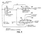
- FIG. 5is a schematic of the hydraulic valve assembly used to control the position of the reversing bucket of the preferred embodiment.
- FIGS. 1A and 1BA boat 10 with a waterjet drive 12 and bowthruster 16 is shown in FIGS. 1A and 1B. Water enters the drive through inlet 8 , and exits through nozzle 18 .
- FIGS. 2A-2Care enlarged views of the waterjet drive 12 , showing the reversing bucket 14 in full forward (FIG. 2 A), approximately neutral (FIG. 2 B), and full reverse (FIG. 2C) positions.
- FIGS. 3A-3Cshow the waterjet nozzle 18 in three different angular positions (the nozzle rotates about a generally vertical axis) for the case in which the reversing bucket is all of the way up: left sideways thrust (FIG. 3 A), approximately neutral thrust (FIG. 3 B), and right sideways thrust (FIG. 3 C).
- left sideways thrust(FIG. 3 A)
- approximately neutral thrust(FIG. 3 B)
- FIG. 3 Cright sideways thrust
- Nozzle thrustis predominantly directed rearwardly, but a sideward component of thrust is provided when the nozzle is angled to the left (FIG. 3A) or right (FIG. 3 C).
- FIGS. 3D-3Fshow the waterjet nozzle 18 in the same three angular positions for the case in which the reversing bucket is fully down.
- the buckethas the effect of reversing the dominant thrust direction, but the sideward component of thrust is approximately the same as if the bucket were all of the way up (e.g., the sideward component is approximately the same in FIGS. 3A and 3D, and in 3 C and 3 F).
- FIG. 4shows the principal electrical and hydraulic components of a preferred embodiment.
- the figureis organized in three sections.
- the upper portionrelates to control of the waterjet nozzle 18 ; the middle, to control of the reversing bucket 14 ; the lower, to control of the bowthruster 16 .
- Operator control of the nozzle, bucket, and bowthrusteris achieved using a joystick 20 and steering wheel 22 .
- the joystick 20has three independent directions of movement: rotating or twisting movement about a vertical axis, for control of the nozzle (upper section of FIG. 4 ); forward/aft movement, for control of the bucket (middle of FIG. 4 ); left/right (port/starboard) movement, for control of the bowthruster (bottom of FIG. 4 ).
- a centering forceor torque, in the case of rotation
- the centering forceis preferably provided by springs.
- a mode selection switchpanel 24is used by the operator to vary the relationship between movements of the joystick and movements of the nozzle and reversing bucket.
- the operatorcan select from among three modes: Helm, Docking, and Power Steer (using momentary, illuminated switches).
- Outputs from switchpanel 24are fed to switching circuit 26 , from which mode control outputs MS 1 , MS 2 , MS 3 are fed to various components of the system.
- Other outputs (not shown) of the switching circuitperform various conventional functions, e.g., controlling indicator lights on the switchpanel.
- a row of 10 double-bright LEDsis also provided (not shown) as a rough indicator of bucket position.
- a sustained pushbutton switchis used to dim both switch lighting and the row of LEDs.
- a small trim knobis used to offset the center position of the nozzle in the Power Steer mode (it is connected to a 270 degree potentiometer).
- the switching circuitis contained on a printed circuit board housed in an electronics enclosure. All other electrical components in the system connect to this board, including joystick, switchpanel 24 , power supply leads, bowthruster contactors 94 , 96 and autopilot output.
- a single sheathed cableleads aft from the electronics enclosure to hydraulic solenoid valves 88 , 90 in the hydraulic valve assembly, and bucket and nozzle position sensors 46 , 56 .
- the circuit boardsupplies a regulated voltage to position sensors and joystick.
- Itcontains a logic section of diodes and relays to switch between modes, a set of comparison circuits 54 , 76 to accomplish the follow-up action between joystick and the jet, adjustments for calibrating the follow-up circuit, power switching relays 50 , 52 , 70 , 72 , 74 to trigger the hydraulic solenoids 88 , 90 and nozzle pump motor 36 , electronic end stop circuits 48 , 64 for bucket and nozzle travel, and a circuit for dimming the switchpanel display.
- the hydraulic valve assemblyis designed to mount near the jet, although it could be mounted at any point that allows plumbing between the hydraulic pump and bucket positioning cylinder.
- the primary componentsare a priority flow controller 86 , solenoid cartridge valve 88 with one NO and one NC outlet, and a reversing solenoid valve 90 with spring return to tandem center. Also included on the plate is a junction box to connect solenoid valves, bucket and nozzle position sensors and autopilot/nozzle pump.
- the position sensorsare sealed 5 K ohm, 360 degree potentiometers. These are preferably mounted so that they are in the middle of their travel at neutral bucket and nozzle, as this allows calibration of neutral bucket and neutral nozzle positions by simply loosening the position sensor brackets and rotating the sensors.
- Helmis the default mode, which the system is in when power is first supplied to the switching circuit 26 .
- Helm modethe boat is steered solely by the steering wheel (in conjunction with the autopilot, if activated), and is the mode typically used underway when the boat operator prefers to steer with the wheel.
- Helm modealso serves as the failsafe mode in the event of a failure of the joystick or switching circuit.
- the steering wheelis connected hydraulically (in a conventional manner) to steering ram 30 , which drives tiller arm 32 , which, in turn, is mechanically coupled to the waterjet nozzle.
- control output MS 1is low (i.e., zero volts), and thus autopilot relay 34 remains unactivated, with the result that autopilot output signals are passed to the autopilot pump 36 , but inputs from the joystick and associated electronics are blocked.
- the reversing bucketfunctions in a non-follow-up manner, i.e., forward or aft movement of the joystick functions as a simple up/down directional switch for movement of the bucket.
- Forward movement of the joystickcauses the bucket to move upward as long as the joystick is held forward of center.
- aft movementcauses the bucket to move downwardly for as long as the joystick is held aft of center.
- the joystickis at rest, i.e., in the neutral center position, the bucket remains at its current orientation.
- tapping the joystick forward or aft momentarily in Helm modecauses the bucket to move incrementally upward or downward by a small amount and then remain in that position.
- Docking modeis the mode used for slow speed maneuvering, e.g., in approaching a dock or slip.
- both bucket and nozzleare controlled by the joystick in a follow-up manner.
- moving the joystick to a positioncauses the corresponding device (e.g., the bucket) to move to a corresponding position (e.g., halfway up).
- twisting of the joystickproduces rotation of the nozzle. Twisting the joystick produces an output signal 79 that is compared by comparison circuit 54 to the output of position sensor 56 , which measures the position of the nozzle.
- the comparison circuitproduces speed and direction signals 58 , 60 , which control motor drive circuit 62 , which, in turn, supplies a signal to autopilot pump 36 .
- the resultis that the nozzle moves until the output of position sensor 56 matches the joystick output signal. For example, if the joystick is twisted to the right from a neutral position, there is initially a large difference in voltage between the joystick output and the output of the tiller position signal. This produces a movement of the nozzle in a direction that causes the stern of the boat to move to port (left).
- the comparison circuit 54uses pulse width modulation to drive the autopilot pump.
- a continuous signalis delivered to the autopilot pump.
- the continuous signalis replaced with a pulsed signal, which has the effect of slowing down movement of the nozzle.
- Control output MS 1is high in Docking mode, so that the autopilot relay blocks the autopilot output signal, and instead drives the autopilot pump with the output of the motor drive circuit.
- An end stop circuit 64compares the output of position sensor 56 to a stored voltage corresponding to the ends of travel of the nozzle tiller arm 32 , and activates end stop relays 66 in the event that the tiller arm reaches one or the other ends of its allowed travel. Trim circuit 68 is not active in Docking mode (MS 2 is low).
- Bucket control in Docking modeis also done in a follow-up manner.
- Control output MS 3controls bucket mode relay 38 so that 12 VDC is supplied not to joystick switch 40 (as in the case of Helm mode) but to relays 70 , 72 , 74 , which control the outputs of comparison circuit 76 .
- the switch function of the joystickis replaced with a forward/aft potentiometer output 78 , which is compared to the output of position sensor to by comparison circuit 76 .
- the comparison circuitproduces three outputs, a bucket-up signal 80 , a bucket-down signal 82 , and a shift-to-high-speed signal 84 .
- Hydraulic valve assembly 42is capable of driving the bucket at two rates of speed, a high rate that is used when the bucket is far away from the position commanded by the joystick, and a low rate of speed when the bucket is near the desired position. This allows the bucket to be rapidly moved to a desired position, while also being brought to rest without the vibration and noise associated with stopping a fast moving hydraulic cylinder.
- the dual speed controlis achieved using the hydraulic components shown in FIG. 5 .
- a reversing solenoid valve 90governs the direction in which fluid is supplied to the cylinder.
- a bucket up signaldrives the valve in one direction
- a bucket down signaldrives the valve in the reverse direction.
- the rate of flow of hydraulic fluid through the solenoid valveis governed by a second valve 88 , working in conjunction with a flow regulator 86 .
- the regulatordivides the incoming supply flow into a controlled flow output CF and an excess flow output EF.
- the controlled flow output CFis always delivered to the reversing solenoid valve 90 , but when the shift-to-high-speed signal is supplied to valve 88 , the excess flow output is combined with the controlled flow output, to increase the rate of flow.
- Solenoid valve 88accomplishes this by moving from the position drawn in FIG. 5 (in which the excess flow output is returned to the reservoir) to a position in which the excess flow is connected to the controlled flow output. In that position, the excess flow EF is routed back to and summed with the controlled flow CF.
- the third mode of operationis the Power Steer mode, in which the boat operator steers underway using the joystick rather than the wheel.
- Bucket controlis the same as in Helm mode, i.e., non-follow-up (the joystick works as a up/down switch to control the reversing bucket).
- Nozzle controlis similar to Docking mode, except that a trim circuit 68 is activated by control output MS 2 .
- the trim circuitreduces the sensitivity of the joystick, so that the same degree of twist in Power Steer produces less nozzle movement than in Docking.
- a trim potentiometer (not shown) on the control panelis activated, allowing the operator to adjust the nozzle position that corresponds to zero twist of the joystick. This allows the operator to make small adjustments to the boat's track, e.g., to compensate for the effect of crosswind or current (without requiring that the operator maintain a slight twist on the joystick).
- the bowthruster 16operates the same in all modes, but is only normally useful in the slow speed maneuvering associated with the Docking mode.
- Left/right (port/starboard) movements of the joystickactivate switch 92 , which delivers 12 VDC to either the port contactor 94 or the starboard contactor 96 .
- When activated contactors 94 , 96connect high power to the bowthruster motor.
- Contactor 94delivers high power of one polarity
- contactor 96delivers high power in the opposite polarity. The result is that port deflection of the joystick produces bowthruster action causing movement of the bow to port, and starboard deflection, movement of the bow to starboard.
Landscapes
- Chemical & Material Sciences (AREA)
- Engineering & Computer Science (AREA)
- Combustion & Propulsion (AREA)
- Mechanical Engineering (AREA)
- Ocean & Marine Engineering (AREA)
- Mechanical Control Devices (AREA)
- Perforating, Stamping-Out Or Severing By Means Other Than Cutting (AREA)
- Toys (AREA)
Abstract
Description
Claims (17)
Priority Applications (1)
| Application Number | Priority Date | Filing Date | Title |
|---|---|---|---|
| US09/809,784US6401644B2 (en) | 1998-09-03 | 2001-03-16 | Stick control system for waterjet boats |
Applications Claiming Priority (2)
| Application Number | Priority Date | Filing Date | Title |
|---|---|---|---|
| US09/146,596US6234100B1 (en) | 1998-09-03 | 1998-09-03 | Stick control system for waterjet boats |
| US09/809,784US6401644B2 (en) | 1998-09-03 | 2001-03-16 | Stick control system for waterjet boats |
Related Parent Applications (1)
| Application Number | Title | Priority Date | Filing Date |
|---|---|---|---|
| US09/146,596ContinuationUS6234100B1 (en) | 1998-09-03 | 1998-09-03 | Stick control system for waterjet boats |
Publications (2)
| Publication Number | Publication Date |
|---|---|
| US20010021613A1 US20010021613A1 (en) | 2001-09-13 |
| US6401644B2true US6401644B2 (en) | 2002-06-11 |
Family
ID=22518106
Family Applications (5)
| Application Number | Title | Priority Date | Filing Date |
|---|---|---|---|
| US09/146,596Expired - LifetimeUS6234100B1 (en) | 1998-09-03 | 1998-09-03 | Stick control system for waterjet boats |
| US09/617,173Expired - LifetimeUS6447349B1 (en) | 1998-09-03 | 2000-07-17 | Stick control system for waterjet boats |
| US09/811,013Expired - LifetimeUS6453835B2 (en) | 1998-09-03 | 2001-03-16 | Steering and thrust control system for waterjet boats |
| US09/809,784Expired - LifetimeUS6401644B2 (en) | 1998-09-03 | 2001-03-16 | Stick control system for waterjet boats |
| US10/236,882AbandonedUS20030077954A1 (en) | 1998-09-03 | 2002-09-05 | Stick control system for waterjet boats |
Family Applications Before (3)
| Application Number | Title | Priority Date | Filing Date |
|---|---|---|---|
| US09/146,596Expired - LifetimeUS6234100B1 (en) | 1998-09-03 | 1998-09-03 | Stick control system for waterjet boats |
| US09/617,173Expired - LifetimeUS6447349B1 (en) | 1998-09-03 | 2000-07-17 | Stick control system for waterjet boats |
| US09/811,013Expired - LifetimeUS6453835B2 (en) | 1998-09-03 | 2001-03-16 | Steering and thrust control system for waterjet boats |
Family Applications After (1)
| Application Number | Title | Priority Date | Filing Date |
|---|---|---|---|
| US10/236,882AbandonedUS20030077954A1 (en) | 1998-09-03 | 2002-09-05 | Stick control system for waterjet boats |
Country Status (7)
| Country | Link |
|---|---|
| US (5) | US6234100B1 (en) |
| EP (1) | EP1107907B1 (en) |
| AT (1) | ATE274446T1 (en) |
| AU (1) | AU5809199A (en) |
| DE (1) | DE69919725T2 (en) |
| NZ (1) | NZ332407A (en) |
| WO (1) | WO2000013967A1 (en) |
Cited By (23)
| Publication number | Priority date | Publication date | Assignee | Title |
|---|---|---|---|---|
| US20030079668A1 (en)* | 2001-09-28 | 2003-05-01 | Vector Controls, Inc. | Method and apparatus for controlling a waterjet-driven marine vessel |
| US20050042948A1 (en)* | 2003-08-07 | 2005-02-24 | Bombardier Recreational Products Inc. | Engine cover with air intake system for watercraft |
| US20050042951A1 (en)* | 2001-09-28 | 2005-02-24 | Morvillo Robert A. | Method and apparatus for controlling a waterjet-driven marine vessel |
| US20050075016A1 (en)* | 2003-10-03 | 2005-04-07 | Azimut-Benetti S.P.A. | Control system for boats |
| US20060121803A1 (en)* | 2001-08-06 | 2006-06-08 | Morvillo Robert A | Method and apparatus for controlling a waterjet-driven marine vessel |
| US20060217011A1 (en)* | 2004-11-24 | 2006-09-28 | Morvillo Robert A | System and method for controlling a waterjet driven vessel |
| US20070238370A1 (en)* | 2005-12-05 | 2007-10-11 | Morvillo Robert A | Method and apparatus for controlling a marine vessel |
| WO2008016654A2 (en) | 2006-08-02 | 2008-02-07 | The Talaria Company Llc | Convertible top for yacht |
| US20080189001A1 (en)* | 2006-12-19 | 2008-08-07 | Morvillo Robert A | Method and apparatus for controlling a water-jet driven marine vessel |
| US20080315583A1 (en)* | 2005-12-14 | 2008-12-25 | Oliver Beck | Hybrid Propulsion System For a Watercraft |
| US20090264029A1 (en)* | 2006-12-22 | 2009-10-22 | Bombardier Recreational Products Inc. | Watercraft with steer-responsive reverse gate |
| US20090269996A1 (en)* | 2008-01-29 | 2009-10-29 | Bombardier Recreational Products Inc. | Reverse gate for jet propelled watercraft |
| US20090275248A1 (en)* | 2006-12-22 | 2009-11-05 | Bombardier Recreational Products Inc. | Watercraft reverse gate operation |
| US20090325431A1 (en)* | 2008-04-29 | 2009-12-31 | Bombardier Recreational Products Inc. | Method of indicating a deceleration of a watercraft |
| US20100041286A1 (en)* | 2007-12-21 | 2010-02-18 | Bombardier Recreational Products Inc. | Jet propulsion trim and reverse system |
| US8631753B2 (en) | 2010-02-18 | 2014-01-21 | Robert A. Morvillo | Variable trim deflector system and method for controlling a marine vessel |
| US8740660B2 (en) | 2009-06-24 | 2014-06-03 | Zf Friedrichshafen Ag | Pod drive installation and hull configuration for a marine vessel |
| US9233740B2 (en) | 2013-02-08 | 2016-01-12 | Robert A. Morvillo | Variable trim deflector system with protruding foil and method for controlling a marine vessel |
| US9341683B2 (en)* | 2014-09-29 | 2016-05-17 | Caterpillar Inc. | Navigation system and method for machine |
| US9376189B1 (en) | 2012-05-24 | 2016-06-28 | Bombardier Recreational Products Inc. | Trim and reverse system for a watercraft jet propulsion system |
| US11208181B1 (en) | 2019-04-30 | 2021-12-28 | Christopher J. Beall | Bow fishing illumination system |
| US11472531B2 (en) | 2003-07-15 | 2022-10-18 | Robert A. Morvillo | Method and apparatus for controlling a waterjet-driven marine vessel |
| US11858599B2 (en) | 2020-01-29 | 2024-01-02 | Matthew Adam Becker | Dual motor propulsion system for watercraft |
Families Citing this family (71)
| Publication number | Priority date | Publication date | Assignee | Title |
|---|---|---|---|---|
| NZ513559A (en)* | 1999-11-09 | 2002-10-25 | Cwf Hamilton & Co Ltd | Directional control for twin jet powered water vessel |
| WO2001072587A2 (en)* | 2000-03-29 | 2001-10-04 | Power Vent Technologies, Inc. | Method of vessel propulsion with coordinated bow propulsion |
| WO2001076938A2 (en)* | 2000-04-07 | 2001-10-18 | The Talaria Company, Llc | Differential bucket control system for waterjet boats |
| US6357375B1 (en)* | 2000-11-27 | 2002-03-19 | Donald Ray Ellis | Boat thruster control apparatus |
| US20020175467A1 (en)* | 2001-02-28 | 2002-11-28 | Dicus Jack T. | Joystick actuated vehicle suspension control system |
| GB2374847B (en)* | 2001-04-20 | 2004-09-22 | Sealine Internat Ltd | Boat having primary and secondary control devices for main and auxiliary propulsion systems |
| NO20025207A (en)* | 2002-10-30 | 2003-12-01 | Sleipner Motor As | Procedure and control system for controlling electric motors |
| ATE411220T1 (en)* | 2003-07-15 | 2008-10-15 | Robert A Morvillo | METHOD AND DEVICE FOR CONTROLLING A WATERJET-POWERED WATERCRAFT |
| PL1697209T3 (en) | 2003-12-01 | 2011-12-30 | Rolls Royce Naval Marine Inc | Control of a waterjet propelled vessel |
| WO2006062416A1 (en)* | 2004-12-07 | 2006-06-15 | Cwf Hamilton & Co Limited | Propulsion and control system for a marine vessel |
| US7172478B2 (en)* | 2005-02-22 | 2007-02-06 | Charles S. Blair | Torsional control boat throttle system |
| US20070128956A1 (en)* | 2005-02-22 | 2007-06-07 | Blair Charles S | Torsional control boat throttle system |
| US20070028824A1 (en)* | 2005-05-24 | 2007-02-08 | James Stallings | Boat control system |
| US7121219B1 (en)* | 2005-05-24 | 2006-10-17 | James Stallings | Boat control system |
| US8145370B2 (en) | 2005-09-22 | 2012-03-27 | Cwf Hamilton & Co. Limited | Steering system for a marine vessel |
| US7267068B2 (en)* | 2005-10-12 | 2007-09-11 | Brunswick Corporation | Method for maneuvering a marine vessel in response to a manually operable control device |
| US7305928B2 (en)* | 2005-10-12 | 2007-12-11 | Brunswick Corporation | Method for positioning a marine vessel |
| US7290496B2 (en) | 2005-10-12 | 2007-11-06 | Asfar Khaled R | Unmanned autonomous submarine |
| US7294031B1 (en) | 2005-10-21 | 2007-11-13 | Brunswick Corporation | Marine drive grommet seal |
| US7234983B2 (en)* | 2005-10-21 | 2007-06-26 | Brunswick Corporation | Protective marine vessel and drive |
| US7188581B1 (en) | 2005-10-21 | 2007-03-13 | Brunswick Corporation | Marine drive with integrated trim tab |
| US7531092B2 (en)* | 2005-11-01 | 2009-05-12 | Hayward Industries, Inc. | Pump |
| US8186517B2 (en)* | 2005-11-01 | 2012-05-29 | Hayward Industries, Inc. | Strainer housing assembly and stand for pump |
| WO2007055605A1 (en)* | 2005-11-12 | 2007-05-18 | Cwf Hamilton & Co Limited | Propulsion and control system for a marine vessel |
| US8182212B2 (en)* | 2006-09-29 | 2012-05-22 | Hayward Industries, Inc. | Pump housing coupling |
| US7467595B1 (en) | 2007-01-17 | 2008-12-23 | Brunswick Corporation | Joystick method for maneuvering a marine vessel with two or more sterndrive units |
| US7727036B1 (en) | 2007-12-27 | 2010-06-01 | Brunswick Corporation | System and method for controlling movement of a marine vessel |
| US8011983B1 (en) | 2008-01-07 | 2011-09-06 | Brunswick Corporation | Marine drive with break-away mount |
| US20090221196A1 (en)* | 2008-02-29 | 2009-09-03 | Blair Charles S | Torsional control boat throttle system |
| US8297920B2 (en) | 2008-11-13 | 2012-10-30 | Hayward Industries, Inc. | Booster pump system for pool applications |
| US8478464B2 (en) | 2009-12-23 | 2013-07-02 | Brunswick Corporation | Systems and methods for orienting a marine vessel to enhance available thrust |
| US8417399B2 (en)* | 2009-12-23 | 2013-04-09 | Brunswick Corporation | Systems and methods for orienting a marine vessel to minimize pitch or roll |
| US8696393B2 (en) | 2010-09-30 | 2014-04-15 | College Of The North Atlantic | Water jet based underwater thruster |
| US8777681B1 (en)* | 2010-12-17 | 2014-07-15 | Brunswick Corporation | Systems and methods for maneuvering a marine vessel |
| US10421192B2 (en) | 2011-04-11 | 2019-09-24 | Massachusetts Institute Of Technology | Apparatus and method of wireless underwater inspection robot for nuclear power plants |
| US8608522B2 (en) | 2011-04-29 | 2013-12-17 | Consortium De Recherche Brp-Universite De Sherbrooke S.E.N.C. | Jet propulsion unit for a watercraft |
| US8490558B2 (en) | 2011-04-29 | 2013-07-23 | Consortium de Recherche BRP-Universiéde Sherbrooke S.E.N.C. | Watercraft steering and thrust control system |
| US9205904B2 (en) | 2011-05-04 | 2015-12-08 | Massachusetts Institute Of Technology | Multi-axis water jet propulsion using Coanda effect valves |
| RU2467916C1 (en)* | 2011-05-18 | 2012-11-27 | Российская Федерация, от имени которой выступает Министерство промышленности и торговли Российской Федерации (Минпромторг России) | Ship propulsor |
| US9079128B2 (en) | 2011-12-09 | 2015-07-14 | Hayward Industries, Inc. | Strainer basket and related methods of use |
| US8924054B1 (en) | 2013-03-14 | 2014-12-30 | Brunswick Corporation | Systems and methods for positioning a marine vessel |
| US9643705B2 (en) | 2014-04-19 | 2017-05-09 | Fox I Steven | Integrated grab bar and navigation controller |
| US10322787B2 (en) | 2016-03-01 | 2019-06-18 | Brunswick Corporation | Marine vessel station keeping systems and methods |
| US10259555B2 (en) | 2016-08-25 | 2019-04-16 | Brunswick Corporation | Methods for controlling movement of a marine vessel near an object |
| US10718337B2 (en) | 2016-09-22 | 2020-07-21 | Hayward Industries, Inc. | Self-priming dedicated water feature pump |
| US10429845B2 (en) | 2017-11-20 | 2019-10-01 | Brunswick Corporation | System and method for controlling a position of a marine vessel near an object |
| US10324468B2 (en) | 2017-11-20 | 2019-06-18 | Brunswick Corporation | System and method for controlling a position of a marine vessel near an object |
| US10845812B2 (en) | 2018-05-22 | 2020-11-24 | Brunswick Corporation | Methods for controlling movement of a marine vessel near an object |
| US10633072B1 (en) | 2018-07-05 | 2020-04-28 | Brunswick Corporation | Methods for positioning marine vessels |
| US10562602B1 (en) | 2018-07-31 | 2020-02-18 | Brunswick Corporation | System and method for maneuvering marine vessel with non-engine-powered propulsion device |
| US10926855B2 (en) | 2018-11-01 | 2021-02-23 | Brunswick Corporation | Methods and systems for controlling low-speed propulsion of a marine vessel |
| US11198494B2 (en) | 2018-11-01 | 2021-12-14 | Brunswick Corporation | Methods and systems for controlling propulsion of a marine vessel to enhance proximity sensing in a marine environment |
| US11794865B1 (en) | 2018-11-21 | 2023-10-24 | Brunswick Corporation | Proximity sensing system and method for a marine vessel |
| US11443637B2 (en) | 2018-11-21 | 2022-09-13 | Brunswick Corporation | Proximity sensing system and method for a marine vessel |
| US11436927B2 (en) | 2018-11-21 | 2022-09-06 | Brunswick Corporation | Proximity sensing system and method for a marine vessel with automated proximity sensor location estimation |
| US11403955B2 (en) | 2018-12-14 | 2022-08-02 | Brunswick Corporation | Marine propulsion control system and method with proximity-based velocity limiting |
| US11373537B2 (en) | 2018-12-21 | 2022-06-28 | Brunswick Corporation | Marine propulsion control system and method with collision avoidance override |
| US11257378B2 (en) | 2019-01-31 | 2022-02-22 | Brunswick Corporation | Marine propulsion control system and method |
| US11702178B2 (en) | 2019-01-31 | 2023-07-18 | Brunswick Corporation | Marine propulsion control system, method, and user interface for marine vessel docking and launch |
| US11480966B2 (en) | 2020-03-10 | 2022-10-25 | Brunswick Corporation | Marine propulsion control system and method |
| US12076667B2 (en) | 2020-03-11 | 2024-09-03 | Hayward Industries, Inc. | Disposable insert for strainer basket |
| US20220136204A1 (en)* | 2020-10-30 | 2022-05-05 | Caterpillar Inc. | Mode selection for an operator control |
| US11193504B1 (en) | 2020-11-24 | 2021-12-07 | Aquastar Pool Products, Inc. | Centrifugal pump having a housing and a volute casing wherein the volute casing has a tear-drop shaped inner wall defined by a circular body region and a converging apex with the inner wall comprising a blocker below at least one perimeter end of one diffuser blade |
| USD946629S1 (en) | 2020-11-24 | 2022-03-22 | Aquastar Pool Products, Inc. | Centrifugal pump |
| USD986289S1 (en) | 2020-11-24 | 2023-05-16 | Aquastar Pool Products, Inc. | Centrifugal pump |
| CN112722226A (en)* | 2021-01-11 | 2021-04-30 | 河北工业大学 | Small-size water jet propulsion ware based on hydraulic pressure speed governing |
| US12065230B1 (en) | 2022-02-15 | 2024-08-20 | Brunswick Corporation | Marine propulsion control system and method with rear and lateral marine drives |
| CN114545823B (en)* | 2022-02-22 | 2023-08-29 | 武汉理工大学 | Single-handle vector control system for water jet propulsion ship model navigation test |
| US12134454B1 (en) | 2022-07-20 | 2024-11-05 | Brunswick Corporation | Marine propulsion system and method with single rear drive and lateral marine drive |
| US12110088B1 (en) | 2022-07-20 | 2024-10-08 | Brunswick Corporation | Marine propulsion system and method with rear and lateral marine drives |
| US12258115B2 (en) | 2022-07-20 | 2025-03-25 | Brunswick Corporation | Marine propulsion system and joystick control method |
Citations (40)
| Publication number | Priority date | Publication date | Assignee | Title |
|---|---|---|---|---|
| US3409252A (en) | 1966-09-19 | 1968-11-05 | Nasa Usa | Controllers |
| US3675611A (en)* | 1970-02-27 | 1972-07-11 | John P Glass | Jet steering boat |
| US3937172A (en) | 1973-05-25 | 1976-02-10 | Luigi Castoldi | Water jet propelling apparatus for boats |
| US3942464A (en) | 1973-07-13 | 1976-03-09 | Schoell Harry L | Water jet propelling apparatus for boats |
| US3976023A (en) | 1975-01-29 | 1976-08-24 | Niigata Engineering Co., Ltd. | Apparatus for maneuvering a ship |
| US4026235A (en) | 1976-04-19 | 1977-05-31 | Brunswick Corporation | Jet drive apparatus with non-steering jet reverse deflector |
| US4047494A (en) | 1974-12-30 | 1977-09-13 | Albert Rockwood Scott | Means for steering jet driven water craft |
| GB1561281A (en) | 1978-04-11 | 1980-02-20 | Bingham V | Co-ordinated control of a ships twin rudders |
| US4214544A (en) | 1977-10-31 | 1980-07-29 | Omnithruster Inc. | Boat thruster |
| US4220111A (en) | 1977-04-28 | 1980-09-02 | Schottel-Werft Josef Becker Gmbh & Co. Kg | Drive and control device for watercraft or the like having at least one pair of steerable propellers |
| US4223630A (en) | 1978-09-07 | 1980-09-23 | Keeney Lloyd E | Jet boat reversing unit |
| EP0035859A2 (en) | 1980-03-10 | 1981-09-16 | ISHIKAWAJIMA SHIP & CHEMICAL PLANT CO., LTD. | Ship maneuvering gear |
| US4417879A (en) | 1981-05-29 | 1983-11-29 | Pennwalt Corporation | Flexible shaft stick control mechanism for steering marine vessels |
| US4509923A (en) | 1980-12-09 | 1985-04-09 | C.W.F. Hamilton & Company Limited | Marine jet propulsion units |
| US4519335A (en) | 1982-06-11 | 1985-05-28 | Schottel-Werft Josef Becker Gmbh & Co Kg. | Device for controlling the direction of movement and thrust force of a watercraft |
| US4691659A (en) | 1985-07-06 | 1987-09-08 | Tokyo Keiki Company, Ltd. | Apparatus for steering joystick of ship |
| US4747359A (en) | 1985-08-29 | 1988-05-31 | Tokyo Keiki Co., Ltd. | Apparatus for controlling the turn of ship |
| US4748928A (en) | 1987-06-23 | 1988-06-07 | Yukio Nakamura | Steering handle device for jet-propelled small-sized boats |
| US4915049A (en) | 1988-10-31 | 1990-04-10 | Yukio Nakamura | Steering handle device for jet-propelled small-sized boats |
| US4962717A (en) | 1987-10-07 | 1990-10-16 | Kawasaki Jukogyo Kabushiki Kaisha | Maneuvering gear for small boat |
| US4992065A (en) | 1987-05-21 | 1991-02-12 | Mjp Marine Jet Power Ab | Reversing device of a jet propulsion assembly for a ship |
| US4996937A (en) | 1987-09-30 | 1991-03-05 | Kawasaki Jukogyo Kabushiki Kaisha | Small boat |
| US5031561A (en) | 1987-04-30 | 1991-07-16 | Styr-Kontroll Teknik I Stockholm Aktiebolag | Steering and manoeuvering system for water-born vessels |
| US5050518A (en) | 1987-11-27 | 1991-09-24 | Sanshin Kogyo Kabushiki Kaisha | Automatic steering device |
| US5090929A (en) | 1991-04-12 | 1992-02-25 | Rieben Leo R | Paired motor system for small boat propulsion and steerage |
| US5107424A (en) | 1990-03-05 | 1992-04-21 | Sperry Marine Inc. | Configurable marine steering system |
| US5116180A (en) | 1988-07-18 | 1992-05-26 | Spar Aerospace Limited | Human-in-the-loop machine control loop |
| US5129846A (en) | 1991-01-07 | 1992-07-14 | Berge A. Dimijian | Vessel propulsion and turning control system |
| US5235927A (en) | 1989-12-22 | 1993-08-17 | Nautech Limited | Autopilot system |
| US5240444A (en) | 1990-05-25 | 1993-08-31 | Yamaha Hatsudoki Kabushiki Kaisha | Water jet propulsion boat |
| US5344344A (en) | 1990-10-31 | 1994-09-06 | Kamewa Ab | Steering and reversing system for a marine jet propulsion unit |
| US5361717A (en) | 1993-07-26 | 1994-11-08 | Yamaha Hatsudoki Kabushiki Kaisha | Water vehicle with a swingable cover |
| US5362269A (en) | 1992-10-29 | 1994-11-08 | Leach Peter M | Personal water vehicle |
| US5395272A (en) | 1992-12-22 | 1995-03-07 | Smith; Kenneth R. | Steering device for jet boat |
| US5540174A (en) | 1993-10-13 | 1996-07-30 | Yamaha Hatsudoki Kabushiki Kaisha | Trim adjusting system for jet propulsion boat |
| US5603644A (en) | 1990-10-12 | 1997-02-18 | Yamaha Hatsudoki Kabushiki Kaisha | Jet propulsion boat |
| US5664978A (en) | 1996-04-08 | 1997-09-09 | Howe; Edwin W. | Propulsion system for a vehicle |
| US6142841A (en)* | 1998-05-14 | 2000-11-07 | Brunswick Corporation | Waterjet docking control system for a marine vessel |
| US6230642B1 (en) | 1999-08-19 | 2001-05-15 | The Talaria Company, Llc | Autopilot-based steering and maneuvering system for boats |
| US6234853B1 (en) | 2000-02-11 | 2001-05-22 | Brunswick Corporation | Simplified docking method and apparatus for a multiple engine marine vessel |
- 1998
- 1998-09-03USUS09/146,596patent/US6234100B1/ennot_activeExpired - Lifetime
- 1998-10-20NZNZ332407Apatent/NZ332407A/ennot_activeIP Right Cessation
- 1999
- 1999-09-03DEDE69919725Tpatent/DE69919725T2/ennot_activeExpired - Fee Related
- 1999-09-03EPEP99945501Apatent/EP1107907B1/ennot_activeExpired - Lifetime
- 1999-09-03AUAU58091/99Apatent/AU5809199A/ennot_activeAbandoned
- 1999-09-03ATAT99945501Tpatent/ATE274446T1/ennot_activeIP Right Cessation
- 1999-09-03WOPCT/US1999/020315patent/WO2000013967A1/enactiveIP Right Grant
- 2000
- 2000-07-17USUS09/617,173patent/US6447349B1/ennot_activeExpired - Lifetime
- 2001
- 2001-03-16USUS09/811,013patent/US6453835B2/ennot_activeExpired - Lifetime
- 2001-03-16USUS09/809,784patent/US6401644B2/ennot_activeExpired - Lifetime
- 2002
- 2002-09-05USUS10/236,882patent/US20030077954A1/ennot_activeAbandoned
Patent Citations (41)
| Publication number | Priority date | Publication date | Assignee | Title |
|---|---|---|---|---|
| US3409252A (en) | 1966-09-19 | 1968-11-05 | Nasa Usa | Controllers |
| US3675611A (en)* | 1970-02-27 | 1972-07-11 | John P Glass | Jet steering boat |
| US3937172A (en) | 1973-05-25 | 1976-02-10 | Luigi Castoldi | Water jet propelling apparatus for boats |
| US3942464A (en) | 1973-07-13 | 1976-03-09 | Schoell Harry L | Water jet propelling apparatus for boats |
| US4047494A (en) | 1974-12-30 | 1977-09-13 | Albert Rockwood Scott | Means for steering jet driven water craft |
| US3976023A (en) | 1975-01-29 | 1976-08-24 | Niigata Engineering Co., Ltd. | Apparatus for maneuvering a ship |
| US4026235A (en) | 1976-04-19 | 1977-05-31 | Brunswick Corporation | Jet drive apparatus with non-steering jet reverse deflector |
| US4220111A (en) | 1977-04-28 | 1980-09-02 | Schottel-Werft Josef Becker Gmbh & Co. Kg | Drive and control device for watercraft or the like having at least one pair of steerable propellers |
| US4214544A (en) | 1977-10-31 | 1980-07-29 | Omnithruster Inc. | Boat thruster |
| GB1561281A (en) | 1978-04-11 | 1980-02-20 | Bingham V | Co-ordinated control of a ships twin rudders |
| US4223630A (en) | 1978-09-07 | 1980-09-23 | Keeney Lloyd E | Jet boat reversing unit |
| EP0035859A2 (en) | 1980-03-10 | 1981-09-16 | ISHIKAWAJIMA SHIP & CHEMICAL PLANT CO., LTD. | Ship maneuvering gear |
| US4509923A (en) | 1980-12-09 | 1985-04-09 | C.W.F. Hamilton & Company Limited | Marine jet propulsion units |
| US4417879A (en) | 1981-05-29 | 1983-11-29 | Pennwalt Corporation | Flexible shaft stick control mechanism for steering marine vessels |
| US4519335A (en) | 1982-06-11 | 1985-05-28 | Schottel-Werft Josef Becker Gmbh & Co Kg. | Device for controlling the direction of movement and thrust force of a watercraft |
| US4691659A (en) | 1985-07-06 | 1987-09-08 | Tokyo Keiki Company, Ltd. | Apparatus for steering joystick of ship |
| US4747359A (en) | 1985-08-29 | 1988-05-31 | Tokyo Keiki Co., Ltd. | Apparatus for controlling the turn of ship |
| US5031561A (en) | 1987-04-30 | 1991-07-16 | Styr-Kontroll Teknik I Stockholm Aktiebolag | Steering and manoeuvering system for water-born vessels |
| US4992065A (en) | 1987-05-21 | 1991-02-12 | Mjp Marine Jet Power Ab | Reversing device of a jet propulsion assembly for a ship |
| US4748928A (en) | 1987-06-23 | 1988-06-07 | Yukio Nakamura | Steering handle device for jet-propelled small-sized boats |
| US4996937A (en) | 1987-09-30 | 1991-03-05 | Kawasaki Jukogyo Kabushiki Kaisha | Small boat |
| US4962717A (en) | 1987-10-07 | 1990-10-16 | Kawasaki Jukogyo Kabushiki Kaisha | Maneuvering gear for small boat |
| US5050518A (en) | 1987-11-27 | 1991-09-24 | Sanshin Kogyo Kabushiki Kaisha | Automatic steering device |
| US5116180A (en) | 1988-07-18 | 1992-05-26 | Spar Aerospace Limited | Human-in-the-loop machine control loop |
| US4915049A (en) | 1988-10-31 | 1990-04-10 | Yukio Nakamura | Steering handle device for jet-propelled small-sized boats |
| US5235927A (en) | 1989-12-22 | 1993-08-17 | Nautech Limited | Autopilot system |
| US5107424A (en) | 1990-03-05 | 1992-04-21 | Sperry Marine Inc. | Configurable marine steering system |
| US5240444A (en) | 1990-05-25 | 1993-08-31 | Yamaha Hatsudoki Kabushiki Kaisha | Water jet propulsion boat |
| US5603644A (en) | 1990-10-12 | 1997-02-18 | Yamaha Hatsudoki Kabushiki Kaisha | Jet propulsion boat |
| US5707264A (en) | 1990-10-12 | 1998-01-13 | Yamaha Hatsudoki Kabushiki Kaisha | Jet propulsion boat |
| US5344344A (en) | 1990-10-31 | 1994-09-06 | Kamewa Ab | Steering and reversing system for a marine jet propulsion unit |
| US5129846A (en) | 1991-01-07 | 1992-07-14 | Berge A. Dimijian | Vessel propulsion and turning control system |
| US5090929A (en) | 1991-04-12 | 1992-02-25 | Rieben Leo R | Paired motor system for small boat propulsion and steerage |
| US5362269A (en) | 1992-10-29 | 1994-11-08 | Leach Peter M | Personal water vehicle |
| US5395272A (en) | 1992-12-22 | 1995-03-07 | Smith; Kenneth R. | Steering device for jet boat |
| US5361717A (en) | 1993-07-26 | 1994-11-08 | Yamaha Hatsudoki Kabushiki Kaisha | Water vehicle with a swingable cover |
| US5540174A (en) | 1993-10-13 | 1996-07-30 | Yamaha Hatsudoki Kabushiki Kaisha | Trim adjusting system for jet propulsion boat |
| US5664978A (en) | 1996-04-08 | 1997-09-09 | Howe; Edwin W. | Propulsion system for a vehicle |
| US6142841A (en)* | 1998-05-14 | 2000-11-07 | Brunswick Corporation | Waterjet docking control system for a marine vessel |
| US6230642B1 (en) | 1999-08-19 | 2001-05-15 | The Talaria Company, Llc | Autopilot-based steering and maneuvering system for boats |
| US6234853B1 (en) | 2000-02-11 | 2001-05-22 | Brunswick Corporation | Simplified docking method and apparatus for a multiple engine marine vessel |
Non-Patent Citations (3)
| Title |
|---|
| Atlantic Control Systems, Inc. Jetstic Dual Drive System. |
| Servo Commander-Dual Drive Brochure, SKT/Styr-KontrollTeknik AB; BN Marin Elektronik, Sweden (1996). |
| Servo Commander-Single Drive Brochure, SKT/Styr-KontrollTeknik AB; BN Marin Elektronik, Sweden (1996). |
Cited By (57)
| Publication number | Priority date | Publication date | Assignee | Title |
|---|---|---|---|---|
| US7216599B2 (en) | 2001-08-06 | 2007-05-15 | Robert A. Morvillo | Method and apparatus for controlling a waterjet-driven marine vessel |
| US7972187B2 (en) | 2001-08-06 | 2011-07-05 | Robert A. Morvillo | Method and apparatus for controlling a water-jet driven marine vessel |
| US8858278B2 (en) | 2001-08-06 | 2014-10-14 | Robert A. Morvillo | Marine vessel control apparatus |
| US20090173268A1 (en)* | 2001-08-06 | 2009-07-09 | Morvillo Robert A | Method and apparatus for controlling a water-jet driven marine vessel |
| US20090165589A1 (en)* | 2001-08-06 | 2009-07-02 | Morvillo Robert A | Method and apparatus for controlling a waterjet-driven marine vessel |
| US7500890B2 (en) | 2001-08-06 | 2009-03-10 | Morvillo Robert A | Method and apparatus for controlling a waterjet-driven marine vessel |
| US20060121803A1 (en)* | 2001-08-06 | 2006-06-08 | Morvillo Robert A | Method and apparatus for controlling a waterjet-driven marine vessel |
| US20070212955A1 (en)* | 2001-08-06 | 2007-09-13 | Morvillo Robert A | Method and apparatus for controlling a waterjet-driven marine vessel |
| US7222577B2 (en) | 2001-09-28 | 2007-05-29 | Robert A. Morvillo | Method and apparatus for controlling a waterjet-driven marine vessel |
| US20050042951A1 (en)* | 2001-09-28 | 2005-02-24 | Morvillo Robert A. | Method and apparatus for controlling a waterjet-driven marine vessel |
| US8435087B2 (en) | 2001-09-28 | 2013-05-07 | Robert A. Morvillo | Method and apparatus for controlling a waterjet-driven marine vessel |
| US7993172B2 (en) | 2001-09-28 | 2011-08-09 | Morvillo Robert A | Method and apparatus for controlling a waterjet-driven marine vessel |
| US20100036554A1 (en)* | 2001-09-28 | 2010-02-11 | Morvillo Robert A | Method and apparatus for controlling a waterjet-driven marine vessel |
| US8678869B2 (en) | 2001-09-28 | 2014-03-25 | Robert A. Morvillo | Method and apparatus for controlling a waterjet-driven marine vessel |
| US20030079668A1 (en)* | 2001-09-28 | 2003-05-01 | Vector Controls, Inc. | Method and apparatus for controlling a waterjet-driven marine vessel |
| US7037150B2 (en) | 2001-09-28 | 2006-05-02 | Morvillo Robert A | Method and apparatus for controlling a waterjet-driven marine vessel |
| US10435131B2 (en) | 2001-09-28 | 2019-10-08 | Robert A. Morvillo | Method and apparatus for controlling a waterjet-driven marine vessel |
| US9290257B2 (en) | 2001-09-28 | 2016-03-22 | Robert A. Morvillo | Method and apparatus for controlling a waterjet-driven marine vessel |
| US11472531B2 (en) | 2003-07-15 | 2022-10-18 | Robert A. Morvillo | Method and apparatus for controlling a waterjet-driven marine vessel |
| US20050042948A1 (en)* | 2003-08-07 | 2005-02-24 | Bombardier Recreational Products Inc. | Engine cover with air intake system for watercraft |
| US20050075016A1 (en)* | 2003-10-03 | 2005-04-07 | Azimut-Benetti S.P.A. | Control system for boats |
| US6978729B2 (en)* | 2003-10-03 | 2005-12-27 | Azimut-Benetti S.P.A. | Control system for boats |
| US7641525B2 (en) | 2004-11-24 | 2010-01-05 | Morvillo Robert A | System and method for controlling a waterjet driven vessel |
| US20100070119A1 (en)* | 2004-11-24 | 2010-03-18 | Morvillo Robert A | System and method for controlling a waterjet driven vessel |
| US20060217011A1 (en)* | 2004-11-24 | 2006-09-28 | Morvillo Robert A | System and method for controlling a waterjet driven vessel |
| US8480445B2 (en) | 2004-11-24 | 2013-07-09 | Robert A. Morvillo | System and method for controlling a marine vessel |
| US8613634B2 (en) | 2005-12-05 | 2013-12-24 | Robert A. Morvillo | Method and apparatus for controlling a marine vessel |
| US20100022146A1 (en)* | 2005-12-05 | 2010-01-28 | Morvillo Robert A | Method and apparatus for controlling a marine vessel |
| US9937994B2 (en) | 2005-12-05 | 2018-04-10 | Robert A. Morvillo | Method and apparatus for controlling a marine vessel |
| US9096300B2 (en) | 2005-12-05 | 2015-08-04 | Robert A. Morvillo | Method and apparatus for controlling a marine vessel |
| US7601040B2 (en) | 2005-12-05 | 2009-10-13 | Morvillo Robert A | Method and apparatus for controlling a marine vessel |
| US20070238370A1 (en)* | 2005-12-05 | 2007-10-11 | Morvillo Robert A | Method and apparatus for controlling a marine vessel |
| US8069802B2 (en) | 2005-12-05 | 2011-12-06 | Morvillo Robert A | Method and apparatus for controlling a marine vessel |
| US20080315583A1 (en)* | 2005-12-14 | 2008-12-25 | Oliver Beck | Hybrid Propulsion System For a Watercraft |
| WO2008016654A2 (en) | 2006-08-02 | 2008-02-07 | The Talaria Company Llc | Convertible top for yacht |
| US20080189001A1 (en)* | 2006-12-19 | 2008-08-07 | Morvillo Robert A | Method and apparatus for controlling a water-jet driven marine vessel |
| US8126602B2 (en) | 2006-12-19 | 2012-02-28 | Morvillo Robert A | Method and apparatus for controlling a water-jet driven marine vessel |
| US8392040B2 (en) | 2006-12-19 | 2013-03-05 | Robert A. Morvillo | Method and apparatus for controlling water-jet driven marine vessel |
| US8849484B2 (en) | 2006-12-19 | 2014-09-30 | Robert A. Morvillo | Method and apparatus for controlling water-jet driven marine vessel |
| US7708609B2 (en) | 2006-12-22 | 2010-05-04 | Bombardier Recreational Products Inc. | Watercraft reverse gate operation |
| US8202136B2 (en) | 2006-12-22 | 2012-06-19 | Bombardier Recreational Products Inc. | Watercraft with steer-responsive reverse gate |
| US20090264029A1 (en)* | 2006-12-22 | 2009-10-22 | Bombardier Recreational Products Inc. | Watercraft with steer-responsive reverse gate |
| US20090275248A1 (en)* | 2006-12-22 | 2009-11-05 | Bombardier Recreational Products Inc. | Watercraft reverse gate operation |
| US7841915B2 (en) | 2007-12-21 | 2010-11-30 | Bombardier Recreational Products, Inc. | Jet propulsion trim and reverse system |
| US20100041286A1 (en)* | 2007-12-21 | 2010-02-18 | Bombardier Recreational Products Inc. | Jet propulsion trim and reverse system |
| US7674144B2 (en) | 2008-01-29 | 2010-03-09 | Bombardier Recreational Products Inc. | Reverse gate for jet propelled watercraft |
| US20090269996A1 (en)* | 2008-01-29 | 2009-10-29 | Bombardier Recreational Products Inc. | Reverse gate for jet propelled watercraft |
| US7901259B2 (en) | 2008-04-29 | 2011-03-08 | Bombardier Recreational Products Inc. | Method of indicating a deceleration of a watercraft |
| US20090325431A1 (en)* | 2008-04-29 | 2009-12-31 | Bombardier Recreational Products Inc. | Method of indicating a deceleration of a watercraft |
| US8740660B2 (en) | 2009-06-24 | 2014-06-03 | Zf Friedrichshafen Ag | Pod drive installation and hull configuration for a marine vessel |
| US8631753B2 (en) | 2010-02-18 | 2014-01-21 | Robert A. Morvillo | Variable trim deflector system and method for controlling a marine vessel |
| US9481441B2 (en) | 2010-02-18 | 2016-11-01 | Robert A. Morvillo | Variable trim deflector system and method for controlling a marine vessel |
| US9376189B1 (en) | 2012-05-24 | 2016-06-28 | Bombardier Recreational Products Inc. | Trim and reverse system for a watercraft jet propulsion system |
| US9233740B2 (en) | 2013-02-08 | 2016-01-12 | Robert A. Morvillo | Variable trim deflector system with protruding foil and method for controlling a marine vessel |
| US9341683B2 (en)* | 2014-09-29 | 2016-05-17 | Caterpillar Inc. | Navigation system and method for machine |
| US11208181B1 (en) | 2019-04-30 | 2021-12-28 | Christopher J. Beall | Bow fishing illumination system |
| US11858599B2 (en) | 2020-01-29 | 2024-01-02 | Matthew Adam Becker | Dual motor propulsion system for watercraft |
Also Published As
| Publication number | Publication date |
|---|---|
| NZ332407A (en) | 2000-06-23 |
| US20010010987A1 (en) | 2001-08-02 |
| ATE274446T1 (en) | 2004-09-15 |
| DE69919725T2 (en) | 2005-09-01 |
| US6453835B2 (en) | 2002-09-24 |
| EP1107907A4 (en) | 2002-01-09 |
| US6447349B1 (en) | 2002-09-10 |
| EP1107907A1 (en) | 2001-06-20 |
| US20030077954A1 (en) | 2003-04-24 |
| DE69919725D1 (en) | 2004-09-30 |
| WO2000013967A1 (en) | 2000-03-16 |
| US6234100B1 (en) | 2001-05-22 |
| EP1107907B1 (en) | 2004-08-25 |
| AU5809199A (en) | 2000-03-27 |
| US20010021613A1 (en) | 2001-09-13 |
Similar Documents
| Publication | Publication Date | Title |
|---|---|---|
| US6401644B2 (en) | Stick control system for waterjet boats | |
| US6386930B2 (en) | Differential bucket control system for waterjet boats | |
| US6511354B1 (en) | Multipurpose control mechanism for a marine vessel | |
| US6604479B2 (en) | Autopilot-based steering and maneuvering system for boats | |
| US5016553A (en) | Vector steering control system | |
| US6357375B1 (en) | Boat thruster control apparatus | |
| US4265192A (en) | Auxiliary hydraulic maneuvering system for small boats | |
| US10472039B2 (en) | Hydraulic steering system for a watercraft | |
| US20220306257A1 (en) | System for and method of controlling watercraft | |
| US20230150637A1 (en) | System for and method of controlling watercraft | |
| CA1038240A (en) | Means for steering jet driven water craft | |
| JP2882930B2 (en) | Ship control equipment | |
| US6325010B1 (en) | Method of vessel propulsion with coordinated bow propulsion | |
| EP1379432A1 (en) | Boat control device | |
| JP3260265B2 (en) | Emergency ship maneuvering method | |
| EP3988443A1 (en) | Vessel operation system and vessel | |
| JP2022146792A (en) | Maneuvering system and ship | |
| JP2024068486A (en) | Ship propulsion system and ship equipped with same | |
| CA1148415A (en) | Auxiliary hydraulic maneuvering system for small boats | |
| WO2001072587A2 (en) | Method of vessel propulsion with coordinated bow propulsion |
Legal Events
| Date | Code | Title | Description |
|---|---|---|---|
| STCF | Information on status: patent grant | Free format text:PATENTED CASE | |
| CC | Certificate of correction | ||
| FEPP | Fee payment procedure | Free format text:PAYOR NUMBER ASSIGNED (ORIGINAL EVENT CODE: ASPN); ENTITY STATUS OF PATENT OWNER: LARGE ENTITY | |
| AS | Assignment | Owner name:CITIZENS BANK OF MASSACHUSETTS, MASSACHUSETTS Free format text:SECURITY AGREEMENT;ASSIGNOR:TALARIA COMPANY, LLC, THE;REEL/FRAME:017125/0896 Effective date:20050513 Owner name:CITIZENS BANK OF MASSACHUSETTS, MASSACHUSETTS Free format text:SECURITY INTEREST;ASSIGNOR:TALARIA COMPANY, LLC, THE;REEL/FRAME:016902/0051 Effective date:20050513 | |
| FPAY | Fee payment | Year of fee payment:4 | |
| FPAY | Fee payment | Year of fee payment:8 | |
| FPAY | Fee payment | Year of fee payment:12 | |
| AS | Assignment | Owner name:BANK OF AMERICA, N.A., RHODE ISLAND Free format text:SECURITY INTEREST;ASSIGNOR:THE TALARIA COMPANY, LLC;REEL/FRAME:033106/0368 Effective date:20140606 Owner name:BANK OF AMERICA CORPORATION, RHODE ISLAND Free format text:SECURITY INTEREST;ASSIGNOR:THE TALARIA COMPANY, LLC;REEL/FRAME:033106/0573 Effective date:20140606 | |
| AS | Assignment | Owner name:BANK OF AMERICA, N.A., RHODE ISLAND Free format text:SECURITY INTEREST;ASSIGNOR:THE TALARIA COMPANY, LLC;REEL/FRAME:043255/0555 Effective date:20170804 | |
| AS | Assignment | Owner name:THE TALARIA COMPANY, LLC, RHODE ISLAND Free format text:RELEASE BY SECURED PARTY;ASSIGNOR:CITIZENS BANK, N.A.;REEL/FRAME:044625/0885 Effective date:20180108 Owner name:THE TALARIA COMPANY, LLC, RHODE ISLAND Free format text:RELEASE BY SECURED PARTY;ASSIGNOR:CITIZENS BANK, N.A.;REEL/FRAME:044625/0836 Effective date:20180108 | |
| AS | Assignment | Owner name:THE TALARIA COMPANY, LLC, RHODE ISLAND Free format text:RELEASE BY SECURED PARTY;ASSIGNOR:BANK OF AMERICA, N.A.;REEL/FRAME:067183/0766 Effective date:20240417 |