US6400814B1 - Telephone with ringer silencer screening feature - Google Patents
Telephone with ringer silencer screening featureDownload PDFInfo
- Publication number
- US6400814B1 US6400814B1US08/982,875US98287597AUS6400814B1US 6400814 B1US6400814 B1US 6400814B1US 98287597 AUS98287597 AUS 98287597AUS 6400814 B1US6400814 B1US 6400814B1
- Authority
- US
- United States
- Prior art keywords
- ringer
- telephone
- control unit
- call
- incoming call
- Prior art date
- Legal status (The legal status is an assumption and is not a legal conclusion. Google has not performed a legal analysis and makes no representation as to the accuracy of the status listed.)
- Expired - Lifetime
Links
- 238000012216screeningMethods0.000titleclaimsabstractdescription24
- 230000003584silencerEffects0.000titleabstractdescription12
- 238000000034methodMethods0.000claimsabstractdescription22
- 230000011664signalingEffects0.000claimsabstractdescription17
- 238000004891communicationMethods0.000claimsabstractdescription13
- 230000006870functionEffects0.000claimsdescription39
- 230000009849deactivationEffects0.000claimsdescription9
- 230000004044responseEffects0.000claimsdescription7
- 230000004913activationEffects0.000claimsdescription6
- 230000005540biological transmissionEffects0.000claimsdescription5
- 230000007420reactivationEffects0.000claimsdescription4
- 238000001514detection methodMethods0.000claims6
- 230000003213activating effectEffects0.000claims2
- 238000012544monitoring processMethods0.000claims2
- 230000000977initiatory effectEffects0.000claims1
- 230000001413cellular effectEffects0.000description11
- 238000010586diagramMethods0.000description4
- 230000008901benefitEffects0.000description2
- 230000000994depressogenic effectEffects0.000description2
- 230000008569processEffects0.000description2
- 150000001875compoundsChemical class0.000description1
- 230000000881depressing effectEffects0.000description1
- 230000030279gene silencingEffects0.000description1
- 230000006872improvementEffects0.000description1
- 239000004973liquid crystal related substanceSubstances0.000description1
- 230000009131signaling functionEffects0.000description1
Images


Classifications
- H—ELECTRICITY
- H04—ELECTRIC COMMUNICATION TECHNIQUE
- H04M—TELEPHONIC COMMUNICATION
- H04M1/00—Substation equipment, e.g. for use by subscribers
- H04M1/66—Substation equipment, e.g. for use by subscribers with means for preventing unauthorised or fraudulent calling
- H04M1/663—Preventing unauthorised calls to a telephone set
- H—ELECTRICITY
- H04—ELECTRIC COMMUNICATION TECHNIQUE
- H04M—TELEPHONIC COMMUNICATION
- H04M1/00—Substation equipment, e.g. for use by subscribers
- H04M1/57—Arrangements for indicating or recording the number of the calling subscriber at the called subscriber's set
- H—ELECTRICITY
- H04—ELECTRIC COMMUNICATION TECHNIQUE
- H04M—TELEPHONIC COMMUNICATION
- H04M1/00—Substation equipment, e.g. for use by subscribers
- H04M1/64—Automatic arrangements for answering calls; Automatic arrangements for recording messages for absent subscribers; Arrangements for recording conversations
- H04M1/65—Recording arrangements for recording a message from the calling party
- H04M1/6505—Recording arrangements for recording a message from the calling party storing speech in digital form
Definitions
- the inventionrelates generally to a method and device for screening incoming telephone calls and more specifically to a telephone with a ringer silencer capable of activation after reception of an incoming call.
- U.S. Pat. No. 4,384,171 to Kleewhich describes an automatic telephone silencer connected to a timer.
- the timercauses the ringer of a phone to be deactivated at a predetermined time and to be reactivated after a predetermined interval.
- the timed automatic telephone silencereliminates the problem of manual deactivation and reactivation of the ringer, the silencer indiscriminately screens out all calls, so that an important call goes unanswered because the user is unaware of the identity of the caller.
- Utilizing a voicemail system to answer a phoneenables the user to identify the caller.
- the userallows the phone to ring through until a voicemail device answers the call.
- the usercan then answer the call personally, if the user so chooses, based upon the identification of the caller revealed in the voicemail message.
- this method of screeningcompounds the disruption of a ringing phone by adding the distraction of a voicemail message.
- What is neededis a device and method for enabling a user to temporarily silence the ringer of a phone after an incoming call has activated the ringer and the caller identification information has been ascertained without having to wait for a predetermined time interval until either a voicemail system answers the call or the call is terminated.
- a telephone with a ringer silencer call screening featureincludes a ringer or other call-indicator for indicating receipt of an incoming call and includes a control unit that allows a user to selectively disable the ringer on a call-by-call basis.
- the control unitcauses temporary deactivation of the ringer during an uninterrupted on-hook state of the telephone subsequent to activation of the ringer by receipt of the incoming call. The deactivation of the ringer automatically terminates upon conclusion of the incoming call.
- a control unit interfaceis connected to the control unit to enable a user to selectively deactivate the ringer, and a display is connected to the control unit to display the caller identification information.
- the ringer silencer functionis performed locally by the control unit, which includes a ringer silencer connected to the ringer, a ringer reactivator for reactivating the ringer upon termination of the call, and a call status detector for signaling to the ringer reactivator upon conclusion of the call.
- the control unitis responsive to a keypad that triggers the ringer silencer when depressed.
- the displayis preferably configured to present a mute ringer icon which is representative of the triggering keypad to indicate the assignment of a mute ringer function to the keypad.
- the mute ringer functionis performed by signaling telecommunications switching equipment, such as a central office or equipment of a private branch exchange.
- the control unitincludes a transmitter for transmitting a transfer-to-voicemail message to a central office which causes the call to be transferred from the telephone.
- the control unitis responsive to a keypad that triggers transmission of the transfer message.
- the displaypresents a transfer-to-voicemail icon which represents assignment of a transfer-to-voicemail function to the keypad.
- a third embodiment of the inventioncombines aspects of the first and second embodiments to provide a user of the telephone with the option of choosing whether to silence the ringer locally by implementing the mute ringer function or by implementing the transfer-to-voicemail function.
- a method for screening incoming calls on a telephoneincludes receiving an incoming call over a telephone network and displaying caller identification information for the incoming call. A determination is made whether to answer the call based upon the caller identification information. If the determination is made not to answer the call, then the ringer is temporarily silenced while the phone remains in an uninterrupted on-hook state until the call is terminated.
- the ringer silencingcan be performed either by opening a switch between the ringer and a ringer signal generator or by transmitting a transfer-to-voicemail signal to a central office which transfers the call to a remote site enabled for voicemail functions.
- FIG. 1is a perspective view of a cellular phone according to the claimed invention.
- FIG. 2is a perspective view of a conventional desktop telephone according to the claimed invention.
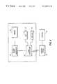
- FIG. 3is a block diagram of the cellular phone shown in FIG. 1 wherein the phone possesses local mute ringer capability.
- FIG. 4is a block diagram of the cellular phone shown in FIG. 1 wherein the phone possesses transfer-to-voicemail signaling capability.
- FIG. 5is a flow diagram of a method for screening incoming telephone calls utilizing a local mute ringer function.
- FIG. 6is a flow diagram of a method for screening incoming telephone calls utilizing a transfer-to-voicemail signaling function.
- a digital cellular phone 10 and a conventional desktop telephone 11are linked to a telephone network, not shown, that supports telecommunications connectivity with the phones.
- a digital cellular phoneis preferred over an analog cellular phone because its superior signaling capabilities are better suited to implement the silencer features to be described below.
- An antenna 12is attached to the cellular phone to enable reception of telephone signals from a central office or a signal relay station.
- Each phoneincludes at least one speaker 14 and 22 to enable the user of the telephone to hear speech transmitted over the network. Two modes of exchanging voice information are provided for communicating via the conventional desktop telephone of FIG. 2 .
- the handset 19conventionally includes both a microphone and a speaker that may be used in the first mode, or a speaker phone function can be employed utilizing the speaker 22 and microphone 24 located on the body of the conventional desktop telephone 11 .
- a liquid crystal display (LCD) 16 or an equivalent displayenables a user of the telephone 10 and 11 to view caller identification (ID) information as well as various icons indicating the assignment of functions to soft keys 18 positioned below the LCD.
- the caller identification informationpreferably includes the name of the calling party. However, call number indicator information can suffice to implement the silencer features.
- Digit keypads 20are provided to enable a user to enter the telephone number of a remote endpoint.
- the soft keys 18are positioned below the LCD 16 so that multiple icons can be displayed over each of the soft keys, thereby increasing the number of functions which can be assigned to each soft key so as to reduce the surface area on the telephone occupied by the soft keys.
- An indicator circuitis located within each telephone 10 and 11 to indicate receipt of an incoming call.
- the ringer circuitis connected to the speaker 22 , but the cellular phone 10 is shown as having a separate ringer 23 .
- the LCD 16 and digit keypads 20can be backlit and programmed to flash to indicate receipt of an incoming call during a silent ring mode.
- the conventional desktop telephone 11can be equipped with a remote control device 26 to enable a user to view the LCD 16 and to utilize the soft keys 18 when the user is not able to reach the telephone in a timely manner after it has begun ringing.
- the telephones 10 and 11 in FIGS. 1 and 2can be connected to any telephone network, digital or analog, including but not limited to a standard analog telephone network, an ISDN, an Internet Protocol telephony network, and a T-1 carrier.
- FIGS. 1 and 2illustrate a cellular telephone and a conventional telephone, any telephonic device can be configured to practice the claimed invention, including a personal computer configured for telephonic communication.
- FIG. 3illustrates a telephone equipped with a local mute ringer function.
- a call controller 36transmits and receives signaling messages to and from a central office 40 . For instance, the call controller transmits a message to the central office 40 containing the telephone number of a remote endpoint when the user attempts to place a telephone call. Furthermore, when the telephone 10 receives a call from a remote telephone (not shown), the call controller 36 may receive caller ID information from the central office. The call controller is connected to the LCD 16 to display the caller ID information to the user. The call controller also causes various icons to be displayed on the LCD 16 above the soft keys 18 in response to an incoming call. These icons include a mute ringer icon, the function of which will be discussed below.
- the call controlleris also connected to a ringer signal generator 32 to activate the ringer 23 upon receipt of an incoming telephone call.
- the call controlleris the component of the telephone which receives the call signaling messages from the central office.
- the controller 36processes these messages and instructs the ringer signal generator 32 to activate the ringer 23 .
- the call controller 36Upon receipt of an incoming telephone call, the call controller 36 also assigns a mute ringer function to one of the soft keys 18 .
- the mute ringer iconis presented on the LCD 16 to indicate to the user that the soft key 18 has been assigned the mute ringer function, so that depressing the soft key causes temporary deactivation of the ringer.
- the soft keyis connected to a ringer controller 28 which in turn is connected to a switch 30 , connected to the ringer signal generator 32 and the ringer 23 . Depression of the mute ringer soft key 18 causes the ringer controller 28 to open the switch 30 , so that the ringer signal generator is no longer capable of communicating with the ringer. Consequently, the ringer is muted.
- the ringer controllercould directly signal to the ringer signal generator to stop generating and transmitting ringer signals to the ringer 23 .
- a call status detector 34is connected to the call controller 36 and the ringer controller 28 .
- the call controllerreceives a message from the central office 40 when the incoming call is either transferred from the telephone 10 or is terminated prior to being transferred.
- the call status detectoris responsive to the message containing the call transfer or termination data and signals to the ringer controller 28 accordingly.
- the ringer controllerUpon receipt of a call transfer or termination signal from the call status detector, the ringer controller causes the switch 30 to close, thereby reestablishing communicative contact between the ringer signal generator 32 and the ringer 23 .
- the election to trigger the mute ringer functioni.e., the indicator-disabling mode of the telephone
- the election to trigger the mute ringer functionis executed on a call-by-call basis.
- the remote control device 26enables the user to ascertain the caller ID information and mute the ringer of the conventional desktop telephone 11 without the disruption of having to cross a room to read the information on the LCD of the telephone.
- the cellular telephoneis generally very accessible to the user because of its portable nature, the conventional desktop telephone might be located within the same room but at some distance from the user.
- the LCD 16 and the soft keys 18 of the remote control device 26are equipped for wireless communication with the call controller 36 and the ringer controller 28 . The means for such wireless communication are well known.
- FIG. 3shows the central office connected to a site enabled for voicemail functions.
- the telephone protocolpreferably includes a voicemail feature whereby, after a predetermined time interval, the central office 40 automatically transfers an incoming call to the voicemail site 42 and the caller has the option of leaving a message.
- PBXprivate branch exchange
- FIG. 4illustrates a telephone with a transfer-to-voicemail signaling capability.
- the transfer-to-voicemail functionis performed by way of communication with the central office 40 , or another telecommunications switching facility, such as a PBX.
- the call controller 36is enabled to mute the ringer by way of instantaneous communication with the central office 40 .
- the call controller 36causes the LCD 16 to display caller ID information and a transfer-to-voicemail icon upon receipt of a telephone call via the central office.
- the call controller 36also assigns a transfer-to-voicemail function to a soft key 18 . Depression of the transfer-to-voicemail soft key 18 causes the call controller 36 to transmit a transfer-to-voicemail message to the central office.
- the telephone callUpon receipt of the transfer-to-voicemail message, the telephone call is switched to a remote site 42 enabled for voicemail functions.
- the transfer of the telephone call from the telephonecauses the ringer 23 to stop ringing.
- the switchtransmits a message indicating the transfer of the call.
- the call controller 36Upon receipt of the call transfer message, the call controller 36 directs the ringer signal generator 32 to cease sending signals to the ringer 23 .
- An advantage provided by the telephone equipped with transfer-to-voicemail signaling capabilityis that the telephone can receive additional telephone calls immediately upon transfer of the incoming telephone call, whereas the telephone with local mute ringer capability cannot receive additional telephone calls until either the caller terminates the call or the call is transferred after expiration of the time-out period.
- a disadvantage of the telephone with instantaneous transfer-to-voicemail signaling capabilityis that the caller might deduce that the caller is being screened because of an abrupt transfer to voicemail.
- Combining the local mute ringer function with the transfer-to-voicemail signaling capability in a single telephoneprovides a user with the ability to select a screening method according to the particular needs of the user. For instance, if the user is expecting an important telephone call and it is of little consequence that a caller might be offended at having a call screened, the logical choice would be to employ the transfer-to-voicemail function to free the telephone as soon as possible for the important telephone call. If on the other hand the user is not awaiting an important telephone call and prefers to discreetly screen an incoming call without knowledge of the caller, then the user employs the local mute ringer function. As discussed above, the telephone illustrated in FIG. 3 is equipped to employ the local mute ringer function.
- the telephonecan also be configured to perform transfer-to-voicemail functions.
- the call controller 36is connected to the ringer signal generator 32 to activate and deactivate the ringer 23 .
- the call controller 36is also connected to the LCD 16 and must only be configured to cause the LCD 16 to display the transfer-to-voicemail icon, to assign to the soft key 18 the transfer-to-voicemail function, and the call controller must be programmed to transmit the transfer-to-voicemail message.
- FIG. 5illustrates a method for performing call screening utilizing the local mute ringer function with the telephone of FIG. 3 .
- a callis received by the call controller 36 from the central office 40 .
- the call controllerprocesses the call signaling data accompanying the call and in turn signals the LCD 16 to display the caller ID information and a mute ringer icon in step 46 .
- the call controller 36also causes the ringer signal generator 32 to generate and transmit ringer signals to the ringer 23 .
- the userdecides whether to answer the call based upon the caller ID information. If the user decides to answer the call, then no further steps are taken.
- step 50the mute ringer soft key 18 is depressed, thereby causing the ringer controller 28 to open the switch between the ringer signal generator 32 and the ringer 23 in step 52 . Opening the switch prevents ringer signals generated and transmitted by the ringer signal generator from reaching the ringer.
- an alternative to opening the switchwould be to use the ringer controller 28 to signal directly to the ringer signal generator 32 not to respond to the call controller 36 by transmitting ringer signals to the ringer 23 . It is important that the ringer not be deactivated for an interval longer than the duration of the call.
- the call status detector 34communicates with the call controller 36 to detect the termination of the call in step 54 .
- the call controller 36receives a signal from the central office 40 and the call controller causes the call status detector 34 to communicate to the ringer controller 28 that the call has been terminated or transferred.
- the ringer controllercauses the switch 30 to be closed, thereby reactivating the ringer 23 in step 56 .
- the ringer controllermight signal directly to the ringer signal generator 32 to resume responding to the appropriate signals from the call controller 36 by transmitting ringer signals to the ringer 23 .
- FIG. 6illustrates a method for screening calls employing the transfer-to-voicemail function in the telephone of FIGS. 3 and 4.
- a callis received from the central office.
- the call controller 36causes the LCD 16 to display caller ID information and a transfer-to-voicemail icon over a soft key in step 60 .
- the call controller 36also assigns a soft key 18 the transfer-to-voicemail function.
- the userdecides whether to answer the telephone call based on the caller ID information. If the user decides to answer the telephone call, then no further steps are taken. If the user decides not to answer the telephone call, then the user depresses the transfer-to-voicemail soft key 18 in step 64 .
- step 66the call controller 36 then transmits a transfer-to-voicemail message in response to the depression of the soft key 18 , causing the central office 40 or other remote switching facility to transfer the telephone call to a remote site 42 enabled for voicemail functions.
- the switching facilityUpon transfer of the telephone call, the switching facility transmits a disconnect message to the telephone indicating that the telephone call has been transferred.
- the call controller 36signals to the ringer signal generator 32 to cease transmitting ringer signals to the ringer 23 in step 70 .
- the method and apparatus described herein for screening telephone callsprovides flexible and efficient screening of unwanted telephone calls.
- the components which provide the ringer mute capabilityare integrally constructed into the telephone and so require no separate equipment.
- the claimed inventionenables the user of the telephone to make the determination of whether to answer calls on a call-by-call basis, while knowing the origin of the calls.
- the inventionprovides a user with two optional methods of screening.
- the local mute ringer functionprovides a discreet screening method which is transparent to the caller because, from the perspective of the caller, it appears that the call has simply been transferred after the standard number of rings. If an urgent call supercedes the need for discretion, then the user can employ the transfer-to-voicemail function which transfers the call to voicemail immediately, thereby freeing the telephone for other more important phone calls.
Landscapes
- Engineering & Computer Science (AREA)
- Computer Security & Cryptography (AREA)
- Signal Processing (AREA)
- Telephone Function (AREA)
Abstract
Description
Claims (14)
Priority Applications (1)
| Application Number | Priority Date | Filing Date | Title |
|---|---|---|---|
| US08/982,875US6400814B1 (en) | 1997-12-02 | 1997-12-02 | Telephone with ringer silencer screening feature |
Applications Claiming Priority (1)
| Application Number | Priority Date | Filing Date | Title |
|---|---|---|---|
| US08/982,875US6400814B1 (en) | 1997-12-02 | 1997-12-02 | Telephone with ringer silencer screening feature |
Publications (1)
| Publication Number | Publication Date |
|---|---|
| US6400814B1true US6400814B1 (en) | 2002-06-04 |
Family
ID=25529592
Family Applications (1)
| Application Number | Title | Priority Date | Filing Date |
|---|---|---|---|
| US08/982,875Expired - LifetimeUS6400814B1 (en) | 1997-12-02 | 1997-12-02 | Telephone with ringer silencer screening feature |
Country Status (1)
| Country | Link |
|---|---|
| US (1) | US6400814B1 (en) |
Cited By (30)
| Publication number | Priority date | Publication date | Assignee | Title |
|---|---|---|---|---|
| US20020197995A1 (en)* | 2001-06-25 | 2002-12-26 | Starkovich Alex D. | Method and apparatus for conditioning wireless transmission of messages |
| US6675002B1 (en)* | 1999-08-27 | 2004-01-06 | G. Jack Lipovski | System and method for automatically muting cellular telephone devices in noise sensitive areas |
| US20040174970A1 (en)* | 2003-03-04 | 2004-09-09 | Rutter William J. | Telephone line isolation device and method of use |
| US20040203674A1 (en)* | 2002-03-19 | 2004-10-14 | Guangming Shi | Multi-call display management for wireless communication devices |
| US6813491B1 (en) | 2001-08-31 | 2004-11-02 | Openwave Systems Inc. | Method and apparatus for adapting settings of wireless communication devices in accordance with user proximity |
| US20040252824A1 (en)* | 2003-06-12 | 2004-12-16 | Hummel Barbara Isabel | Ring control device |
| US20040264662A1 (en)* | 2003-06-30 | 2004-12-30 | Silver Edward Michael | Network-based timed ring suppression |
| US20040266490A1 (en)* | 2003-06-30 | 2004-12-30 | Silver Edward Michael | Timed ring suppressor |
| US20040264681A1 (en)* | 2003-06-30 | 2004-12-30 | Silver Edward Michael | Caller controlled network-based timed ring suppression |
| US20050018834A1 (en)* | 2003-07-25 | 2005-01-27 | Furnas William J. | Alert muting method through indirect contact for portable devices |
| US6888926B2 (en)* | 2001-03-16 | 2005-05-03 | Agere Systems Inc. | Extension telephone answering device and system employing same |
| US20050195952A1 (en)* | 2004-02-25 | 2005-09-08 | Dyer John C. | Telephone having ring stopping function |
| US20050201534A1 (en)* | 2004-03-10 | 2005-09-15 | Ignatin Gary R. | Method for call screening in a voice mail system |
| US6961413B2 (en) | 2003-02-19 | 2005-11-01 | Sarakas Stephen T | Residential telephone system and method |
| US20060156235A1 (en)* | 2003-03-03 | 2006-07-13 | Kiyoshi Kanazawa | Data input device, data input method, data input program, and computer-readable recording medium containing data input program |
| US20060166657A1 (en)* | 2005-01-25 | 2006-07-27 | Parag Patel | Remote caller ID projection device |
| US20060267917A1 (en)* | 2005-05-25 | 2006-11-30 | Cisco Technology, Inc. | System and method for managing an incoming communication |
| US20070041510A1 (en)* | 2005-05-20 | 2007-02-22 | Nec Infrontia Corporation | Telephone apparatus, telephone switchboard, and telephone line connection method |
| US7248864B1 (en)* | 2000-09-29 | 2007-07-24 | Palmsource, Inc. | System and method of managing incoming calls on a mobile device having an earplug |
| US20080055396A1 (en)* | 2006-08-30 | 2008-03-06 | Inventec Multimedia & Telecom Corporation | Video phone communication system and method therefor |
| US20080055394A1 (en)* | 2006-08-17 | 2008-03-06 | Inventec Multimedia & Telecom Corporation | Video phone device |
| US7352854B1 (en) | 2003-09-29 | 2008-04-01 | At&T Delaware Intellectual Property, Inc. | Call waiting suppression |
| US20080165022A1 (en)* | 2007-01-07 | 2008-07-10 | Scott Herz | Portable Electronic Device with Alert Silencing |
| US7443967B1 (en) | 2003-09-29 | 2008-10-28 | At&T Intellectual Property I, L.P. | Second communication during ring suppression |
| US20110028168A1 (en)* | 2005-08-08 | 2011-02-03 | David Champlin | Method and device for enabling message responses to incoming phone calls |
| US20110151841A1 (en)* | 2009-12-17 | 2011-06-23 | Shenzhen Futaihong Precision Industry Co., Ltd. | Call disconnect system and method for a mobile device |
| US8050387B1 (en)* | 1998-10-19 | 2011-11-01 | Siemens Aktiengesellschaft | Method and system for providing customized audio responses to incoming phone calls |
| US9860376B1 (en)* | 2016-01-15 | 2018-01-02 | Aaron Foss | Call screening device |
| US20190251803A1 (en)* | 2018-02-09 | 2019-08-15 | Goldtek Technology Co., Ltd. | Ringer control device and ringer control method |
| US11627412B2 (en)* | 2009-03-04 | 2023-04-11 | Apple Inc. | Portable electronic device control |
Citations (14)
| Publication number | Priority date | Publication date | Assignee | Title |
|---|---|---|---|---|
| US4384171A (en) | 1980-12-15 | 1983-05-17 | Klee Maurice M | Automatic telephone silencer |
| US4385295A (en)* | 1981-09-29 | 1983-05-24 | Motorola, Inc. | Pager with visible display indicating unread messages |
| US5191607A (en)* | 1990-10-09 | 1993-03-02 | Motorola, Inc. | Ring tone muting with disable |
| US5327486A (en)* | 1993-03-22 | 1994-07-05 | Bell Communications Research, Inc. | Method and system for managing telecommunications such as telephone calls |
| US5351289A (en) | 1992-09-17 | 1994-09-27 | Logsdon William K | Caller ID telephone security device |
| US5473667A (en)* | 1990-07-06 | 1995-12-05 | Neustein; Simon | Paging system with third party authorization |
| US5497413A (en)* | 1990-06-08 | 1996-03-05 | Kabushiki Kaisha Toshiba | Telephone system with message recording function |
| US5533102A (en)* | 1993-09-22 | 1996-07-02 | Active Voice | Telephone auto attendant system for delivering chosen greetings to callers while on the phone |
| US5604797A (en)* | 1995-12-19 | 1997-02-18 | Adcock; Stanley J. | Ring-tone muting device and processing method |
| US5619568A (en)* | 1995-07-24 | 1997-04-08 | Sony Corporation | Cordless phone with time-out controlled ringer |
| US5751793A (en)* | 1995-03-14 | 1998-05-12 | U S West Technologies, Inc. | Method and instructions for visual voice messaging user interface |
| US5781613A (en)* | 1996-06-17 | 1998-07-14 | Casio Phonemate, Inc. | Telephone answering device and method for screening incoming telephone calls with blocked calling party identification information |
| US5805587A (en)* | 1995-11-27 | 1998-09-08 | At&T Corp. | Call notification feature for a telephone line connected to the internet |
| US5812648A (en)* | 1996-02-20 | 1998-09-22 | Micron Technology, Inc. | Telephone ringer control device |
- 1997
- 1997-12-02USUS08/982,875patent/US6400814B1/ennot_activeExpired - Lifetime
Patent Citations (14)
| Publication number | Priority date | Publication date | Assignee | Title |
|---|---|---|---|---|
| US4384171A (en) | 1980-12-15 | 1983-05-17 | Klee Maurice M | Automatic telephone silencer |
| US4385295A (en)* | 1981-09-29 | 1983-05-24 | Motorola, Inc. | Pager with visible display indicating unread messages |
| US5497413A (en)* | 1990-06-08 | 1996-03-05 | Kabushiki Kaisha Toshiba | Telephone system with message recording function |
| US5473667A (en)* | 1990-07-06 | 1995-12-05 | Neustein; Simon | Paging system with third party authorization |
| US5191607A (en)* | 1990-10-09 | 1993-03-02 | Motorola, Inc. | Ring tone muting with disable |
| US5351289A (en) | 1992-09-17 | 1994-09-27 | Logsdon William K | Caller ID telephone security device |
| US5327486A (en)* | 1993-03-22 | 1994-07-05 | Bell Communications Research, Inc. | Method and system for managing telecommunications such as telephone calls |
| US5533102A (en)* | 1993-09-22 | 1996-07-02 | Active Voice | Telephone auto attendant system for delivering chosen greetings to callers while on the phone |
| US5751793A (en)* | 1995-03-14 | 1998-05-12 | U S West Technologies, Inc. | Method and instructions for visual voice messaging user interface |
| US5619568A (en)* | 1995-07-24 | 1997-04-08 | Sony Corporation | Cordless phone with time-out controlled ringer |
| US5805587A (en)* | 1995-11-27 | 1998-09-08 | At&T Corp. | Call notification feature for a telephone line connected to the internet |
| US5604797A (en)* | 1995-12-19 | 1997-02-18 | Adcock; Stanley J. | Ring-tone muting device and processing method |
| US5812648A (en)* | 1996-02-20 | 1998-09-22 | Micron Technology, Inc. | Telephone ringer control device |
| US5781613A (en)* | 1996-06-17 | 1998-07-14 | Casio Phonemate, Inc. | Telephone answering device and method for screening incoming telephone calls with blocked calling party identification information |
Cited By (59)
| Publication number | Priority date | Publication date | Assignee | Title |
|---|---|---|---|---|
| US8050387B1 (en)* | 1998-10-19 | 2011-11-01 | Siemens Aktiengesellschaft | Method and system for providing customized audio responses to incoming phone calls |
| US7363042B2 (en) | 1999-08-27 | 2008-04-22 | Lipovski G Jack | Cell phone muting override system |
| US6675002B1 (en)* | 1999-08-27 | 2004-01-06 | G. Jack Lipovski | System and method for automatically muting cellular telephone devices in noise sensitive areas |
| US20040087318A1 (en)* | 1999-08-27 | 2004-05-06 | Lipovski G. Jack | Apparatus and method for automatically muting restricted electronic devices in restricted areas |
| US20070049264A1 (en)* | 1999-08-27 | 2007-03-01 | Lipovski G Jack | Cell phone muting override system |
| US7142877B2 (en) | 1999-08-27 | 2006-11-28 | Lipovski G Jack | Apparatus and method for automatically muting restricted electronic devices in restricted areas |
| US7248864B1 (en)* | 2000-09-29 | 2007-07-24 | Palmsource, Inc. | System and method of managing incoming calls on a mobile device having an earplug |
| US20070263827A1 (en)* | 2000-09-29 | 2007-11-15 | Palmsource, Inc. | System and method of receiving a call having an identified or unidentified number and an identified or unidentified name |
| US6888926B2 (en)* | 2001-03-16 | 2005-05-03 | Agere Systems Inc. | Extension telephone answering device and system employing same |
| US20020197995A1 (en)* | 2001-06-25 | 2002-12-26 | Starkovich Alex D. | Method and apparatus for conditioning wireless transmission of messages |
| US6813491B1 (en) | 2001-08-31 | 2004-11-02 | Openwave Systems Inc. | Method and apparatus for adapting settings of wireless communication devices in accordance with user proximity |
| US7787908B2 (en)* | 2002-03-19 | 2010-08-31 | Qualcomm Incorporated | Multi-call display management for wireless communication devices |
| US20040203674A1 (en)* | 2002-03-19 | 2004-10-14 | Guangming Shi | Multi-call display management for wireless communication devices |
| US7715539B2 (en) | 2003-02-19 | 2010-05-11 | Sarakas Stephen T | Residential telephone system and method |
| US6961413B2 (en) | 2003-02-19 | 2005-11-01 | Sarakas Stephen T | Residential telephone system and method |
| US20060008062A1 (en)* | 2003-02-19 | 2006-01-12 | Sarakas Stephen T | Residential telephone system and method |
| US20060156235A1 (en)* | 2003-03-03 | 2006-07-13 | Kiyoshi Kanazawa | Data input device, data input method, data input program, and computer-readable recording medium containing data input program |
| US6944293B2 (en) | 2003-03-04 | 2005-09-13 | William J. Rutter | Telephone line isolation device and method of use |
| US20040174970A1 (en)* | 2003-03-04 | 2004-09-09 | Rutter William J. | Telephone line isolation device and method of use |
| US20040252824A1 (en)* | 2003-06-12 | 2004-12-16 | Hummel Barbara Isabel | Ring control device |
| US7020271B2 (en)* | 2003-06-12 | 2006-03-28 | Barbara Isabel Hummel | Ring control device |
| US20070121921A1 (en)* | 2003-06-30 | 2007-05-31 | Silver Edward M | Network-based timed ring suppression |
| US9426280B2 (en)* | 2003-06-30 | 2016-08-23 | At&T Intellectual Property I, L.P. | Network-based timed ring suppression |
| US7113586B2 (en) | 2003-06-30 | 2006-09-26 | Edward Michael Silver | Caller controlled network-based timed ring suppression |
| US20070121920A1 (en)* | 2003-06-30 | 2007-05-31 | Silver Edward M | Caller controlled network-based timed ring suppression |
| US20140003592A1 (en)* | 2003-06-30 | 2014-01-02 | At&T Intellectual Property I, L.P. | Network-Based Timed Ring Suppression |
| US7239693B2 (en) | 2003-06-30 | 2007-07-03 | Bellsouth Intellectual Property Corporation | Network-based timed ring suppression |
| US8548158B2 (en)* | 2003-06-30 | 2013-10-01 | At&T Intellectual Property I, L. P. | Network based timed ring suppression |
| US20040264662A1 (en)* | 2003-06-30 | 2004-12-30 | Silver Edward Michael | Network-based timed ring suppression |
| US20040266490A1 (en)* | 2003-06-30 | 2004-12-30 | Silver Edward Michael | Timed ring suppressor |
| US20040264681A1 (en)* | 2003-06-30 | 2004-12-30 | Silver Edward Michael | Caller controlled network-based timed ring suppression |
| US7529564B2 (en) | 2003-06-30 | 2009-05-05 | At&T Intellectual Property I, L.P. | Timed ring suppressor |
| US20050018834A1 (en)* | 2003-07-25 | 2005-01-27 | Furnas William J. | Alert muting method through indirect contact for portable devices |
| US7162026B2 (en)* | 2003-07-25 | 2007-01-09 | William J Furnas | Alert muting method through indirect contact for portable devices |
| US8619954B2 (en) | 2003-09-29 | 2013-12-31 | At&T Intellectual Property I, L.P. | Methods, systems, and products for ring suppression |
| US7443967B1 (en) | 2003-09-29 | 2008-10-28 | At&T Intellectual Property I, L.P. | Second communication during ring suppression |
| US7352854B1 (en) | 2003-09-29 | 2008-04-01 | At&T Delaware Intellectual Property, Inc. | Call waiting suppression |
| US9936069B2 (en) | 2003-09-29 | 2018-04-03 | At&T Intellectual Property I, L.P. | Methods, systems, and products for suppression of alerts |
| US9525774B2 (en) | 2003-09-29 | 2016-12-20 | At&T Intellectual Property I, L.P. | Methods, systems, and products for suppression of alerts |
| US9137382B2 (en) | 2003-09-29 | 2015-09-15 | At&T Intellectual Property I, L.P. | Methods, systems, and products for suppression of alerts |
| US20050195952A1 (en)* | 2004-02-25 | 2005-09-08 | Dyer John C. | Telephone having ring stopping function |
| US20050201534A1 (en)* | 2004-03-10 | 2005-09-15 | Ignatin Gary R. | Method for call screening in a voice mail system |
| US20060166657A1 (en)* | 2005-01-25 | 2006-07-27 | Parag Patel | Remote caller ID projection device |
| US20070041510A1 (en)* | 2005-05-20 | 2007-02-22 | Nec Infrontia Corporation | Telephone apparatus, telephone switchboard, and telephone line connection method |
| US20060267917A1 (en)* | 2005-05-25 | 2006-11-30 | Cisco Technology, Inc. | System and method for managing an incoming communication |
| US8737578B2 (en) | 2005-08-08 | 2014-05-27 | Qualcomm Incorporated | Method and device for enabling message responses to incoming phone calls |
| US8311189B2 (en)* | 2005-08-08 | 2012-11-13 | Hewlett-Packard Development Company, L.P. | Method and device for enabling message responses to incoming phone calls |
| US20110028168A1 (en)* | 2005-08-08 | 2011-02-03 | David Champlin | Method and device for enabling message responses to incoming phone calls |
| US20080055394A1 (en)* | 2006-08-17 | 2008-03-06 | Inventec Multimedia & Telecom Corporation | Video phone device |
| US8054328B2 (en) | 2006-08-30 | 2011-11-08 | Inventec Multimedia & Telecom Corporation | Video phone communication system and method therefor |
| US20080055396A1 (en)* | 2006-08-30 | 2008-03-06 | Inventec Multimedia & Telecom Corporation | Video phone communication system and method therefor |
| US20080165022A1 (en)* | 2007-01-07 | 2008-07-10 | Scott Herz | Portable Electronic Device with Alert Silencing |
| US7671756B2 (en)* | 2007-01-07 | 2010-03-02 | Apple Inc. | Portable electronic device with alert silencing |
| US11627412B2 (en)* | 2009-03-04 | 2023-04-11 | Apple Inc. | Portable electronic device control |
| CN102104667B (en)* | 2009-12-17 | 2013-10-09 | 深圳富泰宏精密工业有限公司 | Mobile phone and on-hook method thereof |
| US20110151841A1 (en)* | 2009-12-17 | 2011-06-23 | Shenzhen Futaihong Precision Industry Co., Ltd. | Call disconnect system and method for a mobile device |
| US8320973B2 (en)* | 2009-12-17 | 2012-11-27 | Shenzhen Futaihong Precision Industry Co., Ltd. | Call disconnect system and method for a mobile device |
| US9860376B1 (en)* | 2016-01-15 | 2018-01-02 | Aaron Foss | Call screening device |
| US20190251803A1 (en)* | 2018-02-09 | 2019-08-15 | Goldtek Technology Co., Ltd. | Ringer control device and ringer control method |
Similar Documents
| Publication | Publication Date | Title |
|---|---|---|
| US6400814B1 (en) | Telephone with ringer silencer screening feature | |
| US6002763A (en) | Telephone with a mute ringer function having an automatic ringer reactivation capability | |
| US6148213A (en) | Method and apparatus for accessing a telephone answering device from a cordless telephone portable unit | |
| CA2235492C (en) | Method for monitoring voicemail calls using adsi capable cpe | |
| KR0135287B1 (en) | Terminal switching control apparatus | |
| US5701338A (en) | Call box with keyboard communication | |
| JPH0652914B2 (en) | Caller telephone number display | |
| US6662026B1 (en) | Apparatus and method for detecting and handling accidental dialing on a mobile communications device | |
| KR0164372B1 (en) | How to implement automatic call in wireless | |
| US6456696B1 (en) | Method and apparatus for temporarily deactivating a call indicator | |
| US6130936A (en) | System and method for terminating a telephone call after simulating a telephone connection failure | |
| JPH07327074A (en) | Auxiliary baseband telephone interface for responder | |
| JPH0243855A (en) | wireless telephone equipment | |
| KR930002882B1 (en) | Cordless Telephone Device | |
| US5638437A (en) | Telecommunication system and method enabling a user to get access to an automated call processing from a central station operating on pulse dialling mode | |
| WO1999057880A1 (en) | Programmable time-controlled functions in mobile terminal handsets | |
| JP3737273B2 (en) | Button telephone apparatus and incoming call reception method thereof | |
| KR960003104B1 (en) | Wireless calling devices for keyphone system | |
| JP3398029B2 (en) | Telephone equipment | |
| JP3567189B2 (en) | Key telephone equipment | |
| JP3088379B2 (en) | Communication terminal device with speakerphone call function | |
| JPH06252839A (en) | Cordless button telephone device | |
| KR20000001188A (en) | Remote control method of morning call | |
| EP0198913A1 (en) | Call unit for use in an emergency call system | |
| KR200240708Y1 (en) | Transmission of the sound of a language for one-button dialing system |
Legal Events
| Date | Code | Title | Description |
|---|---|---|---|
| AS | Assignment | Owner name:SIEMENS BUSINESS COMMUNICATION SYSTEMS, INC., CALI Free format text:ASSIGNMENT OF ASSIGNORS INTEREST;ASSIGNOR:ADAMS, JOEL;REEL/FRAME:008874/0831 Effective date:19971112 | |
| AS | Assignment | Owner name:SIEMENS INFORMATION AND COMMUNICATION MOBILE LLC, Free format text:CHANGE OF NAME;ASSIGNOR:SIEMENS INFORMATION AND COMMUNICATION PRODUCTS, LLC;REEL/FRAME:012796/0387 Effective date:20000417 Owner name:SIEMENS INFORMATION AND COMMUNICATION NETWORKS, CA Free format text:MERGER;ASSIGNOR:SIEMENS BUISNESS COMMUNICATION SYSTEMS, INC.;REEL/FRAME:012796/0400 Effective date:19980913 Owner name:SIEMENS INFORMATION AND COMMUNICATION PRODUCTS, LL Free format text:MERGER;ASSIGNOR:SIEMENS INFORMATION AND COMMUNICATION NETWORKS, INC.;REEL/FRAME:012796/0396 Effective date:20000417 | |
| STCF | Information on status: patent grant | Free format text:PATENTED CASE | |
| FPAY | Fee payment | Year of fee payment:4 | |
| AS | Assignment | Owner name:SIEMENS INFORMATION & COMMUNICATION NETWORKS, INC. Free format text:MERGER AND NAME CHANGE;ASSIGNOR:SIEMENS INFORMATION & COMMUNICATION MOBILE, LLC;REEL/FRAME:020403/0205 Effective date:20041001 | |
| AS | Assignment | Owner name:SIEMENS AKTIENGESELLSCHAFT, GERMANY Free format text:ASSIGNMENT OF ASSIGNORS INTEREST;ASSIGNOR:SIEMENS COMMUNICATIONS, INC.;REEL/FRAME:021006/0556 Effective date:20080507 | |
| FEPP | Fee payment procedure | Free format text:PAYOR NUMBER ASSIGNED (ORIGINAL EVENT CODE: ASPN); ENTITY STATUS OF PATENT OWNER: LARGE ENTITY | |
| FPAY | Fee payment | Year of fee payment:8 | |
| AS | Assignment | Owner name:STAR CO SCIENTIFIC TECHNOLOGIES ADVANCED RESEARCH Free format text:ASSIGNMENT OF ASSIGNORS INTEREST;ASSIGNOR:SIEMENS AKTIENGESELLSCHAFT;REEL/FRAME:031505/0249 Effective date:20130705 Owner name:BLUEBONNET TELECOMMUNICATIONS, LLC, TEXAS Free format text:ASSIGNMENT OF ASSIGNORS INTEREST;ASSIGNOR:STAR CO SCIENTIFIC TECHNOLOGIES ADVANCED RESEARCH CO., LLC DBA STAR CO;REEL/FRAME:031487/0982 Effective date:20131021 | |
| FPAY | Fee payment | Year of fee payment:12 | |
| AS | Assignment | Owner name:RPX CORPORATION, CALIFORNIA Free format text:ASSIGNMENT OF ASSIGNORS INTEREST;ASSIGNOR:BLUEBONNET TELECOMMUNICATIONS;REEL/FRAME:037679/0753 Effective date:20150225 | |
| AS | Assignment | Owner name:JPMORGAN CHASE BANK, N.A., AS COLLATERAL AGENT, IL Free format text:SECURITY AGREEMENT;ASSIGNORS:RPX CORPORATION;RPX CLEARINGHOUSE LLC;REEL/FRAME:038041/0001 Effective date:20160226 | |
| AS | Assignment | Owner name:RPX CORPORATION, CALIFORNIA Free format text:RELEASE (REEL 038041 / FRAME 0001);ASSIGNOR:JPMORGAN CHASE BANK, N.A.;REEL/FRAME:044970/0030 Effective date:20171222 Owner name:RPX CLEARINGHOUSE LLC, CALIFORNIA Free format text:RELEASE (REEL 038041 / FRAME 0001);ASSIGNOR:JPMORGAN CHASE BANK, N.A.;REEL/FRAME:044970/0030 Effective date:20171222 |