US6400803B1 - Voice over digital subscriber line call redirection for lifeline service - Google Patents
Voice over digital subscriber line call redirection for lifeline serviceDownload PDFInfo
- Publication number
- US6400803B1 US6400803B1US09/375,709US37570999AUS6400803B1US 6400803 B1US6400803 B1US 6400803B1US 37570999 AUS37570999 AUS 37570999AUS 6400803 B1US6400803 B1US 6400803B1
- Authority
- US
- United States
- Prior art keywords
- subscriber
- local
- port
- customer premises
- premises equipment
- Prior art date
- Legal status (The legal status is an assumption and is not a legal conclusion. Google has not performed a legal analysis and makes no representation as to the accuracy of the status listed.)
- Expired - Lifetime
Links
- 238000000034methodMethods0.000claimsdescription20
- 230000011664signalingEffects0.000claimsdescription10
- XUIMIQQOPSSXEZ-UHFFFAOYSA-NSiliconChemical compound[Si]XUIMIQQOPSSXEZ-UHFFFAOYSA-N0.000claimsdescription2
- 230000002401inhibitory effectEffects0.000claimsdescription2
- 229910052710siliconInorganic materials0.000claimsdescription2
- 239000010703siliconSubstances0.000claimsdescription2
- 206010010099Combined immunodeficiencyDiseases0.000description3
- 230000000694effectsEffects0.000description3
- 230000007704transitionEffects0.000description3
- RYGMFSIKBFXOCR-UHFFFAOYSA-NCopperChemical compound[Cu]RYGMFSIKBFXOCR-UHFFFAOYSA-N0.000description2
- 108010076504Protein Sorting SignalsProteins0.000description2
- 230000005540biological transmissionEffects0.000description2
- 229910052802copperInorganic materials0.000description2
- 239000010949copperSubstances0.000description2
- 238000001514detection methodMethods0.000description2
- 238000009434installationMethods0.000description2
- 238000013507mappingMethods0.000description2
- 101150012579ADSL geneProteins0.000description1
- 102100020775Adenylosuccinate lyaseHuman genes0.000description1
- 108700040193Adenylosuccinate lyasesProteins0.000description1
- 230000000903blocking effectEffects0.000description1
- 238000001360collision-induced dissociationMethods0.000description1
- 238000004891communicationMethods0.000description1
- 230000008878couplingEffects0.000description1
- 238000010168coupling processMethods0.000description1
- 238000005859coupling reactionMethods0.000description1
- 238000005516engineering processMethods0.000description1
- 208000002343primary orthostatic tremorDiseases0.000description1
- 238000012545processingMethods0.000description1
- 238000012546transferMethods0.000description1
Images


Classifications
- H—ELECTRICITY
- H04—ELECTRIC COMMUNICATION TECHNIQUE
- H04M—TELEPHONIC COMMUNICATION
- H04M3/00—Automatic or semi-automatic exchanges
- H04M3/08—Indicating faults in circuits or apparatus
- H04M3/12—Marking faulty circuits "busy"; Enabling equipment to disengage itself from faulty circuits ; Using redundant circuits; Response of a circuit, apparatus or system to an error
- H—ELECTRICITY
- H04—ELECTRIC COMMUNICATION TECHNIQUE
- H04M—TELEPHONIC COMMUNICATION
- H04M11/00—Telephonic communication systems specially adapted for combination with other electrical systems
- H04M11/06—Simultaneous speech and data transmission, e.g. telegraphic transmission over the same conductors
- H04M11/062—Simultaneous speech and data transmission, e.g. telegraphic transmission over the same conductors using different frequency bands for speech and other data
- H—ELECTRICITY
- H04—ELECTRIC COMMUNICATION TECHNIQUE
- H04Q—SELECTING
- H04Q11/00—Selecting arrangements for multiplex systems
- H04Q11/04—Selecting arrangements for multiplex systems for time-division multiplexing
- H04Q11/0428—Integrated services digital network, i.e. systems for transmission of different types of digitised signals, e.g. speech, data, telecentral, television signals
- H04Q11/0478—Provisions for broadband connections
- H—ELECTRICITY
- H04—ELECTRIC COMMUNICATION TECHNIQUE
- H04L—TRANSMISSION OF DIGITAL INFORMATION, e.g. TELEGRAPHIC COMMUNICATION
- H04L12/00—Data switching networks
- H04L12/54—Store-and-forward switching systems
- H04L12/56—Packet switching systems
- H04L12/5601—Transfer mode dependent, e.g. ATM
- H04L2012/5614—User Network Interface
- H04L2012/5616—Terminal equipment, e.g. codecs, synch.
- H—ELECTRICITY
- H04—ELECTRIC COMMUNICATION TECHNIQUE
- H04L—TRANSMISSION OF DIGITAL INFORMATION, e.g. TELEGRAPHIC COMMUNICATION
- H04L12/00—Data switching networks
- H04L12/54—Store-and-forward switching systems
- H04L12/56—Packet switching systems
- H04L12/5601—Transfer mode dependent, e.g. ATM
- H04L2012/5629—Admission control
- H04L2012/563—Signalling, e.g. protocols, reference model
- H—ELECTRICITY
- H04—ELECTRIC COMMUNICATION TECHNIQUE
- H04L—TRANSMISSION OF DIGITAL INFORMATION, e.g. TELEGRAPHIC COMMUNICATION
- H04L12/00—Data switching networks
- H04L12/54—Store-and-forward switching systems
- H04L12/56—Packet switching systems
- H04L12/5601—Transfer mode dependent, e.g. ATM
- H04L2012/5638—Services, e.g. multimedia, GOS, QOS
- H04L2012/5646—Cell characteristics, e.g. loss, delay, jitter, sequence integrity
- H04L2012/5652—Cell construction, e.g. including header, packetisation, depacketisation, assembly, reassembly
- H04L2012/5653—Cell construction, e.g. including header, packetisation, depacketisation, assembly, reassembly using the ATM adaptation layer [AAL]
- H04L2012/5656—Cell construction, e.g. including header, packetisation, depacketisation, assembly, reassembly using the ATM adaptation layer [AAL] using the AAL2
- H—ELECTRICITY
- H04—ELECTRIC COMMUNICATION TECHNIQUE
- H04L—TRANSMISSION OF DIGITAL INFORMATION, e.g. TELEGRAPHIC COMMUNICATION
- H04L12/00—Data switching networks
- H04L12/54—Store-and-forward switching systems
- H04L12/56—Packet switching systems
- H04L12/5601—Transfer mode dependent, e.g. ATM
- H04L2012/5638—Services, e.g. multimedia, GOS, QOS
- H04L2012/5671—Support of voice
- H—ELECTRICITY
- H04—ELECTRIC COMMUNICATION TECHNIQUE
- H04M—TELEPHONIC COMMUNICATION
- H04M19/00—Current supply arrangements for telephone systems
Definitions
- the present inventionrelates to a method and apparatus for lifeline call redirection in a voice over digital subscriber line system, and a system incorporating the same.
- VoDSLVoice over DSL
- a VoDSL systemmay provide 4 voice channels carried within the digital data over a single twisted pair subscriber loop from a Line Terminating Equipment (LTE) located in the Central Office to a Customer Premises Equipment (CPE).
- LTELine Terminating Equipment
- CPECustomer Premises Equipment
- a VoDSL systemcarries the voice channel(s) in band as encoded data within the data stream and therefore there is no baseband POTS (Plain Old Telephony Service) as would be the case with for example ADSL or G.Lite.
- POTSPhase Old Telephony Service
- VoDSL modemsConventional analogue POTS telephony over a twisted pair to the LTE has the benefit that during power failure at the customer premises emergency calls can still be placed since the line and the handset at the customer premises are powered from the central office.
- a disadvantage of existing VoDSL modemsis that the amount of power required for normal operation could severely limit the operational loop length if power is fed from the central office and not provide a service able to reach the majority of consumers. This has limited deployment of VoDSL systems to subscribers having an additional conventional POTS line which can be used in the event of power failure. Absence of support for lifeline services has therefore severely hindered deployment into the small business and especially the residential market.
- the inventionseeks to provide an improved method and apparatus for providing lifeline call support in a voice over digital subscriber loop system.
- customer premises equipment arrangementfor a telecommunications subscriber, the arrangement comprising a subscriber loop port; a plurality of switchable local subscriber ports; and a router circuit; wherein each of said plurality of local subscriber ports is switchably connectable in parallel to said subscriber loop port and wherein said router is arranged to monitor signals received at said subscriber loop port and to selectively disconnect at least one of said local subscriber ports responsive to said signals.
- customer premises equipment arrangementfor a telecommunications subscriber and adapted to provide a lifeline voice service under a fault condition, the arrangement comprising a subscriber loop port whereby the arrangement is coupled to the subscriber loop; a plurality of switchable local subscriber ports each providing access to a respective telephone instrument; and a router circuit whereby, under normal conditions, voice calls may be routed each to a respective loop port; wherein each of said plurality of local subscriber ports is switchably connectable in parallel to said subscriber loop port and wherein said router is arranged to monitor signals received at said subscriber loop port and to selectively provide and maintain voice access to one said loop port under a said fault condition.
- the inventionis also directed to a method by which the described apparatus operates and including method steps for carrying out every function of the apparatus.
- a method of operating a customer premises equipment arrangementcomprising a subscriber loop port and a plurality of local subscriber ports selectively connectable to said subscriber loop port; the method comprising the steps of: receiving signal at said subscriber loop port indicative of a local port; and selectively coupling one of said local subscriber ports to said subscriber loop port responsive to said signal.
- a method of operating a customer premises equipment arrangementcomprising a subscriber loop port coupled with a subscriber loop to a line termination equipment and having a plurality of local subscriber ports each connectable to a telephone instrument so as to provide a voice over digital subscriber line service to each said telephone instrument, the method comprising routing incoming voice calls each to a respective local point determined from signalling associated with that call, and, under a fault condition in each customer premises equipment arrangement, routing an incoming voice call to a selected one of said local ports and inhibiting further incoming calls while that call is in progress.
- the inventionalso provides for a system for the purposes of digital signal processing which comprises one or more instances of apparatus embodying the present invention, together with other additional apparatus.
- the subscriber equipment described belowoperates, during power fail or modem failure at the CPE, so as to automatically map any incoming telephone calls to a CPE system to the designated “lifeline” POTS ‘phone port. In this way, an external incoming call to any of the derived telephone ports at the CPE will be terminated at the designated “lifeline” POTS port. It is assumed that the installation will be such that the “lifeline” telephone (or telephones on extension) will be known and physically accessible by all users (such as a small office environment).
- Automatic redirection of all in-band telephony channels to one “lifeline” telephone portmay be effected and blocking of incoming calls to non-lifeline logical telephony ports due to VoDSL “lifeline” invocation is eliminated.
- the LEis signalled during “lifeline” invocation and repeal to indicate VoDSL “lifeline” status.
- FIG. 1shows a first embodiment of a system in accordance with the present invention
- FIG. 2shows a second embodiment of a system in accordance with the present invention
- FIGS. 3 and 4show two distinct states of customer premises equipment arrangement in accordance with the present invention
- FIG. 5shows a example signal sequence from central office to customer premises equipment in accordance with the present invention.
- FIG. 6shows a further embodiment of CPE similar to FIG. 3, but with four added bi-directional switches.
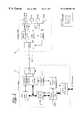
- thisdepicts a first preferred exemplary embodiment in which DSL communication is provided over a subscriber line 11 between customer premises equipment (CPE) 12 and a line termination equipment or access multiplexer 13 .
- the CPEdelivers services including voice services via a number of ports, and also incorporates a ‘lifeline’ port whereby a voice service is maintained to the subscriber in the event of a power failure at the CPE.
- the voice and signalling informationis carried over ATM with the individual voice traffic channels being carried as ALL2 mini-cells with identifying CIDs.
- the mappingis then performed by terminating the signalling within the access MUX and translating the CID of the incoming voice channel to the CID of the “lifeline” traffic channel (and vice-versa for outgoing mini-cells).
- the CPE equipmentwill then behave in the same fashion no matter which of its logical ‘phones are called.
- the correct termination of the signallingis crucial to the desired operation.
- the access MUXmust signal back to the Local Exchange (LE) to ensure that the call is set up as normal (provided that the “lifeline” ‘phone is not engaged) and to ensure that the remaining logical ‘phones are made unavailable or engaged. Entry to and exit from “lifeline” mode is controlled is and appropriately signalled to the LE. Entry into “lifeline” mode is likely to be forced and any existing calls dropped. It is also desirable that “lifeline” mode will only be exited when the CPE “lifeline” ‘phone port has an on-hook status—this prevents any in-progress call (possible an emergency) from being interrupted.
- LLocal Exchange
- a second preferred exemplary embodimentinvolves the CPE signalling to the LE that “lifeline” service has been invoked for a particular CPE.
- the LEmust then perform the mapping/call diversion of any incoming call to the “lifeline” ‘phone number and again force the non-lifeline ‘phones to be unavailable or engaged.
- entry and exit from “lifeline” modeshould be carefully controlled in the same way.
- Voice over DSLis a means of supplying a number of derived POTS circuits along with data over a single copper loop. These POTS circuits will present themselves as conventional interfaces for direct connection to a standard telephone. There is a requirement to ensure the use of at least one telephone in the event of an emergency for lifeline.
- the method of provisioning for lifeline POTSis to use an analogue POTs capable linecard at the Central Office end of the loop, which would detect that loss of the DSL link by some means and switch the line over to the lifeline analogue linecard with its battery feed.
- the conventional analogue telephonesare directly connected to the loop via some form of switching. This switching, possibly in the form of relays, should be such that, in their un-powered lifeline state, the direct connection is made, bypassing the modem.
- the arrangementprovides a method of directing an incoming call to a particular phone.
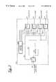
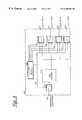
- FIG. 3an apparatus and method is described for routing an incoming call at the CPE to a particular POTS outlet when a DSL modem CPE arrangement is in lifeline mode.
- the CPE 300comprises four relays 301 , 331 - 4 , a DSL modem 310 , and a lifeline router 320 . It also comprises a subscriber loop port 340 , and four local subscriber ports 351 - 4 .
- Subscriber loop port 340is connected via switch 301 to the DSL modem 310 which in turn is connected to each of the four ports 351 - 4 via switches 331 - 4 respectively.
- the subscriber loop portis also connected via switch 301 by a direct connection to switches 331 - 4 to ports 351 , 354 respectively.
- Lifeline router 320is arranged to receive the signal passing between switch 301 and switches 331 - 4 and to provide as output signals on outputs 321 - 4 which provide control signals to switches 331 - 4 respectively.
- switch 301In normal operation when local power is provided to the CPE 300 switch 301 connects between the subscriber loop port and the DSL modem 310 and similarly switches 331 - 4 are operated to provide direct connections from the DSL modem 310 to ports 351 - 4 respectively. Upon loss of local power the switches 301 , 331 - 4 are arranged to default (as shown in FIG. 3) to provide a direct connection from the subscriber loop port 340 via the direct link to switches 331 - 4 and hence to local subscriber ports 351 - 4 respectively. In lifeline mode only one channel can be supported between the subscriber loop port and one of the local subscriber ports, and the normal mode functionality of the DSL modem is unavailable to direct incoming calls to the relevant port. In lifeline mode then the lifeline router 320 is used to receive redirection signals from the local exchange via the subscriber loop port 340 whereby to control switches 331 - 4 to provide local routing within the CPE.
- an incoming call from the LTEis indicated by receipt of a signal at the subscriber loop port 340 .
- thisis switched to the direct connection 360 to the local port, and this can be monitored by the life line router 320 .
- the signalmay also include a prefix used to signal an impending indication redirection, and which is used to activate the lifeline router.
- the methodeffectively reverses the normal direction of the signalling.
- the LTE linecarduses some form of signalling method (e.g. line reversal, DTMF, V.23) to send a routing signal which is used by the lifeline router 320 to route the connection to the outlet required.
- the method of selecting the required outletis to disable the other outlets.
- a line reversalcould also be used to signal an impending redirection signal.
- a line reversal 410could be used to turn on the detection circuitry and associated switching, thus enabling more power to be taken from the line to drive that circuitry. Without this facility, the power drawn might be sufficient to be interpreted as an “off hook” condition. The optimum method will be dictated by the price of available circuitry to achieve the switching, together with its power consumption.
- a normal “on hook” line voltage 400 of for example plus 50voltsis applied to the line.
- Line reversal 410gives an initial indication that incoming call routing information is imminent and that the lifeline router should be activated.
- Line reversalis followed shortly thereafter by the beginning 420 of transfer of routing information which indicates the local port to which the incoming call is to be directed. This is used by the lifeline router to selectively couple the corresponding local to the subscriber loop port, decoupling all other local ports.
- the routing informationis followed 430 by receipt of the ringing cadence which is directed only to the local port indicated by the routing information.
- On detection 440 of a telephone connected to the designated local port going off-hookthe line voltage drops 450 to that normally associated with voice traffic for the duration of the call.
- DTMF redirection signallingAs an example of transmission of routing information, an example of DTMF redirection signalling is described. In this case a total of 16 numbers are available. The output from the DTMF detector is converted into a 4 bit parallel format so that the numbers: 7 (0111), 11 (1011), 13 (1101), and 15 (1110) will present a “one” at all but one of four output port. These are then be used to activate the four normally closed relays 351 - 4 in series with each corresponding telephone port 351 - 4 . In this way, the lines not being called are disabled whilst the called line is left in its normally closed state.
- FIG. 4shows an arrangement in which switch 332 remains closed, whilst switches 331 , 333 - 4 are opened, thereby directing the following ringing cadence to telephone port 352 only.
- the line voltageOn termination of the call, the line voltage will return. This will be used to signal the withdrawal of power to all relays, thus reconnecting all outlets and allowing access to the line for outgoing calls to all telephones.
- FIG. 6there is shown a further embodiment of CPE in accordance with the present invention similar to that shown in FIG. 3, but with the addition of four bi-directional switches 361 to 364 .
- One of these bi-directional switchesis coupled between each of switches 331 to 334 and their respective local ports 351 to 354 .
- a bi-directional switchis a semi-conducting device, which has high impedance when the voltage across it is below a certain threshold, but transitions to a low impedance when the voltage across it rises above that threshold. It also maintains the low impedance while the threshold level of current is being passed.
- Such devicesare available as integrated circuits, or they can be made from back-to-back silicon controlled rectifiers, where the gates are connected together.
- Each of these devicesis coupled in series with each local POTS port.
- Each of these switchestherefore has line voltage on one side and a telephony device connected via the local port on the other. While all telephones are “on hook” and not loading the line, all the switches are in their high impedance state. As soon as one of the telephony goes “off hook”, the voltage on the telephony device side of that switch drops and the switch transitions to a low impedance and remains so as long as that telephony device is drawing current. The voltage on the line side also drops so that, were another phone to go “off hook”, the voltage across that switch would now not be sufficient to cause the switch to transition to a low impedance. This ensures the privacy of the telephone in use.
- the ringing voltagebeing greater than the threshold voltage of bi-directional switches, passes through the switches and thus, in the absence of the local call redirection being enabled, is able to cause all the telephony devices to ring so as to indicate an incoming call. Distinct cadences could be sent from the central office to indicate that a call was for a particular CPE local port.
- the combined arrangementensures that ringing can be temporarily suppressed at one or more local ports, and once the device has gone “off hook” to accept the incoming call, then no devices on any other local ports can interfere with the call in progress. This ensures that the normal user expectation of privacy is maintained even during lifeline mode.
- bi-directional switchesWhilst the use of bi-directional switches to provide privacy in this way is described in the context of lifeline services for a VoDSL lifeline service, its application is not restricted to that context. The use of such devices to achieve this effect is equally applicable in any conventional POTS arrangement in which a single twisted pair connection is coupled to multiple local ports (e.g. multiple extensions all identified by the same dial number).
Landscapes
- Engineering & Computer Science (AREA)
- Computer Networks & Wireless Communication (AREA)
- Signal Processing (AREA)
- Telephonic Communication Services (AREA)
- Interface Circuits In Exchanges (AREA)
Abstract
Description
Claims (12)
Priority Applications (3)
| Application Number | Priority Date | Filing Date | Title |
|---|---|---|---|
| US09/375,709US6400803B1 (en) | 1999-08-17 | 1999-08-17 | Voice over digital subscriber line call redirection for lifeline service |
| AU64611/00AAU6461100A (en) | 1999-08-17 | 2000-08-15 | Voice over digital subscriber line call redirection for "lifeline" service |
| PCT/GB2000/003154WO2001013618A1 (en) | 1999-08-17 | 2000-08-15 | Voice over digital subscriber line call redirection for 'lifeline' service |
Applications Claiming Priority (1)
| Application Number | Priority Date | Filing Date | Title |
|---|---|---|---|
| US09/375,709US6400803B1 (en) | 1999-08-17 | 1999-08-17 | Voice over digital subscriber line call redirection for lifeline service |
Publications (1)
| Publication Number | Publication Date |
|---|---|
| US6400803B1true US6400803B1 (en) | 2002-06-04 |
Family
ID=23481980
Family Applications (1)
| Application Number | Title | Priority Date | Filing Date |
|---|---|---|---|
| US09/375,709Expired - LifetimeUS6400803B1 (en) | 1999-08-17 | 1999-08-17 | Voice over digital subscriber line call redirection for lifeline service |
Country Status (3)
| Country | Link |
|---|---|
| US (1) | US6400803B1 (en) |
| AU (1) | AU6461100A (en) |
| WO (1) | WO2001013618A1 (en) |
Cited By (24)
| Publication number | Priority date | Publication date | Assignee | Title |
|---|---|---|---|---|
| US20010004382A1 (en)* | 1999-12-21 | 2001-06-21 | Van Wonterghem Geert Arthur Edith | Central office for a full digital loop |
| US20020031213A1 (en)* | 2000-09-11 | 2002-03-14 | Yean-Ching Miao | Telephone exchange system with multiple lifelines |
| US20020181677A1 (en)* | 2001-06-01 | 2002-12-05 | Lg Electronics Inc. | Apparatus for receiving voice signal and data and controlling method thereof |
| US20020196774A1 (en)* | 2001-03-28 | 2002-12-26 | Jeffrey Wissing | Post extender for voice fallback in a subscriber line |
| US6510204B2 (en)* | 2000-07-24 | 2003-01-21 | Alcatel | Method and apparatus for providing an all digital loop with power-optimised mode |
| US6546089B1 (en)* | 2000-05-12 | 2003-04-08 | Turnstone Systems, Inc. | Method and system for supporting a lifeline associated with voice over DSL |
| US6574313B1 (en)* | 2000-05-12 | 2003-06-03 | Turnstone Systems, Inc. | Voice over DSL method and system for supporting a lifeline |
| US20030190016A1 (en)* | 2000-05-09 | 2003-10-09 | Macdonald Alistair Malcolm | Digital subscriber line diagnostic system |
| US6647117B1 (en)* | 1999-08-16 | 2003-11-11 | Nortel Networks Limited | Continuity of voice carried over DSL during power failure |
| US20030214939A1 (en)* | 2002-05-15 | 2003-11-20 | Ismail I. Eldumiati | Method and apparatus for providing life line service to access gateway telephony subscribers |
| US6683951B1 (en)* | 1999-09-13 | 2004-01-27 | Nortel Networks Limited | Method and apparatus for providing service to VODSL derived telephone lines during power interruptions |
| US20040027992A1 (en)* | 2002-07-29 | 2004-02-12 | Ingo Volkening | DSL communication apparatus with lifeline functionality |
| US20040190685A1 (en)* | 2003-03-26 | 2004-09-30 | Mitel Networks Corporation | High availability telephone set |
| US20040213404A1 (en)* | 2000-08-29 | 2004-10-28 | Posthuma Carl Robert | System and method for providing lifeline power service to digital subscriber line customers |
| US6847718B1 (en)* | 1999-08-24 | 2005-01-25 | Nec Corporation | Remote power feed method and system |
| EP1585300A1 (en)* | 2004-04-05 | 2005-10-12 | MCI Inc. | Error detection and reporting |
| US7003089B1 (en)* | 1999-11-19 | 2006-02-21 | Alcatel | Splitter for analog telephone signal and digital data |
| US7050546B1 (en)* | 1999-10-05 | 2006-05-23 | Thomson Licensing | System and method for providing POTS services in DSL environment in event of failures |
| US20070071177A1 (en)* | 2001-05-08 | 2007-03-29 | Paradyne Corporation | Digital Subscriber Line Diagnostic System |
| US20070127454A1 (en)* | 2001-04-24 | 2007-06-07 | General Bandwidth Inc. | System and Method for Providing Lifeline Telecommunication Service |
| US7245583B1 (en)* | 2001-09-04 | 2007-07-17 | Genband Inc. | System and method for providing lifeline telecommunication service to line-powered customer premises equipment |
| US20080181393A1 (en)* | 2007-01-26 | 2008-07-31 | Ronald Brost | Methods and apparatus to maintain communication services during a power failure |
| US20090245478A1 (en)* | 2008-03-31 | 2009-10-01 | Takahito Yamamoto | Ip telephone set, ip telephone system, and dialing method in the ip telephone set |
| US8472327B2 (en) | 2004-04-05 | 2013-06-25 | Verizon Business Global Llc | Apparatus and method for testing and fault isolation in a communication network |
Families Citing this family (16)
| Publication number | Priority date | Publication date | Assignee | Title |
|---|---|---|---|---|
| US6512764B1 (en) | 1999-07-16 | 2003-01-28 | General Bandwidth Inc. | Method and apparatus for providing voice signals to and from a telecommunications switch |
| US6466573B1 (en) | 2000-02-11 | 2002-10-15 | General Bandwidth Inc. | System and method for communicating telecommunication information between a telecommunication switch and customer premises equipment |
| US6512762B1 (en)* | 2000-02-11 | 2003-01-28 | General Bandwidth, Inc. | System and method for communicating telecommunication information between customer premises equipment and network equipment |
| US6404763B1 (en) | 2000-02-11 | 2002-06-11 | General Bandwidth Inc. | System and method for communicating telecommunication information between network equipment and a plurality of local loop circuits |
| EP1175076A3 (en)* | 2000-07-18 | 2004-02-04 | Alcatel USA Sourcing, L.P. | System and method for providing lifeline pots service on intrinsically none-lifeline pots circuits |
| US6839342B1 (en) | 2000-10-09 | 2005-01-04 | General Bandwidth Inc. | System and method for interfacing signaling information and voice traffic |
| US7675900B1 (en) | 2000-10-09 | 2010-03-09 | Genband Inc. | System and method for interfacing between signaling protocols |
| US7385963B1 (en) | 2000-11-28 | 2008-06-10 | Genband Inc. | System and method for communicating telecommunication information from a telecommunication network to a broadband network |
| US7184427B1 (en) | 2000-11-28 | 2007-02-27 | Genband Inc. | System and method for communicating telecommunication information from a broadband network to a telecommunication network |
| US20020151302A1 (en)* | 2001-04-11 | 2002-10-17 | Telefonaktiebolaget L.M. Ericsson | Lifeline backup system and method for telephone networks |
| US6526046B1 (en) | 2001-04-24 | 2003-02-25 | General Bandwidth Inc. | System and method for communicating telecommunication information using asynchronous transfer mode |
| US6996134B1 (en) | 2001-05-07 | 2006-02-07 | General Bandwidth Inc. | System and method for reliably communicating telecommunication information |
| US6879667B1 (en) | 2001-05-07 | 2005-04-12 | General Bandwidth Inc. | System and method for interfacing telephony voice signals with a broadband access network |
| US7170854B1 (en) | 2001-10-02 | 2007-01-30 | Genband Inc. | System and method using switch fabric to support redundant network ports |
| US7239628B1 (en) | 2002-05-01 | 2007-07-03 | Genband Inc. | Line-powered network interface device |
| DE102005020042B4 (en)* | 2005-04-29 | 2007-01-18 | Infineon Technologies Ag | Method for operating a communication device and communication device |
Citations (14)
| Publication number | Priority date | Publication date | Assignee | Title |
|---|---|---|---|---|
| US4575584A (en)* | 1984-07-05 | 1986-03-11 | Honeywell Inc. | Fail-safe digital phone |
| US5142571A (en)* | 1988-10-19 | 1992-08-25 | Fujitsu Limited | Digital telephone set having an emergency switching function and communication system having the same |
| US5220599A (en)* | 1988-08-12 | 1993-06-15 | Kabushiki Kaisha Toshiba | Communication terminal apparatus and its control method with party identification and notification features |
| US5220597A (en)* | 1990-04-11 | 1993-06-15 | Kabushiki Kaisha Toshiba | Dialing apparatus for power failure extension telephone set of key telephone system |
| US5317631A (en)* | 1992-02-27 | 1994-05-31 | Areanex Technology, Inc. | Local switching system |
| US5581612A (en)* | 1990-02-22 | 1996-12-03 | Canon Kaubshiki Kaisha | Private branch exchange system |
| US5596631A (en)* | 1994-10-05 | 1997-01-21 | Chen; Abraham Y. | Station controller for distributed single line PABX |
| US5764755A (en)* | 1995-02-01 | 1998-06-09 | Advanced Micro Devices, Inc. | Ring-signal generation in a SLIC |
| US5883941A (en) | 1996-11-08 | 1999-03-16 | Godigital Telecommunications | HDSL and POTS carrier system |
| EP0917392A2 (en) | 1997-11-12 | 1999-05-19 | Nortel Networks Corporation | Communication system architecture, exchange and method of operation |
| US5912957A (en)* | 1995-11-08 | 1999-06-15 | Samsung Electronics Co., Ltd. | Technique for reconnecting office line to key telephone system after power failure |
| EP0930800A2 (en) | 1997-12-31 | 1999-07-21 | AT&T Corp. | Video enabled answering machine |
| US6141356A (en)* | 1997-11-10 | 2000-10-31 | Ameritech Corporation | System and method for distributing voice and data information over wireless and wireline networks |
| US6272209B1 (en)* | 1999-08-16 | 2001-08-07 | Nortel Networks Limited | Lifeline telephony provision for voice over digital subscriber line |
- 1999
- 1999-08-17USUS09/375,709patent/US6400803B1/ennot_activeExpired - Lifetime
- 2000
- 2000-08-15AUAU64611/00Apatent/AU6461100A/ennot_activeAbandoned
- 2000-08-15WOPCT/GB2000/003154patent/WO2001013618A1/enactiveSearch and Examination
Patent Citations (14)
| Publication number | Priority date | Publication date | Assignee | Title |
|---|---|---|---|---|
| US4575584A (en)* | 1984-07-05 | 1986-03-11 | Honeywell Inc. | Fail-safe digital phone |
| US5220599A (en)* | 1988-08-12 | 1993-06-15 | Kabushiki Kaisha Toshiba | Communication terminal apparatus and its control method with party identification and notification features |
| US5142571A (en)* | 1988-10-19 | 1992-08-25 | Fujitsu Limited | Digital telephone set having an emergency switching function and communication system having the same |
| US5581612A (en)* | 1990-02-22 | 1996-12-03 | Canon Kaubshiki Kaisha | Private branch exchange system |
| US5220597A (en)* | 1990-04-11 | 1993-06-15 | Kabushiki Kaisha Toshiba | Dialing apparatus for power failure extension telephone set of key telephone system |
| US5317631A (en)* | 1992-02-27 | 1994-05-31 | Areanex Technology, Inc. | Local switching system |
| US5596631A (en)* | 1994-10-05 | 1997-01-21 | Chen; Abraham Y. | Station controller for distributed single line PABX |
| US5764755A (en)* | 1995-02-01 | 1998-06-09 | Advanced Micro Devices, Inc. | Ring-signal generation in a SLIC |
| US5912957A (en)* | 1995-11-08 | 1999-06-15 | Samsung Electronics Co., Ltd. | Technique for reconnecting office line to key telephone system after power failure |
| US5883941A (en) | 1996-11-08 | 1999-03-16 | Godigital Telecommunications | HDSL and POTS carrier system |
| US6141356A (en)* | 1997-11-10 | 2000-10-31 | Ameritech Corporation | System and method for distributing voice and data information over wireless and wireline networks |
| EP0917392A2 (en) | 1997-11-12 | 1999-05-19 | Nortel Networks Corporation | Communication system architecture, exchange and method of operation |
| EP0930800A2 (en) | 1997-12-31 | 1999-07-21 | AT&T Corp. | Video enabled answering machine |
| US6272209B1 (en)* | 1999-08-16 | 2001-08-07 | Nortel Networks Limited | Lifeline telephony provision for voice over digital subscriber line |
Cited By (39)
| Publication number | Priority date | Publication date | Assignee | Title |
|---|---|---|---|---|
| US6647117B1 (en)* | 1999-08-16 | 2003-11-11 | Nortel Networks Limited | Continuity of voice carried over DSL during power failure |
| US6847718B1 (en)* | 1999-08-24 | 2005-01-25 | Nec Corporation | Remote power feed method and system |
| US6683951B1 (en)* | 1999-09-13 | 2004-01-27 | Nortel Networks Limited | Method and apparatus for providing service to VODSL derived telephone lines during power interruptions |
| US7050546B1 (en)* | 1999-10-05 | 2006-05-23 | Thomson Licensing | System and method for providing POTS services in DSL environment in event of failures |
| US7003089B1 (en)* | 1999-11-19 | 2006-02-21 | Alcatel | Splitter for analog telephone signal and digital data |
| US20010004382A1 (en)* | 1999-12-21 | 2001-06-21 | Van Wonterghem Geert Arthur Edith | Central office for a full digital loop |
| US7106834B2 (en)* | 2000-05-09 | 2006-09-12 | Paradyne Corporation | Digital subscriber line diagnostic system |
| US20030190016A1 (en)* | 2000-05-09 | 2003-10-09 | Macdonald Alistair Malcolm | Digital subscriber line diagnostic system |
| US6574313B1 (en)* | 2000-05-12 | 2003-06-03 | Turnstone Systems, Inc. | Voice over DSL method and system for supporting a lifeline |
| US6546089B1 (en)* | 2000-05-12 | 2003-04-08 | Turnstone Systems, Inc. | Method and system for supporting a lifeline associated with voice over DSL |
| US6510204B2 (en)* | 2000-07-24 | 2003-01-21 | Alcatel | Method and apparatus for providing an all digital loop with power-optimised mode |
| US7058174B2 (en)* | 2000-08-29 | 2006-06-06 | Lucent Technologies Inc. | System and method for providing lifeline power service to digital subscriber line customers |
| US20040213404A1 (en)* | 2000-08-29 | 2004-10-28 | Posthuma Carl Robert | System and method for providing lifeline power service to digital subscriber line customers |
| US20020031213A1 (en)* | 2000-09-11 | 2002-03-14 | Yean-Ching Miao | Telephone exchange system with multiple lifelines |
| US20080019355A1 (en)* | 2001-03-28 | 2008-01-24 | Wi-Lan, Inc. | POTS Extender for Voice Fallback in a Subscriber Line |
| US7254110B2 (en)* | 2001-03-28 | 2007-08-07 | Wi-Lan, Inc. | Pots extender for voice fallback in a subscriber line |
| US8724482B2 (en)* | 2001-03-28 | 2014-05-13 | Wi-Lan, Inc. | POTS extender for voice fallback in a subscriber line |
| US20120287925A1 (en)* | 2001-03-28 | 2012-11-15 | Wi-Lan, Inc. | Pots extender for voice fallback in a subscriber line |
| US8233472B2 (en)* | 2001-03-28 | 2012-07-31 | Wi-Lan, Inc. | POTS extender for voice fallback in a subscriber line |
| US20080037523A1 (en)* | 2001-03-28 | 2008-02-14 | Wi-Lan, Inc. | POTS Extender for Voice Fallback in a Subscriber Line |
| US20020196774A1 (en)* | 2001-03-28 | 2002-12-26 | Jeffrey Wissing | Post extender for voice fallback in a subscriber line |
| US8861534B2 (en)* | 2001-04-24 | 2014-10-14 | Genband Us Llc | System and method for providing lifeline telecommunication service |
| US20070127454A1 (en)* | 2001-04-24 | 2007-06-07 | General Bandwidth Inc. | System and Method for Providing Lifeline Telecommunication Service |
| US7782933B2 (en) | 2001-05-08 | 2010-08-24 | Alistair Malcolm Macdonald | Digital subscriber line diagnostic system |
| US20070071177A1 (en)* | 2001-05-08 | 2007-03-29 | Paradyne Corporation | Digital Subscriber Line Diagnostic System |
| US20020181677A1 (en)* | 2001-06-01 | 2002-12-05 | Lg Electronics Inc. | Apparatus for receiving voice signal and data and controlling method thereof |
| US6847705B2 (en)* | 2001-06-01 | 2005-01-25 | Lg Electronics Inc. | Apparatus for receiving voice signal and data and controlling method thereof |
| US7245583B1 (en)* | 2001-09-04 | 2007-07-17 | Genband Inc. | System and method for providing lifeline telecommunication service to line-powered customer premises equipment |
| US20030214939A1 (en)* | 2002-05-15 | 2003-11-20 | Ismail I. Eldumiati | Method and apparatus for providing life line service to access gateway telephony subscribers |
| US20040027992A1 (en)* | 2002-07-29 | 2004-02-12 | Ingo Volkening | DSL communication apparatus with lifeline functionality |
| US6996729B2 (en)* | 2002-07-29 | 2006-02-07 | Infineon Technologies Ag | DSL communication apparatus with lifeline functionality suitable for transmitting and receiving voice signals during power failure |
| US20040190685A1 (en)* | 2003-03-26 | 2004-09-30 | Mitel Networks Corporation | High availability telephone set |
| US8472327B2 (en) | 2004-04-05 | 2013-06-25 | Verizon Business Global Llc | Apparatus and method for testing and fault isolation in a communication network |
| US20060143548A1 (en)* | 2004-04-05 | 2006-06-29 | Delregno Nick | Error detection and reporting |
| EP1585300A1 (en)* | 2004-04-05 | 2005-10-12 | MCI Inc. | Error detection and reporting |
| US8966052B2 (en) | 2004-04-05 | 2015-02-24 | Verizon Patent And Licensing Inc. | Error detection and reporting |
| US20080181393A1 (en)* | 2007-01-26 | 2008-07-31 | Ronald Brost | Methods and apparatus to maintain communication services during a power failure |
| US20090245478A1 (en)* | 2008-03-31 | 2009-10-01 | Takahito Yamamoto | Ip telephone set, ip telephone system, and dialing method in the ip telephone set |
| US8391444B2 (en)* | 2008-03-31 | 2013-03-05 | Nec Inforntia Corporation | IP telephone set, IP telephone system, and dialing method in the IP telephone set |
Also Published As
| Publication number | Publication date |
|---|---|
| WO2001013618A1 (en) | 2001-02-22 |
| AU6461100A (en) | 2001-03-13 |
Similar Documents
| Publication | Publication Date | Title |
|---|---|---|
| US6400803B1 (en) | Voice over digital subscriber line call redirection for lifeline service | |
| EP1210801B1 (en) | Lifeline telephony provision for voice over a digital subscriber line | |
| US5341415A (en) | Method and apparatus for sharing of common in-house wiring to permit multiple telephone carriers to serve the same customer | |
| US7126958B2 (en) | Telecommunication system, method and subscriber unit for use therein | |
| US8036212B2 (en) | Systems and methods for integrating analog voice service and derived POTS voice service in a digital subscriber line environment | |
| EP1387558B1 (en) | DSL communication apparatus with lifeline functionality | |
| US8208385B1 (en) | Method and apparatus for testing communications between a network edge device and a customer premises device | |
| US6035020A (en) | Modem data call bypass of a telephone network voice switch | |
| WO1998007292A1 (en) | A combined analog and digital communications device | |
| US6400708B1 (en) | D-channel voice communications | |
| US6647024B1 (en) | System and method for an all digital communication system with a life line | |
| EP1111896A1 (en) | Central office for a full digital loop | |
| US6658096B2 (en) | Local loop interceder | |
| WO1998020702A1 (en) | Method and apparatus for providing a derived digital telephone voice channel | |
| US20020009180A1 (en) | Fail to pots architecture | |
| US9042374B2 (en) | Selective bandwidth connectivity through network line cards | |
| US20020159582A1 (en) | Integrated access device resident mechanism for automatically routing call to specified number upon off hook signaling event | |
| US6952417B1 (en) | System and method for selectively providing data communications in an XDSL communication system | |
| US20020196932A1 (en) | Dual mode-configurable digital access mechanism | |
| US7187686B1 (en) | Telecommunication system, method and subscriber unit for use therein | |
| CA2509466C (en) | Telecommunication system, method and subscriber unit for use therein | |
| KR20030029328A (en) | Apparatus and method of telephone call in symmetric/asymmetric digital subscriber line system | |
| CA2403908A1 (en) | Fail to pots architecture |
Legal Events
| Date | Code | Title | Description |
|---|---|---|---|
| AS | Assignment | Owner name:NORTEL NETWORKS CORPORATION, CANADA Free format text:ASSIGNMENT OF ASSIGNORS INTEREST;ASSIGNORS:TATE, CHRISTOPHER;BEATTIE, JONATHAN;REEL/FRAME:010293/0561 Effective date:19990922 | |
| AS | Assignment | Owner name:NORTEL NETWORKS CORPORATION, CANADA Free format text:ASSIGNMENT OF ASSIGNORS INTEREST;ASSIGNORS:TATE, CHRISTOPHER N.;CZAJKOWSKI, IGOR K.;BEATTIE, JONATHAN;AND OTHERS;REEL/FRAME:010774/0379 Effective date:19990922 | |
| AS | Assignment | Owner name:NORTEL NETWORKS LIMITED, CANADA Free format text:CHANGE OF NAME;ASSIGNOR:NORTEL NETWORKS CORPORATION;REEL/FRAME:011195/0706 Effective date:20000830 Owner name:NORTEL NETWORKS LIMITED,CANADA Free format text:CHANGE OF NAME;ASSIGNOR:NORTEL NETWORKS CORPORATION;REEL/FRAME:011195/0706 Effective date:20000830 | |
| STCF | Information on status: patent grant | Free format text:PATENTED CASE | |
| FPAY | Fee payment | Year of fee payment:4 | |
| FPAY | Fee payment | Year of fee payment:8 | |
| AS | Assignment | Owner name:ROCKSTAR BIDCO, LP, NEW YORK Free format text:ASSIGNMENT OF ASSIGNORS INTEREST;ASSIGNOR:NORTEL NETWORKS LIMITED;REEL/FRAME:027164/0356 Effective date:20110729 | |
| FPAY | Fee payment | Year of fee payment:12 | |
| AS | Assignment | Owner name:ROCKSTAR CONSORTIUM US LP, TEXAS Free format text:ASSIGNMENT OF ASSIGNORS INTEREST;ASSIGNOR:ROCKSTAR BIDCO, LP;REEL/FRAME:032095/0936 Effective date:20120509 | |
| AS | Assignment | Owner name:CONSTELLATION TECHNOLOGIES LLC, TEXAS Free format text:ASSIGNMENT OF ASSIGNORS INTEREST;ASSIGNOR:ROCKSTAR CONSORTIUM US LP;REEL/FRAME:032162/0489 Effective date:20131113 | |
| AS | Assignment | Owner name:RPX CLEARINGHOUSE LLC, CALIFORNIA Free format text:ASSIGNMENT OF ASSIGNORS INTEREST;ASSIGNORS:ROCKSTAR CONSORTIUM US LP;ROCKSTAR CONSORTIUM LLC;BOCKSTAR TECHNOLOGIES LLC;AND OTHERS;REEL/FRAME:034924/0779 Effective date:20150128 | |
| AS | Assignment | Owner name:JPMORGAN CHASE BANK, N.A., AS COLLATERAL AGENT, IL Free format text:SECURITY AGREEMENT;ASSIGNORS:RPX CORPORATION;RPX CLEARINGHOUSE LLC;REEL/FRAME:038041/0001 Effective date:20160226 | |
| AS | Assignment | Owner name:RPX CORPORATION, CALIFORNIA Free format text:RELEASE (REEL 038041 / FRAME 0001);ASSIGNOR:JPMORGAN CHASE BANK, N.A.;REEL/FRAME:044970/0030 Effective date:20171222 Owner name:RPX CLEARINGHOUSE LLC, CALIFORNIA Free format text:RELEASE (REEL 038041 / FRAME 0001);ASSIGNOR:JPMORGAN CHASE BANK, N.A.;REEL/FRAME:044970/0030 Effective date:20171222 | |
| AS | Assignment | Owner name:JEFFERIES FINANCE LLC, NEW YORK Free format text:SECURITY INTEREST;ASSIGNOR:RPX CLEARINGHOUSE LLC;REEL/FRAME:046485/0644 Effective date:20180619 | |
| AS | Assignment | Owner name:RPX CLEARINGHOUSE LLC, CALIFORNIA Free format text:RELEASE BY SECURED PARTY;ASSIGNOR:JEFFERIES FINANCE LLC;REEL/FRAME:054305/0505 Effective date:20201023 |