US6400245B1 - Draw out interlock for circuit breakers - Google Patents
Draw out interlock for circuit breakersDownload PDFInfo
- Publication number
- US6400245B1 US6400245B1US09/687,041US68704100AUS6400245B1US 6400245 B1US6400245 B1US 6400245B1US 68704100 AUS68704100 AUS 68704100AUS 6400245 B1US6400245 B1US 6400245B1
- Authority
- US
- United States
- Prior art keywords
- draw out
- arm
- circuit breaker
- camming
- trip
- Prior art date
- Legal status (The legal status is an assumption and is not a legal conclusion. Google has not performed a legal analysis and makes no representation as to the accuracy of the status listed.)
- Expired - Lifetime
Links
- 230000007246mechanismEffects0.000claimsabstractdescription100
- 230000003213activating effectEffects0.000claimsabstractdescription14
- 230000000295complement effectEffects0.000description4
- 238000004519manufacturing processMethods0.000description3
- 125000006850spacer groupChemical group0.000description3
- 230000009471actionEffects0.000description2
- 230000000153supplemental effectEffects0.000description2
- 230000000712assemblyEffects0.000description1
- 238000000429assemblyMethods0.000description1
- 230000008859changeEffects0.000description1
- 230000008878couplingEffects0.000description1
- 238000010168coupling processMethods0.000description1
- 238000005859coupling reactionMethods0.000description1
- 238000003780insertionMethods0.000description1
- 230000037431insertionEffects0.000description1
- 238000009434installationMethods0.000description1
- 230000003993interactionEffects0.000description1
- 238000012986modificationMethods0.000description1
- 230000004048modificationEffects0.000description1
Images


Classifications
- H—ELECTRICITY
- H01—ELECTRIC ELEMENTS
- H01H—ELECTRIC SWITCHES; RELAYS; SELECTORS; EMERGENCY PROTECTIVE DEVICES
- H01H1/00—Contacts
- H01H1/12—Contacts characterised by the manner in which co-operating contacts engage
- H01H1/14—Contacts characterised by the manner in which co-operating contacts engage by abutting
- H01H1/20—Bridging contacts
- H01H1/2041—Rotating bridge
- H01H1/2058—Rotating bridge being assembled in a cassette, which can be placed as a complete unit into a circuit breaker
- H—ELECTRICITY
- H01—ELECTRIC ELEMENTS
- H01H—ELECTRIC SWITCHES; RELAYS; SELECTORS; EMERGENCY PROTECTIVE DEVICES
- H01H71/00—Details of the protective switches or relays covered by groups H01H73/00 - H01H83/00
- H01H71/10—Operating or release mechanisms
- H01H71/12—Automatic release mechanisms with or without manual release
- H01H71/126—Automatic release mechanisms with or without manual release actuated by dismounting of circuit breaker or removal of part of circuit breaker
- H—ELECTRICITY
- H01—ELECTRIC ELEMENTS
- H01H—ELECTRIC SWITCHES; RELAYS; SELECTORS; EMERGENCY PROTECTIVE DEVICES
- H01H71/00—Details of the protective switches or relays covered by groups H01H73/00 - H01H83/00
- H01H71/10—Operating or release mechanisms
- H01H71/50—Manual reset mechanisms which may be also used for manual release
- H01H71/52—Manual reset mechanisms which may be also used for manual release actuated by lever
Definitions
- the present inventionis directed to circuit breakers, and more particularly to draw out interlock mechanisms therefor.
- Industrial-rated draw-out circuit breakersinclude a pair of connectors (usually male) for each pole on one side of the breaker housing for electrically connecting the draw-out circuit breaker to a compartment, which in turn includes load and line straps for each pole, allowing the draw out circuit breaker to be connected in a power distribution circuit.
- This configurationallows the circuit breaker to be quickly and easily removed or replaced.
- the circuit breakerincludes movable and fixed contacts for opening and closing the distribution circuit. For safety reasons, the contacts should be open when the draw out circuit breaker is inserted or removed.
- Prior art interlock mechanismshave been proposed to prevent insertion or removal of a draw out circuit breaker while the contacts are closed.
- Such designsinclude circuit breaker operating mechanisms that are specially designed to cause the circuit breaker to “trip” when the draw out circuit breaker is inserted or removed from the compartment.
- circuit breaker operating mechanismsthat are specially designed to cause the circuit breaker to “trip” when the draw out circuit breaker is inserted or removed from the compartment.
- the designmust easily interact with a draw out compartment with the ability to compensate for manufacturing variations.
- a draw out interlock mechanismcomprising a draw out trip arm pivotally attached in a draw out circuit breaker and an interlock activating assembly attached to a draw out circuit breaker.
- the draw out trip armcomprises a first extension on a first end and a second extension on a second end.
- the extensionis positioned to interact with a trip latch of the operating mechanism.
- the interlock activating assemblycomprises an extended arm and a camming arm, which are pivotally attached to a pin supported by a mounting bracket attached to the draw out circuit breaker.
- the extended armextends through an aperture in the draw out circuit breaker with an end thereof proximate to the second extension of the draw out trip arm.
- the camming armis adapted to interact with a camming surface attached to the draw out circuit breaker compartment such that when the draw out circuit breaker is inserted into the compartment, the carnming arm and the extended arm rotate clockwise, the extended arm interacting with the tab formed on the draw out trip arm causing the draw out trip arm to rotate in counterclockwise, which in turn causes the extension of the draw out trip arm to interact with the trip latch causing the draw out circuit breaker to trip, opening the contacts in the circuit breaker.
- FIG. 1is an isometric view of a draw out molded case circuit breaker employing an operating
- FIG. 2is an exploded view of the circuit breaker of FIG. 1;
- FIG. 3is an isometric view of a draw out circuit breaker compartment
- FIG. 4is a reverse view of the draw out molded case circuit breaker shown in FIG. 1;
- FIG. 5is a partial sectional view of a rotary contact structure and operating mechanism in the “off” position
- FIG. 6is a partial sectional view of the rotary contact structure and operating mechanism of FIG. 3 in the “on” position;
- FIG. 7is a partial sectional view of the rotary contact structure and operating mechanism of FIGS. 3 and 4 in the “tripped” position;
- FIG. 8is an isometric view of the operating mechanism
- FIG. 9is a partially exploded view of the operating mechanism
- FIG. 10is another partially exploded view of the operating mechanism
- FIG. 11is an exploded view of a pair of mechanism springs and associated linkage components within the operating mechanism
- FIGS. 12 and 13are an isometric and exploded view, respectively, of linkage components within the operating mechanism
- FIGS. 14, 15 , and 16are a front, isometric, and partially exploded isometric views, respectively, of a linkage component within the operating mechanism;
- FIGS. 17, 18 , and 19are a front, isometric, and partially exploded isometric view, respectively, of linkage components within the operating mechanism;
- FIG. 20is an isometric view of a the operating mechanism showing how portions of the draw out interlock mechanism is attached;
- FIG. 21is a partial view of operating mechanism 38 with the draw out interlock mechanism attached.
- FIG. 22is a detail view of components of the draw out interlock mechanism.
- FIGS. 1 and 2show a circuit breaker 20 .
- Circuit breaker 20generally includes a molded case having a top cover 22 attached to a mid cover 24 coupled to a base 26 .
- An opening 28formed generally centrally within top cover 22 , is positioned to mate with a corresponding mid cover opening 30 , which is accordingly aligned with opening 28 when mid cover 24 and top cover 22 are coupled to one another.
- a 3-pole systemi.e., corresponding with three phases of current
- three rotary cassettes 32 , 34 and 36are disposed within base 26 .
- Cassettes 32 , 34 and 36are commonly operated by an interface between an operating mechanism 38 via a cross pin 40 .
- Operating mechanism 38is positioned and configured atop cassette 34 , which is generally disposed intermediate to cassettes 32 and 36 .
- Operating mechanism 38operates substantially as described herein and as described in U.S. patent application Ser. No. 09/196,706 entitled “Circuit Breaker Mechanism for a Rotary Contact Assembly”.
- a toggle handle 44extends through openings 28 and 30 and allows for external operation of cassettes 32 , 34 and 36 .
- Examples of rotary contact structures that may be operated by operating mechanism 38are described in more detail in U.S. patent application Ser. Nos. 09/087,038 and 09/384,908, both entitled “Rotary Contact Assembly For High Ampere Rated Circuit Breakers”, and U.S. patent application Ser. No. 09/384,495, entitled “Supplemental Trip Unit For Rotary Circuit Interrupters”.
- Cassettes 32 , 34 , 36are typically formed of high strength plastic material and each include opposing sidewalls 46 , 48 . Sidewalls 46 , 48 have an arcuate slot 52 positioned and configured to receive and allow the motion of cross pin 40 by action of operating mechanism 38 .
- FIGS. 3 and 4show matable circuit draw out circuit breaker compartment 25 and circuit breaker 20 .
- Each cassette 32 , 34 , 36(FIG. 2) is connected in series with a pair of stabs 29 .
- Draw out interlock mechanism 250which will be discussed in detail below, can be seen protruding from the back side of circuit breaker 20 .
- To connect circuit breaker 20 to a power distribution circuitit is simply plugged into compartment 25 so that stabs 29 are inserted into corresponding sockets 27 . While stabs 29 and sockets 27 may be sufficient to mechanically support circuit breaker 20 in compartment 25 , there may be supplemental mechanical connections, such as a screw or locking means (not shown) to provide a positive mechanical connection between circuit breaker 20 and compartment 25 . Additionally, mechanical means, such as a lever, jack screw, or release spring may be provided to aid in the removal of circuit breaker 20 from compartment 25 when desired.
- Rotary contact assembly 56includes a load side contact strap 58 and line side contact strap 62 for connection via stabs 29 (FIG. 4) to a power source and a protected circuit (not shown), respectively.
- Load side contact strap 58includes a stationary contact 64 and line side contact strap 62 includes a stationary contact 66 .
- Rotary contact assembly 56further includes a movable contact arm 68 having a set of contacts 72 and 74 that mate with stationary contacts 64 and 66 , respectively.
- a movable contact arm 68having a set of contacts 72 and 74 that mate with stationary contacts 64 and 66 , respectively.
- toggle handle 44In the “off” position (FIG. 5) of operating mechanism 38 , wherein toggle handle 44 is oriented to the left (e.g., via a manual or mechanical force), contacts 72 and 74 are separated from stationary contacts 64 and 66 , thereby preventing current from flowing through contact arm 68 .
- rotary contact assembly 56shows a contact arm having a pair of movable contacts, rotary contact assemblies wherein the contact arm has only a single movable contact is contemplated.
- toggle handle 44In the “on” position (FIG. 6) of operating mechanism 38 , wherein toggle handle 44 is oriented to the right as depicted in FIG. 3 (e.g., via a manual or mechanical force), contacts 72 and 74 are mated with stationary contacts 64 and 66 , thereby allowing current to flow through contact arm 68 .
- toggle handle 44In the “tripped” position (FIG. 7) toggle handle 44 is oriented between the “on” position and the “off” position (typically by the release of mechanism springs within operating mechanism 38 , described in greater detail herein). In this “tripped” position, contacts 72 and 74 are separated from stationary contacts 64 and 66 by the action of operating mechanism 38 , thereby preventing current from flowing through contact arm 68 .
- Contact arm 68is mounted on a rotor structure 76 that houses one or more sets of contact springs (not shown). Contact arm 68 and rotor structure 76 pivot about a common center 78 . Cross pin 40 interfaces through an opening 82 within rotor structure 76 generally to cause contact arm 68 to be moved from the “on”, “off” and “tripped” position.
- operating mechanism 38As viewed in FIGS. 8-10, operating mechanism 38 is in the “tripped” position. Operating mechanism 38 has operating mechanism side frames 86 configured and positioned to straddle sidewalls 46 , 48 of cassette 34 (FIG. 2 ).
- Toggle handle 44(FIG. 2) is rigidly interconnected with a drive member or handle yoke 88 .
- Handle yoke 88includes opposing side portions 89 .
- Each side portion 89includes an extension 91 at to the top of side portion 89 , and a U-shaped portion 92 at the bottom portion of each side portion 89 .
- U-shaped portions 92are rotatably positioned on a pair of bearing portions 94 protruding outwardly from side frames 86 .
- Bearing portions 94are configured to retain handle yoke 88 , for example, with a securement washer.
- Handle yoke 88further includes a roller pin 114 extending between extensions 91 .
- Handle yoke 88is connected to a set of powerful mechanism springs 96 by a spring anchor 98 , which is generally supported within a pair of openings 102 in handle yoke 88 and arranged through a complementary set of openings 104 on the top portion of mechanism springs 96 .
- the bottom portion of mechanism springs 96include a pair of openings 206 .
- a drive connector 235operative couples mechanism springs 96 to other operating mechanism components.
- Drive connector 235comprises a pin 202 disposed through openings 206 , a set of side tubes 203 arranged on pin 202 adjacent to the outside surface of the bottom portion of mechanism springs 96 , and a central tube 204 arranged on pin 202 between the inside surfaces of the bottom portions of mechanism springs 96 .
- Central tube 204includes step portions at each end, generally configured to maintain a suitable distance between mechanism springs 96 . While drive connector 235 is detailed herein as tubes 203 , 204 and a pin 202 , any means to connect the springs to the mechanism components are contemplated.
- a pair of cradles 106are disposed adjacent to side frames 86 and pivot on a pin 108 disposed through an opening 112 approximately at the end of each cradle 106 .
- Each cradle 106includes an edge surface 107 , an arm 122 depending downwardly, and a cradle latch surface 164 above arm 122 .
- Edge surface 107is positioned generally at the portion of cradle 106 in the range of contact with roller pin 114 .
- Each cradle 106also includes a stop surface 110 formed thereon.
- a rivet 116disposed through an arcuate slot 118 within each side frame 86 , as best seen in FIGS.
- Rivets 116are disposed within an opening 117 on each cradle 106 (FIG. 13 ).
- An arcuate slot 168is positioned intermediate to opening 112 and opening 117 on each cradle 106 .
- An opening 172is positioned above slot 168 .
- Primary latch 126is positioned within side frames 86 .
- Primary latch 126includes a pair of side portions 128 (FIG. 10 ). Each side portion 128 includes a bent leg 124 at the lower portion thereof. Side portions 128 are interconnected by a central portion 132 . A set of extensions 166 depend outwardly from central portion 132 positioned to align with cradle latch surfaces 164 .
- Side portions 128each include an opening 134 positioned so that primary latch 126 is rotatably disposed on a pin 136 .
- Pin 136is secured to each side frame 86 .
- a set of upper side portions 156are defined at the top end of side portions 128 .
- Each upper side portion 156has a primary latch surface 158 .
- a secondary latch 138is pivotally straddled over side frames 86 .
- Secondary latch 138includes a set of pins 142 disposed in a complementary pair of notches 144 on each side frame 86 .
- Secondary latch 138includes a pair of secondary latch trip tabs 146 that extend perpendicularly from operating mechanism 38 as to allow an interface with the draw out interlock mechanism 250 , as will be further discussed below.
- Actuation by draw out interlock mechanism 250causes secondary latch 138 to release the engagement with primary latch 126 thereby causing operating mechanism 38 to move to the “tripped” position (e.g., as in FIG. 5 ), described below.
- Secondary latch 138includes a set of latch surfaces 162 , that align with primary latch surfaces 158 .
- Secondary latch 138is biased in the clockwise direction due to the pulling forces of a spring 148 (FIG. 10 ).
- Spring 148has a first end connected at an opening 152 upon secondary latch 138 , and a second end connected at a frame cross pin 154 disposed between frames 86 .
- Upper links 174are connected to cradles 106 .
- Upper links 174generally have a right angle shape.
- Legs 175 (in a substantially horizontal configuration in FIGS. 10 and 12) of upper links 174each have a cam portion 171 that interfaces a roller 173 disposed between frames 86 .
- Legs 176 (in a substantially vertical configuration in FIGS. 10 and 12) of upper links 174each have a pair of openings 182 , 184 and a U-shaped portion 186 at the bottom end thereof. Opening 184 is intermediate to opening 182 and U-shaped portion 186 .
- Upper links 174connect to cradle 106 via a securement structure such as a rivet pin 188 disposed through opening 172 and opening 182 , and a securement structure such as a rivet pin 191 disposed through slot 168 and opening 184 .
- Rivet pins 188 , 191both attach to a connector 193 to secure each upper link 174 to each cradle 106 .
- Each pin 188 , 191includes raised portions 189 , 192 , respectively. Raised portions 189 , 192 are provided to maintain a space between each upper link 174 and each cradle 106 . The space serves to reduce or eliminate friction between upper link 174 and cradle 106 during any operating mechanism motion, and also to spread force loading between cradles 106 and upper links 174 .
- Upper links 174are each interconnected with a lower link 194 .
- U-shaped portion 186 of each upper link 174is disposed in a complementary set of bearing washers 196 .
- Bearing washers 196are arranged on each side tube 203 between a first step portion 200 of side tube 203 and an opening 198 at one end of lower link 194 .
- Bearing washers 196are configured to include side walls 197 spaced apart sufficiently so that U-shaped portions 186 of upper links 174 fit in bearing washer 196 .
- Each side tube 203is configured to have a second step portion 201 .
- Each second step portion 201is disposed through openings 198 .
- Pin 202is disposed through side tubes 203 and central tube 204 .
- Pin 202interfaces upper links 174 and lower links 194 via side tubes 203 . Therefore, each side tube 203 is a common interface point for upper link 174 (as pivotally seated within side walls 197 of bearing washer 196 ), lower link 194 and mechanism springs 96 .
- each lower link 194is interconnected with a crank 208 via a pivotal rivet 210 disposed through an opening 199 in lower link 194 and an opening 209 in crank 208 .
- Each crank 208pivots about a center 211 .
- Crank 208has an opening 212 where cross pin 40 (FIG. 2) passes through into arcuate slot 52 of cassettes 32 , 34 and 36 (FIG. 2) and a complementary set of arcuate slots 214 on each side frame 86 (FIG. 10 ).
- a spacer 234is included on each pivotal rivet 210 between each lower link 194 and crank 208 .
- Spacers 234spread the force loading from lower links 194 to cranks 208 over a wider base, and also reduces friction between lower links 194 and cranks 208 , thereby minimizing the likelihood of binding (e.g., when operating mechanism 38 is changed from the “off” position to the “on” position manually or mechanically, or when operating mechanism 38 is changed from the “on” position to the “tripped” position of the release of primary latch 126 and secondary latch 138 ).
- toggle handle 44in the “off” position toggle handle 44 is rotated to the left and mechanism springs 96 , lower link 194 and crank 208 are positioned to maintain contact arm 68 so that movable contacts 72 , 74 remain separated from stationary contacts 64 , 66 .
- Operating mechanism 38becomes set in the “off” position after a reset force properly aligns primary latch 126 , secondary latch 138 and cradle 106 (e.g., after operating mechanism 38 has been tripped) and is released.
- extensions 166 of primary latch 126rest upon cradle latch surfaces 164
- primary latch surfaces 158rest upon secondary latch surfaces 162 .
- Each upper link 174 and lower link 194are bent with respect to each side tube 203 .
- the line of forces generated by mechanism springs 96(i.e., between spring anchor 98 and pin 202 ) is to the left of bearing portion 94 (as oriented in FIGS. 3 - 5 ).
- Cam surface 171 of upper link 174is out of contact with roller 173 .
- FIG. 6a manual closing force was applied to toggle handle 44 to move it from the “off” position (i.e., FIG. 5) to the “on” position (i.e., to the right as oriented in FIG. 6 ). While the closing force is applied, upper links 174 rotate within arcuate slots 168 of cradles 106 about pins 188 , and lower link 194 is driven to the right under bias of the mechanism spring 96 . Raised portions 189 and 192 (FIG. 12 and 13) maintain a suitable space between the surfaces of upper links 174 and cradles 106 to prevent friction therebetween, which would increase the required set operating mechanism 38 from “off” to “on”. Furthermore, side walls 197 of bearing washers 196 (FIGS. 14-16) maintain the position of upper link 174 on side tube 203 and minimize likelihood of binding (e.g., so as to prevent upper link 174 from shifting into springs 96 or into lower link 194 ).
- secondary latch trip tab 146has been displaced, e.g., by the draw out interlock mechanism, described in detail below, and the interface between primary latch 126 and secondary latch 138 is released. Extensions 166 of primary latch 126 are disengaged from cradle latch surfaces 164 , and cradles 106 is rotated clockwise about pin 108 (i.e., motion guided by rivet 116 in arcuate slot 118 ). The movement of cradle 106 transmits a force via rivets 188 , 191 to upper link 174 having cam surface 171 . After a short predetermined rotation, cam surface 171 of upper link 174 contacts roller 173 .
- Draw out pin 258is riveted to a side frame 86 of operating mechanism 38 .
- Draw out trip arm 260includes a first extension 268 at an upper end, a draw out trip tab 266 formed on a second extension 265 on a lower end, and an aperture 264 (FIG. 20) that is placed over pin 258 .
- Draw out trip arm 260is pivotally locked into place with bushing 261 by forcing retainer clip 262 over a circumferential groove formed into pin 258 so that it is free to rotate on pin 258 between bushing 261 and a shoulder formed into pin 258 .
- a return spring 270is connected between notch 256 formed into sidewall 86 and a small aperture 266 formed in draw out trip arm 260 .
- Interlock activating assembly 280is shown in further detail in FIG. 22, and comprises a mounting bracket 282 , an extended arm 284 which pivots about pin 286 , a camming arm 288 which also pivots on pin 286 .
- extended arm 284 and camming arm 288are fixed to one another or formed as a unitary structure.
- take up spring 292biases extended arm 284 against stop 294 of camming arm 288 , as best seen in FIG. 21 .
- Camming arm 288has a cam surface 290 .
- Interlock activating assembly 280is installed onto base 26 of circuit breaker 20 with extended arm 284 extending through aperture 283 formed into base 26 . It will be appreciated that installation of draw out trip mechanism 250 onto a fully-assembled operating mechanism 38 can be accomplished in only a few steps and does not require any disassembly of the operating mechanism 38 .
- FIG. 21clearly shows the operation of draw out trip mechanism 250 .
- Draw out trip mechanism 250causes draw out circuit breaker 20 to trip when inserted or removed from compartment 25 .
- Compartment 25includes a camming surface 33 which may be a pin, roller, or other surface such as shown in FIG. 3 .
- camming surface 33When draw out circuit breaker 20 is installed into compartment 25 (FIGS. 3 and 4) camming surface 33 will contact cam surface 290 causing camming arm 288 to rotate in a clockwise direction as seen in FIG. 21 .
- stop 294moves to the right, allowing extended arm 284 to rotate clockwise under influence of take up spring 292 , which is under tension.
- Extended arm 284interacts with draw out trip tab 266 formed at the bottom of second extension 265 of draw out trip arm 260 , causing draw out trip arm 260 to rotate counterclockwise as seen in FIG. 21, against the bias of spring 270 .
- first extension 268interacts with trip tab 146 of secondary latch 138 , causing the secondary latch 138 to rotate in a clockwise direction on pins 142 .
- Thiscauses operating mechanism 38 to trip as previously described, causing contact arm 68 to rotate, thereby separating moving contacts 74 , 72 from stationary contacts 66 , 64 .
- Take up spring 292allows for additional rotation of camming arm 288 to occur to assure positive tripping, while excess motion is taken up, ensuring desired operation while allowing for manufacturing variations.
- camming pin 33When circuit breaker 20 is fully installed into compartment 25 , camming pin 33 is in the position shown in phantom in FIG. 21 . Notch 296 formed into camming arm 288 , allows camming arm 288 and extended arm 284 to rotate back to a natural position under the influence of return spring 270 . This position allows secondary latch 138 to be released, permitting the moving and stationary contacts in draw out circuit breaker 20 to be closed by moving handle yoke 88 to the “on” position shown in FIG. 6 . It will be appreciated that a similar tripping occurs due to the interaction of camming surface 33 and camming arm 288 when circuit breaker 20 is removed from compartment 25 as when circuit breaker 20 is inserted into compartment 25 .
Landscapes
- Breakers (AREA)
- Driving Mechanisms And Operating Circuits Of Arc-Extinguishing High-Tension Switches (AREA)
- Switch Cases, Indication, And Locking (AREA)
- Cookers (AREA)
Abstract
Description
The present invention is directed to circuit breakers, and more particularly to draw out interlock mechanisms therefor.
Industrial-rated draw-out circuit breakers include a pair of connectors (usually male) for each pole on one side of the breaker housing for electrically connecting the draw-out circuit breaker to a compartment, which in turn includes load and line straps for each pole, allowing the draw out circuit breaker to be connected in a power distribution circuit. This configuration allows the circuit breaker to be quickly and easily removed or replaced. The circuit breaker includes movable and fixed contacts for opening and closing the distribution circuit. For safety reasons, the contacts should be open when the draw out circuit breaker is inserted or removed.
Prior art interlock mechanisms have been proposed to prevent insertion or removal of a draw out circuit breaker while the contacts are closed. Such designs include circuit breaker operating mechanisms that are specially designed to cause the circuit breaker to “trip” when the draw out circuit breaker is inserted or removed from the compartment. However it is desirable to provide an interlock mechanism that can be easily added to a standard operating mechanism that is completely assembled to allow for more manufacturing flexibility and to reduce the risk of damaging the interlock mechanism due to handling damage. Furthermore, the design must easily interact with a draw out compartment with the ability to compensate for manufacturing variations.
The above discussed improved design is achieved by a draw out interlock mechanism comprising a draw out trip arm pivotally attached in a draw out circuit breaker and an interlock activating assembly attached to a draw out circuit breaker. The draw out trip arm comprises a first extension on a first end and a second extension on a second end. The extension is positioned to interact with a trip latch of the operating mechanism. The interlock activating assembly comprises an extended arm and a camming arm, which are pivotally attached to a pin supported by a mounting bracket attached to the draw out circuit breaker. The extended arm extends through an aperture in the draw out circuit breaker with an end thereof proximate to the second extension of the draw out trip arm. The camming arm is adapted to interact with a camming surface attached to the draw out circuit breaker compartment such that when the draw out circuit breaker is inserted into the compartment, the carnming arm and the extended arm rotate clockwise, the extended arm interacting with the tab formed on the draw out trip arm causing the draw out trip arm to rotate in counterclockwise, which in turn causes the extension of the draw out trip arm to interact with the trip latch causing the draw out circuit breaker to trip, opening the contacts in the circuit breaker.
Referring to the FIGS. wherein like elements are numbered alike in the several FIGS.
FIG. 1 is an isometric view of a draw out molded case circuit breaker employing an operating;
FIG. 2 is an exploded view of the circuit breaker of FIG. 1;
FIG. 3 is an isometric view of a draw out circuit breaker compartment;
FIG. 4 is a reverse view of the draw out molded case circuit breaker shown in FIG. 1;
FIG. 5 is a partial sectional view of a rotary contact structure and operating mechanism in the “off” position;
FIG. 6 is a partial sectional view of the rotary contact structure and operating mechanism of FIG. 3 in the “on” position;
FIG. 7 is a partial sectional view of the rotary contact structure and operating mechanism of FIGS. 3 and 4 in the “tripped” position;
FIG. 8 is an isometric view of the operating mechanism;
FIG. 9 is a partially exploded view of the operating mechanism;
FIG. 10 is another partially exploded view of the operating mechanism;
FIG. 11 is an exploded view of a pair of mechanism springs and associated linkage components within the operating mechanism;
FIGS. 12 and 13 are an isometric and exploded view, respectively, of linkage components within the operating mechanism;
FIGS. 14,15, and16 are a front, isometric, and partially exploded isometric views, respectively, of a linkage component within the operating mechanism;
FIGS. 17,18, and19 are a front, isometric, and partially exploded isometric view, respectively, of linkage components within the operating mechanism;
FIG. 20 is an isometric view of a the operating mechanism showing how portions of the draw out interlock mechanism is attached;
FIG. 21 is a partial view ofoperating mechanism 38 with the draw out interlock mechanism attached; and
FIG. 22 is a detail view of components of the draw out interlock mechanism.
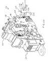
FIGS. 1 and 2 show acircuit breaker 20.Circuit breaker 20 generally includes a molded case having atop cover 22 attached to amid cover 24 coupled to abase 26. An opening28, formed generally centrally withintop cover 22, is positioned to mate with a corresponding mid cover opening30, which is accordingly aligned with opening28 whenmid cover 24 andtop cover 22 are coupled to one another.
In a 3-pole system (i.e., corresponding with three phases of current), threerotary cassettes base 26.Cassettes operating mechanism 38 via across pin 40.Operating mechanism 38 is positioned and configuredatop cassette 34, which is generally disposed intermediate tocassettes Operating mechanism 38 operates substantially as described herein and as described in U.S. patent application Ser. No. 09/196,706 entitled “Circuit Breaker Mechanism for a Rotary Contact Assembly”.
Atoggle handle 44 extends throughopenings cassettes operating mechanism 38 are described in more detail in U.S. patent application Ser. Nos. 09/087,038 and 09/384,908, both entitled “Rotary Contact Assembly For High Ampere Rated Circuit Breakers”, and U.S. patent application Ser. No. 09/384,495, entitled “Supplemental Trip Unit For Rotary Circuit Interrupters”.Cassettes opposing sidewalls 46,48.Sidewalls 46,48 have anarcuate slot 52 positioned and configured to receive and allow the motion ofcross pin 40 by action ofoperating mechanism 38.
FIGS. 3 and 4 show matable circuit draw outcircuit breaker compartment 25 andcircuit breaker 20. Eachcassette stabs 29. Draw outinterlock mechanism 250, which will be discussed in detail below, can be seen protruding from the back side ofcircuit breaker 20. To connectcircuit breaker 20 to a power distribution circuit, it is simply plugged intocompartment 25 so thatstabs 29 are inserted intocorresponding sockets 27. Whilestabs 29 andsockets 27 may be sufficient to mechanically supportcircuit breaker 20 incompartment 25, there may be supplemental mechanical connections, such as a screw or locking means (not shown) to provide a positive mechanical connection betweencircuit breaker 20 andcompartment 25. Additionally, mechanical means, such as a lever, jack screw, or release spring may be provided to aid in the removal ofcircuit breaker 20 fromcompartment 25 when desired.
Referring now to FIGS. 5,6, and7, an exemplaryrotary contact assembly 56 that is disposed within eachcassette operating mechanism 38, the components of which are described in greater detail further herein.Rotary contact assembly 56 includes a loadside contact strap 58 and lineside contact strap 62 for connection via stabs29 (FIG. 4) to a power source and a protected circuit (not shown), respectively. Loadside contact strap 58 includes astationary contact 64 and lineside contact strap 62 includes astationary contact 66.Rotary contact assembly 56 further includes amovable contact arm 68 having a set ofcontacts stationary contacts operating mechanism 38, whereintoggle handle 44 is oriented to the left (e.g., via a manual or mechanical force),contacts stationary contacts contact arm 68. It should be appreciated that whilerotary contact assembly 56 shows a contact arm having a pair of movable contacts, rotary contact assemblies wherein the contact arm has only a single movable contact is contemplated.
In the “on” position (FIG. 6) ofoperating mechanism 38, wherein toggle handle44 is oriented to the right as depicted in FIG. 3 (e.g., via a manual or mechanical force),contacts stationary contacts contact arm 68. In the “tripped” position (FIG. 7) toggle handle44 is oriented between the “on” position and the “off” position (typically by the release of mechanism springs withinoperating mechanism 38, described in greater detail herein). In this “tripped” position,contacts stationary contacts mechanism 38, thereby preventing current from flowing throughcontact arm 68. After operatingmechanism 38 is in the “tripped” position, it must ultimately be returned to the “on” position for operation. This is effectuated by applying a reset force to move toggle handle44 to a “reset” condition, which is beyond the “off” position (i.e., further to the left of the “off” position in FIG.3), and then back to the “on” position. This reset force must be high enough to overcome the mechanism springs, described herein.
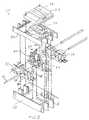
Referring now to FIGS. 8-10, the components ofoperating mechanism 38 will now be detailed. As viewed in FIGS. 8-10,operating mechanism 38 is in the “tripped” position.Operating mechanism 38 has operating mechanism side frames86 configured and positioned to straddlesidewalls 46,48 of cassette34 (FIG.2).
Toggle handle44 (FIG. 2) is rigidly interconnected with a drive member or handleyoke 88. Handleyoke 88 includes opposingside portions 89. Eachside portion 89 includes anextension 91 at to the top ofside portion 89, and aU-shaped portion 92 at the bottom portion of eachside portion 89.U-shaped portions 92 are rotatably positioned on a pair of bearingportions 94 protruding outwardly from side frames86.Bearing portions 94 are configured to retainhandle yoke 88, for example, with a securement washer. Handleyoke 88 further includes aroller pin 114 extending betweenextensions 91.
Handleyoke 88 is connected to a set of powerful mechanism springs96 by aspring anchor 98, which is generally supported within a pair ofopenings 102 inhandle yoke 88 and arranged through a complementary set ofopenings 104 on the top portion of mechanism springs96.
Referring to FIG. 11, the bottom portion of mechanism springs96 include a pair ofopenings 206. Adrive connector 235 operative couples mechanism springs96 to other operating mechanism components.Drive connector 235 comprises apin 202 disposed throughopenings 206, a set ofside tubes 203 arranged onpin 202 adjacent to the outside surface of the bottom portion of mechanism springs96, and acentral tube 204 arranged onpin 202 between the inside surfaces of the bottom portions of mechanism springs96.Central tube 204 includes step portions at each end, generally configured to maintain a suitable distance between mechanism springs96. Whiledrive connector 235 is detailed herein astubes pin 202, any means to connect the springs to the mechanism components are contemplated.
Referring to FIGS. 10,12, and13, a pair ofcradles 106 are disposed adjacent to side frames86 and pivot on apin 108 disposed through anopening 112 approximately at the end of eachcradle 106. Eachcradle 106 includes anedge surface 107, anarm 122 depending downwardly, and acradle latch surface 164 abovearm 122.Edge surface 107 is positioned generally at the portion ofcradle 106 in the range of contact withroller pin 114. Eachcradle 106 also includes astop surface 110 formed thereon. Arivet 116 disposed through anarcuate slot 118 within eachside frame 86, as best seen in FIGS. 7 and 10, guides the movement of eachcradle 106.Rivets 116 are disposed within anopening 117 on each cradle106 (FIG.13). Anarcuate slot 168 is positioned intermediate to opening112 andopening 117 on eachcradle 106. Anopening 172 is positioned aboveslot 168.
Referring back to FIGS. 8-10, aprimary latch 126 is positioned within side frames86.Primary latch 126 includes a pair of side portions128 (FIG.10). Eachside portion 128 includes abent leg 124 at the lower portion thereof.Side portions 128 are interconnected by acentral portion 132. A set ofextensions 166 depend outwardly fromcentral portion 132 positioned to align with cradle latch surfaces164.
Asecondary latch 138 is pivotally straddled over side frames86.Secondary latch 138 includes a set ofpins 142 disposed in a complementary pair ofnotches 144 on eachside frame 86.Secondary latch 138 includes a pair of secondarylatch trip tabs 146 that extend perpendicularly from operatingmechanism 38 as to allow an interface with the draw outinterlock mechanism 250, as will be further discussed below. Actuation by draw outinterlock mechanism 250 causessecondary latch 138 to release the engagement withprimary latch 126 thereby causingoperating mechanism 38 to move to the “tripped” position (e.g., as in FIG.5), described below.Secondary latch 138 includes a set of latch surfaces162, that align with primary latch surfaces158.
Referring to FIGS. 10,12 and13, a set ofupper links 174 are connected to cradles106.Upper links 174 generally have a right angle shape. Legs175 (in a substantially horizontal configuration in FIGS. 10 and 12) ofupper links 174 each have acam portion 171 that interfaces aroller 173 disposed between frames86. Legs176 (in a substantially vertical configuration in FIGS. 10 and 12) ofupper links 174 each have a pair ofopenings U-shaped portion 186 at the bottom end thereof.Opening 184 is intermediate to opening182 andU-shaped portion 186.Upper links 174 connect to cradle106 via a securement structure such as arivet pin 188 disposed throughopening 172 andopening 182, and a securement structure such as arivet pin 191 disposed throughslot 168 andopening 184. Rivet pins188,191 both attach to aconnector 193 to secure eachupper link 174 to eachcradle 106. Eachpin portions portions upper link 174 and eachcradle 106. The space serves to reduce or eliminate friction betweenupper link 174 andcradle 106 during any operating mechanism motion, and also to spread force loading betweencradles 106 andupper links 174.
Referring to FIGS. 17-19, eachlower link 194 is interconnected with a crank208 via apivotal rivet 210 disposed through anopening 199 inlower link 194 and anopening 209 incrank 208. Each crank208 pivots about acenter 211.Crank 208 has anopening 212 where cross pin40 (FIG. 2) passes through intoarcuate slot 52 ofcassettes
Aspacer 234 is included on eachpivotal rivet 210 between eachlower link 194 and crank208.Spacers 234 spread the force loading fromlower links 194 tocranks 208 over a wider base, and also reduces friction betweenlower links 194 and cranks208, thereby minimizing the likelihood of binding (e.g., when operatingmechanism 38 is changed from the “off” position to the “on” position manually or mechanically, or when operatingmechanism 38 is changed from the “on” position to the “tripped” position of the release ofprimary latch 126 and secondary latch138).
Referring back to FIGS. 5-7, the movement ofoperating mechanism 38 relative torotary contact assembly 56 will be detailed.
Referring to FIG. 5, in the “off” position toggle handle44 is rotated to the left and mechanism springs96,lower link 194 and crank208 are positioned to maintaincontact arm 68 so thatmovable contacts stationary contacts Operating mechanism 38 becomes set in the “off” position after a reset force properly alignsprimary latch 126,secondary latch 138 and cradle106 (e.g., after operatingmechanism 38 has been tripped) and is released. Thus, when the reset force is released,extensions 166 ofprimary latch 126 rest upon cradle latch surfaces164, and primary latch surfaces158 rest upon secondary latch surfaces162. Eachupper link 174 andlower link 194 are bent with respect to eachside tube 203. The line of forces generated by mechanism springs96 (i.e., betweenspring anchor 98 and pin202) is to the left of bearing portion94 (as oriented in FIGS.3-5).Cam surface 171 ofupper link 174 is out of contact withroller 173.
Referring now to FIG. 6, a manual closing force was applied to togglehandle 44 to move it from the “off” position (i.e., FIG. 5) to the “on” position (i.e., to the right as oriented in FIG.6). While the closing force is applied,upper links 174 rotate withinarcuate slots 168 ofcradles 106 aboutpins 188, andlower link 194 is driven to the right under bias of themechanism spring 96. Raisedportions 189 and192 (FIG. 12 and 13) maintain a suitable space between the surfaces ofupper links 174 and cradles106 to prevent friction therebetween, which would increase the required set operatingmechanism 38 from “off” to “on”. Furthermore,side walls 197 of bearing washers196 (FIGS. 14-16) maintain the position ofupper link 174 onside tube 203 and minimize likelihood of binding (e.g., so as to preventupper link 174 from shifting intosprings 96 or into lower link194).
To alignvertical leg 176 andlower link 194, the line of force generated by mechanism springs96 is shifted to the right of bearingportion 94, which causesrivet 210 couplinglower link 194 and crank208 to be driven downwardly and to rotate crank208 clockwise aboutcenter 211. This, in turn, drivescross pin 40 to the upper end of arcuate slot214. Therefore, the forces transmitted throughcross pin 40 torotary contact assembly 56 via opening82 drivemovable contacts stationary contacts spacer 234 on pivotal rivet210 (FIGS.11 and17-19) maintain the appropriate distance betweenlower links 194 and cranks208 to prevent interference or friction therebetween or from side frames86.
The interface betweenprimary latch 126 and secondary latch138 (i.e., betweenprimary latch surface 158 and secondary latch surface162), and betweencradles 106 and primary latch126 (i.e., betweenextensions 166 and cradle latch surfaces164) is not affected when a force is applied to togglehandle 44 to change from the “off” position to the “on” position.
Referring now to FIG. 5, in the “tripped” condition, secondarylatch trip tab 146 has been displaced, e.g., by the draw out interlock mechanism, described in detail below, and the interface betweenprimary latch 126 andsecondary latch 138 is released.Extensions 166 ofprimary latch 126 are disengaged from cradle latch surfaces164, and cradles106 is rotated clockwise about pin108 (i.e., motion guided byrivet 116 in arcuate slot118). The movement ofcradle 106 transmits a force viarivets upper link 174 havingcam surface 171. After a short predetermined rotation,cam surface 171 ofupper link 174contacts roller 173. The force resulting from the contact ofcam surface 171 onroller 173 causesupper link 174 andlower link 194 to buckle and allows mechanism springs96 to pulllower link 194 viapin 202. In turn,lower link 194 transmits a force to crank208 (i.e., via rivet210) causing crank208 to rotate counter clockwise aboutcenter 211 and drivecross pin 40 to the lower portion of arcuate slot214. The forces transmitted throughcross pin 40 torotary contact assembly 56 via opening82 causemovable contacts stationary contacts
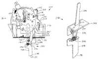
Referring now to FIGS. 20-22, the draw outinterlock mechanism 250 will be described in detail.Pivot pin 258 is riveted to aside frame 86 ofoperating mechanism 38. Draw outtrip arm 260 includes afirst extension 268 at an upper end, a draw outtrip tab 266 formed on asecond extension 265 on a lower end, and an aperture264 (FIG. 20) that is placed overpin 258. Draw outtrip arm 260 is pivotally locked into place withbushing 261 by forcingretainer clip 262 over a circumferential groove formed intopin 258 so that it is free to rotate onpin 258 betweenbushing 261 and a shoulder formed intopin 258. Areturn spring 270 is connected between notch256 formed intosidewall 86 and asmall aperture 266 formed in draw outtrip arm 260.
Shown in FIG. 21 isinterlock activating assembly 280 attached to base26 of circuit breaker20 (FIGS.1 and4).Interlock activating assembly 280 is shown in further detail in FIG. 22, and comprises a mountingbracket 282, anextended arm 284 which pivots aboutpin 286, acamming arm 288 which also pivots onpin 286. In one embodiment (not shown),extended arm 284 andcamming arm 288 are fixed to one another or formed as a unitary structure. In the embodiment shown, take upspring 292 biases extendedarm 284 againststop 294 ofcamming arm 288, as best seen in FIG.21.Camming arm 288 has acam surface 290.Interlock activating assembly 280 is installed ontobase 26 ofcircuit breaker 20 withextended arm 284 extending throughaperture 283 formed intobase 26. It will be appreciated that installation of draw outtrip mechanism 250 onto a fully-assembledoperating mechanism 38 can be accomplished in only a few steps and does not require any disassembly of theoperating mechanism 38.
FIG. 21 clearly shows the operation of draw outtrip mechanism 250. Draw outtrip mechanism 250 causes draw outcircuit breaker 20 to trip when inserted or removed fromcompartment 25.Compartment 25 includes acamming surface 33 which may be a pin, roller, or other surface such as shown in FIG.3. When draw outcircuit breaker 20 is installed into compartment25 (FIGS. 3 and 4)camming surface 33 will contactcam surface 290 causing cammingarm 288 to rotate in a clockwise direction as seen in FIG.21. When cammingarm 288 rotates clockwise, stop294 moves to the right, allowingextended arm 284 to rotate clockwise under influence of take upspring 292, which is under tension.
Whencircuit breaker 20 is fully installed intocompartment 25,camming pin 33 is in the position shown in phantom in FIG.21.Notch 296 formed intocamming arm 288, allows cammingarm 288 andextended arm 284 to rotate back to a natural position under the influence ofreturn spring 270. This position allowssecondary latch 138 to be released, permitting the moving and stationary contacts in draw outcircuit breaker 20 to be closed by movinghandle yoke 88 to the “on” position shown in FIG.6. It will be appreciated that a similar tripping occurs due to the interaction ofcamming surface 33 andcamming arm 288 whencircuit breaker 20 is removed fromcompartment 25 as whencircuit breaker 20 is inserted intocompartment 25.
While the invention has been described with reference to a preferred embodiment, it will be understood by those skilled in the art that various changes may be made and equivalents may be substituted for elements thereof without departing from the scope of the invention. In addition, many modifications may be made to adapt a particular situation or material to the teachings of the invention without departing from the essential scope thereof. Therefore, it is intended that the invention not be limited to the particular embodiment disclosed as the best mode contemplated for carrying out this invention, but that the invention will include all embodiments falling within the scope of the appended claims.
Claims (13)
1. A draw out interlock mechanism for a draw out circuit breaker, the draw out interlock mechanism comprising: a draw out trip arm coupled within said draw out circuit breaker so that said draw out trip arm is pivotable with respect to said draw out circuit breaker, said draw out trip arm comprising:
a first extension on a first end of said draw out trip arm for interacting with a trip latch of said operating mechanism, and
a second extension formed on a second end of said draw out trip arm; and
an interlock activating assembly, said interlock activating assembly comprising:
a mounting bracket for attaching said interlock activating assembly to said draw out circuit breaker, and
an extended arm and a camming arm, said extended arm and said camming arm pivotally attached to a pin that is mounted to the mounting bracket, said extended arm extending through an aperture in said draw out circuit breaker with an end thereof proximate to said second extension of said draw out trip arm when said mounting bracket is installed on said draw out circuit breaker;
wherein said camming arm interacts with a camming surface attached to a compartment such that when said draw out circuit breaker is inserted into said compartment, said camming arm and said extended arm separately rotate in a first direction, said extended arm interacting with said second extension of said draw out trip arm causing said draw out trip arm to rotate in a second direction, causing said first extension to interact with said trip latch causing said draw out circuit breaker to trip; and
wherein said extended arm and said camming arm are connected by a take up spring that allows over-rotation of said camming arm with respect to said extended arm.
2. The draw out interlock mechanism ofclaim 1 wherein said draw out trip arm further comprises a return spring biasing said first extension away from said trip latch.
3. The draw out interlock mechanism ofclaim 1 wherein said camming arm includes a first surface and said camming surface comprises a pin mounted in said compartment, wherein as said draw out circuit breaker is inserted, said first surface rides against said pin, forcing said camming arm to rotate in said first direction.
4. The draw out interlock mechanism ofclaim 3 wherein said camming arm further includes a second surface, configured such that as said draw out circuit breaker is inserted, said first surface forces said camming arm to rotate in said first direction, then said second surface allows said camming arm to rotate back in said second direction so that when said draw out circuit breaker is fully inserted in said compartment, said draw out circuit breaker is allowed to be reset.
5. The draw out interlock mechanism ofclaim 1 wherein said camming arm and said camming surface are configured to interact with each other so that as said draw out circuit breaker is inserted, said camming arm rotates in said first direction, then said camming arm rotates back in said second direction so that when said draw out circuit breaker is fully inserted in said compartment, said draw out circuit breaker is allowed to be reset.
6. The draw out interlock mechanism ofclaim 1 wherein said draw out interlock mechanism is attached to a side plate of a circuit breaker operating mechanism.
7. A draw out circuit breaker comprising:
a movable contact and a fixed contact electrically connected in series between a load side stab and a line side stab for each pole of said draw out circuit breaker;
an operating mechanism for causing said movable and fixed contacts to open and close, said operating mechanism including:
an “off” state wherein said movable contact and said fixed contact are open,
an “on” state wherein said movable contact and said fixed contact are closed, and
a “tripped” state wherein said movable contact and said fixed contact are open;
said operating mechanism further comprising a trip latch for switching said operating mechanism from said on state to said tripped state when said trip latch is moved; and
a draw out interlock mechanism comprising:
a draw out trip arm pivotally attached within said circuit breaker, said draw out trip arm comprising:
a first extension on a first end of said draw out trip arm for interacting with said trip latch, and
a second extension on a second end of said draw out trip arm; and
an interlock activating assembly, said interlock activating assembly comprising:
an extended arm,
a camming arm, and
a support bracket mounted to the draw out circuit breaker with said extended arm extending through an aperture in said draw out circuit breaker with an end of said extended arm proximate said second extension of said draw out trip arm;
wherein said extended arm and said camming arm are pivotally attached to a pin mounted to the support bracket, said camming arm interacts with a camming surface attached to a compartment such that when and said draw out circuit breaker is inserted into said compartment, said camming arm and said extended arm rotate in a first direction, said extended arm interacts with said second extension of said draw out trip arm causing said draw out trip arm to rotate in a second direction, in turn causing said first extension of said draw out trip arm to interact with said trip latch causing said draw out circuit breaker to trip, separating said movable and fixed contacts; and
wherein said extended arm and said camming arm are connected by a take up spring that allows over-rotation of said camming arm with respect to said extended arm.
8. The draw out circuit breaker ofclaim 7 wherein said draw out trip arm further comprises a return spring biasing said first extension away from said trip latch.
9. The draw out circuit breaker ofclaim 7 wherein said camming arm includes a first surface and said camming surface comprises a pin mounted in said compartment, wherein as said draw out circuit breaker is inserted, said first surface rides against said pin, forcing said camming arm to rotate in said first direction.
10. The draw out circuit breaker ofclaim 9 wherein said camming arm further includes a second surface, configured such that as said draw out circuit breaker is inserted, said first surface forces said camming arm to rotate in said first direction, then said second surface allows said camming arm to rotate back in said second direction so that when said draw out circuit breaker is fully inserted in said compartment, said draw out circuit breaker is allowed to be reset and said contacts to be closed.
11. The draw out circuit breaker ofclaim 7 wherein said camming arm and said camming surface are configured to interact with each other so that as said draw out circuit breaker is inserted, said camming arm rotates in said first direction, then said camming arm rotates back in said second direction so that when said draw out circuit breaker is fully inserted in said compartment, said draw out circuit breaker is allowed to be reset and said contacts to be closed.
12. The draw out circuit breaker ofclaim 7 wherein said draw out interlock mechanism is attached to a side plate of a circuit breaker operating mechanism.
13. A draw out circuit breaker comprising:
a movable contact and a fixed contact electrically connected in series between a load side stab and a line side stab for each pole of said draw out circuit breaker;
an operating mechanism for causing said movable and fixed contacts to open and close; and
a draw out interlock mechanism comprising:
a draw out trip arm pivotally attached to said operating mechanism, said draw out trip arm comprising:
a first extension on a first end of said draw out trip arm for interacting with said trip latch, and
a second extension on a second end of said draw out trip arm; and
an interlock activating assembly, said interlock activating assembly comprising:
an extended arm,
a camming arm, and
a support bracket mounted to the draw out circuit breaker with said extended arm extending through an aperture in said draw out circuit breaker with an end of said extended arm proximate said second extension of said draw out trip arm; and
wherein said extended arm and said camming arm are pivotally attached to a pin mounted to the support bracket, said camming arm interacts with a camming surface attached to a compartment such that when and said draw out circuit breaker is inserted into said compartment, said camming arm and said extended arm rotate in a first direction, said extended arm interacts with said second extension of said draw out trip arm causing said draw out trip arm to rotate in a second direction, in turn causing said first extension of said draw out trip arm to interact with said trip latch causing said draw out circuit breaker to trip, separating said movable and fixed contacts; and
wherein said extended arm and said camming arm are connected by a take up spring that allows over-rotation of said camming arm with respect to said extended arm.
Priority Applications (2)
| Application Number | Priority Date | Filing Date | Title |
|---|---|---|---|
| US09/687,041US6400245B1 (en) | 2000-10-13 | 2000-10-13 | Draw out interlock for circuit breakers |
| IT2001MI002109AITMI20012109A1 (en) | 2000-10-13 | 2001-10-12 | EXTRACTION INTERLOCK FOR ELECTRIC SWITCHES |
Applications Claiming Priority (1)
| Application Number | Priority Date | Filing Date | Title |
|---|---|---|---|
| US09/687,041US6400245B1 (en) | 2000-10-13 | 2000-10-13 | Draw out interlock for circuit breakers |
Publications (1)
| Publication Number | Publication Date |
|---|---|
| US6400245B1true US6400245B1 (en) | 2002-06-04 |
Family
ID=24758764
Family Applications (1)
| Application Number | Title | Priority Date | Filing Date |
|---|---|---|---|
| US09/687,041Expired - LifetimeUS6400245B1 (en) | 2000-10-13 | 2000-10-13 | Draw out interlock for circuit breakers |
Country Status (2)
| Country | Link |
|---|---|
| US (1) | US6400245B1 (en) |
| IT (1) | ITMI20012109A1 (en) |
Cited By (12)
| Publication number | Priority date | Publication date | Assignee | Title |
|---|---|---|---|---|
| US6617533B1 (en) | 2002-09-20 | 2003-09-09 | Siemens Energy & Automation, Inc. | Interlock for a circuit breaker |
| US6693502B2 (en)* | 2000-12-01 | 2004-02-17 | Lg Industrial Systems Co., Ltd. | Air circuit breaker |
| US20060071750A1 (en)* | 2004-10-01 | 2006-04-06 | Marks Douglas C | Support structure for a circuit interrupter latch and circuit breaker employing the same |
| US7057123B1 (en) | 2005-02-14 | 2006-06-06 | Eaton Corporation | Safety interlock for circuit breaker housing assembly and extraction device |
| US20070085639A1 (en)* | 2005-10-19 | 2007-04-19 | Eaton Corporation | Circuit breaker intermediate latch stop |
| US8350168B2 (en) | 2010-06-30 | 2013-01-08 | Schneider Electric USA, Inc. | Quad break modular circuit breaker interrupter |
| US20140375400A1 (en)* | 2013-06-20 | 2014-12-25 | Schneider Electric Industries Sas | Trip unit and method for producing one such trip device |
| US20150035628A1 (en)* | 2012-03-12 | 2015-02-05 | Siemens Aktiengesellschaft | Circuit breaker trip blocking apparatus, systems, and methods of operation |
| US9153948B2 (en) | 2013-02-11 | 2015-10-06 | General Electric Company | System and method for actuation of power panel |
| US20170194123A1 (en)* | 2014-05-22 | 2017-07-06 | Eaton Industries (Austria) Gmbh | Shifting device |
| US20170229261A1 (en)* | 2016-02-10 | 2017-08-10 | Abb S.P.A. | Switching device for lv electric installations |
| US10984974B2 (en)* | 2018-12-20 | 2021-04-20 | Schneider Electric USA, Inc. | Line side power, double break, switch neutral electronic circuit breaker |
Citations (217)
| Publication number | Priority date | Publication date | Assignee | Title |
|---|---|---|---|---|
| US2340682A (en) | 1942-05-06 | 1944-02-01 | Gen Electric | Electric contact element |
| US2719203A (en) | 1952-05-02 | 1955-09-27 | Westinghouse Electric Corp | Circuit breakers |
| US2937254A (en) | 1957-02-05 | 1960-05-17 | Gen Electric | Panelboard unit |
| US3158717A (en) | 1962-07-18 | 1964-11-24 | Gen Electric | Electric circuit breaker including stop means for limiting movement of a toggle linkage |
| US3162739A (en) | 1962-06-25 | 1964-12-22 | Gen Electric | Electric circuit breaker with improved trip means |
| US3197582A (en) | 1962-07-30 | 1965-07-27 | Fed Pacific Electric Co | Enclosed circuit interrupter |
| DE1227978B (en) | 1963-10-04 | 1966-11-03 | Licentia Gmbh | Electrical switchgear, in particular contactor |
| US3307002A (en) | 1965-02-04 | 1967-02-28 | Texas Instruments Inc | Multipole circuit breaker |
| US3517356A (en) | 1967-07-24 | 1970-06-23 | Terasaki Denki Sangyo Kk | Circuit interrupter |
| US3631369A (en) | 1970-04-27 | 1971-12-28 | Ite Imperial Corp | Blowoff means for circuit breaker latch |
| US3803455A (en) | 1973-01-02 | 1974-04-09 | Gen Electric | Electric circuit breaker static trip unit with thermal override |
| BE819008A (en) | 1973-08-20 | 1974-12-16 | DIFFERENTIAL TRIGGER | |
| US3883781A (en) | 1973-09-06 | 1975-05-13 | Westinghouse Electric Corp | Remote controlled circuit interrupter |
| US4129762A (en) | 1976-07-30 | 1978-12-12 | Societe Anonyme Dite: Unelec | Circuit-breaker operating mechanism |
| US4144513A (en) | 1977-08-18 | 1979-03-13 | Gould Inc. | Anti-rebound latch for current limiting switches |
| US4158119A (en) | 1977-07-20 | 1979-06-12 | Gould Inc. | Means for breaking welds formed between circuit breaker contacts |
| US4165453A (en) | 1976-08-09 | 1979-08-21 | Societe Anonyme Dite: Unelec | Switch with device to interlock the switch control if the contacts stick |
| US4166988A (en) | 1978-04-19 | 1979-09-04 | General Electric Company | Compact three-pole circuit breaker |
| FR2410353B1 (en) | 1977-11-28 | 1980-08-22 | Merlin Gerin | |
| US4220934A (en) | 1978-10-16 | 1980-09-02 | Westinghouse Electric Corp. | Current limiting circuit breaker with integral magnetic drive device housing and contact arm stop |
| US4255732A (en) | 1978-10-16 | 1981-03-10 | Westinghouse Electric Corp. | Current limiting circuit breaker |
| US4259651A (en) | 1978-10-16 | 1981-03-31 | Westinghouse Electric Corp. | Current limiting circuit interrupter with improved operating mechanism |
| US4263492A (en) | 1979-09-21 | 1981-04-21 | Westinghouse Electric Corp. | Circuit breaker with anti-bounce mechanism |
| US4276527A (en) | 1978-06-23 | 1981-06-30 | Merlin Gerin | Multipole electrical circuit breaker with improved interchangeable trip units |
| US4297663A (en) | 1979-10-26 | 1981-10-27 | General Electric Company | Circuit breaker accessories packaged in a standardized molded case |
| US4301342A (en) | 1980-06-23 | 1981-11-17 | General Electric Company | Circuit breaker condition indicator apparatus |
| US4317160A (en) | 1980-07-31 | 1982-02-23 | General Electric Company | Electrical switchboard having improved drawout apparatus |
| US4360852A (en) | 1981-04-01 | 1982-11-23 | Allis-Chalmers Corporation | Overcurrent and overtemperature protective circuit for power transistor system |
| US4368444A (en) | 1980-08-29 | 1983-01-11 | Siemens Aktiengesellschaft | Low-voltage protective circuit breaker with locking lever |
| US4375021A (en) | 1980-01-31 | 1983-02-22 | General Electric Company | Rapid electric-arc extinguishing assembly in circuit-breaking devices such as electric circuit breakers |
| US4375022A (en) | 1979-03-23 | 1983-02-22 | Alsthom-Unelec | Circuit breaker fitted with a device for indicating a short circuit |
| US4376270A (en) | 1980-09-15 | 1983-03-08 | Siemens Aktiengesellschaft | Circuit breaker |
| US4383146A (en) | 1980-03-12 | 1983-05-10 | Merlin Gerin | Four-pole low voltage circuit breaker |
| US4392036A (en) | 1980-08-29 | 1983-07-05 | Siemens Aktiengesellschaft | Low-voltage protective circuit breaker with a forked locking lever |
| US4393283A (en) | 1980-04-10 | 1983-07-12 | Hosiden Electronics Co., Ltd. | Jack with plug actuated slide switch |
| US4401872A (en) | 1981-05-18 | 1983-08-30 | Merlin Gerin | Operating mechanism of a low voltage electric circuit breaker |
| US4409573A (en) | 1981-04-23 | 1983-10-11 | Siemens-Allis, Inc. | Electromagnetically actuated anti-rebound latch |
| FR2512582B1 (en) | 1981-09-10 | 1983-10-28 | Merlin Gerin | |
| EP0061092B1 (en) | 1981-03-20 | 1983-12-21 | BASF Aktiengesellschaft | Electrophotographic recording material |
| US4435690A (en) | 1982-04-26 | 1984-03-06 | Rte Corporation | Primary circuit breaker |
| US4467297A (en) | 1981-05-07 | 1984-08-21 | Merlin Gerin | Multi-pole circuit breaker with interchangeable magneto-thermal tripping unit |
| US4468645A (en) | 1981-10-05 | 1984-08-28 | Merlin Gerin | Multipole circuit breaker with removable trip unit |
| EP0117094A1 (en) | 1983-02-18 | 1984-08-29 | Heinemann Electric Company | A circuit breaker comprising parallel connected sections |
| US4470027A (en) | 1982-07-16 | 1984-09-04 | Eaton Corporation | Molded case circuit breaker with improved high fault current interruption capability |
| US4479143A (en) | 1980-12-16 | 1984-10-23 | Sharp Kabushiki Kaisha | Color imaging array and color imaging device |
| US4488133A (en) | 1983-03-28 | 1984-12-11 | Siemens-Allis, Inc. | Contact assembly including spring loaded cam follower overcenter means |
| US4541032A (en) | 1980-10-21 | 1985-09-10 | B/K Patent Development Company, Inc. | Modular electrical shunts for integrated circuit applications |
| US4546224A (en) | 1982-10-07 | 1985-10-08 | Sace S.P.A. Costruzioni Elettromeccaniche | Electric switch in which the control lever travel is arrested if the contacts become welded together |
| US4550360A (en) | 1984-05-21 | 1985-10-29 | General Electric Company | Circuit breaker static trip unit having automatic circuit trimming |
| US4562419A (en) | 1983-12-22 | 1985-12-31 | Siemens Aktiengesellschaft | Electrodynamically opening contact system |
| FR2553943B1 (en) | 1983-10-24 | 1986-04-11 | Merlin Gerin | RESIDUAL DIFFERENTIAL DEVICE PROVIDED WITH A DEVICE FOR MONITORING THE ELECTRONIC POWER SOURCE |
| US4589052A (en) | 1984-07-17 | 1986-05-13 | General Electric Company | Digital I2 T pickup, time bands and timing control circuits for static trip circuit breakers |
| US4595812A (en) | 1983-09-21 | 1986-06-17 | Mitsubishi Denki Kabushiki Kaisha | Circuit interrupter with detachable optional accessories |
| US4611187A (en) | 1984-02-15 | 1986-09-09 | General Electric Company | Circuit breaker contact arm latch mechanism for eliminating contact bounce |
| US4612430A (en) | 1984-12-21 | 1986-09-16 | Square D Company | Anti-rebound latch |
| US4616198A (en) | 1984-08-14 | 1986-10-07 | General Electric Company | Contact arrangement for a current limiting circuit breaker |
| US4622444A (en) | 1984-07-20 | 1986-11-11 | Fuji Electric Co., Ltd. | Circuit breaker housing and attachment box |
| US4631625A (en) | 1984-09-27 | 1986-12-23 | Siemens Energy & Automation, Inc. | Microprocessor controlled circuit breaker trip unit |
| US4642431A (en) | 1985-07-18 | 1987-02-10 | Westinghouse Electric Corp. | Molded case circuit breaker with a movable electrical contact positioned by a camming spring loaded clip |
| US4644438A (en) | 1983-06-03 | 1987-02-17 | Merlin Gerin | Current-limiting circuit breaker having a selective solid state trip unit |
| US4649247A (en) | 1984-08-23 | 1987-03-10 | Siemens Aktiengesellschaft | Contact assembly for low-voltage circuit breakers with a two-arm contact lever |
| US4658322A (en) | 1982-04-29 | 1987-04-14 | The United States Of America As Represented By The Secretary Of The Navy | Arcing fault detector |
| US4672501A (en) | 1984-06-29 | 1987-06-09 | General Electric Company | Circuit breaker and protective relay unit |
| US4675481A (en) | 1986-10-09 | 1987-06-23 | General Electric Company | Compact electric safety switch |
| US4682264A (en) | 1985-02-25 | 1987-07-21 | Merlin Gerin | Circuit breaker with digital solid-state trip unit fitted with a calibration circuit |
| DE3047360C2 (en) | 1980-12-16 | 1987-08-20 | Karl Pfisterer Elektrotechnische Spezialartikel Gmbh & Co Kg, 7000 Stuttgart | Switching strip |
| US4689712A (en) | 1985-02-25 | 1987-08-25 | Merlin Gerin S.A. | Circuit breaker with solid-state trip unit with a digital processing system shunted by an analog processing system |
| EP0140761B1 (en) | 1983-10-21 | 1987-09-09 | Merlin Gerin | Operating mechanism for a low-voltage multi-pole circuit breaker |
| US4694373A (en) | 1985-02-25 | 1987-09-15 | Merlin Gerin | Circuit breaker with digital solid-state trip unit with optional functions |
| US4710845A (en) | 1985-02-25 | 1987-12-01 | Merlin Gerin S.A. | Circuit breaker with solid-state trip unit with sampling and latching at the last signal peak |
| US4717985A (en) | 1985-02-25 | 1988-01-05 | Merlin Gerin S.A. | Circuit breaker with digitized solid-state trip unit with inverse time tripping function |
| US4728757A (en) | 1985-02-01 | 1988-03-01 | Square D Company | Interlock scheme for drawout high amperage multi-pole circuit breaker |
| FR2592998B1 (en) | 1986-01-10 | 1988-03-18 | Merlin Gerin | TEST CIRCUIT FOR AN ELECTRONIC TRIGGER OF A DIFFERENTIAL CIRCUIT BREAKER. |
| US4733211A (en) | 1987-01-13 | 1988-03-22 | General Electric Company | Molded case circuit breaker crossbar assembly |
| US4733321A (en) | 1986-04-30 | 1988-03-22 | Merlin Gerin | Solid-state instantaneous trip device for a current limiting circuit breaker |
| US4764650A (en) | 1985-10-31 | 1988-08-16 | Merlin Gerin | Molded case circuit breaker with removable arc chutes and disengageable transmission system between the operating mechanism and the poles |
| US4768007A (en) | 1986-02-28 | 1988-08-30 | Merlin Gerin | Current breaking device with solid-state switch and built-in protective circuit breaker |
| US4780786A (en) | 1986-08-08 | 1988-10-25 | Merlin Gerin | Solid-state trip unit of an electrical circuit breaker with contact wear indicator |
| US4831221A (en) | 1987-12-16 | 1989-05-16 | General Electric Company | Molded case circuit breaker auxiliary switch unit |
| US4870531A (en) | 1988-08-15 | 1989-09-26 | General Electric Company | Circuit breaker with removable display and keypad |
| US4884047A (en) | 1987-12-10 | 1989-11-28 | Merlin Gerin | High rating multipole circuit breaker formed by two adjoined molded cases |
| US4884164A (en) | 1989-02-01 | 1989-11-28 | General Electric Company | Molded case electronic circuit interrupter |
| US4883931A (en) | 1987-06-18 | 1989-11-28 | Merlin Gerin | High pressure arc extinguishing chamber |
| US4900882A (en) | 1987-07-02 | 1990-02-13 | Merlin Gerin | Rotating arc and expansion circuit breaker |
| US4910485A (en) | 1987-10-26 | 1990-03-20 | Merlin Gerin | Multiple circuit breaker with double break rotary contact |
| US4914541A (en) | 1988-01-28 | 1990-04-03 | Merlin Gerin | Solid-state trip device comprising an instantaneous tripping circuit independent from the supply voltage |
| US4916421A (en) | 1987-10-01 | 1990-04-10 | General Electric Company | Contact arrangement for a current limiting circuit breaker |
| US4916420A (en) | 1987-06-09 | 1990-04-10 | Merlin Gerin | Operating mechanism of a miniature electrical circuit breaker |
| US4926282A (en) | 1987-06-12 | 1990-05-15 | Bicc Public Limited Company | Electric circuit breaking apparatus |
| DE3802184C2 (en) | 1988-01-26 | 1990-05-17 | Licentia Patent-Verwaltungs-Gmbh, 6000 Frankfurt, De | |
| US4935590A (en) | 1988-03-01 | 1990-06-19 | Merlin Gerin | Gas-blast circuit breaker |
| US4937706A (en) | 1987-12-10 | 1990-06-26 | Merlin Gerin | Ground fault current protective device |
| DE3843277A1 (en) | 1988-12-22 | 1990-06-28 | Bosch Gmbh Robert | Power output stage for electromagnetic loads |
| US4939492A (en) | 1988-01-28 | 1990-07-03 | Merlin Gerin | Electromagnetic trip device with tripping threshold adjustment |
| US4943691A (en) | 1988-06-10 | 1990-07-24 | Merlin Gerin | Low-voltage limiting circuit breaker with leaktight extinguishing chamber |
| US4943888A (en) | 1989-07-10 | 1990-07-24 | General Electric Company | Electronic circuit breaker using digital circuitry having instantaneous trip capability |
| US4950855A (en) | 1987-11-04 | 1990-08-21 | Merlin Gerin | Self-expansion electrical circuit breaker with variable extinguishing chamber volume |
| US4950848A (en) | 1989-09-22 | 1990-08-21 | Westinghouse Electric Corp. | Adjustable circuit breaker with draw out interlock |
| US4951019A (en) | 1989-03-30 | 1990-08-21 | Westinghouse Electric Corp. | Electrical circuit breaker operating handle block |
| US4952897A (en) | 1987-09-25 | 1990-08-28 | Merlin Gerin | Limiting circuit breaker |
| US4958135A (en) | 1987-12-10 | 1990-09-18 | Merlin Gerin | High rating molded case multipole circuit breaker |
| US4965543A (en) | 1988-11-16 | 1990-10-23 | Merin Gerin | Magnetic trip device with wide tripping threshold setting range |
| EP0394922A1 (en) | 1989-04-28 | 1990-10-31 | Asea Brown Boveri Ab | Contact arrangement for electric switching devices |
| GB2233155A (en) | 1989-04-27 | 1991-01-02 | Delta Circuits Protection | Electric circuit breaker |
| US4983788A (en) | 1988-06-23 | 1991-01-08 | Cge Compagnia Generale Electtromeccanica S.P.A. | Electric switch mechanism for relays and contactors |
| US5001313A (en) | 1989-02-27 | 1991-03-19 | Merlin Gerin | Rotating arc circuit breaker with centrifugal extinguishing gas effect |
| US5004878A (en) | 1989-03-30 | 1991-04-02 | General Electric Company | Molded case circuit breaker movable contact arm arrangement |
| EP0224396B1 (en) | 1985-10-31 | 1991-06-05 | Merlin Gerin | Control mechanism for a low-tension electric circuit breaker |
| US5029301A (en) | 1989-06-26 | 1991-07-02 | Merlin Gerin | Limiting circuit breaker equipped with an electromagnetic effect contact fall delay device |
| US5057655A (en) | 1989-03-17 | 1991-10-15 | Merlin Gerin | Electrical circuit breaker with self-extinguishing expansion and insulating gas |
| EP0283358B1 (en) | 1987-03-09 | 1991-11-27 | Merlin Gerin | Static trip unit comprising a circuit for detecting the residual current |
| US5077627A (en) | 1989-05-03 | 1991-12-31 | Merlin Gerin | Solid-state trip device for a protective circuit breaker of a three-phase mains system, enabling the type of fault to be detected |
| US5083081A (en) | 1990-03-01 | 1992-01-21 | Merlin Gerin | Current sensor for an electronic trip device |
| EP0264313B1 (en) | 1986-09-23 | 1992-01-29 | Merlin Gerin | Electric differential-protection apparatus with a test circuit |
| US5095183A (en) | 1989-01-17 | 1992-03-10 | Merlin Gerin | Gas-blast electrical circuit breaker |
| US5103198A (en) | 1990-05-04 | 1992-04-07 | Merlin Gerin | Instantaneous trip device of a circuit breaker |
| EP0313422B1 (en) | 1987-10-09 | 1992-04-22 | Merlin Gerin | Static tripping device for a circuit breaker in a cast case |
| US5115371A (en) | 1989-09-13 | 1992-05-19 | Merlin Gerin | Circuit breaker comprising an electronic trip device |
| EP0239460B1 (en) | 1986-03-26 | 1992-06-03 | Merlin Gerin | Electric switch having an ameliorated dielectric strength |
| US5120921A (en) | 1990-09-27 | 1992-06-09 | Siemens Energy & Automation, Inc. | Circuit breaker including improved handle indication of contact position |
| US5132865A (en) | 1989-09-13 | 1992-07-21 | Merlin Gerin | Ultra high-speed circuit breaker with galvanic isolation |
| US5138121A (en) | 1989-08-16 | 1992-08-11 | Siemens Aktiengesellschaft | Auxiliary contact mounting block |
| US5140115A (en) | 1991-02-25 | 1992-08-18 | General Electric Company | Circuit breaker contacts condition indicator |
| US5153802A (en) | 1990-06-12 | 1992-10-06 | Merlin Gerin | Static switch |
| US5155315A (en) | 1989-12-11 | 1992-10-13 | Merlin Gerin | Hybrid medium voltage circuit breaker |
| EP0291374B1 (en) | 1987-05-11 | 1992-10-21 | Merlin Gerin | Trip bar for a multipole breaker block associated with an auxiliary trip block |
| EP0295155B1 (en) | 1987-05-11 | 1992-10-28 | Merlin Gerin | Modular breaker with an auxiliary tripping block associated with a multipole breaker block |
| US5166483A (en) | 1990-06-14 | 1992-11-24 | Merlin Gerin | Electrical circuit breaker with rotating arc and self-extinguishing expansion |
| US5172087A (en) | 1992-01-31 | 1992-12-15 | General Electric Company | Handle connector for multi-pole circuit breaker |
| EP0313106B1 (en) | 1987-03-12 | 1992-12-16 | Merlin Gerin Limited | Electrical switchgear |
| EP0283189B1 (en) | 1987-03-12 | 1992-12-16 | Merlin Gerin Limited | Electrical ring main unit |
| US5178504A (en) | 1990-05-29 | 1993-01-12 | Cge Compagnia Generale Elettromeccanica Spa | Plugged fastening device with snap-action locking for control and/or signalling units |
| EP0264314B1 (en) | 1986-09-23 | 1993-01-20 | Merlin Gerin | Multipole differential circuit breaker with a modular assembly |
| US5184717A (en) | 1991-05-29 | 1993-02-09 | Westinghouse Electric Corp. | Circuit breaker with welded contacts |
| US5187339A (en) | 1990-06-26 | 1993-02-16 | Merlin Gerin | Gas insulated high-voltage circuit breaker with pneumatic operating mechanism |
| US5198956A (en) | 1992-06-19 | 1993-03-30 | Square D Company | Overtemperature sensing and signaling circuit |
| US5200724A (en) | 1989-03-30 | 1993-04-06 | Westinghouse Electric Corp. | Electrical circuit breaker operating handle block |
| US5210385A (en) | 1989-07-26 | 1993-05-11 | Merlin Gerin | Low voltage circuit breaker with multiple contacts for high currents |
| EP0331586B1 (en) | 1988-03-04 | 1993-07-07 | Merlin Gerin | Actuating mechanism of an auxiliary tripping block for a modular circuit breaker |
| EP0235479B1 (en) | 1986-01-10 | 1993-08-04 | Merlin Gerin | Static tripping unit with test circuit for electrical circuit interruptor |
| EP0342133B1 (en) | 1988-05-13 | 1993-08-11 | Merlin Gerin | Operating mechanism for a miniature circuit breaker having a contact-welding indicator |
| US5239150A (en) | 1991-06-03 | 1993-08-24 | Merlin Gerin | Medium voltage circuit breaker with operating mechanism providing reduced operating energy |
| US5260533A (en) | 1991-10-18 | 1993-11-09 | Westinghouse Electric Corp. | Molded case current limiting circuit breaker |
| US5262744A (en) | 1991-01-22 | 1993-11-16 | General Electric Company | Molded case circuit breaker multi-pole crossbar assembly |
| FR2682531B1 (en) | 1991-10-15 | 1993-11-26 | Merlin Gerin | MULTIPOLAR CIRCUIT BREAKER WITH SINGLE POLE BLOCKS. |
| EP0407310B1 (en) | 1989-07-03 | 1993-12-01 | Merlin Gerin | Static trip unit with a desensibilisation system for earth protection |
| EP0367690B1 (en) | 1988-11-04 | 1993-12-29 | Merlin Gerin | Tripping circuit with test circuit and selfprotected remote control for opening |
| US5280144A (en) | 1991-10-17 | 1994-01-18 | Merlin Gerin | Hybrid circuit breaker with axial blowout coil |
| EP0371887B1 (en) | 1988-11-28 | 1994-01-26 | Merlin Gerin | Modular breaker with an auxiliary tripping block with independent or automatic resetting |
| US5296664A (en) | 1992-11-16 | 1994-03-22 | Westinghouse Electric Corp. | Circuit breaker with positive off protection |
| US5296660A (en) | 1992-02-07 | 1994-03-22 | Merlin Gerin | Auxiliary shunt multiple contact breaking device |
| US5298874A (en) | 1991-10-15 | 1994-03-29 | Merlin Gerin | Range of molded case low voltage circuit breakers |
| US5300907A (en) | 1992-02-07 | 1994-04-05 | Merlin Gerin | Operating mechanism of a molded case circuit breaker |
| US5309317A (en)* | 1992-02-26 | 1994-05-03 | Mitsubishi Denki Kabushiki Kaisha | Drawout type switchgear including lock member to allow circuit breaker to be positioned in three locked positions |
| US5310971A (en) | 1992-03-13 | 1994-05-10 | Merlin Gerin | Molded case circuit breaker with contact bridge slowed down at the end of repulsion travel |
| US5313180A (en) | 1992-03-13 | 1994-05-17 | Merlin Gerin | Molded case circuit breaker contact |
| US5317471A (en) | 1991-11-13 | 1994-05-31 | Gerin Merlin | Process and device for setting a thermal trip device with bimetal strip |
| EP0337900B1 (en) | 1988-04-14 | 1994-06-01 | Merlin Gerin | High sensitivity electromagnetic tripper |
| FR2699324A1 (en) | 1992-12-11 | 1994-06-17 | Gen Electric | Auxiliary compact switch for circuit breaker - has casing placed inside circuit breaker box and housing lever actuated by button of microswitch and driven too its original position by spring |
| US5331500A (en) | 1990-12-26 | 1994-07-19 | Merlin Gerin | Circuit breaker comprising a card interfacing with a trip device |
| US5334808A (en)* | 1992-04-23 | 1994-08-02 | Merlin Gerin | Draw-out molded case circuit breaker |
| US5341191A (en) | 1991-10-18 | 1994-08-23 | Eaton Corporation | Molded case current limiting circuit breaker |
| US5347096A (en) | 1991-10-17 | 1994-09-13 | Merlin Gerin | Electrical circuit breaker with two vacuum cartridges in series |
| US5347097A (en) | 1990-08-01 | 1994-09-13 | Merlin Gerin | Electrical circuit breaker with rotating arc and self-extinguishing expansion |
| US5350892A (en) | 1991-11-20 | 1994-09-27 | Gec Alsthom Sa | Medium tension circuit-breaker for indoor or outdoor use |
| US5357394A (en) | 1991-10-10 | 1994-10-18 | Merlin Gerin | Circuit breaker with selective locking |
| US5357068A (en) | 1991-11-20 | 1994-10-18 | Gec Alsthom Sa | Sulfur hexafluoride isolating circuit-breaker and use thereof in prefabricated stations, substations, and bays |
| US5357066A (en) | 1991-10-29 | 1994-10-18 | Merlin Gerin | Operating mechanism for a four-pole circuit breaker |
| US5361052A (en) | 1993-07-02 | 1994-11-01 | General Electric Company | Industrial-rated circuit breaker having universal application |
| FR2697670B1 (en) | 1992-11-04 | 1994-12-02 | Merlin Gerin | Relay constituting a mechanical actuator to trip a circuit breaker or a differential switch. |
| EP0452230B1 (en) | 1990-04-09 | 1994-12-07 | Merlin Gerin | Driving mechanism for circuit breaker |
| US5373130A (en) | 1992-06-30 | 1994-12-13 | Merlin Gerin | Self-extinguishing expansion switch or circuit breaker |
| EP0394144B1 (en) | 1989-04-20 | 1994-12-28 | Merlin Gerin | Auxiliary switch with manual test for modular circuit breaker |
| US5379013A (en) | 1992-09-28 | 1995-01-03 | Merlin Gerin | Molded case circuit breaker with interchangeable trip units |
| EP0375568B1 (en) | 1988-12-14 | 1995-01-11 | Merlin Gerin | Modulator assembly device for a multipole differential circuit breaker |
| US5424701A (en) | 1994-02-25 | 1995-06-13 | General Electric | Operating mechanism for high ampere-rated circuit breakers |
| US5438176A (en) | 1992-10-13 | 1995-08-01 | Merlin Gerin | Three-position switch actuating mechanism |
| US5440088A (en) | 1992-09-29 | 1995-08-08 | Merlin Gerin | Molded case circuit breaker with auxiliary contacts |
| EP0399282B1 (en) | 1989-05-25 | 1995-08-30 | BTICINO S.r.l. | An automatic magneto-thermal protection switch having a high breaking capacity |
| US5449871A (en) | 1993-04-20 | 1995-09-12 | Merlin Gerin | Operating mechanism of a multipole electrical circuit breaker |
| US5450048A (en) | 1993-04-01 | 1995-09-12 | Merlin Gerin | Circuit breaker comprising a removable calibrating device |
| US5451729A (en) | 1993-03-17 | 1995-09-19 | Ellenberger & Poensgen Gmbh | Single or multipole circuit breaker |
| US5457295A (en) | 1992-09-28 | 1995-10-10 | Mitsubishi Denki Kabushiki Kaisha | Circuit breaker |
| US5467069A (en) | 1993-04-16 | 1995-11-14 | Merlin Gerin | Device for adjusting the tripping threshold of a multipole circuit breaker |
| US5469121A (en) | 1993-04-07 | 1995-11-21 | Merlin Gerin | Multiple current-limiting circuit breaker with electrodynamic repulsion |
| US5475558A (en) | 1991-07-09 | 1995-12-12 | Merlin Gerin | Electrical power distribution device with isolation monitoring |
| US5477016A (en) | 1993-02-16 | 1995-12-19 | Merlin Gerin | Circuit breaker with remote control and disconnection function |
| US5479143A (en) | 1993-04-07 | 1995-12-26 | Merlin Gerin | Multipole circuit breaker with modular assembly |
| US5483212A (en) | 1992-10-14 | 1996-01-09 | Klockner-Moeller Gmbh | Overload relay to be combined with contactors |
| US5485343A (en) | 1994-02-22 | 1996-01-16 | General Electric Company | Digital circuit interrupter with battery back-up facility |
| FR2714771B1 (en) | 1994-01-06 | 1996-02-02 | Merlin Gerin | Differential protection device for a power transformer. |
| USD367265S (en) | 1994-07-15 | 1996-02-20 | Mitsubishi Denki Kabushiki Kaisha | Circuit breaker for distribution |
| US5493083A (en) | 1993-02-16 | 1996-02-20 | Merlin Gerin | Rotary control device of a circuit breaker |
| EP0700140A1 (en) | 1994-09-01 | 1996-03-06 | ABB ELETTROCONDUTTURE S.p.A. | Electronic base circuit for overload relays depending from the line voltage |
| US5504290A (en) | 1993-02-16 | 1996-04-02 | Merlin Gerin | Remote controlled circuit breaker with recharging cam |
| US5504284A (en) | 1993-02-03 | 1996-04-02 | Merlin Gerin | Device for mechanical and electrical lockout of a remote control unit for a modular circuit breaker |
| US5510761A (en) | 1993-01-11 | 1996-04-23 | Klockner Moeller Gmbh | Contact system for a current limiting unit |
| US5512720A (en) | 1993-04-16 | 1996-04-30 | Merlin Gerin | Auxiliary trip device for a circuit breaker |
| US5515018A (en) | 1994-09-28 | 1996-05-07 | Siemens Energy & Automation, Inc. | Pivoting circuit breaker load terminal |
| US5519561A (en) | 1994-11-08 | 1996-05-21 | Eaton Corporation | Circuit breaker using bimetal of thermal-magnetic trip to sense current |
| US5534674A (en) | 1993-11-02 | 1996-07-09 | Klockner-Moeller Gmbh | Current limiting contact system for circuit breakers |
| US5534832A (en) | 1993-03-25 | 1996-07-09 | Telemecanique | Switch |
| US5534835A (en) | 1995-03-30 | 1996-07-09 | Siemens Energy & Automation, Inc. | Circuit breaker with molded cam surfaces |
| US5534840A (en) | 1993-07-02 | 1996-07-09 | Schneider Electric Sa | Control and/or indicator unit |
| US5539168A (en) | 1994-03-11 | 1996-07-23 | Klockner-Moeller Gmbh | Power circuit breaker having a housing structure with accessory equipment for the power circuit breaker |
| US5543595A (en) | 1994-02-02 | 1996-08-06 | Klockner-Moeller Gmbh | Circuit breaker with a blocking mechanism and a blocking mechanism for a circuit breaker |
| US5552755A (en) | 1992-09-11 | 1996-09-03 | Eaton Corporation | Circuit breaker with auxiliary switch actuated by cascaded actuating members |
| EP0196241B2 (en) | 1985-02-27 | 1996-09-04 | Merlin Gerin | Single pole and neutral differential circuit breaker |
| US5581219A (en) | 1991-10-24 | 1996-12-03 | Fuji Electric Co., Ltd. | Circuit breaker |
| US5604656A (en) | 1993-07-06 | 1997-02-18 | J. H. Fenner & Co., Limited | Electromechanical relays |
| US5608367A (en) | 1995-11-30 | 1997-03-04 | Eaton Corporation | Molded case circuit breaker with interchangeable trip unit having bimetal assembly which registers with permanent heater transformer airgap |
| EP0619591B1 (en) | 1993-04-08 | 1997-03-12 | Schneider Electric Sa | Magnetothermal trip unit |
| EP0655569B1 (en) | 1993-11-30 | 1997-04-23 | Fujikiko Kabushiki Kaisha | Shift lever structure for operating automatic transmission |
| DE4419240C2 (en) | 1993-06-07 | 1997-06-05 | Weber Ag | Single or multi-pole housing to accommodate NH fuses |
| EP0567416B1 (en) | 1992-04-23 | 1997-07-16 | Schneider Electric Sa | Mechanic interlocking device of two moulded case circuit breakers |
| EP0595730B1 (en) | 1992-10-29 | 1997-08-06 | Schneider Electric Sa | Circuit-breaker with draw-out auxiliary circuit blocks |
| EP0889498A3 (en) | 1997-07-02 | 1999-06-16 | AEG Niederspannungstechnik GmbH & Co. KG | Rotary contact assembly for high ampere-rated circuit breakers |
- 2000
- 2000-10-13USUS09/687,041patent/US6400245B1/ennot_activeExpired - Lifetime
- 2001
- 2001-10-12ITIT2001MI002109Apatent/ITMI20012109A1/enunknown
Patent Citations (231)
| Publication number | Priority date | Publication date | Assignee | Title |
|---|---|---|---|---|
| US2340682A (en) | 1942-05-06 | 1944-02-01 | Gen Electric | Electric contact element |
| US2719203A (en) | 1952-05-02 | 1955-09-27 | Westinghouse Electric Corp | Circuit breakers |
| US2937254A (en) | 1957-02-05 | 1960-05-17 | Gen Electric | Panelboard unit |
| US3162739A (en) | 1962-06-25 | 1964-12-22 | Gen Electric | Electric circuit breaker with improved trip means |
| US3158717A (en) | 1962-07-18 | 1964-11-24 | Gen Electric | Electric circuit breaker including stop means for limiting movement of a toggle linkage |
| US3197582A (en) | 1962-07-30 | 1965-07-27 | Fed Pacific Electric Co | Enclosed circuit interrupter |
| DE1227978B (en) | 1963-10-04 | 1966-11-03 | Licentia Gmbh | Electrical switchgear, in particular contactor |
| US3307002A (en) | 1965-02-04 | 1967-02-28 | Texas Instruments Inc | Multipole circuit breaker |
| US3517356A (en) | 1967-07-24 | 1970-06-23 | Terasaki Denki Sangyo Kk | Circuit interrupter |
| US3631369A (en) | 1970-04-27 | 1971-12-28 | Ite Imperial Corp | Blowoff means for circuit breaker latch |
| US3803455A (en) | 1973-01-02 | 1974-04-09 | Gen Electric | Electric circuit breaker static trip unit with thermal override |
| BE819008A (en) | 1973-08-20 | 1974-12-16 | DIFFERENTIAL TRIGGER | |
| US3883781A (en) | 1973-09-06 | 1975-05-13 | Westinghouse Electric Corp | Remote controlled circuit interrupter |
| US4129762A (en) | 1976-07-30 | 1978-12-12 | Societe Anonyme Dite: Unelec | Circuit-breaker operating mechanism |
| US4165453A (en) | 1976-08-09 | 1979-08-21 | Societe Anonyme Dite: Unelec | Switch with device to interlock the switch control if the contacts stick |
| US4158119A (en) | 1977-07-20 | 1979-06-12 | Gould Inc. | Means for breaking welds formed between circuit breaker contacts |
| US4144513A (en) | 1977-08-18 | 1979-03-13 | Gould Inc. | Anti-rebound latch for current limiting switches |
| FR2410353B1 (en) | 1977-11-28 | 1980-08-22 | Merlin Gerin | |
| US4166988A (en) | 1978-04-19 | 1979-09-04 | General Electric Company | Compact three-pole circuit breaker |
| US4276527A (en) | 1978-06-23 | 1981-06-30 | Merlin Gerin | Multipole electrical circuit breaker with improved interchangeable trip units |
| US4220934A (en) | 1978-10-16 | 1980-09-02 | Westinghouse Electric Corp. | Current limiting circuit breaker with integral magnetic drive device housing and contact arm stop |
| US4259651A (en) | 1978-10-16 | 1981-03-31 | Westinghouse Electric Corp. | Current limiting circuit interrupter with improved operating mechanism |
| US4255732A (en) | 1978-10-16 | 1981-03-10 | Westinghouse Electric Corp. | Current limiting circuit breaker |
| US4375022A (en) | 1979-03-23 | 1983-02-22 | Alsthom-Unelec | Circuit breaker fitted with a device for indicating a short circuit |
| US4263492A (en) | 1979-09-21 | 1981-04-21 | Westinghouse Electric Corp. | Circuit breaker with anti-bounce mechanism |
| US4297663A (en) | 1979-10-26 | 1981-10-27 | General Electric Company | Circuit breaker accessories packaged in a standardized molded case |
| US4375021A (en) | 1980-01-31 | 1983-02-22 | General Electric Company | Rapid electric-arc extinguishing assembly in circuit-breaking devices such as electric circuit breakers |
| US4383146A (en) | 1980-03-12 | 1983-05-10 | Merlin Gerin | Four-pole low voltage circuit breaker |
| US4393283A (en) | 1980-04-10 | 1983-07-12 | Hosiden Electronics Co., Ltd. | Jack with plug actuated slide switch |
| US4301342A (en) | 1980-06-23 | 1981-11-17 | General Electric Company | Circuit breaker condition indicator apparatus |
| US4317160A (en) | 1980-07-31 | 1982-02-23 | General Electric Company | Electrical switchboard having improved drawout apparatus |
| US4368444A (en) | 1980-08-29 | 1983-01-11 | Siemens Aktiengesellschaft | Low-voltage protective circuit breaker with locking lever |
| US4392036A (en) | 1980-08-29 | 1983-07-05 | Siemens Aktiengesellschaft | Low-voltage protective circuit breaker with a forked locking lever |
| US4376270A (en) | 1980-09-15 | 1983-03-08 | Siemens Aktiengesellschaft | Circuit breaker |
| US4541032A (en) | 1980-10-21 | 1985-09-10 | B/K Patent Development Company, Inc. | Modular electrical shunts for integrated circuit applications |
| DE3047360C2 (en) | 1980-12-16 | 1987-08-20 | Karl Pfisterer Elektrotechnische Spezialartikel Gmbh & Co Kg, 7000 Stuttgart | Switching strip |
| US4479143A (en) | 1980-12-16 | 1984-10-23 | Sharp Kabushiki Kaisha | Color imaging array and color imaging device |
| EP0061092B1 (en) | 1981-03-20 | 1983-12-21 | BASF Aktiengesellschaft | Electrophotographic recording material |
| US4360852A (en) | 1981-04-01 | 1982-11-23 | Allis-Chalmers Corporation | Overcurrent and overtemperature protective circuit for power transistor system |
| US4409573A (en) | 1981-04-23 | 1983-10-11 | Siemens-Allis, Inc. | Electromagnetically actuated anti-rebound latch |
| EP0064906B1 (en) | 1981-05-07 | 1984-12-19 | Merlin Gerin | Multi-pole circuit breaker with an interchangeable thermal-magnetic trip unit |
| US4467297A (en) | 1981-05-07 | 1984-08-21 | Merlin Gerin | Multi-pole circuit breaker with interchangeable magneto-thermal tripping unit |
| US4401872A (en) | 1981-05-18 | 1983-08-30 | Merlin Gerin | Operating mechanism of a low voltage electric circuit breaker |
| EP0066486B1 (en) | 1981-05-18 | 1985-04-10 | Merlin Gerin | Operating mechanism for a low-voltage multi-pole circuit breaker |
| FR2512582B1 (en) | 1981-09-10 | 1983-10-28 | Merlin Gerin | |
| US4468645A (en) | 1981-10-05 | 1984-08-28 | Merlin Gerin | Multipole circuit breaker with removable trip unit |
| EP0076719B1 (en) | 1981-10-05 | 1985-04-10 | Merlin Gerin | Multipole circuit breaker with removable trip unit |
| US4435690A (en) | 1982-04-26 | 1984-03-06 | Rte Corporation | Primary circuit breaker |
| US4658322A (en) | 1982-04-29 | 1987-04-14 | The United States Of America As Represented By The Secretary Of The Navy | Arcing fault detector |
| US4470027A (en) | 1982-07-16 | 1984-09-04 | Eaton Corporation | Molded case circuit breaker with improved high fault current interruption capability |
| US4546224A (en) | 1982-10-07 | 1985-10-08 | Sace S.P.A. Costruzioni Elettromeccaniche | Electric switch in which the control lever travel is arrested if the contacts become welded together |
| US4492941A (en) | 1983-02-18 | 1985-01-08 | Heinemann Electric Company | Circuit breaker comprising parallel connected sections |
| EP0117094A1 (en) | 1983-02-18 | 1984-08-29 | Heinemann Electric Company | A circuit breaker comprising parallel connected sections |
| US4488133A (en) | 1983-03-28 | 1984-12-11 | Siemens-Allis, Inc. | Contact assembly including spring loaded cam follower overcenter means |
| US4644438A (en) | 1983-06-03 | 1987-02-17 | Merlin Gerin | Current-limiting circuit breaker having a selective solid state trip unit |
| US4595812A (en) | 1983-09-21 | 1986-06-17 | Mitsubishi Denki Kabushiki Kaisha | Circuit interrupter with detachable optional accessories |
| EP0140761B1 (en) | 1983-10-21 | 1987-09-09 | Merlin Gerin | Operating mechanism for a low-voltage multi-pole circuit breaker |
| FR2553943B1 (en) | 1983-10-24 | 1986-04-11 | Merlin Gerin | RESIDUAL DIFFERENTIAL DEVICE PROVIDED WITH A DEVICE FOR MONITORING THE ELECTRONIC POWER SOURCE |
| US4562419A (en) | 1983-12-22 | 1985-12-31 | Siemens Aktiengesellschaft | Electrodynamically opening contact system |
| US4611187A (en) | 1984-02-15 | 1986-09-09 | General Electric Company | Circuit breaker contact arm latch mechanism for eliminating contact bounce |
| US4550360A (en) | 1984-05-21 | 1985-10-29 | General Electric Company | Circuit breaker static trip unit having automatic circuit trimming |
| US4672501A (en) | 1984-06-29 | 1987-06-09 | General Electric Company | Circuit breaker and protective relay unit |
| US4589052A (en) | 1984-07-17 | 1986-05-13 | General Electric Company | Digital I2 T pickup, time bands and timing control circuits for static trip circuit breakers |
| US4622444A (en) | 1984-07-20 | 1986-11-11 | Fuji Electric Co., Ltd. | Circuit breaker housing and attachment box |
| US4616198A (en) | 1984-08-14 | 1986-10-07 | General Electric Company | Contact arrangement for a current limiting circuit breaker |
| US4649247A (en) | 1984-08-23 | 1987-03-10 | Siemens Aktiengesellschaft | Contact assembly for low-voltage circuit breakers with a two-arm contact lever |
| EP0174904B1 (en) | 1984-08-23 | 1988-05-04 | Siemens Aktiengesellschaft | Contact device for a low voltage circuit breaker with a two-armed contact lever |
| US4631625A (en) | 1984-09-27 | 1986-12-23 | Siemens Energy & Automation, Inc. | Microprocessor controlled circuit breaker trip unit |
| US4612430A (en) | 1984-12-21 | 1986-09-16 | Square D Company | Anti-rebound latch |
| US4728757A (en) | 1985-02-01 | 1988-03-01 | Square D Company | Interlock scheme for drawout high amperage multi-pole circuit breaker |
| US4682264A (en) | 1985-02-25 | 1987-07-21 | Merlin Gerin | Circuit breaker with digital solid-state trip unit fitted with a calibration circuit |
| US4689712A (en) | 1985-02-25 | 1987-08-25 | Merlin Gerin S.A. | Circuit breaker with solid-state trip unit with a digital processing system shunted by an analog processing system |
| US4694373A (en) | 1985-02-25 | 1987-09-15 | Merlin Gerin | Circuit breaker with digital solid-state trip unit with optional functions |
| US4710845A (en) | 1985-02-25 | 1987-12-01 | Merlin Gerin S.A. | Circuit breaker with solid-state trip unit with sampling and latching at the last signal peak |
| US4717985A (en) | 1985-02-25 | 1988-01-05 | Merlin Gerin S.A. | Circuit breaker with digitized solid-state trip unit with inverse time tripping function |
| EP0196241B2 (en) | 1985-02-27 | 1996-09-04 | Merlin Gerin | Single pole and neutral differential circuit breaker |
| US4642431A (en) | 1985-07-18 | 1987-02-10 | Westinghouse Electric Corp. | Molded case circuit breaker with a movable electrical contact positioned by a camming spring loaded clip |
| US4764650A (en) | 1985-10-31 | 1988-08-16 | Merlin Gerin | Molded case circuit breaker with removable arc chutes and disengageable transmission system between the operating mechanism and the poles |
| EP0224396B1 (en) | 1985-10-31 | 1991-06-05 | Merlin Gerin | Control mechanism for a low-tension electric circuit breaker |
| FR2592998B1 (en) | 1986-01-10 | 1988-03-18 | Merlin Gerin | TEST CIRCUIT FOR AN ELECTRONIC TRIGGER OF A DIFFERENTIAL CIRCUIT BREAKER. |
| EP0235479B1 (en) | 1986-01-10 | 1993-08-04 | Merlin Gerin | Static tripping unit with test circuit for electrical circuit interruptor |
| US4768007A (en) | 1986-02-28 | 1988-08-30 | Merlin Gerin | Current breaking device with solid-state switch and built-in protective circuit breaker |
| EP0239460B1 (en) | 1986-03-26 | 1992-06-03 | Merlin Gerin | Electric switch having an ameliorated dielectric strength |
| US4733321A (en) | 1986-04-30 | 1988-03-22 | Merlin Gerin | Solid-state instantaneous trip device for a current limiting circuit breaker |
| US4780786A (en) | 1986-08-08 | 1988-10-25 | Merlin Gerin | Solid-state trip unit of an electrical circuit breaker with contact wear indicator |
| EP0258090B1 (en) | 1986-08-08 | 1992-03-25 | Merlin Gerin | Static tripping device for a circuit breaker with electronic contact wear indication |
| EP0264313B1 (en) | 1986-09-23 | 1992-01-29 | Merlin Gerin | Electric differential-protection apparatus with a test circuit |
| EP0264314B1 (en) | 1986-09-23 | 1993-01-20 | Merlin Gerin | Multipole differential circuit breaker with a modular assembly |
| US4675481A (en) | 1986-10-09 | 1987-06-23 | General Electric Company | Compact electric safety switch |
| US4733211A (en) | 1987-01-13 | 1988-03-22 | General Electric Company | Molded case circuit breaker crossbar assembly |
| EP0283358B1 (en) | 1987-03-09 | 1991-11-27 | Merlin Gerin | Static trip unit comprising a circuit for detecting the residual current |
| EP0283189B1 (en) | 1987-03-12 | 1992-12-16 | Merlin Gerin Limited | Electrical ring main unit |
| EP0313106B1 (en) | 1987-03-12 | 1992-12-16 | Merlin Gerin Limited | Electrical switchgear |
| EP0291374B1 (en) | 1987-05-11 | 1992-10-21 | Merlin Gerin | Trip bar for a multipole breaker block associated with an auxiliary trip block |
| EP0295155B1 (en) | 1987-05-11 | 1992-10-28 | Merlin Gerin | Modular breaker with an auxiliary tripping block associated with a multipole breaker block |
| US4916420A (en) | 1987-06-09 | 1990-04-10 | Merlin Gerin | Operating mechanism of a miniature electrical circuit breaker |
| EP0295158B1 (en) | 1987-06-09 | 1992-07-22 | Merlin Gerin | Control mechanism for a miniature electric switch |
| US4926282A (en) | 1987-06-12 | 1990-05-15 | Bicc Public Limited Company | Electric circuit breaking apparatus |
| US4883931A (en) | 1987-06-18 | 1989-11-28 | Merlin Gerin | High pressure arc extinguishing chamber |
| US4900882A (en) | 1987-07-02 | 1990-02-13 | Merlin Gerin | Rotating arc and expansion circuit breaker |
| US4952897A (en) | 1987-09-25 | 1990-08-28 | Merlin Gerin | Limiting circuit breaker |
| EP0309923B1 (en) | 1987-10-01 | 1994-12-14 | CGE- COMPAGNIA GENERALE ELETTROMECCANICA S.p.A. | Improved contact arrangement for a current limiting circuit breaker adapted to be actuated both manually and by an actuating electromagnet |
| US4916421A (en) | 1987-10-01 | 1990-04-10 | General Electric Company | Contact arrangement for a current limiting circuit breaker |
| EP0313422B1 (en) | 1987-10-09 | 1992-04-22 | Merlin Gerin | Static tripping device for a circuit breaker in a cast case |
| EP0314540B1 (en) | 1987-10-26 | 1993-09-29 | Merlin Gerin | Opening device for a multipole circuit breaker with a rotating contact bridge |
| US4910485A (en) | 1987-10-26 | 1990-03-20 | Merlin Gerin | Multiple circuit breaker with double break rotary contact |
| US4950855A (en) | 1987-11-04 | 1990-08-21 | Merlin Gerin | Self-expansion electrical circuit breaker with variable extinguishing chamber volume |
| US4958135A (en) | 1987-12-10 | 1990-09-18 | Merlin Gerin | High rating molded case multipole circuit breaker |
| US4937706A (en) | 1987-12-10 | 1990-06-26 | Merlin Gerin | Ground fault current protective device |
| US4884047A (en) | 1987-12-10 | 1989-11-28 | Merlin Gerin | High rating multipole circuit breaker formed by two adjoined molded cases |
| US4831221A (en) | 1987-12-16 | 1989-05-16 | General Electric Company | Molded case circuit breaker auxiliary switch unit |
| DE3802184C2 (en) | 1988-01-26 | 1990-05-17 | Licentia Patent-Verwaltungs-Gmbh, 6000 Frankfurt, De | |
| US4939492A (en) | 1988-01-28 | 1990-07-03 | Merlin Gerin | Electromagnetic trip device with tripping threshold adjustment |
| US4914541A (en) | 1988-01-28 | 1990-04-03 | Merlin Gerin | Solid-state trip device comprising an instantaneous tripping circuit independent from the supply voltage |
| US4935590A (en) | 1988-03-01 | 1990-06-19 | Merlin Gerin | Gas-blast circuit breaker |
| EP0331586B1 (en) | 1988-03-04 | 1993-07-07 | Merlin Gerin | Actuating mechanism of an auxiliary tripping block for a modular circuit breaker |
| EP0337900B1 (en) | 1988-04-14 | 1994-06-01 | Merlin Gerin | High sensitivity electromagnetic tripper |
| EP0342133B1 (en) | 1988-05-13 | 1993-08-11 | Merlin Gerin | Operating mechanism for a miniature circuit breaker having a contact-welding indicator |
| US4943691A (en) | 1988-06-10 | 1990-07-24 | Merlin Gerin | Low-voltage limiting circuit breaker with leaktight extinguishing chamber |
| US4983788A (en) | 1988-06-23 | 1991-01-08 | Cge Compagnia Generale Electtromeccanica S.P.A. | Electric switch mechanism for relays and contactors |
| US4870531A (en) | 1988-08-15 | 1989-09-26 | General Electric Company | Circuit breaker with removable display and keypad |
| EP0367690B1 (en) | 1988-11-04 | 1993-12-29 | Merlin Gerin | Tripping circuit with test circuit and selfprotected remote control for opening |
| US4965543A (en) | 1988-11-16 | 1990-10-23 | Merin Gerin | Magnetic trip device with wide tripping threshold setting range |
| EP0371887B1 (en) | 1988-11-28 | 1994-01-26 | Merlin Gerin | Modular breaker with an auxiliary tripping block with independent or automatic resetting |
| EP0375568B1 (en) | 1988-12-14 | 1995-01-11 | Merlin Gerin | Modulator assembly device for a multipole differential circuit breaker |
| DE3843277A1 (en) | 1988-12-22 | 1990-06-28 | Bosch Gmbh Robert | Power output stage for electromagnetic loads |
| US5095183A (en) | 1989-01-17 | 1992-03-10 | Merlin Gerin | Gas-blast electrical circuit breaker |
| US4884164A (en) | 1989-02-01 | 1989-11-28 | General Electric Company | Molded case electronic circuit interrupter |
| US5001313A (en) | 1989-02-27 | 1991-03-19 | Merlin Gerin | Rotating arc circuit breaker with centrifugal extinguishing gas effect |
| US5057655A (en) | 1989-03-17 | 1991-10-15 | Merlin Gerin | Electrical circuit breaker with self-extinguishing expansion and insulating gas |
| US4951019A (en) | 1989-03-30 | 1990-08-21 | Westinghouse Electric Corp. | Electrical circuit breaker operating handle block |
| US5200724A (en) | 1989-03-30 | 1993-04-06 | Westinghouse Electric Corp. | Electrical circuit breaker operating handle block |
| US5004878A (en) | 1989-03-30 | 1991-04-02 | General Electric Company | Molded case circuit breaker movable contact arm arrangement |
| EP0394144B1 (en) | 1989-04-20 | 1994-12-28 | Merlin Gerin | Auxiliary switch with manual test for modular circuit breaker |
| GB2233155A (en) | 1989-04-27 | 1991-01-02 | Delta Circuits Protection | Electric circuit breaker |
| US5030804A (en) | 1989-04-28 | 1991-07-09 | Asea Brown Boveri Ab | Contact arrangement for electric switching devices |
| EP0394922A1 (en) | 1989-04-28 | 1990-10-31 | Asea Brown Boveri Ab | Contact arrangement for electric switching devices |
| US5077627A (en) | 1989-05-03 | 1991-12-31 | Merlin Gerin | Solid-state trip device for a protective circuit breaker of a three-phase mains system, enabling the type of fault to be detected |
| EP0399282B1 (en) | 1989-05-25 | 1995-08-30 | BTICINO S.r.l. | An automatic magneto-thermal protection switch having a high breaking capacity |
| US5029301A (en) | 1989-06-26 | 1991-07-02 | Merlin Gerin | Limiting circuit breaker equipped with an electromagnetic effect contact fall delay device |
| EP0407310B1 (en) | 1989-07-03 | 1993-12-01 | Merlin Gerin | Static trip unit with a desensibilisation system for earth protection |
| US4943888A (en) | 1989-07-10 | 1990-07-24 | General Electric Company | Electronic circuit breaker using digital circuitry having instantaneous trip capability |
| US5210385A (en) | 1989-07-26 | 1993-05-11 | Merlin Gerin | Low voltage circuit breaker with multiple contacts for high currents |
| US5138121A (en) | 1989-08-16 | 1992-08-11 | Siemens Aktiengesellschaft | Auxiliary contact mounting block |
| US5115371A (en) | 1989-09-13 | 1992-05-19 | Merlin Gerin | Circuit breaker comprising an electronic trip device |
| US5132865A (en) | 1989-09-13 | 1992-07-21 | Merlin Gerin | Ultra high-speed circuit breaker with galvanic isolation |
| US4950848A (en) | 1989-09-22 | 1990-08-21 | Westinghouse Electric Corp. | Adjustable circuit breaker with draw out interlock |
| US5155315A (en) | 1989-12-11 | 1992-10-13 | Merlin Gerin | Hybrid medium voltage circuit breaker |
| US5083081A (en) | 1990-03-01 | 1992-01-21 | Merlin Gerin | Current sensor for an electronic trip device |
| EP0452230B1 (en) | 1990-04-09 | 1994-12-07 | Merlin Gerin | Driving mechanism for circuit breaker |
| US5103198A (en) | 1990-05-04 | 1992-04-07 | Merlin Gerin | Instantaneous trip device of a circuit breaker |
| US5178504A (en) | 1990-05-29 | 1993-01-12 | Cge Compagnia Generale Elettromeccanica Spa | Plugged fastening device with snap-action locking for control and/or signalling units |
| US5153802A (en) | 1990-06-12 | 1992-10-06 | Merlin Gerin | Static switch |
| US5166483A (en) | 1990-06-14 | 1992-11-24 | Merlin Gerin | Electrical circuit breaker with rotating arc and self-extinguishing expansion |
| US5187339A (en) | 1990-06-26 | 1993-02-16 | Merlin Gerin | Gas insulated high-voltage circuit breaker with pneumatic operating mechanism |
| US5347097A (en) | 1990-08-01 | 1994-09-13 | Merlin Gerin | Electrical circuit breaker with rotating arc and self-extinguishing expansion |
| US5120921A (en) | 1990-09-27 | 1992-06-09 | Siemens Energy & Automation, Inc. | Circuit breaker including improved handle indication of contact position |
| US5331500A (en) | 1990-12-26 | 1994-07-19 | Merlin Gerin | Circuit breaker comprising a card interfacing with a trip device |
| US5262744A (en) | 1991-01-22 | 1993-11-16 | General Electric Company | Molded case circuit breaker multi-pole crossbar assembly |
| US5140115A (en) | 1991-02-25 | 1992-08-18 | General Electric Company | Circuit breaker contacts condition indicator |
| US5184717A (en) | 1991-05-29 | 1993-02-09 | Westinghouse Electric Corp. | Circuit breaker with welded contacts |
| US5239150A (en) | 1991-06-03 | 1993-08-24 | Merlin Gerin | Medium voltage circuit breaker with operating mechanism providing reduced operating energy |
| US5475558A (en) | 1991-07-09 | 1995-12-12 | Merlin Gerin | Electrical power distribution device with isolation monitoring |
| US5357394A (en) | 1991-10-10 | 1994-10-18 | Merlin Gerin | Circuit breaker with selective locking |
| US5298874A (en) | 1991-10-15 | 1994-03-29 | Merlin Gerin | Range of molded case low voltage circuit breakers |
| US5281776A (en) | 1991-10-15 | 1994-01-25 | Merlin Gerin | Multipole circuit breaker with single-pole units |
| FR2682531B1 (en) | 1991-10-15 | 1993-11-26 | Merlin Gerin | MULTIPOLAR CIRCUIT BREAKER WITH SINGLE POLE BLOCKS. |
| US5280144A (en) | 1991-10-17 | 1994-01-18 | Merlin Gerin | Hybrid circuit breaker with axial blowout coil |
| US5347096A (en) | 1991-10-17 | 1994-09-13 | Merlin Gerin | Electrical circuit breaker with two vacuum cartridges in series |
| US5341191A (en) | 1991-10-18 | 1994-08-23 | Eaton Corporation | Molded case current limiting circuit breaker |
| US5260533A (en) | 1991-10-18 | 1993-11-09 | Westinghouse Electric Corp. | Molded case current limiting circuit breaker |
| US5581219A (en) | 1991-10-24 | 1996-12-03 | Fuji Electric Co., Ltd. | Circuit breaker |
| US5357066A (en) | 1991-10-29 | 1994-10-18 | Merlin Gerin | Operating mechanism for a four-pole circuit breaker |
| US5317471A (en) | 1991-11-13 | 1994-05-31 | Gerin Merlin | Process and device for setting a thermal trip device with bimetal strip |
| US5350892A (en) | 1991-11-20 | 1994-09-27 | Gec Alsthom Sa | Medium tension circuit-breaker for indoor or outdoor use |
| US5357068A (en) | 1991-11-20 | 1994-10-18 | Gec Alsthom Sa | Sulfur hexafluoride isolating circuit-breaker and use thereof in prefabricated stations, substations, and bays |
| US5172087A (en) | 1992-01-31 | 1992-12-15 | General Electric Company | Handle connector for multi-pole circuit breaker |
| US5296660A (en) | 1992-02-07 | 1994-03-22 | Merlin Gerin | Auxiliary shunt multiple contact breaking device |
| US5300907A (en) | 1992-02-07 | 1994-04-05 | Merlin Gerin | Operating mechanism of a molded case circuit breaker |
| EP0555158B1 (en) | 1992-02-07 | 1996-12-27 | Schneider Electric Sa | Operating mechanism for a moulded case circuit breaker |
| US5309317A (en)* | 1992-02-26 | 1994-05-03 | Mitsubishi Denki Kabushiki Kaisha | Drawout type switchgear including lock member to allow circuit breaker to be positioned in three locked positions |
| US5313180A (en) | 1992-03-13 | 1994-05-17 | Merlin Gerin | Molded case circuit breaker contact |
| EP0560697B1 (en) | 1992-03-13 | 1996-09-04 | Schneider Electric Sa | Moulded-case circuit breaker with retardation at the end of the contact bridges repulsion movement |
| US5310971A (en) | 1992-03-13 | 1994-05-10 | Merlin Gerin | Molded case circuit breaker with contact bridge slowed down at the end of repulsion travel |
| US5334808A (en)* | 1992-04-23 | 1994-08-02 | Merlin Gerin | Draw-out molded case circuit breaker |
| EP0567416B1 (en) | 1992-04-23 | 1997-07-16 | Schneider Electric Sa | Mechanic interlocking device of two moulded case circuit breakers |
| US5198956A (en) | 1992-06-19 | 1993-03-30 | Square D Company | Overtemperature sensing and signaling circuit |
| US5373130A (en) | 1992-06-30 | 1994-12-13 | Merlin Gerin | Self-extinguishing expansion switch or circuit breaker |
| US5552755A (en) | 1992-09-11 | 1996-09-03 | Eaton Corporation | Circuit breaker with auxiliary switch actuated by cascaded actuating members |
| US5457295A (en) | 1992-09-28 | 1995-10-10 | Mitsubishi Denki Kabushiki Kaisha | Circuit breaker |
| US5379013A (en) | 1992-09-28 | 1995-01-03 | Merlin Gerin | Molded case circuit breaker with interchangeable trip units |
| US5440088A (en) | 1992-09-29 | 1995-08-08 | Merlin Gerin | Molded case circuit breaker with auxiliary contacts |
| US5438176A (en) | 1992-10-13 | 1995-08-01 | Merlin Gerin | Three-position switch actuating mechanism |
| US5483212A (en) | 1992-10-14 | 1996-01-09 | Klockner-Moeller Gmbh | Overload relay to be combined with contactors |
| EP0595730B1 (en) | 1992-10-29 | 1997-08-06 | Schneider Electric Sa | Circuit-breaker with draw-out auxiliary circuit blocks |
| FR2697670B1 (en) | 1992-11-04 | 1994-12-02 | Merlin Gerin | Relay constituting a mechanical actuator to trip a circuit breaker or a differential switch. |
| US5296664A (en) | 1992-11-16 | 1994-03-22 | Westinghouse Electric Corp. | Circuit breaker with positive off protection |
| FR2699324A1 (en) | 1992-12-11 | 1994-06-17 | Gen Electric | Auxiliary compact switch for circuit breaker - has casing placed inside circuit breaker box and housing lever actuated by button of microswitch and driven too its original position by spring |
| US5510761A (en) | 1993-01-11 | 1996-04-23 | Klockner Moeller Gmbh | Contact system for a current limiting unit |
| US5504284A (en) | 1993-02-03 | 1996-04-02 | Merlin Gerin | Device for mechanical and electrical lockout of a remote control unit for a modular circuit breaker |
| US5504290A (en) | 1993-02-16 | 1996-04-02 | Merlin Gerin | Remote controlled circuit breaker with recharging cam |
| US5477016A (en) | 1993-02-16 | 1995-12-19 | Merlin Gerin | Circuit breaker with remote control and disconnection function |
| US5493083A (en) | 1993-02-16 | 1996-02-20 | Merlin Gerin | Rotary control device of a circuit breaker |
| US5451729A (en) | 1993-03-17 | 1995-09-19 | Ellenberger & Poensgen Gmbh | Single or multipole circuit breaker |
| US5534832A (en) | 1993-03-25 | 1996-07-09 | Telemecanique | Switch |
| US5450048A (en) | 1993-04-01 | 1995-09-12 | Merlin Gerin | Circuit breaker comprising a removable calibrating device |
| US5479143A (en) | 1993-04-07 | 1995-12-26 | Merlin Gerin | Multipole circuit breaker with modular assembly |
| US5469121A (en) | 1993-04-07 | 1995-11-21 | Merlin Gerin | Multiple current-limiting circuit breaker with electrodynamic repulsion |
| EP0619591B1 (en) | 1993-04-08 | 1997-03-12 | Schneider Electric Sa | Magnetothermal trip unit |
| US5512720A (en) | 1993-04-16 | 1996-04-30 | Merlin Gerin | Auxiliary trip device for a circuit breaker |
| US5467069A (en) | 1993-04-16 | 1995-11-14 | Merlin Gerin | Device for adjusting the tripping threshold of a multipole circuit breaker |
| US5449871A (en) | 1993-04-20 | 1995-09-12 | Merlin Gerin | Operating mechanism of a multipole electrical circuit breaker |
| DE4419240C2 (en) | 1993-06-07 | 1997-06-05 | Weber Ag | Single or multi-pole housing to accommodate NH fuses |
| US5361052A (en) | 1993-07-02 | 1994-11-01 | General Electric Company | Industrial-rated circuit breaker having universal application |
| US5534840A (en) | 1993-07-02 | 1996-07-09 | Schneider Electric Sa | Control and/or indicator unit |
| US5604656A (en) | 1993-07-06 | 1997-02-18 | J. H. Fenner & Co., Limited | Electromechanical relays |
| US5534674A (en) | 1993-11-02 | 1996-07-09 | Klockner-Moeller Gmbh | Current limiting contact system for circuit breakers |
| EP0655569B1 (en) | 1993-11-30 | 1997-04-23 | Fujikiko Kabushiki Kaisha | Shift lever structure for operating automatic transmission |
| US5784233A (en) | 1994-01-06 | 1998-07-21 | Schneider Electric Sa | Differential protection device of a power transformer |
| FR2714771B1 (en) | 1994-01-06 | 1996-02-02 | Merlin Gerin | Differential protection device for a power transformer. |
| US5543595A (en) | 1994-02-02 | 1996-08-06 | Klockner-Moeller Gmbh | Circuit breaker with a blocking mechanism and a blocking mechanism for a circuit breaker |
| US5485343A (en) | 1994-02-22 | 1996-01-16 | General Electric Company | Digital circuit interrupter with battery back-up facility |
| US5424701A (en) | 1994-02-25 | 1995-06-13 | General Electric | Operating mechanism for high ampere-rated circuit breakers |
| US5539168A (en) | 1994-03-11 | 1996-07-23 | Klockner-Moeller Gmbh | Power circuit breaker having a housing structure with accessory equipment for the power circuit breaker |
| USD367265S (en) | 1994-07-15 | 1996-02-20 | Mitsubishi Denki Kabushiki Kaisha | Circuit breaker for distribution |
| EP0700140A1 (en) | 1994-09-01 | 1996-03-06 | ABB ELETTROCONDUTTURE S.p.A. | Electronic base circuit for overload relays depending from the line voltage |
| US5515018A (en) | 1994-09-28 | 1996-05-07 | Siemens Energy & Automation, Inc. | Pivoting circuit breaker load terminal |
| US5519561A (en) | 1994-11-08 | 1996-05-21 | Eaton Corporation | Circuit breaker using bimetal of thermal-magnetic trip to sense current |
| US5534835A (en) | 1995-03-30 | 1996-07-09 | Siemens Energy & Automation, Inc. | Circuit breaker with molded cam surfaces |
| US5608367A (en) | 1995-11-30 | 1997-03-04 | Eaton Corporation | Molded case circuit breaker with interchangeable trip unit having bimetal assembly which registers with permanent heater transformer airgap |
| EP0889498A3 (en) | 1997-07-02 | 1999-06-16 | AEG Niederspannungstechnik GmbH & Co. KG | Rotary contact assembly for high ampere-rated circuit breakers |
Cited By (17)
| Publication number | Priority date | Publication date | Assignee | Title |
|---|---|---|---|---|
| US6693502B2 (en)* | 2000-12-01 | 2004-02-17 | Lg Industrial Systems Co., Ltd. | Air circuit breaker |
| US6617533B1 (en) | 2002-09-20 | 2003-09-09 | Siemens Energy & Automation, Inc. | Interlock for a circuit breaker |
| US20060071750A1 (en)* | 2004-10-01 | 2006-04-06 | Marks Douglas C | Support structure for a circuit interrupter latch and circuit breaker employing the same |
| US7145420B2 (en)* | 2004-10-01 | 2006-12-05 | Cleveland, Ohio | Support structure for a circuit interrupter latch and circuit breaker employing the same |
| US7057123B1 (en) | 2005-02-14 | 2006-06-06 | Eaton Corporation | Safety interlock for circuit breaker housing assembly and extraction device |
| US20070085639A1 (en)* | 2005-10-19 | 2007-04-19 | Eaton Corporation | Circuit breaker intermediate latch stop |
| US8350168B2 (en) | 2010-06-30 | 2013-01-08 | Schneider Electric USA, Inc. | Quad break modular circuit breaker interrupter |
| US20150035628A1 (en)* | 2012-03-12 | 2015-02-05 | Siemens Aktiengesellschaft | Circuit breaker trip blocking apparatus, systems, and methods of operation |
| US9281150B2 (en)* | 2012-03-12 | 2016-03-08 | Siemens Aktiengesellschaft | Circuit breaker trip blocking apparatus, systems, and methods of operation |
| US9153948B2 (en) | 2013-02-11 | 2015-10-06 | General Electric Company | System and method for actuation of power panel |
| US20140375400A1 (en)* | 2013-06-20 | 2014-12-25 | Schneider Electric Industries Sas | Trip unit and method for producing one such trip device |
| US9202655B2 (en)* | 2013-06-20 | 2015-12-01 | Schneider Electric Industries Sas | Trip unit and method for producing one such trip device |
| US10096436B2 (en) | 2013-06-20 | 2018-10-09 | Schneider Electric Industries Sas | Method for producing a trip unit |
| US20170194123A1 (en)* | 2014-05-22 | 2017-07-06 | Eaton Industries (Austria) Gmbh | Shifting device |
| US20170229261A1 (en)* | 2016-02-10 | 2017-08-10 | Abb S.P.A. | Switching device for lv electric installations |
| US10410810B2 (en)* | 2016-02-10 | 2019-09-10 | Abb S.P.A. | Switching device for LV electric installations |
| US10984974B2 (en)* | 2018-12-20 | 2021-04-20 | Schneider Electric USA, Inc. | Line side power, double break, switch neutral electronic circuit breaker |
Also Published As
| Publication number | Publication date |
|---|---|
| ITMI20012109A1 (en) | 2003-04-12 |
Similar Documents
| Publication | Publication Date | Title |
|---|---|---|
| US6700467B2 (en) | Circuit interrupter operating mechanism | |
| US6479774B1 (en) | High energy closing mechanism for circuit breakers | |
| JP2677810B2 (en) | Circuit breaker for wiring | |
| US7800007B2 (en) | Circuit breaker subassembly apparatus | |
| US6400245B1 (en) | Draw out interlock for circuit breakers | |
| US6590482B2 (en) | Circuit breaker mechanism tripping cam | |
| US6380829B1 (en) | Motor operator interlock and method for circuit breakers | |
| US20020158732A1 (en) | Electronic trip unit interlock for circuit breakers | |
| JPH03208223A (en) | Circuit breaker | |
| US6459059B1 (en) | Return spring for a circuit interrupter operating mechanism | |
| US6188302B1 (en) | Circuit breaker with two piece bell accessory lever with overtravel | |
| US6778048B1 (en) | Circuit breaker interface mechanism for bell alarm switch | |
| US6448521B1 (en) | Blocking apparatus for circuit breaker contact structure | |
| US6882258B2 (en) | Mechanical bell alarm assembly for a circuit breaker | |
| AU771377B2 (en) | Circuit interrupter with improved trip bar assembly | |
| US5023582A (en) | Molded case circuit breaker compact latch asssembly | |
| WO2002021556A1 (en) | Circuit interrupter with enhanced operating mechanism securement |
Legal Events
| Date | Code | Title | Description |
|---|---|---|---|
| AS | Assignment | Owner name:GENERAL ELECTRIC COMPANY, NEW YORK Free format text:ASSIGNMENT OF ASSIGNORS INTEREST;ASSIGNORS:CASTONGUAY, ROGER N.;HASSAN, GIRISH;CHRISTENSEN, DAVE S.;REEL/FRAME:011241/0072;SIGNING DATES FROM 20000926 TO 20000928 | |
| STCF | Information on status: patent grant | Free format text:PATENTED CASE | |
| FPAY | Fee payment | Year of fee payment:4 | |
| FPAY | Fee payment | Year of fee payment:8 | |
| FPAY | Fee payment | Year of fee payment:12 |