US6400139B1 - Methods and apparatus for electromagnetic position and orientation tracking with distortion compensation - Google Patents
Methods and apparatus for electromagnetic position and orientation tracking with distortion compensationDownload PDFInfo
- Publication number
- US6400139B1 US6400139B1US09/430,978US43097899AUS6400139B1US 6400139 B1US6400139 B1US 6400139B1US 43097899 AUS43097899 AUS 43097899AUS 6400139 B1US6400139 B1US 6400139B1
- Authority
- US
- United States
- Prior art keywords
- source
- electromagnetic
- sensor
- effective
- witness
- Prior art date
- Legal status (The legal status is an assumption and is not a legal conclusion. Google has not performed a legal analysis and makes no representation as to the accuracy of the status listed.)
- Expired - Lifetime
Links
Images


Classifications
- G—PHYSICS
- G01—MEASURING; TESTING
- G01S—RADIO DIRECTION-FINDING; RADIO NAVIGATION; DETERMINING DISTANCE OR VELOCITY BY USE OF RADIO WAVES; LOCATING OR PRESENCE-DETECTING BY USE OF THE REFLECTION OR RERADIATION OF RADIO WAVES; ANALOGOUS ARRANGEMENTS USING OTHER WAVES
- G01S1/00—Beacons or beacon systems transmitting signals having a characteristic or characteristics capable of being detected by non-directional receivers and defining directions, positions, or position lines fixed relatively to the beacon transmitters; Receivers co-operating therewith
- G01S1/02—Beacons or beacon systems transmitting signals having a characteristic or characteristics capable of being detected by non-directional receivers and defining directions, positions, or position lines fixed relatively to the beacon transmitters; Receivers co-operating therewith using radio waves
- G01S1/022—Means for monitoring or calibrating
- G01S1/024—Means for monitoring or calibrating of beacon transmitters
- A—HUMAN NECESSITIES
- A61—MEDICAL OR VETERINARY SCIENCE; HYGIENE
- A61B—DIAGNOSIS; SURGERY; IDENTIFICATION
- A61B34/00—Computer-aided surgery; Manipulators or robots specially adapted for use in surgery
- A61B34/20—Surgical navigation systems; Devices for tracking or guiding surgical instruments, e.g. for frameless stereotaxis
- G—PHYSICS
- G06—COMPUTING OR CALCULATING; COUNTING
- G06F—ELECTRIC DIGITAL DATA PROCESSING
- G06F3/00—Input arrangements for transferring data to be processed into a form capable of being handled by the computer; Output arrangements for transferring data from processing unit to output unit, e.g. interface arrangements
- G06F3/01—Input arrangements or combined input and output arrangements for interaction between user and computer
- G06F3/011—Arrangements for interaction with the human body, e.g. for user immersion in virtual reality
- G06F3/012—Head tracking input arrangements
- A—HUMAN NECESSITIES
- A61—MEDICAL OR VETERINARY SCIENCE; HYGIENE
- A61B—DIAGNOSIS; SURGERY; IDENTIFICATION
- A61B34/00—Computer-aided surgery; Manipulators or robots specially adapted for use in surgery
- A61B34/20—Surgical navigation systems; Devices for tracking or guiding surgical instruments, e.g. for frameless stereotaxis
- A61B2034/2046—Tracking techniques
- A61B2034/2051—Electromagnetic tracking systems
- A—HUMAN NECESSITIES
- A61—MEDICAL OR VETERINARY SCIENCE; HYGIENE
- A61B—DIAGNOSIS; SURGERY; IDENTIFICATION
- A61B90/00—Instruments, implements or accessories specially adapted for surgery or diagnosis and not covered by any of the groups A61B1/00 - A61B50/00, e.g. for luxation treatment or for protecting wound edges
- A61B90/39—Markers, e.g. radio-opaque or breast lesions markers
- A61B2090/397—Markers, e.g. radio-opaque or breast lesions markers electromagnetic other than visible, e.g. microwave
- A61B2090/3975—Markers, e.g. radio-opaque or breast lesions markers electromagnetic other than visible, e.g. microwave active
Definitions
- This inventionrelates generally to position and orientation tracking and, in particular, to methods and apparatus for accurate position, orientation and motion-tracking within a bounded volume in the presence of electromagnetic distortion.
- inertial tracking systemsfor example, as described in U.S. Pat. No. 5,645,077, requires an additional sensor, or set of sensors, to compensate for drift and movement of a vehicle or aircraft reference frame. Even with these additional sensors, such systems exhibit sensitivity to vibration, temperature instability requiring additional compensation. Inertial tracking systems also experience drift over time periods on the order of minutes to hours.
- Combination systemsthat is, systems which combine optical and magnetic sensing, are designed to compensate for distortion by comparison of the data from two different types of sensors.
- One such systemis described in U.S. Pat. No. 5,831,260 to Hansen.
- the use of combination systems with an optical tracking modulee. g., inertial/optical or magnetic/optical is restricted to applications where interference associated with night-vision devices is significant, or when parasitic illumination or optical noise is present.
- mappingthe electromagnetic field in a volume of interest, as distorted by metal objects, is defined in advance and used to solve for position and orientation.
- the subject inventionis directed to distortion compensation in electromagnetic position and orientation tracking configurations.
- the inventioneliminates the need for mapping in advance of actual measurements and, permits real-time adjustment in the event that new field distorters arise. This may be significant in such an environment as aircraft cockpit or tracing of medical/surgery instruments.
- the inventionis specifically applicable to position/orientation tracking systems of the type wherein the components of an AC electromagnetic field are sensed within a bounded volume.
- one or more probe sensorsare placed on an object being tracked within the volume, each measuring the magnetic induction vector components of the field generated by the source to determine the position, orientation and movement of the object within the volume.
- the inventionemploys it least one stationary sensor, termed a witness sensor, in addition to the probe sensor(s) disposed on the object.
- Each witness sensoris supported at a known, fixed position and orientation relative to the reference frame of interest, at a point near or within the volume of interest, and close to the sensors on the object being tracked.
- each probe sensorand each witness sensor, are delivered to a processing unit operative to compute the position and orientation of the object in the presence of electromagnetic field distorters.
- the processoruses data from each witness sensor to compute parameters, such as the position, orientation, and strength, of an effective electromagnetic source or sources.
- the effective source(s)which may be treated for the sake of simplicity as a point source (wherein the size of the source is negligible in the scale of measured distances) or a dipole (wherein the field is described by the dipole equation), would produce the same field as a superposition of the real source plus field of distortion in the proximity of witness sensors. Note that in the case of a non-distorted quiet environment, the single effective source will coincide with, and will be identical to, the actual real source. This allows the computed parameters of the effective source(s) to be used as inputs to the computation of position and orientation as measured by each probe sensor, as if the object is in the non-distorted electromagnetic field produced by the effective source(s).
- An electromagnetic position/orientation tracking systemtherefore preferably includes a real source of an AC electromagnetic field driven by the system; at least one witness sensor measuring electromagnetic induction vector components at a known spatial point with respect to the real source of an AC electromagnetic field; one or more probe sensors measuring electromagnetic induction vector components from the perspective of the object; and a control/processing unit providing the requisite computations.
- the inventionfinds utility in any electromagnetic tracking system which might be subject to electromagnetic distortion or interference. Such application areas include electromagnetic motion capture systems, and medical systems and instruments, among others.
- FIG. 1is a drawing which illustrates a preferred embodiment of the invention
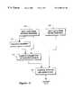
- FIG. 2is a flow diagram that illustrates the steps of a preferred method of carrying out the invention.
- FIG. 3is a drawing which depicts a specific application of the invention, namely, a helmet-mounted aircraft tracking configuration.
- FIG. 4shows the use of multiple probe sensors on a human body for sport medicine and motion capture/animation applications
- FIG. 5shows a probe sensor embedded into a stylus for medical/graphics applications
- FIG. 6shows an implementation according to the invention using multiple witness sensors on a rigid structure.
- FIG. 1illustrates, generally at 100, apparatus associated with a preferred embodiment of the invention.
- An object 102is to be tracked within a volume of interest 104 , wherein electromagnetic distortion may be present.
- One or more probe sensors 106are supported on the object to measure magnetic induction-vector components of an AC electromagnetic field 111 generated by a real, physical source 110 .
- a stationary “witness” sensor 112(or a set of sensors) having a known position and orientation is disposed at a known distance R 0 (or distances) from the source 110 .
- the witness and probe sensors 112 and 106are interconnected through paths 114 and 116 to a processor unit 120 , which outputs the position and orientation of the object 102 within the volume 106 .
- a processor unit 120which outputs the position and orientation of the object 102 within the volume 106 .
- the inventionpreferably uses multi-axis sensors measuring three components of the induction vector. Magnetic field data from each witness sensor are used by the processor unit 120 to calculate the position, strength and orientation of an “effective” source (or sources) 122 located at a distance R eff from witness sensor.
- the effective source 122is not a real source but a model source which would produce the electromagnetic field, in the vicinity of the witness sensor equivalent to the superposition of the fields from the actual source and from the electromagnetic distortion due to the eddy currents which may be present.
- the first oneis to consider a single effective source that will create the same field as the actual source plus distortion field; the second option is to consider single or multiple effective sources in addition to the actual source, thus considering the field as a superposition of the real source and the effective source(s) modeling distortion.
- the second optionis more accurate but requires more intensive real-time computations.
- the resultis used to determine the position and orientation of each probe sensor 106 and, hence, the object 102 , as measured in the non-distorted field 123 produced by the effective source 122 (or superposition of the field of the real source 110 and effective source(s) 122 ). The distortion is therefore automatically taken into account.
- Probe sensorsmay be used to determine the motion of body parts (FIG. 4) or used on surgical or digitizing instruments (FIG. 5 ).
- the inventive systemdoes not require mapping and, in fact, the witness sensor data are self-calibrating.
- the volume depicted in FIG. 1is a cube, the system works with any geometry.
- mapping approachesbenefit from the use of regular geometric volumes, since this invention does riot require a priori mapping, arbitrary volumes shapes are readily accommodated.
- the witness sensor(s)need not be placed within the volume.
- FIG. 6One of the options is illustrated in FIG. 6 . where the volume of interest is above a fixture incorporating multiple witness sensors. The only assumption underlying optimum results is that the witness sensor(s) and probe sensor(s) are close enough to one another.
- B(R 0 )be the magnetic induction vector measured by a witness sensor located at the point R 0 and a real source of the electromagnetic radiation located at the origin.
- Gis the Green's function and is the density function.
- the first term of the above equationdescribes the field created by the source at the point R 0 .
- the second termdescribes the field of the spatially distributed distortion in the sub-volumes V dist .
- any suitable alternative locationmay be used through appropriate coordinate transformation.
- multiple witness sensorse. g. N sensors
- we will get a set of N similar equations with corresponding substitution of R 0i instead of R 0 , i1.N.
- B ⁇ ( R 0 )⁇ - grad ⁇ ⁇ ⁇ V ⁇ G ⁇ ( r ) ⁇ ⁇ ⁇ ⁇ ( r ) ⁇ ⁇ 3 ⁇ r - ⁇ grad ⁇ ⁇ ⁇ ⁇ V ⁇ ⁇ eff ⁇ G ⁇ ( R 0 + R eff + r ) ⁇ ⁇ ⁇ ⁇ ( R 0 + R eff + r ) ⁇ ⁇ 3 ⁇ r
- the solution (vector) with respect to ri.e., the position of the probe sensor, defines the output of the system.
- the accuracy of the systemis enhanced through placement of the witness sensor(s) in close proximity to the probe sensor(s). That is, accuracy is increased when:
- a flow diagram of the methodis presented in FIG. 2 .
- input data from the witness sensor(s)are gathered.
- the parameters of the effective source(s)are computed, that are position and magnetic properties of the effective source(s) measured in the reference frame of the actual source. If the data from the witness sensor(s) have changed, this is taken into account at step 220 .
- input data from the probe sensor(s)are gathered.
- the position and orientation of the objectis computed relative to the coordinates of the volume of interest using the inputs from the witness and probe sensors, and the output is delivered at 210 .
- An advantage of the inventionis that the solution for the effective source may be computed at regular intervals or real-time, allowing for essentially continuous noise compensation, since witness and probe sensors are preferably at the same approximate location, and therefore nearly equally affected by the external noise. (e.g., RF).
- FIG. 3is a drawing of an aircraft cockpit application of the invention.
- a pilot 302moves within a volume 304 .
- a source 306radiates an AC electromagnetic field within the volume, which is received by at least one witness sensor 308 and at least one probe sensor 310 mounted on the helmet of the operator 302 .
- a processing unitreceives the inputs from the sensors, and computes the position and orientation of the object, in this case the helmet of the pilot, by applying the effective field generated by source 320 (or superposition of fields from 320 and 306 ) to the components of the field measured by the probe sensor 310 .
- FIG. 4shows the use of multiple probe sensors on a human body for sport medicine and motion capture/animation applications.
- FIG. 5shows a probe sensor embedded into a stylus for medical/graphics applications.
- FIG. 6shows an implementation according to the invention using multiple witness sensors on a rigid structure.
Landscapes
- Engineering & Computer Science (AREA)
- Health & Medical Sciences (AREA)
- Theoretical Computer Science (AREA)
- General Engineering & Computer Science (AREA)
- Surgery (AREA)
- Life Sciences & Earth Sciences (AREA)
- General Physics & Mathematics (AREA)
- Physics & Mathematics (AREA)
- Public Health (AREA)
- Heart & Thoracic Surgery (AREA)
- Animal Behavior & Ethology (AREA)
- General Health & Medical Sciences (AREA)
- Medical Informatics (AREA)
- Veterinary Medicine (AREA)
- Computer Networks & Wireless Communication (AREA)
- Molecular Biology (AREA)
- Biomedical Technology (AREA)
- Radar, Positioning & Navigation (AREA)
- Remote Sensing (AREA)
- Robotics (AREA)
- Human Computer Interaction (AREA)
- Nuclear Medicine, Radiotherapy & Molecular Imaging (AREA)
- Measurement Of Length, Angles, Or The Like Using Electric Or Magnetic Means (AREA)
- Position Fixing By Use Of Radio Waves (AREA)
Abstract
Description
This invention relates generally to position and orientation tracking and, in particular, to methods and apparatus for accurate position, orientation and motion-tracking within a bounded volume in the presence of electromagnetic distortion.
Existing electromagnetic tracking systems, as well as inertial and combined inertial/optical and optical/magnetic tracers, are sensitive to various kinds of distortion. With respect to electromagnetic trackers, such distortion may arise from eddy currents in metal objects or from ferromagnetic materials, whereas, in the case of inertial trackers, drift or vibration might be the cause.
In inertial tracking systems, for example, as described in U.S. Pat. No. 5,645,077, requires an additional sensor, or set of sensors, to compensate for drift and movement of a vehicle or aircraft reference frame. Even with these additional sensors, such systems exhibit sensitivity to vibration, temperature instability requiring additional compensation. Inertial tracking systems also experience drift over time periods on the order of minutes to hours.
Combination systems, that is, systems which combine optical and magnetic sensing, are designed to compensate for distortion by comparison of the data from two different types of sensors. One such system is described in U.S. Pat. No. 5,831,260 to Hansen. The use of combination systems with an optical tracking module (e. g., inertial/optical or magnetic/optical) is restricted to applications where interference associated with night-vision devices is significant, or when parasitic illumination or optical noise is present.
In an electromagnetic tracking environment, distortion may arise from eddy currents induced in nearby metal objects or from ferromagnetic materials. Eddy currents, in turn, generate fields that interfere with the field from the source(s) used for tracking purposes. To compensate for distortion of this kind, one solution involves the use of mapping. With mapping, the electromagnetic field in a volume of interest, as distorted by metal objects, is defined in advance and used to solve for position and orientation. Commonly assigned U.S. patent application Ser. No. 09/215,052, the entire contents of which are incorporated herein by reference, discloses, as part of a preferred embodiment, the use of Green's functions in conjunction with such field mapping.
The need remains, therefore, for a simple but effective approach to reducing the effects of distortion in an electromagnetic tracking system. Ideally, such a solution would be useful in a variety of applications, including military, motion capture and medical instrumentation.
The subject invention is directed to distortion compensation in electromagnetic position and orientation tracking configurations. Among the advantages over previous approaches, the invention eliminates the need for mapping in advance of actual measurements and, permits real-time adjustment in the event that new field distorters arise. This may be significant in such an environment as aircraft cockpit or tracing of medical/surgery instruments.
The invention is specifically applicable to position/orientation tracking systems of the type wherein the components of an AC electromagnetic field are sensed within a bounded volume. As in previous designs, one or more probe sensors are placed on an object being tracked within the volume, each measuring the magnetic induction vector components of the field generated by the source to determine the position, orientation and movement of the object within the volume. However, to compensate for electromagnetic distortion, the invention employs it least one stationary sensor, termed a witness sensor, in addition to the probe sensor(s) disposed on the object. Each witness sensor is supported at a known, fixed position and orientation relative to the reference frame of interest, at a point near or within the volume of interest, and close to the sensors on the object being tracked.
The outputs of each probe sensor, and each witness sensor, are delivered to a processing unit operative to compute the position and orientation of the object in the presence of electromagnetic field distorters. The processor uses data from each witness sensor to compute parameters, such as the position, orientation, and strength, of an effective electromagnetic source or sources. The effective source(s), which may be treated for the sake of simplicity as a point source (wherein the size of the source is negligible in the scale of measured distances) or a dipole (wherein the field is described by the dipole equation), would produce the same field as a superposition of the real source plus field of distortion in the proximity of witness sensors. Note that in the case of a non-distorted quiet environment, the single effective source will coincide with, and will be identical to, the actual real source. This allows the computed parameters of the effective source(s) to be used as inputs to the computation of position and orientation as measured by each probe sensor, as if the object is in the non-distorted electromagnetic field produced by the effective source(s).
An electromagnetic position/orientation tracking system according to the invention therefore preferably includes a real source of an AC electromagnetic field driven by the system; at least one witness sensor measuring electromagnetic induction vector components at a known spatial point with respect to the real source of an AC electromagnetic field; one or more probe sensors measuring electromagnetic induction vector components from the perspective of the object; and a control/processing unit providing the requisite computations. In addition to trackers for helmet-mounted displays in aircraft, tank, and armored-vehicle applications, the invention finds utility in any electromagnetic tracking system which might be subject to electromagnetic distortion or interference. Such application areas include electromagnetic motion capture systems, and medical systems and instruments, among others.
FIG. 1 is a drawing which illustrates a preferred embodiment of the invention;
FIG. 2 is a flow diagram that illustrates the steps of a preferred method of carrying out the invention; and
FIG. 3 is a drawing which depicts a specific application of the invention, namely, a helmet-mounted aircraft tracking configuration.
FIG. 4 shows the use of multiple probe sensors on a human body for sport medicine and motion capture/animation applications;
FIG. 5 shows a probe sensor embedded into a stylus for medical/graphics applications; and
FIG. 6 shows an implementation according to the invention using multiple witness sensors on a rigid structure.
FIG. 1 illustrates, generally at 100, apparatus associated with a preferred embodiment of the invention. Anobject 102 is to be tracked within a volume ofinterest 104, wherein electromagnetic distortion may be present. One ormore probe sensors 106 are supported on the object to measure magnetic induction-vector components of an ACelectromagnetic field 111 generated by a real,physical source 110. A stationary “witness” sensor112 (or a set of sensors) having a known position and orientation is disposed at a known distance R0(or distances) from thesource 110.
The witness andprobe sensors paths processor unit 120, which outputs the position and orientation of theobject 102 within thevolume 106. Although multiple, single-axis sensors may be used for the probe or witness sensors, the invention preferably uses multi-axis sensors measuring three components of the induction vector. Magnetic field data from each witness sensor are used by theprocessor unit 120 to calculate the position, strength and orientation of an “effective” source (or sources)122 located at a distance Refffrom witness sensor. Theeffective source 122 is not a real source but a model source which would produce the electromagnetic field, in the vicinity of the witness sensor equivalent to the superposition of the fields from the actual source and from the electromagnetic distortion due to the eddy currents which may be present. Depending on the required accuracy and processing time, there are at least two options to treat this effective source: the first one, is to consider a single effective source that will create the same field as the actual source plus distortion field; the second option is to consider single or multiple effective sources in addition to the actual source, thus considering the field as a superposition of the real source and the effective source(s) modeling distortion. The second option is more accurate but requires more intensive real-time computations. The result is used to determine the position and orientation of eachprobe sensor 106 and, hence, theobject 102, as measured in the non-distortedfield 123 produced by the effective source122 (or superposition of the field of thereal source 110 and effective source(s)122 ). The distortion is therefore automatically taken into account. Probe sensors may be used to determine the motion of body parts (FIG. 4) or used on surgical or digitizing instruments (FIG.5).
The inventive system does not require mapping and, in fact, the witness sensor data are self-calibrating. Although the volume depicted in FIG. 1 is a cube, the system works with any geometry. Although mapping approaches benefit from the use of regular geometric volumes, since this invention does riot require a priori mapping, arbitrary volumes shapes are readily accommodated. The witness sensor(s) need not be placed within the volume. One of the options is illustrated in FIG.6. where the volume of interest is above a fixture incorporating multiple witness sensors. The only assumption underlying optimum results is that the witness sensor(s) and probe sensor(s) are close enough to one another.
Mathematically, the arrangement may be described as follows:
Let B(R0) be the magnetic induction vector measured by a witness sensor located at the point R0and a real source of the electromagnetic radiation located at the origin. This magnetic field may be described exactly by the equation:

where G is the Green's function and is the density function.
The first term of the above equation describes the field created by the source at the point R0. The second term describes the field of the spatially distributed distortion in the sub-volumes Vdist. Note that although the actual source is placed at (0,0,0) in this case, any suitable alternative location may be used through appropriate coordinate transformation. In the case of multiple witness sensors (e. g. N sensors) we will get a set of N similar equations with corresponding substitution of R0iinstead of R0, i=1.N.
The same field B(R0) may be described approximately as the field of some effective source (the first option, as described above) located around some point Reff, as follows:


The solution of these equations with respect to Reffand □ may be found, for example, by the best-fit method or by the quasi-Newton method. It should be noted that the above equations employ the superposition principle (see references above). However, the integral over Veff may be split into few integrals over few effective volumes, e. g. Veff=Veff1+Veff2+ . . . ,in this case the solution of the above equations may be represented as a sum of few effective sources located at Reff1, Reff2, . . . , that means that superposition of the field from the actual source and distortion field will be represented by the superposition of few effective sources. The choice of the representation depends on practically required accuracy.
The solution to the above vector equation is the input to the next equation, which describes the electromagnetic field at the location of the probe sensor:

The solution (vector) with respect to r, i.e., the position of the probe sensor, defines the output of the system.
The accuracy of the system is enhanced through placement of the witness sensor(s) in close proximity to the probe sensor(s). That is, accuracy is increased when:
Multiple witness sensors increase the accuracy of the solution with respect to Reffand, in turn, r In addition, the volume wherein sufficient accuracy is achievable increases.
A flow diagram of the method is presented in FIG.2. Atstep 202, input data from the witness sensor(s) are gathered. Atblock 204 the parameters of the effective source(s) are computed, that are position and magnetic properties of the effective source(s) measured in the reference frame of the actual source. If the data from the witness sensor(s) have changed, this is taken into account atstep 220. Atstep 206, input data from the probe sensor(s) are gathered. Atstep 208, the position and orientation of the object is computed relative to the coordinates of the volume of interest using the inputs from the witness and probe sensors, and the output is delivered at210. An advantage of the invention is that the solution for the effective source may be computed at regular intervals or real-time, allowing for essentially continuous noise compensation, since witness and probe sensors are preferably at the same approximate location, and therefore nearly equally affected by the external noise. (e.g., RF).
FIG. 3 is a drawing of an aircraft cockpit application of the invention. In this case apilot 302 moves within avolume 304. Asource 306 radiates an AC electromagnetic field within the volume, which is received by at least onewitness sensor 308 and at least oneprobe sensor 310 mounted on the helmet of theoperator 302. A processing unit (not shown) receives the inputs from the sensors, and computes the position and orientation of the object, in this case the helmet of the pilot, by applying the effective field generated by source320 (or superposition of fields from320 and306) to the components of the field measured by theprobe sensor 310.
In addition to trackers for helmet-mounted displays in aircraft, tank, and armored-vehicle applications, tracing of medical/surgery instruments the invention finds utility in any electromagnetic tracking system which might be subject to electromagnetic distortion or interference. As disclosed in co-pending U.S. patent application Ser. No. 09/215,052, such application areas include electromagnetic motion capture systems, and medical systems and instruments, among others. FIG. 4 shows the use of multiple probe sensors on a human body for sport medicine and motion capture/animation applications. FIG. 5 shows a probe sensor embedded into a stylus for medical/graphics applications. FIG. 6 shows an implementation according to the invention using multiple witness sensors on a rigid structure.
Claims (28)
1. Apparatus for determining the position and orientation of an object within a bounded volume of interest in the presence of electromagnetic distortion, the apparatus comprising:
a real source of an electromagnetic field having measurable magnetic induction-vector components;
one or more stationary witness sensors supported near or within the volume of interest, each witness sensor being operative to measure the induction-vector components using a fixed known position and orientation;
one or more probe sensors supported on the object for measuring the induction-vector components; and
a processor in communication with each witness sensor and each probe sensor, the processor being operative to perform the following functions:
a) compute the characteristics of at least one effective electromagnetic source, the effective source being defined as a model source which would produce the field in the vicinity of each witness sensor similar, or identical, to the field generated by the real source, along with electromagnetic distortion present in the volume,
b) receive the induction-vector components measured by each probe sensor, and
c) compute the position and orientation of the object by applying the spatial and electromagnetic magnetic characteristics of the effective source to the induction-vector components measured by each probe sensor.
2. The apparatus ofclaim 1 , wherein:
the object moves within the volume; and
at least functions b) and c) performed by the processor are repeated at regular intervals to track the motion of the object.
3. The apparatus ofclaim 1 , wherein the computed characteristics of the effective source include the strength, position and orientation of the effective source.
4. The apparatus ofclaim 1 , wherein the bounded volume includes at least a portion of a vehicle interior, and wherein each probe sensor is supported relative to an operator of the vehicle.
5. The apparatus ofclaim 4 , wherein vehicle interior forms part of an aircraft cockpit, and wherein each probe sensor is mounted on a helmet worn by the operator.
6. The apparatus ofclaim 1 , wherein at least one probe sensor is positioned on a medical instrument.
7. The apparatus ofclaim 1 , wherein at least one probe sensor is positioned on a person's body.
8. The apparatus ofclaim 1 , including a plurality of witness sensors, and wherein the characteristics of the effective source are determined by the best-fit approximation.
9. The apparatus ofclaim 1 , including a plurality of witness sensors, and wherein the characteristics of the effective source are determined by an error minimization or optimization procedure.
10. The apparatus ofclaim 1 , wherein the effective source is treated as a point source.
11. The apparatus ofclaim 1 , wherein the effective source is treated as a dipole source.
12. The apparatus ofclaim 1 , wherein each witness sensor and each probe sensor measures orthogonal components of the magnetic induction vector given a known reference frame of witness sensor(s).
13. A method of determining the position and orientation of an object within a bounded volume in the presence of electromagnetic distortion, comprising the steps of:
a) generating an electromagnetic field having magnetic induction-vector components from a stationary source;
b) measuring the components of the electromagnetic field at one or more stationary points near or within the volume;
c) measuring the components of the electromagnetic field at one or more points relative to the object;
d) computing the characteristics of an effective electromagnetic field, which would be produced by the stationary source in the vicinity of a given witness sensor along with electromagnetic distortion present in the bounded volume;
e) receiving the induction-vector components measured relative to the object; and
f) computing the position and orientation of the object by applying the characteristics of the effective field to the induction-vector components.
14. The method ofclaim 13 , wherein:
the object moves within the volume; and
at least steps e) and f) are repeated at regular intervals to track the motion of the object.
15. The method ofclaim 13 , wherein the step of computing the characteristics of the effective electromagnetic field include computing the strength, position and orientation of the effective field.
16. The method ofclaim 13 , wherein the object is positioned within a vehicle interior.
17. The method ofclaim 13 , wherein the object is supported on the body of an individual.
18. The method ofclaim 13 , wherein the step of computing the characteristics of the effective electromagnetic field includes the step of performing a best-fit approximation.
19. The method ofclaim 13 , wherein the step of computing the characteristics of the effective electromagnetic field includes the step of performing an error minimization or optimization procedure.
20. The method ofclaim 13 , further including the step of treating the effective source as a point source.
21. The method ofclaim 13 , further including the step of treating the effective source as a dipole source.
22. The method ofclaim 13 , wherein components of the induction vector are measured at each stationary point.
23. The method ofclaim 13 , wherein components of the induction vector are measured at each point relative to the object.
24. In a position/orientation tracking system of the type wherein AC electromagnetic radiation is received by a probe sensor disposed on an object being tracked in the presence of electromagnetic distortion, the improvement comprising:
at least one witness sensor having a known fixed position and orientation within the field relative to the source of the electromagnetic distortion; and
processor means in communication with the witness sensor for:
a) computing a non-distorted model field proximate to the witness sensor, and
b) computing the position and orientation of the object with probe sensor attached to the object as if the object were located within the non-distorted model field.
25. The improvement ofclaim 24 , wherein the witness sensor is in close proximity to the object.
26. The improvement ofclaim 24 , further including a plurality of spaced-apart witness sensors.
27. The improvement ofclaim 24 , further including a plurality of sensors on the object being tracked.
28. The improvement ofclaim 24 , wherein the object is supported on a person's body.
Priority Applications (10)
| Application Number | Priority Date | Filing Date | Title |
|---|---|---|---|
| US09/430,978US6400139B1 (en) | 1999-11-01 | 1999-11-01 | Methods and apparatus for electromagnetic position and orientation tracking with distortion compensation |
| EP00975508AEP1228380A4 (en) | 1999-11-01 | 2000-10-31 | Method and apparatus for electromagnetic position and orientation tracking with distortion compensation |
| JP2001535065AJP2003513284A (en) | 1999-11-01 | 2000-10-31 | Electromagnetic position and orientation tracking method and apparatus with distortion compensation |
| CA002388328ACA2388328C (en) | 1999-11-01 | 2000-10-31 | Method and apparatus for electromagnetic position and orientation tracking with distortion compensation |
| AU13552/01AAU1355201A (en) | 1999-11-01 | 2000-10-31 | Method and apparatus for electromagnetic position and orientation tracking with distortion compensation |
| PCT/US2000/029962WO2001033231A2 (en) | 1999-11-01 | 2000-10-31 | Method and apparatus for electromagnetic position and orientation tracking with distortion compensation |
| US09/755,303US6369564B1 (en) | 1999-11-01 | 2001-01-03 | Electromagnetic position and orientation tracking system with distortion compensation employing wireless sensors |
| US10/164,081US6624626B2 (en) | 1999-11-01 | 2002-06-04 | Method and apparatus for electromagnetic position and orientation tracking with distortion compensation employing modulated signal |
| US10/428,540US20030201767A1 (en) | 1999-11-01 | 2003-05-02 | Method and apparatus for electromagnetic position and orientation tracking with distortion compensation employing a modulated signal |
| US10/699,949US6762600B2 (en) | 1999-11-01 | 2003-11-03 | Method and apparatus for electromagnetic position and orientation tracking with distortion compensation employing a modulated signal |
Applications Claiming Priority (1)
| Application Number | Priority Date | Filing Date | Title |
|---|---|---|---|
| US09/430,978US6400139B1 (en) | 1999-11-01 | 1999-11-01 | Methods and apparatus for electromagnetic position and orientation tracking with distortion compensation |
Related Child Applications (3)
| Application Number | Title | Priority Date | Filing Date |
|---|---|---|---|
| US09/755,303Continuation-In-PartUS6369564B1 (en) | 1999-11-01 | 2001-01-03 | Electromagnetic position and orientation tracking system with distortion compensation employing wireless sensors |
| US10/164,081Continuation-In-PartUS6624626B2 (en) | 1999-11-01 | 2002-06-04 | Method and apparatus for electromagnetic position and orientation tracking with distortion compensation employing modulated signal |
| US10/428,540Continuation-In-PartUS20030201767A1 (en) | 1999-11-01 | 2003-05-02 | Method and apparatus for electromagnetic position and orientation tracking with distortion compensation employing a modulated signal |
Publications (1)
| Publication Number | Publication Date |
|---|---|
| US6400139B1true US6400139B1 (en) | 2002-06-04 |
Family
ID=23709914
Family Applications (1)
| Application Number | Title | Priority Date | Filing Date |
|---|---|---|---|
| US09/430,978Expired - LifetimeUS6400139B1 (en) | 1999-11-01 | 1999-11-01 | Methods and apparatus for electromagnetic position and orientation tracking with distortion compensation |
Country Status (6)
| Country | Link |
|---|---|
| US (1) | US6400139B1 (en) |
| EP (1) | EP1228380A4 (en) |
| JP (1) | JP2003513284A (en) |
| AU (1) | AU1355201A (en) |
| CA (1) | CA2388328C (en) |
| WO (1) | WO2001033231A2 (en) |
Cited By (60)
| Publication number | Priority date | Publication date | Assignee | Title |
|---|---|---|---|---|
| US20030016006A1 (en)* | 1999-11-01 | 2003-01-23 | Igor Khalfin | Method and apparatus for electromagnetic position and orientation tracking with distortion compensation employing modulated signal |
| US20040102696A1 (en)* | 2002-11-22 | 2004-05-27 | Assaf Govari | Dynamic metal immunity |
| US20040178955A1 (en)* | 2003-03-11 | 2004-09-16 | Alberto Menache | Radio Frequency Motion Tracking System and Mehod. |
| US20040227699A1 (en)* | 2003-05-15 | 2004-11-18 | Mitchell Brian T. | Foveated display eye-tracking system and method |
| US20040239314A1 (en)* | 2003-05-29 | 2004-12-02 | Assaf Govari | Hysteresis assessment for metal immunity |
| US6831603B2 (en) | 2002-03-12 | 2004-12-14 | Menache, Llc | Motion tracking system and method |
| US20050024043A1 (en)* | 2003-07-31 | 2005-02-03 | Assaf Govari | Detection of metal disturbance in a magnetic tracking system |
| WO2004099796A3 (en)* | 2003-05-06 | 2005-03-10 | Leonard Reiffel | Stabalize position by electromagnetic field sensing |
| US20050104577A1 (en)* | 1997-02-26 | 2005-05-19 | Eusebiu Matei | System for determining relative distance(s) and/or angle(s) between at least two points |
| US20050116110A1 (en)* | 2003-08-05 | 2005-06-02 | Israel Aircraft Industries Ltd. | System and method for launching a missile from a flying aircraft |
| US20050223841A1 (en)* | 2004-04-09 | 2005-10-13 | Lee Joong K | Inductive sensor for vehicle electronic throttle control |
| US20050225320A1 (en)* | 2004-04-09 | 2005-10-13 | Lee Joong K | Inductive position sensor |
| US20060012571A1 (en)* | 2004-07-14 | 2006-01-19 | Rodgers Allan G | Head-mounted pointing and control device |
| US20060038555A1 (en)* | 2004-08-20 | 2006-02-23 | Higgins Robert F | Self-training AC magnetic tracking systems to cover large areas |
| US20060055712A1 (en)* | 2004-08-24 | 2006-03-16 | Anderson Peter T | Method and system for field mapping using integral methodology |
| US20060255795A1 (en)* | 2005-05-13 | 2006-11-16 | Higgins Robert F | Six-degree-of-freedom, integrated-coil AC magnetic tracker |
| US20070001666A1 (en)* | 2005-06-27 | 2007-01-04 | Lee Joong K | Linear and rotational inductive position sensor |
| US20070227267A1 (en)* | 2006-03-28 | 2007-10-04 | Alfred E. Mann Institute For Biomedical Engineering At The Univ. Of Southern California | Biomimetic Tactile Sensor |
| WO2007113719A1 (en)* | 2006-03-31 | 2007-10-11 | Koninklijke Philips Electronics, N.V. | System for local error compensation in electromagnetic tracking systems |
| US7292026B2 (en) | 2005-04-08 | 2007-11-06 | Ksr International Co. | Signal conditioning system for inductive position sensor |
| US20070270722A1 (en)* | 2005-07-12 | 2007-11-22 | Alfred E. Mann Institute for Biomedical Enginineering at the University of | Method and Apparatus for Detecting Object Orientation and Position |
| US20070299623A1 (en)* | 2004-11-21 | 2007-12-27 | Mark Gandelsman | Electromagnetic Tracker |
| EP1878384A2 (en) | 2006-07-11 | 2008-01-16 | Biosense Webster, Inc. | Probe for assessment of metal distortion |
| US20080033282A1 (en)* | 2006-08-07 | 2008-02-07 | Bar-Tal Meir | Distortion-immune position tracking using redundant measurements |
| US20080054887A1 (en)* | 2004-04-09 | 2008-03-06 | Lee Joong K | Inductive position sensor |
| US7355561B1 (en) | 2003-09-15 | 2008-04-08 | United States Of America As Represented By The Secretary Of The Army | Systems and methods for providing images |
| US7433728B2 (en) | 2003-05-29 | 2008-10-07 | Biosense, Inc. | Dynamic metal immunity by hysteresis |
| US20080309326A1 (en)* | 2005-12-15 | 2008-12-18 | Koninklijke Philips Electronics, N.V. | Electromagnetic Tracking Method and Apparatus for Compensation of Metal Artifacts Using Modular Arrays of Reference Sensors |
| US7471202B2 (en) | 2006-03-29 | 2008-12-30 | General Electric Co. | Conformal coil array for a medical tracking system |
| US7532997B2 (en) | 2006-04-17 | 2009-05-12 | General Electric Company | Electromagnetic tracking using a discretized numerical field model |
| US20090272201A1 (en)* | 2007-03-28 | 2009-11-05 | University Of Southern California | Enhancements to improve the function of a biomimetic tactile sensor |
| US20100009752A1 (en)* | 2008-07-10 | 2010-01-14 | Amir Rubin | Passive and active video game controllers with magnetic position sensing |
| US20100139418A1 (en)* | 2006-03-28 | 2010-06-10 | University Of Southern California | Measurement of sliding friction-induced vibrations for biomimetic tactile sensing |
| US7746321B2 (en) | 2004-05-28 | 2010-06-29 | Erik Jan Banning | Easily deployable interactive direct-pointing system and presentation control system and calibration method therefor |
| US7809421B1 (en) | 2000-07-20 | 2010-10-05 | Biosense, Inc. | Medical system calibration with static metal compensation |
| US20100309017A1 (en)* | 2009-03-11 | 2010-12-09 | Checkpoint Systems, Inc. | Localization Using Virtual Antenna Arrays In Modulated Backscatter RFID Systems |
| US20110093110A1 (en)* | 2009-10-19 | 2011-04-21 | Fives Cinetic Inc. | System and method for optimizing a production process using electromagnetic-based local positioning capabilities |
| US8391952B2 (en) | 2007-10-11 | 2013-03-05 | General Electric Company | Coil arrangement for an electromagnetic tracking system |
| WO2013154855A1 (en)* | 2012-04-10 | 2013-10-17 | Cardionxt, Inc. | System and method for localizing medical instruments during cardiovascular medical procedures |
| US20140016138A1 (en)* | 2012-07-13 | 2014-01-16 | Thales | Optical system for measuring orientation and position without image formation with point source and mask |
| US8683707B1 (en) | 2012-03-28 | 2014-04-01 | Mike Alexander Horton | Magnetically modulated location system |
| US9002437B2 (en) | 2012-12-27 | 2015-04-07 | General Electric Company | Method and system for position orientation correction in navigation |
| FR3012888A1 (en)* | 2013-11-06 | 2015-05-08 | Jean Louis Lescourret | INERTIAL HYBRID MAGNETIC SYSTEM FOR POSITION DETERMINATION AND ORIENTATION OF A MOBILE BODY |
| US9285897B2 (en) | 2005-07-13 | 2016-03-15 | Ultimate Pointer, L.L.C. | Easily deployable interactive direct-pointing system and calibration method therefor |
| US9459124B2 (en) | 2012-03-12 | 2016-10-04 | Sixense Entertainment, Inc. | Electromagnetic tracker (AC) with extended range and distortion compensation capabilities employing multiple transmitters |
| US9498143B2 (en) | 2013-08-22 | 2016-11-22 | Aftx, Inc. | Methods, systems, and apparatus for identification and characterization of rotors associated with atrial fibrillation |
| US9588582B2 (en) | 2013-09-17 | 2017-03-07 | Medibotics Llc | Motion recognition clothing (TM) with two different sets of tubes spanning a body joint |
| US10151606B1 (en) | 2016-02-24 | 2018-12-11 | Ommo Technologies, Inc. | Tracking position and movement using a magnetic field |
| WO2019016465A1 (en) | 2017-07-17 | 2019-01-24 | Sysnav | Method for locating an object moving in a magnetic field generated by an assembly of at least three magnetic generators |
| US10276289B1 (en) | 2018-06-01 | 2019-04-30 | Ommo Technologies, Inc. | Rotating a permanent magnet in a position detection system |
| CN110133582A (en)* | 2018-02-08 | 2019-08-16 | 阿森松技术公司 | Distortion in compensation electromagnetic tracking system |
| CN111796667A (en)* | 2019-04-02 | 2020-10-20 | 阿森松技术公司 | Distortion correction for tracking objects in a magnetic field |
| US10883812B2 (en) | 2018-01-19 | 2021-01-05 | Ascension Technology Corporation | Calibrating a magnetic transmitter |
| US10948278B2 (en) | 2018-01-19 | 2021-03-16 | Ascension Technology Corporation | Calibrating a magnetic sensor |
| WO2021138641A1 (en) | 2020-01-03 | 2021-07-08 | Lensar, Inc. | Integrated systems for predetermined combination laser-phacoemulsification therapies |
| US11187823B2 (en)* | 2019-04-02 | 2021-11-30 | Ascension Technology Corporation | Correcting distortions |
| US11382582B1 (en) | 2021-08-02 | 2022-07-12 | Oxos Medical, Inc. | Imaging systems and methods |
| US11432739B2 (en)* | 2016-05-03 | 2022-09-06 | St. Jude Medical International Holding S.À R.L. | Magnetic field distortion detection and correction in a magnetic localization system |
| US11832976B2 (en) | 2022-03-22 | 2023-12-05 | Oxos Medical, Inc. | Imaging systems and methods |
| US11944388B2 (en) | 2018-09-28 | 2024-04-02 | Covidien Lp | Systems and methods for magnetic interference correction |
Families Citing this family (10)
| Publication number | Priority date | Publication date | Assignee | Title |
|---|---|---|---|---|
| CA2441226C (en) | 2000-07-26 | 2013-03-12 | Northern Digital, Inc. | Method for determining the position of a sensor element |
| US20050107687A1 (en)* | 2003-11-14 | 2005-05-19 | Anderson Peter T. | System and method for distortion reduction in an electromagnetic tracker |
| JP4639199B2 (en)* | 2004-02-18 | 2011-02-23 | コーニンクレッカ フィリップス エレクトロニクス エヌ ヴィ | Measured value correction of magnetic positioning device |
| EP1998702A2 (en) | 2006-03-29 | 2008-12-10 | Stryker Corporation | Shielded surgical navigation system that determines the position and orientation of the tracked object with real and virtual dipoles |
| DE102007012361B4 (en)* | 2007-03-14 | 2016-09-22 | Siemens Healthcare Gmbh | Method for determining the position of a medical instrument and position-determining device |
| CN102307535B (en)* | 2009-01-05 | 2014-09-24 | 皇家飞利浦电子股份有限公司 | System and method for dynamic metal distortion compensation for electromagnetic tracking systems |
| US8812079B2 (en)* | 2010-12-22 | 2014-08-19 | Biosense Webster (Israel), Ltd. | Compensation for magnetic disturbance due to fluoroscope |
| US20150305823A1 (en)* | 2014-04-25 | 2015-10-29 | General Electric Company | System and method for processing navigational sensor data |
| US10285760B2 (en) | 2015-02-04 | 2019-05-14 | Queen's University At Kingston | Methods and apparatus for improved electromagnetic tracking and localization |
| IL273287B (en) | 2020-03-12 | 2022-08-01 | Elbit Systems Ltd | A system and method for calculating the configuration of the measured space |
Citations (9)
| Publication number | Priority date | Publication date | Assignee | Title |
|---|---|---|---|---|
| US4287809A (en) | 1979-08-20 | 1981-09-08 | Honeywell Inc. | Helmet-mounted sighting system |
| US4314251A (en) | 1979-07-30 | 1982-02-02 | The Austin Company | Remote object position and orientation locater |
| US4394931A (en) | 1980-04-25 | 1983-07-26 | Shell Internationale Research Maatschappij B. V. | Heat-insulated container provided with a locating and/or supporting device |
| US4737794A (en) | 1985-12-09 | 1988-04-12 | Mcdonnell Douglas Corporation | Method and apparatus for determining remote object orientation and position |
| US5453686A (en) | 1993-04-08 | 1995-09-26 | Polhemus Incorporated | Pulsed-DC position and orientation measurement system |
| EP0747662A1 (en) | 1995-06-05 | 1996-12-11 | Polhemus Incorporated | Position and orientation measuring system having anti-distortion source configuration |
| US5645077A (en) | 1994-06-16 | 1997-07-08 | Massachusetts Institute Of Technology | Inertial orientation tracker apparatus having automatic drift compensation for tracking human head and other similarly sized body |
| US5752513A (en) | 1995-06-07 | 1998-05-19 | Biosense, Inc. | Method and apparatus for determining position of object |
| US5831260A (en) | 1996-09-10 | 1998-11-03 | Ascension Technology Corporation | Hybrid motion tracker |
Family Cites Families (3)
| Publication number | Priority date | Publication date | Assignee | Title |
|---|---|---|---|---|
| DE69531994T2 (en)* | 1994-09-15 | 2004-07-22 | OEC Medical Systems, Inc., Boston | SYSTEM FOR POSITION DETECTION BY MEANS OF A REFERENCE UNIT ATTACHED TO A PATIENT'S HEAD FOR USE IN THE MEDICAL AREA |
| US5767669A (en)* | 1996-06-14 | 1998-06-16 | Ascension Technology Corporation | Magnetic field position and orientation measurement system with dynamic eddy current rejection |
| US6377041B1 (en)* | 1998-12-17 | 2002-04-23 | Polhemus Inc. | Method and apparatus for determining electromagnetic field characteristics within a volume |
- 1999
- 1999-11-01USUS09/430,978patent/US6400139B1/ennot_activeExpired - Lifetime
- 2000
- 2000-10-31EPEP00975508Apatent/EP1228380A4/ennot_activeWithdrawn
- 2000-10-31AUAU13552/01Apatent/AU1355201A/ennot_activeAbandoned
- 2000-10-31JPJP2001535065Apatent/JP2003513284A/ennot_activeCeased
- 2000-10-31WOPCT/US2000/029962patent/WO2001033231A2/ennot_activeApplication Discontinuation
- 2000-10-31CACA002388328Apatent/CA2388328C/ennot_activeExpired - Lifetime
Patent Citations (9)
| Publication number | Priority date | Publication date | Assignee | Title |
|---|---|---|---|---|
| US4314251A (en) | 1979-07-30 | 1982-02-02 | The Austin Company | Remote object position and orientation locater |
| US4287809A (en) | 1979-08-20 | 1981-09-08 | Honeywell Inc. | Helmet-mounted sighting system |
| US4394931A (en) | 1980-04-25 | 1983-07-26 | Shell Internationale Research Maatschappij B. V. | Heat-insulated container provided with a locating and/or supporting device |
| US4737794A (en) | 1985-12-09 | 1988-04-12 | Mcdonnell Douglas Corporation | Method and apparatus for determining remote object orientation and position |
| US5453686A (en) | 1993-04-08 | 1995-09-26 | Polhemus Incorporated | Pulsed-DC position and orientation measurement system |
| US5645077A (en) | 1994-06-16 | 1997-07-08 | Massachusetts Institute Of Technology | Inertial orientation tracker apparatus having automatic drift compensation for tracking human head and other similarly sized body |
| EP0747662A1 (en) | 1995-06-05 | 1996-12-11 | Polhemus Incorporated | Position and orientation measuring system having anti-distortion source configuration |
| US5752513A (en) | 1995-06-07 | 1998-05-19 | Biosense, Inc. | Method and apparatus for determining position of object |
| US5831260A (en) | 1996-09-10 | 1998-11-03 | Ascension Technology Corporation | Hybrid motion tracker |
Cited By (134)
| Publication number | Priority date | Publication date | Assignee | Title |
|---|---|---|---|---|
| US20050104577A1 (en)* | 1997-02-26 | 2005-05-19 | Eusebiu Matei | System for determining relative distance(s) and/or angle(s) between at least two points |
| US8684009B2 (en) | 1997-02-26 | 2014-04-01 | Alfred E. Mann Foundation For Scientific Research | System for determining relative distance(s) and/or angle(s) between at least two points |
| US6624626B2 (en)* | 1999-11-01 | 2003-09-23 | Polhemus Inc. | Method and apparatus for electromagnetic position and orientation tracking with distortion compensation employing modulated signal |
| US20030201767A1 (en)* | 1999-11-01 | 2003-10-30 | Igor Khalfin | Method and apparatus for electromagnetic position and orientation tracking with distortion compensation employing a modulated signal |
| US20040090226A1 (en)* | 1999-11-01 | 2004-05-13 | Igor Khalfin | Method and apparatus for electromagnetic position and orientation tracking with distortion compensation employing a modulated signal |
| US6762600B2 (en)* | 1999-11-01 | 2004-07-13 | Polhemus, Inc. | Method and apparatus for electromagnetic position and orientation tracking with distortion compensation employing a modulated signal |
| US20030016006A1 (en)* | 1999-11-01 | 2003-01-23 | Igor Khalfin | Method and apparatus for electromagnetic position and orientation tracking with distortion compensation employing modulated signal |
| US7809421B1 (en) | 2000-07-20 | 2010-10-05 | Biosense, Inc. | Medical system calibration with static metal compensation |
| US6831603B2 (en) | 2002-03-12 | 2004-12-14 | Menache, Llc | Motion tracking system and method |
| WO2003102497A1 (en)* | 2002-06-04 | 2003-12-11 | Alken Inc. Dba Polhemus | Method and apparatus for electromagnetic position and orientation tracking with distortion compensation employing modulated signal |
| US20040102696A1 (en)* | 2002-11-22 | 2004-05-27 | Assaf Govari | Dynamic metal immunity |
| US7945309B2 (en)* | 2002-11-22 | 2011-05-17 | Biosense, Inc. | Dynamic metal immunity |
| US20060125691A1 (en)* | 2003-03-11 | 2006-06-15 | Alberto Menache | Radio frequency tags for use in a motion tracking system |
| US7432810B2 (en) | 2003-03-11 | 2008-10-07 | Menache Llc | Radio frequency tags for use in a motion tracking system |
| US20040178955A1 (en)* | 2003-03-11 | 2004-09-16 | Alberto Menache | Radio Frequency Motion Tracking System and Mehod. |
| US7009561B2 (en) | 2003-03-11 | 2006-03-07 | Menache, Llp | Radio frequency motion tracking system and method |
| WO2004099796A3 (en)* | 2003-05-06 | 2005-03-10 | Leonard Reiffel | Stabalize position by electromagnetic field sensing |
| US20070001665A1 (en)* | 2003-05-06 | 2007-01-04 | Leonard Reiffel | Stabalize position by electromagnetic field sensing |
| US7872635B2 (en) | 2003-05-15 | 2011-01-18 | Optimetrics, Inc. | Foveated display eye-tracking system and method |
| US20040227699A1 (en)* | 2003-05-15 | 2004-11-18 | Mitchell Brian T. | Foveated display eye-tracking system and method |
| US20040239314A1 (en)* | 2003-05-29 | 2004-12-02 | Assaf Govari | Hysteresis assessment for metal immunity |
| US7974680B2 (en)* | 2003-05-29 | 2011-07-05 | Biosense, Inc. | Hysteresis assessment for metal immunity |
| US7433728B2 (en) | 2003-05-29 | 2008-10-07 | Biosense, Inc. | Dynamic metal immunity by hysteresis |
| US20050024043A1 (en)* | 2003-07-31 | 2005-02-03 | Assaf Govari | Detection of metal disturbance in a magnetic tracking system |
| US7321228B2 (en) | 2003-07-31 | 2008-01-22 | Biosense Webster, Inc. | Detection of metal disturbance in a magnetic tracking system |
| US20050116110A1 (en)* | 2003-08-05 | 2005-06-02 | Israel Aircraft Industries Ltd. | System and method for launching a missile from a flying aircraft |
| US7252270B2 (en) | 2003-08-05 | 2007-08-07 | Israel Aircraft Industries, Ltd. | System and method for launching a missile from a flying aircraft |
| US7355561B1 (en) | 2003-09-15 | 2008-04-08 | United States Of America As Represented By The Secretary Of The Army | Systems and methods for providing images |
| US7191759B2 (en) | 2004-04-09 | 2007-03-20 | Ksr Industrial Corporation | Inductive sensor for vehicle electronic throttle control |
| US7538544B2 (en) | 2004-04-09 | 2009-05-26 | Ksr Technologies Co. | Inductive position sensor |
| US20050223841A1 (en)* | 2004-04-09 | 2005-10-13 | Lee Joong K | Inductive sensor for vehicle electronic throttle control |
| US20050225320A1 (en)* | 2004-04-09 | 2005-10-13 | Lee Joong K | Inductive position sensor |
| US20080054887A1 (en)* | 2004-04-09 | 2008-03-06 | Lee Joong K | Inductive position sensor |
| US7276897B2 (en) | 2004-04-09 | 2007-10-02 | Ksr International Co. | Inductive position sensor |
| US9411437B2 (en) | 2004-05-28 | 2016-08-09 | UltimatePointer, L.L.C. | Easily deployable interactive direct-pointing system and presentation control system and calibration method therefor |
| US9063586B2 (en) | 2004-05-28 | 2015-06-23 | Ultimatepointer, Llc | Easily deployable interactive direct-pointing system and presentation control system and calibration method therefor |
| US11409376B2 (en) | 2004-05-28 | 2022-08-09 | UltimatePointer, L.L.C. | Multi-sensor device with an accelerometer for enabling user interaction through sound or image |
| US7746321B2 (en) | 2004-05-28 | 2010-06-29 | Erik Jan Banning | Easily deployable interactive direct-pointing system and presentation control system and calibration method therefor |
| US11416084B2 (en) | 2004-05-28 | 2022-08-16 | UltimatePointer, L.L.C. | Multi-sensor device with an accelerometer for enabling user interaction through sound or image |
| US11755127B2 (en) | 2004-05-28 | 2023-09-12 | UltimatePointer, L.L.C. | Multi-sensor device with an accelerometer for enabling user interaction through sound or image |
| US8866742B2 (en) | 2004-05-28 | 2014-10-21 | Ultimatepointer, Llc | Easily deployable interactive direct-pointing system and presentation control system and calibration method therefor |
| US11073919B2 (en) | 2004-05-28 | 2021-07-27 | UltimatePointer, L.L.C. | Multi-sensor device with an accelerometer for enabling user interaction through sound or image |
| US20100283732A1 (en)* | 2004-05-28 | 2010-11-11 | Erik Jan Banning | Easily deployable interactive direct-pointing system and presentation control system and calibration method therefor |
| US8049729B2 (en) | 2004-05-28 | 2011-11-01 | Erik Jan Banning | Easily deployable interactive direct-pointing system and presentation control system and calibration method therefor |
| US11402927B2 (en) | 2004-05-28 | 2022-08-02 | UltimatePointer, L.L.C. | Pointing device |
| US9785255B2 (en) | 2004-05-28 | 2017-10-10 | UltimatePointer, L.L.C. | Apparatus for controlling contents of a computer-generated image using three dimensional measurements |
| US20060012571A1 (en)* | 2004-07-14 | 2006-01-19 | Rodgers Allan G | Head-mounted pointing and control device |
| US7710395B2 (en) | 2004-07-14 | 2010-05-04 | Alken, Inc. | Head-mounted pointing and control device |
| US20060038555A1 (en)* | 2004-08-20 | 2006-02-23 | Higgins Robert F | Self-training AC magnetic tracking systems to cover large areas |
| US8131342B2 (en)* | 2004-08-24 | 2012-03-06 | General Electric Company | Method and system for field mapping using integral methodology |
| US20060055712A1 (en)* | 2004-08-24 | 2006-03-16 | Anderson Peter T | Method and system for field mapping using integral methodology |
| US20070299623A1 (en)* | 2004-11-21 | 2007-12-27 | Mark Gandelsman | Electromagnetic Tracker |
| US7542869B2 (en)* | 2004-11-21 | 2009-06-02 | Elbit Systems Ltd. | Electromagnetic tracker |
| US7292026B2 (en) | 2005-04-08 | 2007-11-06 | Ksr International Co. | Signal conditioning system for inductive position sensor |
| US20060255795A1 (en)* | 2005-05-13 | 2006-11-16 | Higgins Robert F | Six-degree-of-freedom, integrated-coil AC magnetic tracker |
| US20070001666A1 (en)* | 2005-06-27 | 2007-01-04 | Lee Joong K | Linear and rotational inductive position sensor |
| US20100141245A1 (en)* | 2005-06-27 | 2010-06-10 | Lee Joong K | Linear and rotational inductive position sensor |
| US7821256B2 (en) | 2005-06-27 | 2010-10-26 | Ksr Technologies Co. | Linear and rotational inductive position sensor |
| US7449878B2 (en) | 2005-06-27 | 2008-11-11 | Ksr Technologies Co. | Linear and rotational inductive position sensor |
| US8350561B2 (en) | 2005-06-27 | 2013-01-08 | Ksr Technologies Co. | Linear and rotational inductive position sensor |
| US7970477B2 (en) | 2005-07-12 | 2011-06-28 | Mann Medical Research Organization | Method and apparatus for detecting object orientation and position |
| US20070270722A1 (en)* | 2005-07-12 | 2007-11-22 | Alfred E. Mann Institute for Biomedical Enginineering at the University of | Method and Apparatus for Detecting Object Orientation and Position |
| US9285897B2 (en) | 2005-07-13 | 2016-03-15 | Ultimate Pointer, L.L.C. | Easily deployable interactive direct-pointing system and calibration method therefor |
| US11841997B2 (en) | 2005-07-13 | 2023-12-12 | UltimatePointer, L.L.C. | Apparatus for controlling contents of a computer-generated image using 3D measurements |
| US10372237B2 (en) | 2005-07-13 | 2019-08-06 | UltimatePointer, L.L.C. | Apparatus for controlling contents of a computer-generated image using 3D measurements |
| US20080309326A1 (en)* | 2005-12-15 | 2008-12-18 | Koninklijke Philips Electronics, N.V. | Electromagnetic Tracking Method and Apparatus for Compensation of Metal Artifacts Using Modular Arrays of Reference Sensors |
| US7902816B2 (en) | 2005-12-15 | 2011-03-08 | Koninklijke Philips Electronics N.V. | Electromagnetic tracking method and apparatus for compensation of metal artifacts using modular arrays of reference sensors |
| US7658119B2 (en) | 2006-03-28 | 2010-02-09 | University Of Southern California | Biomimetic tactile sensor |
| US8181540B2 (en) | 2006-03-28 | 2012-05-22 | University Of Southern California | Measurement of sliding friction-induced vibrations for biomimetic tactile sensing |
| US20100139418A1 (en)* | 2006-03-28 | 2010-06-10 | University Of Southern California | Measurement of sliding friction-induced vibrations for biomimetic tactile sensing |
| US20070227267A1 (en)* | 2006-03-28 | 2007-10-04 | Alfred E. Mann Institute For Biomedical Engineering At The Univ. Of Southern California | Biomimetic Tactile Sensor |
| US7471202B2 (en) | 2006-03-29 | 2008-12-30 | General Electric Co. | Conformal coil array for a medical tracking system |
| WO2007113719A1 (en)* | 2006-03-31 | 2007-10-11 | Koninklijke Philips Electronics, N.V. | System for local error compensation in electromagnetic tracking systems |
| JP2009531116A (en)* | 2006-03-31 | 2009-09-03 | コーニンクレッカ フィリップス エレクトロニクス エヌ ヴィ | Local error compensation system in electromagnetic tracking system |
| US20100168556A1 (en)* | 2006-03-31 | 2010-07-01 | Koninklijke Philips Electronics N.V. | System for local error compensation in electromagnetic tracking systems |
| US9733336B2 (en) | 2006-03-31 | 2017-08-15 | Koninklijke Philips N.V. | System for local error compensation in electromagnetic tracking systems |
| US7532997B2 (en) | 2006-04-17 | 2009-05-12 | General Electric Company | Electromagnetic tracking using a discretized numerical field model |
| EP1878384A3 (en)* | 2006-07-11 | 2010-07-14 | Biosense Webster, Inc. | Probe for assessment of metal distortion |
| EP1878384A2 (en) | 2006-07-11 | 2008-01-16 | Biosense Webster, Inc. | Probe for assessment of metal distortion |
| US8082020B2 (en) | 2006-08-07 | 2011-12-20 | Biosense Webster, Inc. | Distortion-immune position tracking using redundant magnetic field measurements |
| US8536859B2 (en) | 2006-08-07 | 2013-09-17 | Biosense Webster, Inc. | Distortion-immune position tracking using redundant measurements |
| US8280189B2 (en) | 2006-08-07 | 2012-10-02 | Biosense Webster, Inc. | Distortion-immune position tracking using redundant measurements |
| US20080033282A1 (en)* | 2006-08-07 | 2008-02-07 | Bar-Tal Meir | Distortion-immune position tracking using redundant measurements |
| US20090272201A1 (en)* | 2007-03-28 | 2009-11-05 | University Of Southern California | Enhancements to improve the function of a biomimetic tactile sensor |
| US8272278B2 (en) | 2007-03-28 | 2012-09-25 | University Of Southern California | Enhancements to improve the function of a biomimetic tactile sensor |
| US8391952B2 (en) | 2007-10-11 | 2013-03-05 | General Electric Company | Coil arrangement for an electromagnetic tracking system |
| US8616974B2 (en) | 2008-07-10 | 2013-12-31 | Sixense Entertainment, Inc. | Passive and active video game controllers with magnetic position sensing |
| US20100009752A1 (en)* | 2008-07-10 | 2010-01-14 | Amir Rubin | Passive and active video game controllers with magnetic position sensing |
| US20100309017A1 (en)* | 2009-03-11 | 2010-12-09 | Checkpoint Systems, Inc. | Localization Using Virtual Antenna Arrays In Modulated Backscatter RFID Systems |
| US8446253B2 (en) | 2009-03-11 | 2013-05-21 | Checkpoint Systems, Inc. | Localization using virtual antenna arrays in modulated backscatter RFID systems |
| US20110093110A1 (en)* | 2009-10-19 | 2011-04-21 | Fives Cinetic Inc. | System and method for optimizing a production process using electromagnetic-based local positioning capabilities |
| US8676368B2 (en) | 2009-10-19 | 2014-03-18 | Fives Cinetic Inc. | System and method for optimizing a production process using electromagnetic-based local positioning capabilities |
| US9459124B2 (en) | 2012-03-12 | 2016-10-04 | Sixense Entertainment, Inc. | Electromagnetic tracker (AC) with extended range and distortion compensation capabilities employing multiple transmitters |
| US8683707B1 (en) | 2012-03-28 | 2014-04-01 | Mike Alexander Horton | Magnetically modulated location system |
| WO2013154855A1 (en)* | 2012-04-10 | 2013-10-17 | Cardionxt, Inc. | System and method for localizing medical instruments during cardiovascular medical procedures |
| US9510772B2 (en) | 2012-04-10 | 2016-12-06 | Cardionxt, Inc. | System and method for localizing medical instruments during cardiovascular medical procedures |
| US10433761B2 (en) | 2012-04-10 | 2019-10-08 | Cardionxt, Inc. | Methods for localizing medical instruments during cardiovascular medical procedures |
| US20140016138A1 (en)* | 2012-07-13 | 2014-01-16 | Thales | Optical system for measuring orientation and position without image formation with point source and mask |
| US8810806B2 (en)* | 2012-07-13 | 2014-08-19 | Thales | Optical system for measuring orientation and position without image formation with point source and mask |
| US9002437B2 (en) | 2012-12-27 | 2015-04-07 | General Electric Company | Method and system for position orientation correction in navigation |
| US9498143B2 (en) | 2013-08-22 | 2016-11-22 | Aftx, Inc. | Methods, systems, and apparatus for identification and characterization of rotors associated with atrial fibrillation |
| US10588532B2 (en) | 2013-08-22 | 2020-03-17 | Aftx, Inc. | Methods, systems, and apparatus for identification and characterization of rotors associated with atrial fibrillation |
| US9955893B2 (en) | 2013-08-22 | 2018-05-01 | Aftx, Inc. | Methods, systems, and apparatus for identification and characterization of rotors associated with atrial fibrillation |
| US9588582B2 (en) | 2013-09-17 | 2017-03-07 | Medibotics Llc | Motion recognition clothing (TM) with two different sets of tubes spanning a body joint |
| FR3012888A1 (en)* | 2013-11-06 | 2015-05-08 | Jean Louis Lescourret | INERTIAL HYBRID MAGNETIC SYSTEM FOR POSITION DETERMINATION AND ORIENTATION OF A MOBILE BODY |
| WO2015067903A1 (en)* | 2013-11-06 | 2015-05-14 | Tdm | Hybrid inertial/magnetic system for determining the position and orientation of a mobile body |
| US10132636B2 (en) | 2013-11-06 | 2018-11-20 | Tdm | Hybrid inertial/magnetic system for determining the position and orientation of a mobile body |
| US10151606B1 (en) | 2016-02-24 | 2018-12-11 | Ommo Technologies, Inc. | Tracking position and movement using a magnetic field |
| US10704929B1 (en) | 2016-02-24 | 2020-07-07 | Ommo Technologies, Inc. | Tracking position and movement using a magnetic field |
| US11432739B2 (en)* | 2016-05-03 | 2022-09-06 | St. Jude Medical International Holding S.À R.L. | Magnetic field distortion detection and correction in a magnetic localization system |
| US11280928B2 (en) | 2017-07-17 | 2022-03-22 | Sysnav | Method for locating an object moving in a magnetic field generated by a set of at least three magnetic generators |
| WO2019016465A1 (en) | 2017-07-17 | 2019-01-24 | Sysnav | Method for locating an object moving in a magnetic field generated by an assembly of at least three magnetic generators |
| US11604057B2 (en) | 2018-01-19 | 2023-03-14 | Northern Digital Inc. | Calibrating a magnetic transmitter |
| US10948278B2 (en) | 2018-01-19 | 2021-03-16 | Ascension Technology Corporation | Calibrating a magnetic sensor |
| US10883812B2 (en) | 2018-01-19 | 2021-01-05 | Ascension Technology Corporation | Calibrating a magnetic transmitter |
| CN110133582A (en)* | 2018-02-08 | 2019-08-16 | 阿森松技术公司 | Distortion in compensation electromagnetic tracking system |
| CN110133582B (en)* | 2018-02-08 | 2023-09-15 | 阿森松技术公司 | Compensating for distortion in electromagnetic tracking systems |
| US10276289B1 (en) | 2018-06-01 | 2019-04-30 | Ommo Technologies, Inc. | Rotating a permanent magnet in a position detection system |
| US11944388B2 (en) | 2018-09-28 | 2024-04-02 | Covidien Lp | Systems and methods for magnetic interference correction |
| US12251174B2 (en) | 2018-09-28 | 2025-03-18 | Covidien Lp | Systems and methods for magnetic interference correction |
| US11187823B2 (en)* | 2019-04-02 | 2021-11-30 | Ascension Technology Corporation | Correcting distortions |
| CN111796667A (en)* | 2019-04-02 | 2020-10-20 | 阿森松技术公司 | Distortion correction for tracking objects in a magnetic field |
| CN111796667B (en)* | 2019-04-02 | 2024-05-31 | 北方数字化技术公司 | Distortion correction for tracking objects in magnetic fields |
| EP4218694A1 (en) | 2020-01-03 | 2023-08-02 | Lensar, Inc. | Methods and systems for combined sonic and laser applications for the eye |
| EP4218695A1 (en) | 2020-01-03 | 2023-08-02 | Lensar, Inc. | Integrated systems for predetermined combination laser-phacoemulsification therapies |
| EP4389045A2 (en) | 2020-01-03 | 2024-06-26 | Lensar, Inc. | Methods and systems for combined sonic and laser applications for the eye |
| WO2021138641A1 (en) | 2020-01-03 | 2021-07-08 | Lensar, Inc. | Integrated systems for predetermined combination laser-phacoemulsification therapies |
| US11931193B2 (en) | 2021-08-02 | 2024-03-19 | Oxos Medical, Inc. | Imaging systems and methods |
| US11864937B2 (en) | 2021-08-02 | 2024-01-09 | Oxos Medical, Inc. | Imaging systems and methods |
| US11684330B2 (en) | 2021-08-02 | 2023-06-27 | Oxos Medical, Inc. | Imaging systems and methods |
| US12115010B2 (en) | 2021-08-02 | 2024-10-15 | Oxos Medical, Inc. | Imaging systems and methods |
| US11382582B1 (en) | 2021-08-02 | 2022-07-12 | Oxos Medical, Inc. | Imaging systems and methods |
| US12295763B2 (en) | 2021-08-02 | 2025-05-13 | Oxos Medical, Inc. | Imaging systems and methods |
| US11832976B2 (en) | 2022-03-22 | 2023-12-05 | Oxos Medical, Inc. | Imaging systems and methods |
Also Published As
| Publication number | Publication date |
|---|---|
| WO2001033231A2 (en) | 2001-05-10 |
| AU1355201A (en) | 2001-05-14 |
| WO2001033231A3 (en) | 2001-12-06 |
| JP2003513284A (en) | 2003-04-08 |
| EP1228380A4 (en) | 2006-04-12 |
| CA2388328A1 (en) | 2001-05-10 |
| EP1228380A2 (en) | 2002-08-07 |
| CA2388328C (en) | 2009-12-29 |
Similar Documents
| Publication | Publication Date | Title |
|---|---|---|
| US6400139B1 (en) | Methods and apparatus for electromagnetic position and orientation tracking with distortion compensation | |
| US6369564B1 (en) | Electromagnetic position and orientation tracking system with distortion compensation employing wireless sensors | |
| US6377041B1 (en) | Method and apparatus for determining electromagnetic field characteristics within a volume | |
| Bhatnagar | Position trackers for head mounted display systems: A survey | |
| US6789043B1 (en) | Magnetic sensor system for fast-response, high resolution, high accuracy, three-dimensional position measurements | |
| Krybus et al. | Navigation support for surgery by means of optical position detection | |
| ES2272904T3 (en) | POSITIONING SYSTEM WITH DYNAMIC METAL IMMUNITY. | |
| US10095815B2 (en) | System and a method for mapping a magnetic field | |
| US6605041B2 (en) | 3-D ultrasound recording device | |
| CN102307535B (en) | System and method for dynamic metal distortion compensation for electromagnetic tracking systems | |
| US11513168B2 (en) | Magnetic field probe for determining a disposition of an implantable magnetic marker | |
| US20070299623A1 (en) | Electromagnetic Tracker | |
| EP2888997B1 (en) | Adaptive fluoroscope location for the application of field compensation | |
| US20010030754A1 (en) | Body spatial dimension mapper | |
| GB2408805A (en) | Wireless electromagnetic position tracking | |
| US20240299099A1 (en) | Intraoperative Stereotaxic Navigation Systems | |
| US6296613B1 (en) | 3D ultrasound recording device | |
| US10488471B2 (en) | System and a method for mapping a magnetic field | |
| US12144664B2 (en) | Method and positioning system for determining a region to be examined in a subject | |
| KR20040103415A (en) | Dynamic metal immunity by hysteresis | |
| JP5131851B2 (en) | Biological signal measurement system | |
| EP3129801B1 (en) | A system and a method for mapping a magnetic field | |
| WO2000017603A1 (en) | Magnetic sensor system for fast-response, high resolution, high accuracy, three-dimensional position measurements | |
| Remmel | Use of an electromagnetic eye movement monitor for easy measurement of arm movements | |
| JP2025065628A (en) | DATA PROCESSING METHOD, PROGRAM, AND DATA PROCESSING SYSTEM |
Legal Events
| Date | Code | Title | Description |
|---|---|---|---|
| AS | Assignment | Owner name:POLHEMUS INC., VERMONT Free format text:ASSIGNMENT OF ASSIGNORS INTEREST;ASSIGNORS:KHALFIN, IGOR;JONES, HERBERT R., JR.;REEL/FRAME:010373/0190 Effective date:19991021 | |
| FEPP | Fee payment procedure | Free format text:PAT HOLDER CLAIMS SMALL ENTITY STATUS, ENTITY STATUS SET TO SMALL (ORIGINAL EVENT CODE: LTOS); ENTITY STATUS OF PATENT OWNER: SMALL ENTITY | |
| STCF | Information on status: patent grant | Free format text:PATENTED CASE | |
| CC | Certificate of correction | ||
| AS | Assignment | Owner name:CHITTENDEN BANK, VERMONT Free format text:ASSIGNMENT OF ASSIGNORS INTEREST;ASSIGNOR:POLHEMUS INCORPORATED;REEL/FRAME:013964/0214 Effective date:20020927 | |
| FPAY | Fee payment | Year of fee payment:4 | |
| FPAY | Fee payment | Year of fee payment:8 | |
| FEPP | Fee payment procedure | Free format text:PAT HOLDER CLAIMS SMALL ENTITY STATUS, ENTITY STATUS SET TO SMALL (ORIGINAL EVENT CODE: LTOS); ENTITY STATUS OF PATENT OWNER: SMALL ENTITY | |
| FPAY | Fee payment | Year of fee payment:12 |