US6400043B1 - Modular uninterruptable power supply - Google Patents
Modular uninterruptable power supplyDownload PDFInfo
- Publication number
- US6400043B1 US6400043B1US09/451,386US45138699AUS6400043B1US 6400043 B1US6400043 B1US 6400043B1US 45138699 AUS45138699 AUS 45138699AUS 6400043 B1US6400043 B1US 6400043B1
- Authority
- US
- United States
- Prior art keywords
- battery
- node
- terminal
- transformer winding
- circuit
- Prior art date
- Legal status (The legal status is an assumption and is not a legal conclusion. Google has not performed a legal analysis and makes no representation as to the accuracy of the status listed.)
- Expired - Lifetime
Links
- 238000004804windingMethods0.000claimsabstractdescription85
- 230000001939inductive effectEffects0.000claimsabstractdescription4
- XUIMIQQOPSSXEZ-UHFFFAOYSA-NSiliconChemical compound[Si]XUIMIQQOPSSXEZ-UHFFFAOYSA-N0.000claimsdescription17
- 229910052710siliconInorganic materials0.000claimsdescription17
- 239000010703siliconSubstances0.000claimsdescription17
- 230000005669field effectEffects0.000claimsdescription13
- 230000008878couplingEffects0.000claimsdescription11
- 238000010168coupling processMethods0.000claimsdescription11
- 238000005859coupling reactionMethods0.000claimsdescription11
- 230000000295complement effectEffects0.000claimsdescription5
- 238000013022ventingMethods0.000claimsdescription2
- 238000010586diagramMethods0.000description2
- 230000001131transforming effectEffects0.000description2
- 230000008901benefitEffects0.000description1
- 230000008859changeEffects0.000description1
- 238000001816coolingMethods0.000description1
- 238000005516engineering processMethods0.000description1
- 238000001914filtrationMethods0.000description1
- 238000009434installationMethods0.000description1
- 238000012423maintenanceMethods0.000description1
- 238000012986modificationMethods0.000description1
- 230000004048modificationEffects0.000description1
- 230000003071parasitic effectEffects0.000description1
- 230000009467reductionEffects0.000description1
Images

Classifications
- H—ELECTRICITY
- H02—GENERATION; CONVERSION OR DISTRIBUTION OF ELECTRIC POWER
- H02J—CIRCUIT ARRANGEMENTS OR SYSTEMS FOR SUPPLYING OR DISTRIBUTING ELECTRIC POWER; SYSTEMS FOR STORING ELECTRIC ENERGY
- H02J9/00—Circuit arrangements for emergency or stand-by power supply, e.g. for emergency lighting
- H02J9/04—Circuit arrangements for emergency or stand-by power supply, e.g. for emergency lighting in which the distribution system is disconnected from the normal source and connected to a standby source
- H02J9/06—Circuit arrangements for emergency or stand-by power supply, e.g. for emergency lighting in which the distribution system is disconnected from the normal source and connected to a standby source with automatic change-over, e.g. UPS systems
- H02J9/062—Circuit arrangements for emergency or stand-by power supply, e.g. for emergency lighting in which the distribution system is disconnected from the normal source and connected to a standby source with automatic change-over, e.g. UPS systems for AC powered loads
- H—ELECTRICITY
- H02—GENERATION; CONVERSION OR DISTRIBUTION OF ELECTRIC POWER
- H02J—CIRCUIT ARRANGEMENTS OR SYSTEMS FOR SUPPLYING OR DISTRIBUTING ELECTRIC POWER; SYSTEMS FOR STORING ELECTRIC ENERGY
- H02J5/00—Circuit arrangements for transfer of electric power between AC networks and DC networks
- H—ELECTRICITY
- H02—GENERATION; CONVERSION OR DISTRIBUTION OF ELECTRIC POWER
- H02J—CIRCUIT ARRANGEMENTS OR SYSTEMS FOR SUPPLYING OR DISTRIBUTING ELECTRIC POWER; SYSTEMS FOR STORING ELECTRIC ENERGY
- H02J7/00—Circuit arrangements for charging or depolarising batteries or for supplying loads from batteries
- H02J7/02—Circuit arrangements for charging or depolarising batteries or for supplying loads from batteries for charging batteries from AC mains by converters
- H—ELECTRICITY
- H02—GENERATION; CONVERSION OR DISTRIBUTION OF ELECTRIC POWER
- H02J—CIRCUIT ARRANGEMENTS OR SYSTEMS FOR SUPPLYING OR DISTRIBUTING ELECTRIC POWER; SYSTEMS FOR STORING ELECTRIC ENERGY
- H02J9/00—Circuit arrangements for emergency or stand-by power supply, e.g. for emergency lighting
- H02J9/04—Circuit arrangements for emergency or stand-by power supply, e.g. for emergency lighting in which the distribution system is disconnected from the normal source and connected to a standby source
- H02J9/06—Circuit arrangements for emergency or stand-by power supply, e.g. for emergency lighting in which the distribution system is disconnected from the normal source and connected to a standby source with automatic change-over, e.g. UPS systems
- H02J9/067—Circuit arrangements for emergency or stand-by power supply, e.g. for emergency lighting in which the distribution system is disconnected from the normal source and connected to a standby source with automatic change-over, e.g. UPS systems using multi-primary transformers, e.g. transformer having one primary for each AC energy source and a secondary for the loads
Definitions
- the present inventionrelates to power supplies and, more specifically, to an uninterruptable power supply.
- Existing uninterruptable power suppliessupply back up alternating current to electronic components in the event of normal power interruption.
- Such power suppliestypically include a rechargeable battery, a rectifier circuit for recharging the battery and an inverter for producing alternating current from the battery. They also include a transformer that includes windings for transforming normal service power to a load, auxiliary windings for battery charging, and windings for transforming battery-supplied alternating current to a load.
- the auxiliary windingsadd cost and complexity to the power supply.
- existing power suppliesare susceptible to certain damage from battery lead reversal or short-circuit.
- Such existing power suppliesare typically sold as single units that are bulky to ship and require replacement of the entire unit if a single component fails.
- the likelihood of component failureis increased as a result of there being a common housing for both the transformer, and the associated electronics. This is because removal of heat from all of the components usually requires a fan that is subject to mechanical failure.
- a power supply produced as a single unitdoes not lend itself to upgrading of a single component. Upgrading of electronics occurs relatively frequently because advances in electronics occur relatively frequently, but upgrading of transformers does not occur as frequently because transformer technology does not change as frequently.
- the disadvantages of the prior artare overcome by the present invention which, in one aspect, is an uninterruptable power supply with an external or internal rechargeable battery having a positive terminal and a negative terminal, and a transformer.
- the transformerincludes: a battery side transformer winding having a first terminal, a second terminal and a third terminal; a load side transformer winding inductively coupled to the battery side transformer winding via a core; and a power supply side transformer winding that is inductively coupled to the battery side transformer winding via the core.
- An inverter circuitcouples the positive terminal of the battery to the first terminal of the battery side transformer winding and couples the negative terminal of the battery to the second terminal and the third terminal of the battery side transformer winding.
- the inverter circuitincludes a switching circuit that forms a bridge rectifier circuit that allows current from the battery side transformer winding to flow in only one direction into the battery when the switching circuit is in a first switching state (operating from mains) so that current from the power supply side transformer winding induces an alternating current in the battery side transformer winding that passes through the bridge circuit to generate a direct current that charges the battery when the switching circuit is in the first switching state.
- the switching circuitalso forms a push-pull inverter circuit that generates an alternating current from a direct current supplied by the battery when the switching circuit is in a second switching state (operating from batteries), thereby inducing an alternating current in the load side transformer winding.
- a control circuitdrives the switching circuit into the first switching state when at least a predetermined power level is supplied to the power side transformer winding.
- the control circuitalso drives the switching circuit into the second switching state when less than the predetermined power level is supplied to the power side transformer winding.
- the mode switching circuitprovides protection from battery lead reversal or short-circuits, such as may occur during installation or maintenance.
- the inventionis an uninterruptable power supply that includes a transformer module that is disposed in a first enclosure.
- the transformer moduleincludes a transformer that is couplable to both a charging power source and a load.
- the first enclosureincludes a first interior wall with a first electrical connector affixed thereto.
- the first electrical connectoris electrically coupled to a battery side winding of the transformer.
- the uninterruptable power supplyalso includes an electronics module disposed in a second enclosure different from the first enclosure.
- the second enclosureincludes a second interior wall that is complementary in shape to the first interior wall.
- the electronics moduleinterfaces to an internal or external rechargeable battery that is capable of supplying a direct current.
- the moduleincludes an inverter, electrically coupled to the battery, that is capable of generating an alternating current from the direct current; a recharging circuit that is capable of selectively providing direct current to the battery; and a second electrical connector, affixed to the second interior wall and complementary to the first electrical connector.
- the second electrical connectoris electrically coupled to both the inverter and the recharging circuit so that both the inverter and the recharging circuit may be electrically coupled to the battery side winding of the transformer by physically coupling the first electrical connector to the second electrical connector.
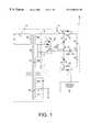
- FIG. 1is a schematic diagram of a circuit in accordance with one embodiment of the invention.
- FIG. 2is a block diagram showing one layout of the major elements of one embodiment of the invention.
- the inventionis an uninterruptable power supply 10 that includes an inverter and charging circuit 20 and a control circuit 80 as part of an electronics module and a transformer module 60 .
- the inverter and charging circuit 20connects to an internal or external rechargeable battery 40 having a positive terminal and a negative terminal.
- the transformer module 60houses a transformer that includes a battery side transformer winding 64 (shown as having a first portion 64 a and a second portion 64 b ) having a first terminal 12 , a second terminal 16 and a third terminal 14 .
- a load side transformer winding 66(shown as having a first portion 66 a and a second portion 66 b ) is inductively coupled to the battery side transformer winding 64 via a core 62 .
- the load side transformer winding 66may be electrically coupled to a load 70 .
- a power supply side tansformer winding 68capable of receiving normal service power 76 , is also inductively coupled to the battery side transformer winding 64 via the core.
- a switch 74may be supplied to isolate the power supply side transformer winding 68 from service power 76 .
- the inverter, and charging circuit 20couples the positive terminal 40 a of the battery 40 to the first terminal 12 of the battery side transformer winding 64 and couples the negative terminal of the battery 40 b to the second terminal 16 and the third terminal 14 of the battery side transformer winding 64 .
- the inverter and charging circuit 20includes a switching circuit 22 that forms a bridge circuit that allows current from the battery side transformer winding 64 to flow in only one direction into the battery 40 when the switching circuit 50 is in a first switching state.
- the first switching statemay be electrically defined as having thyristors 54 and 56 , and relay 52 de-energized and open, and relay 74 de-energized and closed.
- the switching circuit 22also forms a push-pull inverter circuit that generates an alternating current from a direct current supplied by the battery 40 when the switching circuit 22 is in a second switching state, thereby inducing an alternating current in the load side transformer winding 66 .
- the second switching statemay be defined as having thyristors 54 and 56 , and relay 52 energized and closed, and relay 74 energized and open.
- a control circuit 80drives the switching circuits 22 and 50 into the first switching state when at least a predetermined power level is supplied to the power side transformer winding 68 (i.e., when normal power is being supplied to the power side transformer winding 68 ).
- the control circuit 80drives the switching circuits 22 and 50 into the second switching state when less than the predetermined power level is supplied to the power side transformer winding 68 (i.e., when normal power to the power side transformer winding 68 is interrupted, such as due to a power outage).
- the inverter and charging circuit 20has a first node 24 electrically coupled to the positive terminal 40 a of the battery 40 , a second node 26 electrically coupled to the second terminal 16 of the battery side winding 64 , a third node 28 electrically coupled to the negative terminal 40 b of the battery 40 and a fourth node 30 electrically coupled to the third terminal 14 of the battery side winding 64 .
- the inverter and charging circuit 20includes a first transistor 36 coupling the second node 26 to the third node 28 and biased so as to be capable of conducting current in either direction between the third node 28 and the second node 26 when the first transistor 36 is in a first transistor state.
- the first transistor 36is capable of conducting current flowing only from the second node 26 to the third node 28 when the first transistor 36 is in a second transistor state (to demonstrate this relationship, FIG. I shows the first transistor 36 as a field effect transistor (FET) in parallel with a diode).
- FETfield effect transistor
- the inverter and charging circuit 20may also include current sensors 42 and 44 to sense current flow to the battery 40 .
- a second transistor 38couples the fourth node 30 to the third node 28 and is biased so as to be capable of conducting current flowing in either direction between the third node 28 and the fourth node 30 when the second transistor 38 is in a first transistor state and capable of conducting current flowing only from the fourth node 30 to the third node 28 when the second transistor 38 is in a second transistor state.
- the first transistor state and the second transistor stateis determined by a signal level supplied to the gating junction of the first transistor and the second transistor by the control circuit 80 .
- Fuses 46 and 48may also be provided for circuit protection.
- a first silicon controlled rectifier (SCR) 32electrically couples the second node 26 to the first node 24 and is biased so as to be capable of conducting current flowing only from the second node 26 to the first node 24 when the first SCR 32 is in a conductive state.
- the first SCR 32also acts as an open circuit when the first SCR 32 is in a non-conductive state.
- a second SCR 34electrically couples the fourth node 30 to the first node 24 and is biased so as to be capable of conducting current flowing only from the fourth node 30 to the first node 24 when the second SCR is in a conductive state.
- the second SCR 34also acts as an open circuit when the second SCR is in a non-conductive state. Whether the first SCR 32 and the second SCR 34 are in the conductive state depends on a signal value from the control circuit 80 applied to the control input of the SCR.
- the control circuit 80(the function of which includes that of an inverter control circuit) is electrically coupled to the gates of the first transistor 36 and to the second transistor 38 .
- the control circuit 80alternately generates a first inverter control signal value and a second inverter control signal value when the switching circuit 22 is in a second switching state.
- the first inverter control signal valuedrives the first transistor 36 into the first transistor state and the second transistor 38 into the second transistor state.
- the second inverter control signal valuedrives the first FET 36 into the second transistor state and the second FET 38 into the first transistor state.
- a power supply switch 50electrically couples the positive terminal 40 a of the battery to the first terminal 12 of the battery side transformer winding 64 when the switching circuit 22 is in the second switching state and electrically decouples the positive terminal 40 a of the battery from the first terminal 12 of the battery side transformer winding 64 when the switching circuit 22 is in the first switching state.
- the power supply switch 50includes a relay 52 that electrically couples the positive terminal 40 a of the battery 40 to the first terminal 12 of the battery side transformer winding 64 when the relay 52 is closed and that electrically decouples the positive terminal 40 a of the battery 40 from the first terminal 12 of the battery side transformer winding 64 when the relay 52 is open.
- the power supply switch 50includes a third SCR 56 that allows current to flow in a first direction and fourth SCR 54 that allows current to flow in a second direction opposite the first direction.
- the third SCR 56 and the fourth SCR 54are electrically coupled in parallel so that current may flow in either the first direction or the second direction when both the third SCR 56 and the fourth SCR 54 are in a conductive state.
- the third SCR 56 and the fourth SCR 54electrically couple the positive terminal 40 a of the battery 40 to the first terminal 12 of the battery side transformer winding 64 when they are in a transmissive state.
- the third SCR 56 and the fourth SCR 54are driven to the transmissive state and the relay 52 is closed by the control circuit 80 upon to onset of a interruption of service power 76 to the power supply side transformer winding 68 .
- An inductor 58electrically coupling charging SCRs 32 and 34 to the battery positive terminal 40 a , provides charge current ripple filtering when the circuit is in the first switching state.
- the inverter and charging circuit 20 and the switch circuit 50 of this embodiment of the inventionallows the battery side winding 64 to be used both in recharging the battery 40 when normal power is available and in supplying back up power from the battery 40 when normal power is interrupted. This is done without requiring an extra winding.
- Switch circuit 50being normally open, additionally prevents damaging currents from flowing if battery 40 is connected backwards or if the battery connecting leads are shorted during product application.
- the uninterruptable power supplyincludes a transformer module 160 , disposed in a first enclosure 162 .
- the transformer module 160includes a transformer 110 that is couplable to both a charging power source 76 and a load 70 .
- the first enclosure 162includes a first interior wall 164 and a first electrical connector 114 (which could be, e.g., either a male electrical plug or a female electrical plug) affixed thereto.
- the first electrical connector 114is electrically coupled to a battery side winding 64 (as shown in FIG. 1) of the transformer 110 .
- the transformer modulealso includes an opening for venting heat from the transformer module.
- An electronics module 120is disposed in a second enclosure 122 .
- the second enclosure 122includes a second interior wall 130 that is complementary in shape to the first interior wall 164 .
- the electronics moduleincludes continuous power supply electronics 124 , such as the control circuits, an inverter and a recharging circuit (examples of these items were discussed above with reference to the embodiment shown in FIG. 1 ).
- a second electrical connector 128(which could be, e.g., either a male electrical plug or a female electrical plug, so long as it is of opposite gender from the first electrical connector 114 ) is affixed to the second interior wall 130 and is complementary to the first electrical connector 114 .
- the second electrical connector 128is electrically coupled to both the inverter and the recharging circuit. Both the inverter and the recharging circuit may be electrically coupled to the battery side winding of the transformer 110 by physically coupling the first electrical connector 114 to the second electrical connector 128 .
- the electronics module 120may also include a heat sink 126 disposed along an exterior surface of the electronics module 120 and spaced apart from the second interior wall 130 so as to transmit from the electronics module 120 at least a portion of any heat generated within the electronics module 120 . Placing the heat sink 126 away from the transformer 110 simplifies cooling of the power supply.
- One or more voltage control jumpers 112may be disposed on the first interior wall 112 to allow for changes in voltage standard of the power source 76 , etc. By placing the jumpers 112 on the first interior wall 112 , they will be accessible when the first electrical connector 114 is not physically coupled to the second electrical connector 128 , but will be inaccessible when the first electrical connector 114 is physically coupled to the second electrical connector 128 , thereby preventing unauthorized access to the jumpers 112 .
- the modularity of this embodiment of the inventionallows the uninterruptable power supply to be shipped, sold, upgraded, or installed as separate units. Also, by separating the transformer module 160 from the electronics module 120 , heat removal becomes less costly and makes the power supply less susceptible to heat-related failure.
Landscapes
- Engineering & Computer Science (AREA)
- Power Engineering (AREA)
- Business, Economics & Management (AREA)
- Emergency Management (AREA)
- Charge And Discharge Circuits For Batteries Or The Like (AREA)
Abstract
Description
Claims (11)
Priority Applications (1)
| Application Number | Priority Date | Filing Date | Title |
|---|---|---|---|
| US09/451,386US6400043B1 (en) | 1998-11-30 | 1999-11-30 | Modular uninterruptable power supply |
Applications Claiming Priority (2)
| Application Number | Priority Date | Filing Date | Title |
|---|---|---|---|
| US11025698P | 1998-11-30 | 1998-11-30 | |
| US09/451,386US6400043B1 (en) | 1998-11-30 | 1999-11-30 | Modular uninterruptable power supply |
Publications (1)
| Publication Number | Publication Date |
|---|---|
| US6400043B1true US6400043B1 (en) | 2002-06-04 |
Family
ID=26807848
Family Applications (1)
| Application Number | Title | Priority Date | Filing Date |
|---|---|---|---|
| US09/451,386Expired - LifetimeUS6400043B1 (en) | 1998-11-30 | 1999-11-30 | Modular uninterruptable power supply |
Country Status (1)
| Country | Link |
|---|---|
| US (1) | US6400043B1 (en) |
Cited By (23)
| Publication number | Priority date | Publication date | Assignee | Title |
|---|---|---|---|---|
| US20040236933A1 (en)* | 2003-05-20 | 2004-11-25 | Dewey Thomas E. | Simplified memory detection |
| US20040233589A1 (en)* | 2003-05-20 | 2004-11-25 | Dewey Thomas E. | Package-based voltage control |
| US20050036248A1 (en)* | 2003-08-15 | 2005-02-17 | American Power Conversion Corporation | Uninterruptible power supply |
| US20050162836A1 (en)* | 2004-01-23 | 2005-07-28 | James Briggs | Modular UPS |
| US20050162129A1 (en)* | 2004-01-23 | 2005-07-28 | Srdan Mutabdzija | Method and apparatus for monitoring energy storage devices |
| US20050164563A1 (en)* | 2004-01-23 | 2005-07-28 | David Schuttler | Power terminal block |
| US20050162019A1 (en)* | 2004-01-23 | 2005-07-28 | Masciarelli Francis J. | Methods and apparatus for providing uninterruptible power |
| US20050225914A1 (en)* | 2002-07-31 | 2005-10-13 | Steve King | Power supply |
| US20060238031A1 (en)* | 2005-04-26 | 2006-10-26 | Wilfred Frey | DC and AC uninterruptible power supply |
| US20070245012A1 (en)* | 1996-07-23 | 2007-10-18 | Server Technology, Inc. | Remote power control system with tickle capability |
| US20070262650A1 (en)* | 2006-05-09 | 2007-11-15 | Delta Electronics, Inc. | Uninterruptible power supply with low power loss |
| US20070273212A1 (en)* | 2004-04-14 | 2007-11-29 | Phoenix Contact Gmbh & Co. Kg | Device for supplying uninterruptible power |
| US20090039706A1 (en)* | 2007-08-10 | 2009-02-12 | American Power Conversion Corporation | Input and output power modules configured to provide selective power to an uninterruptible power supply |
| CN100544158C (en)* | 2006-05-17 | 2009-09-23 | 台达电子工业股份有限公司 | Low-power-consumption uninterrupted power supply system |
| US20120195081A1 (en)* | 2011-01-27 | 2012-08-02 | Lineage Power Corporation | System and method for increasing dc power system efficiency without requiring a large battery reserve |
| US8552589B2 (en) | 2010-05-14 | 2013-10-08 | Schneider Electric It Corporation | Digital control method for operating the UPS systems in parallel |
| US9104393B2 (en) | 1996-07-23 | 2015-08-11 | Server Technology, Inc. | Power-manager configuration upload and download method and system for network managers |
| US20160190950A1 (en)* | 2014-02-21 | 2016-06-30 | Varentec, Inc. | Methods and systems of field upgradeable transformers |
| WO2016183076A1 (en) | 2015-05-11 | 2016-11-17 | Hindle Power, Inc. | System and method for monitoring a dc power system |
| US9952103B2 (en) | 2011-12-22 | 2018-04-24 | Schneider Electric It Corporation | Analysis of effect of transient events on temperature in a data center |
| US9985450B2 (en)* | 2016-05-12 | 2018-05-29 | Littelfuse, Inc. | Relay for use with multiple power sources |
| CN110793138A (en)* | 2019-11-26 | 2020-02-14 | 开平市高美空调设备有限公司 | Energy-saving air conditioner capable of storing electricity |
| US11076507B2 (en) | 2007-05-15 | 2021-07-27 | Schneider Electric It Corporation | Methods and systems for managing facility power and cooling |
Citations (23)
| Publication number | Priority date | Publication date | Assignee | Title |
|---|---|---|---|---|
| US4638178A (en)* | 1985-09-03 | 1987-01-20 | Wang Laboratories, Inc. | Modular power system |
| US4675538A (en)* | 1986-06-02 | 1987-06-23 | Epstein Barry M | General purpose uninterruptible power supply |
| US4745299A (en)* | 1986-04-17 | 1988-05-17 | American Telephone And Telegraph Company, At&T Bell Laboratories | Off-line switcher with battery reserve |
| US4748342A (en)* | 1985-12-18 | 1988-05-31 | U.S. Philips Corporation | Power supply circuit |
| US5182518A (en)* | 1991-04-11 | 1993-01-26 | Best Power Technology, Inc. | Inverter and battery testing for uninterruptible power systems |
| US5483463A (en)* | 1993-07-30 | 1996-01-09 | Controlled Power Company | Uninterruptible power supply (UPS) and method |
| US5563778A (en)* | 1993-12-21 | 1996-10-08 | Lg Industrial Systems Co., Ltd. | Uninterruptible power supply system |
| US5615129A (en)* | 1995-02-21 | 1997-03-25 | General Signal Power Systems, Inc. | Method and apparatus for adaptive and corrective determination of battery run-time in uninterruptible power systems |
| US5616968A (en)* | 1993-12-24 | 1997-04-01 | Omron Corporation | Expandable AC power supply device |
| US5670833A (en)* | 1994-11-23 | 1997-09-23 | General Signal Power Systems, Inc. | Power transfer method and apparatus for uninterruptible power systems |
| US5760495A (en)* | 1995-02-22 | 1998-06-02 | Alpha Technologies, Inc. | Inverter/charger circuit for uninterruptible power supplies |
| US5801513A (en)* | 1996-12-31 | 1998-09-01 | Motorola, Inc. | Apparatus for charging batteries and supplying backup power |
| US5804890A (en)* | 1995-07-07 | 1998-09-08 | Lucent Technologies Inc. | Direct current voltage power backup system |
| US5845217A (en)* | 1993-09-15 | 1998-12-01 | Ericsson Inc. | Power systems for plug-in modules |
| US5856712A (en)* | 1996-12-05 | 1999-01-05 | I-Hits Laboratory | Uninterruptible power supply method |
| US5886880A (en)* | 1997-05-28 | 1999-03-23 | Nec Corporation | Power circuit for transferring energy by alternately switching winding circuits of a transformer at high speed |
| US6115268A (en)* | 1997-08-11 | 2000-09-05 | Delta Electronics Inc. | Method and apparatus for supplying uninterrupted power |
| US6121756A (en)* | 1997-11-25 | 2000-09-19 | Powerware Corporation | Charger |
| US6121695A (en)* | 1995-10-11 | 2000-09-19 | Invetech Operations Pty. Ltd. | Modular power supply |
| US6198177B1 (en)* | 2000-01-07 | 2001-03-06 | Lucent Technologies Inc. | Power supply providing backup AC voltage and method of operation thereof |
| US6201319B1 (en)* | 1998-07-14 | 2001-03-13 | American Power Conversion | Uninterruptible power supply |
| US6218744B1 (en)* | 1999-03-22 | 2001-04-17 | Powerware Corporation | Uninterruptible power supply and ferroresonant transformer for use therewith |
| US6339314B1 (en)* | 2000-12-27 | 2002-01-15 | Philips Electronics North America Corporation | Battery charger circuit with low standby power dissipation |
- 1999
- 1999-11-30USUS09/451,386patent/US6400043B1/ennot_activeExpired - Lifetime
Patent Citations (23)
| Publication number | Priority date | Publication date | Assignee | Title |
|---|---|---|---|---|
| US4638178A (en)* | 1985-09-03 | 1987-01-20 | Wang Laboratories, Inc. | Modular power system |
| US4748342A (en)* | 1985-12-18 | 1988-05-31 | U.S. Philips Corporation | Power supply circuit |
| US4745299A (en)* | 1986-04-17 | 1988-05-17 | American Telephone And Telegraph Company, At&T Bell Laboratories | Off-line switcher with battery reserve |
| US4675538A (en)* | 1986-06-02 | 1987-06-23 | Epstein Barry M | General purpose uninterruptible power supply |
| US5182518A (en)* | 1991-04-11 | 1993-01-26 | Best Power Technology, Inc. | Inverter and battery testing for uninterruptible power systems |
| US5483463A (en)* | 1993-07-30 | 1996-01-09 | Controlled Power Company | Uninterruptible power supply (UPS) and method |
| US5845217A (en)* | 1993-09-15 | 1998-12-01 | Ericsson Inc. | Power systems for plug-in modules |
| US5563778A (en)* | 1993-12-21 | 1996-10-08 | Lg Industrial Systems Co., Ltd. | Uninterruptible power supply system |
| US5616968A (en)* | 1993-12-24 | 1997-04-01 | Omron Corporation | Expandable AC power supply device |
| US5670833A (en)* | 1994-11-23 | 1997-09-23 | General Signal Power Systems, Inc. | Power transfer method and apparatus for uninterruptible power systems |
| US5615129A (en)* | 1995-02-21 | 1997-03-25 | General Signal Power Systems, Inc. | Method and apparatus for adaptive and corrective determination of battery run-time in uninterruptible power systems |
| US5760495A (en)* | 1995-02-22 | 1998-06-02 | Alpha Technologies, Inc. | Inverter/charger circuit for uninterruptible power supplies |
| US5804890A (en)* | 1995-07-07 | 1998-09-08 | Lucent Technologies Inc. | Direct current voltage power backup system |
| US6121695A (en)* | 1995-10-11 | 2000-09-19 | Invetech Operations Pty. Ltd. | Modular power supply |
| US5856712A (en)* | 1996-12-05 | 1999-01-05 | I-Hits Laboratory | Uninterruptible power supply method |
| US5801513A (en)* | 1996-12-31 | 1998-09-01 | Motorola, Inc. | Apparatus for charging batteries and supplying backup power |
| US5886880A (en)* | 1997-05-28 | 1999-03-23 | Nec Corporation | Power circuit for transferring energy by alternately switching winding circuits of a transformer at high speed |
| US6115268A (en)* | 1997-08-11 | 2000-09-05 | Delta Electronics Inc. | Method and apparatus for supplying uninterrupted power |
| US6121756A (en)* | 1997-11-25 | 2000-09-19 | Powerware Corporation | Charger |
| US6201319B1 (en)* | 1998-07-14 | 2001-03-13 | American Power Conversion | Uninterruptible power supply |
| US6218744B1 (en)* | 1999-03-22 | 2001-04-17 | Powerware Corporation | Uninterruptible power supply and ferroresonant transformer for use therewith |
| US6198177B1 (en)* | 2000-01-07 | 2001-03-06 | Lucent Technologies Inc. | Power supply providing backup AC voltage and method of operation thereof |
| US6339314B1 (en)* | 2000-12-27 | 2002-01-15 | Philips Electronics North America Corporation | Battery charger circuit with low standby power dissipation |
Cited By (59)
| Publication number | Priority date | Publication date | Assignee | Title |
|---|---|---|---|---|
| US20070245012A1 (en)* | 1996-07-23 | 2007-10-18 | Server Technology, Inc. | Remote power control system with tickle capability |
| US9104393B2 (en) | 1996-07-23 | 2015-08-11 | Server Technology, Inc. | Power-manager configuration upload and download method and system for network managers |
| US20050225914A1 (en)* | 2002-07-31 | 2005-10-13 | Steve King | Power supply |
| US7159104B2 (en)* | 2003-05-20 | 2007-01-02 | Nvidia Corporation | Simplified memory detection |
| US20040233589A1 (en)* | 2003-05-20 | 2004-11-25 | Dewey Thomas E. | Package-based voltage control |
| US20040236933A1 (en)* | 2003-05-20 | 2004-11-25 | Dewey Thomas E. | Simplified memory detection |
| US7768863B1 (en) | 2003-05-20 | 2010-08-03 | Nvidia Corporation | Package-based voltage control |
| US7166934B2 (en)* | 2003-05-20 | 2007-01-23 | Nvidia Corporation | Package-based voltage control |
| US7843676B2 (en) | 2003-08-15 | 2010-11-30 | American Power Conversion Corporation | Uninterruptible power supply |
| US20080042491A1 (en)* | 2003-08-15 | 2008-02-21 | American Power Conversion Corporation | Uninterruptible power supply |
| US20110043042A1 (en)* | 2003-08-15 | 2011-02-24 | American Power Conversion Corporation | Uninterruptible power supply |
| US8134811B2 (en) | 2003-08-15 | 2012-03-13 | American Power Conversion Corporation | Uninterruptible power supply |
| US7259477B2 (en) | 2003-08-15 | 2007-08-21 | American Power Conversion Corporation | Uninterruptible power supply |
| US8379359B2 (en) | 2003-08-15 | 2013-02-19 | Schneider Electric It Corporation | Uninterruptible power supply |
| US20050036248A1 (en)* | 2003-08-15 | 2005-02-17 | American Power Conversion Corporation | Uninterruptible power supply |
| US20090231892A1 (en)* | 2003-08-15 | 2009-09-17 | American Power Conversion Corporation | Uninterruptible power supply |
| US7521823B2 (en) | 2003-08-15 | 2009-04-21 | American Power Conversion Corporation | Uninterruptible power supply |
| US7615890B2 (en) | 2004-01-23 | 2009-11-10 | American Power Conversion Corporation | Methods and apparatus for providing uninterruptible power |
| US20050164563A1 (en)* | 2004-01-23 | 2005-07-28 | David Schuttler | Power terminal block |
| US7379305B2 (en) | 2004-01-23 | 2008-05-27 | American Power Conversion Corporation | Modular UPS |
| US7446433B2 (en) | 2004-01-23 | 2008-11-04 | American Power Conversion Corporation | Methods and apparatus for providing uninterruptible power |
| US20080278889A1 (en)* | 2004-01-23 | 2008-11-13 | American Power Conversion Corporation | Modular ups |
| US20050162836A1 (en)* | 2004-01-23 | 2005-07-28 | James Briggs | Modular UPS |
| US8854824B2 (en) | 2004-01-23 | 2014-10-07 | Schneider Electric It Corporation | Modular UPS |
| US7534148B2 (en) | 2004-01-23 | 2009-05-19 | American Power Conversion Corporation | Power terminal block |
| US8604640B2 (en) | 2004-01-23 | 2013-12-10 | Schneider Electric It Corporation | Methods and apparatus for providing uninterruptible power |
| US20050162129A1 (en)* | 2004-01-23 | 2005-07-28 | Srdan Mutabdzija | Method and apparatus for monitoring energy storage devices |
| US8162417B2 (en) | 2004-01-23 | 2012-04-24 | American Power Conversion Corporation | Modular UPS |
| US7612472B2 (en) | 2004-01-23 | 2009-11-03 | American Power Conversion Corporation | Method and apparatus for monitoring energy storage devices |
| US7281958B2 (en) | 2004-01-23 | 2007-10-16 | American Power Conversion Corporation | Power terminal block |
| US8148846B2 (en) | 2004-01-23 | 2012-04-03 | American Power Conversion Corporation | Methods and apparatus for providing uninterruptible power |
| US20080032565A1 (en)* | 2004-01-23 | 2008-02-07 | American Power Conversion Corporation | Power terminal block |
| US7911088B2 (en) | 2004-01-23 | 2011-03-22 | American Power Conversion Corporation | Method and apparatus for monitoring energy storage devices |
| US20050162019A1 (en)* | 2004-01-23 | 2005-07-28 | Masciarelli Francis J. | Methods and apparatus for providing uninterruptible power |
| US7872373B2 (en)* | 2004-04-14 | 2011-01-18 | Phoenix Contact Gmbh & Co. Kg | Device for supplying uninterruptible power |
| US20070273212A1 (en)* | 2004-04-14 | 2007-11-29 | Phoenix Contact Gmbh & Co. Kg | Device for supplying uninterruptible power |
| US20110074217A1 (en)* | 2004-04-14 | 2011-03-31 | Phoenix Contact Gmbh & Co. Kg | Device for supplying uninterruptible power |
| US8772963B2 (en) | 2004-04-14 | 2014-07-08 | Phoenix Contact Gmbh & Co. Kg | Device for supplying uninterruptible power |
| US20060238031A1 (en)* | 2005-04-26 | 2006-10-26 | Wilfred Frey | DC and AC uninterruptible power supply |
| US7259476B2 (en) | 2005-04-26 | 2007-08-21 | Always “On” UPS Systems Inc. | DC and AC uninterruptible power supply |
| US20070262650A1 (en)* | 2006-05-09 | 2007-11-15 | Delta Electronics, Inc. | Uninterruptible power supply with low power loss |
| US7541695B2 (en)* | 2006-05-09 | 2009-06-02 | Delta Electronics, Inc. | Uninterruptible power supply with low power loss |
| CN100544158C (en)* | 2006-05-17 | 2009-09-23 | 台达电子工业股份有限公司 | Low-power-consumption uninterrupted power supply system |
| US11503744B2 (en) | 2007-05-15 | 2022-11-15 | Schneider Electric It Corporation | Methods and systems for managing facility power and cooling |
| US11076507B2 (en) | 2007-05-15 | 2021-07-27 | Schneider Electric It Corporation | Methods and systems for managing facility power and cooling |
| US8456036B2 (en) | 2007-08-10 | 2013-06-04 | Schneider Electric It Corporation | Input and output power modules configured to provide selective power to an uninterruptible power supply |
| US7781914B2 (en) | 2007-08-10 | 2010-08-24 | American Power Conversion Corporation | Input and output power modules configured to provide selective power to an uninterruptible power supply |
| US20100314944A1 (en)* | 2007-08-10 | 2010-12-16 | American Power Conversion Corporation | Input and output power modules configured to provide selective power to an uninterruptible power supply |
| US20090039706A1 (en)* | 2007-08-10 | 2009-02-12 | American Power Conversion Corporation | Input and output power modules configured to provide selective power to an uninterruptible power supply |
| US8552589B2 (en) | 2010-05-14 | 2013-10-08 | Schneider Electric It Corporation | Digital control method for operating the UPS systems in parallel |
| US9373979B2 (en) | 2010-05-14 | 2016-06-21 | Schneider Electric It Corporation | Digital control method for operating UPS systems in parallel |
| US8743566B2 (en)* | 2011-01-27 | 2014-06-03 | General Electric Company | System and method for increasing DC power system efficiency without requiring a large battery reserve |
| US20120195081A1 (en)* | 2011-01-27 | 2012-08-02 | Lineage Power Corporation | System and method for increasing dc power system efficiency without requiring a large battery reserve |
| US9952103B2 (en) | 2011-12-22 | 2018-04-24 | Schneider Electric It Corporation | Analysis of effect of transient events on temperature in a data center |
| US20160190950A1 (en)* | 2014-02-21 | 2016-06-30 | Varentec, Inc. | Methods and systems of field upgradeable transformers |
| WO2016183076A1 (en) | 2015-05-11 | 2016-11-17 | Hindle Power, Inc. | System and method for monitoring a dc power system |
| EP3295192A4 (en)* | 2015-05-11 | 2020-01-01 | Hindle Power, Inc. | System and method for monitoring a dc power system |
| US9985450B2 (en)* | 2016-05-12 | 2018-05-29 | Littelfuse, Inc. | Relay for use with multiple power sources |
| CN110793138A (en)* | 2019-11-26 | 2020-02-14 | 开平市高美空调设备有限公司 | Energy-saving air conditioner capable of storing electricity |
Similar Documents
| Publication | Publication Date | Title |
|---|---|---|
| US6400043B1 (en) | Modular uninterruptable power supply | |
| US11664677B2 (en) | Intelligent automatic transfer switch module | |
| US8053927B2 (en) | Method and apparatus for providing uninterruptible power | |
| US7274112B2 (en) | Method and apparatus for providing uninterruptible power | |
| US7939968B2 (en) | Method and apparatus for providing uninterruptible power | |
| US7456518B2 (en) | Method and apparatus for providing uninterruptible power | |
| US6614671B2 (en) | Dual isolated power supply inputs | |
| JPH11515158A (en) | Modular power supply | |
| US20240186821A1 (en) | Mini automatic transfer switch | |
| EP2287995B1 (en) | Method and apparatus for providing uninterruptible power | |
| US6404653B1 (en) | Multi-voltage transformer | |
| US20070075585A1 (en) | Inverter apparatus | |
| WO2021195509A2 (en) | Intelligent automatic transfer switch module | |
| EP4197087A1 (en) | Mini automatic transfer switch | |
| CN113826295B (en) | Intelligent automatic transfer switch module | |
| EP0804826A1 (en) | Partitioned uninterruptible power supplies | |
| WO2003043169A1 (en) | Dual isolated power supply inputs | |
| WO1999048193A2 (en) | Uninterruptible power supply | |
| JPS62193519A (en) | Uninterruptible power supply | |
| JPS61258632A (en) | Control circuit for dc power source unit | |
| JPH04295229A (en) | Power circuit system |
Legal Events
| Date | Code | Title | Description |
|---|---|---|---|
| AS | Assignment | Owner name:ANTEC CORPORATION, GEORGIA Free format text:ASSIGNMENT OF ASSIGNORS INTEREST;ASSIGNORS:BATSON, JOHN GARY;CHITSAZAN, EHSAN;RHODES, JAMES M.;REEL/FRAME:010517/0947 Effective date:20000118 | |
| AS | Assignment | Owner name:CIT GROUP BUSINESS/CREDIT, INC., THE, GEORGIA Free format text:GRANT OF PATENT SECURITY INTEREST;ASSIGNOR:ARRIS INTERNATIONAL, INC. (F/K/A ANTEC CORPORATION);REEL/FRAME:012095/0070 Effective date:20010803 | |
| AS | Assignment | Owner name:ARRIS INTERNATIONAL, INC., GEORGIA Free format text:RELEASE OF SECURITY AGREEMENT;ASSIGNOR:CIT GROUP/BUSINESS CREDIT, INC., THE;REEL/FRAME:012762/0529 Effective date:20011120 | |
| AS | Assignment | Owner name:ARRIS INTERNATIONAL, INC., GEORGIA Free format text:CHANGE OF NAME;ASSIGNOR:ANTEC CORPORATION;REEL/FRAME:012854/0285 Effective date:20010803 | |
| AS | Assignment | Owner name:AMERICAN POWER CONVERSION CORPORATION, RHODE ISLAN Free format text:ASSIGNMENT OF ASSIGNORS INTEREST;ASSIGNOR:ARRIS INTERNATIONAL, INC.;REEL/FRAME:012870/0532 Effective date:20011120 | |
| STCF | Information on status: patent grant | Free format text:PATENTED CASE | |
| FPAY | Fee payment | Year of fee payment:4 | |
| FPAY | Fee payment | Year of fee payment:8 | |
| FPAY | Fee payment | Year of fee payment:12 |