US6398780B1 - Expandable vein ligator catheter and method of use - Google Patents
Expandable vein ligator catheter and method of useDownload PDFInfo
- Publication number
- US6398780B1 US6398780B1US09/497,099US49709900AUS6398780B1US 6398780 B1US6398780 B1US 6398780B1US 49709900 AUS49709900 AUS 49709900AUS 6398780 B1US6398780 B1US 6398780B1
- Authority
- US
- United States
- Prior art keywords
- catheter
- vein
- leads
- anatomical structure
- energy
- Prior art date
- Legal status (The legal status is an assumption and is not a legal conclusion. Google has not performed a legal analysis and makes no representation as to the accuracy of the status listed.)
- Expired - Lifetime
Links
Images


Classifications
- A—HUMAN NECESSITIES
- A61—MEDICAL OR VETERINARY SCIENCE; HYGIENE
- A61B—DIAGNOSIS; SURGERY; IDENTIFICATION
- A61B18/00—Surgical instruments, devices or methods for transferring non-mechanical forms of energy to or from the body
- A61B18/04—Surgical instruments, devices or methods for transferring non-mechanical forms of energy to or from the body by heating
- A61B18/12—Surgical instruments, devices or methods for transferring non-mechanical forms of energy to or from the body by heating by passing a current through the tissue to be heated, e.g. high-frequency current
- A61B18/14—Probes or electrodes therefor
- A61B18/1492—Probes or electrodes therefor having a flexible, catheter-like structure, e.g. for heart ablation
- A—HUMAN NECESSITIES
- A61—MEDICAL OR VETERINARY SCIENCE; HYGIENE
- A61B—DIAGNOSIS; SURGERY; IDENTIFICATION
- A61B17/00—Surgical instruments, devices or methods
- A61B17/22—Implements for squeezing-off ulcers or the like on inner organs of the body; Implements for scraping-out cavities of body organs, e.g. bones; for invasive removal or destruction of calculus using mechanical vibrations; for removing obstructions in blood vessels, not otherwise provided for
- A61B2017/22038—Implements for squeezing-off ulcers or the like on inner organs of the body; Implements for scraping-out cavities of body organs, e.g. bones; for invasive removal or destruction of calculus using mechanical vibrations; for removing obstructions in blood vessels, not otherwise provided for with a guide wire
- A—HUMAN NECESSITIES
- A61—MEDICAL OR VETERINARY SCIENCE; HYGIENE
- A61B—DIAGNOSIS; SURGERY; IDENTIFICATION
- A61B17/00—Surgical instruments, devices or methods
- A61B17/22—Implements for squeezing-off ulcers or the like on inner organs of the body; Implements for scraping-out cavities of body organs, e.g. bones; for invasive removal or destruction of calculus using mechanical vibrations; for removing obstructions in blood vessels, not otherwise provided for
- A61B2017/22051—Implements for squeezing-off ulcers or the like on inner organs of the body; Implements for scraping-out cavities of body organs, e.g. bones; for invasive removal or destruction of calculus using mechanical vibrations; for removing obstructions in blood vessels, not otherwise provided for with an inflatable part, e.g. balloon, for positioning, blocking, or immobilisation
- A61B2017/22065—Functions of balloons
- A61B2017/22067—Blocking; Occlusion
- A—HUMAN NECESSITIES
- A61—MEDICAL OR VETERINARY SCIENCE; HYGIENE
- A61B—DIAGNOSIS; SURGERY; IDENTIFICATION
- A61B18/00—Surgical instruments, devices or methods for transferring non-mechanical forms of energy to or from the body
- A61B2018/00053—Mechanical features of the instrument of device
- A61B2018/00214—Expandable means emitting energy, e.g. by elements carried thereon
- A61B2018/0022—Balloons
- A—HUMAN NECESSITIES
- A61—MEDICAL OR VETERINARY SCIENCE; HYGIENE
- A61B—DIAGNOSIS; SURGERY; IDENTIFICATION
- A61B18/00—Surgical instruments, devices or methods for transferring non-mechanical forms of energy to or from the body
- A61B2018/00315—Surgical instruments, devices or methods for transferring non-mechanical forms of energy to or from the body for treatment of particular body parts
- A61B2018/00345—Vascular system
- A61B2018/00404—Blood vessels other than those in or around the heart
- A—HUMAN NECESSITIES
- A61—MEDICAL OR VETERINARY SCIENCE; HYGIENE
- A61B—DIAGNOSIS; SURGERY; IDENTIFICATION
- A61B18/00—Surgical instruments, devices or methods for transferring non-mechanical forms of energy to or from the body
- A61B2018/00315—Surgical instruments, devices or methods for transferring non-mechanical forms of energy to or from the body for treatment of particular body parts
- A61B2018/00482—Digestive system
- A61B2018/00488—Esophagus
- A—HUMAN NECESSITIES
- A61—MEDICAL OR VETERINARY SCIENCE; HYGIENE
- A61B—DIAGNOSIS; SURGERY; IDENTIFICATION
- A61B18/00—Surgical instruments, devices or methods for transferring non-mechanical forms of energy to or from the body
- A61B2018/00571—Surgical instruments, devices or methods for transferring non-mechanical forms of energy to or from the body for achieving a particular surgical effect
- A61B2018/00589—Coagulation
- A—HUMAN NECESSITIES
- A61—MEDICAL OR VETERINARY SCIENCE; HYGIENE
- A61B—DIAGNOSIS; SURGERY; IDENTIFICATION
- A61B18/00—Surgical instruments, devices or methods for transferring non-mechanical forms of energy to or from the body
- A61B2018/00636—Sensing and controlling the application of energy
- A61B2018/00898—Alarms or notifications created in response to an abnormal condition
- A—HUMAN NECESSITIES
- A61—MEDICAL OR VETERINARY SCIENCE; HYGIENE
- A61B—DIAGNOSIS; SURGERY; IDENTIFICATION
- A61B18/00—Surgical instruments, devices or methods for transferring non-mechanical forms of energy to or from the body
- A61B18/04—Surgical instruments, devices or methods for transferring non-mechanical forms of energy to or from the body by heating
- A61B18/12—Surgical instruments, devices or methods for transferring non-mechanical forms of energy to or from the body by heating by passing a current through the tissue to be heated, e.g. high-frequency current
- A61B18/1206—Generators therefor
- A61B2018/124—Generators therefor switching the output to different electrodes, e.g. sequentially
- A—HUMAN NECESSITIES
- A61—MEDICAL OR VETERINARY SCIENCE; HYGIENE
- A61B—DIAGNOSIS; SURGERY; IDENTIFICATION
- A61B18/00—Surgical instruments, devices or methods for transferring non-mechanical forms of energy to or from the body
- A61B18/04—Surgical instruments, devices or methods for transferring non-mechanical forms of energy to or from the body by heating
- A61B18/12—Surgical instruments, devices or methods for transferring non-mechanical forms of energy to or from the body by heating by passing a current through the tissue to be heated, e.g. high-frequency current
- A61B18/1206—Generators therefor
- A61B2018/1246—Generators therefor characterised by the output polarity
- A61B2018/1253—Generators therefor characterised by the output polarity monopolar
- A—HUMAN NECESSITIES
- A61—MEDICAL OR VETERINARY SCIENCE; HYGIENE
- A61B—DIAGNOSIS; SURGERY; IDENTIFICATION
- A61B18/00—Surgical instruments, devices or methods for transferring non-mechanical forms of energy to or from the body
- A61B18/04—Surgical instruments, devices or methods for transferring non-mechanical forms of energy to or from the body by heating
- A61B18/12—Surgical instruments, devices or methods for transferring non-mechanical forms of energy to or from the body by heating by passing a current through the tissue to be heated, e.g. high-frequency current
- A61B18/1206—Generators therefor
- A61B2018/1246—Generators therefor characterised by the output polarity
- A61B2018/126—Generators therefor characterised by the output polarity bipolar
- A—HUMAN NECESSITIES
- A61—MEDICAL OR VETERINARY SCIENCE; HYGIENE
- A61B—DIAGNOSIS; SURGERY; IDENTIFICATION
- A61B90/00—Instruments, implements or accessories specially adapted for surgery or diagnosis and not covered by any of the groups A61B1/00 - A61B50/00, e.g. for luxation treatment or for protecting wound edges
- A61B90/36—Image-producing devices or illumination devices not otherwise provided for
- A61B90/37—Surgical systems with images on a monitor during operation
- A61B2090/378—Surgical systems with images on a monitor during operation using ultrasound
- A61B2090/3782—Surgical systems with images on a monitor during operation using ultrasound transmitter or receiver in catheter or minimal invasive instrument
- A—HUMAN NECESSITIES
- A61—MEDICAL OR VETERINARY SCIENCE; HYGIENE
- A61B—DIAGNOSIS; SURGERY; IDENTIFICATION
- A61B2218/00—Details of surgical instruments, devices or methods for transferring non-mechanical forms of energy to or from the body
- A61B2218/001—Details of surgical instruments, devices or methods for transferring non-mechanical forms of energy to or from the body having means for irrigation and/or aspiration of substances to and/or from the surgical site
- A61B2218/002—Irrigation
Definitions
- the inventionrelates generally to a method and apparatus for applying energy to shrink a hollow anatomical structure such as a vein, and more particularly, to a method and apparatus using an electrode device having multiple leads for applying said energy.
- the human venous system of the lower limbsconsists essentially of the superficial venous system and the deep venous system with perforating veins connecting the two systems.
- the superficial systemincludes the long or great saphenous vein and the short saphenous vein.
- the deep venous systemincludes the anterior and posterior tibial veins which unite to form the popliteal vein, which in turn becomes the femoral vein when joined by the short saphenous vein.
- the venous systemcontains numerous one-way valves for directing blood flow back to the heart.
- Venous valvesare usually bicuspid valves, with each cusp forming a sack or reservoir for blood which, under retrograde blood pressure, forces the free surfaces of the cusps together to prevent retrograde flow of the blood and allows only antegrade blood flow to the heart.
- an incompetent valveis in the flow path, the valve is unable to close because the cusps do not form a proper seal and retrograde flow of the blood cannot be stopped.
- a venous valvefails, increased strain and pressure occur within the lower venous sections and overlying tissues, sometimes leading to additional valvular failure.
- Two venous conditionswhich often result from valve failure are varicose veins and more symptomatic chronic venous insufficiency.
- the varicose vein conditionincludes dilation and tortuosity of the superficial veins of the lower limbs, resulting in unsightly discoloration, pain, swelling, and possibly ulceration.
- Varicose veinsoften involve incompetence of one or more venous valves, which allow reflux of blood within the superficial system. This can also worsen deep venous reflux and perforator reflux.
- Current treatments of vein insufficiencyinclude surgical procedures such as vein stripping, ligation, and occasionally, vein-segment transplant.
- Ligationinvolves the cauterization or coagulation of vascular lumina using electrical energy applied through an electrode device.
- An electrode deviceis introduced into the vein lumen and positioned so that it contacts the vein wall. Once properly positioned, RF energy is applied to the electrode device thereby causing the vein wall to shrink in cross-sectional diameter.
- a reduction in cross-sectional diameteras for example from 5 mm (0.2 in) to 1 mm (0.04 in), significantly reduces the flow of blood through the vein and results in an effective ligation.
- the vein wallmay completely collapse thereby resulting in a full-lumen obstruction that blocks the flow of blood through the vein.
- One apparatus for performing venous ligationincludes a tubular shaft having an electrode device attached at the distal tip.
- the leadsterminate at an electrical connector, while at the distal end of the shaft the leads are connected to the electrode device.
- the electrical connectorprovides the interface between the leads and a power source, typically an RF generator.
- the RF generatoroperates under the guidance of a control device, usually a microprocessor.
- the ligation apparatusmay be operated in either a monopolar and bipolar configuration.
- the electrode deviceconsists of an electrode that is either positively or negatively charged.
- a return path for the current passing through the electrodeis provided externally from the body, as for example by placing the patient in physical contact with a large low-impedance pad.
- the currentflows from the ligation device to the low impedance pad.
- the electrode deviceIn a bipolar configuration, the electrode device consists of a pair of oppositely charged electrodes separated by a dielectric material. Accordingly, in the bipolar mode, the return path for current is provided by the electrode device itself. The current flows from one electrode, through the tissue, and returns by way of the oppositely charged electrode.
- a temperature sensing deviceis attached to the electrode device.
- the temperature sensing devicemay be a thermocouple that monitors the temperature of the venous tissue.
- the thermocoupleinterfaces with the RF generator and the controller through the shaft and provides electrical signals to the controller which monitors the temperature and adjusts the energy applied to the tissue, through the electrode device, accordingly.
- a fixed-size electrode devicetypically contacts the vein wall at only one point on the circumference or inner diameter of the vein wall.
- the application of RF energyis highly concentrated within the contacting venous tissue, while the flow of RF current through the remainder of the venous tissue is disproportionately weak. Accordingly, the regions of the vein wall near the point of contact collapse at a faster rate then other regions of the vein wall, resulting in non-uniform shrinkage of the vein lumen.
- the overall strength of the occlusionmay be inadequate and the lumen may eventually reopen.
- RF energymust be applied for an extended period of time. Application of RF energy as such increases the temperature of the blood and usually results in a significant amount of heat-induced coagulum forming on the electrode and in the vein which is not desirable.
- the effectiveness of a ligating apparatus having a fixed electrode deviceis limited to certain sized veins.
- An attempt to ligate a vein having a diameter that is substantially greater than the electrode devicecan result in not only non-uniform shrinkage of the vein wall as just described, but also insufficient shrinkage of the vein.
- the greater the diameter of the vein relative to the diameter of the electrode devicethe weaker the energy applied to the vein wall at points distant from the point of contact. Accordingly the vein wall is likely to not completely collapse prior to the venous tissue becoming over cauterized at the point of electrode contact.
- coagulation as suchmay initially occlude the vein, such occlusion may only be temporary in that the coagulated blood may eventually dissolve and the vein partially open.
- One solution for this inadequacyis an apparatus having interchangeable electrode devices with various diameters. Such a solution, however, is both economically inefficient and tedious to use.
- the present inventionprovides an apparatus and method for applying energy along a generally circumferential band of a vein wall.
- the application of energy as suchresults in a more uniform and predictable shrinkage of the vein wall.
- an apparatus for delivering energy to ligate an anatomical structurecomprises a catheter having a sheath, a working end, and an opening formed at the working end of the catheter; an inner member disposed within the sheath such that the inner member and the sheath are capable of being moved relative to one another; a plurality of leads, each lead having a distal end, the plurality of leads being coupled with the inner member such that the distal ends of the plurality of leads extend out of the opening at the working end of the catheter when the position of the sheath changes in one direction relative to the inner member, each lead being formed to move the distal end away from a longitudinal axis defined by the sheath when the plurality of leads are extended out the opening; wherein the distal ends of the leads are configured to deliver energy to the anatomical structure.
- the apparatusin another aspect of the invention, includes a secondary lead having a secondary distal end.
- the secondary leadis coupled with the inner member such that the distal end of the secondary lead is extended out of the opening at the working end of the catheter when the position of the inner member changes in one direction relative to the sheath.
- the distal ends of the leadsare electrically connected to a power source such that the polarity of each lead can be switched.
- the plurality of leadscan be connected to the power source such that the polarity of the leads can be changed independently of the polarity of the secondary lead.
- the leadsinclude primary leads which generally surround the secondary lead at the working end of the catheter.
- the distal ends of the primary leadsare located between the distal end of the secondary lead and the inner member.
- the inventioncomprises a method of applying energy to a hollow anatomical structure from within the structure.
- the methodincludes the step of introducing a catheter into the anatomical structure; the catheter having a working end and a plurality of leads, each lead having a distal end, and each lead being connected to a power source.
- the methodalso includes the step of expanding the leads outwardly through the distal orifice and expanding the leads until each electrode contacts the anatomical structure.
- the methodfurther includes the step of applying energy to the anatomical structure from the distal end of the leads, until the anatomical structure collapses.
- the methodalso includes the step of introducing a catheter into the anatomical structure where the catheter has a secondary lead that has a distal portion that is greater in length than the primary-lead distal portions and is generally surrounded by the primary leads.
- the secondary leadalso has an electrode at the distal end.
- the methodalso includes the steps of extending the primary and secondary leads through the orifice until each primary-lead electrode contacts the anatomical structure, and controlling the power source so that adjacent primary leads are of opposite polarity while maintaining the secondary lead so that it is electrically neutral. Upon collapse of the anatomical structure around the primary leads, the polarity of the primary leads is switched so that they are all of the same polarity.
- the methodcomprises the step of moving the catheter in the anatomical structure while continuing to apply energy to the anatomical structure to lengthen the area of ligation.
- external compressionis used to initially force the wall of the vein to collapse toward the catheter.
- the application of energymolds the vein to durably assume the collapsed state initially achieved mechanically by the external compression.
- a tourniquetcan be used to externally compress or flatten the anatomical structure and initially reduce the diameter of the hollow anatomical structure.
- the pressure applied by the tourniquetcan exsanguinate blood from the venous treatment site, and pre-shape the vein in preparation to be molded to a ligated state.
- An ultrasound window formed in the tourniquetcan be used to facilitate ultrasound imaging of the anatomical structure being treated through the window.
- a balloonis provided to occlude the vein before the application of energy, such that the need for an external compression by a tourniquet is not required to stop blood flow. This also allows the vein to be occluded even for the deep veins where a compressive tourniquet may not be able to compress the vein to occlusion.
- a flexible coveringrelatively impermeable to fluid, spans the area between the leads along the circumference of the catheter when the leads are extended out, such that the webbed covering blocks blood flow within the vein.
- a flexible balloon-like coveringis located on the catheter, having openings to the concave side and a convex side facing the working end of the catheter.
- the coveringfills with blood and expands. When the covering balloons out to the diameter of the vein, blood flow is stopped.
- mechanically blocking blood flow with the catheteris combined with infusion of a high-impedance fluid.
- the fluidmay also be an anticoagulant. The fluid displaces any remaining blood from the venous treatment site and prevents energy from being dissipated away from the vein which is in apposition with the electrodes.
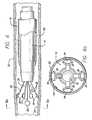
- FIG. 1is a diagram of an energy application system with a partial cutaway view of a catheter showing both the working end and the connecting end and incorporating a preferred embodiment of the present invention
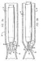
- FIG. 2is a cross-sectional view of the working end of a first embodiment of a catheter in accordance with the invention depicting the electrodes in a fully extended position;
- FIG. 2 ais an end view of the working end of the first embodiment of the catheter taken along line 2 a — 2 a of FIG. 2;
- FIG. 3is a cross-sectional view of the working end of the first embodiment depicting the electrodes in a fully retracted position
- FIG. 4is a cross-sectional view of the working end of a second catheter in accordance with principles of the invention depicting the electrodes in a fully extended position;
- FIG. 4 ais an end view of the second embodiment of the invention taken along line 4 a — 4 a of FIG. 4;
- FIG. 5is a cross-sectional view of the working end of the second embodiment of the catheter of FIG. 4 depicting the electrodes in a fully retracted position;
- FIG. 6is a cross-sectional view of an anatomical structure containing the catheter of FIG. 2 with the electrodes in apposition with the anatomical structure;
- FIG. 6 ais an end view of the anatomical structure containing the catheter taken along line 6 a — 6 a of FIG. 6;
- FIGS. 7 a through 7 care cross-sectional views of the anatomical structure containing a catheter in accordance with the first embodiment of the invention and depicting the anatomical structure at various stages of ligation;
- FIG. 8is a cross-sectional view of an anatomical structure containing a catheter in accordance with the second embodiment of the invention as depicted in FIG. 4;
- FIG. 8 ais an end view of the anatomical structure containing the catheter taken along line 8 a — 8 a of FIG. 8;
- FIGS. 9 a and 9 bare cross-sectional views of the anatomical structure containing the catheter in accordance with the second embodiment of the invention and depicting the anatomical structure at various stages of ligation;
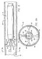
- FIG. 10is a cross-sectional view of the working end of a third embodiment of a catheter in accordance with the invention depicting the electrodes in a fully extended position;
- FIG. 10 ais an end view of the working end of the third embodiment of the catheter taken along line 10 a — 10 a of FIG. 10;
- FIG. 11is a cross-sectional view of the working end of the third embodiment depicting the electrodes in a fully retracted position
- FIG. 11 ais a view taken along line 11 a — 11 a of FIG. 11
- FIG. 12is a cross-sectional view of an anatomical structure containing the catheter of FIG. 10 with the electrodes in apposition with the anatomical structure;
- FIG. 13is a cross-sectional view of the anatomical structure containing the catheter of FIG. 10 where the anatomical structure is being ligated by the application of energy from the electrodes;
- FIG. 14is a cross-sectional view of an anatomical structure containing the catheter of FIG. 10 with the electrodes in apposition with the anatomical structure where external compression is being applied to reduce the diameter of the hollow structure before the application of energy from the electrodes to ligate the structure;
- FIG. 15is a side view of another embodiment of an electrode catheter having a balloon and a coaxial fluid channel
- FIG. 16is a partial cross-sectional view of the balloon and catheter of FIG. 15;
- FIG. 17is a cross-sectional view of an anatomical structure containing another embodiment of the catheter having a balloon and bowable arms with electrodes;
- FIG. 18is a side view of another embodiment of an electrode catheter having a covering spanning the splayed leads of the electrodes extended out the catheter;
- FIG. 19is a side view of another embodiment of an electrode catheter having a balloon and a coaxial fluid channel
- FIG. 20is a side view of another embodiment of an electrode catheter having a balloon and a coaxial fluid channel
- FIG. 21is a partial cross-sectional side view of another embodiment of an electrode catheter having an expandable section.
- FIG. 22is a partial cross-sectional side view of the embodiment of an electrode catheter of FIG. 21 in an expanded condition.
- FIG. 1shown in FIG. 1 is a catheter 10 for applying energy to an anatomical structure such as a vein.
- the catheter 10includes an outer sheath 12 having a distal orifice 14 at its working end 15 .
- the connector end 17 of the outer sheath 12is attached to a handle 16 that includes an electrical connector 18 for interfacing with a power source 22 , typically an RF generator, and a microprocessor controller 23 .
- the power source 22 and microprocessor 23are usually contained in one unit.
- the controller 23controls the power source 22 in response to external commands and data from a sensor, such as a thermocouple, located at an intraluminal venous treatment site.
- the usercan select a constant power output so that automated temperature control is not present and the user can manually adjust the power output in view of the temperature on a display readout.
- the catheter 10includes an expandable electrode device 24 (partially shown) that moves in and out of the outer sheath 12 by way of the distal orifice 14 .
- the electrode deviceincludes a plurality of electrodes which can be expanded by moving the electrodes within the shaft, or by moving the outer shaft relative to the electrodes.
- FIG. 1illustrates a plurality of electrodes surrounding a single central electrode, different electrode configurations will be described for the catheter.
- a fluid port 21communicates with the interior of the outer sheath 12 .
- the catheter 10can be periodically flushed out with saline through the port 21 .
- the flushing fluidcan travel between the outer sheath and the inner sheath.
- the portalso allows for the delivery of drug therapies. Flushing out the catheter prevents the buildup of biological fluid, such as blood, within the catheter 10 .
- the treatment area of the hollow anatomical structure such as a veincan be flushed with a fluid such as saline, or a dielectric fluid, in order to evacuate blood from the treatment area of the vein so as to prevent the formation of coagulum or thrombosis.
- the use of a dielectric fluidcan minimize unintended heating effects away from the treatment area.
- the dielectric fluidprevents the current of RF energy from flowing away from the vein wall.
- the catheter 10includes a lumen which begins at the distal tip of the outer sheath 12 and runs substantially along the axis of the outer sheath 12 before terminating at the guide-wire port 20 of the handle 16 .
- a guide wirecan be introduced through the lumen of the catheter 10 for use in guiding the catheter to the desired treatment site.
- the catheteris sized to treat smaller veins, the outer diameter of the catheter may not allow for a fluid flush between the outer sheath 12 and the inner sheath 28 . However, a fluid flush can be introduced through the lumen for the guide wire in such an embodiment.
- the outer sheath 12includes a shell 44 and a tip portion 46 .
- the tip 46is preferably tapered inward at its distal end or is “nosecone” shaped.
- the tip 46can have other shapes that facilitate tracking of the catheter 10 over a guide wire and through the bends in the venous vascular system.
- the nosecone-shaped tip 46can, for example, be fabricated from a polymer having a soft durometer, such as 70 Shore A.
- the shell 44comprises a biocompatible material having a low coefficient of friction.
- the outer sheath 12is sized to fit within a venous lumen and for example may be between 5 and 9 French, which corresponds to a diameter of between 1.7 mm (0.07 in) and 3.0 mm (1.2 in), or other sizes as appropriate.
- the electrode device 24contains a number of leads, including insulated primary leads 30 and, in some embodiments, a secondary lead 31 .
- the leadsare connected to the power source 22 (FIG. 1) such that the polarity of the leads may be switched as desired.
- a microprocessor controllercan be used to switch the polarity, as well as control other characteristics of the power for the electrode device.
- the electrode devicecan operate in either a bipolar or a monopolar configuration. When adjacent primary leads 30 have opposite polarity the electrode device 24 operates as a bipolar electrode device. When the primary leads 30 are commonly charged the electrode device 24 can operate as a monopolar electrode device.
- the electrode device 24When the primary leads 30 are commonly charged, and a secondary lead 31 has an opposite polarity, the electrode device 24 operates as a bipolar electrode device.
- the inventionis not limited to four primary leads 30 ; more or fewer leads may be used in either embodiment.
- the number of leadscan be dependent on the size or diameter of the hollow anatomical structure to be treated.
- the apposed electrodesshould be kept within a certain distance of one another. Larger vessels may require more primary leads to ensure proper current density and proper heat distribution.
- each of the leads 30 , 31may be removed at the distal end 32 , 33 to expose the conductive wire.
- the electrode 34In the first configuration as shown in FIGS. 2, 2 a, and 3 , the electrode 34 has a hemispherical shape. In a second configuration, the electrode can have either a generally spherical shape or a spoon shape. As shown in FIGS. 4, 4 a and 5 , the electrodes have a spoon shape which can be combined to form a sphere or other shape so as to minimize its profile when the vein collapses.
- the electrodes 34are either integrally formed at the distal end 32 , soldered, or otherwise formed to the distal end of each primary lead 30 .
- the distal end 32when the distal end 32 is referred to as acting as an electrode, this is not limited to where the electrode 34 is integrally formed at the distal end 32 .
- the distal endcan apply energy to the surrounding tissue where there is an electrode integrally formed at the distal end, or where an electrode is separately soldered to the distal end, or where there is another energy delivery device located at the distal end.
- the electrode 34typically has a diameter greater than the diameter of the primary lead 30 .
- the primary lead 30may have a diameter ranging from 0.18 mm (0.007 in.) to 0.28 mm (0.011 in.), while the electrode 34 has a diameter of 0.36 mm (0.014 in.) to 0.51 mm (0.020 in.).
- the primary leads 30 and the electrodes 34are preferably made from a biologically-compatible material such as stainless steel.
- the insulation surrounding the primary leads 30generally has a thickness of between 0.03 mm (0.001 in.) and 0.06 mm (0.0025 in.), resulting in a combined lead-insulation diameter of between 0.23 mm (0.009 in.) and 0.41 mm (0.016 in.).
- each primary lead 30is strip-shaped with a width from 0.76 mm (0.03 in.) to 1.0 mm (0.04 in) and a thickness of approximately 0.13 mm (0.005 in.), while the secondary lead 31 is typically tubular-shaped.
- a hemispherical electrode 34is shaped at the distal end, as for example, by sanding down a sixteenth-inch (1.6 mm) diameter sphere which is soldered to the distal end 32 of the primary lead 30 .
- the electrodescan also be constructed by stamping the desired shape or configuration from the conductive lead.
- the electrodeis integral with the lead, and the remainder of the lead is insulated.
- the distal end 33 of the secondary lead 31preferably includes a generally spherically-shaped electrode 35 .
- An alignment device 36arranges the leads 30 , 31 such that they are mounted to the catheter at only their proximal ends and so that separation is maintained between the leads within, and distal to the alignment device.
- the leadscan form cantilevers when mounted on the alignment device.
- a preferred configuration of the alignment device 36includes a plurality of off-center, axially-aligned lumina 38 which are substantially symmetrically positioned relative to the axis of the alignment device 36 .
- the alignment device 36is formed, for example, by extruding the plurality of axially-aligned lumina 38 through a solid cylinder composed of a dielectric material, such as polyamide.
- Each lead 30passes through an individual off-center lumen 38 and exits out the rear of the alignment device 36 .
- the alignment device 36may further include a central lumen 48 that may be aligned with the axis.
- the central lumen 48is used for accepting a guide wire or for the delivery or perfusion of medicant and cooling solution to the treatment area during application of RF energy.
- the central lumen 48may be used for the secondary lead 31 .
- the alignment device 36may also further include an auxiliary lumen 47 for additional leads, such as the leads of a thermocouple used as a temperature sensor.
- the alignment device 36comprises a dielectric material to prevent or minimize any coupling effect the leads 30 , 31 may have with each other and, if present, the guide wire.
- the length of the alignment deviceis, for example, 12.5 mm (0.5 in.) to 19.0 mm (0.75 in.) in one embodiment. However, these dimensions are provided for purposes of illustration and not by way of limitation.
- the inner sheath 28is attached to the alignment device 36 and extends beyond the rear 37 of the alignment device.
- the inner sheath 28completely surrounds the exterior wall of the alignment device 36 and is mounted to it by adhesive or press fit or in other manner such that it remains in a fixed position relative to the inner sheath.
- the inner sheath and alignment devicecan act as an inner member relative to the outer sheath.
- the inner sheath 28comprises a biocompatible material with a low coefficient of friction.
- the inner sheath 28provides a pathway for the interconnection between the leads 30 , 31 and the electrical connector 18 (FIG. 1 ). This interconnection may occur in any of several ways.
- the leads 30 , 31themselves may be continuous and run the entire length of the inner sheath 28 .
- the positively charged leads 30 , 31may couple with a common positively charged conductor housed in the inner sheath 28 .
- the negatively charged leads 30 , 31may couple with a common negative conductor.
- the leads 30 , 31are connected to a conductor that allows for the polarity of the leads to be switched.
- the conductormay comprise, for example, a 36 gauge copper lead with a polyurethane coating.
- the couplingmay occur at any point within the inner sheath 28 . To reduce the amount of wire contained in the catheter, it is advantageous to couple the leads 30 , 31 at the point where the leads exit the rear 37 of the alignment device 36 .
- bonding material 40surround the leads 30 , 31 at the front end of the alignment device 36 .
- the leads 30 , 31exit through the distal orifice 14 as the outer sheath 12 is retracted backwards over the alignment device 36 .
- the inwardly tapered tip 46impedes the retracting movement of the outer sheath 12 to prevent the exposure of the alignment device 36 .
- FIG. 3shows the leads 30 and 31 in the retracted position where all leads are within the nosecone-shaped tip portion 46 and the outer shell 44 .
- the alignment device 36has been moved relative to the outer shell 44 .
- the soft noseconeprovides an atraumatic tip for when the catheter is maneuvered through the tortuous venous system.
- the electrode at the distal end of the secondary lead 31can be sized to approximately the same size as the opening formed in the nosecone 46 .
- the noseconeforms a closed atraumatic tip together with the electrode of the secondary lead when the alignment device is retracted into the outer sheath of the catheter. This can present an atraumatic tip even where the nosecone is not constructed from a material having a soft durometer.
- the alignment device 36is attached to the outer sheath 12 and thereby remains immobile in relation to it.
- the inner sheath 28is movably positioned at the rear of the alignment device 36 and again provides a pathway for the interconnection between the primary leads 30 and the electrical connector 18 (FIG. 1 ).
- the inner sheath 28contains a guide-wire tube 49 that runs the entire length of the inner sheath.
- the guide-wire tube 49is aligned to communicate with the central lumen 48 of the alignment device 36 at one end and with the guide-wire port 20 (FIG. 1) at the other end.
- the primary leads 30may be continuous and run the entire length of the inner sheath 28 or they may be coupled to common leads as previously described.
- the primary leads 30are secured to the front end 27 of the inner sheath 28 , as for example with a potting material 50 , so that the movement of the inner sheath 28 results in a corresponding movement of the primary leads 30 through the lumina 38 of the alignment device 36 .
- the primary leads 30are not secured to the alignment device 36 and in essence are free-floating leads in the axial direction.
- the primary leads 30travel through the alignment device 36 and exit through the distal orifice 14 as the front end of the inner sheath 28 is moved toward the rear 37 of the alignment device 36 .
- the primary leads 30are formed, e.g., arced or bent, to move away from each other and thereby avoid contact.
- the “distal portion” of the primary leads 30is the portion of the lead which extends from the front end of the alignment device 36 when the leads are fully extended through the distal orifice 14 . It is preferred that the distal portions 42 are formed to move radially outward from each other relative to the axis of the alignment device 36 and form a symmetrical arrangement. This is shown in both the embodiments of FIG. 2 a and FIG. 4 a.
- the degree of arc or bend in the primary leads 30may be any that is sufficient to radially expand the leads as they exit the outer sheath 12 through the distal orifice 14 .
- the electrodesare preferably partially embedded in the vein wall to assure full contact.
- the rounded portion of the electrodeis embedded into the vein wall to achieve full surface apposition so that the entire uninsulated surface area of the electrode is in contact with venous tissue for effective current distribution.
- the surface area of the electrodes in contact with the venous tissuepreferably is sufficient to avoid a high current density which may lead to spot heating of the venous tissue.
- the heating effectis preferably distributed along a circumferential band of the vein.
- the apposed electrodesshould be spaced no more than 4 or 5 millimeters from one another along the circumference of the vein.
- the electrode arrangementis related to the size or diameter of the vein being treated.
- Other properties of the primary leads 30such as lead shape and insulation thickness, affect the push force of the lead and the degree of arc or bend must be adjusted to compensate for these factors.
- a wire having a diameter of between 0.18 mm (0.007 in) and 0.28 mm (0.011 in) with a total insulation thickness of between 0.05 mm (0.002 in) to 0.13 mm (0.005 in)is arced or bent at an acute angle to provide sufficient apposition with the anatomical structure. It is to be understood that these dimensions are provided for illustrative purposes, and not by way of limitation.
- the leadsmay be straight but are mounted in the alignment device at an angle such that they are normally directed outward.
- the primary leads 30be strip-shaped, that is rectangular in cross section, with dimensions, for example, of a width from 0.76 mm (0.030 in.) to 1.0 mm (0.039 in) and a thickness of approximately 0.13 mm (0.005 in.).
- the rectangular cross sectionprovides increased resistance to bending in the width dimension but allows bending more freely in the thickness dimension.
- This strip-shaped configuration of the primary leads 30is shown in FIGS. 2, 2 a, and 3 and provides for increased stability in the lateral direction while allowing the necessary bending in the radial direction. In FIGS.
- each primary leadcomprises a rectangular cross section mounted in relation to the catheter such that the thinner dimension of the rectangular cross section is aligned with the direction of expansion of the lead.
- the leadsare less likely to bend sideways when expanded outward, and a uniform spacing between leads is more assured. Uniform spacing promotes uniform heating around the venous tissue which is in apposition with the electrodes at the distal ends of the leads.
- the length of the distal portion of the leads 30also affects the configuration of the electrode device 24 .
- the maximum distance between two mutually opposed electrodes 34i.e., the effective diameter of the electrode device 24 , is affected by the bend degree and length of the distal portion 42 .
- the longer the length of the distal portion 42the greater the diameter of the electrode device 24 . Accordingly, by changing the distal portion 42 length and arc or bend degree, the catheter 10 can be configured for use in differently sized anatomical structures.
- leads 30 , 31can be employed with the catheter.
- the number of leads 30 , 31is limited by the diameter of the alignment device 36 and the number of lumina 36 , 38 , 47 that can be extruded through the alignment device.
- an even number of primary leads 30are preferably available to form a number of oppositely charged electrode pairs.
- the electrodes in apposition with the anatomical structureshould be maintained within a certain distance of each other.
- any number of commonly charged leads 30can be present.
- distribution of RF energy through the anatomical tissueis obtained by creating a return path for current through the tissue by providing a return device at a point external from the tissue, such as a large metal pad.
- an actuator 25controls the extension of the electrode device 24 through the distal orifice 14 .
- the actuator 25may take the form of a switch, lever, threaded control knob, or other suitable mechanism, and is preferably one that can provide fine control over the movement of the outer sheath 12 or the inner sheath 28 , as the case may be.
- the actuator 25(FIG. 1) interfaces with the outer sheath 12 (FIG. 2, 2 a and 3 ) to move it back and forth relative to the inner sheath 28 .
- the actuator 25(FIG. 1) interfaces with the inner sheath 28 (FIGS. 4, 4 a and 5 ) to move it back and forth relative to the outer sheath 12 .
- the relative position between the outer sheath and inner sheathis thus controlled, but other control approaches may be used.
- the catheter 10includes a temperature sensor 26 , such as a thermocouple.
- the temperature sensor 26is mounted in place on an electrode 34 so that the sensor 26 is nearly or is substantially flush with the exposed surface of the electrode 34 .
- the sensor 26is shown in the drawings as protruding from the electrodes for clarity of illustration only.
- the sensor 26senses the temperature of the portion of the anatomical tissue that is in apposition with the exposed electrode surface. Monitoring the temperature of the anatomical tissue provides a good indication of when shrinkage of the tissue is ready to begin.
- a temperature sensor 26 placed on the electrode facing the anatomical tissueprovides an indication of when shrinkage occurs (70° C.
- the temperature sensor 26interfaces with the controller 23 (FIG. 1) through a pair of sensor leads 45 which preferably run through the auxiliary lumen 47 and then through the inner sheath 28 .
- the signals from the temperature sensor 26are provided to the controller 23 which controls the magnitude of RF energy supplied to the electrodes 34 in accordance with the selected temperature criteria and the monitored temperature.
- Impedancecan be used to detect the onset of coagulum formation.
- the catheterin the operation of one embodiment of the catheter 10 , the catheter is inserted into a hollow anatomical structure, such as a vein 52 .
- the catheteris similar to the embodiment discussed in connection with FIGS. 2 and 3.
- the catheter 10further includes an external sheath 60 through which a fluid can be delivered to the treatment site.
- the fluid port(not shown) communicates with the interior of the external sheath 60 , and fluid is delivered from between the external sheath 60 and the outer sheath 12 .
- the external sheath 60surrounds the outer sheath 12 to form a coaxial channel through which fluid may be flushed.
- Fluoroscopy, ultrasound, an angioscope imaging technique, or other techniquemay be used to direct the specific placement of the catheter and confirm the position in the vein.
- the actuator(not shown) is then operated to shift the outer sheath relative to the inner sheath by either retracting the outer sheath 12 backward or advancing the inner sheath 28 forward to expose the leads 30 , 31 through the distal orifice 14 .
- the primary leads 30expand radially outward relative to the axis of the alignment device 36 , while the secondary lead 31 remains substantially linear.
- the primary leads 30continue to move outward until apposition with the vein wall 54 occurs and the outward movement of the primary leads 30 is impeded.
- the primary leads 30contact the vein along a generally circumferential band of the vein wall 54 . This outward movement of the primary leads 30 occurs in a substantially symmetrical fashion. As a result, the primary-lead electrodes 34 are substantially evenly spaced along the circumferential band of the vein wall 54 . The central-lead electrode 35 is suspended within the vein 52 without contacting the vein wall 54 .
- the power supply 22is activated to provide suitable RF energy.
- suitable frequencyis 510 kHz.
- One criterion used in selecting the frequency of the energy to be appliedis the control desired over the spread, including the depth, of the thermal effect in the venous tissue. Another criterion is compatibility with filter circuits for eliminating RF noise from thermocouple signals.
- the primary leads 30are initially charged such that adjacent leads are oppositely charged while the secondary lead is electrically neutral. These multiple pairs of oppositely charged leads 30 form active electrode pairs to produce an RF field between them.
- discrete RF fieldsare set up along the circumferential band of the vein wall 54 . These discrete fields form a symmetrical RF field pattern along the entire circumferential band of the vein wall 54 , as adjacent electrodes 34 of opposite polarity produce RF fields between each other.
- a uniform temperature distributioncan be achieved along the vein wall being treated.
- the RF energyis converted within the adjacent venous tissue into heat, and this thermal effect causes the venous tissue to shrink, reducing the diameter of the vein.
- a uniform temperature distribution along the vein wall being treatedavoids the formation of hot spots in the treatment area while promoting controlled uniform reduction in vein diameter.
- the thermal effectproduces structural transfiguration of the collagen fibrils in the vein.
- the collagen fibrilsshorten and thicken in cross-section in response to the heat from the thermal effect.
- the energycauses the vein wall 54 to collapse around the primary-lead electrodes 34 .
- the wall 54continues to collapse until further collapse is impeded by the electrodes 34 .
- the electrodesare pressed farther and farther together by the shrinking vein wall 54 until they touch and at that point, further collapse or ligation of the wall 54 is impeded.
- the polarity of the primary-lead electrodesis switched so that all primary-lead electrodes are commonly charged.
- the switching of polarity for the leadsneed not be instantaneous.
- the application of RF energycan be ceased, the polarity switched, and then RF energy is applied again at the switched polarity.
- the secondary-lead electrode 35is then charged so that its polarity is opposite that of the primary-lead electrodes 34 .
- the RF fieldis set up between the primary-lead electrodes 34 and the secondary-lead electrode 35 .
- the catheter 10is then pulled back while energy is applied to the electrode device.
- the primary-lead electrodes 34remain in apposition with the vein wall 54 while the secondary-lead electrode 35 comes in contact with the portion of the vein wall previously collapsed by the primary-lead electrodes 34 .
- RF energypasses through the vein wall 54 between the primary-lead electrodes 34 and the secondary-lead electrode 35 and the vein wall continues to collapse around the secondary-lead electrode 35 as the catheter 10 is being retracted.
- ligation in accordance with this methodresults in an occlusion along a length of the vein 52 .
- a lengthy occlusionas opposed to an acute occlusion, is stronger and less susceptible to recanalization.
- the catheter 10 having both primary and secondary leadsis operated in a monopolar manner.
- the secondary-lead electrode 35remains neutral, while the primary leads 30 are commonly charged and act in conjunction with an independent electrical device, such as a large low-impedance return pad (not shown) placed in external contact with the body, to form a series of discrete RF fields.
- a large low-impedance return pad(not shown) placed in external contact with the body, to form a series of discrete RF fields.
- These RF fieldsare substantially evenly spaced around the circumference of the vein and travel along the axial length of the vein wall causing the vein wall to collapse around the primary-lead electrodes.
- the secondary-lead electrodeUpon collapse of the vein wall, the secondary-lead electrode is charged to have the same polarity as that of the primary-lead electrodes. The electrode device is retracted and the vein wall collapses as described in the bipolar operation.
- the application of RF energyis substantially symmetrically distributed through the vein wall, regardless of the diameter of the vein 52 .
- This symmetrical distribution of RF energyincreases the predictability and uniformity of the shrinkage and the strength of the occlusion.
- the uniform distribution of energyallows for the application of RF energy for a short duration and thereby reduces or avoids the formation of heat-induced coagulum on the electrodes 34 .
- the leads, including the non-convex outer portion of the electrode,are insulated to further prevent heating of the surrounding blood.
- Fluidcan be delivered before and during RF heating of the vein being treated through a coaxial channel formed between the external sheath 60 and the outer sheath 12 . It is to be understood that another lumen can be formed in the catheter to deliver fluid to the treatment site.
- the delivered fluiddisplaces or exsanguinates blood from the vein so as to avoid heating and coagulation of blood. Fluid can continue to be delivered during RF treatment to prevent blood from circulating back to the treatment site.
- the delivery of a dielectric fluidincreases the surrounding impedance so that RF energy is directed into the tissue of the vein wall.
- FIGS. 8, 8 a, 9 a and 9 bin the operation of an alternate embodiment of the catheter 10 that may be used with a guide wire 53 .
- the catheter 10is inserted into a hollow anatomical structure, such as a vein 52 .
- the guide wire 53is advanced past the point where energy application is desired.
- the catheter 10is then inserted over the guide wire 53 by way of the central lumen 48 and the guide wire tube 49 (FIG. 4) and is advanced over the guide wire through the vein to the desired point.
- the guide wire 53is typically pulled back or removed before RF energy is applied to the electrode device 24 .
- the actuator 25(FIG. 1) is then manipulated to either retract the outer sheath 12 backward, or advance the inner sheath 28 forward to expose the leads 30 through the distal orifice 14 .
- the leads 30exit the distal orifice 14 and expand radially outward relative to the axis of the alignment device 36 .
- the leads 30continue to move outward until apposition with the vein wall 54 occurs.
- the leads 30contact the vein along a generally circumferential band of the vein wall 54 . This outward movement of the leads occurs in a substantially symmetrical fashion.
- the electrodes 34are substantially evenly spaced along the circumferential band of the vein wall 54 .
- the electrodescan be spaced apart in a staggered fashion such that the electrodes do not lie along the same plane.
- adjacent electrodescan extend different lengths from the catheter so that a smaller cross-sectional profile is achieved when the electrodes are collapsed toward one another.
- the power supply 22is activated to provide suitable RF energy to the electrodes 34 so that the catheter 10 operates in either a bipolar or monopolar manner as previously described.
- the energycauses the vein wall 54 to collapse around the electrodes 34 causing the leads to substantially straighten and the electrodes to cluster around each other.
- the wall 54continues to collapse until further collapse is impeded by the electrodes 34 (FIG. 9 b ).
- the application of energymay cease.
- the electrodescan be configured to form a shape with a reduced profile when collapsed together.
- the electrodescan also be configured and insulated to continue applying RF energy after forming a reduced profile shape by the collapse of the vein wall.
- the catheter 10can be pulled back to ligate the adjacent venous segment. If a temperature sensor 26 is included, the application of energy may cease prior to complete collapse if the temperature of the venous tissue rises above an acceptable level as defined by the controller 23 .
- fluidcan be delivered before and during RF heating of the vein being treated.
- the fluidcan displace blood from the treatment area in the vein to avoid the coagulation of blood.
- the fluidcan be a dielectric medium.
- the fluidcan include an anticoagulant such as heparin which can chemically discourage the coagulation of blood at the treatment site.
- the actuator mechanismcauses the primary leads to return to the interior of the outer sheath 12 .
- Either the outer sheath or the inner sheathis moved to change the position of the two elements relative to one another.
- the catheter 10may be moved to another venous section where the ligation process is repeated.
- the catheter 10is removed from the vasculature. The access point of the vein is then sutured closed, or local pressure is applied until bleeding is controlled.
- the inner member or sheath 28is contained within the outer sheath 12 .
- the inner sheathis preferably constructed from a flexible polymer such as polyimide, polyethylene, or nylon, and can travel the entire length of the catheter. The majority of the catheter should be flexible so as to navigate the tortuous paths of the venous system.
- a hypotube having a flared distal end 33 and a circular cross-sectional shapeis attached over the distal end of the inner sheath 28 .
- the hypotubeis preferably no more than about two to three centimeters in length.
- the hypotubeacts as part of the conductive secondary lead 31 .
- An uninsulated conductive electrode sphere 35is slipped over the hypotube.
- the flared distal end of the hypotubeprevents the electrode sphere from moving beyond the distal end of the hypotube.
- the sphereis permanently affixed to the hypotube, such as by soldering the sphere both front and back on the hypotube.
- the majority or the entire surface of the spherical electrode 35remains uninsulated.
- the remainder of the hypotubeis preferably insulated so that the sphere-shaped distal end can act as the electrode.
- the hypotubecan be covered with an insulating material such as a coating of parylene.
- the interior lumen of the hypotubeis lined by the inner sheath 28 which is attached to the flaired distal end of the hypotube by adhesive such as epoxy.
- a plurality of primary leads 30Surrounding the secondary lead 31 and sphere-shaped electrode 35 are a plurality of primary leads 30 which preferably have a flat rectangular strip shape and can act as arms. As illustrated in FIG. 11, the plurality of primary leads are preferably connected to common conductive rings 62 . This configuration maintains the position of the plurality of primary leads, while reducing the number of internal electrical connections.
- the rings 62are attached to the inner sheath 28 . The position of the rings and the primary leads relative to the outer sheath follows that of the inner sheath. As earlier described, the hypotube of the secondary lead 31 is also attached to the inner sheath 28 . Two separate conductive rings can be used so that the polarity of different primary leads can be controlled separately.
- adjacent primary leadscan be connected to one of the two separate conductive rings so that the adjacent leads can be switched to have either opposite polarities or the same polarity.
- the ringsare preferable spaced closely together, but remain electrically isolated from one another along the inner sheath. Both the rings and the hypotube are coupled with the inner sheath, and the primary leads 30 that are connected to the rings move together with and secondary lead while remaining electrically isolated from one another. Epoxy or another suitable adhesive can be used to attach the rings to the inner sheath.
- the primary leads from the respective ringseach alternate with each other along the circumference of the inner sheath. The insulation along the underside of the leads prevents an electrical short between the rings.
- the ring and primary leadsare attached together to act as cantilevers where the ring forms the base and the rectangular primary leads operate as the cantilever arms.
- the leads 30are connected to the ring and are formed to have an arc or bend such that the leads act as arms which tend to spring outwardly away from the catheter and toward the surrounding venous tissue. Insulation along the underside of the leads and the rings prevents unintended electrical coupling between the leads and the opposing rings.
- the leadsare formed straight and connected to the ring at an angle, such that the leads tend to expand or spring radially outward from the ring. The angle at which the leads are attached to the ring should be sufficient to force the primary distal ends and electrodes 34 through blood and into apposition with the vein wall.
- the rectangular cross section of the leads 30can provide increased stability in the lateral direction while allowing the necessary bending in the radial direction.
- the leads 30are less likely to bend sideways when expanded outward, and a uniform spacing between leads is more assured. Uniform spacing between the leads 30 and the distal ends promotes uniform heating around the vein by the electrodes 34 .
- the distal ends of the primary leads 30are uninsulated to act as electrodes 34 having a spoon or hemispherical shape.
- the leadscan be stamped to produce an integral shaped electrode at the distal end of the lead.
- the uninsulated outer portion of the distal end electrode 34 which is to come into apposition with the wall of the anatomical structureis preferably rounded and convex.
- the flattened or non-convex inner portion of the distal endis insulated to minimize any unintended thermal effect, such as on the surrounding blood in a vein.
- the distal end electrodes 34are configured such that when the distal ends are forced toward the inner sheath 12 , as shown in FIG. 10 a, the distal ends combine to form a substantially spherical shape with a profile smaller than the profile for the spherical electrode 35 at the secondary distal end.
- the outer sheath 12can slide over and surround the primary and secondary leads 30 , 31 .
- the outer sheath 12includes an orifice which is dimensioned to have approximately the same size as the spherical electrode 35 at the secondary distal end which functions as an electrode. A close or snug fit between the electrode 35 at the secondary distal end and the orifice of the outer sheath 12 is achieved. This configuration provides an atraumatic tip for the catheter.
- the electrode 35 secondary distal endis preferably slightly larger than the orifice.
- the inner diameter of the outer sheath 12is approximately the same as the reduced profile of the combined primary distal end electrodes 34 .
- the diameter of the reduced profile of the combined primary distal end electrodes 34is preferably less than the inner diameter of the outer sheath.
- a fluid portcan communicate with the interior of the outer sheath 12 so that fluid can be flushed between the outer sheath 12 and the inner sheath 28 .
- a fluid portcan communicate with a central lumen 48 in the hypotube which can also accept a guide wire.
- the catheter 10can be periodically flushed with saline which can prevent the buildup of biological fluid, such as blood, within the catheter 10 .
- a guide wirecan be introduced through the lumen 48 for use in guiding the catheter to the desired treatment site.
- a fluidcan be flushed or delivered though the lumen as well. If a central lumen is not desired, the lumen of the hypotube can be filled with solder.
- the primary leads 30 and the connecting ringsare connected to a power source 22 such that the polarity of the leads may be switched as desired.
- the electrode device 24to operate in either a bipolar or a monopolar configuration.
- a bipolar electrode operationis available.
- a monopolar electrode operationis available in combination with a large return electrode pad placed in contact with the patient.
- a secondary lead 31has an opposite polarity
- a bipolar electrode operationis available. More or fewer leads may be used. The number of leads can be dependent on the size or diameter of the hollow anatomical structure to be treated.
- the catheter 10can include a temperature sensor, such as a thermocouple, mounted in place on the distal end or electrode 34 so that the sensor is substantially flush with the exposed surface of the electrode 34 .
- the sensorsenses the temperature of the portion of the anatomical tissue that is in apposition with the exposed electrode surface.
- Application of the RF energy from the electrodes 34is halted or reduced when the monitored temperature reaches or exceeds the specific temperature that was selected by the operator, such as the temperature at which anatomical tissue begins to cauterize.
- the catheterin the operation of one embodiment of the catheter 10 , the catheter is inserted into a hollow anatomical structure, such as a vein. Fluoroscopy, ultrasound, an angioscope imaging technique, or another technique may be used to direct and confirm the specific placement of the catheter in the vein.
- the actuatoris then operated to retract the outer sheath 12 to expose the leads 30 , 31 . As the outer sheath no longer restrains the leads, the primary leads 30 move outward relative to the axis defined by the outer sheath, while the secondary lead 31 remains substantially linear along the axis defined by the outer sheath.
- the primary leads 30continue to move outward until the distal end electrode 34 of the primary leads are placed in apposition with the vein wall 54 occurs and the outward movement of the primary leads 30 is impeded.
- the primary leads 30contact the vein along a generally circumferential area of the vein wall 54 . This outward movement of the primary leads 30 occurs in a substantially symmetrical fashion so that the primary distal end electrodes 34 are substantially evenly spaced.
- the central-lead electrode 35is suspended within the vein without contacting the vein wall 54 .
- the power supply 22is activated to provide suitable RF energy.
- the primary leads 30are initially charged such that adjacent leads are oppositely charged while the secondary lead is electrically neutral.
- These multiple pairs of oppositely charged leads 30form active electrode pairs to produce an RF field between them, and form a symmetrical RF field pattern along a circumferential band of the vein wall to achieve a uniform temperature distribution along the vein wall being treated.
- the RF energyproduces a thermal effect which causes the venous tissue to shrink, reducing the diameter of the vein.
- the energycauses the vein wall 54 to collapse until further collapse is impeded by the electrodes 34 .
- the electrodesare pressed closer together by the shrinking vein wall.
- the electrodes 34are pressed together to assume a reduced profile shape which is sufficiently small so that the vein is effectively ligated.
- the polarity of the primary-lead electrodesis switched so that all of the primary-lead electrodes are commonly charged.
- the secondary-lead electrode 35is then charged so that its polarity is opposite that of the primary-lead electrodes 34 .
- the electrode at the distal end of the secondary leadcan also come into contact with the a portion of the vein wall so that an RF field is created between the primary electrodes 34 and the secondary electrode 35 .
- the catheter 10is pulled back to ensure apposition between the electrodes at the distal ends of the leads and the vein wall.
- the primary-lead electrodes 34remain in apposition with the vein wall 54 while the secondary-lead electrode 35 comes in contact with the portion of the vein wall previously collapsed by the primary-lead electrodes 34 .
- RF energypasses through the venous tissue between the primary-lead electrodes 34 and the secondary-lead electrode 35 .
- Ligation as the catheter is being retractedproduces a lengthy occlusion which is stronger and less susceptible to recanalization than an acute point occlusion.
- the secondary-lead electrode 35In a monopolar operation, the secondary-lead electrode 35 remains neutral, while the primary leads 30 are commonly charged and act in conjunction with an independent electrical device, such as a large low-impedance return pad (not shown) placed in external contact with the body, to form RF fields substantially evenly spaced around the circumference of the vein.
- an independent electrical devicesuch as a large low-impedance return pad (not shown) placed in external contact with the body, to form RF fields substantially evenly spaced around the circumference of the vein.
- the thermal effect produced by those RF fields along the axial length of the vein wallcauses the vein wall to collapse around the primary-lead electrodes.
- the secondary-lead electrodeUpon collapse of the vein wall, the secondary-lead electrode is charged to have the same polarity as that of the primary-lead electrodes. The electrode device is retracted as described in the bipolar operation.
- the application of RF energyis substantially symmetrically distributed through the vein wall.
- the electrodesshould be spaced no more than 4 or 5 millimeters apart along the circumference of the vein, which defines the target vein diameter for a designed electrode catheter. Where the electrodes are substantially evenly spaced in a substantially symmetrical arrangement, and the spacing between the electrodes is maintained, a symmetrical distribution of RF energy increases the predictability and uniformity of the shrinkage and the strength of the occlusion.
- an external tourniquetsuch as an elastic compressive wrap or an inflatable bladder with a window transparent to ultrasound, is used to compress the anatomy, such as a leg, surrounding the structure to reduce the diameter of the vein.
- the compressive force being applied by the tourniquetmay effectively ligate the vein, or otherwise occlude the vein by flattening the vein, for certain veins, this compressive force will not fully occlude the vein.
- a fixed diameter electrode catheter in this instancewould not be effective.
- the electrodes 34 which are expanded outward by the formed leads 30can accommodate this situation.
- the reduction in vein diameterassists in pre-shaping the vein to prepare the vein to be molded to a ligated state.
- the use of an external tourniquetalso exsanguinates the vein and blood is forced away from the treatment site. Coagulation of blood during treatment can be avoided by this procedure. Energy is applied from the electrodes to the exsanguinated vein, and the vein is molded to a sufficiently reduced diameter to achieve ligation. The external tourniquet can remain in place to facilitate healing.
- the cathetercan be pulled back during the application of RF energy to ligate an extensive section of a vein. In doing so, instead of a single point where the diameter of the vein has been reduced, an extensive section of the vein has been painted by the RF energy from the catheter. Retracting the catheter in this manner produces a lengthy ***occlusion which is less susceptible to recanalization.
- the combined use of the primary and secondary electrodescan effectively produce a reduced diameter along an extensive length of the vein.
- the cathetercan be moved while the tourniquet is compressing the vein, of after the tourniquet is removed.
- fluidcan be delivered to the vein before RF energy is applied to the vein.
- the delivered fluiddisplaces blood from the treatment site to ensure that blood is not present at the treatment site, even after the tourniquet compresses the vein.
- an ultrasound transduceris used to monitor the flattening or reduction of the vein diameter from the compressive force being applied by the inflating bladder.
- the windowcan be formed from polyurethane, or a stand-off of gel contained between a polyurethane pouch.
- a gelcan be applied to the window to facilitate ultrasound imaging of the vein by the transducer.
- Ultrasound visualization through the windowallows the operator to locate the desired venous treatment area, and to determine when the vein has been effectively ligated or occluded. Ultrasound visualization assists in monitoring any pre-shaping of the vein in preparation of being molded into a ligated state by the thermal effect produced by the RF energy from the electrodes.
- the actuatorAfter completing the procedure for a selected venous section, the actuator causes the leads 30 to return to the interior of the outer sheath 12 . Once the leads 30 are within the outer sheath 12 , the catheter 10 may be moved to another venous section where the ligation process is repeated.
- a balloon 64is located on the catheter, and can be inflated through ports 66 to occlude the vein.
- the inflated balloonobstructs blood flow and facilitates the infusion of a high-impedance fluid to the vein in order to reduce the occurrence of coagulation by directing the energy into the vein wall.
- the inflation of the balloon to occlude the vein before the application of energycan obviate the use of the tourniquet to occlude the vein.
- thisalso allows the vein to be occluded even for the deep veins where a compressive tourniquet may not be able to compress the vein to occlusion. It is to be understood that other mechanisms can be used to expand the diameter of the catheter to create an impermeable barrier that occludes the vein.
- Fluid 61can be delivered after inflation of the balloon 64 and before the RF heating of the vein being treated through a coaxial channel 62 formed between the external sheath 60 and the outer sheath 12 .
- another lumencan be formed in the catheter to deliver fluid to the treatment site.
- the lumen through which the guide wire is passedmay be used for the delivery of fluid.
- the delivered fluiddisplaces or exsanguinates the remaining blood from the treatment area of the vein so as to avoid heating and coagulation of blood. Fluid can continue to be delivered during RF treatment to prevent blood from circulating back to the treatment site.
- the delivery of a high-dielectric fluidincreases the surrounding impedance so that RF energy is directed into the tissue of the vein wall.
- the vein wallcan reach the desired temperature more rapidly than in the case where energy is permitted to reach the blood, which has a cooling effect. Additionally, blood clotting is avoided with this approach, because the blood has been replaced with another fluid such as deionized water mixed with heparin to displace blood and prevent the formation of blood clots.
- FIG. 16A partial cross-sectional view of this embodiment is shown in FIG. 16, where an inflation sheath 70 surrounds the external sheath 60 to provide a coaxial inflation lumen 72 for the balloon 64 .
- the inflation lumen 72is in fluid communication with the ports 66 .
- Saline or any other suitable fluidcan be used to inflate the balloon.
- the balloon 64can be used in combination with bowable members or arms 76 having electrodes, where perfusion holes 78 are formed in the catheter between the balloon 64 and the bowable arms 76 .
- the balloon 64 in this embodimentis inflated through a balloon inflation lumen 72 .
- the use of bowable arms for treating veinsis discussed in U.S. patent application Ser. No. 08/610,911, which is hereby incorporated by reference.
- the armscan be constructed so as to spring radially outward from the catheter, yet offer little resistance in moving back toward the catheter as-the vein diameter is diminished to occlusion.
- An anti-coagulant or saline or a high-impedance fluidcan be introduced or flushed through the perfusion holes 78 in the catheter. As discussed earlier, the high-impedance fluid forces blood away from the venous treatment area and prevents the energy from being dissipated in a more conductive medium such as blood.
- a flexible covering 80is wrapped around or inside the leads 30 of the electrodes 34 to prevent blood flow in the vein.
- the covering 80spans the area between the splayed leads along the circumference of the catheter when the leads are extended out the opening, such that the webbed covering blocks blood flow within the vein.
- the coveringmay be thought of as webbing or an umbrella to keep blood on one side away from the electrodes.
- the gap, if any, between the electrodes 34 and the covering 80should be eliminated or toherwise minimized.
- the covering 80should be impermeable to fluid. Suitable materials include PET and nylon.
- Elastomeric materialsare also suitable as the leads will need to move close together as they are retracted, and interference with the movement of the leads as the vein diameter is reduced by the application of energy is preferably minimized.
- this embodimentis illustrated with only primary leads, it is to be understood that this embodiment is not so limited and that a secondary lead may be included with the catheter as well without affecting the use of the covering.
- the coveringoccludes the vein before the application of energy, such that the need for an external compressive tourniquet is not required to stop blood flow. Furthermore, this also allows the vein to be occluded even for the deep veins where a compressive tourniquet may not be able to compress the vein to occlusion.
- a high-impedance fluidsuch as deionized water, or an anti-coagulant such as heparin or saline, or both, or heparin with deionized water may be infused or flushed thorugh the perfusion holes 78 before the application of energy as well.
- the electrodesextend through the shaft lumen which also acts as a conduit for the fluid being flushed through the perfusion holes 78 .
- a sclerosing fluidmay also be delivered to the venous treatment site to enhance the ligation effect from the application of RF energy. The sclerosing fluid may be added in addition to, or in substitution of, the previously discussed fluids.
- a covering 80 having a parachute shapecan be orientated so that blood becomes trapped by the concave portion of the covering and the volume of the blood maintains the deployment of the covering.
- the coveringis a balloon having openings 84 which allow blood to gather in the balloon, and expand the balloon.
- the covering 80can be permanently attached to the catheter shaft. The catheter can still be moved along the vein, even with the balloon in an inflated state.
- the covering 80is coupled to an outer cannula 82 surrounding the catheter shaft and connected to an actuation mechanism or lever.
- the outer cannula 82can be slid along the longitudinal axis of the catheter to allow one end of the parachute covering 80 to be moved axially along the catheter shaft.
- the movable end of the coveringis pulled away from the connecting end of the catheter to collapse the covering against the catheter.
- the cannulais slid toward the working end to deploy the covering which then fills with blood entering thorugh the openings 84 , thereby occluding the vein.
- the coveringexpands as it fills with blood, and when the covering comes into contact with the vein wall, the vein is occluded.
- Fluidas before, can be infused either through perfusion holes 78 or a coaxial channel.
- the catheter 10includes an expandable section having a skeleton 90 disposed along a portion of the working end of the catheter.
- the skeleton 90is more flexible than the surrounding shaft of the catheter, and can be constructed from a metal or polymer braid.
- a flexible membrane 92covers the skeleton 90 , with the ends of the membrane attached to the shaft of the catheter adjacent the skeleton.
- the membraneis preferably constructed from an elastomeric material.
- FIG. 22when the tip of the connecting end is moved toward the working end of the catheter, or vice versa, the skeleton 90 is deformed and forces the membrane 92 out into contact with the vein wall.
- This embodimentdoes not require a separate lumen to provide an inflation fluid to a balloon.
- the skeleton 90is preferably resilient so that it returns to its original shape once the working end and connecting end are no longer being forced toward one another.
- Mechanisms for moving the connecting end toward the working end of the catheter for expanding the diameter of a catheterare also discussed in U.S. patent application Ser. No. 08/610,911, which has been incorporated by reference.
- the exapandable sectionmay be controlled separately from the extension of the electrodes, the expandable section can be controlled by the same mechanism which extends the electrodes away from the catheter.
Landscapes
- Health & Medical Sciences (AREA)
- Surgery (AREA)
- Life Sciences & Earth Sciences (AREA)
- Engineering & Computer Science (AREA)
- Heart & Thoracic Surgery (AREA)
- Medical Informatics (AREA)
- Otolaryngology (AREA)
- Plasma & Fusion (AREA)
- Physics & Mathematics (AREA)
- Biomedical Technology (AREA)
- Cardiology (AREA)
- Nuclear Medicine, Radiotherapy & Molecular Imaging (AREA)
- Molecular Biology (AREA)
- Animal Behavior & Ethology (AREA)
- General Health & Medical Sciences (AREA)
- Public Health (AREA)
- Veterinary Medicine (AREA)
- Surgical Instruments (AREA)
- Media Introduction/Drainage Providing Device (AREA)
- Materials For Medical Uses (AREA)
Abstract
Description
Claims (12)
Priority Applications (2)
| Application Number | Priority Date | Filing Date | Title |
|---|---|---|---|
| US09/497,099US6398780B1 (en) | 1997-09-11 | 2000-02-03 | Expandable vein ligator catheter and method of use |
| US10/162,057US7041098B2 (en) | 1997-09-11 | 2002-06-03 | Expandable vein ligator catheter and method of use |
Applications Claiming Priority (3)
| Application Number | Priority Date | Filing Date | Title |
|---|---|---|---|
| US08/927,251US6200312B1 (en) | 1997-09-11 | 1997-09-11 | Expandable vein ligator catheter having multiple electrode leads |
| US08/958,766US6165172A (en) | 1997-09-11 | 1997-10-26 | Expandable vein ligator catheter and method of use |
| US09/497,099US6398780B1 (en) | 1997-09-11 | 2000-02-03 | Expandable vein ligator catheter and method of use |
Related Parent Applications (1)
| Application Number | Title | Priority Date | Filing Date |
|---|---|---|---|
| US08/958,766DivisionUS6165172A (en) | 1997-09-11 | 1997-10-26 | Expandable vein ligator catheter and method of use |
Related Child Applications (1)
| Application Number | Title | Priority Date | Filing Date |
|---|---|---|---|
| US10/162,057DivisionUS7041098B2 (en) | 1997-09-11 | 2002-06-03 | Expandable vein ligator catheter and method of use |
Publications (1)
| Publication Number | Publication Date |
|---|---|
| US6398780B1true US6398780B1 (en) | 2002-06-04 |
Family
ID=27129940
Family Applications (6)
| Application Number | Title | Priority Date | Filing Date |
|---|---|---|---|
| US09/138,808Expired - LifetimeUS6401719B1 (en) | 1997-09-11 | 1998-08-21 | Method of ligating hollow anatomical structures |
| US09/497,278Expired - Fee RelatedUS6689126B1 (en) | 1997-09-11 | 2000-02-03 | Expandable vein ligator catheter and method of use |
| US09/497,099Expired - LifetimeUS6398780B1 (en) | 1997-09-11 | 2000-02-03 | Expandable vein ligator catheter and method of use |
| US10/162,057Expired - Fee RelatedUS7041098B2 (en) | 1997-09-11 | 2002-06-03 | Expandable vein ligator catheter and method of use |
| US10/164,928AbandonedUS20020148476A1 (en) | 1997-09-11 | 2002-06-07 | Method of ligating hollow anatomical structures |
| US10/775,841AbandonedUS20040162555A1 (en) | 1997-09-11 | 2004-02-09 | Expandable vein ligator catheter and method of use |
Family Applications Before (2)
| Application Number | Title | Priority Date | Filing Date |
|---|---|---|---|
| US09/138,808Expired - LifetimeUS6401719B1 (en) | 1997-09-11 | 1998-08-21 | Method of ligating hollow anatomical structures |
| US09/497,278Expired - Fee RelatedUS6689126B1 (en) | 1997-09-11 | 2000-02-03 | Expandable vein ligator catheter and method of use |
Family Applications After (3)
| Application Number | Title | Priority Date | Filing Date |
|---|---|---|---|
| US10/162,057Expired - Fee RelatedUS7041098B2 (en) | 1997-09-11 | 2002-06-03 | Expandable vein ligator catheter and method of use |
| US10/164,928AbandonedUS20020148476A1 (en) | 1997-09-11 | 2002-06-07 | Method of ligating hollow anatomical structures |
| US10/775,841AbandonedUS20040162555A1 (en) | 1997-09-11 | 2004-02-09 | Expandable vein ligator catheter and method of use |
Country Status (13)
| Country | Link |
|---|---|
| US (6) | US6401719B1 (en) |
| EP (1) | EP1035796A2 (en) |
| JP (1) | JP4131609B2 (en) |
| CN (1) | CN1154447C (en) |
| AU (1) | AU740000B2 (en) |
| BR (1) | BR9814738A (en) |
| CA (1) | CA2303021C (en) |
| IL (1) | IL135008A0 (en) |
| NO (1) | NO328108B1 (en) |
| NZ (1) | NZ503367A (en) |
| PL (1) | PL339518A1 (en) |
| RU (1) | RU2207822C2 (en) |
| WO (1) | WO1999012489A2 (en) |
Cited By (162)
| Publication number | Priority date | Publication date | Assignee | Title |
|---|---|---|---|---|
| US20020007156A1 (en)* | 2000-05-11 | 2002-01-17 | Miles Scott D. | Apparatus and method for preventing free flow in an infusion line |
| US20020010418A1 (en)* | 2000-07-21 | 2002-01-24 | Syntheon, Llc | Methods and apparatus for sclerosing the wall of a varicose vein |
| US20020143349A1 (en)* | 1999-06-02 | 2002-10-03 | Concentric Medical, Inc. | Devices and methods for treating vascular malformations |
| US6620128B1 (en)* | 2000-10-20 | 2003-09-16 | Advanced Cardiovascular Systems, Inc. | Balloon blowing process with metered volumetric inflation |
| US6669693B2 (en)* | 2001-11-13 | 2003-12-30 | Mayo Foundation For Medical Education And Research | Tissue ablation device and methods of using |
| US6712815B2 (en)* | 2001-01-16 | 2004-03-30 | Novacept, Inc. | Apparatus and method for treating venous reflux |
| US20040153060A1 (en)* | 2003-02-04 | 2004-08-05 | Cardiodex Ltd. | Methods and apparatus for hemostasis following arterial catheterization |
| US20040220542A1 (en)* | 2000-05-11 | 2004-11-04 | David Cise | Apparatus and method for preventing free flow in an infusion line |
| US20050107738A1 (en)* | 2000-07-21 | 2005-05-19 | Slater Charles R. | Occludable intravascular catheter for drug delivery and method of using the same |
| US20050113798A1 (en)* | 2000-07-21 | 2005-05-26 | Slater Charles R. | Methods and apparatus for treating the interior of a blood vessel |
| US20050137647A1 (en)* | 2003-12-22 | 2005-06-23 | Scimed Life Systems, Inc. | Method of intravascularly delivering stimulation leads into direct contact with tissue |
| US20060030849A1 (en)* | 2004-08-05 | 2006-02-09 | Vnus Medical Technologies, Inc. | Methods and apparatus for coagulating and/or constricting hollow anatomical structures |
| US20060069303A1 (en)* | 2004-09-30 | 2006-03-30 | Couvillon Lucien A Jr | Endoscopic apparatus with integrated hemostasis device |
| WO2006054170A1 (en) | 2004-11-22 | 2006-05-26 | Cardiodex Ltd. | Techniques for heat-treating varicose veins |
| US20060137345A1 (en)* | 2004-12-23 | 2006-06-29 | Doosan Infracore Co., Ltd. | Compressed air supplying apparatus for use in heavy construction equipments |
| US20060149218A1 (en)* | 2003-02-05 | 2006-07-06 | Slater Charles R | Methods and apparatus for treating the interior of a blood vessel |
| US20060189979A1 (en)* | 2005-02-23 | 2006-08-24 | Esch Brady D | Methods and apparatus for coagulating and/or constricting hollow anatomical structures |
| US7115127B2 (en) | 2003-02-04 | 2006-10-03 | Cardiodex, Ltd. | Methods and apparatus for hemostasis following arterial catheterization |
| US20060267255A1 (en)* | 2003-01-31 | 2006-11-30 | Daniela Tomova | Process for producing a performance enhanced single-layer blow-moulded container |
| USD536783S1 (en) | 2002-06-28 | 2007-02-13 | Zevex, Inc. | Enteral feeding pump cassette connector |
| US20070106213A1 (en)* | 2005-10-28 | 2007-05-10 | Gianluca Spera | Gastrointestinal applicator and method of using same |
| US20070135861A1 (en)* | 2003-12-22 | 2007-06-14 | Boston Scientific Scimed, Inc. | Method of intravascularly delivering stimulation leads into brain to stimulate the spg |
| US20070135791A1 (en)* | 2004-08-19 | 2007-06-14 | Slater Charles R | Method for Infusing the Interior of a Blood Vessel |
| US20080200873A1 (en)* | 2007-02-16 | 2008-08-21 | Alejandro Espinosa | Methods and Apparatus for Infusing the Interior of a Blood Vessel |
| US20080292255A1 (en)* | 2007-04-27 | 2008-11-27 | Vnus Medical Technologies, Inc. | Systems and methods for treating hollow anatomical structures |
| US20090005775A1 (en)* | 1997-09-11 | 2009-01-01 | Vnus Medical Technologies, Inc. | Expandable catheter having two sets of electrodes |
| US20090254034A1 (en)* | 2008-04-01 | 2009-10-08 | Kent Beck | Safety occluder and method of use |
| US7674260B2 (en) | 2005-04-28 | 2010-03-09 | Cytyc Corporation | Emergency hemostasis device utilizing energy |
| US20100082001A1 (en)* | 2008-04-01 | 2010-04-01 | Kent Beck | Anti-free flow mechanism for enteral feeding pumps |
| US7731712B2 (en) | 2004-12-20 | 2010-06-08 | Cytyc Corporation | Method and system for transcervical tubal occlusion |
| US20100204651A1 (en)* | 2009-02-06 | 2010-08-12 | Mark Stringham | Automatic safety occluder |
| US7815612B2 (en) | 2000-05-11 | 2010-10-19 | Zevex, Inc. | Apparatus and method for preventing free flow in an infusion line |
| US7846160B2 (en) | 2006-12-21 | 2010-12-07 | Cytyc Corporation | Method and apparatus for sterilization |
| US7860556B2 (en) | 2005-02-02 | 2010-12-28 | Voyage Medical, Inc. | Tissue imaging and extraction systems |
| US7860555B2 (en) | 2005-02-02 | 2010-12-28 | Voyage Medical, Inc. | Tissue visualization and manipulation system |
| USD634005S1 (en) | 2002-09-09 | 2011-03-08 | Zevex, Inc. | In-line occluder |
| USD635664S1 (en) | 2002-09-09 | 2011-04-05 | Zevex, Inc. | In-line occluder |
| US7918787B2 (en) | 2005-02-02 | 2011-04-05 | Voyage Medical, Inc. | Tissue visualization and manipulation systems |
| US7930016B1 (en) | 2005-02-02 | 2011-04-19 | Voyage Medical, Inc. | Tissue closure system |
| US20110166519A1 (en)* | 2010-01-04 | 2011-07-07 | Tyco Healthcare Group, L.P. | Apparatus and methods for treating hollow anatomical structures |
| US8050746B2 (en) | 2005-02-02 | 2011-11-01 | Voyage Medical, Inc. | Tissue visualization device and method variations |
| US8078266B2 (en) | 2005-10-25 | 2011-12-13 | Voyage Medical, Inc. | Flow reduction hood systems |
| US8131350B2 (en) | 2006-12-21 | 2012-03-06 | Voyage Medical, Inc. | Stabilization of visualization catheters |
| US8137333B2 (en) | 2005-10-25 | 2012-03-20 | Voyage Medical, Inc. | Delivery of biological compounds to ischemic and/or infarcted tissue |
| US8157747B2 (en) | 2008-02-15 | 2012-04-17 | Lary Research & Development, Llc | Single-use indicator for a surgical instrument and a surgical instrument incorporating same |
| US8221310B2 (en) | 2005-10-25 | 2012-07-17 | Voyage Medical, Inc. | Tissue visualization device and method variations |
| US8235985B2 (en) | 2007-08-31 | 2012-08-07 | Voyage Medical, Inc. | Visualization and ablation system variations |
| USD672455S1 (en) | 2010-10-01 | 2012-12-11 | Zevex, Inc. | Fluid delivery cassette |
| US8333012B2 (en) | 2008-10-10 | 2012-12-18 | Voyage Medical, Inc. | Method of forming electrode placement and connection systems |
| US8366706B2 (en) | 2007-08-15 | 2013-02-05 | Cardiodex, Ltd. | Systems and methods for puncture closure |
| US8425470B2 (en) | 2008-04-01 | 2013-04-23 | Zevex, Inc. | Anti-free-flow mechanism for enteral feeding pumps |
| US8486060B2 (en) | 2006-09-18 | 2013-07-16 | Cytyc Corporation | Power ramping during RF ablation |
| US8506563B2 (en) | 1996-04-12 | 2013-08-13 | Cytyc Surgical Products | Moisture transport system for contact electrocoagulation |
| US8551082B2 (en) | 1998-05-08 | 2013-10-08 | Cytyc Surgical Products | Radio-frequency generator for powering an ablation device |
| US8657805B2 (en) | 2007-05-08 | 2014-02-25 | Intuitive Surgical Operations, Inc. | Complex shape steerable tissue visualization and manipulation catheter |
| US8694071B2 (en) | 2010-02-12 | 2014-04-08 | Intuitive Surgical Operations, Inc. | Image stabilization techniques and methods |
| US8709008B2 (en) | 2007-05-11 | 2014-04-29 | Intuitive Surgical Operations, Inc. | Visual electrode ablation systems |
| US8758229B2 (en) | 2006-12-21 | 2014-06-24 | Intuitive Surgical Operations, Inc. | Axial visualization systems |
| US8858609B2 (en) | 2008-02-07 | 2014-10-14 | Intuitive Surgical Operations, Inc. | Stent delivery under direct visualization |
| US8880185B2 (en) | 2010-06-11 | 2014-11-04 | Boston Scientific Scimed, Inc. | Renal denervation and stimulation employing wireless vascular energy transfer arrangement |
| US8911414B2 (en) | 2010-10-01 | 2014-12-16 | Zevex, Inc. | Anti free-flow occluder and priming actuator pad |
| US8934962B2 (en) | 2005-02-02 | 2015-01-13 | Intuitive Surgical Operations, Inc. | Electrophysiology mapping and visualization system |
| US8939970B2 (en) | 2004-09-10 | 2015-01-27 | Vessix Vascular, Inc. | Tuned RF energy and electrical tissue characterization for selective treatment of target tissues |
| US8951251B2 (en) | 2011-11-08 | 2015-02-10 | Boston Scientific Scimed, Inc. | Ostial renal nerve ablation |
| US8956340B2 (en)* | 2012-12-13 | 2015-02-17 | University Of South Florida | Urethral catheter assembly with a guide wire |
| US8974451B2 (en) | 2010-10-25 | 2015-03-10 | Boston Scientific Scimed, Inc. | Renal nerve ablation using conductive fluid jet and RF energy |
| US9023034B2 (en) | 2010-11-22 | 2015-05-05 | Boston Scientific Scimed, Inc. | Renal ablation electrode with force-activatable conduction apparatus |
| US9028472B2 (en) | 2011-12-23 | 2015-05-12 | Vessix Vascular, Inc. | Methods and apparatuses for remodeling tissue of or adjacent to a body passage |
| US9028485B2 (en) | 2010-11-15 | 2015-05-12 | Boston Scientific Scimed, Inc. | Self-expanding cooling electrode for renal nerve ablation |
| US9050106B2 (en) | 2011-12-29 | 2015-06-09 | Boston Scientific Scimed, Inc. | Off-wall electrode device and methods for nerve modulation |
| US9055906B2 (en) | 2006-06-14 | 2015-06-16 | Intuitive Surgical Operations, Inc. | In-vivo visualization systems |
| US9060761B2 (en) | 2010-11-18 | 2015-06-23 | Boston Scientific Scime, Inc. | Catheter-focused magnetic field induced renal nerve ablation |
| US9079000B2 (en) | 2011-10-18 | 2015-07-14 | Boston Scientific Scimed, Inc. | Integrated crossing balloon catheter |
| US9084609B2 (en) | 2010-07-30 | 2015-07-21 | Boston Scientific Scime, Inc. | Spiral balloon catheter for renal nerve ablation |
| US9089350B2 (en) | 2010-11-16 | 2015-07-28 | Boston Scientific Scimed, Inc. | Renal denervation catheter with RF electrode and integral contrast dye injection arrangement |
| US9101735B2 (en) | 2008-07-07 | 2015-08-11 | Intuitive Surgical Operations, Inc. | Catheter control systems |
| US9119632B2 (en) | 2011-11-21 | 2015-09-01 | Boston Scientific Scimed, Inc. | Deflectable renal nerve ablation catheter |
| US9119600B2 (en) | 2011-11-15 | 2015-09-01 | Boston Scientific Scimed, Inc. | Device and methods for renal nerve modulation monitoring |
| US9125667B2 (en) | 2004-09-10 | 2015-09-08 | Vessix Vascular, Inc. | System for inducing desirable temperature effects on body tissue |
| US9125666B2 (en) | 2003-09-12 | 2015-09-08 | Vessix Vascular, Inc. | Selectable eccentric remodeling and/or ablation of atherosclerotic material |
| US9155589B2 (en) | 2010-07-30 | 2015-10-13 | Boston Scientific Scimed, Inc. | Sequential activation RF electrode set for renal nerve ablation |
| US9155452B2 (en) | 2007-04-27 | 2015-10-13 | Intuitive Surgical Operations, Inc. | Complex shape steerable tissue visualization and manipulation catheter |
| US9162046B2 (en) | 2011-10-18 | 2015-10-20 | Boston Scientific Scimed, Inc. | Deflectable medical devices |
| US9173696B2 (en) | 2012-09-17 | 2015-11-03 | Boston Scientific Scimed, Inc. | Self-positioning electrode system and method for renal nerve modulation |
| US9186209B2 (en) | 2011-07-22 | 2015-11-17 | Boston Scientific Scimed, Inc. | Nerve modulation system having helical guide |
| US9186210B2 (en) | 2011-10-10 | 2015-11-17 | Boston Scientific Scimed, Inc. | Medical devices including ablation electrodes |
| US9192790B2 (en) | 2010-04-14 | 2015-11-24 | Boston Scientific Scimed, Inc. | Focused ultrasonic renal denervation |
| US9192435B2 (en) | 2010-11-22 | 2015-11-24 | Boston Scientific Scimed, Inc. | Renal denervation catheter with cooled RF electrode |
| US9220558B2 (en) | 2010-10-27 | 2015-12-29 | Boston Scientific Scimed, Inc. | RF renal denervation catheter with multiple independent electrodes |
| US9220561B2 (en) | 2011-01-19 | 2015-12-29 | Boston Scientific Scimed, Inc. | Guide-compatible large-electrode catheter for renal nerve ablation with reduced arterial injury |
| US9265969B2 (en) | 2011-12-21 | 2016-02-23 | Cardiac Pacemakers, Inc. | Methods for modulating cell function |
| US9277955B2 (en) | 2010-04-09 | 2016-03-08 | Vessix Vascular, Inc. | Power generating and control apparatus for the treatment of tissue |
| US9297845B2 (en) | 2013-03-15 | 2016-03-29 | Boston Scientific Scimed, Inc. | Medical devices and methods for treatment of hypertension that utilize impedance compensation |
| US9326751B2 (en) | 2010-11-17 | 2016-05-03 | Boston Scientific Scimed, Inc. | Catheter guidance of external energy for renal denervation |
| US9327100B2 (en) | 2008-11-14 | 2016-05-03 | Vessix Vascular, Inc. | Selective drug delivery in a lumen |
| US9358365B2 (en) | 2010-07-30 | 2016-06-07 | Boston Scientific Scimed, Inc. | Precision electrode movement control for renal nerve ablation |
| US9364284B2 (en) | 2011-10-12 | 2016-06-14 | Boston Scientific Scimed, Inc. | Method of making an off-wall spacer cage |
| US9408661B2 (en) | 2010-07-30 | 2016-08-09 | Patrick A. Haverkost | RF electrodes on multiple flexible wires for renal nerve ablation |
| US9420955B2 (en) | 2011-10-11 | 2016-08-23 | Boston Scientific Scimed, Inc. | Intravascular temperature monitoring system and method |
| US9433760B2 (en) | 2011-12-28 | 2016-09-06 | Boston Scientific Scimed, Inc. | Device and methods for nerve modulation using a novel ablation catheter with polymeric ablative elements |
| US9463062B2 (en) | 2010-07-30 | 2016-10-11 | Boston Scientific Scimed, Inc. | Cooled conductive balloon RF catheter for renal nerve ablation |
| US9468364B2 (en) | 2008-11-14 | 2016-10-18 | Intuitive Surgical Operations, Inc. | Intravascular catheter with hood and image processing systems |
| US9486270B2 (en) | 2002-04-08 | 2016-11-08 | Medtronic Ardian Luxembourg S.A.R.L. | Methods and apparatus for bilateral renal neuromodulation |
| US9486355B2 (en) | 2005-05-03 | 2016-11-08 | Vessix Vascular, Inc. | Selective accumulation of energy with or without knowledge of tissue topography |
| US9510732B2 (en) | 2005-10-25 | 2016-12-06 | Intuitive Surgical Operations, Inc. | Methods and apparatus for efficient purging |
| US9579030B2 (en) | 2011-07-20 | 2017-02-28 | Boston Scientific Scimed, Inc. | Percutaneous devices and methods to visualize, target and ablate nerves |
| US9649156B2 (en) | 2010-12-15 | 2017-05-16 | Boston Scientific Scimed, Inc. | Bipolar off-wall electrode device for renal nerve ablation |
| US9668811B2 (en) | 2010-11-16 | 2017-06-06 | Boston Scientific Scimed, Inc. | Minimally invasive access for renal nerve ablation |
| US9687166B2 (en) | 2013-10-14 | 2017-06-27 | Boston Scientific Scimed, Inc. | High resolution cardiac mapping electrode array catheter |
| US9693821B2 (en) | 2013-03-11 | 2017-07-04 | Boston Scientific Scimed, Inc. | Medical devices for modulating nerves |
| US9707036B2 (en) | 2013-06-25 | 2017-07-18 | Boston Scientific Scimed, Inc. | Devices and methods for nerve modulation using localized indifferent electrodes |
| US9713730B2 (en) | 2004-09-10 | 2017-07-25 | Boston Scientific Scimed, Inc. | Apparatus and method for treatment of in-stent restenosis |
| US9757193B2 (en) | 2002-04-08 | 2017-09-12 | Medtronic Ardian Luxembourg S.A.R.L. | Balloon catheter apparatus for renal neuromodulation |
| US9770606B2 (en) | 2013-10-15 | 2017-09-26 | Boston Scientific Scimed, Inc. | Ultrasound ablation catheter with cooling infusion and centering basket |
| US9808311B2 (en) | 2013-03-13 | 2017-11-07 | Boston Scientific Scimed, Inc. | Deflectable medical devices |
| US9808300B2 (en) | 2006-05-02 | 2017-11-07 | Boston Scientific Scimed, Inc. | Control of arterial smooth muscle tone |
| US9814522B2 (en) | 2010-04-06 | 2017-11-14 | Intuitive Surgical Operations, Inc. | Apparatus and methods for ablation efficacy |
| US9827039B2 (en) | 2013-03-15 | 2017-11-28 | Boston Scientific Scimed, Inc. | Methods and apparatuses for remodeling tissue of or adjacent to a body passage |
| US9827040B2 (en) | 2002-04-08 | 2017-11-28 | Medtronic Adrian Luxembourg S.a.r.l. | Methods and apparatus for intravascularly-induced neuromodulation |
| US9833283B2 (en) | 2013-07-01 | 2017-12-05 | Boston Scientific Scimed, Inc. | Medical devices for renal nerve ablation |
| US9895194B2 (en) | 2013-09-04 | 2018-02-20 | Boston Scientific Scimed, Inc. | Radio frequency (RF) balloon catheter having flushing and cooling capability |
| US9907609B2 (en) | 2014-02-04 | 2018-03-06 | Boston Scientific Scimed, Inc. | Alternative placement of thermal sensors on bipolar electrode |
| US9919144B2 (en) | 2011-04-08 | 2018-03-20 | Medtronic Adrian Luxembourg S.a.r.l. | Iontophoresis drug delivery system and method for denervation of the renal sympathetic nerve and iontophoretic drug delivery |
| US9925001B2 (en) | 2013-07-19 | 2018-03-27 | Boston Scientific Scimed, Inc. | Spiral bipolar electrode renal denervation balloon |
| US9943365B2 (en) | 2013-06-21 | 2018-04-17 | Boston Scientific Scimed, Inc. | Renal denervation balloon catheter with ride along electrode support |
| US9956033B2 (en) | 2013-03-11 | 2018-05-01 | Boston Scientific Scimed, Inc. | Medical devices for modulating nerves |
| US9962223B2 (en) | 2013-10-15 | 2018-05-08 | Boston Scientific Scimed, Inc. | Medical device balloon |
| US9974607B2 (en) | 2006-10-18 | 2018-05-22 | Vessix Vascular, Inc. | Inducing desirable temperature effects on body tissue |
| US10004388B2 (en) | 2006-09-01 | 2018-06-26 | Intuitive Surgical Operations, Inc. | Coronary sinus cannulation |
| US10022182B2 (en) | 2013-06-21 | 2018-07-17 | Boston Scientific Scimed, Inc. | Medical devices for renal nerve ablation having rotatable shafts |
| US10064540B2 (en) | 2005-02-02 | 2018-09-04 | Intuitive Surgical Operations, Inc. | Visualization apparatus for transseptal access |
| US10070772B2 (en) | 2006-09-01 | 2018-09-11 | Intuitive Surgical Operations, Inc. | Precision control systems for tissue visualization and manipulation assemblies |
| US10085799B2 (en) | 2011-10-11 | 2018-10-02 | Boston Scientific Scimed, Inc. | Off-wall electrode device and methods for nerve modulation |
| US10111705B2 (en) | 2008-10-10 | 2018-10-30 | Intuitive Surgical Operations, Inc. | Integral electrode placement and connection systems |
| US10265122B2 (en) | 2013-03-15 | 2019-04-23 | Boston Scientific Scimed, Inc. | Nerve ablation devices and related methods of use |
| US10271898B2 (en) | 2013-10-25 | 2019-04-30 | Boston Scientific Scimed, Inc. | Embedded thermocouple in denervation flex circuit |
| US10293190B2 (en) | 2002-04-08 | 2019-05-21 | Medtronic Ardian Luxembourg S.A.R.L. | Thermally-induced renal neuromodulation and associated systems and methods |
| US10321946B2 (en) | 2012-08-24 | 2019-06-18 | Boston Scientific Scimed, Inc. | Renal nerve modulation devices with weeping RF ablation balloons |
| US10335280B2 (en) | 2000-01-19 | 2019-07-02 | Medtronic, Inc. | Method for ablating target tissue of a patient |
| US10335131B2 (en) | 2006-10-23 | 2019-07-02 | Intuitive Surgical Operations, Inc. | Methods for preventing tissue migration |
| US10342609B2 (en) | 2013-07-22 | 2019-07-09 | Boston Scientific Scimed, Inc. | Medical devices for renal nerve ablation |
| US10398464B2 (en) | 2012-09-21 | 2019-09-03 | Boston Scientific Scimed, Inc. | System for nerve modulation and innocuous thermal gradient nerve block |
| US10413357B2 (en) | 2013-07-11 | 2019-09-17 | Boston Scientific Scimed, Inc. | Medical device with stretchable electrode assemblies |
| US10441136B2 (en) | 2006-12-18 | 2019-10-15 | Intuitive Surgical Operations, Inc. | Systems and methods for unobstructed visualization and ablation |
| US10543037B2 (en) | 2013-03-15 | 2020-01-28 | Medtronic Ardian Luxembourg S.A.R.L. | Controlled neuromodulation systems and methods of use |
| US10549127B2 (en) | 2012-09-21 | 2020-02-04 | Boston Scientific Scimed, Inc. | Self-cooling ultrasound ablation catheter |
| US10588682B2 (en) | 2011-04-25 | 2020-03-17 | Medtronic Ardian Luxembourg S.A.R.L. | Apparatus and methods related to constrained deployment of cryogenic balloons for limited cryogenic ablation of vessel walls |
| US10589130B2 (en) | 2006-05-25 | 2020-03-17 | Medtronic, Inc. | Methods of using high intensity focused ultrasound to form an ablated tissue area containing a plurality of lesions |
| US10660698B2 (en) | 2013-07-11 | 2020-05-26 | Boston Scientific Scimed, Inc. | Devices and methods for nerve modulation |
| US10660703B2 (en) | 2012-05-08 | 2020-05-26 | Boston Scientific Scimed, Inc. | Renal nerve modulation devices |
| US10695124B2 (en) | 2013-07-22 | 2020-06-30 | Boston Scientific Scimed, Inc. | Renal nerve ablation catheter having twist balloon |
| US10709490B2 (en) | 2014-05-07 | 2020-07-14 | Medtronic Ardian Luxembourg S.A.R.L. | Catheter assemblies comprising a direct heating element for renal neuromodulation and associated systems and methods |
| US10722300B2 (en) | 2013-08-22 | 2020-07-28 | Boston Scientific Scimed, Inc. | Flexible circuit having improved adhesion to a renal nerve modulation balloon |
| US10835305B2 (en) | 2012-10-10 | 2020-11-17 | Boston Scientific Scimed, Inc. | Renal nerve modulation devices and methods |
| US10945786B2 (en) | 2013-10-18 | 2021-03-16 | Boston Scientific Scimed, Inc. | Balloon catheters with flexible conducting wires and related methods of use and manufacture |
| US10952790B2 (en) | 2013-09-13 | 2021-03-23 | Boston Scientific Scimed, Inc. | Ablation balloon with vapor deposited cover layer |
| US11000679B2 (en) | 2014-02-04 | 2021-05-11 | Boston Scientific Scimed, Inc. | Balloon protection and rewrapping devices and related methods of use |
| US11202671B2 (en) | 2014-01-06 | 2021-12-21 | Boston Scientific Scimed, Inc. | Tear resistant flex circuit assembly |
| US11246654B2 (en) | 2013-10-14 | 2022-02-15 | Boston Scientific Scimed, Inc. | Flexible renal nerve ablation devices and related methods of use and manufacture |
| US11406250B2 (en) | 2005-02-02 | 2022-08-09 | Intuitive Surgical Operations, Inc. | Methods and apparatus for treatment of atrial fibrillation |
| US11478152B2 (en) | 2005-02-02 | 2022-10-25 | Intuitive Surgical Operations, Inc. | Electrophysiology mapping and visualization system |
| US11877784B2 (en) | 2014-03-26 | 2024-01-23 | Venclose, Inc. | Venous disease treatment |
Families Citing this family (120)
| Publication number | Priority date | Publication date | Assignee | Title |
|---|---|---|---|---|
| US6705323B1 (en) | 1995-06-07 | 2004-03-16 | Conceptus, Inc. | Contraceptive transcervical fallopian tube occlusion devices and methods |
| US6176240B1 (en) | 1995-06-07 | 2001-01-23 | Conceptus, Inc. | Contraceptive transcervical fallopian tube occlusion devices and their delivery |
| WO1997032532A1 (en)* | 1996-03-05 | 1997-09-12 | Vnus Medical Technologies, Inc. | Vascular catheter-based system for heating tissue |
| US5957920A (en)* | 1997-08-28 | 1999-09-28 | Isothermix, Inc. | Medical instruments and techniques for treatment of urinary incontinence |
| AU6146798A (en) | 1997-03-04 | 1998-09-22 | Vnus Medical Technologies, Inc. | Method and apparatus for treating venous insufficiency using directionally applied energy |
| US5954715A (en)* | 1997-06-05 | 1999-09-21 | Adiana, Inc. | Method and apparatus for tubal occlusion |
| US6401719B1 (en)* | 1997-09-11 | 2002-06-11 | Vnus Medical Technologies, Inc. | Method of ligating hollow anatomical structures |
| US6258084B1 (en)* | 1997-09-11 | 2001-07-10 | Vnus Medical Technologies, Inc. | Method for applying energy to biological tissue including the use of tumescent tissue compression |
| US6179832B1 (en)* | 1997-09-11 | 2001-01-30 | Vnus Medical Technologies, Inc. | Expandable catheter having two sets of electrodes |
| US6740082B2 (en)* | 1998-12-29 | 2004-05-25 | John H. Shadduck | Surgical instruments for treating gastro-esophageal reflux |
| US6889089B2 (en)* | 1998-07-28 | 2005-05-03 | Scimed Life Systems, Inc. | Apparatus and method for treating tumors near the surface of an organ |
| US6309384B1 (en)* | 1999-02-01 | 2001-10-30 | Adiana, Inc. | Method and apparatus for tubal occlusion |
| US8702727B1 (en) | 1999-02-01 | 2014-04-22 | Hologic, Inc. | Delivery catheter with implant ejection mechanism |
| US8285393B2 (en)* | 1999-04-16 | 2012-10-09 | Laufer Michael D | Device for shaping infarcted heart tissue and method of using the device |
| US6709667B1 (en)* | 1999-08-23 | 2004-03-23 | Conceptus, Inc. | Deployment actuation system for intrafallopian contraception |
| DE10042493A1 (en) | 2000-08-30 | 2002-03-14 | Ethicon Endo Surgery Europe | System for treating varicose veins |
| JP4450622B2 (en)* | 2001-09-28 | 2010-04-14 | アンジオ ダイナミクス インコーポレイテッド | Impedance-controlled tissue peeling device and method |
| US6736822B2 (en)* | 2002-02-20 | 2004-05-18 | Mcclellan Scott B. | Device and method for internal ligation of tubular structures |
| US6780182B2 (en)* | 2002-05-23 | 2004-08-24 | Adiana, Inc. | Catheter placement detection system and operator interface |
| US7257450B2 (en) | 2003-02-13 | 2007-08-14 | Coaptus Medical Corporation | Systems and methods for securing cardiovascular tissue |
| US8021359B2 (en) | 2003-02-13 | 2011-09-20 | Coaptus Medical Corporation | Transseptal closure of a patent foramen ovale and other cardiac defects |
| AU2004226374B2 (en)* | 2003-03-27 | 2009-11-12 | Terumo Kabushiki Kaisha | Methods and apparatus for treatment of patent foramen ovale |
| US7293562B2 (en)* | 2003-03-27 | 2007-11-13 | Cierra, Inc. | Energy based devices and methods for treatment of anatomic tissue defects |
| DE10345023A1 (en)* | 2003-09-24 | 2005-04-21 | Biotronik Gmbh & Co Kg | Ablation catheter, comprising electrode holding elements in radial extended position when released |
| US7431717B2 (en)* | 2003-09-30 | 2008-10-07 | Serene Medical, Inc. | Central nervous system administration of medications by means of pelvic venous catheterization and reversal of Batson's Plexus |
| US20050107867A1 (en)* | 2003-11-17 | 2005-05-19 | Taheri Syde A. | Temporary absorbable venous occlusive stent and superficial vein treatment method |
| US8052669B2 (en) | 2004-02-25 | 2011-11-08 | Femasys Inc. | Methods and devices for delivery of compositions to conduits |
| US8048086B2 (en) | 2004-02-25 | 2011-11-01 | Femasys Inc. | Methods and devices for conduit occlusion |
| US8048101B2 (en) | 2004-02-25 | 2011-11-01 | Femasys Inc. | Methods and devices for conduit occlusion |
| US9238127B2 (en) | 2004-02-25 | 2016-01-19 | Femasys Inc. | Methods and devices for delivering to conduit |
| DE102004015641B3 (en)* | 2004-03-31 | 2006-03-09 | Siemens Ag | Device for elimination of complete occlusion with IVUS monitoring |
| US7250050B2 (en) | 2004-06-07 | 2007-07-31 | Ethicon, Inc. | Tubal sterilization device having sesquipolar electrodes and method for performing sterilization using the same |
| US6964274B1 (en) | 2004-06-07 | 2005-11-15 | Ethicon, Inc. | Tubal sterilization device having expanding electrodes and method for performing sterilization using the same |
| US7402320B2 (en)* | 2004-08-31 | 2008-07-22 | Vnus Medical Technologies, Inc. | Apparatus, material compositions, and methods for permanent occlusion of a hollow anatomical structure |
| US7473252B2 (en) | 2004-10-07 | 2009-01-06 | Coaptus Medical Corporation | Systems and methods for shrinking and/or securing cardiovascular tissue |
| US20060089637A1 (en) | 2004-10-14 | 2006-04-27 | Werneth Randell L | Ablation catheter |
| US20070156209A1 (en)* | 2005-01-14 | 2007-07-05 | Co-Repair, Inc. | System for the treatment of heart tissue |
| US20070156210A1 (en)* | 2005-01-14 | 2007-07-05 | Co-Repair, Inc., A California Corporation | Method for the treatment of heart tissue |
| US7455670B2 (en)* | 2005-01-14 | 2008-11-25 | Co-Repair, Inc. | System and method for the treatment of heart tissue |
| CN102525591B (en) | 2005-01-25 | 2014-12-10 | 泰科医疗集团有限合伙公司 | Structures for permanent occlusion of a hollow anatomical structure |
| ITFI20050028A1 (en)* | 2005-02-21 | 2006-08-22 | El En Spa | DEVICE, CATHETER AND METHOD FOR THE CURATIVE TREATMENT OF VARICOSE VEINS |
| DE102005038694A1 (en) | 2005-04-11 | 2006-10-26 | Erbe Elektromedizin Gmbh | Endoscopic surgery device |
| DE102005023303A1 (en)* | 2005-05-13 | 2006-11-16 | Celon Ag Medical Instruments | Biegeweiche application device for high-frequency therapy of biological tissue |
| EP2662042A3 (en) | 2005-07-21 | 2017-03-22 | Covidien LP | Systems and methods for treating a hollow anatomical structure |
| US20070055326A1 (en)* | 2005-07-21 | 2007-03-08 | Farley Brian E | Method of treating a hollow anatomical structure with a thermal catheter |
| US7957815B2 (en) | 2005-10-11 | 2011-06-07 | Thermage, Inc. | Electrode assembly and handpiece with adjustable system impedance, and methods of operating an energy-based medical system to treat tissue |
| US8702691B2 (en)* | 2005-10-19 | 2014-04-22 | Thermage, Inc. | Treatment apparatus and methods for delivering energy at multiple selectable depths in tissue |
| US9017361B2 (en) | 2006-04-20 | 2015-04-28 | Covidien Lp | Occlusive implant and methods for hollow anatomical structure |
| US8211114B2 (en) | 2006-04-24 | 2012-07-03 | Ethicon Endo-Surgery, Inc. | Medical instrument having a medical snare |
| US9138250B2 (en) | 2006-04-24 | 2015-09-22 | Ethicon Endo-Surgery, Inc. | Medical instrument handle and medical instrument having a handle |
| US20070250012A1 (en)* | 2006-04-24 | 2007-10-25 | Ifung Lu | Medical instrument having a medical needle-knife |
| US7927327B2 (en)* | 2006-04-25 | 2011-04-19 | Ethicon Endo-Surgery, Inc. | Medical instrument having an articulatable end effector |
| US7837620B2 (en) | 2006-04-25 | 2010-11-23 | Ethicon Endo-Surgery, Inc. | Medical tubular assembly |
| US20070255312A1 (en)* | 2006-05-01 | 2007-11-01 | Ifung Lu | Medical instrument having an end-effector-associated member |
| US7758593B2 (en)* | 2006-05-04 | 2010-07-20 | Ethicon Endo-Surgery, Inc. | Medical instrument handle and medical instrument having same |
| US7597661B2 (en)* | 2006-05-11 | 2009-10-06 | Ethicon Endo-Surgery, Inc. | Medical instrument having a catheter and method for using a catheter |
| US7959642B2 (en) | 2006-05-16 | 2011-06-14 | Ethicon Endo-Surgery, Inc. | Medical instrument having a needle knife |
| US7892166B2 (en)* | 2006-05-18 | 2011-02-22 | Ethicon Endo-Surgery, Inc. | Medical instrument including a catheter having a catheter stiffener and method for using |
| JP4201037B2 (en)* | 2006-09-14 | 2008-12-24 | ソニー株式会社 | Lens barrel rotation imaging device |
| AU2007216674A1 (en)* | 2006-09-21 | 2008-04-10 | Cathrx Ltd | A catheter assembly |
| DE102006047366A1 (en)* | 2006-10-04 | 2008-04-10 | Celon Ag Medical Instruments | Flexible soft catheter for radiofrequency therapy of biological tissue |
| US20090036840A1 (en)* | 2006-11-22 | 2009-02-05 | Cytyc Corporation | Atraumatic ball tip and side wall opening |
| US20100063360A1 (en)* | 2006-11-28 | 2010-03-11 | Adiana, Inc. | Side-arm Port Introducer |
| JP2008132163A (en)* | 2006-11-28 | 2008-06-12 | Olympus Medical Systems Corp | Body lumen obstruction treatment instrument |
| US20080161893A1 (en)* | 2006-12-29 | 2008-07-03 | Saurav Paul | Fabric electrode head |
| US8579886B2 (en)* | 2007-05-01 | 2013-11-12 | Covidien Lp | Accordion style cable stand-off |
| US8216218B2 (en) | 2007-07-10 | 2012-07-10 | Thermage, Inc. | Treatment apparatus and methods for delivering high frequency energy across large tissue areas |
| US8702609B2 (en)* | 2007-07-27 | 2014-04-22 | Meridian Cardiovascular Systems, Inc. | Image-guided intravascular therapy catheters |
| EP2184019B1 (en)* | 2007-08-28 | 2015-12-09 | Terumo Kabushiki Kaisha | Device for opening/closing biological tissue |
| US20090125023A1 (en)* | 2007-11-13 | 2009-05-14 | Cytyc Corporation | Electrosurgical Instrument |
| US8292880B2 (en) | 2007-11-27 | 2012-10-23 | Vivant Medical, Inc. | Targeted cooling of deployable microwave antenna |
| US9770297B2 (en)* | 2008-06-04 | 2017-09-26 | Covidien Lp | Energy devices and methods for treating hollow anatomical structures |
| US9554826B2 (en) | 2008-10-03 | 2017-01-31 | Femasys, Inc. | Contrast agent injection system for sonographic imaging |
| US10070888B2 (en) | 2008-10-03 | 2018-09-11 | Femasys, Inc. | Methods and devices for sonographic imaging |
| US12171463B2 (en) | 2008-10-03 | 2024-12-24 | Femasys Inc. | Contrast agent generation and injection system for sonographic imaging |
| US20100198209A1 (en)* | 2009-01-30 | 2010-08-05 | Tartaglia Joseph M | Hemorrhoid Therapy and Method |
| WO2011055143A2 (en) | 2009-11-04 | 2011-05-12 | Emcision Limited | Lumenal remodelling device and methods |
| US8231619B2 (en)* | 2010-01-22 | 2012-07-31 | Cytyc Corporation | Sterilization device and method |
| US8728067B2 (en)* | 2010-03-08 | 2014-05-20 | Covidien Lp | Microwave antenna probe having a deployable ground plane |
| US8550086B2 (en) | 2010-05-04 | 2013-10-08 | Hologic, Inc. | Radiopaque implant |
| EP2665433B1 (en) | 2011-01-19 | 2021-03-10 | Fractyl Laboratories Inc. | Devices for the treatment of tissue |
| US20140323859A1 (en)* | 2011-11-13 | 2014-10-30 | Nvision Medical Corporation | Device and process to confirm occlusion of the fallopian tube |
| CA2865567C (en) | 2012-02-27 | 2022-10-11 | Fractyl Laboratories, Inc. | Heat ablation systems, devices and methods for the treatment of tissue |
| EP3711810B1 (en) | 2012-04-19 | 2023-02-22 | Fractyl Health, Inc. | Tissue expansion systems |
| US9381326B2 (en) | 2012-06-15 | 2016-07-05 | W. L. Gore & Associates, Inc. | Vascular occlusion and drug delivery devices, systems, and methods |
| EP3714826A1 (en) | 2012-07-30 | 2020-09-30 | Fractyl Laboratories, Inc. | Electrical energy ablation systems and devices for the treatment of tissue |
| WO2014026055A1 (en) | 2012-08-09 | 2014-02-13 | Fractyl Laboratories Inc. | Ablation systems, devices and methods for the treatment of tissue |
| CN102784006B (en)* | 2012-08-24 | 2015-11-25 | 邹英华 | Be used for the treatment of hypertensive radio-frequency ablation electrode |
| US9433528B2 (en) | 2012-09-28 | 2016-09-06 | Zoll Circulation, Inc. | Intravascular heat exchange catheter with rib cage-like coolant path |
| EP2903626A4 (en) | 2012-10-05 | 2016-10-19 | Fractyl Lab Inc | METHODS, SYSTEMS AND DEVICES FOR REALIZING MULTIPLE TREATMENTS ON A PATIENT |
| US10537286B2 (en) | 2013-01-08 | 2020-01-21 | Biosense Webster (Israel) Ltd. | Catheter with multiple spines of different lengths arranged in one or more distal assemblies |
| EP3003461B1 (en) | 2013-06-04 | 2019-05-01 | Fractyl Laboratories, Inc. | Systems and devices for reducing the luminal surface area of the gastrointestinal tract |
| WO2015013238A2 (en) | 2013-07-22 | 2015-01-29 | Mayo Foundation For Medical Education And Research | Device and methods for self-centering a guide catheter |
| EP3043732B1 (en) | 2013-09-12 | 2021-04-07 | Fractyl Laboratories, Inc. | Systems and devices for treatment of target tissue |
| KR102284469B1 (en) | 2013-11-22 | 2021-08-02 | 프랙틸 헬쓰, 인코포레이티드 | Systems, devices and methods for the creation of a therapeutic restriction in the gastrointestinal tract |
| JP6332998B2 (en)* | 2014-02-28 | 2018-05-30 | オリンパス株式会社 | Atrial ligation instrument |
| US10959774B2 (en) | 2014-03-24 | 2021-03-30 | Fractyl Laboratories, Inc. | Injectate delivery devices, systems and methods |
| US9757535B2 (en) | 2014-07-16 | 2017-09-12 | Fractyl Laboratories, Inc. | Systems, devices and methods for performing medical procedures in the intestine |
| US11185367B2 (en) | 2014-07-16 | 2021-11-30 | Fractyl Health, Inc. | Methods and systems for treating diabetes and related diseases and disorders |
| EP3169260B1 (en) | 2014-07-16 | 2019-09-25 | Fractyl Laboratories, Inc. | System for treating diabetes and related diseases and disorders |
| US10206584B2 (en) | 2014-08-08 | 2019-02-19 | Medlumics S.L. | Optical coherence tomography probe for crossing coronary occlusions |
| US10376308B2 (en) | 2015-02-05 | 2019-08-13 | Axon Therapies, Inc. | Devices and methods for treatment of heart failure by splanchnic nerve ablation |
| US11844615B2 (en)* | 2015-03-12 | 2023-12-19 | The Regents Of The University Of Michigan | Catheter and method to localize ectopic and reentrant activity in the heart |
| WO2017067517A1 (en)* | 2015-10-22 | 2017-04-27 | 上海魅丽纬叶医疗科技有限公司 | Radio frequency ablation device comprising balloon blocking catheter and ablation method therefor |
| CN105147389B (en)* | 2015-10-22 | 2018-03-16 | 上海魅丽纬叶医疗科技有限公司 | Include the radio frequency ablation device and its ablation method of balloon occlusion type guiding catheter |
| WO2018023132A1 (en) | 2016-07-29 | 2018-02-01 | Axon Therepies, Inc. | Devices, systems, and methods for treatment of heart failure by splanchnic nerve ablation |
| WO2018091317A1 (en)* | 2016-11-15 | 2018-05-24 | Koninklijke Philips N.V. | Ultrasound device contacting |
| US11497507B2 (en) | 2017-02-19 | 2022-11-15 | Orpheus Ventures, Llc | Systems and methods for closing portions of body tissue |
| CN110582240A (en)* | 2017-04-05 | 2019-12-17 | 爱尔兰国立高威大学 | Implantable Medical Devices |
| US11109909B1 (en) | 2017-06-26 | 2021-09-07 | Andreas Hadjicostis | Image guided intravascular therapy catheter utilizing a thin ablation electrode |
| US10188368B2 (en) | 2017-06-26 | 2019-01-29 | Andreas Hadjicostis | Image guided intravascular therapy catheter utilizing a thin chip multiplexor |
| US10492760B2 (en) | 2017-06-26 | 2019-12-03 | Andreas Hadjicostis | Image guided intravascular therapy catheter utilizing a thin chip multiplexor |
| CN107320175A (en)* | 2017-07-07 | 2017-11-07 | 中国人民解放军第八医院 | It is a kind of from light source RF coagulation tumor resection device |
| US10561461B2 (en) | 2017-12-17 | 2020-02-18 | Axon Therapies, Inc. | Methods and devices for endovascular ablation of a splanchnic nerve |
| CA3089217A1 (en) | 2018-01-26 | 2019-08-01 | Dorin Panescu | Methods and devices for endovascular ablation of a splanchnic nerve |
| EP3917426B1 (en) | 2019-06-20 | 2023-09-06 | Axon Therapies, Inc. | Devices for endovascular ablation of a splanchnic nerve |
| US11540878B2 (en)* | 2019-07-17 | 2023-01-03 | Biosense Webster (Israel) Ltd. | Blooming leaflet catheter with high density electrode array |
| EP4090282A4 (en) | 2020-01-15 | 2024-02-21 | Fractyl Health, Inc. | AUTOMATIC FABRIC TREATMENT DEVICES, SYSTEMS AND METHODS |
| US11413090B2 (en) | 2020-01-17 | 2022-08-16 | Axon Therapies, Inc. | Methods and devices for endovascular ablation of a splanchnic nerve |
| CN115944351A (en)* | 2022-06-15 | 2023-04-11 | 上海百心安生物技术股份有限公司 | An anti-short circuit pulse balloon dilatation catheter |
Citations (83)
| Publication number | Priority date | Publication date | Assignee | Title |
|---|---|---|---|---|
| US373339A (en) | 1887-11-15 | Isidobe eskell cliffoed | ||
| US659409A (en) | 1900-08-25 | 1900-10-09 | Charles L Mosher | Electric bipolar dilator. |
| US833759A (en) | 1905-07-27 | 1906-10-23 | John D Sourwine | Surgical instrument. |
| US985865A (en) | 1910-06-29 | 1911-03-07 | William H Turner Jr | Embalming instrument. |
| US3230957A (en) | 1960-03-23 | 1966-01-25 | Philips Corp | High frequency therapeutic apparatus |
| US3301258A (en) | 1963-10-03 | 1967-01-31 | Medtronic Inc | Method and apparatus for treating varicose veins |
| US3557794A (en) | 1968-07-30 | 1971-01-26 | Us Air Force | Arterial dilation device |
| US3920021A (en) | 1973-05-16 | 1975-11-18 | Siegfried Hiltebrandt | Coagulating devices |
| US4016886A (en) | 1974-11-26 | 1977-04-12 | The United States Of America As Represented By The United States Energy Research And Development Administration | Method for localizing heating in tumor tissue |
| US4043338A (en) | 1973-04-30 | 1977-08-23 | Ortho Pharmaceutical Corporation | Pharmaceutical formulation applicator device |
| US4119102A (en) | 1975-07-11 | 1978-10-10 | Leveen Harry H | Radio frequency treatment of tumors while inducing hypotension |
| US4154246A (en) | 1977-07-25 | 1979-05-15 | Leveen Harry H | Field intensification in radio frequency thermotherapy |
| US4312364A (en) | 1977-04-08 | 1982-01-26 | C.G.R. Mev | Apparatus for localized heating of a living tissue, using electromagnetic waves of ultra high frequency, for medical applications |
| US4346715A (en) | 1978-07-12 | 1982-08-31 | The United States Of America As Represented By The Administrator Of The National Aeronautics And Space Administration | Hyperthermia heating apparatus |
| US4522205A (en) | 1980-09-03 | 1985-06-11 | The University Court Of The University Of Edinburgh | Therapeutic device and method of inducing thrombosis in a blood vessel |
| EP0189329A2 (en) | 1985-01-25 | 1986-07-30 | Robert E. Fischell | A tunneling catheter system for transluminal arterial angioplasty |
| DE3516830A1 (en) | 1985-05-10 | 1986-11-13 | Max Dr. 8520 Erlangen Hubmann | CATHETER |
| US4643186A (en) | 1985-10-30 | 1987-02-17 | Rca Corporation | Percutaneous transluminal microwave catheter angioplasty |
| US4660571A (en) | 1985-07-18 | 1987-04-28 | Cordis Corporation | Percutaneous lead having radially adjustable electrode |
| US4664120A (en) | 1986-01-22 | 1987-05-12 | Cordis Corporation | Adjustable isodiametric atrial-ventricular pervenous lead |
| US4699147A (en) | 1985-09-25 | 1987-10-13 | Cordis Corporation | Intraventricular multielectrode cardial mapping probe and method for using same |
| US4709698A (en) | 1986-05-14 | 1987-12-01 | Thomas J. Fogarty | Heatable dilation catheter |
| US4765331A (en) | 1987-02-10 | 1988-08-23 | Circon Corporation | Electrosurgical device with treatment arc of less than 360 degrees |
| US4776349A (en) | 1985-10-04 | 1988-10-11 | Basem Nashef | Tubular device for the treatment of hollow organs with electric current |
| US4807620A (en) | 1987-05-22 | 1989-02-28 | Advanced Interventional Systems, Inc. | Apparatus for thermal angioplasty |
| US4823812A (en) | 1986-05-12 | 1989-04-25 | Biodan Medical Systems Ltd. | Applicator for insertion into a body opening for medical purposes |
| US4945912A (en) | 1988-11-25 | 1990-08-07 | Sensor Electronics, Inc. | Catheter with radiofrequency heating applicator |
| US4966597A (en) | 1988-11-04 | 1990-10-30 | Cosman Eric R | Thermometric cardiac tissue ablation electrode with ultra-sensitive temperature detection |
| US4976711A (en) | 1989-04-13 | 1990-12-11 | Everest Medical Corporation | Ablation catheter with selectively deployable electrodes |
| US4979948A (en) | 1989-04-13 | 1990-12-25 | Purdue Research Foundation | Method and apparatus for thermally destroying a layer of an organ |
| US5010894A (en) | 1988-01-07 | 1991-04-30 | Edhag Knut O | Intravascular electrode lead usable for cardiac defibrillation |
| US5057107A (en) | 1989-04-13 | 1991-10-15 | Everest Medical Corporation | Ablation catheter with selectively deployable electrodes |
| US5078717A (en) | 1989-04-13 | 1992-01-07 | Everest Medical Corporation | Ablation catheter with selectively deployable electrodes |
| US5117828A (en) | 1989-09-25 | 1992-06-02 | Arzco Medical Electronics, Inc. | Expandable esophageal catheter |
| US5122137A (en) | 1990-04-27 | 1992-06-16 | Boston Scientific Corporation | Temperature controlled rf coagulation |
| WO1992012681A1 (en) | 1991-01-16 | 1992-08-06 | Brigham And Women's Hospital | Method and device for passageway recanalization |
| US5156151A (en) | 1991-02-15 | 1992-10-20 | Cardiac Pathways Corporation | Endocardial mapping and ablation system and catheter probe |
| US5188602A (en) | 1990-07-12 | 1993-02-23 | Interventional Thermodynamics, Inc. | Method and device for delivering heat to hollow body organs |
| US5215103A (en) | 1986-11-14 | 1993-06-01 | Desai Jawahar M | Catheter for mapping and ablation and method therefor |
| US5255678A (en) | 1991-06-21 | 1993-10-26 | Ecole Polytechnique | Mapping electrode balloon |
| WO1993021846A1 (en) | 1992-05-01 | 1993-11-11 | Vesta Medical, Inc. | Endometrial ablation apparatus and method |
| US5263493A (en) | 1992-02-24 | 1993-11-23 | Boaz Avitall | Deflectable loop electrode array mapping and ablation catheter for cardiac chambers |
| US5275610A (en) | 1991-05-13 | 1994-01-04 | Cook Incorporated | Surgical retractors and method of use |
| US5282845A (en) | 1990-10-01 | 1994-02-01 | Ventritex, Inc. | Multiple electrode deployable lead |
| US5293869A (en) | 1992-09-25 | 1994-03-15 | Ep Technologies, Inc. | Cardiac probe with dynamic support for maintaining constant surface contact during heart systole and diastole |
| WO1994007446A1 (en) | 1992-10-05 | 1994-04-14 | Boston Scientific Corporation | Device and method for heating tissue |
| WO1994021170A1 (en) | 1993-03-16 | 1994-09-29 | Ep Technologies, Inc. | Flexible circuit assemblies employing ribbon cable |
| EP0629382A1 (en) | 1992-08-12 | 1994-12-21 | Vidamed, Inc. | Medical probe device and method |
| US5383917A (en) | 1991-07-05 | 1995-01-24 | Jawahar M. Desai | Device and method for multi-phase radio-frequency ablation |
| US5397339A (en) | 1986-11-14 | 1995-03-14 | Desai; Jawahar M. | Catheter for mapping and ablation and method therefor |
| US5405322A (en) | 1993-08-12 | 1995-04-11 | Boston Scientific Corporation | Method for treating aneurysms with a thermal source |
| WO1995010236A1 (en) | 1993-10-15 | 1995-04-20 | Ep Technologies, Inc. | System for making long thin lesions |
| WO1995010322A1 (en) | 1993-10-15 | 1995-04-20 | Ep Technologies, Inc. | Creating complex lesion patterns in body tissue |
| US5409000A (en) | 1993-09-14 | 1995-04-25 | Cardiac Pathways Corporation | Endocardial mapping and ablation system utilizing separately controlled steerable ablation catheter with ultrasonic imaging capabilities and method |
| US5411025A (en) | 1992-06-30 | 1995-05-02 | Cordis Webster, Inc. | Cardiovascular catheter with laterally stable basket-shaped electrode array |
| US5423815A (en) | 1994-01-25 | 1995-06-13 | Fugo; Richard J. | Method of ocular refractive surgery |
| US5437664A (en) | 1994-01-18 | 1995-08-01 | Endovascular, Inc. | Apparatus and method for venous ligation |
| US5449381A (en) | 1991-02-15 | 1995-09-12 | Cardiac Pathways Corp | Endocardial catheter for defibrillation, cardioversion and pacing, and a system and method utilizing the same |
| US5458596A (en) | 1994-05-06 | 1995-10-17 | Dorsal Orthopedic Corporation | Method and apparatus for controlled contraction of soft tissue |
| US5465717A (en) | 1991-02-15 | 1995-11-14 | Cardiac Pathways Corporation | Apparatus and Method for ventricular mapping and ablation |
| WO1995031142A1 (en) | 1994-05-11 | 1995-11-23 | Applied Medical Resources Corporation | Angioplasty catheter system and method for making |
| US5505730A (en) | 1994-06-24 | 1996-04-09 | Stuart D. Edwards | Thin layer ablation apparatus |
| US5514130A (en) | 1994-10-11 | 1996-05-07 | Dorsal Med International | RF apparatus for controlled depth ablation of soft tissue |
| US5545161A (en) | 1992-12-01 | 1996-08-13 | Cardiac Pathways Corporation | Catheter for RF ablation having cooled electrode with electrically insulated sleeve |
| EP0727184A1 (en) | 1995-02-15 | 1996-08-21 | SORIN BIOMEDICA CARDIO S.p.A. | A catheter, particularly for the treatment of cardiac arrhythmia |
| US5556396A (en) | 1994-01-18 | 1996-09-17 | Endovascular, Inc. | Method for tubal electroligation |
| EP0738501A1 (en) | 1994-11-02 | 1996-10-23 | Olympus Optical Co., Ltd. | Endoscope operative instrument |
| WO1996032885A1 (en) | 1995-04-20 | 1996-10-24 | Desai Jawahar M | Apparatus for cardiac ablation |
| WO1997006739A2 (en) | 1995-08-15 | 1997-02-27 | Rita Medical Systems, Inc. | Apparatus for ablation of a selected mass |
| WO1997017892A1 (en) | 1995-11-13 | 1997-05-22 | Cardiac Pathways Corporation | Endocardial mapping and/or ablation catheter probe and method |
| WO1997032532A1 (en) | 1996-03-05 | 1997-09-12 | Vnus Medical Technologies, Inc. | Vascular catheter-based system for heating tissue |
| US5709224A (en) | 1995-06-07 | 1998-01-20 | Radiotherapeutics Corporation | Method and device for permanent vessel occlusion |
| WO1998018393A1 (en) | 1996-10-30 | 1998-05-07 | Hearten Medical, Inc. | Device for the treatment of patent ductus arteriosus and method of using the device |
| WO1998019613A1 (en) | 1996-11-08 | 1998-05-14 | Surx, Inc. | Devices, methods and systems for shrinking tissues |
| US5810804A (en) | 1995-08-15 | 1998-09-22 | Rita Medical Systems | Multiple antenna ablation apparatus and method with cooling element |
| US5817092A (en) | 1995-11-09 | 1998-10-06 | Radio Therapeutics Corporation | Apparatus, system and method for delivering radio frequency energy to a treatment site |
| US5863290A (en) | 1995-08-15 | 1999-01-26 | Rita Medical Systems | Multiple antenna ablation apparatus and method |
| US5868740A (en) | 1995-03-24 | 1999-02-09 | Board Of Regents-Univ Of Nebraska | Method for volumetric tissue ablation |
| US5916235A (en) | 1997-08-13 | 1999-06-29 | The Regents Of The University Of California | Apparatus and method for the use of detachable coils in vascular aneurysms and body cavities |
| US5951547A (en) | 1995-08-15 | 1999-09-14 | Rita Medical Systems, Inc. | Multiple antenna ablation apparatus and method |
| US5964753A (en) | 1993-10-14 | 1999-10-12 | Ep Technologies, Inc. | Integrated cardiac mapping and ablation probe |
| US6077257A (en)* | 1996-05-06 | 2000-06-20 | Vidacare, Inc. | Ablation of rectal and other internal body structures |
| US6090105A (en)* | 1995-08-15 | 2000-07-18 | Rita Medical Systems, Inc. | Multiple electrode ablation apparatus and method |
Family Cites Families (15)
| Publication number | Priority date | Publication date | Assignee | Title |
|---|---|---|---|---|
| US373399A (en) | 1887-11-15 | hamilton | ||
| US4043339A (en)* | 1976-02-02 | 1977-08-23 | The Upjohn Company | Method of and vaginal insert for prostaglandin administration |
| US4436715A (en)* | 1981-09-14 | 1984-03-13 | Kms Fusion, Inc. | Storage and retrieval of singlet oxygen |
| US4564011A (en)* | 1982-03-22 | 1986-01-14 | Leon Goldman | Laser optic device and method |
| JPH0240054A (en)* | 1988-07-29 | 1990-02-08 | Fuji Heavy Ind Ltd | Air-fuel ratio control device for internal combustion engine for vehicle |
| SU1827793A1 (en)* | 1988-12-06 | 1995-05-10 | Институт радиотехники и электроники | Method and device for detecting and determining location of atherosclerotic stenosis of a blood vessel |
| US5022399A (en)* | 1989-05-10 | 1991-06-11 | Biegeleisen Ken P | Venoscope |
| DE4320532C1 (en) | 1993-06-21 | 1994-09-08 | Siemens Ag | Dental turbine drive with means for automatic speed control |
| US5472441A (en) | 1993-11-08 | 1995-12-05 | Zomed International | Device for treating cancer and non-malignant tumors and methods |
| US5531739A (en)* | 1994-09-23 | 1996-07-02 | Coherent, Inc. | Method of treating veins |
| JP3981987B2 (en)* | 1995-12-13 | 2007-09-26 | 三菱化学株式会社 | Method for producing fatty acid lactic acid ester salt |
| US6036687A (en)* | 1996-03-05 | 2000-03-14 | Vnus Medical Technologies, Inc. | Method and apparatus for treating venous insufficiency |
| US6139527A (en)* | 1996-03-05 | 2000-10-31 | Vnus Medical Technologies, Inc. | Method and apparatus for treating hemorrhoids |
| US6401719B1 (en)* | 1997-09-11 | 2002-06-11 | Vnus Medical Technologies, Inc. | Method of ligating hollow anatomical structures |
| US6666858B2 (en)* | 2001-04-12 | 2003-12-23 | Scimed Life Systems, Inc. | Cryo balloon for atrial ablation |
- 1998
- 1998-08-21USUS09/138,808patent/US6401719B1/ennot_activeExpired - Lifetime
- 1998-09-11ILIL13500898Apatent/IL135008A0/enactiveIP Right Grant
- 1998-09-11BRBR9814738-2Apatent/BR9814738A/ennot_activeIP Right Cessation
- 1998-09-11AUAU94845/98Apatent/AU740000B2/ennot_activeCeased
- 1998-09-11EPEP98948228Apatent/EP1035796A2/ennot_activeCeased
- 1998-09-11WOPCT/US1998/019181patent/WO1999012489A2/enactiveIP Right Grant
- 1998-09-11NZNZ503367Apatent/NZ503367A/ennot_activeIP Right Cessation
- 1998-09-11CNCNB988110210Apatent/CN1154447C/ennot_activeExpired - Fee Related
- 1998-09-11PLPL98339518Apatent/PL339518A1/enunknown
- 1998-09-11RURU2000106049/14Apatent/RU2207822C2/ennot_activeIP Right Cessation
- 1998-09-11CACA002303021Apatent/CA2303021C/ennot_activeExpired - Fee Related
- 1998-09-11JPJP2000510391Apatent/JP4131609B2/ennot_activeExpired - Fee Related
- 2000
- 2000-02-03USUS09/497,278patent/US6689126B1/ennot_activeExpired - Fee Related
- 2000-02-03USUS09/497,099patent/US6398780B1/ennot_activeExpired - Lifetime
- 2000-03-10NONO20001267Apatent/NO328108B1/ennot_activeIP Right Cessation
- 2002
- 2002-06-03USUS10/162,057patent/US7041098B2/ennot_activeExpired - Fee Related
- 2002-06-07USUS10/164,928patent/US20020148476A1/ennot_activeAbandoned
- 2004
- 2004-02-09USUS10/775,841patent/US20040162555A1/ennot_activeAbandoned
Patent Citations (84)
| Publication number | Priority date | Publication date | Assignee | Title |
|---|---|---|---|---|
| US373339A (en) | 1887-11-15 | Isidobe eskell cliffoed | ||
| US659409A (en) | 1900-08-25 | 1900-10-09 | Charles L Mosher | Electric bipolar dilator. |
| US833759A (en) | 1905-07-27 | 1906-10-23 | John D Sourwine | Surgical instrument. |
| US985865A (en) | 1910-06-29 | 1911-03-07 | William H Turner Jr | Embalming instrument. |
| US3230957A (en) | 1960-03-23 | 1966-01-25 | Philips Corp | High frequency therapeutic apparatus |
| US3301258A (en) | 1963-10-03 | 1967-01-31 | Medtronic Inc | Method and apparatus for treating varicose veins |
| US3557794A (en) | 1968-07-30 | 1971-01-26 | Us Air Force | Arterial dilation device |
| US4043338A (en) | 1973-04-30 | 1977-08-23 | Ortho Pharmaceutical Corporation | Pharmaceutical formulation applicator device |
| US3920021A (en) | 1973-05-16 | 1975-11-18 | Siegfried Hiltebrandt | Coagulating devices |
| US4016886A (en) | 1974-11-26 | 1977-04-12 | The United States Of America As Represented By The United States Energy Research And Development Administration | Method for localizing heating in tumor tissue |
| US4119102A (en) | 1975-07-11 | 1978-10-10 | Leveen Harry H | Radio frequency treatment of tumors while inducing hypotension |
| US4312364A (en) | 1977-04-08 | 1982-01-26 | C.G.R. Mev | Apparatus for localized heating of a living tissue, using electromagnetic waves of ultra high frequency, for medical applications |
| US4154246A (en) | 1977-07-25 | 1979-05-15 | Leveen Harry H | Field intensification in radio frequency thermotherapy |
| US4346715A (en) | 1978-07-12 | 1982-08-31 | The United States Of America As Represented By The Administrator Of The National Aeronautics And Space Administration | Hyperthermia heating apparatus |
| US4522205A (en) | 1980-09-03 | 1985-06-11 | The University Court Of The University Of Edinburgh | Therapeutic device and method of inducing thrombosis in a blood vessel |
| EP0189329A2 (en) | 1985-01-25 | 1986-07-30 | Robert E. Fischell | A tunneling catheter system for transluminal arterial angioplasty |
| DE3516830A1 (en) | 1985-05-10 | 1986-11-13 | Max Dr. 8520 Erlangen Hubmann | CATHETER |
| US4660571A (en) | 1985-07-18 | 1987-04-28 | Cordis Corporation | Percutaneous lead having radially adjustable electrode |
| US4699147A (en) | 1985-09-25 | 1987-10-13 | Cordis Corporation | Intraventricular multielectrode cardial mapping probe and method for using same |
| US4776349A (en) | 1985-10-04 | 1988-10-11 | Basem Nashef | Tubular device for the treatment of hollow organs with electric current |
| US4643186A (en) | 1985-10-30 | 1987-02-17 | Rca Corporation | Percutaneous transluminal microwave catheter angioplasty |
| US4664120A (en) | 1986-01-22 | 1987-05-12 | Cordis Corporation | Adjustable isodiametric atrial-ventricular pervenous lead |
| US4823812A (en) | 1986-05-12 | 1989-04-25 | Biodan Medical Systems Ltd. | Applicator for insertion into a body opening for medical purposes |
| US4709698A (en) | 1986-05-14 | 1987-12-01 | Thomas J. Fogarty | Heatable dilation catheter |
| US5397339A (en) | 1986-11-14 | 1995-03-14 | Desai; Jawahar M. | Catheter for mapping and ablation and method therefor |
| US5215103A (en) | 1986-11-14 | 1993-06-01 | Desai Jawahar M | Catheter for mapping and ablation and method therefor |
| US4765331A (en) | 1987-02-10 | 1988-08-23 | Circon Corporation | Electrosurgical device with treatment arc of less than 360 degrees |
| US4807620A (en) | 1987-05-22 | 1989-02-28 | Advanced Interventional Systems, Inc. | Apparatus for thermal angioplasty |
| US5010894A (en) | 1988-01-07 | 1991-04-30 | Edhag Knut O | Intravascular electrode lead usable for cardiac defibrillation |
| US4966597A (en) | 1988-11-04 | 1990-10-30 | Cosman Eric R | Thermometric cardiac tissue ablation electrode with ultra-sensitive temperature detection |
| US4945912A (en) | 1988-11-25 | 1990-08-07 | Sensor Electronics, Inc. | Catheter with radiofrequency heating applicator |
| US5057107A (en) | 1989-04-13 | 1991-10-15 | Everest Medical Corporation | Ablation catheter with selectively deployable electrodes |
| US5078717A (en) | 1989-04-13 | 1992-01-07 | Everest Medical Corporation | Ablation catheter with selectively deployable electrodes |
| US4979948A (en) | 1989-04-13 | 1990-12-25 | Purdue Research Foundation | Method and apparatus for thermally destroying a layer of an organ |
| US4976711A (en) | 1989-04-13 | 1990-12-11 | Everest Medical Corporation | Ablation catheter with selectively deployable electrodes |
| US5117828A (en) | 1989-09-25 | 1992-06-02 | Arzco Medical Electronics, Inc. | Expandable esophageal catheter |
| US5122137A (en) | 1990-04-27 | 1992-06-16 | Boston Scientific Corporation | Temperature controlled rf coagulation |
| US5188602A (en) | 1990-07-12 | 1993-02-23 | Interventional Thermodynamics, Inc. | Method and device for delivering heat to hollow body organs |
| US5282845A (en) | 1990-10-01 | 1994-02-01 | Ventritex, Inc. | Multiple electrode deployable lead |
| WO1992012681A1 (en) | 1991-01-16 | 1992-08-06 | Brigham And Women's Hospital | Method and device for passageway recanalization |
| US5156151A (en) | 1991-02-15 | 1992-10-20 | Cardiac Pathways Corporation | Endocardial mapping and ablation system and catheter probe |
| US5465717A (en) | 1991-02-15 | 1995-11-14 | Cardiac Pathways Corporation | Apparatus and Method for ventricular mapping and ablation |
| US5449381A (en) | 1991-02-15 | 1995-09-12 | Cardiac Pathways Corp | Endocardial catheter for defibrillation, cardioversion and pacing, and a system and method utilizing the same |
| US5275610A (en) | 1991-05-13 | 1994-01-04 | Cook Incorporated | Surgical retractors and method of use |
| US5255678A (en) | 1991-06-21 | 1993-10-26 | Ecole Polytechnique | Mapping electrode balloon |
| US5383917A (en) | 1991-07-05 | 1995-01-24 | Jawahar M. Desai | Device and method for multi-phase radio-frequency ablation |
| US5263493A (en) | 1992-02-24 | 1993-11-23 | Boaz Avitall | Deflectable loop electrode array mapping and ablation catheter for cardiac chambers |
| WO1993021846A1 (en) | 1992-05-01 | 1993-11-11 | Vesta Medical, Inc. | Endometrial ablation apparatus and method |
| US5411025A (en) | 1992-06-30 | 1995-05-02 | Cordis Webster, Inc. | Cardiovascular catheter with laterally stable basket-shaped electrode array |
| EP0629382A1 (en) | 1992-08-12 | 1994-12-21 | Vidamed, Inc. | Medical probe device and method |
| US5293869A (en) | 1992-09-25 | 1994-03-15 | Ep Technologies, Inc. | Cardiac probe with dynamic support for maintaining constant surface contact during heart systole and diastole |
| WO1994007446A1 (en) | 1992-10-05 | 1994-04-14 | Boston Scientific Corporation | Device and method for heating tissue |
| US5545161A (en) | 1992-12-01 | 1996-08-13 | Cardiac Pathways Corporation | Catheter for RF ablation having cooled electrode with electrically insulated sleeve |
| WO1994021170A1 (en) | 1993-03-16 | 1994-09-29 | Ep Technologies, Inc. | Flexible circuit assemblies employing ribbon cable |
| US5405322A (en) | 1993-08-12 | 1995-04-11 | Boston Scientific Corporation | Method for treating aneurysms with a thermal source |
| US5409000A (en) | 1993-09-14 | 1995-04-25 | Cardiac Pathways Corporation | Endocardial mapping and ablation system utilizing separately controlled steerable ablation catheter with ultrasonic imaging capabilities and method |
| US5964753A (en) | 1993-10-14 | 1999-10-12 | Ep Technologies, Inc. | Integrated cardiac mapping and ablation probe |
| WO1995010322A1 (en) | 1993-10-15 | 1995-04-20 | Ep Technologies, Inc. | Creating complex lesion patterns in body tissue |
| WO1995010236A1 (en) | 1993-10-15 | 1995-04-20 | Ep Technologies, Inc. | System for making long thin lesions |
| US5437664A (en) | 1994-01-18 | 1995-08-01 | Endovascular, Inc. | Apparatus and method for venous ligation |
| US5556396A (en) | 1994-01-18 | 1996-09-17 | Endovascular, Inc. | Method for tubal electroligation |
| US5423815A (en) | 1994-01-25 | 1995-06-13 | Fugo; Richard J. | Method of ocular refractive surgery |
| US5458596A (en) | 1994-05-06 | 1995-10-17 | Dorsal Orthopedic Corporation | Method and apparatus for controlled contraction of soft tissue |
| WO1995031142A1 (en) | 1994-05-11 | 1995-11-23 | Applied Medical Resources Corporation | Angioplasty catheter system and method for making |
| US5505730A (en) | 1994-06-24 | 1996-04-09 | Stuart D. Edwards | Thin layer ablation apparatus |
| US5514130A (en) | 1994-10-11 | 1996-05-07 | Dorsal Med International | RF apparatus for controlled depth ablation of soft tissue |
| EP0738501A1 (en) | 1994-11-02 | 1996-10-23 | Olympus Optical Co., Ltd. | Endoscope operative instrument |
| EP0727184A1 (en) | 1995-02-15 | 1996-08-21 | SORIN BIOMEDICA CARDIO S.p.A. | A catheter, particularly for the treatment of cardiac arrhythmia |
| US5868740A (en) | 1995-03-24 | 1999-02-09 | Board Of Regents-Univ Of Nebraska | Method for volumetric tissue ablation |
| WO1996032885A1 (en) | 1995-04-20 | 1996-10-24 | Desai Jawahar M | Apparatus for cardiac ablation |
| US5709224A (en) | 1995-06-07 | 1998-01-20 | Radiotherapeutics Corporation | Method and device for permanent vessel occlusion |
| US5951547A (en) | 1995-08-15 | 1999-09-14 | Rita Medical Systems, Inc. | Multiple antenna ablation apparatus and method |
| WO1997006739A2 (en) | 1995-08-15 | 1997-02-27 | Rita Medical Systems, Inc. | Apparatus for ablation of a selected mass |
| US6090105A (en)* | 1995-08-15 | 2000-07-18 | Rita Medical Systems, Inc. | Multiple electrode ablation apparatus and method |
| US5810804A (en) | 1995-08-15 | 1998-09-22 | Rita Medical Systems | Multiple antenna ablation apparatus and method with cooling element |
| US5863290A (en) | 1995-08-15 | 1999-01-26 | Rita Medical Systems | Multiple antenna ablation apparatus and method |
| US5817092A (en) | 1995-11-09 | 1998-10-06 | Radio Therapeutics Corporation | Apparatus, system and method for delivering radio frequency energy to a treatment site |
| WO1997017892A1 (en) | 1995-11-13 | 1997-05-22 | Cardiac Pathways Corporation | Endocardial mapping and/or ablation catheter probe and method |
| WO1997032532A1 (en) | 1996-03-05 | 1997-09-12 | Vnus Medical Technologies, Inc. | Vascular catheter-based system for heating tissue |
| US6077257A (en)* | 1996-05-06 | 2000-06-20 | Vidacare, Inc. | Ablation of rectal and other internal body structures |
| WO1998018393A1 (en) | 1996-10-30 | 1998-05-07 | Hearten Medical, Inc. | Device for the treatment of patent ductus arteriosus and method of using the device |
| US5827268A (en) | 1996-10-30 | 1998-10-27 | Hearten Medical, Inc. | Device for the treatment of patent ductus arteriosus and method of using the device |
| WO1998019613A1 (en) | 1996-11-08 | 1998-05-14 | Surx, Inc. | Devices, methods and systems for shrinking tissues |
| US5916235A (en) | 1997-08-13 | 1999-06-29 | The Regents Of The University Of California | Apparatus and method for the use of detachable coils in vascular aneurysms and body cavities |
Non-Patent Citations (12)
| Title |
|---|
| Aaron, et al., The Medical Letter on Drugs and Therapeutics, Jul. 12, 1968, pp. 53-55. |
| Brunelle, et al., A Bipolar Electrode for Vascular Electrocoagulation with Alternating Current, Technical Notes, Oct. 1980, vol. 137, pp. 239-240. |
| Cragg et al., Endovascular Diathermic Vessel Occlusion, Diagnostic Radiology, 144: 303-308, Jul. 1982. |
| Crockett, et al., Preliminary Experience with an Endovascular Catheter for Electrocoagulation of Peripheral Veins, The Journal of Vascular Technology, Winter 1996, at 19-22. |
| Gradman, Venoscopic Obliteration of Variceal Tributaries Using Monopolar Electrocautery, Journal of Dermatology Surgery Oncology, 1994, 20, p. 482-485. |
| Inturri, Pathophysiology of Portal Hypertension, Journal of Vascular Technology 19 (5-6):271-276, Sep.-Dec. 1995. |
| Money, Endovascular Electroablation of Peripheral Veins, 22nd Annual Symposium, Current Critical Problems, New Horizons and Techniques in Vascular and Endovascular Surgery (Nov. 1995. |
| Ogawa, et al., Electrothrombosis As a Treatment of Cirsoid Angioma in the Face and Scalp and Varicosis of the Leg, Plastic and Reconstructive Surgery, Sep. 1982, pp. 310-318. |
| O'Reilly, A Technique of Diathermy Sclerosis of Varicose Veins, The Australia, New Zealand Journal of Surgery, vol. 51, No. 4, Aug. 1981, pp. 379-382. |
| O'Reilly, Endovenous Diathermy Sclerosis as a Unit of the Armamentarium for the Attack on Varicose Veins, The Medical Journal of Australia, Jun. 1, 1974, at 900. |
| O'Reilly, Endovenous Diathermy Sclerosis of Varicose Veins, the Australia, New Zealand Journal of Surgery, vol. 47, No. 3, Jun. 1977, pp. 393-395. |
| Watts, Endovenous Diathermy Destruction of Internal Saphenous, British Medical Journal, Oct. 7, 1972, p. 53. |
Cited By (261)
| Publication number | Priority date | Publication date | Assignee | Title |
|---|---|---|---|---|
| US8998898B2 (en) | 1996-04-12 | 2015-04-07 | Cytyc Surgical Products | Moisture transport system for contact electrocoagulation |
| US8506563B2 (en) | 1996-04-12 | 2013-08-13 | Cytyc Surgical Products | Moisture transport system for contact electrocoagulation |
| US9247989B2 (en) | 1996-04-12 | 2016-02-02 | Cytyc Surgical Products | Moisture transport system for contact electrocoagulation |
| US9095348B2 (en) | 1996-04-12 | 2015-08-04 | Cytyc Surgical Products | Moisture transport system for contact electrocoagulation |
| US8679110B2 (en) | 1997-09-11 | 2014-03-25 | Covidien Lp | Expandable vein ligator catheter having multiple electrode leads, and method |
| US20090137998A1 (en)* | 1997-09-11 | 2009-05-28 | Zikorus Arthur W | Expandable vein ligator catheter having multiple electrode leads, and method |
| US20090005775A1 (en)* | 1997-09-11 | 2009-01-01 | Vnus Medical Technologies, Inc. | Expandable catheter having two sets of electrodes |
| US7901402B2 (en) | 1997-09-11 | 2011-03-08 | Tyco Healthcare Group, Lp | Expandable catheter having two sets of electrodes |
| US9554853B2 (en) | 1998-05-08 | 2017-01-31 | Hologic, Inc. | Radio-frequency generator for powering an ablation device |
| US8551082B2 (en) | 1998-05-08 | 2013-10-08 | Cytyc Surgical Products | Radio-frequency generator for powering an ablation device |
| US20020143349A1 (en)* | 1999-06-02 | 2002-10-03 | Concentric Medical, Inc. | Devices and methods for treating vascular malformations |
| US10335280B2 (en) | 2000-01-19 | 2019-07-02 | Medtronic, Inc. | Method for ablating target tissue of a patient |
| US7976513B2 (en) | 2000-05-11 | 2011-07-12 | Zevex, Inc. | Apparatus and method for selectively controlling flow in an infusion line |
| US7367963B2 (en) | 2000-05-11 | 2008-05-06 | Zevex, Inc. | Apparatus and method for preventing free flow in an infusion line |
| US20050283121A1 (en)* | 2000-05-11 | 2005-12-22 | David Cise | Apparatus and method for preventing free flow in an infusion line |
| US6979311B2 (en) | 2000-05-11 | 2005-12-27 | Zevex, Inc. | Apparatus and method for preventing free flow in an infusion line |
| US7815612B2 (en) | 2000-05-11 | 2010-10-19 | Zevex, Inc. | Apparatus and method for preventing free flow in an infusion line |
| US20020007156A1 (en)* | 2000-05-11 | 2002-01-17 | Miles Scott D. | Apparatus and method for preventing free flow in an infusion line |
| US20040220542A1 (en)* | 2000-05-11 | 2004-11-04 | David Cise | Apparatus and method for preventing free flow in an infusion line |
| US6623447B2 (en)* | 2000-05-11 | 2003-09-23 | Zevex, Inc. | Apparatus and method for preventing free flow in an infusion line |
| US7150727B2 (en) | 2000-05-11 | 2006-12-19 | Zevex, Inc. | Apparatus and method for preventing free flow in an infusion line |
| US20050119625A1 (en)* | 2000-05-11 | 2005-06-02 | Scott Miles | Apparatus and method for preventing free flow in an infusion line |
| US7077836B2 (en)* | 2000-07-21 | 2006-07-18 | Vein Rx, Inc. | Methods and apparatus for sclerosing the wall of a varicose vein |
| US20050107738A1 (en)* | 2000-07-21 | 2005-05-19 | Slater Charles R. | Occludable intravascular catheter for drug delivery and method of using the same |
| US20060189930A1 (en)* | 2000-07-21 | 2006-08-24 | Lary Banning G | Methods and Apparatus for Sclerosing the Wall of a Varicose Vein |
| US20060189929A1 (en)* | 2000-07-21 | 2006-08-24 | Lary Banning G | Methods and Apparatus for Sclerosing the Wall of a Varicose Vein |
| US20020010418A1 (en)* | 2000-07-21 | 2002-01-24 | Syntheon, Llc | Methods and apparatus for sclerosing the wall of a varicose vein |
| US7985200B2 (en) | 2000-07-21 | 2011-07-26 | Lary Research & Development, Llc | Apparatus for delivering an intravascular drug |
| US20050113798A1 (en)* | 2000-07-21 | 2005-05-26 | Slater Charles R. | Methods and apparatus for treating the interior of a blood vessel |
| US6620128B1 (en)* | 2000-10-20 | 2003-09-16 | Advanced Cardiovascular Systems, Inc. | Balloon blowing process with metered volumetric inflation |
| US7294126B2 (en)* | 2001-01-16 | 2007-11-13 | Cytyc Corporation | Apparatus and method for treating venous reflux |
| US6712815B2 (en)* | 2001-01-16 | 2004-03-30 | Novacept, Inc. | Apparatus and method for treating venous reflux |
| US20040143251A1 (en)* | 2001-01-16 | 2004-07-22 | Sampson Russell M. | Apparatus and method for treating venous reflux |
| US6669693B2 (en)* | 2001-11-13 | 2003-12-30 | Mayo Foundation For Medical Education And Research | Tissue ablation device and methods of using |
| US10420606B2 (en) | 2002-04-08 | 2019-09-24 | Medtronic Ardian Luxembourg S.A.R.L. | Methods and apparatus for performing a non-continuous circumferential treatment of a body lumen |
| US9486270B2 (en) | 2002-04-08 | 2016-11-08 | Medtronic Ardian Luxembourg S.A.R.L. | Methods and apparatus for bilateral renal neuromodulation |
| US10105180B2 (en) | 2002-04-08 | 2018-10-23 | Medtronic Ardian Luxembourg S.A.R.L. | Methods and apparatus for intravascularly-induced neuromodulation |
| US10376311B2 (en) | 2002-04-08 | 2019-08-13 | Medtronic Ardian Luxembourg S.A.R.L. | Methods and apparatus for intravascularly-induced neuromodulation |
| US9827041B2 (en) | 2002-04-08 | 2017-11-28 | Medtronic Ardian Luxembourg S.A.R.L. | Balloon catheter apparatuses for renal denervation |
| US9757193B2 (en) | 2002-04-08 | 2017-09-12 | Medtronic Ardian Luxembourg S.A.R.L. | Balloon catheter apparatus for renal neuromodulation |
| US9827040B2 (en) | 2002-04-08 | 2017-11-28 | Medtronic Adrian Luxembourg S.a.r.l. | Methods and apparatus for intravascularly-induced neuromodulation |
| US10293190B2 (en) | 2002-04-08 | 2019-05-21 | Medtronic Ardian Luxembourg S.A.R.L. | Thermally-induced renal neuromodulation and associated systems and methods |
| USD536783S1 (en) | 2002-06-28 | 2007-02-13 | Zevex, Inc. | Enteral feeding pump cassette connector |
| USD634005S1 (en) | 2002-09-09 | 2011-03-08 | Zevex, Inc. | In-line occluder |
| USD635664S1 (en) | 2002-09-09 | 2011-04-05 | Zevex, Inc. | In-line occluder |
| US20060267255A1 (en)* | 2003-01-31 | 2006-11-30 | Daniela Tomova | Process for producing a performance enhanced single-layer blow-moulded container |
| US20040153060A1 (en)* | 2003-02-04 | 2004-08-05 | Cardiodex Ltd. | Methods and apparatus for hemostasis following arterial catheterization |
| US8372072B2 (en) | 2003-02-04 | 2013-02-12 | Cardiodex Ltd. | Methods and apparatus for hemostasis following arterial catheterization |
| US7115127B2 (en) | 2003-02-04 | 2006-10-03 | Cardiodex, Ltd. | Methods and apparatus for hemostasis following arterial catheterization |
| US7223266B2 (en) | 2003-02-04 | 2007-05-29 | Cardiodex Ltd. | Methods and apparatus for hemostasis following arterial catheterization |
| US20060149218A1 (en)* | 2003-02-05 | 2006-07-06 | Slater Charles R | Methods and apparatus for treating the interior of a blood vessel |
| US9125666B2 (en) | 2003-09-12 | 2015-09-08 | Vessix Vascular, Inc. | Selectable eccentric remodeling and/or ablation of atherosclerotic material |
| US9510901B2 (en) | 2003-09-12 | 2016-12-06 | Vessix Vascular, Inc. | Selectable eccentric remodeling and/or ablation |
| US10188457B2 (en) | 2003-09-12 | 2019-01-29 | Vessix Vascular, Inc. | Selectable eccentric remodeling and/or ablation |
| US8060207B2 (en)* | 2003-12-22 | 2011-11-15 | Boston Scientific Scimed, Inc. | Method of intravascularly delivering stimulation leads into direct contact with tissue |
| US7818063B2 (en) | 2003-12-22 | 2010-10-19 | Boston Scientific Scimed, Inc. | Method of intravascularly delivering stimulation leads into brain to stimulate the SPG |
| US20050137647A1 (en)* | 2003-12-22 | 2005-06-23 | Scimed Life Systems, Inc. | Method of intravascularly delivering stimulation leads into direct contact with tissue |
| US20070135861A1 (en)* | 2003-12-22 | 2007-06-14 | Boston Scientific Scimed, Inc. | Method of intravascularly delivering stimulation leads into brain to stimulate the spg |
| US8083738B2 (en) | 2004-08-05 | 2011-12-27 | Tyco Healthcare Group Lp | Method and apparatus for coagulating and/or constricting hollow anatomical structures |
| US8357157B2 (en) | 2004-08-05 | 2013-01-22 | Covidien Lp | Methods and apparatus for coagulating and/or constricting hollow anatomical structures |
| US7824408B2 (en) | 2004-08-05 | 2010-11-02 | Tyco Healthcare Group, Lp | Methods and apparatus for coagulating and/or constricting hollow anatomical structures |
| US20110144642A1 (en)* | 2004-08-05 | 2011-06-16 | Tyco Healthcare Group, Lp | Method and apparatus for coagulating and/or constricting hollow anatomical structures |
| US8721639B2 (en) | 2004-08-05 | 2014-05-13 | Covidien Lp | Methods and apparatus for coagulating and/or constricting hollow anatomical structures |
| US20060030849A1 (en)* | 2004-08-05 | 2006-02-09 | Vnus Medical Technologies, Inc. | Methods and apparatus for coagulating and/or constricting hollow anatomical structures |
| US20070135791A1 (en)* | 2004-08-19 | 2007-06-14 | Slater Charles R | Method for Infusing the Interior of a Blood Vessel |
| US9125667B2 (en) | 2004-09-10 | 2015-09-08 | Vessix Vascular, Inc. | System for inducing desirable temperature effects on body tissue |
| US9713730B2 (en) | 2004-09-10 | 2017-07-25 | Boston Scientific Scimed, Inc. | Apparatus and method for treatment of in-stent restenosis |
| US8939970B2 (en) | 2004-09-10 | 2015-01-27 | Vessix Vascular, Inc. | Tuned RF energy and electrical tissue characterization for selective treatment of target tissues |
| US20060069303A1 (en)* | 2004-09-30 | 2006-03-30 | Couvillon Lucien A Jr | Endoscopic apparatus with integrated hemostasis device |
| WO2006054170A1 (en) | 2004-11-22 | 2006-05-26 | Cardiodex Ltd. | Techniques for heat-treating varicose veins |
| US8435236B2 (en) | 2004-11-22 | 2013-05-07 | Cardiodex, Ltd. | Techniques for heat-treating varicose veins |
| US7731712B2 (en) | 2004-12-20 | 2010-06-08 | Cytyc Corporation | Method and system for transcervical tubal occlusion |
| US20060137345A1 (en)* | 2004-12-23 | 2006-06-29 | Doosan Infracore Co., Ltd. | Compressed air supplying apparatus for use in heavy construction equipments |
| US7860556B2 (en) | 2005-02-02 | 2010-12-28 | Voyage Medical, Inc. | Tissue imaging and extraction systems |
| US12329360B2 (en) | 2005-02-02 | 2025-06-17 | Intuitive Surgical Operations, Inc. | Methods and apparatus for treatment of atrial fibrillation |
| US11478152B2 (en) | 2005-02-02 | 2022-10-25 | Intuitive Surgical Operations, Inc. | Electrophysiology mapping and visualization system |
| US11819190B2 (en) | 2005-02-02 | 2023-11-21 | Intuitive Surgical Operations, Inc. | Methods and apparatus for efficient purging |
| US8934962B2 (en) | 2005-02-02 | 2015-01-13 | Intuitive Surgical Operations, Inc. | Electrophysiology mapping and visualization system |
| US11406250B2 (en) | 2005-02-02 | 2022-08-09 | Intuitive Surgical Operations, Inc. | Methods and apparatus for treatment of atrial fibrillation |
| US8050746B2 (en) | 2005-02-02 | 2011-11-01 | Voyage Medical, Inc. | Tissue visualization device and method variations |
| US8417321B2 (en) | 2005-02-02 | 2013-04-09 | Voyage Medical, Inc | Flow reduction hood systems |
| US8419613B2 (en) | 2005-02-02 | 2013-04-16 | Voyage Medical, Inc. | Tissue visualization device |
| US11889982B2 (en) | 2005-02-02 | 2024-02-06 | Intuitive Surgical Operations, Inc. | Electrophysiology mapping and visualization system |
| US7930016B1 (en) | 2005-02-02 | 2011-04-19 | Voyage Medical, Inc. | Tissue closure system |
| US7918787B2 (en) | 2005-02-02 | 2011-04-05 | Voyage Medical, Inc. | Tissue visualization and manipulation systems |
| US9526401B2 (en) | 2005-02-02 | 2016-12-27 | Intuitive Surgical Operations, Inc. | Flow reduction hood systems |
| US10278588B2 (en) | 2005-02-02 | 2019-05-07 | Intuitive Surgical Operations, Inc. | Electrophysiology mapping and visualization system |
| US7860555B2 (en) | 2005-02-02 | 2010-12-28 | Voyage Medical, Inc. | Tissue visualization and manipulation system |
| US10064540B2 (en) | 2005-02-02 | 2018-09-04 | Intuitive Surgical Operations, Inc. | Visualization apparatus for transseptal access |
| US10772492B2 (en) | 2005-02-02 | 2020-09-15 | Intuitive Surgical Operations, Inc. | Methods and apparatus for efficient purging |
| US9332893B2 (en) | 2005-02-02 | 2016-05-10 | Intuitive Surgical Operations, Inc. | Delivery of biological compounds to ischemic and/or infarcted tissue |
| US10368729B2 (en) | 2005-02-02 | 2019-08-06 | Intuitive Surgical Operations, Inc. | Methods and apparatus for efficient purging |
| US10463237B2 (en) | 2005-02-02 | 2019-11-05 | Intuitive Surgical Operations, Inc. | Delivery of biological compounds to ischemic and/or infarcted tissue |
| US8814845B2 (en) | 2005-02-02 | 2014-08-26 | Intuitive Surgical Operations, Inc. | Delivery of biological compounds to ischemic and/or infarcted tissue |
| US12408824B2 (en) | 2005-02-02 | 2025-09-09 | Intuitive Surgical Operations, Inc. | Tissue visualization and manipulation system |
| US8795266B2 (en) | 2005-02-23 | 2014-08-05 | Covidien Lp | Methods and apparatus for coagulating and/or constricting hollow anatomical structures |
| US7625372B2 (en) | 2005-02-23 | 2009-12-01 | Vnus Medical Technologies, Inc. | Methods and apparatus for coagulating and/or constricting hollow anatomical structures |
| US20100152723A1 (en)* | 2005-02-23 | 2010-06-17 | Tyco Healthcare Group, Lp | Methods and apparatus for coagulating and/or constricting hollow anatomical structures |
| US20060189979A1 (en)* | 2005-02-23 | 2006-08-24 | Esch Brady D | Methods and apparatus for coagulating and/or constricting hollow anatomical structures |
| US8361061B2 (en) | 2005-02-23 | 2013-01-29 | Covidien Lp | Methods and apparatus for coagulating and/or constricting hollow anatomical structures |
| US7674260B2 (en) | 2005-04-28 | 2010-03-09 | Cytyc Corporation | Emergency hemostasis device utilizing energy |
| US9486355B2 (en) | 2005-05-03 | 2016-11-08 | Vessix Vascular, Inc. | Selective accumulation of energy with or without knowledge of tissue topography |
| US8221310B2 (en) | 2005-10-25 | 2012-07-17 | Voyage Medical, Inc. | Tissue visualization device and method variations |
| US8078266B2 (en) | 2005-10-25 | 2011-12-13 | Voyage Medical, Inc. | Flow reduction hood systems |
| US8137333B2 (en) | 2005-10-25 | 2012-03-20 | Voyage Medical, Inc. | Delivery of biological compounds to ischemic and/or infarcted tissue |
| US9192287B2 (en) | 2005-10-25 | 2015-11-24 | Intuitive Surgical Operations, Inc. | Tissue visualization device and method variations |
| US9510732B2 (en) | 2005-10-25 | 2016-12-06 | Intuitive Surgical Operations, Inc. | Methods and apparatus for efficient purging |
| US9101742B2 (en) | 2005-10-28 | 2015-08-11 | Baxter International Inc. | Gastrointestinal applicator and method of using same |
| US20070106213A1 (en)* | 2005-10-28 | 2007-05-10 | Gianluca Spera | Gastrointestinal applicator and method of using same |
| US9808300B2 (en) | 2006-05-02 | 2017-11-07 | Boston Scientific Scimed, Inc. | Control of arterial smooth muscle tone |
| US10589130B2 (en) | 2006-05-25 | 2020-03-17 | Medtronic, Inc. | Methods of using high intensity focused ultrasound to form an ablated tissue area containing a plurality of lesions |
| US10470643B2 (en) | 2006-06-14 | 2019-11-12 | Intuitive Surgical Operations, Inc. | In-vivo visualization systems |
| US12376735B2 (en) | 2006-06-14 | 2025-08-05 | Intuitive Surgical Operations, Inc. | In-vivo visualization systems |
| US11882996B2 (en) | 2006-06-14 | 2024-01-30 | Intuitive Surgical Operations, Inc. | In-vivo visualization systems |
| US9055906B2 (en) | 2006-06-14 | 2015-06-16 | Intuitive Surgical Operations, Inc. | In-vivo visualization systems |
| US11337594B2 (en) | 2006-09-01 | 2022-05-24 | Intuitive Surgical Operations, Inc. | Coronary sinus cannulation |
| US10070772B2 (en) | 2006-09-01 | 2018-09-11 | Intuitive Surgical Operations, Inc. | Precision control systems for tissue visualization and manipulation assemblies |
| US10004388B2 (en) | 2006-09-01 | 2018-06-26 | Intuitive Surgical Operations, Inc. | Coronary sinus cannulation |
| US11779195B2 (en) | 2006-09-01 | 2023-10-10 | Intuitive Surgical Operations, Inc. | Precision control systems for tissue visualization and manipulation assemblies |
| US8486060B2 (en) | 2006-09-18 | 2013-07-16 | Cytyc Corporation | Power ramping during RF ablation |
| US12161392B2 (en) | 2006-10-18 | 2024-12-10 | Boston Scientific Scimed, Inc. | System for inducing desirable temperature effects on body tissue |
| US10213252B2 (en) | 2006-10-18 | 2019-02-26 | Vessix, Inc. | Inducing desirable temperature effects on body tissue |
| US9974607B2 (en) | 2006-10-18 | 2018-05-22 | Vessix Vascular, Inc. | Inducing desirable temperature effects on body tissue |
| US10413356B2 (en) | 2006-10-18 | 2019-09-17 | Boston Scientific Scimed, Inc. | System for inducing desirable temperature effects on body tissue |
| US11369356B2 (en) | 2006-10-23 | 2022-06-28 | Intuitive Surgical Operations, Inc. | Methods and apparatus for preventing tissue migration |
| US10335131B2 (en) | 2006-10-23 | 2019-07-02 | Intuitive Surgical Operations, Inc. | Methods for preventing tissue migration |
| US10441136B2 (en) | 2006-12-18 | 2019-10-15 | Intuitive Surgical Operations, Inc. | Systems and methods for unobstructed visualization and ablation |
| US9226648B2 (en) | 2006-12-21 | 2016-01-05 | Intuitive Surgical Operations, Inc. | Off-axis visualization systems |
| US8131350B2 (en) | 2006-12-21 | 2012-03-06 | Voyage Medical, Inc. | Stabilization of visualization catheters |
| US12133631B2 (en) | 2006-12-21 | 2024-11-05 | Intuitive Surgical Operations, Inc. | Off-axis visualization systems |
| US11559188B2 (en) | 2006-12-21 | 2023-01-24 | Intuitive Surgical Operations, Inc. | Off-axis visualization systems |
| US10390685B2 (en) | 2006-12-21 | 2019-08-27 | Intuitive Surgical Operations, Inc. | Off-axis visualization systems |
| US8758229B2 (en) | 2006-12-21 | 2014-06-24 | Intuitive Surgical Operations, Inc. | Axial visualization systems |
| US7846160B2 (en) | 2006-12-21 | 2010-12-07 | Cytyc Corporation | Method and apparatus for sterilization |
| US20080200873A1 (en)* | 2007-02-16 | 2008-08-21 | Alejandro Espinosa | Methods and Apparatus for Infusing the Interior of a Blood Vessel |
| US8435235B2 (en) | 2007-04-27 | 2013-05-07 | Covidien Lp | Systems and methods for treating hollow anatomical structures |
| US12193638B2 (en) | 2007-04-27 | 2025-01-14 | Intuitive Surgical Operations, Inc. | Complex shape steerable tissue visualization and manipulation catheter |
| US20080292255A1 (en)* | 2007-04-27 | 2008-11-27 | Vnus Medical Technologies, Inc. | Systems and methods for treating hollow anatomical structures |
| US9547123B2 (en) | 2007-04-27 | 2017-01-17 | Covidien Lp | Systems and methods for treating hollow anatomical structures |
| US9155452B2 (en) | 2007-04-27 | 2015-10-13 | Intuitive Surgical Operations, Inc. | Complex shape steerable tissue visualization and manipulation catheter |
| US10092172B2 (en) | 2007-05-08 | 2018-10-09 | Intuitive Surgical Operations, Inc. | Complex shape steerable tissue visualization and manipulation catheter |
| US8657805B2 (en) | 2007-05-08 | 2014-02-25 | Intuitive Surgical Operations, Inc. | Complex shape steerable tissue visualization and manipulation catheter |
| US10624695B2 (en) | 2007-05-11 | 2020-04-21 | Intuitive Surgical Operations, Inc. | Visual electrode ablation systems |
| US9155587B2 (en) | 2007-05-11 | 2015-10-13 | Intuitive Surgical Operations, Inc. | Visual electrode ablation systems |
| US8709008B2 (en) | 2007-05-11 | 2014-04-29 | Intuitive Surgical Operations, Inc. | Visual electrode ablation systems |
| US8366706B2 (en) | 2007-08-15 | 2013-02-05 | Cardiodex, Ltd. | Systems and methods for puncture closure |
| US8235985B2 (en) | 2007-08-31 | 2012-08-07 | Voyage Medical, Inc. | Visualization and ablation system variations |
| US8858609B2 (en) | 2008-02-07 | 2014-10-14 | Intuitive Surgical Operations, Inc. | Stent delivery under direct visualization |
| US11241325B2 (en) | 2008-02-07 | 2022-02-08 | Intuitive Surgical Operations, Inc. | Stent delivery under direct visualization |
| US10278849B2 (en) | 2008-02-07 | 2019-05-07 | Intuitive Surgical Operations, Inc. | Stent delivery under direct visualization |
| US11986409B2 (en) | 2008-02-07 | 2024-05-21 | Intuitive Surgical Operations, Inc. | Stent delivery under direct visualization |
| US8157747B2 (en) | 2008-02-15 | 2012-04-17 | Lary Research & Development, Llc | Single-use indicator for a surgical instrument and a surgical instrument incorporating same |
| US20100082001A1 (en)* | 2008-04-01 | 2010-04-01 | Kent Beck | Anti-free flow mechanism for enteral feeding pumps |
| US9017296B2 (en) | 2008-04-01 | 2015-04-28 | Zevex, Inc. | Safety occluder and method of use |
| US20110028899A1 (en)* | 2008-04-01 | 2011-02-03 | Kent Beck | Anti-free flow mechanism for enteral feeding pumps |
| US8343111B2 (en) | 2008-04-01 | 2013-01-01 | Zevex, Inc. | Anti-free flow mechanism for enteral feeding pumps |
| US8876787B2 (en) | 2008-04-01 | 2014-11-04 | Zevex, Inc. | Anti-free-flow mechanism for enteral feeding pumps |
| US8425470B2 (en) | 2008-04-01 | 2013-04-23 | Zevex, Inc. | Anti-free-flow mechanism for enteral feeding pumps |
| US20090254034A1 (en)* | 2008-04-01 | 2009-10-08 | Kent Beck | Safety occluder and method of use |
| US11350815B2 (en) | 2008-07-07 | 2022-06-07 | Intuitive Surgical Operations, Inc. | Catheter control systems |
| US9101735B2 (en) | 2008-07-07 | 2015-08-11 | Intuitive Surgical Operations, Inc. | Catheter control systems |
| US8333012B2 (en) | 2008-10-10 | 2012-12-18 | Voyage Medical, Inc. | Method of forming electrode placement and connection systems |
| US10111705B2 (en) | 2008-10-10 | 2018-10-30 | Intuitive Surgical Operations, Inc. | Integral electrode placement and connection systems |
| US11950838B2 (en) | 2008-10-10 | 2024-04-09 | Intuitive Surgical Operations, Inc. | Integral electrode placement and connection systems |
| US9468364B2 (en) | 2008-11-14 | 2016-10-18 | Intuitive Surgical Operations, Inc. | Intravascular catheter with hood and image processing systems |
| US12433490B2 (en) | 2008-11-14 | 2025-10-07 | Intuitive Surgical Operations, Inc. | Ablation and imaging catheter with user interface to catalogue ablation parameters and identification labels for lesions |
| US9327100B2 (en) | 2008-11-14 | 2016-05-03 | Vessix Vascular, Inc. | Selective drug delivery in a lumen |
| US11622689B2 (en) | 2008-11-14 | 2023-04-11 | Intuitive Surgical Operations, Inc. | Mapping and real-time imaging a plurality of ablation lesions with registered ablation parameters received from treatment device |
| US20100204651A1 (en)* | 2009-02-06 | 2010-08-12 | Mark Stringham | Automatic safety occluder |
| US7998121B2 (en) | 2009-02-06 | 2011-08-16 | Zevex, Inc. | Automatic safety occluder |
| US8491543B2 (en) | 2009-02-06 | 2013-07-23 | Zevex, Inc. | Automatic safety occluder |
| US9616246B2 (en) | 2010-01-04 | 2017-04-11 | Covidien Lp | Apparatus and methods for treating hollow anatomical structures |
| US8936631B2 (en) | 2010-01-04 | 2015-01-20 | Covidien Lp | Apparatus and methods for treating hollow anatomical structures |
| US20110166518A1 (en)* | 2010-01-04 | 2011-07-07 | Tyco Healthcare Group, L.P. | Apparatus and methods for treating hollow anatomical structures |
| US20110166519A1 (en)* | 2010-01-04 | 2011-07-07 | Tyco Healthcare Group, L.P. | Apparatus and methods for treating hollow anatomical structures |
| US8694071B2 (en) | 2010-02-12 | 2014-04-08 | Intuitive Surgical Operations, Inc. | Image stabilization techniques and methods |
| US9814522B2 (en) | 2010-04-06 | 2017-11-14 | Intuitive Surgical Operations, Inc. | Apparatus and methods for ablation efficacy |
| US9277955B2 (en) | 2010-04-09 | 2016-03-08 | Vessix Vascular, Inc. | Power generating and control apparatus for the treatment of tissue |
| US9192790B2 (en) | 2010-04-14 | 2015-11-24 | Boston Scientific Scimed, Inc. | Focused ultrasonic renal denervation |
| US8880185B2 (en) | 2010-06-11 | 2014-11-04 | Boston Scientific Scimed, Inc. | Renal denervation and stimulation employing wireless vascular energy transfer arrangement |
| US9408661B2 (en) | 2010-07-30 | 2016-08-09 | Patrick A. Haverkost | RF electrodes on multiple flexible wires for renal nerve ablation |
| US9084609B2 (en) | 2010-07-30 | 2015-07-21 | Boston Scientific Scime, Inc. | Spiral balloon catheter for renal nerve ablation |
| US9358365B2 (en) | 2010-07-30 | 2016-06-07 | Boston Scientific Scimed, Inc. | Precision electrode movement control for renal nerve ablation |
| US9463062B2 (en) | 2010-07-30 | 2016-10-11 | Boston Scientific Scimed, Inc. | Cooled conductive balloon RF catheter for renal nerve ablation |
| US9155589B2 (en) | 2010-07-30 | 2015-10-13 | Boston Scientific Scimed, Inc. | Sequential activation RF electrode set for renal nerve ablation |
| USD672455S1 (en) | 2010-10-01 | 2012-12-11 | Zevex, Inc. | Fluid delivery cassette |
| US8911414B2 (en) | 2010-10-01 | 2014-12-16 | Zevex, Inc. | Anti free-flow occluder and priming actuator pad |
| US8974451B2 (en) | 2010-10-25 | 2015-03-10 | Boston Scientific Scimed, Inc. | Renal nerve ablation using conductive fluid jet and RF energy |
| US9220558B2 (en) | 2010-10-27 | 2015-12-29 | Boston Scientific Scimed, Inc. | RF renal denervation catheter with multiple independent electrodes |
| US9028485B2 (en) | 2010-11-15 | 2015-05-12 | Boston Scientific Scimed, Inc. | Self-expanding cooling electrode for renal nerve ablation |
| US9848946B2 (en) | 2010-11-15 | 2017-12-26 | Boston Scientific Scimed, Inc. | Self-expanding cooling electrode for renal nerve ablation |
| US9089350B2 (en) | 2010-11-16 | 2015-07-28 | Boston Scientific Scimed, Inc. | Renal denervation catheter with RF electrode and integral contrast dye injection arrangement |
| US9668811B2 (en) | 2010-11-16 | 2017-06-06 | Boston Scientific Scimed, Inc. | Minimally invasive access for renal nerve ablation |
| US9326751B2 (en) | 2010-11-17 | 2016-05-03 | Boston Scientific Scimed, Inc. | Catheter guidance of external energy for renal denervation |
| US9060761B2 (en) | 2010-11-18 | 2015-06-23 | Boston Scientific Scime, Inc. | Catheter-focused magnetic field induced renal nerve ablation |
| US9192435B2 (en) | 2010-11-22 | 2015-11-24 | Boston Scientific Scimed, Inc. | Renal denervation catheter with cooled RF electrode |
| US9023034B2 (en) | 2010-11-22 | 2015-05-05 | Boston Scientific Scimed, Inc. | Renal ablation electrode with force-activatable conduction apparatus |
| US9649156B2 (en) | 2010-12-15 | 2017-05-16 | Boston Scientific Scimed, Inc. | Bipolar off-wall electrode device for renal nerve ablation |
| US9220561B2 (en) | 2011-01-19 | 2015-12-29 | Boston Scientific Scimed, Inc. | Guide-compatible large-electrode catheter for renal nerve ablation with reduced arterial injury |
| US9919144B2 (en) | 2011-04-08 | 2018-03-20 | Medtronic Adrian Luxembourg S.a.r.l. | Iontophoresis drug delivery system and method for denervation of the renal sympathetic nerve and iontophoretic drug delivery |
| US10588682B2 (en) | 2011-04-25 | 2020-03-17 | Medtronic Ardian Luxembourg S.A.R.L. | Apparatus and methods related to constrained deployment of cryogenic balloons for limited cryogenic ablation of vessel walls |
| US9579030B2 (en) | 2011-07-20 | 2017-02-28 | Boston Scientific Scimed, Inc. | Percutaneous devices and methods to visualize, target and ablate nerves |
| US9186209B2 (en) | 2011-07-22 | 2015-11-17 | Boston Scientific Scimed, Inc. | Nerve modulation system having helical guide |
| US9186210B2 (en) | 2011-10-10 | 2015-11-17 | Boston Scientific Scimed, Inc. | Medical devices including ablation electrodes |
| US9420955B2 (en) | 2011-10-11 | 2016-08-23 | Boston Scientific Scimed, Inc. | Intravascular temperature monitoring system and method |
| US10085799B2 (en) | 2011-10-11 | 2018-10-02 | Boston Scientific Scimed, Inc. | Off-wall electrode device and methods for nerve modulation |
| US9364284B2 (en) | 2011-10-12 | 2016-06-14 | Boston Scientific Scimed, Inc. | Method of making an off-wall spacer cage |
| US9079000B2 (en) | 2011-10-18 | 2015-07-14 | Boston Scientific Scimed, Inc. | Integrated crossing balloon catheter |
| US9162046B2 (en) | 2011-10-18 | 2015-10-20 | Boston Scientific Scimed, Inc. | Deflectable medical devices |
| US8951251B2 (en) | 2011-11-08 | 2015-02-10 | Boston Scientific Scimed, Inc. | Ostial renal nerve ablation |
| US9119600B2 (en) | 2011-11-15 | 2015-09-01 | Boston Scientific Scimed, Inc. | Device and methods for renal nerve modulation monitoring |
| US9119632B2 (en) | 2011-11-21 | 2015-09-01 | Boston Scientific Scimed, Inc. | Deflectable renal nerve ablation catheter |
| US9265969B2 (en) | 2011-12-21 | 2016-02-23 | Cardiac Pacemakers, Inc. | Methods for modulating cell function |
| US9072902B2 (en) | 2011-12-23 | 2015-07-07 | Vessix Vascular, Inc. | Methods and apparatuses for remodeling tissue of or adjacent to a body passage |
| US9592386B2 (en) | 2011-12-23 | 2017-03-14 | Vessix Vascular, Inc. | Methods and apparatuses for remodeling tissue of or adjacent to a body passage |
| US9186211B2 (en) | 2011-12-23 | 2015-11-17 | Boston Scientific Scimed, Inc. | Methods and apparatuses for remodeling tissue of or adjacent to a body passage |
| US9028472B2 (en) | 2011-12-23 | 2015-05-12 | Vessix Vascular, Inc. | Methods and apparatuses for remodeling tissue of or adjacent to a body passage |
| US9037259B2 (en) | 2011-12-23 | 2015-05-19 | Vessix Vascular, Inc. | Methods and apparatuses for remodeling tissue of or adjacent to a body passage |
| US9174050B2 (en) | 2011-12-23 | 2015-11-03 | Vessix Vascular, Inc. | Methods and apparatuses for remodeling tissue of or adjacent to a body passage |
| US9402684B2 (en) | 2011-12-23 | 2016-08-02 | Boston Scientific Scimed, Inc. | Methods and apparatuses for remodeling tissue of or adjacent to a body passage |
| US9433760B2 (en) | 2011-12-28 | 2016-09-06 | Boston Scientific Scimed, Inc. | Device and methods for nerve modulation using a novel ablation catheter with polymeric ablative elements |
| US9050106B2 (en) | 2011-12-29 | 2015-06-09 | Boston Scientific Scimed, Inc. | Off-wall electrode device and methods for nerve modulation |
| US10660703B2 (en) | 2012-05-08 | 2020-05-26 | Boston Scientific Scimed, Inc. | Renal nerve modulation devices |
| US10321946B2 (en) | 2012-08-24 | 2019-06-18 | Boston Scientific Scimed, Inc. | Renal nerve modulation devices with weeping RF ablation balloons |
| US9173696B2 (en) | 2012-09-17 | 2015-11-03 | Boston Scientific Scimed, Inc. | Self-positioning electrode system and method for renal nerve modulation |
| US10549127B2 (en) | 2012-09-21 | 2020-02-04 | Boston Scientific Scimed, Inc. | Self-cooling ultrasound ablation catheter |
| US10398464B2 (en) | 2012-09-21 | 2019-09-03 | Boston Scientific Scimed, Inc. | System for nerve modulation and innocuous thermal gradient nerve block |
| US10835305B2 (en) | 2012-10-10 | 2020-11-17 | Boston Scientific Scimed, Inc. | Renal nerve modulation devices and methods |
| US8956340B2 (en)* | 2012-12-13 | 2015-02-17 | University Of South Florida | Urethral catheter assembly with a guide wire |
| US9693821B2 (en) | 2013-03-11 | 2017-07-04 | Boston Scientific Scimed, Inc. | Medical devices for modulating nerves |
| US9956033B2 (en) | 2013-03-11 | 2018-05-01 | Boston Scientific Scimed, Inc. | Medical devices for modulating nerves |
| US9808311B2 (en) | 2013-03-13 | 2017-11-07 | Boston Scientific Scimed, Inc. | Deflectable medical devices |
| US10543037B2 (en) | 2013-03-15 | 2020-01-28 | Medtronic Ardian Luxembourg S.A.R.L. | Controlled neuromodulation systems and methods of use |
| US9827039B2 (en) | 2013-03-15 | 2017-11-28 | Boston Scientific Scimed, Inc. | Methods and apparatuses for remodeling tissue of or adjacent to a body passage |
| US9297845B2 (en) | 2013-03-15 | 2016-03-29 | Boston Scientific Scimed, Inc. | Medical devices and methods for treatment of hypertension that utilize impedance compensation |
| US10265122B2 (en) | 2013-03-15 | 2019-04-23 | Boston Scientific Scimed, Inc. | Nerve ablation devices and related methods of use |
| US9943365B2 (en) | 2013-06-21 | 2018-04-17 | Boston Scientific Scimed, Inc. | Renal denervation balloon catheter with ride along electrode support |
| US10022182B2 (en) | 2013-06-21 | 2018-07-17 | Boston Scientific Scimed, Inc. | Medical devices for renal nerve ablation having rotatable shafts |
| US9707036B2 (en) | 2013-06-25 | 2017-07-18 | Boston Scientific Scimed, Inc. | Devices and methods for nerve modulation using localized indifferent electrodes |
| US9833283B2 (en) | 2013-07-01 | 2017-12-05 | Boston Scientific Scimed, Inc. | Medical devices for renal nerve ablation |
| US10660698B2 (en) | 2013-07-11 | 2020-05-26 | Boston Scientific Scimed, Inc. | Devices and methods for nerve modulation |
| US10413357B2 (en) | 2013-07-11 | 2019-09-17 | Boston Scientific Scimed, Inc. | Medical device with stretchable electrode assemblies |
| US9925001B2 (en) | 2013-07-19 | 2018-03-27 | Boston Scientific Scimed, Inc. | Spiral bipolar electrode renal denervation balloon |
| US10695124B2 (en) | 2013-07-22 | 2020-06-30 | Boston Scientific Scimed, Inc. | Renal nerve ablation catheter having twist balloon |
| US10342609B2 (en) | 2013-07-22 | 2019-07-09 | Boston Scientific Scimed, Inc. | Medical devices for renal nerve ablation |
| US12167889B2 (en) | 2013-08-22 | 2024-12-17 | Boston Scientific Scimed, Inc. | Flexible circuit having improved adhesion to a renal nerve modulation balloon |
| US10722300B2 (en) | 2013-08-22 | 2020-07-28 | Boston Scientific Scimed, Inc. | Flexible circuit having improved adhesion to a renal nerve modulation balloon |
| US9895194B2 (en) | 2013-09-04 | 2018-02-20 | Boston Scientific Scimed, Inc. | Radio frequency (RF) balloon catheter having flushing and cooling capability |
| US10952790B2 (en) | 2013-09-13 | 2021-03-23 | Boston Scientific Scimed, Inc. | Ablation balloon with vapor deposited cover layer |
| US9687166B2 (en) | 2013-10-14 | 2017-06-27 | Boston Scientific Scimed, Inc. | High resolution cardiac mapping electrode array catheter |
| US11246654B2 (en) | 2013-10-14 | 2022-02-15 | Boston Scientific Scimed, Inc. | Flexible renal nerve ablation devices and related methods of use and manufacture |
| US9962223B2 (en) | 2013-10-15 | 2018-05-08 | Boston Scientific Scimed, Inc. | Medical device balloon |
| US9770606B2 (en) | 2013-10-15 | 2017-09-26 | Boston Scientific Scimed, Inc. | Ultrasound ablation catheter with cooling infusion and centering basket |
| US10945786B2 (en) | 2013-10-18 | 2021-03-16 | Boston Scientific Scimed, Inc. | Balloon catheters with flexible conducting wires and related methods of use and manufacture |
| US10271898B2 (en) | 2013-10-25 | 2019-04-30 | Boston Scientific Scimed, Inc. | Embedded thermocouple in denervation flex circuit |
| US11202671B2 (en) | 2014-01-06 | 2021-12-21 | Boston Scientific Scimed, Inc. | Tear resistant flex circuit assembly |
| US11000679B2 (en) | 2014-02-04 | 2021-05-11 | Boston Scientific Scimed, Inc. | Balloon protection and rewrapping devices and related methods of use |
| US9907609B2 (en) | 2014-02-04 | 2018-03-06 | Boston Scientific Scimed, Inc. | Alternative placement of thermal sensors on bipolar electrode |
| US11877784B2 (en) | 2014-03-26 | 2024-01-23 | Venclose, Inc. | Venous disease treatment |
| US12396778B2 (en) | 2014-03-26 | 2025-08-26 | Venclose, Inc. | Venous disease treatment |
| US10709490B2 (en) | 2014-05-07 | 2020-07-14 | Medtronic Ardian Luxembourg S.A.R.L. | Catheter assemblies comprising a direct heating element for renal neuromodulation and associated systems and methods |
Also Published As
| Publication number | Publication date |
|---|---|
| WO1999012489A3 (en) | 1999-06-17 |
| US20020148476A1 (en) | 2002-10-17 |
| US7041098B2 (en) | 2006-05-09 |
| JP2001515752A (en) | 2001-09-25 |
| PL339518A1 (en) | 2000-12-18 |
| CN1278711A (en) | 2001-01-03 |
| US6401719B1 (en) | 2002-06-11 |
| AU9484598A (en) | 1999-03-29 |
| IL135008A0 (en) | 2001-05-20 |
| NO20001267L (en) | 2000-05-09 |
| US20040162555A1 (en) | 2004-08-19 |
| CN1154447C (en) | 2004-06-23 |
| RU2207822C2 (en) | 2003-07-10 |
| NO328108B1 (en) | 2009-12-07 |
| AU740000B2 (en) | 2001-10-25 |
| US20020147445A1 (en) | 2002-10-10 |
| US6689126B1 (en) | 2004-02-10 |
| CA2303021C (en) | 2006-05-30 |
| BR9814738A (en) | 2000-10-10 |
| NO20001267D0 (en) | 2000-03-10 |
| CA2303021A1 (en) | 1999-03-18 |
| WO1999012489A2 (en) | 1999-03-18 |
| NZ503367A (en) | 2003-01-31 |
| EP1035796A2 (en) | 2000-09-20 |
| JP4131609B2 (en) | 2008-08-13 |
Similar Documents
| Publication | Publication Date | Title |
|---|---|---|
| US6398780B1 (en) | Expandable vein ligator catheter and method of use | |
| US6165172A (en) | Expandable vein ligator catheter and method of use | |
| EP1105060B1 (en) | Electrocatheter for inducing vessel stenosys having two arrays of diverging electrodes | |
| US6258084B1 (en) | Method for applying energy to biological tissue including the use of tumescent tissue compression | |
| MXPA00002442A (en) | Expandable vein ligator catheter and method of use |
Legal Events
| Date | Code | Title | Description |
|---|---|---|---|
| AS | Assignment | Owner name:BAY CITY CAPITAL FUND I, L.P., THE, CALIFORNIA Free format text:SECURITY INTEREST;ASSIGNOR:VNUS MEDICAL TECHNOLOGIES, INC.;REEL/FRAME:011519/0984 Effective date:20010131 | |
| STCF | Information on status: patent grant | Free format text:PATENTED CASE | |
| AS | Assignment | Owner name:VNUS MEDICAL TECHNOLOIES, INC., CALIFORNIA Free format text:RELEASE OF SECURITY INTEREST (REEL/FRAME; 011519/0984);ASSIGNOR:BAY CITY CAPITAL FUND I, L.P., THE;REEL/FRAME:015642/0070 Effective date:20040802 | |
| FEPP | Fee payment procedure | Free format text:PAYOR NUMBER ASSIGNED (ORIGINAL EVENT CODE: ASPN); ENTITY STATUS OF PATENT OWNER: LARGE ENTITY | |
| FPAY | Fee payment | Year of fee payment:4 | |
| FEPP | Fee payment procedure | Free format text:PAT HOLDER NO LONGER CLAIMS SMALL ENTITY STATUS, ENTITY STATUS SET TO UNDISCOUNTED (ORIGINAL EVENT CODE: STOL); ENTITY STATUS OF PATENT OWNER: LARGE ENTITY | |
| AS | Assignment | Owner name:VNUS MEDICAL TECHNOLOGIES, INC., CALIFORNIA Free format text:ASSIGNMENT OF ASSIGNORS INTEREST;ASSIGNORS:FARLEY, BRIAN E.;HENDERSON, DAWN A.;JONES, CHRISTOPHER S.;AND OTHERS;REEL/FRAME:023355/0208 Effective date:19980501 | |
| AS | Assignment | Owner name:VNUS MEDICAL TECHNOLOGIES, LLC, MASSACHUSETTS Free format text:CHANGE OF NAME;ASSIGNOR:VNUS MEDICAL TECHNOLOGIES, INC.;REEL/FRAME:023379/0892 Effective date:20090626 Owner name:TYCO HEALTHCARE GROUP, LP, MASSACHUSETTS Free format text:ASSIGNMENT OF ASSIGNORS INTEREST;ASSIGNOR:VNUS MEDICAL TECHNOLOGIES, LLC;REEL/FRAME:023379/0901 Effective date:20090626 Owner name:VNUS MEDICAL TECHNOLOGIES, LLC,MASSACHUSETTS Free format text:CHANGE OF NAME;ASSIGNOR:VNUS MEDICAL TECHNOLOGIES, INC.;REEL/FRAME:023379/0892 Effective date:20090626 Owner name:TYCO HEALTHCARE GROUP, LP,MASSACHUSETTS Free format text:ASSIGNMENT OF ASSIGNORS INTEREST;ASSIGNOR:VNUS MEDICAL TECHNOLOGIES, LLC;REEL/FRAME:023379/0901 Effective date:20090626 | |
| FPAY | Fee payment | Year of fee payment:8 | |
| SULP | Surcharge for late payment | ||
| AS | Assignment | Owner name:VNUS MEDICAL TECHNOLOGIES, LLC,MASSACHUSETTS Free format text:CHANGE OF NAME;ASSIGNOR:VNUS MEDICAL TECHNOLOGIES, INC.;REEL/FRAME:023928/0932 Effective date:20090626 Owner name:TYCO HEALTHCARE GROUP, LP,MASSACHUSETTS Free format text:ASSIGNMENT OF ASSIGNORS INTEREST;ASSIGNOR:VNUS MEDICAL TECHNOLOGIES, LLC;REEL/FRAME:023928/0943 Effective date:20090626 Owner name:VNUS MEDICAL TECHNOLOGIES, LLC, MASSACHUSETTS Free format text:CHANGE OF NAME;ASSIGNOR:VNUS MEDICAL TECHNOLOGIES, INC.;REEL/FRAME:023928/0932 Effective date:20090626 Owner name:TYCO HEALTHCARE GROUP, LP, MASSACHUSETTS Free format text:ASSIGNMENT OF ASSIGNORS INTEREST;ASSIGNOR:VNUS MEDICAL TECHNOLOGIES, LLC;REEL/FRAME:023928/0943 Effective date:20090626 | |
| AS | Assignment | Owner name:COVIDIEN LP, MASSACHUSETTS Free format text:CHANGE OF NAME;ASSIGNOR:TYCO HEALTHCARE GROUP LP;REEL/FRAME:029595/0101 Effective date:20120928 | |
| FPAY | Fee payment | Year of fee payment:12 |