US6398714B1 - Cardiac assist catheter pump and catheter and fitting for use therein - Google Patents
Cardiac assist catheter pump and catheter and fitting for use thereinDownload PDFInfo
- Publication number
- US6398714B1 US6398714B1US09/363,711US36371199AUS6398714B1US 6398714 B1US6398714 B1US 6398714B1US 36371199 AUS36371199 AUS 36371199AUS 6398714 B1US6398714 B1US 6398714B1
- Authority
- US
- United States
- Prior art keywords
- catheter
- passage
- outlet
- valve body
- inlet
- Prior art date
- Legal status (The legal status is an assumption and is not a legal conclusion. Google has not performed a legal analysis and makes no representation as to the accuracy of the status listed.)
- Expired - Lifetime
Links
Images

Classifications
- A—HUMAN NECESSITIES
- A61—MEDICAL OR VETERINARY SCIENCE; HYGIENE
- A61M—DEVICES FOR INTRODUCING MEDIA INTO, OR ONTO, THE BODY; DEVICES FOR TRANSDUCING BODY MEDIA OR FOR TAKING MEDIA FROM THE BODY; DEVICES FOR PRODUCING OR ENDING SLEEP OR STUPOR
- A61M25/00—Catheters; Hollow probes
- A61M25/0067—Catheters; Hollow probes characterised by the distal end, e.g. tips
- A61M25/0074—Dynamic characteristics of the catheter tip, e.g. openable, closable, expandable or deformable
- A61M25/0075—Valve means
- A—HUMAN NECESSITIES
- A61—MEDICAL OR VETERINARY SCIENCE; HYGIENE
- A61M—DEVICES FOR INTRODUCING MEDIA INTO, OR ONTO, THE BODY; DEVICES FOR TRANSDUCING BODY MEDIA OR FOR TAKING MEDIA FROM THE BODY; DEVICES FOR PRODUCING OR ENDING SLEEP OR STUPOR
- A61M1/00—Suction or pumping devices for medical purposes; Devices for carrying-off, for treatment of, or for carrying-over, body-liquids; Drainage systems
- A61M1/36—Other treatment of blood in a by-pass of the natural circulatory system, e.g. temperature adaptation, irradiation ; Extra-corporeal blood circuits
- A61M1/3621—Extra-corporeal blood circuits
- A61M1/3653—Interfaces between patient blood circulation and extra-corporal blood circuit
- A61M1/3659—Cannulae pertaining to extracorporeal circulation
- A—HUMAN NECESSITIES
- A61—MEDICAL OR VETERINARY SCIENCE; HYGIENE
- A61M—DEVICES FOR INTRODUCING MEDIA INTO, OR ONTO, THE BODY; DEVICES FOR TRANSDUCING BODY MEDIA OR FOR TAKING MEDIA FROM THE BODY; DEVICES FOR PRODUCING OR ENDING SLEEP OR STUPOR
- A61M60/00—Blood pumps; Devices for mechanical circulatory actuation; Balloon pumps for circulatory assistance
- A61M60/10—Location thereof with respect to the patient's body
- A61M60/104—Extracorporeal pumps, i.e. the blood being pumped outside the patient's body
- A61M60/117—Extracorporeal pumps, i.e. the blood being pumped outside the patient's body for assisting the heart, e.g. transcutaneous or external ventricular assist devices
- A—HUMAN NECESSITIES
- A61—MEDICAL OR VETERINARY SCIENCE; HYGIENE
- A61M—DEVICES FOR INTRODUCING MEDIA INTO, OR ONTO, THE BODY; DEVICES FOR TRANSDUCING BODY MEDIA OR FOR TAKING MEDIA FROM THE BODY; DEVICES FOR PRODUCING OR ENDING SLEEP OR STUPOR
- A61M60/00—Blood pumps; Devices for mechanical circulatory actuation; Balloon pumps for circulatory assistance
- A61M60/10—Location thereof with respect to the patient's body
- A61M60/122—Implantable pumps or pumping devices, i.e. the blood being pumped inside the patient's body
- A61M60/126—Implantable pumps or pumping devices, i.e. the blood being pumped inside the patient's body implantable via, into, inside, in line, branching on, or around a blood vessel
- A61M60/13—Implantable pumps or pumping devices, i.e. the blood being pumped inside the patient's body implantable via, into, inside, in line, branching on, or around a blood vessel by means of a catheter allowing explantation, e.g. catheter pumps temporarily introduced via the vascular system
- A—HUMAN NECESSITIES
- A61—MEDICAL OR VETERINARY SCIENCE; HYGIENE
- A61M—DEVICES FOR INTRODUCING MEDIA INTO, OR ONTO, THE BODY; DEVICES FOR TRANSDUCING BODY MEDIA OR FOR TAKING MEDIA FROM THE BODY; DEVICES FOR PRODUCING OR ENDING SLEEP OR STUPOR
- A61M60/00—Blood pumps; Devices for mechanical circulatory actuation; Balloon pumps for circulatory assistance
- A61M60/20—Type thereof
- A61M60/247—Positive displacement blood pumps
- A61M60/253—Positive displacement blood pumps including a displacement member directly acting on the blood
- A61M60/268—Positive displacement blood pumps including a displacement member directly acting on the blood the displacement member being flexible, e.g. membranes, diaphragms or bladders
- A61M60/274—Positive displacement blood pumps including a displacement member directly acting on the blood the displacement member being flexible, e.g. membranes, diaphragms or bladders the inlet and outlet being the same, e.g. para-aortic counter-pulsation blood pumps
- A—HUMAN NECESSITIES
- A61—MEDICAL OR VETERINARY SCIENCE; HYGIENE
- A61M—DEVICES FOR INTRODUCING MEDIA INTO, OR ONTO, THE BODY; DEVICES FOR TRANSDUCING BODY MEDIA OR FOR TAKING MEDIA FROM THE BODY; DEVICES FOR PRODUCING OR ENDING SLEEP OR STUPOR
- A61M60/00—Blood pumps; Devices for mechanical circulatory actuation; Balloon pumps for circulatory assistance
- A61M60/30—Medical purposes thereof other than the enhancement of the cardiac output
- A61M60/31—Medical purposes thereof other than the enhancement of the cardiac output for enhancement of in vivo organ perfusion, e.g. retroperfusion
- A61M60/33—Medical purposes thereof other than the enhancement of the cardiac output for enhancement of in vivo organ perfusion, e.g. retroperfusion of kidneys
- A—HUMAN NECESSITIES
- A61—MEDICAL OR VETERINARY SCIENCE; HYGIENE
- A61M—DEVICES FOR INTRODUCING MEDIA INTO, OR ONTO, THE BODY; DEVICES FOR TRANSDUCING BODY MEDIA OR FOR TAKING MEDIA FROM THE BODY; DEVICES FOR PRODUCING OR ENDING SLEEP OR STUPOR
- A61M60/00—Blood pumps; Devices for mechanical circulatory actuation; Balloon pumps for circulatory assistance
- A61M60/40—Details relating to driving
- A61M60/424—Details relating to driving for positive displacement blood pumps
- A61M60/427—Details relating to driving for positive displacement blood pumps the force acting on the blood contacting member being hydraulic or pneumatic
- A—HUMAN NECESSITIES
- A61—MEDICAL OR VETERINARY SCIENCE; HYGIENE
- A61M—DEVICES FOR INTRODUCING MEDIA INTO, OR ONTO, THE BODY; DEVICES FOR TRANSDUCING BODY MEDIA OR FOR TAKING MEDIA FROM THE BODY; DEVICES FOR PRODUCING OR ENDING SLEEP OR STUPOR
- A61M60/00—Blood pumps; Devices for mechanical circulatory actuation; Balloon pumps for circulatory assistance
- A61M60/80—Constructional details other than related to driving
- A61M60/855—Constructional details other than related to driving of implantable pumps or pumping devices
- A61M60/89—Valves
- A61M60/894—Passive valves, i.e. valves actuated by the blood
- A—HUMAN NECESSITIES
- A61—MEDICAL OR VETERINARY SCIENCE; HYGIENE
- A61M—DEVICES FOR INTRODUCING MEDIA INTO, OR ONTO, THE BODY; DEVICES FOR TRANSDUCING BODY MEDIA OR FOR TAKING MEDIA FROM THE BODY; DEVICES FOR PRODUCING OR ENDING SLEEP OR STUPOR
- A61M60/00—Blood pumps; Devices for mechanical circulatory actuation; Balloon pumps for circulatory assistance
- A61M60/10—Location thereof with respect to the patient's body
- A61M60/122—Implantable pumps or pumping devices, i.e. the blood being pumped inside the patient's body
- A61M60/126—Implantable pumps or pumping devices, i.e. the blood being pumped inside the patient's body implantable via, into, inside, in line, branching on, or around a blood vessel
- A61M60/148—Implantable pumps or pumping devices, i.e. the blood being pumped inside the patient's body implantable via, into, inside, in line, branching on, or around a blood vessel in line with a blood vessel using resection or like techniques, e.g. permanent endovascular heart assist devices
- A—HUMAN NECESSITIES
- A61—MEDICAL OR VETERINARY SCIENCE; HYGIENE
- A61M—DEVICES FOR INTRODUCING MEDIA INTO, OR ONTO, THE BODY; DEVICES FOR TRANSDUCING BODY MEDIA OR FOR TAKING MEDIA FROM THE BODY; DEVICES FOR PRODUCING OR ENDING SLEEP OR STUPOR
- A61M60/00—Blood pumps; Devices for mechanical circulatory actuation; Balloon pumps for circulatory assistance
- A61M60/80—Constructional details other than related to driving
- A61M60/855—Constructional details other than related to driving of implantable pumps or pumping devices
- A61M60/857—Implantable blood tubes
Definitions
- a heart assist catheter pumpwhich includes a catheter having a distal end for insertion from the aorta past the aortic valve into the left ventricle.
- the distal endhas inlet openings and a check valve for allowing inward flow.
- the catheterSpaced from the distal end, the catheter has outlet openings and a set of second check valves for allowing outward flow.
- a pump device communicating with the proximal end of the catheteralternatingly generates a suction causing blood to be withdrawn from the left ventricle into the catheter and to the pump device and an excess pressure causing blood to be reintroduced via the set of second check valves into the heart on the downstream side of the aortic valve.
- the second check valvesare each formed by an elastic booth at the outside of the catheter.
- a disadvantage of such a catheteris its use entails a risk of thrombosis.
- a catheteris of a complicated construction and costly, because valves have to be mounted in the catheter and, at another position in longitudinal direction, to the outside of the catheter.
- this objectis achieved by providing a cardiac assist catheter pump in which the valve arrangement includes a valve body movable between an inlet position obstructing flow through the outlet passage and allowing flow through the inlet passage and an outlet position obstructing flow through the inlet passage and allowing flow through the outlet passage.
- the inventionfurther provides a catheter with such a valve arrangement.
- a further embodiment of the inventionis formed by a fitting for a cardiac assist catheter including:
- a tube shaped housinghaving a coupling for coupling to a distal portion of a catheter on one end and a coupling for coupling to a proximal portion of a catheter on an opposite end; a first passage through the coupling for coupling to a distal portion of a catheter; a second passage through the coupling for coupling to a proximal portion of a catheter; a third passage communicating with the first and second passages; and a valve body movable between an inlet position obstructing flow through the third passage and allowing flow through the first passage and an outlet position obstructing flow through the first passage and allowing flow through the third passage.
- Such a catheter and such a fittingare specifically adapted for use as a part of such a catheter pump.
- valve arrangementincludes a valve body movable between an inlet position at least substantially blocking the outlet passage and clearing the inlet passage and an outlet position at least substantially blocking the inlet passage and clearing the outlet passage, a single valve performs the tasks of alternatingly closing off and clearing of the inlet passage and the outlet passage.
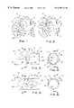
- FIGS. 1 and 2are cut away views of a heart and the aorta into which a catheter pump is inserted;
- FIG. 3is a side view in cross-section along the line III—III in FIG. 4 of a fitting according to the invention
- FIG. 4is a side view in cross-section along the line IV—IV in FIG. 3;
- FIG. 5is a side view in cross-section along the line V—V in FIG. 6 of the fitting according to FIGS. 3 and 4 in a different operating condition;
- FIG. 6is a side view in cross-section along the line VI—VI in FIG. 5;
- FIG. 7is a side view in longitudinal cross-section of a section of a catheter according to another embodiment of the invention.
- FIG. 8is a view according to FIG. 7 but in a different operating condition.
- FIGS. 1 and 2a heart 1 and a aorta 2 connected thereto are depicted.
- the hearthas a left ventricle 3 and an aortic valve 4 .
- a pulsatile cardiac assist catheter pump 5has a displacement device 6 in the form of a rigid housing 7 enclosing a chamber 8 divided by a flexible membrane 9 .
- the catheter pump 5further has a catheter 10 projecting from that displacement device 6 and communicating with a portion of the chamber 8 on a distal side of the membrane 9 and a pneumatic conduit 11 communicating with a pump drive unit (not shown) and with a portion of the chamber 8 on a proximal side of the membrane 9 .
- the displacement structure 6can be driven via the pneumatic conduit 11 for alternatingly applying suction for displacing fluid from the catheter 10 to the displacement structure 6 and for applying pressure for displacing fluid from the displacement structure 6 to the catheter 10 , thus driving a flow through the catheter 10 which reverses in a pulsating manner.
- the pump drive unitis preferably controlled to operate in accordance with pulsating contractions and relaxations of the left ventricle 3 .
- the pump drive unitis connected to a control unit adapted for detecting electrocardiac signals and for controlling the pump in accordance with detected electrocardiac signals.
- the catheter 10projects from the displacement device 6 via an axillary or femoral artery and the aorta 2 into the left ventricle 3 .
- a distal end portion 12 of the catheter 10is provided with inlet passages 13 . Spaced in proximal direction from the inlet passages 13 , the catheter 10 is provided with a fitting 14 having an outlet passage 15 at a distance of 12 cm from the distal tip of the catheter 10 . To ensure that in installed condition the outlet is located in a suitable position in the aorta the distance between the distal tip of the catheter and the outlet passage is preferably 8 to 16 cm and more preferably about 10 to 14 cm.
- the fitting 14is shown in more detail in FIGS. 3-6.
- the catheter pump, the catheter and the fitting as shown in FIGS. 1-6represent the presently most preferred embodiments of the invention.
- the fitting 14has a tube shaped housing wall 17 .
- the housinghas a circular cross-section, but other cross-sectional shapes are conceivable as well, such as oval, lens-shaped, rectangular, triangular etc. However, smooth outer shapes are preferred in order to interfere as little as possible with the operation of the aortic valve 4 .
- the fitting 14further has a coupling 18 for coupling to a distal portion of the catheter 10 on one end and a coupling 19 for coupling to a proximal portion of the catheter 10 on its opposite end.
- the representation in the drawings of the couplings 18 , 19 for coupling to the catheter 10is of a schematic nature.
- the couplingsare preferably made as is described in applicant's International patent application WO 97/18936.
- the fitting 14has three passages.
- a first passage 20 through the coupling 18 for coupling to the distal portion of the catheter 10a second passage 21 through the coupling 19 for coupling to a proximal portion of a catheter 10 and a third passage communicating with the first and second passages 20 , 21 which is formed by the opening 15 .
- the fitting 14is further provided with a valve structure for blocking outward blood flow via the inlet passages 13 and inward blood flow via the outlet passage 15 .
- the valve arrangementis formed by a valve body 16 movable between an inlet position substantially obstructing flow through the outlet passage 15 —i.e. the third passage of the fitting 14 —and allowing flow through the inlet passage 13 and the first passage 20 of the fitting 14 (FIGS. 5 and 6) and an outlet position substantially obstructing flow through the inlet passage 13 and the first passage 20 of the fitting 14 and allowing flow through the outlet passage 15 (FIGS. 3 and 4 ).
- valve body 16Although it would in principle be possible to control the motions of the valve body 16 actively in accordance with operation of the pump drive unit, it is preferred to control the motions of the valve body 16 passively, such that the valve body 16 is movable from the inlet position (FIGS. 5 and 6 ) to the outlet position (FIGS. 3 and 4) in response to suction applied by the displacement structure 6 to and via the second passage 21 and movable from the outlet position to the inlet position in response to pressure applied by the displacement structure 6 to and via the second passage 21 .
- the need of providing a drive unit and provisions for feeding power to the drive unitare avoided, and the costs and complexity of the construction are reduced while the reliability is improved.
- the valve body 16In operation, when the displacement device 6 takes in blood from the catheter 10 , the valve body 16 is urged into the position shown in FIGS. 5 and 6 which causes blood to be withdrawn from the left ventricle 3 and through the catheter 10 as is indicated by arrows 22 - 26 shown in FIGS. 1, 5 and 6 , After the desired volume of blood for the support of one stroke has been collected and when it has become time for completing the stroke, the pump drive unit is controlled to reverse from withdrawing air form the chamber 8 to pressing air into the chamber 8 . In response, blood is pressed into the catheter 10 and the blood flow in the catheter 10 is reversed as is indicated by the arrows 27 , 28 in FIG. 2 .
- valve member 16In response to the reversal of the blood flow, the valve member 16 is urged from the inlet position shown in FIGS. 5 and 6 into the outlet position shown in FIGS. 3 and 4. This causes the blood flow to be prevented from flowing back through the first passage 20 and the inlet openings 13 (possibly apart from some leakage) and to be forced out of the catheter 10 via the outlet opening 15 in an upstream portion of the aorta 2 , as is indicated by arrows 29 in FIGS. 3 and 4.
- valve body 16Since the valve body 16 is located inside the catheter 10 , the valve body 16 does not add to the cross-section of the catheter 10 , which is advantageous for facilitating insertion of the catheter 10 and to keep damage to tissue of the patient as small as possible. Furthermore, the risk of damaging the valve is reduced as well.
- interspaces 31 , 32 , 33 between the valve body 16 and the wall 17 of the fitting 14are each open on at least two opposite sides for allowing blood to flow through the interspaces. This counteracts the formation of stagnation zones where blood is prone to clot. Thus the risk of the formation of thromboses at the valve is further reduced. Thrombogenetic blood flow stagnation zones are further counteracted since the valve body 6 allows some leakage, so that in each operating condition the interspaces are flushed due to the pressure drop over the valve body 16 .
- the housing wall 17 of the fitting 14 of the catheter 10bounds a lumen 34 and the outlet opening 15 is formed by an opening in the wall 17 .
- the valve body 16is formed by a plate-shaped member which extends closely along and inside a projection of the wall 17 in the area of the opening 15 when in the inlet position shown in FIGS. 5 and 6.
- the valve body 16When in the outlet position shown in FIGS. 3 and 4, the valve body 16 extends transversely across a section of the lumen 34 on a distal side of the outlet opening 15 .
- the valve body 16is pivotable between the inlet position and the outlet position about an axis 35 extending across a central portion of the lumen 34 and centrally located behind the opening 15 .
- a distal edge portion-of the valve body 16is in abutment with a portion of the wall 17 of the fitting 14 bounding a distal side of the opening 15 .
- a particular advantage of this embodimentis, that the pressure in the aorta 2 does not tend to press the valve body 16 away from its position occluding the opening 15 , because resulting torques caused by pressure in the aorta 2 higher than pressure in the lumen 34 essentially cancel each other out.
- valve body 16When the flow is reversed, the forces exerted onto valve body 16 by the drag of the blood flow are inverted, which causes the valve body 16 to be entrained to the outlet position shown in FIGS. 3 and 4.
- valve body 16is entrained back to the inlet position shown in FIGS. 5 and 6.
- the lumen 34has a circular cross-section.
- a circular cross-sectionprovides the advantage of smoothness, which helps to prevent damage to vessels and other tissue of the patient.
- the opening 15is round in a view frontal thereto and wedge-shaped in a side view perpendicular to that frontal view, and the plate-shaped member is curved about axes of curvature transverse to the pivoting axis 35 , and round in frontal view and wedge-shaped in a side view perpendicular thereto.
- Thisallows a vary large opening in the wall 17 of the fitting 14 to be alternatingly occluded and cleared by a valve body 16 which also clears, respectively occludes the round lumen 34 when in the outlet position extending transversely across the lumen 34 .
- the opening 15 provided according to the present exampleis particularly large, because, in side view, opposite sides of the wedge shapes of the opening and of the valve body extend approximately perpendicular to each other, for instance at an angle of 75-105° and preferably about 90° to each other.
- the valve body 16In the inlet position, the valve body 16 has a frontal projected area having a portion 36 on a proximal side of the pivoting axis 35 and a portion 37 on a distal side of the axis 35 .
- the portion 36 on the proximal side of the pivoting axis 35is larger than the portion 37 on the distal side of the pivoting axis 35 .
- the valve body. 16has a frontal projected area having a portion 38 on a side of the pivoting axis 35 where the opening 15 is located and a portion 39 on an opposite side of the pivoting axis 35 .
- the portion 38 on the side of the pivoting axis 35 where the opening 15 is locatedis larger than the portion 39 on the opposite side of the pivoting axis 35 .
- This difference between the sizes of the frontal area portions 38 , 39 on opposite sides of the pivoting axis 35causes the valve body to be firmly urged into and retained in the outlet position by a pressure drop over the valve body 16 from the proximal side to the distal side as occurs during the outflow of blood under influence of pressure exerted by the displacement device 6 . Conversely, if the pressure drop over the valve body 16 is inverted due to the reversal of the operation of the displacement device 6 , this feature supports a quick movement of the valve body out of the outlet position.
- the portion of the cross section of the lumen 34 on the side of the pivoting axis 35 where the opening 15 is locatedis larger than the portion of the cross section of the lumen 34 on the opposite side of that pivoting axis 35 .
- the desired difference in size between the projected frontal area portions 36 and 37 as well as 38 and 39is obtained by providing that the location of the pivoting axis 35 is on the one hand offset from the central axis 40 of the lumen 34 in a direction away from the opening 15 and on the other hand offset from the center of the opening 15 in a distal direction.
- These offsetsare indicated by reference mark A in FIG. 3 and, respectively, reference mark B in FIG. 4 .
- an opening 115is provided in a wall 117 of the catheter 110 in essentially the same position as the opening 15 shown in FIGS. 1 and 2.
- the valve body 116is formed by a plate-shaped member. When in the inlet position, the valve body 116 extends closely along and inside a projection of the wall 117 in the area of the opening 115 (FIG. 8 ). Furthermore, the valve body 116 has a deflector 141 projecting into the lumen 134 on a proximal side of the valve body 116 . When in the outlet position, the valve body 116 extends diagonally across a section of said lumen 134 in the area of the outlet opening 115 (FIG. 7 ). The valve body 116 is pivotable between the inlet position and the outlet position and is hinged to the wall 117 about an axis 135 closely adjacent a distal end portion of the opening 115 .
- the valve body 116When the displacement device 6 is operative for drawing blood in proximal direction—as indicated by arrows 123 , 124 in FIG. 8 —the valve body 116 is urged and retained in its inlet position by the forces exerted by the flow onto the inside of the valve body 116 .
- the deflector 141In order to counteract a pressure drop from the aorta 2 to the interior of the catheter 110 , the deflector 141 causes an additional closing force exerted onto the valve body 116 . Due to the large distance between the deflector 141 and the pivoting axis 135 where the valve body 116 is hinged to the wall 117 , the deflector 141 causes the generation of a substantial closing torque about the axis 135 .
- the blood flow(indicated by arrow 129 ) hitting the deflector 141 causes the valve body 116 to be opened.
- the pressure drop over the valve body 116 from the proximal side to the distal side which is subsequently causedcauses the valve body 116 to be retained in the outlet position as long as the flow 129 is maintained.
- valve bodyin the catheter without the use of a fitting.
- Other exemplary alternativesare to provide the valve body in the form of a flap connected to the catheter wall or the wall of a fitting by a flexible connection or to provide that the valve body is guided for translatory movement between the inlet position and the outlet position.
Landscapes
- Health & Medical Sciences (AREA)
- Heart & Thoracic Surgery (AREA)
- Engineering & Computer Science (AREA)
- Life Sciences & Earth Sciences (AREA)
- Cardiology (AREA)
- General Health & Medical Sciences (AREA)
- Veterinary Medicine (AREA)
- Anesthesiology (AREA)
- Biomedical Technology (AREA)
- Hematology (AREA)
- Animal Behavior & Ethology (AREA)
- Public Health (AREA)
- Mechanical Engineering (AREA)
- Vascular Medicine (AREA)
- Physics & Mathematics (AREA)
- Optics & Photonics (AREA)
- Biophysics (AREA)
- Pulmonology (AREA)
- Urology & Nephrology (AREA)
- External Artificial Organs (AREA)
- Materials For Medical Uses (AREA)
- Infusion, Injection, And Reservoir Apparatuses (AREA)
Abstract
Description
Claims (24)
Priority Applications (5)
| Application Number | Priority Date | Filing Date | Title |
|---|---|---|---|
| US09/363,711US6398714B1 (en) | 1999-07-29 | 1999-07-29 | Cardiac assist catheter pump and catheter and fitting for use therein |
| AT00202703TATE319490T1 (en) | 1999-07-29 | 2000-07-27 | CATHETER FOR CARDIAC SUPPORT, CATHETER PUMP FOR CARDIAC SUPPORT AND FITTING FOR SUCH A CATHETER |
| EP00202703AEP1072278B1 (en) | 1999-07-29 | 2000-07-27 | Cardiac assits catheter, cardiac assit catheter pump and fitting for a cardiac assist catheter |
| DE60026444TDE60026444T2 (en) | 1999-07-29 | 2000-07-27 | Cardiac assist catheter, cardiac assist catheter pump, and fitting for such a catheter |
| US10/072,348US6974409B2 (en) | 1999-07-29 | 2002-02-07 | Catheter pump, catheter and method for supporting organ perfusion |
Applications Claiming Priority (1)
| Application Number | Priority Date | Filing Date | Title |
|---|---|---|---|
| US09/363,711US6398714B1 (en) | 1999-07-29 | 1999-07-29 | Cardiac assist catheter pump and catheter and fitting for use therein |
Related Child Applications (1)
| Application Number | Title | Priority Date | Filing Date |
|---|---|---|---|
| US10/072,348Continuation-In-PartUS6974409B2 (en) | 1999-07-29 | 2002-02-07 | Catheter pump, catheter and method for supporting organ perfusion |
Publications (1)
| Publication Number | Publication Date |
|---|---|
| US6398714B1true US6398714B1 (en) | 2002-06-04 |
Family
ID=23431382
Family Applications (2)
| Application Number | Title | Priority Date | Filing Date |
|---|---|---|---|
| US09/363,711Expired - LifetimeUS6398714B1 (en) | 1999-07-29 | 1999-07-29 | Cardiac assist catheter pump and catheter and fitting for use therein |
| US10/072,348Expired - LifetimeUS6974409B2 (en) | 1999-07-29 | 2002-02-07 | Catheter pump, catheter and method for supporting organ perfusion |
Family Applications After (1)
| Application Number | Title | Priority Date | Filing Date |
|---|---|---|---|
| US10/072,348Expired - LifetimeUS6974409B2 (en) | 1999-07-29 | 2002-02-07 | Catheter pump, catheter and method for supporting organ perfusion |
Country Status (4)
| Country | Link |
|---|---|
| US (2) | US6398714B1 (en) |
| EP (1) | EP1072278B1 (en) |
| AT (1) | ATE319490T1 (en) |
| DE (1) | DE60026444T2 (en) |
Cited By (11)
| Publication number | Priority date | Publication date | Assignee | Title |
|---|---|---|---|---|
| WO2005021078A1 (en) | 2003-09-02 | 2005-03-10 | Intra-Vasc.Nl B.V. | Catheter pump, catheter and fittings therefore and methods of using a catheter pump. |
| US20050085684A1 (en)* | 2003-09-02 | 2005-04-21 | Gerhard Rakhorst | Catheter pump, catheter and fittings therefore and methods of using a catheter pump |
| ES2233135A1 (en)* | 2002-09-11 | 2005-06-01 | Salvador Merce Vives | Cardiac support device for patient, has console control unit provided with driving element for activating pump, where console control unit is provided with outlet nozzle and driving element is equipped with synchronization unit |
| US20050148810A1 (en)* | 2004-01-06 | 2005-07-07 | Riebman Jerome B. | Devices and methods for blood flow assistance |
| WO2012158437A3 (en)* | 2011-05-13 | 2013-03-14 | Mayo Foundation For Medical Education And Research | Cannula apparatus and ventricular assist systems using the cannula apparatus |
| US9636442B2 (en) | 2012-01-17 | 2017-05-02 | Pulsecath B.V. | Pressure actuated single-lumen blood pumping device |
| US10322230B2 (en) | 2016-06-09 | 2019-06-18 | C. R. Bard, Inc. | Systems and methods for correcting and preventing occlusion in a catheter |
| CN116159241A (en)* | 2021-11-25 | 2023-05-26 | 北京新尖科技有限公司 | Ventricular Assist Pumping Device |
| CN117339098A (en)* | 2023-05-30 | 2024-01-05 | 中国医学科学院阜外医院深圳医院(深圳市孙逸仙心血管医院) | Circulation assistance device for providing pulsatile blood flow |
| WO2024072208A1 (en)* | 2022-09-30 | 2024-04-04 | Pulsecath B.V. | Catheter valve, catheter and assembly method |
| CN118681125A (en)* | 2024-06-07 | 2024-09-24 | 苏州心岭迈德医疗科技有限公司 | A pulsating pump bidirectional valve and ventricular assist device |
Families Citing this family (34)
| Publication number | Priority date | Publication date | Assignee | Title |
|---|---|---|---|---|
| US8721515B2 (en)* | 2003-01-31 | 2014-05-13 | L-Vad Technology, Inc. | Rigid body aortic blood pump implant |
| WO2009108654A2 (en)* | 2008-02-25 | 2009-09-03 | Clemson University | Differential pressure pump system |
| US20090270815A1 (en)* | 2008-04-29 | 2009-10-29 | Infraredx, Inc. | Catheter Priming System |
| EP2194278A1 (en) | 2008-12-05 | 2010-06-09 | ECP Entwicklungsgesellschaft mbH | Fluid pump with a rotor |
| EP2216059A1 (en) | 2009-02-04 | 2010-08-11 | ECP Entwicklungsgesellschaft mbH | Catheter device with a catheter and an actuation device |
| EP2229965A1 (en) | 2009-03-18 | 2010-09-22 | ECP Entwicklungsgesellschaft mbH | Fluid pump with particular form of a rotor blade |
| EP2246078A1 (en) | 2009-04-29 | 2010-11-03 | ECP Entwicklungsgesellschaft mbH | Shaft assembly with a shaft which moves within a fluid-filled casing |
| EP2248544A1 (en) | 2009-05-05 | 2010-11-10 | ECP Entwicklungsgesellschaft mbH | Fluid pump with variable circumference, particularly for medical use |
| EP2266640A1 (en) | 2009-06-25 | 2010-12-29 | ECP Entwicklungsgesellschaft mbH | Compressible and expandable turbine blade for a fluid pump |
| EP2282070B1 (en) | 2009-08-06 | 2012-10-17 | ECP Entwicklungsgesellschaft mbH | Catheter device with a coupling device for a drive device |
| EP2298373A1 (en) | 2009-09-22 | 2011-03-23 | ECP Entwicklungsgesellschaft mbH | Fluid pump with at least one turbine blade and a seating device |
| EP2299119B1 (en) | 2009-09-22 | 2018-11-07 | ECP Entwicklungsgesellschaft mbH | Inflatable rotor for a fluid pump |
| EP2298371A1 (en) | 2009-09-22 | 2011-03-23 | ECP Entwicklungsgesellschaft mbH | Function element, in particular fluid pump with a housing and a transport element |
| EP2298372A1 (en) | 2009-09-22 | 2011-03-23 | ECP Entwicklungsgesellschaft mbH | Rotor for an axial pump for transporting a fluid |
| EP2314331B1 (en) | 2009-10-23 | 2013-12-11 | ECP Entwicklungsgesellschaft mbH | Catheter pump arrangement and flexible shaft arrangement with a cable core |
| EP2314330A1 (en) | 2009-10-23 | 2011-04-27 | ECP Entwicklungsgesellschaft mbH | Flexible shaft arrangement |
| EP2338541A1 (en) | 2009-12-23 | 2011-06-29 | ECP Entwicklungsgesellschaft mbH | Radial compressible and expandable rotor for a fluid pump |
| EP2338539A1 (en) | 2009-12-23 | 2011-06-29 | ECP Entwicklungsgesellschaft mbH | Pump device with a detection device |
| EP2338540A1 (en) | 2009-12-23 | 2011-06-29 | ECP Entwicklungsgesellschaft mbH | Delivery blade for a compressible rotor |
| EP2347778A1 (en) | 2010-01-25 | 2011-07-27 | ECP Entwicklungsgesellschaft mbH | Fluid pump with a radially compressible rotor |
| EP2363157A1 (en) | 2010-03-05 | 2011-09-07 | ECP Entwicklungsgesellschaft mbH | Device for exerting mechanical force on a medium, in particular fluid pump |
| EP2388029A1 (en) | 2010-05-17 | 2011-11-23 | ECP Entwicklungsgesellschaft mbH | Pump array |
| EP2399639A1 (en) | 2010-06-25 | 2011-12-28 | ECP Entwicklungsgesellschaft mbH | System for introducing a pump |
| EP2407186A1 (en) | 2010-07-15 | 2012-01-18 | ECP Entwicklungsgesellschaft mbH | Rotor for a pump, produced with an initial elastic material |
| EP2407185A1 (en) | 2010-07-15 | 2012-01-18 | ECP Entwicklungsgesellschaft mbH | Radial compressible and expandable rotor for a pump with a turbine blade |
| EP2407187A3 (en) | 2010-07-15 | 2012-06-20 | ECP Entwicklungsgesellschaft mbH | Blood pump for invasive application within the body of a patient |
| EP2422735A1 (en) | 2010-08-27 | 2012-02-29 | ECP Entwicklungsgesellschaft mbH | Implantable blood transportation device, manipulation device and coupling device |
| EP2497521A1 (en) | 2011-03-10 | 2012-09-12 | ECP Entwicklungsgesellschaft mbH | Push device for axial insertion of a string-shaped, flexible body |
| EP2564771A1 (en) | 2011-09-05 | 2013-03-06 | ECP Entwicklungsgesellschaft mbH | Medicinal product with a functional element for invasive use in the body of a patient |
| US8926492B2 (en) | 2011-10-11 | 2015-01-06 | Ecp Entwicklungsgesellschaft Mbh | Housing for a functional element |
| US20170000935A1 (en) | 2014-01-27 | 2017-01-05 | Children's Medical Center Corporation | Mechanical assist device |
| CN113018543B (en)* | 2021-03-02 | 2021-10-08 | 江苏赛腾医疗科技有限公司 | A diversion control system |
| AT525884B1 (en)* | 2022-03-14 | 2023-09-15 | Mohl Werner | Blood pump to support the performance of a heart |
| WO2025147860A1 (en)* | 2024-01-09 | 2025-07-17 | 脉柯斯医疗科技(上海)有限公司 | Pulsatile percutaneous ventricular assist device and two-way valve thereof |
Citations (8)
| Publication number | Priority date | Publication date | Assignee | Title |
|---|---|---|---|---|
| FR2144806A1 (en) | 1971-07-06 | 1973-02-16 | Inst Med | |
| US3995617A (en) | 1972-05-31 | 1976-12-07 | Watkins David H | Heart assist method and catheter |
| US4014317A (en) | 1972-02-18 | 1977-03-29 | The United States Of America As Represented By The Department Of Health, Education And Welfare | Multipurpose cardiocirculatory assist cannula and methods of use thereof |
| WO1989010763A1 (en) | 1988-05-03 | 1989-11-16 | Nimbus Medical, Inc. | High-frequency transvalvular axisymmetric blood pump |
| WO1997002850A1 (en) | 1995-07-10 | 1997-01-30 | Medicard Ltd. | Heart assist system |
| WO1998057698A1 (en) | 1997-06-18 | 1998-12-23 | H.D.S. Systems, Ltd. | Cannula pump valves |
| WO1999026676A1 (en) | 1997-11-24 | 1999-06-03 | H.D.S. Systems, Ltd | Heart assist system with apex cannula pump |
| US6007479A (en)* | 1996-07-08 | 1999-12-28 | H.D.S. Systems Ltd. | Heart assist system and method |
Family Cites Families (2)
| Publication number | Priority date | Publication date | Assignee | Title |
|---|---|---|---|---|
| US3592184A (en)* | 1969-12-16 | 1971-07-13 | David H Watkins | Heart assist method and catheter |
| WO1997018936A1 (en) | 1995-11-22 | 1997-05-29 | Rijksuniversiteit Te Groningen | A method and a system for manufacturing a catheter and a catheter manufactured by that method |
- 1999
- 1999-07-29USUS09/363,711patent/US6398714B1/ennot_activeExpired - Lifetime
- 2000
- 2000-07-27ATAT00202703Tpatent/ATE319490T1/enactive
- 2000-07-27EPEP00202703Apatent/EP1072278B1/ennot_activeExpired - Lifetime
- 2000-07-27DEDE60026444Tpatent/DE60026444T2/ennot_activeExpired - Lifetime
- 2002
- 2002-02-07USUS10/072,348patent/US6974409B2/ennot_activeExpired - Lifetime
Patent Citations (10)
| Publication number | Priority date | Publication date | Assignee | Title |
|---|---|---|---|---|
| FR2144806A1 (en) | 1971-07-06 | 1973-02-16 | Inst Med | |
| GB1370546A (en) | 1971-07-06 | 1974-10-16 | V Ni I Ispytatelny I Med Tekhn | Device for facilitating cardiac action |
| US4014317A (en) | 1972-02-18 | 1977-03-29 | The United States Of America As Represented By The Department Of Health, Education And Welfare | Multipurpose cardiocirculatory assist cannula and methods of use thereof |
| GB1528072A (en) | 1972-02-18 | 1978-10-11 | Bruno A | Multipurpose cardiocirculatory assist device |
| US3995617A (en) | 1972-05-31 | 1976-12-07 | Watkins David H | Heart assist method and catheter |
| WO1989010763A1 (en) | 1988-05-03 | 1989-11-16 | Nimbus Medical, Inc. | High-frequency transvalvular axisymmetric blood pump |
| WO1997002850A1 (en) | 1995-07-10 | 1997-01-30 | Medicard Ltd. | Heart assist system |
| US6007479A (en)* | 1996-07-08 | 1999-12-28 | H.D.S. Systems Ltd. | Heart assist system and method |
| WO1998057698A1 (en) | 1997-06-18 | 1998-12-23 | H.D.S. Systems, Ltd. | Cannula pump valves |
| WO1999026676A1 (en) | 1997-11-24 | 1999-06-03 | H.D.S. Systems, Ltd | Heart assist system with apex cannula pump |
Cited By (18)
| Publication number | Priority date | Publication date | Assignee | Title |
|---|---|---|---|---|
| ES2233135A1 (en)* | 2002-09-11 | 2005-06-01 | Salvador Merce Vives | Cardiac support device for patient, has console control unit provided with driving element for activating pump, where console control unit is provided with outlet nozzle and driving element is equipped with synchronization unit |
| ES2233135B1 (en)* | 2002-09-11 | 2006-08-01 | Salvador Merce Vives | APPARATUS FOR CARDIAC SUPPORT OF PULSATILE FLOW. |
| WO2005021078A1 (en) | 2003-09-02 | 2005-03-10 | Intra-Vasc.Nl B.V. | Catheter pump, catheter and fittings therefore and methods of using a catheter pump. |
| US20050085684A1 (en)* | 2003-09-02 | 2005-04-21 | Gerhard Rakhorst | Catheter pump, catheter and fittings therefore and methods of using a catheter pump |
| US7494477B2 (en) | 2003-09-02 | 2009-02-24 | Pulsecath B.V. | Catheter pump, catheter and fittings therefore and methods of using a catheter pump |
| US7988655B2 (en) | 2003-09-02 | 2011-08-02 | Pulsecath B.V. | Catheter pump, catheter and fittings therefore and methods of using a catheter pump |
| US20050148810A1 (en)* | 2004-01-06 | 2005-07-07 | Riebman Jerome B. | Devices and methods for blood flow assistance |
| US7066874B2 (en) | 2004-01-06 | 2006-06-27 | Bay Innovation Group, Llc | Devices and methods for blood flow assistance |
| WO2012158437A3 (en)* | 2011-05-13 | 2013-03-14 | Mayo Foundation For Medical Education And Research | Cannula apparatus and ventricular assist systems using the cannula apparatus |
| US10226558B2 (en) | 2011-05-13 | 2019-03-12 | Mayo Foundation For Medical Education And Research | Cannula apparatus and ventricular assist systems using the cannula apparatus |
| US9636442B2 (en) | 2012-01-17 | 2017-05-02 | Pulsecath B.V. | Pressure actuated single-lumen blood pumping device |
| US10322230B2 (en) | 2016-06-09 | 2019-06-18 | C. R. Bard, Inc. | Systems and methods for correcting and preventing occlusion in a catheter |
| US12005228B2 (en) | 2016-06-09 | 2024-06-11 | C. R. Bard, Inc. | Systems and methods for correcting and preventing occlusion in a catheter |
| CN116159241A (en)* | 2021-11-25 | 2023-05-26 | 北京新尖科技有限公司 | Ventricular Assist Pumping Device |
| CN116159241B (en)* | 2021-11-25 | 2025-09-02 | 北京新尖科技有限公司 | ventricular assist pumping device |
| WO2024072208A1 (en)* | 2022-09-30 | 2024-04-04 | Pulsecath B.V. | Catheter valve, catheter and assembly method |
| CN117339098A (en)* | 2023-05-30 | 2024-01-05 | 中国医学科学院阜外医院深圳医院(深圳市孙逸仙心血管医院) | Circulation assistance device for providing pulsatile blood flow |
| CN118681125A (en)* | 2024-06-07 | 2024-09-24 | 苏州心岭迈德医疗科技有限公司 | A pulsating pump bidirectional valve and ventricular assist device |
Also Published As
| Publication number | Publication date |
|---|---|
| EP1072278B1 (en) | 2006-03-08 |
| DE60026444D1 (en) | 2006-05-04 |
| EP1072278A2 (en) | 2001-01-31 |
| US20020123661A1 (en) | 2002-09-05 |
| US6974409B2 (en) | 2005-12-13 |
| DE60026444T2 (en) | 2006-10-19 |
| EP1072278A3 (en) | 2001-09-12 |
| ATE319490T1 (en) | 2006-03-15 |
Similar Documents
| Publication | Publication Date | Title |
|---|---|---|
| US6398714B1 (en) | Cardiac assist catheter pump and catheter and fitting for use therein | |
| EP1673127B1 (en) | Catheter pump | |
| CA2206015C (en) | Suction catheter with preformed tip | |
| US7988655B2 (en) | Catheter pump, catheter and fittings therefore and methods of using a catheter pump | |
| EP3403683B1 (en) | Percutaneous catheter | |
| JP4806350B2 (en) | Intracardiac pumping device | |
| JP4163384B2 (en) | Intracardiac blood pump | |
| CA2160408C (en) | Suction catheter | |
| CA2103035C (en) | Bidirectional valved catheter | |
| US6059745A (en) | Thrombectomy device and associated method | |
| JP4549678B2 (en) | Multi-lumen catheter to minimize limb ischemia | |
| WO2002030489A3 (en) | Peritoneal dialysis catheters | |
| JPH06197951A (en) | Washing catheter | |
| JPH11514251A (en) | Heart assist system | |
| DE68921627D1 (en) | Transvalvuläre, achssymmetrische hochfrequenzblutpumpe. | |
| JP2004506490A (en) | Intracardiac blood pump | |
| AU7488000A (en) | Perfusion cannula, method and system | |
| JP4050355B2 (en) | Medical substance removal instrument | |
| CN116712666A (en) | A blood flow guiding valve and its ventricular assist pump device | |
| CN113018543B (en) | A diversion control system | |
| WO2018133175A1 (en) | Slidable multi-lumen drainage tube | |
| KR102525303B1 (en) | A blood pump and an oxidation system having the same that flows blood in one direction | |
| CN120022527A (en) | Two-way valve and pulsatile interventional ventricular assist device | |
| CN120695342A (en) | Pulsatile interventional ventricular assist device and its bidirectional valve | |
| MXPA00000382A (en) | Intracardiac blood pump |
Legal Events
| Date | Code | Title | Description |
|---|---|---|---|
| AS | Assignment | Owner name:RIJKSUNIVERSITEIT TE GRONINGEN, NETHERLANDS Free format text:ASSIGNMENT OF ASSIGNORS INTEREST;ASSIGNORS:VERKERKE, GIJSBERTUS JACOB;VAN DER PLAATS, ARJAN;RAKHORST, GERHARD;REEL/FRAME:010357/0131 Effective date:19991020 | |
| AS | Assignment | Owner name:INTRA-VASC.NL B.V., NETHERLANDS Free format text:ASSIGNMENT OF ASSIGNORS INTEREST;ASSIGNOR:RIJKSUNIVERSITEIT TE GRONINGEN;REEL/FRAME:012092/0755 Effective date:20010111 | |
| STCF | Information on status: patent grant | Free format text:PATENTED CASE | |
| CC | Certificate of correction | ||
| CC | Certificate of correction | ||
| FPAY | Fee payment | Year of fee payment:4 | |
| FEPP | Fee payment procedure | Free format text:PAYOR NUMBER ASSIGNED (ORIGINAL EVENT CODE: ASPN); ENTITY STATUS OF PATENT OWNER: SMALL ENTITY | |
| AS | Assignment | Owner name:TZAMAL MEDICAL SUPPLIES INDUSTRIES LTD., ISRAEL Free format text:ASSIGNMENT OF ASSIGNORS INTEREST;ASSIGNOR:INTRA-VASC.NL B.V.;REEL/FRAME:021952/0688 Effective date:20080530 | |
| AS | Assignment | Owner name:PULSECATH B.V., NETHERLANDS Free format text:ASSIGNMENT OF ASSIGNORS INTEREST;ASSIGNOR:TZAMAL MEDICAL SUPPLIES INDUSTRIES LTD.;REEL/FRAME:021965/0535 Effective date:20081110 | |
| REMI | Maintenance fee reminder mailed | ||
| FPAY | Fee payment | Year of fee payment:8 | |
| SULP | Surcharge for late payment | Year of fee payment:7 | |
| FPAY | Fee payment | Year of fee payment:12 |