US6398368B2 - Light pipe for a projector system - Google Patents
Light pipe for a projector systemDownload PDFInfo
- Publication number
- US6398368B2 US6398368B2US09/858,514US85851401AUS6398368B2US 6398368 B2US6398368 B2US 6398368B2US 85851401 AUS85851401 AUS 85851401AUS 6398368 B2US6398368 B2US 6398368B2
- Authority
- US
- United States
- Prior art keywords
- light
- light pipe
- pipe
- entrance pupil
- exit pupil
- Prior art date
- Legal status (The legal status is an assumption and is not a legal conclusion. Google has not performed a legal analysis and makes no representation as to the accuracy of the status listed.)
- Expired - Lifetime
Links
Images


Classifications
- G—PHYSICS
- G03—PHOTOGRAPHY; CINEMATOGRAPHY; ANALOGOUS TECHNIQUES USING WAVES OTHER THAN OPTICAL WAVES; ELECTROGRAPHY; HOLOGRAPHY
- G03B—APPARATUS OR ARRANGEMENTS FOR TAKING PHOTOGRAPHS OR FOR PROJECTING OR VIEWING THEM; APPARATUS OR ARRANGEMENTS EMPLOYING ANALOGOUS TECHNIQUES USING WAVES OTHER THAN OPTICAL WAVES; ACCESSORIES THEREFOR
- G03B21/00—Projectors or projection-type viewers; Accessories therefor
- G03B21/14—Details
- G03B21/20—Lamp housings
- G03B21/2006—Lamp housings characterised by the light source
- G03B21/2026—Gas discharge type light sources, e.g. arcs
- Y—GENERAL TAGGING OF NEW TECHNOLOGICAL DEVELOPMENTS; GENERAL TAGGING OF CROSS-SECTIONAL TECHNOLOGIES SPANNING OVER SEVERAL SECTIONS OF THE IPC; TECHNICAL SUBJECTS COVERED BY FORMER USPC CROSS-REFERENCE ART COLLECTIONS [XRACs] AND DIGESTS
- Y10—TECHNICAL SUBJECTS COVERED BY FORMER USPC
- Y10S—TECHNICAL SUBJECTS COVERED BY FORMER USPC CROSS-REFERENCE ART COLLECTIONS [XRACs] AND DIGESTS
- Y10S385/00—Optical waveguides
- Y10S385/901—Illuminating or display apparatus
Definitions
- the present inventionrelates to a light pipe, and more particularly, to a hollow tapering light pipe.
- projected light intensityis usually an important factor while designing a projector, as the projection quality improves with greater intensities of the projected light.
- FIG. 1is a schematic diagram of a prior art light pipe 10 for a projector system 12 .
- the projector system 12comprises a light source 14 to generate light 11 and to guide the light 11 to the light pipe 10 , and an image device 16 to project the light gathered by the light pipe 10 to a screen 13 so as to form an image.
- the light pipe 10is a hollow rectangular pipe set between the light source 14 and the image device 16 to gather and guide the light 11 .
- the light pipe 10comprises an entrance pupil 18 and an exit pupil 19 .
- the entrance pupil 18is used to gather the light 11 generated by the light source 14 .
- the light 11is guided to the image device 16 through the exit pupil 19 .
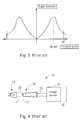
- FIG. 2is a position distribution of the light incident upon the entrance pupil 18 in FIG. 1 .
- the transverse axisis a distance in the plane 15 in FIG. 1 from the center of the entrance pupil 18 .
- the longitudinal axisis the light intensity. As shown in FIG. 2, the light closer to the center of the entrance pupil 18 is stronger, and the light farther from the center of the entrance pupil 18 is weaker.
- the light pipe 10does not gather all of the light 11 .
- the light 24 closer to the center of the entrance pupil 18enters the light pipe while the light 25 farther from the center of the entrance pupil 18 fails to be gathered by the light pipe 10 .
- FIG. 3is the incident angle distribution of the light incident upon the entrance pupil 18 .
- the transverse axis of FIG. 3is the incident angle of the light on the plane 15 , and the longitudinal axis is the light intensity.
- the incident angle of a traditional light bulbis in the range of 18-20 degrees.
- the light pipe 10is a rectangular pipe with homogeneous cross-sections, the angle of the light leaving of the exit pupil 19 is also in the range of 18-20 degrees.
- the optic device for the image device 16such as the liquid crystal display (LCD) or the digital mirror device (DMD), has an incident angle limitation. Owing to the incident angle limitation, the angle of the light leaving the exit pupil 19 cannot be too large. Usually, light with an angle over 30 degrees cannot be modulated by the liquid crystal display.
- FIG. 4is a schematic diagram of another prior art light pipe 20 for the projector system 12 in FIG. 1 .
- the light pipe 20differing from the light pipe 10 , has a tapered body.
- the exit pupil 23 of the light pipe 20is larger than the entrance pupil 22 to reduce the incident angle of the light.
- the light pipes 10 , 20are designed to reduce the light 25 leaking from the light pipes 10 , 20 while maintaining a small light angle.
- the light gathering efficiencyis improved, and the light intensity is increased.
- the prior art light pipes 10 , 20have the entrance pupil 18 , 22 smaller than or equal to the exit pupil 19 , 23 , the light 25 leaking from the light pipe 10 , 20 is usually quite strong without increasing the volumes of the light pipes 10 , 20 .
- an arc lamp with a longer arc lengthcan be used as the light source to reduce the incident angle in FIG. 3, it also makes the position distribution of the light in FIG. 2 smoother. Then the light leaking from the light pipe 10 , 20 increases, degrading the light gathering efficiency.
- the light pipeis designed for a projector system.
- the projector systemcomprises a light source to generate light and to guide the light to the light pipe, and an image device to produce an image using the light gathered by the light pipe.
- the light pipeis a tapered hollow tube set between the light source and the image device.
- the light pipecomprises an entrance pupil and an exit pupil.
- the entrance pupilis a square opening at one end of the light pipe.
- the light generated by the light sourceis guided to the light pipe through the entrance pupil.
- the exit pupilis set at another end of the light pipe, and the area of the exit pupil is smaller than the area of the entrance pupil.
- the light gathered by the light pipeis guided to the image device through the exit pupil.
- the shape of the exit pupilis scaled from the shape of the entrance pupil so as to increase the light gathering efficiency of the light pipe.
- FIG. 1is a schematic diagram of a prior art light pipe used in a projector system.
- FIG. 2is the position distribution of the light incident upon the entrance pupil in FIG. 1 .
- FIG. 3is the incident angle distribution of the light incident upon the entrance pupil in FIG. 1 .
- FIG. 4is the schematic diagram of another prior art light pipe used in the projector system in FIG. 1 .
- FIG. 5is the schematic diagram of the light pipe of the present invention used in a projector system.
- FIG. 6is a view of the light pipe in FIG. 5 .
- FIG. 7is the position distribution of the light incident upon the entrance pupil in FIG. 5 .
- FIG. 8is the incident angle distribution of the light incident upon the entrance pupil in FIG. 5 .
- FIG. 9is the angle distribution of the light leaving the light pipe in FIG. 5 .
- FIG. 10is the relation between the opening ratio and the intensity of the light leaving the light pipe in FIG. 5 .
- FIG. 11is the schematic diagram of the light gathering efficiency improvement of the light pipe in FIG. 5 in comparison with the light pipe in FIG. 1 .
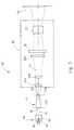
- FIG. 5is the schematic diagram of a light pipe 40 of the present invention used in a projector system 42 .
- the projector system 42comprises a light source 44 to generate light 46 and to guide the light 46 to the light pipe 40 , and an image device 48 to produce an image by projecting the light 46 gathered by the light pipe 40 to a screen 64 .
- the light pipe 40is set between the light source 44 and the image device 48 , and the projector system 42 is a projector or a liquid crystal display (LCD).
- LCDliquid crystal display
- the light source 44comprises an arc lamp 54 to generate light 46 , and a light collector 56 , which is a lampshade in the shape of a half ellipsoid, to collect the light 46 generated by the arc lamp 54 and guide the light 46 to the light pipe 40 .
- the arc lamp 54is a hyper pressure mercury arc light with a long arc length 55 (Ushio, 150W, NSH150), the arc length 55 being around 1.8 mm (0.0709 inches).
- the image device 48comprises a display panel 58 set on an image path 61 , a plurality of optic lenses 60 A, 60 B and 60 C set between the light pipe 40 and the display panel 58 , and a projection lens 62 .
- the lenses 60 A, 60 B and 60 Care used to guide the light 46 collected by the light pipe 40 to the display panel 58 to form the image.
- the projection lens 62is set between the display panel 58 and the screen 64 to project the image to the screen 64 .
- FIG. 6is a perspective view of the light pipe 40 in FIG. 5 .
- the light pipe 40is a hollow, tapering pipe constructed with four trapezoidal flat plates 62 .
- Each of the trapezoidal flat plates 62comprises a top end 62 A, a bottom end 62 B, and two sides 62 C.
- the sides 62 C of the trapezoidal flat plates 62are joined together to from the light pipe 40 .
- the light pipe 40further comprises four reflector walls (mirror coatings) 49 respectively set on the inner surfaces of the four trapezoidal flat plates 62 to reflect the light 46 to the image device 48 .
- the reflector walls 49absorb the infrared light in the light 46 and reflect the visible portion of the light 46 .
- the light pipe 40comprises an entrance pupil 50 and an exit pupil 52 .
- the entrance pupil 50 at one end of the light pipe 40is a rectangular opening formed by the four bottom ends 62 B of the four trapezoidal flat plates 62 .
- the exit pupil 52 at another end of the light pipe 40is a rectangular opening formed by the four top ends 62 A of the four trapezoidal flat plates 62 .
- the light 46 generated by the light source 44is guided to the light pipe 40 through the entrance pupil 50 , and the light 46 gathered by the light pipe 40 is guided to the image device 48 through the exit pupil 52 .
- the area of the exit pupil 52 of the light pipe 40is smaller than the area of the entrance pupil 50 , and the opening shape of the exit pupil 52 is scaled from the opening shape of the entrance pupil 50 .
- the ratio of the size of the entrance pupil 50 to the size of the exit pupil 52is defined as the opening ratio P.
- the length of the light pipe 40is 25 mm (0.98425 inch)
- the ratio of length to width for both the entrance pupil 50 and the exit pupil 52is 4/3 or 16/9
- the opening ratio P of the light pipe 40is about 1.25 to 1.35.
- FIG. 7is the position distribution of the light incident upon the entrance pupil 50 in FIG. 5 .
- FIG. 7is plotted with the transverse axis being a distance on a plane 51 A from the center of the entrance pupil 50 , and the longitudinal axis being the light intensity.
- the light pipe 40 of the present inventiongathers more light 66 and leaks less light 67 in spite of the smoother light position distribution of the arc lamp 54 in comparison with FIG. 2 .
- the entrance pupil 50 of the light pipe 40 of the present inventionis larger than the exit pupil 52 , and the shape of the entrance pupil 52 is scaled from that of the exit pupil 50 , the light gathering efficiency of the present invention is increased.
- FIG. 8is an incident angle distribution of the light incident upon the entrance pupil 50 in FIG. 5 .
- FIG. 8is plotted with the transverse axis being the incident angle of light on the plane 51 A, and the longitudinal axis being the light intensity.
- the incident angle of the lightconcentrates in the 10-14 degree range because the hyper pressure mercury light with a long arc length (Ushio, 150W, NSH150) is used in the preferred embodiment.
- FIG. 9is the angular distribution of the light leaving the light pipe 40 in FIG. 5 .
- the transverse axisis the angle of the light on a plane 51 B, and the longitudinal axis is the light intensity.
- the angular distributionis concentrated at ⁇ . Though ⁇ is larger than 14 degrees, it is far less than 30 degrees. Thus, the limitation of the incident angle for the display panel 58 is satisfied.
- FIG. 10is the relation between the intensity of the light leaving the light pipe 40 in FIG. 5 and the opening ratio P.
- FIG. 10shows the simulated result of the light pipe 40 of the present invention using optic simulation software.
- the transverse axis of FIG. 10is the opening ratio P, which is the ratio of the size of the entrance pupil 50 to the size of the exit pupil 52
- the longitudinal axisis the intensity of the effective light leaving the light pipe 40 .
- the opening ratio Pincreases, the light pipe 40 gathers more light and the light leaving the light pipe 40 is more intense.
- the opening ratio Pcannot be increased without limitation, or the angle of the light leaving the light pipe 40 becomes too large to be modulated by the display panel 58 .
- the effective light leaving the light pipe 40becomes most intense when the opening ratio P is about 1.25 ⁇ 1.35, and therefore the light pipe 40 has the highest light gathering efficiency.
- FIG. 11is a graph of the improvement in the light gathering efficiency of the light pipe 40 in FIG. 5 in comparison with the light pipe 10 in FIG. 1 .
- the transverse axis of FIG. 11is the opening ratio P
- the longitudinal axisis the percentage improvement of the intensity of the light leaving the light pipe 40 in comparison with that leaving the light pipe 10 , that is, the percentage improvement of the light gathering efficiency.
- the opening ratio Pwhen the opening ratio reaches 1.1, there is an obvious 4% improvement.
- the opening ratio Pbecomes 1.25 ⁇ 1.35
- the light intensity of the light pipe 40 of the present inventionincreases 6-7% in comparison with that of the prior art light pipe 10 . It is obvious, then, that the light pipe 40 of the present invention has a higher light gathering efficiency than the prior art light pipe 10 .
- the length of the light pipe 40is 25 mm (0.98425 inches) and the arc length of the arc lamp 54 is 1.8 mm (0.0709 inches).
- the structure of the present inventioncan be used to optimize the light gathering efficiency by calculating the optimal opening ratio P for given light source characteristics, light collector, length of the light pipe and the arc length, etc.
- the light pipe 40 of the present inventionis formed from four trapezoidal flat plates 62 .
- the area of the exit pupil 52is smaller than that of the entrance pupil 50 , and the shape of the exit pupil 52 is scaled from that of the entrance pupil 50 . Therefore, the light gathering efficiency of the light pipe 40 of the present invention is increased within a limited space.
- Optic simulation softwareshows that the intensity of the light leaving the light pipe 40 of the present invention is higher than that of the prior art light pipe 10 .
Landscapes
- Physics & Mathematics (AREA)
- General Physics & Mathematics (AREA)
- Projection Apparatus (AREA)
- Microscoopes, Condenser (AREA)
Abstract
Description
Claims (10)
Applications Claiming Priority (3)
| Application Number | Priority Date | Filing Date | Title |
|---|---|---|---|
| TW89111241A | 2000-06-09 | ||
| TW089111241 | 2000-06-09 | ||
| TW89111241 | 2000-06-09 |
Publications (2)
| Publication Number | Publication Date |
|---|---|
| US20010055098A1 US20010055098A1 (en) | 2001-12-27 |
| US6398368B2true US6398368B2 (en) | 2002-06-04 |
Family
ID=21660030
Family Applications (1)
| Application Number | Title | Priority Date | Filing Date |
|---|---|---|---|
| US09/858,514Expired - LifetimeUS6398368B2 (en) | 2000-06-09 | 2001-05-17 | Light pipe for a projector system |
Country Status (2)
| Country | Link |
|---|---|
| US (1) | US6398368B2 (en) |
| JP (1) | JP2002062585A (en) |
Cited By (13)
| Publication number | Priority date | Publication date | Assignee | Title |
|---|---|---|---|---|
| US20040156212A1 (en)* | 2002-11-25 | 2004-08-12 | Seiko Epson Corporation | Rod integrator, illuminator, projector, and optical device |
| US6802610B2 (en)* | 2000-12-28 | 2004-10-12 | Lg Electronics Inc. | Image projector |
| US20040263804A1 (en)* | 2003-06-02 | 2004-12-30 | Basey Gary Dennis | Interface tube with stepped configuration |
| US20050001342A1 (en)* | 2003-06-11 | 2005-01-06 | Prismo Limited | Method and apparatus for manufacturing a retroflective device |
| US20050078927A1 (en)* | 2003-08-21 | 2005-04-14 | Tomohiko Sawanaka | Image projector and light tunnel |
| US20060062965A1 (en)* | 2004-09-21 | 2006-03-23 | Durant Ian I | Retroflective device and method of manufacture thereof |
| US20060082888A1 (en)* | 2004-10-19 | 2006-04-20 | Andrew Huibers | Optically reconfigurable light integrator in display systems using spatial light modulators |
| US20060279858A1 (en)* | 2005-05-26 | 2006-12-14 | Chu-Ming Cheng | Dlp projection apparatus |
| US20060285083A1 (en)* | 2005-06-17 | 2006-12-21 | Andrew Huibers | Illumination system with integrated heat dissipation device for use in display systems employing spatial light modulators |
| US20070019912A1 (en)* | 2005-04-14 | 2007-01-25 | Institut Franco-Allemand De Recherches De Saint-Louis | Illuminateur laser |
| US20070165187A1 (en)* | 2006-01-13 | 2007-07-19 | Anurag Gupta | Image display system and method |
| CN100378572C (en)* | 2004-10-09 | 2008-04-02 | 明基电通股份有限公司 | Light pipe module |
| US8071927B2 (en)* | 2006-10-12 | 2011-12-06 | Raytheon Company | Methods and systems for wave guides |
Families Citing this family (7)
| Publication number | Priority date | Publication date | Assignee | Title |
|---|---|---|---|---|
| DE10242550A1 (en)* | 2002-09-13 | 2004-03-25 | Carl Zeiss Jena Gmbh | Hollow integrator for homogenizing light beams in projector comprises one-piece, hollow molding made from heavy-duty ceramic and silvered on its internal surface |
| US7408201B2 (en)* | 2004-03-19 | 2008-08-05 | Philips Lumileds Lighting Company, Llc | Polarized semiconductor light emitting device |
| KR100654766B1 (en)* | 2004-11-20 | 2006-12-08 | 삼성전자주식회사 | Illumination Optical System of Image Projection System |
| US20070165186A1 (en)* | 2006-01-13 | 2007-07-19 | Copner Nigel J | Light source system and an image projection system |
| US7738692B2 (en) | 2006-07-20 | 2010-06-15 | Taiwan Semiconductor Manufacturing Co., Ltd. | Methods of determining quality of a light source |
| CN102314064A (en)* | 2011-08-25 | 2012-01-11 | 北京亚视创业科技发展有限公司 | Composite light tunneling used for projector (projection apparatus) |
| JP7491330B2 (en)* | 2022-02-25 | 2024-05-28 | セイコーエプソン株式会社 | Light source device and projector |
Citations (11)
| Publication number | Priority date | Publication date | Assignee | Title |
|---|---|---|---|---|
| US3740112A (en)* | 1971-03-22 | 1973-06-19 | E Lundgren | Multiple image optical device |
| US4143966A (en) | 1977-02-17 | 1979-03-13 | Durst Ag Fabrik Fototechnischer Apparate | Illumination device for photographic color apparatus |
| US4813765A (en)* | 1985-09-20 | 1989-03-21 | Masataka Negishi | Device for changing directions of light rays |
| WO1996033435A1 (en) | 1995-04-21 | 1996-10-24 | Keller Hans J | Conical optic for focussing radiation and use thereof in optical movement indicators |
| US5625738A (en) | 1994-06-28 | 1997-04-29 | Corning Incorporated | Apparatus for uniformly illuminating a light valve |
| US5696865A (en)* | 1995-02-17 | 1997-12-09 | Alliedsignal Inc. | Optical waveguide having two or more refractive indices and method of manufacturing same |
| US5748376A (en)* | 1996-04-17 | 1998-05-05 | Industrial Technology Research Institute | High optical throughput liquid-crystal projection display system |
| US5868481A (en)* | 1996-11-08 | 1999-02-09 | Lightware, Inc. | Centrifugal illumination system |
| US5884991A (en)* | 1997-02-18 | 1999-03-23 | Torch Technologies Llc | LCD projection system with polarization doubler |
| WO2000026721A1 (en) | 1998-10-30 | 2000-05-11 | Levis Maurice E | Projector system with light pipe optics |
| US6139156A (en)* | 1997-11-12 | 2000-10-31 | Mitsubishi Denki Kabushiki Kaisha | Light source device and projection type display apparatus |
- 2001
- 2001-05-17USUS09/858,514patent/US6398368B2/ennot_activeExpired - Lifetime
- 2001-06-07JPJP2001172572Apatent/JP2002062585A/enactivePending
Patent Citations (11)
| Publication number | Priority date | Publication date | Assignee | Title |
|---|---|---|---|---|
| US3740112A (en)* | 1971-03-22 | 1973-06-19 | E Lundgren | Multiple image optical device |
| US4143966A (en) | 1977-02-17 | 1979-03-13 | Durst Ag Fabrik Fototechnischer Apparate | Illumination device for photographic color apparatus |
| US4813765A (en)* | 1985-09-20 | 1989-03-21 | Masataka Negishi | Device for changing directions of light rays |
| US5625738A (en) | 1994-06-28 | 1997-04-29 | Corning Incorporated | Apparatus for uniformly illuminating a light valve |
| US5696865A (en)* | 1995-02-17 | 1997-12-09 | Alliedsignal Inc. | Optical waveguide having two or more refractive indices and method of manufacturing same |
| WO1996033435A1 (en) | 1995-04-21 | 1996-10-24 | Keller Hans J | Conical optic for focussing radiation and use thereof in optical movement indicators |
| US5748376A (en)* | 1996-04-17 | 1998-05-05 | Industrial Technology Research Institute | High optical throughput liquid-crystal projection display system |
| US5868481A (en)* | 1996-11-08 | 1999-02-09 | Lightware, Inc. | Centrifugal illumination system |
| US5884991A (en)* | 1997-02-18 | 1999-03-23 | Torch Technologies Llc | LCD projection system with polarization doubler |
| US6139156A (en)* | 1997-11-12 | 2000-10-31 | Mitsubishi Denki Kabushiki Kaisha | Light source device and projection type display apparatus |
| WO2000026721A1 (en) | 1998-10-30 | 2000-05-11 | Levis Maurice E | Projector system with light pipe optics |
Non-Patent Citations (2)
| Title |
|---|
| Ning X et al/Dielectric Totally Internally Reflecting Concentrators/Optical Society of America, Washington, U.S./vol. 26, No. 2/Jan. 15, 1987/pp. 300-305. |
| Williamson D E/ Cone Channel Condenser Optics/Journal of the Optical Society of America/vol. 42, No. 10/Oct. 1, 1952 pp. 712-715. |
Cited By (21)
| Publication number | Priority date | Publication date | Assignee | Title |
|---|---|---|---|---|
| US6802610B2 (en)* | 2000-12-28 | 2004-10-12 | Lg Electronics Inc. | Image projector |
| US6976778B2 (en)* | 2002-11-25 | 2005-12-20 | Seiko Epson Corporation | Rod integrator, illuminator, projector, and optical device |
| US20040156212A1 (en)* | 2002-11-25 | 2004-08-12 | Seiko Epson Corporation | Rod integrator, illuminator, projector, and optical device |
| US7033029B2 (en)* | 2003-06-02 | 2006-04-25 | Infocus Corporation | Interface tube with stepped configuration |
| US20040263804A1 (en)* | 2003-06-02 | 2004-12-30 | Basey Gary Dennis | Interface tube with stepped configuration |
| WO2005001555A3 (en)* | 2003-06-02 | 2005-06-02 | Infocus Corp | Interface tube with stepped configuration |
| CN100495198C (en)* | 2003-06-02 | 2009-06-03 | 富可视公司 | Mouthpiece with step construction |
| US20050001342A1 (en)* | 2003-06-11 | 2005-01-06 | Prismo Limited | Method and apparatus for manufacturing a retroflective device |
| US20090181213A1 (en)* | 2003-06-11 | 2009-07-16 | Prismo Limited | Method And Apparatus For Manufacturing A Retroflective Device |
| US7120346B2 (en)* | 2003-08-21 | 2006-10-10 | Funai Electric Co., Ltd. | Image projector and light tunnel |
| US20050078927A1 (en)* | 2003-08-21 | 2005-04-14 | Tomohiko Sawanaka | Image projector and light tunnel |
| US20060062965A1 (en)* | 2004-09-21 | 2006-03-23 | Durant Ian I | Retroflective device and method of manufacture thereof |
| CN100378572C (en)* | 2004-10-09 | 2008-04-02 | 明基电通股份有限公司 | Light pipe module |
| US20060082888A1 (en)* | 2004-10-19 | 2006-04-20 | Andrew Huibers | Optically reconfigurable light integrator in display systems using spatial light modulators |
| US20070019912A1 (en)* | 2005-04-14 | 2007-01-25 | Institut Franco-Allemand De Recherches De Saint-Louis | Illuminateur laser |
| US20060279858A1 (en)* | 2005-05-26 | 2006-12-14 | Chu-Ming Cheng | Dlp projection apparatus |
| US20060285083A1 (en)* | 2005-06-17 | 2006-12-21 | Andrew Huibers | Illumination system with integrated heat dissipation device for use in display systems employing spatial light modulators |
| US7434946B2 (en) | 2005-06-17 | 2008-10-14 | Texas Instruments Incorporated | Illumination system with integrated heat dissipation device for use in display systems employing spatial light modulators |
| US20070165187A1 (en)* | 2006-01-13 | 2007-07-19 | Anurag Gupta | Image display system and method |
| US7387389B2 (en) | 2006-01-13 | 2008-06-17 | Hewlett-Packard Development Company, L.P. | Image display system and method |
| US8071927B2 (en)* | 2006-10-12 | 2011-12-06 | Raytheon Company | Methods and systems for wave guides |
Also Published As
| Publication number | Publication date |
|---|---|
| JP2002062585A (en) | 2002-02-28 |
| US20010055098A1 (en) | 2001-12-27 |
Similar Documents
| Publication | Publication Date | Title |
|---|---|---|
| US6398368B2 (en) | Light pipe for a projector system | |
| KR100858571B1 (en) | Coupling of Light from Extinction Sources for Projection Systems Using Parabolic Reflectors | |
| US6578999B2 (en) | Device for generating a quadrangular illuminating field and use of such device in an optical device comprising a surface to be illuminated having a predetermined shape | |
| JP6083149B2 (en) | Image display device | |
| CN203745713U (en) | Curved-face reflecting ultra-short-focus projection lens | |
| EP1167873A1 (en) | Light pipe for a projector system | |
| US8123366B2 (en) | Light source with truncated ellipsoidal reflector | |
| JP5162901B2 (en) | Projection display device and optical unit | |
| TWI412869B (en) | Projection type display device | |
| JP2010045032A (en) | Light integrator and light integrating system | |
| KR100201996B1 (en) | Liquid crystal display projector | |
| US20090059095A1 (en) | Projection lens system and method | |
| CN203250043U (en) | Light guide tube used for digital projection optical path | |
| CN218547113U (en) | Low-aberration and low-cost LCD projection equipment | |
| CN113641066A (en) | Lighting systems and laser projection equipment | |
| JP2007011154A (en) | Screen and image display apparatus using the same | |
| JP2011209697A (en) | Illumination optical device and projection type display device using the same | |
| JPH08129155A (en) | Projection type image display device | |
| JP4879056B2 (en) | Projection display | |
| JPH10241437A (en) | Light source device, illumination system, and image projection device | |
| JPH03167520A (en) | Light source device for liquid crystal projection device | |
| JP3423251B2 (en) | Liquid crystal projection display | |
| Li et al. | Design and optimization of tapered light pipes | |
| CN210136386U (en) | Light integrating column and projection device | |
| JP2002296679A (en) | Projector device |
Legal Events
| Date | Code | Title | Description |
|---|---|---|---|
| AS | Assignment | Owner name:ACER COMMUNICATIONS AND MULTIMEDIA INC., TAIWAN Free format text:ASSIGNMENT OF ASSIGNORS INTEREST;ASSIGNOR:CHEN, JUNG-YAO;REEL/FRAME:011816/0075 Effective date:20010514 | |
| STCF | Information on status: patent grant | Free format text:PATENTED CASE | |
| AS | Assignment | Owner name:BENQ CORPORATION, TAIWAN Free format text:CHANGE OF NAME;ASSIGNORS:ACER PERIPHERALS, INC.;ACER COMMUNICATIONS & MULTIMEDIA INC.;REEL/FRAME:012939/0847 Effective date:20020401 | |
| AS | Assignment | Owner name:BENQ CORPORATION, TAIWAN Free format text:CHANGE OF NAME;ASSIGNORS:ACER PERIPHERALS, INC.;ACER COMMUNICATIONS & MULTIMEDIA INC.;REEL/FRAME:013117/0637 Effective date:20020401 | |
| AS | Assignment | Owner name:BENQ CORPORATION, TAIWAN Free format text:CHANGE OF NAME;ASSIGNORS:ACER PERIPHERALS, INC.;ACER COMMUNICATIONS & MULTIMEDIA INC.;REEL/FRAME:014567/0715 Effective date:20011231 | |
| FPAY | Fee payment | Year of fee payment:4 | |
| FPAY | Fee payment | Year of fee payment:8 | |
| FPAY | Fee payment | Year of fee payment:12 |