US6397308B1 - Apparatus and method for differential backup and restoration of data in a computer storage system - Google Patents
Apparatus and method for differential backup and restoration of data in a computer storage systemDownload PDFInfo
- Publication number
- US6397308B1 US6397308B1US09/224,897US22489798AUS6397308B1US 6397308 B1US6397308 B1US 6397308B1US 22489798 AUS22489798 AUS 22489798AUS 6397308 B1US6397308 B1US 6397308B1
- Authority
- US
- United States
- Prior art keywords
- data
- backup
- physical
- block set
- storage
- Prior art date
- Legal status (The legal status is an assumption and is not a legal conclusion. Google has not performed a legal analysis and makes no representation as to the accuracy of the status listed.)
- Expired - Lifetime
Links
Images


Classifications
- G—PHYSICS
- G06—COMPUTING OR CALCULATING; COUNTING
- G06F—ELECTRIC DIGITAL DATA PROCESSING
- G06F11/00—Error detection; Error correction; Monitoring
- G06F11/07—Responding to the occurrence of a fault, e.g. fault tolerance
- G06F11/14—Error detection or correction of the data by redundancy in operation
- G06F11/1402—Saving, restoring, recovering or retrying
- G06F11/1446—Point-in-time backing up or restoration of persistent data
- G06F11/1448—Management of the data involved in backup or backup restore
- G06F11/1451—Management of the data involved in backup or backup restore by selection of backup contents
- G—PHYSICS
- G06—COMPUTING OR CALCULATING; COUNTING
- G06F—ELECTRIC DIGITAL DATA PROCESSING
- G06F11/00—Error detection; Error correction; Monitoring
- G06F11/07—Responding to the occurrence of a fault, e.g. fault tolerance
- G06F11/14—Error detection or correction of the data by redundancy in operation
- G06F11/1402—Saving, restoring, recovering or retrying
- G06F11/1446—Point-in-time backing up or restoration of persistent data
- G06F11/1458—Management of the backup or restore process
- G06F11/1464—Management of the backup or restore process for networked environments
- Y—GENERAL TAGGING OF NEW TECHNOLOGICAL DEVELOPMENTS; GENERAL TAGGING OF CROSS-SECTIONAL TECHNOLOGIES SPANNING OVER SEVERAL SECTIONS OF THE IPC; TECHNICAL SUBJECTS COVERED BY FORMER USPC CROSS-REFERENCE ART COLLECTIONS [XRACs] AND DIGESTS
- Y10—TECHNICAL SUBJECTS COVERED BY FORMER USPC
- Y10S—TECHNICAL SUBJECTS COVERED BY FORMER USPC CROSS-REFERENCE ART COLLECTIONS [XRACs] AND DIGESTS
- Y10S707/00—Data processing: database and file management or data structures
- Y10S707/99951—File or database maintenance
- Y10S707/99952—Coherency, e.g. same view to multiple users
- Y10S707/99953—Recoverability
- Y—GENERAL TAGGING OF NEW TECHNOLOGICAL DEVELOPMENTS; GENERAL TAGGING OF CROSS-SECTIONAL TECHNOLOGIES SPANNING OVER SEVERAL SECTIONS OF THE IPC; TECHNICAL SUBJECTS COVERED BY FORMER USPC CROSS-REFERENCE ART COLLECTIONS [XRACs] AND DIGESTS
- Y10—TECHNICAL SUBJECTS COVERED BY FORMER USPC
- Y10S—TECHNICAL SUBJECTS COVERED BY FORMER USPC CROSS-REFERENCE ART COLLECTIONS [XRACs] AND DIGESTS
- Y10S707/00—Data processing: database and file management or data structures
- Y10S707/99951—File or database maintenance
- Y10S707/99952—Coherency, e.g. same view to multiple users
- Y10S707/99955—Archiving or backup
Definitions
- This inventionrelates to data storage for computers, and more particularly to an apparatus and methods for differential backup and restoration of data in a computer storage system.
- Virtually all computer applicationsrely on storage. This storage can be used for both storing the computer code and for storing data manipulated by the code. (The term “data” refers to any information, including formatting information, executable code and data for manipulation by an application program.)
- application programstypically run on an operating system (e.g., Unix. Windows, MS DOS, Linux, and the many variations of each).
- an operating systeme.g., Unix. Windows, MS DOS, Linux, and the many variations of each.
- the operating systemmay be used with a variety of storage systems.
- FIG. 1illustrates one way of viewing the layers of abstraction.
- the application programmay assume that data is stored in a manner that has very little to do with how the data is placed onto the physical device.
- the applicationmay view the storage system as containing a number of directories and data files within the directories.
- the applicationwill assume that files are stored according to the Unix directory structure (including hierarchical directories and files located within the directories).
- This assumed organization of physical storagemay have very little to do with how that data is actually stored onto the actual storage devices.
- This viewmay be referred to as the “logical view” because of the separation between the logical view of data from the application level is divorced from any view of how the data is physically stored.
- a logical entity, such as a file, database or other constructmay be referred to at the logical level as a “logical object.”
- the application level 10interfaces with the file system level 12 .
- the file system levelis concerned with how files are stored on disks and how to make everything work efficiently and reliably.
- the file system levelmay be responsible for storing directory structure, and for breaking up files into constituent data blocks for storage onto a physical storage system.
- each filehas an associated I-node. This node may contain accounting and protection information and, additionally, a set of pointers to data blocks.
- disk drivesbecame a fundamental device for storage. Accordingly, computer operating systems have been developed assuming that memory will rely on input/output (“I/O”) to a disk drive.
- the file system 12may assume one or more “volumes” which correspond to a physical storage unit such as a disk drive (or any other unit of storage), with data stored in blocks on the disk drive.
- the logical volume manager (“LVM”) 14 of FIG. 1can help achieve this function by mapping the file system view of data storage into an intermediate layer.
- the logical volume managermay map the file system level view of data into volume sizes corresponding to fixed physical storage segment sizes for storage on a physical device (e.g, block sizes).
- the physical storage system levelmay then map the logical volume manager level volumes onto physical storage segments (e.g., hyper-volumes discussed below).
- Logical volume managershave been implemented for use with the HP-UX by HP and by VERITAS operating systems, as examples.
- the Symmetrix line of storage systemsavailable from EMC Corporation, of Hopkinton, Mass., is one system capable of mapping hyper-volumes onto physical devices.
- the Symmetrix product line of integrated cached disk arraysis described in numerous publications form EMC Corporation, including the Symmetrix model 55xx product manual, p-n200-810-550, rev.f, February, 1996.
- mapping of application level data into actual physical storageoccurs across four levels: application level to file system level; file system level to LVM level; LVM level to physical storage system level; and physical storage system level to the actual physical storage devices. More or fewer levels of mapping can be done. In some systems, for example, only one level of mapping is performed, e.g., mapping from the application level directly onto actual physical storage devices. In many systems, the mapping stage at the LVM level is omitted. Similarly, in many systems, no mapping is done at the physical storage level (e.g., data is stored directly onto actual devices corresponding to the format of the preceding level and without any further mapping onto physical storage components.)
- FIG. 2Aillustrates an example of the mapping that may be performed by the logical volume manager 14 and the physical storage system 16 , to store data onto actual physical devices.
- the application/file system's view of the storage systemcontemplates three separate storage devices—volume A 20 , volume B 21 , and volume C 22 .
- volume A 20volume A 20
- volume B 21volume B 21
- volume C 22volume C 22
- the systemconsists of three separate storage devices 20 - 22 .
- Each separate storage devicemay be referred to as a “virtual volume,” or “virtual disk.” This reflects that the operating system's view of the storage device structure may not correspond to the actual physical storage system implementing the structure (hence, “virtual”).
- the file system 12 perspectiveis as if the file system 12 were dealing with raw physical devices or volumes.
- the virtual volumesmay be divided up into “partitions,” which are continuous segments of storage. These partitions are, in fact, “virtual” partitions, because the partition may actually be stored across a variety of physical storage segments (e.g., hyper-volumes).
- the datais physically stored on the physical storage devices 24 - 26 .
- the data in volume A 20is actually stored on physical devices 24 - 26 , as indicated at 20 a , 20 b and 20 c .
- volume Bis stored entirely on physical device 24 , as indicated at 22 a , 22 b .
- volume Cis stored on physical device 24 and physical device 26 as indicated at 21 a , 21 b.
- the boxes 20 a - 20 c , 21 a - 21 b and 22 a - 22 brepresent contiguous segments of storage within the respective physical devices 24 - 26 . These contiguous segments of storage may, but need not, be of the same size.
- the segments of storagemay be referred to as “hyper-volumes,” and correspond to segments of physical storage that can be used as components when constructing a virtual volume for use by the file system.
- a hypervolumemay be comprised of a number of “data blocks.”
- a data blockis a unit of storage (e.g., a 512 byte block) that is written or read at one time from the physical storage device.
- Array management software running on a general purpose processor (or some other mechanism such as a custom hardware circuit) 23translates requests from a host computer (not shown) (made assuming the logical volume structure 20 - 22 ) into requests that correspond to the way in which the data is actually stored on the physical devices 24 - 26 .
- the array management software 23may be implemented as a part of a unitary storage system that includes the physical devices 24 - 26 , may be implemented on a host computer, or may be done in some other manner.
- the array management software 23performs the functions of both the logical volume manager 14 (if present) and the physical storage level 16 , by mapping the file system's virtual volumes 20 - 22 into segments that can be stored onto physical devices 24 - 26 .
- the array management software 23also performs the functions of the physical storage system level 16 , by determining where to store the hyper-volumes 20 A- 20 C, 21 A- 21 B and 22 A- 22 B.
- a disk drivemay include one or more disks of a recording media (such as a magnetic recording medium or an optical recording medium). Information can be written and read from this storage medium for storage purposes.
- the recording mediumis typically in the form of a disk that rotates.
- the diskgenerally includes a number of tracks on which the information is recorded and from which the information is read. Each track may include more than one “data block.”
- a data blockis a unit of data that can be read as a single unit.
- a data blockmay be a 512 by the block of data, an 8 k segment on a 32 k track, or some other structure. In these examples, the size of the block is fixed.
- the blockmay be of variable size, such as a CKD record.
- the disksare conventionally stacked so that corresponding tracks of each disk overlie each other.
- specification of a single track on which information is stored within the disk driveincludes not only specification of an individual track on a disk, but also which of the multiple disks the information is stored on.
- an addressmay include a specification of the disk, (which may consist of several “platters”), a specification of the track within the disk (or “cylinder”), a specification of the head (or which of the platters comprising the “disk”) and a specification of the particular data block within the track.
- the specification of the position of the data block within the trackmay, for example, be addressed as an offset, e.g., this is the third data block appearing on the track.
- an address of ddccceh:offsetmay specify a block—disk dd, cylinder ccc, head h and the specified offset.
- the physical storage devices for use with the present inventionmay, however, be formed in any other geometry, addressed in any other manner or even constitute a different type of storage mechanism.
- FIG. 2Billustrates one example of mapping between the top level of abstraction—the application level—to the actual physical storage level.
- An application level file 200includes visual information. This information is in the form of a conventional file and includes a series of bits.
- the application level fileWhen the application level file is mapped onto physical storage, the application level file may be converted into segments of the individual bits, e.g., segment 203 .
- a segment of the application level file 203is mapped (for example according to the general mapping structure described above with reference to FIG. 1) onto actual physical storage devices 204 - 206 .
- the first segment of bits in 203 in the application level file 200is mapped onto physical storage device 204 , at a portion 208 of the physical storage device 204 .
- the individual segments of bits in the application level file 200may be mapped anywhere among a plurality of actual physical storage devices.
- the granularity of the segments of bitsmay correspond to one of a variety of different levels.
- the granularity of the segmentsmay be a 512 byte data block.
- the granularitymay correspond to the amount of data stored in a track of the physical storage device 204 - 206 (when the physical storage devices are disk drives).
- FIG. 2Cillustrates an example of a logical object 27 that includes six data blocks or logical block elements 27 a - 27 f .
- the logical objectitself may be any data structure or collection of data.
- the logical objectcould be a database table, a portion of a file system file, or a complete file system file, or any other identifiable logical object.
- Each of the data blocks 27 a - 27 fmay be a fixed size data block, or a varying size data block such as a CKD record.
- the logical objectis stored on a physical storage device 28 .
- the storage deviceincludes a number of columns, each representing a track of a disk.
- Each row of the physical storage devicerepresents a physical data or block element within the applicable column/track.
- row 28 a , column 28 bstores a data block corresponding to the logical block element 27 b .
- Track 28 bwould store physical data blocks that have the contents of logical block elements 27 a and 27 b .
- the logical block elementscan be stored in any order on the physical devices.
- each of the trackssuch as column 28 b , may be stored on a different disk drive or be part of a different hypervolume.
- each deviceIn a system including an array of physical disk devices, such as disk devices 24 - 26 of FIG. 2A, each device typically performs error detection and/or correction for the data stored on the particular physical device. Accordingly, each individual physical disk device detects when it does not have valid data to provide and, where possible, corrects the errors. Even where error correction is permitted for data stored on the physical device, however, a catastrophic failure of the device would result in the irrecoverable loss of data.
- FIG. 3Aillustrates one technique for storing redundant information in a RAID system.
- a plurality of physical devices 31 - 33include identical copies of the data.
- the data M 1can be “mirrored” onto a portion 31 a of physical device 31 , a portion 32 a of physical device 32 and a portion 33 a of physical device 33 .
- the aggregate portions of the physical disks that store the duplicated data 31 a , 32 a and 33 amay be referred to as a “mirror group.”
- the number of places in which the data M 1 is mirroredis generally selected depending on the desired level of security against irrecoverable loss of data.
- the copiesare “linked.” That is, any update to one mirror causes an update to each other mirror in the group.
- FIG. 3Ashows three physical devices 31 - 33 which appear to be located in close proximity, for example within a single storage system unit. For very sensitive data, however, one or more of the physical devices that hold the mirrored data may be located at a remote facility.
- RAID 1is an example of data redundancy through mirroring of data.
- a number of different mechanismsmay be used for determining how to access and update data to improve, for example, performance of the storage system.
- a RAID 1 architecturecertainly has the ability to recover lost data.
- the RAID 1 architecturemultiplies the cost of physical storage by the number of “mirrors” included in the mirror group.
- FIG. 3Billustrates a solution that requires less added storage.
- datais stored at locations 34 a - 34 d .
- the physical device 33includes parity information P 1 at 35 a , 35 b .
- the parity informationis generated by a simple exclusive-OR (“XOR”) of the corresponding bits of data.
- XORsimple exclusive-OR
- the parity information P 1would be generated by XORing the corresponding bits of the data D 1 and data D2.
- a variety of mechanismsare known for distributing the parity information on the physical devices.
- all of the parity informationis stored on a single physical device 33 .
- the parity informationmay be distributed across the physical devices.
- FIG. 4illustrates the concept that, within a given disk array, there is no need for all of the data to follow the same redundancy rule.
- a first group of storage segments on physical devices 40 - 42form a mirror group 44 .
- the entire contents of a single logical volume (HV-A)are mirrored on three different physical devices 40 - 42 .
- a single virtual volumeis stored on the fourth physical device 43 , without any redundancy information, as indicated at 46 .
- a last group of data segments 45on all four physical devices 40 - 43 , implement a parity redundancy scheme.
- the parity informationis stored in segments of memory on two different physical devices 42 - 43 , as indicated at 47 a and 47 b.
- the storage system of FIG. 4contains redundant information that permits recovery from errors, including use of a mirror for data located at a remote facility, that also permits recoveries from catastrophic failure.
- FIG. 5illustrates one system for additional backup, which may be used or adapted in accordance with certain aspects of the present invention.
- a computer or client 50performs its operations using storage system 52 .
- the client 50may be any conventional computing system, such as a network client available from Sun Microsystems, and running the Solaris operating system (a version of Unix), an HP client running HP-UX (a Hewlett-Packard client, running a Hewlett-Packard version of the Unix operating system) or an IBM client running the AIX operating system (an IBM version of Unix) or any other system with an associated operating system.
- the storage system 52may be any conventional storage system, including a Symmetrix storage system, described above.
- the client 50may be connected to many other devices over a network 56 .
- a backup storage system 54is also attached to the network 56 .
- the backup storage system 54includes a backup storage device (which may be disk drives, tape storage or any other storage mechanism), together with a system for placing data into the storage and recovering the data from that storage.
- the client 50copies data from the storage system 52 across the network 56 to the backup storage system 54 .
- the storage system 52may correspond to the actual physical storage 16 of FIG. 1 .
- the client 50first converts the backup data into file data—i.e. gets the data from the physical storage system level 16 , and converts the data into application level format (e.g. a file) through the logical volume manager level 14 , the file system level 12 and the application level 10 .
- application level formate.g. a file
- an actual data filemay be communicated over the network 56 to the backup storage device 54 .
- the backup storage system 54can take the application level 10 data file, convert it to its appropriate file system level 12 format for the backup storage system, which can then be converted through a logical volume manager 14 level and into physical storage 16 .
- This form of backing up datamay be referred to as “logical—logical” backup. That is, the logical data is backed up on the backup storage device 54 .
- the data to be backed upis presented independent of the manner in which it is physically stored on storage system 52 at the physical storage system level 16 , independent of the file system level mechanisms on the client 50 , and independent of how data is stored on the backup storage device 54 .
- EDMEMC Data Manager
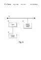
- FIG. 6illustrates one embodiment of an alternative structure for backup of data which may also be used in accordance with the present invention.
- a direct connection 60is established between the storage system 52 and the backup storage system 54 .
- the backup storage systemmay be a system as generally described in EMC Data Manager: Symmetrix Connect User Guide, P/N 200-113-591, Rev. C, December 1997, available from EMC Corporation of Hopkinton, Mass.
- the direct connection 60may be a high speed data channel, such as a SCSI cable or one or more fiber-channel cables.
- a usermay be permitted to backup data over the network 56 , or the direct connection 60 .
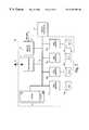
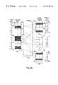
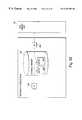
- FIG. 7shows a storage system 70 that may be used as the storage system 52 of FIG. 6 .
- the client 50may be connected to the storage device using a channel or bus 71 .
- the channel for communication with the client 50can be any suitable connection such as a Small Computer System Interface (“SCSI”) or Enterprise Systems Connection Architecture (“ESCON”). While only one communication channel 71 into the storage system 70 is shown in FIG. 7, other channels may be included.
- SCSISmall Computer System Interface
- ESCONEnterprise Systems Connection Architecture
- the host adapter 72is responsible for managing and translating read and write requests from the host computer (e.g., client 52 or backup storage system 54 ), which are based on the virtual disk structure (e.g., from the file system or logical volume manager level), into one or more requests corresponding to how data is stored on the actual physical storage devices 76 a - 76 d of the storage system 70 .
- the host adapter 72implements at least some of the array management software 23 functions of FIG. 2 .
- the host adapter 72can be implemented in any of a number of ways, including using a general purpose processor or a custom hardware implementation.
- multiple host adaptersmay be included to facilitate having additional I/O channels for the storage system 70 .
- the host adapter 72communicates with the other components of the storage system 70 using bus 73 .
- the bus 73may be any suitable communication element, including use of SCSI, ESCON, and other bus protocols.
- Access to the physical storage devices 76 a - 76 dis controlled through the use of disk adapters 75 a - 75 d .
- the disk adapter 75 a - 75 dcan also be implemented using a general purpose processor or custom hardware design. In the embodiment illustrated in FIG. 7, a disk adapter is provided for each physical storage device.
- a disk adaptercan, of course, have more than one storage device attached to it.
- disk adaptersmay include secondary connections to the physical storage devices of another disk adapter. This permits recovery from failure of one disk adapter by shifting its functions to the second disk adapter.
- reading and writing to the physical storage device 76 a - 76 d through the disk adapters 75 a - 75 dis facilitated through use of a cache 74 .
- the cache 74may be a random access memory having greater speed than the disk drives.
- the read requestcan be fulfilled more quickly by taking the data from the cache 74 .
- the data to be writtencan be stored in the cache. The other components of the system can proceed, while the data is written from the cache to the applicable physical storage device.
- Any of a variety of mechanismscan be used to implement and manage the cache.
- An example of such a mechanismis included in U.S. Pat. No. 5,537,568, entitled “System for dynamically controlling cache manager maintaining cache index and controlling sequential data access,” issued on Jul. 16, 1996.
- writesmay be accomplished through the cache using any of a variety of mechanisms and strategies.
- One mechanism for writing from the cacheis to store the data to be written in the cache, and mark a “write pending” bit. When the write pending bit is encountered, the applicable data can be written to the disk. This technique is described generally in U.S. Pat. No. 5,341,493, entitled “Disk storage system with write preservation during power failure,” issued on Aug. 23, 1994.
- the cachemay be divided into more than one area.
- the cachemay include an area 74 a for storing data being read or written from physical storage devices 76 a - 76 d .
- the cachemay further include a “mailbox” area 74 b .
- the mailbox area 74 bmay be used to facilitate communications among the disk adapters 75 a - 75 d and with the host adapter 72 .
- each disk adaptermay have its own area within the mailbox 74 b .
- Each of the disk adapters 75 a - 75 dcan post or read information from the applicable mailbox area 74 b , to communicate status and other information.
- a remote adapter 78may also be attached to the bus 73 of the storage system 70 .
- the remote adaptermay be employed for communication with remote data facilities (“RDF”), for example, connection to another storage device to maintain a mirror redundancy group.
- RDFremote data facilities
- One form of RDF link and method of implementationis described in various publications available from EMC Corporation, including SYMMETRIX Remote Data Facility Product Manual, P/N 200-999-554, rev. B, June 1995. RDF embodiments are also described in U.S. Pat. No. 5,544,347 (Yanai) which is hereby incorporated herein by reference in its entirety. It should be appreciated, however, that the present invention is not limited to the use of RDF or to a system that employs SYMMETRIX disk arrays, and can be employed with any of numerous other types of storage systems.
- a service processor 77may be coupled to the bus 73 of the storage system 70 .
- the service processor 77may include a display, keyboard and other I/O devices to permit an operator to use the service processor 77 for configuring the components of the storage system 70 and for running or initiating diagnosis and maintenance facilities.
- a computer systemincludes a host domain that has at least one host computer.
- the computer systemalso includes a storage domain, coupled to the host domain, that comprises a plurality of primary storage devices, a secondary storage device and a switched network coupled to the primary storage nodes and to the secondary storage node.
- a computer systemincludes a plurality of host computers, each of the host computers constituting a different platform.
- the computer systemfurther includes a plurality of primary storage devices, each being associated with at least one of the host computers.
- the systemalso includes a secondary storage device, coupled to a plurality of the primary storage devices, the secondary storage device being configured to receive backup data from each of the host computers.
- a method of transferring, data from a primary storage node to a secondary storage nodeis disclosed.
- a connectionis automatically established from one of the primary storage elements to a secondary storage element, for transferring data to the secondary storage element.
- Datais transferred from the primary storage element directly to the secondary storage element over the first connection.
- a method of sending a copy of data from a storage element of a computer systemis disclosed.
- the datais first formulated into an abstract block set.
- the abstract block setis transmitted.
- the steps of formulating and transmittingmay be performed sequentially or concurrently.
- a method of storing a logical objectis disclosed.
- the logical objectis formulated into an abstract block set and stored.
- a storage deviceincludes a memory and means for transmitting an abstract block set from the memory.
- a secondary storage systemincludes a secondary storage media and means for storing an abstract block set on the secondary storage media.
- a computer readable mediastoring a logical object.
- the mediaincludes a plurality of data blocks, each storing on the readable media a portion of data from the logical object, and a metadata segment, stored on the readable media, to identify the order of data blocks in the logical object.
- a method of generating a backup for a logical objectis disclosed.
- data blocks of the logical object that have changed since an earlier point in timeare identified.
- the identified data blocksare stored as a differential abstract block set.
- a storage deviceincludes a memory, means for identifying data blocks that have changed since an earlier point in time and means for transmitting a differential abstract block set from the memory.
- a method of forming an updated abstract block setis disclosed.
- a full abstract block setis provided.
- a differential abstract block setis also provided. The full abstract block set and the differential abstract block set are combined to form the updated abstract block set.
- a method of forming an updated backup of a logical objectis disclosed.
- a first backup of the logical objectis provided.
- a differential backup of the logical objectis also provided, the differential backup including a plurality of backup data blocks that have changed since the first backup was formed.
- the backup data blocksare added to the first backup and metadata identifying an order of data blocks in the updated backup is added.
- a secondary storage deviceincludes a secondary storage media and a controller programmed to combine a first backup and a differential abstract block set to form a full abstract block set.
- a method of copying a logical objectis disclosed.
- a set of storage segments of a computer storage deviceare identified, each of the identified segments including data from at least one physical block of a logical object.
- the identified storage segmentsare copied.
- at least one of the copied storage segmentsincludes a plurality of the physical data blocks.
- the size of the storage segmentis not necessarily the same as the size of individual physical data blocks.
- a method of creating a backup of a logical objectis disclosed.
- a set of backup segmentsis received, each backup segment including at least one physical block of a logical object.
- the received storage elementsare stored, at least one of the storage segments including a plurality of the physical data blocks.
- a computer readable mediastoring a backup copy of a logical object.
- a plurality of data segmentsare stored on the readable media, each data segment including at least one datablock of the logical object, and at least one of the data segments including a plurality of the logical data blocks.
- This embodimentfurther includes a metadata segment, stored on the readable media, to identify data blocks of the logical object in the data segments.
- the data segmentmay, for example, be a track including a plurality of fixed size blocks.
- a computer storage systemincludes a computer storage device that includes a plurality of physical storage segments (which, in one embodiment, is a track) each storing at least one datablock.
- the systemfurther includes means for identifying a set of storage elements, each storage segment of the set including at least one physical block of a logical object and means for transmitting the identified storage segments.
- a method of backing up a logical object at a fixed point in timeis disclosed.
- a set of storage segments that include logical data blocks of the logical objectare identified. These storage segments are copied to a backup storage device, out of order from the order of storage segments or logical data blocks appearing in the logical object.
- the copying stepif a storage segment that includes a physical block of the logical object is to be modified, that storage segment is immediately backed up.
- the storage segmentsmay (but need not) correspond in size to the size of data blocks.
- a computer storage systemincludes a computer storage device that has a plurality of storage segments.
- the systemfurther includes means for identifying a set of the storage segments that includes logical objects, logical data blocks; means for copying the identified storage segments, out of order from the order of logical data blocks and the logical object; and means for immediately copying storage segments to the backup storage device if an attempt is made to modify a physical block of the storage segment.
- a method of copying a logical object to a primary storage deviceis disclosed.
- a copy of the logical objectis provided.
- Physical blocks of memory in the primary storage deviceare allocated for storing the logical object.
- a map of the data blocks of the copy of the logical object to the physical blocks of the primary storage deviceis created.
- the data blocksare copied to the physical blocks, based on the map.
- a method of copying a logical object to a primary storage deviceis disclosed.
- an abstract block set copy of the logical objectis provided.
- Physical blocks of memoryare allocated in the primary storage device to store the logical object.
- the data blocks of the copy of the logical objectare mapped to the physical blocks of the primary storage device and the data blocks are copied to the physical blocks based on the mapping.
- a computer storage deviceincludes a memory including a plurality of physical data blocks.
- the devicefurther includes means for storing the data blocks of an abstract block set to the physical data blocks, based on a mapping of the data blocks to a set of the physical data blocks.
- a method of copying a logical objectis disclosed.
- a set of storage segments that includes the logical data blocksare identified.
- the storage segmentsmay correspond to the logical data blocks, or may be of a different size.
- the identified storage segmentsare copied to a second storage device, out of order from the order of logical data blocks in the logical object.
- a method of copying a logical objectis disclosed.
- a set of storage segments that includes the logical data blocks of the logical objectare identified.
- the identified storage segmentsare copied to a second computer storage device in parallel.
- Metadatais provided to identify the order of data stored in the identified storage segments in the logical object.
- a method of backing up a logical object that includes a plurality of logical blocksis disclosed.
- a first and a second backup mediaare provided.
- each backup mediais a digital storage tape.
- Logical blocksare written to the first and the second backup media in parallel.
- a secondary storage deviceincludes a plurality of storage components and means for writing portions of an abstract block set to the storage components, in parallel.
- a method of restoring a logical objectis disclosed.
- a first and a second portion of a copy of the logical objectare provided.
- Data blocks stored in the first portion and data blocks stored in the second portionare read in parallel.
- the logical objectis restored from the read data blocks.
- a secondary storage deviceincludes means for reading data from a plurality of storage components, in parallel, and means for providing the read data to another device as an abstract block set.
- FIG. 1illustrates an example of conversion of application level data to storage in a physical system and vice versa.
- FIG. 2Aillustrates an example of the relationship between logical volumes and physical storage devices.
- FIG. 2Billustrates an example of mapping a logical file onto a physical storage system.
- FIG. 2Cillustrates another example of mapping a logical object onto a physical storage device.
- FIG. 3Aillustrates an example of mirroring on different physical storage devices.
- FIG. 3Billustrates an example of redundant parity information on physical storage devices.
- FIG. 4illustrates an example of multiple redundancy groups within a single array of storage devices.
- FIG. 5illustrates an example of a backup storage system.
- FIG. 6illustrates one embodiment of a backup storage system that includes a mechanism for direct backup of data on the primary storage system.
- FIG. 7illustrates an example of a storage system.
- FIG. 8illustrates one example of a computer storage system structured to have an enterprise host domain and an enterprise storage domain or network, according to one embodiment of the present invention.
- FIG. 9illustrates another example of a computer system including an enterprise host domain and an enterprise storage domain, according to one embodiment of the present invention.
- FIG. 10illustrates one embodiment of a method of copying or backing up a logical object.
- FIG. 11Aillustrates one example of some of the components of a computer system that includes a host domain and a storage domain, according to one embodiment of the present invention.
- FIG. 11Billustrates another embodiment of components of a computer system that is divided into a host domain and a storage domain, according to one embodiment of the present invention.
- FIG. 12illustrates one embodiment of a method for copying or backing up data in a computer storage system.
- FIG. 13illustrates one example of mapping a logical object onto a physical storage device and formation of an abstract block set for copying or backup, according to one embodiment of the present invention.
- FIG. 14illustrates one embodiment of a method for forming an abstract block set.
- FIG. 15illustrates one embodiment of a method for copying or restoring a logical object from an abstract block set.
- FIG. 16illustrates one example of combining two forms of metadata for a logical object into a remapping table for restoring the logical object to a new area of memory.
- FIG. 17illustrates one example of storage of a logical object across a computer system and formation of an abstract block set using physical backup segments corresponding to track size, according to one embodiment of the present invention.
- FIG. 18illustrates an example of one embodiment of metadata for an abstract block set that has a physical backup segment granularity larger than the size of a datablock.
- FIG. 19illustrates one embodiment of a method for backing up a logical object while preventing updates to the logical object during the backup.
- FIG. 20illustrates one example of a system that includes markers for physical backup segments, permitting avoidance of updating information within a logical object during a backup process, according to one embodiment of the present invention.
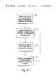
- FIG. 21illustrates one embodiment of a method for performing a differential backup.
- FIG. 22illustrates one embodiment of tracking changes at the physical level of a system, and converting those changes to logical information.
- FIG. 23illustrates an example of performing a differential backup on a logical object, according to one embodiment of the present invention.
- FIG. 24illustrates one example of forming full and differential logical backup objects for backup of a logical object, according to one embodiment of the present invention.
- FIG. 25illustrates one example of combining an abstract block set and a differential abstract block set into a single full abstract block set, according to one embodiment of the present invention.
- FIG. 26illustrates one embodiment of a method for combining differential abstract block sets with a full abstract block set to produce a new full abstract block set.
- FIG. 27illustrates one example of a system for backing up data on a primary storage node, using a secondary storage node, according to one embodiment of the present invention.
- FIG. 28illustrates one embodiment of a state diagram for any synchronous transfer of data for copying or backup.
- FIG. 29illustrates one embodiment of a state diagram for asynchronous restore of a backed up logical object.
- FIG. 30illustrates one embodiment of a system and data flow within a system for sending copy of backup information from a primary storage node.
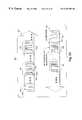
- FIG. 31illustrates one embodiment of a method for sending data from a primary storage node.
- FIG. 32illustrates one embodiment of a structure and data flow for control of writing information to a backup media.
- FIG. 33illustrates one example of a tape media written with backup abstract block sets.
- FIG. 5 and FIG. 6may be viewed as focusing on a network model for storage, or a “network-centric” system. In such a system, the focus of data transfer is movement of logical data across a network. Moreover, the storage system 52 and backup storage system 54 are typically associated with a single client or host 50 architecture.
- An alternative modelfocuses on a separation of the client or host domain and the storage domain.
- FIG. 8illustrates one example of a system which segregates the host domain from the storage domain.
- a number of host computers 80are included in an enterprise host domain 80 a .
- the host computerscan be any type of computers, operating systems and data management applications.
- one host computer 80may be a Hewlett Packard 9000 computer system running an HP-UX Operating System.
- Another host computer 80can be a Sun Spark Station running a Solaris operating system.
- the combination of a host, operating system and applicable data management applicationis referred to as a “platform.”
- Each of the host computers 80may constitute a different platform interfacing with the storage network 89 .
- the host computers 80 in the enterprise host domain 88may be connected over a network.
- This networkmay include switching nodes 81 , although any other form of network may be used.
- the host computers 80are coupled to the enterprise storage 89 through a network or directly to primary storage nodes 82 .
- a primary storage nodeis a memory device that can store significant amount of data for use by the host 80 .
- a Symmetrix systemsuch as the one described above with respect to FIG. 7, may be used as a primary storage node, although this is not intended as limiting.
- each host computeris coupled to a subset of primary storage nodes 82 , for use as a main memory for that host computer.
- host computer 80 ais coupled directly to primary storage node 82 a .
- the host computer 80 amay rely on primary storage node 82 a for most of its memory intensive functions, such as for accessing a very large database.
- the primary storage nodes 82may also be coupled together through a network.
- the networkincludes link 85 and switch network 84 .
- the switch network 84may, for example, be a fiber channel network.
- the link 85may be an RDF link over an ESCON line.
- the network between primary storage nodesmay serve two purposes.
- the networkmay permit transfer of data between primary storage nodes.
- a database being manipulated by host 80 aand stored in primary storage node 82 a , may be transmitted to primary storage node 82 b for use by host 80 b .
- the computational resources of the host 80 a , 80 b , and the available bandwidth in the enterprise host domain networkcan be preserved.
- the enterprise storage network 89may also include a secondary storage node 87 .
- the secondary storage nodemay be used for backup functions, hierarchical storage management, virtual disks and other functions.
- the secondary storage node 87may be coupled to a tape storage unit 83 .
- the secondary storage node 87would coordinate sophisticated transfer of data from the primary storage nodes 82 to the tapes stored in a tape storage unit 83 . (Other embodiments may use additional or alternative media for secondary storage.)
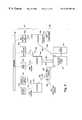
- FIG. 9illustrates one embodiment of a computer network constructed according to one aspect of one embodiment of the present invention.
- an enterprise host domain 97is provided.
- the enterprise host domain 97includes a variety of host computers 90 a - 90 c .
- the host computersmay include different platforms and different corresponding mechanisms for accessing and storing data in the memory.
- host computer 90 ais a Hewlett Packard HP 9000 computer.
- Host computer 90 cis a Sun Spark Station which may be running a Solaris Operating System.
- the host computersmay communicate with each other across a network 96 .
- Such a networkcan be one of many computer networks known and applied for connecting computers.
- each host computer 90 a - 90 eis connected to a primary storage node 92 a - 92 c .
- each primary storage node 92 a - 92 cis an iterative cached disk array, such as a Symmetrix memory system such as the one described above with respect to FIG. 7, although this is not intended to be limiting.
- host computer 90 ainterfaces primarily with storage node 92 a .
- host computer 90 buses primary storage node 92 a as a primary source of its data.
- the host computer 90 ais connected to the primary storage node 92 a over a high speed fiber channel 91 a .
- the host 90 bis connected to the primary storage node 92 a over a standard SCSI connection.
- Each of the hosts 90 a and 90 bare coupled to the same primary storage node 92 a .
- Other mechanismscould be used to connect the host computers 90 a - 90 e to the primary storage nodes 92 a - 92 c .
- a complete switched networkcould be employed, for any of the host computers to access any of the primary storage nodes 92 a - 92 c.
- Each of the primary storage nodes 92 a - 92 cmay also be coupled together using a network.
- the only link among the primary storage nodesis an ESCON remote data facility (ESCON “RDF”) link 93 g .
- ESCON “RDF” link 93 gSuch a link may be used for transferring of data or maintaining a mirror of data either on-line or as a periodically updated mirror.
- Such a linkmay be implemented as described in U.S. Pat. No. 5,544,347 (Yanai), which is incorporated herein by reference in its entirety.
- Each of the primary storage nodes 92 a - 92 cmay be coupled together using any other mechanism.
- an RDF linkcould be used to fully connect each of the primary storage nodes 92 a - 92 c .
- a switch networkcould be used, assuming that the network is of sufficiently high speed to support the data operations among the primary storage nodes 92 a - 92 c.
- the storage network 98 in the embodiment of FIG. 9further includes a secondary storage node 94 .
- the secondary storage nodeis used for backup (and other) functions, for example by storing and restoring information to and from a tape library 95 .
- each of the primary storage nodesis connected or connectable (by a network) to the secondary storage node 94 .
- primary storage nodes 92 b and 92 care coupled to secondary storage node 94 each using an RDF link ( 93 c and 93 d respectively) which may be implemented as described above.
- the primary storage node 92 ais connected (together with other primary storage nodes, not shown) to the secondary storage node 94 over a switched network, which will permit each of the systems to access the secondary storage node 94 .
- the primary storage nodes 92 a - 92 c and the secondary storage device 94may be physically located at great distances apart.
- the storage component of the computer systemis elevated to a status of equal importance.
- the storage components of the systemare capable interacting with each other with less involvement from the host domain. For example, it may be desirable to permit mirroring across one or more primary storage nodes. Similarly, data objects may need to be copied from one primary storage node to another primary storage node. Where additional levels of backup are desirable, the primary storage nodes may also transfer data to a secondary storage node for backup purposes. The primary storage nodes may, correspondingly receive data from the secondary storage nodes for restore.
- some or all of the resource intensive functions in such a systemcan be moved out of the host domain. Certain embodiments following this model can preserve host domain resources, increase scalability of memory (by adding to the storage domain without as much concern about affect on host domain resources) and reduce dependence on the particular platforms of the hosts in the host domain.
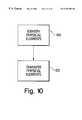
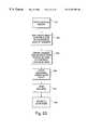
- FIG. 10illustrates, at a very basic level, how data is moved in one such system.
- the physical elementse.g., data blocks
- those physical elementsare transferred.
- the physical elements that are to be copiedare identified at step 100 .
- the location of where the elements are to be copied toare identified. For a copy between primary storage nodes, this may involve identifying the copy from locations and the copied to locations. For a backup, this involves identifying the copy from locations and may be as simple as determining what tape or other backup storage element will receive the backup data.
- the physical elementsare transferred from the identified copy from locations to the identified copy to locations.
- the physical elementsare copied to tapes. (Although reference is made to tapes as secondary storage, this is not intended to be limiting. Any other storage media may be used).
- the step 100can, however, be extremely complicated. In many cases, it is not desirable to copy the entire contents of a primary storage node. Rather, only a subset of the physical elements in the primary storage node may need to be copied. As one example, consider backing up a database stored in primary storage node 92 a of FIG. 9 . This database may occupy only a small portion of the total data stored in the primary storage device 92 a —in fact, there may be an extremely large segment of data accessible primarily by the host computer 90 b which host 90 a may not even be capable of reading (because it is a different platform than the host computer 90 a ).
- the step 100requires mapping the logical object onto the physical elements in the primary storage node 92 a in order to identify the physical elements that need to be copied from 92 a . As described above with reference to FIG. 2C, these physical elements may be located in disparate locations within the primary storage device.
- the step 102may similarly be complicated. Even after all of the physical elements in the primary storage device have been identified, simply transferring the physical elements is insufficient. The relationship between the physical elements may need to be preserved for the copied or backed-up logical object to be read by the host computer coupled to the receiving primary storage node.
- One mechanism for use of mapping a logical object to physical elements and preserving the logical relationship between those physical elementsis discussed below. This is not intended as limiting with respect to other aspects of the present invention.
- the primary storage nodes and the secondary storage nodes in the networkmay include sufficient intelligence to handle aspects of the data transfer process.
- the primary storage nodesmay be capable, at a minimum, of managing the transfer of identified physical elements in a logical object even when those physical elements are stored in disparate locations within the primary storage device.
- the computer systemmay include a storage management application (“SMAPP”) for managing manipulation of storage within the storage domain.
- SMAPPstorage management application
- the SMAPPcan be implemented using software on the host computers, primary storage nodes, a separate storage controller or in some combination of these, as described below with reference to FIGS. 11A and B, below.
- the storage management applicationcan be implemented using three primary components—a management component, server component and client component.
- the management componentcontrols configuration of the backup, control and monitoring of the backup and copying processes in the storage domain.
- the management componentalso tracks location of copies of logical objects in the storage system including, for example, what tape or tapes contain backups of each particular logical object.
- the server componentcontrols the hardware functions of the memory process, such as acts of mounting and dismounting tapes, opening and closing, reading and writing tapes and other memory media.
- the client component of the SMAPPhandles manipulation and identification of the backup or copy-from source.
- the client componentis responsible for identifying the applicable logical object (e.g., file system, file or database) and determining what operating system level (or logical volume manager level) physical elements are involved.
- an additional layer of mappingmay be performed within the storage domain at the primary storage element of 111 .
- the primary storage element 111is a Symmetrix product as described above, the identified physical tracks may be re-mapped within the primary storage element 111 .
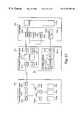
- FIG. 11Aillustrates one example of a portion of a computer system having a host domain and a storage domain.
- only one host 110is shown in the host domain.
- only three componentsare shown in the storage domain. These are the primary storage element 111 (which may be, for example, a Symmetrix disk array), a secondary storage element 112 and a tape library unit 113 .
- additional storage elementsmay be included, coupled together by a network.
- FIG. 11Ashows only one element from each of three different storage levels—host, primary storage element and secondary storage element.
- a storage management application (“SMAPP”) 114is primarily a resident on the host computer 110 .
- the host computerwould include an Application Programming Interface (“API”) which would permit management of copying, backup and restore (and other) operations.
- the storage management application 114 on the host 110includes a server component 115 b . Again, the host would include an API permitting management of server operations.
- the storage management application 114in this example, includes a client component 115 c . The client component would be responsible for identifying and manipulating logical objects and identifying (from the operating system or logical volume management level view of) the physical elements that comprise the logical object.
- the primary storage elementincludes an SMAPP interface 116 a .
- the secondary storage element 112includes an SMAPP interface 116 b .
- the copying of a logical object from the primary storage element 111 to the secondary storage element 112 in the embodiment shown in FIG. 11Amay proceed as follows. First, a “virtual circuit” or “connection” is set up between the primary storage element 111 and the secondary storage element 112 . This may be a virtual circuit established through a network coupling the primary storage element to the secondary storage element 112 (including a single RDF link between the primary storage element 111 and the secondary storage 112 , for example). In addition to establishing a physical connection between the nodes, the virtual circuit identifies a session for copying a series of data (comprising, e.g., the logical object) over the identified connection.
- the management component 115 a on the SMAPP 114 on the host computer 110may begin a backup session by instructing the primary storage element to establish a virtual circuit with the secondary storage element 112 .
- the actual establishment of the virtual circuitmay then be performed by the SMAPP interface 116 a of the primary storage element 111 in combination with the SMAPP interface 116 b of the secondary storage element 112 .
- the client component 115 c of the host computer 110identifies a logical object for backup.
- the client component 115 cthen maps that logical object to the operating system (or a logical volume manager level) set of physical elements. This mapping may be performed in one step.
- the client component 115 c of the host 110may then identify the elements for copying to the primary storage element 111 , as communicated through the SMAPP interface 116 a.
- the server component 115 b of the host 110would identify and mount the appropriate tapes in the tape library unit 113 .
- the server component 115 bperforms these commands by passing them to the SMAPP interface 116 b of the secondary storage element 112 , through the SMAPP interface 116 a of the primary storage element 111 , which then mounts the tapes.
- the actual performance of the backup processmay proceed, without further control by the host 110 of the host domain (except, in some embodiments, monitoring the process and managing the backup media, e.g., controlling changing of tapes in a tape drive).
- the primary storage element 111may copy the identified physical segments to the secondary storage element 112 .
- FIG.11Billustrates an alternative structure for control of the storage domain of a computer system according to the present invention.
- a storage network controller 118 ais connected to the host 110 , primary storage element 111 and secondary storage element 112 through a network 119 .
- This networkmay follow the TCP/IP protocol.
- the storage network controller 118 amay be any hardware, or hardware and software, combination capable of performing the requisite functions.
- the storage network controller 118 amay be a computer running a windows NT operating system, with suitable application software for performing the SMAPP functions.
- the SMAPP 118 b of the storage network controller 118 aincludes a management component and a server component.
- management of the hardware and mediacan be performed by the storage network controller 118 a , independent of the host computer 110 .
- the host 110includes an SMAPP 117 to perform client functions.
- logical to physical mappingis still performed in the host domain by the host computer 110 .
- the client component of the SMAPP 117is responsible for identifying logical objects and performing logical to physical mapping, this can be a sensible arrangement.
- the logical to physical mappingdepends on the particular host platform and the host necessarily has elements capable of performing the requisite mapping.
- the client componentcan be included in the storage network controller 118 a , or in a separate device capable of performing logical to physical mapping for one or more platforms. Where this is done, the identification and transfer of data for copying and backup purposes can be performed completely separately from the host domain. In many systems, however, it will be more efficient to use the memory mapping mechanisms (client component) on the host computer.
- the components of the SMAPP softwaremay be distributed across the primary storage elements in the storage domain, the secondary storage element or elements in the host domain or some combination thereof.
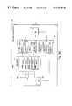
- FIG. 12illustrates one embodiment of a method for transferring a logical object according to a system such as the one shown in FIGS. 11A and 11B.
- a virtual circuitis established. As described above, this may correspond to establishing a physical connection between the element being copied from (e.g., a primary storage element) to the storage element being copied to (e.g., a secondary storage element).
- this step 120corresponds to establishing a session for performing the copying over the connection.
- the establishment and managing of the virtual circuitcan be performed by an SMAPP component resident on a host computer, storage network controller, or other device.
- the logical objectis mapped to identify the physical elements being copied from. For performing a backup, this would correspond to mapping an identified logical object at the application level to a set of physical elements at the storage level.
- this stepis straightforward. No actual mapping needs to take place. In other circumstances, such as the abstract block sets described below, a table or other structure may identify the mapping of portions of the physical elements to their order in the logical object. The actual mapping from the logical level to the physical level may have been performed at the time of the backup and saved.
- update to physical elementsis prevented. For example, if a database is being backed up from a primary storage element to tape, updates of the logical object should be prevented so that the backup can correspond to a single point in time.
- the copyingis from a backup tape to a primary storage element, the freezing of updating the physical elements is rather simple—the tape will not be written while it is being read from in the restore.
- a method for concurrent copying described belowmay be used to prevent the update of physical elements during the copying process.
- the copy-to memoryis managed.
- thismay correspond to mounting and disbounding the appropriate tapes, as well as managing the tape library, catalog information, as well as writing appropriate tape headers and trailers.
- thismay correspond to managing the receiving physical elements of the primary storage element being copied to.
- itmay involve setting up an appropriate storage area to receive the information.
- the actual physical elementsare copied.
- the copyingmay be done in the appropriate order for the logical object, such as when an ordinary data file is sent at the application level between two host computers.
- the physical data blocksmay be copied out of order, together with appropriate metadata identifying the correct order of the physical elements in the logical object. An embodiment of this type of system is described below.
- the physical elements of the logical object, in the copy-from memory,are unfrozen—allowing updates of the logical object.
- the backupis complete and the physical elements can be unfrozen.
- the virtual circuitmay be closed.
- an abstract block set structureas described more fully below.
- This type of structureis useful not only in the storage network architecture as described above, but has greater applicability.
- the abstract block set conceptmay be employed in any system where logical objects are copied from one storage element to another storage element.
- the abstract block setcan also be used to particular advantage when used for backing up and restoring data from a secondary storage device, such as a tape drive.
- the abstract block setpermits storage of the data blocks in any order.
- the abstract block setincludes information about the ordering of those elements.
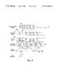
- FIG. 13illustrates one example of an abstract block set.
- a logical object 130includes a number of data blocks 130 a - 130 f (ordinarily a logical object may include substantially more data blocks, FIG. 13 being by way of illustration only).
- the logical objectis stored in a physical memory 131 , as generally described above with reference to FIG. 2 C.
- Each columnmay be viewed as a track (although this is not intended as limiting), and each row as a row of blocks within the tracks.
- the logical data blocksmay be scattered throughout the physical memory 131 .
- An abstract block set 132may be constructed from the data blocks 130 a - 130 f .
- the data blocksare not necessarily stored in the same order as they appear in the logical object. In this example, they are in a random or pseudo-random order. (As a practical matter, the order of data blocks may reflect the way that the data blocks are stored in a physical storage 131 . For example, if data blocks A and B are stored on one track they would probably be read and written to abstract block set 132 in the order they appear on that same track.
- the abstract block set 132 appearing in FIG. 13is for illustration only.
- the abstract block set 132includes metadata 133 .
- the metadatais any recorded information that provides a mechanism to reconstruct the order of logical data blocks as they appear in the logical object 130 .
- the metadata 133includes an ordering of logical block elements (the column labeled LBEL) with the physical element location.
- logical block element 1has metadata corresponding to the address of that logical data block in the physical memory 131 —the physical element address.
- each of the stored data blocks 132 a - 132 f in the stored abstract block set 132would need to include a label with the corresponding physical address.
- ADDR-Athe physical address of the data blocks 132 a - 132 f
- This data blockcould then be found in the abstract block set 132 by examining the physical addresses of the data blocks 132 a - 132 f (the physical addresses appearing within the data blocks 132 a-f ), until the appropriate block is found.
- the metadata 133could just describe the order of the logical block elements in the abstract block set 132 .
- the second column of the first row of the metadata 133could indicate that the first logical data block (corresponding to A) is stored as the sixth block in the abstract block set 132 .
- the first column of the metadata 133is not required.
- the order of the elements in the second columncorresponds to their location within the logical object 130 ; the address for the first logical block element appears first in the table, the address for the second logical data block appears as the second entry in the second column, etc.
- Metadata 134illustrates another way of storing the metadata associated with the logical block 132 .
- a first columncorresponds to the ordering of data blocks as they appear in the abstract block set (as above, unnecessary as the order that the rows appear implies this information—the first row is the first block in the abstract block set).
- the second columnindicates the position of the data block within the logical object 130 .
- the first entry in the first row of the metadata 134corresponds to the data block 132 a of the abstract block set 132 .
- the second columnhas a “2” indicating that this data block 132 a is the second data block of the logical object 130 .
- the last column of the metadata 134provides the physical address for the applicable data block in the physical memory 131 .
- Metadatamay be tracked for extents (sequences of blocks) rather than individual blocks.
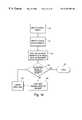
- FIG. 14illustrates one embodiment of a method for copying a logical object to form an abstract block set as described above.
- the logical objectis identified.
- the logical objectcan be any logical entity, such as a database, a segment of a database, file, or file system.
- the logical block elements or logical data blocks of the logical objectare identified. This may precede as generally described above.
- the logical block elementsare mapped to physical backup segments.
- the physical backup segmentsmay correspond to the physical elements that store the logical data blocks.
- the mapping step 142may include formulating that information into whatever format the metadata is stored in.
- the steps 140 - 142may be performed by a client component of a storage management application. In some systems, this may require the resources of a host computer.
- the remainder of the copying processmay proceed without significant involvement of the client component of the storage management application.
- step 144is to determine whether all physical backup segments have been copied. If so, the copying process is complete at step 145 .
- the next available backup segmentis copied at step 146 . As described above, this copying need not be performed in the order appearing in the logical object identified at step 140 .
- the metadatamay be updated after the applicable backup segment has been copied into the medium holding the abstract block set.
- this form of metadata(but not the form shown at 133 of FIG. 13 ). This may not occur until the applicable backup segment is copied to the medium storing the abstract block set because, until that time, the order of appearance for the applicable physical backup segment is not known.
- FIG. 15illustrates one embodiment of a method for restoring an abstract block set to a memory system, such as the primary storage node described above.
- the metadata for the abstract block setis retrieved. This may be in the form of a map for the abstract block set such as those illustrated at 134 of FIG. 13 or may be a set of labels associated with the individual data blocks stored in the abstract block set, such as in table 133 of FIG. 13 .
- memoryis allocated in the target storage device for receiving the logical object.
- the amount and configuration of the memory required to receive the logical objectcan be determined from the metadata for the abstract block set.
- the metadatawill include sufficient information to determine the characteristics of storage required. For example, in the event that the abstract block set indicates use of fixed size blocks, the total number of (fixed size) blocks required to store the logical object can be determined by the number of entries and a metadata table or maybe separately stored as a part of the metadata for the abstract block set.
- dummy metadatais created for the newly allocated physical memory for the logical object to be restored.
- the resultcan be a new table such as the one shown at 133 of FIG. 13 .
- a re-mapping tableis created.
- the re-mapping tablespecifies a correspondence between the data blocks of the abstract block set is the source of data and the allocated data blocks in the physical memory.
- An example of a re-mapping tableis described with reference to FIG. 16 . Although shown in tabular form, the data can be stored in other forms and formats.
- step 154it is determined whether all of the physical backup segments have been restored from. If so, the restore is complete at a step 155 .
- the next physical backup segmentis retrieved.
- the location and the newly allocated memory for receiving the logical objectis determined. This can be done by examining the re-mapping table created at step 153 .
- the retrieval of segments done at step 156need not be in any specific order.
- the re-mapping tablepermits restoration of the entire logical object even when the data blocks are provided in a random order.
- Step 158the data from the physical backup segment is restored to the appropriate locations. Steps 154 - 158 then continue until all of the data blocks have been properly restored.
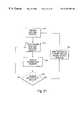
- FIG. 16illustrates an example of creation of a re-mapping table.
- creation of re-mapping tableis possible, depending on how the metadata is formulated and stored for the abstract block sets.
- metadata 160is provided for the abstract block set that is serving as the source for the restore. This table corresponds to the metadata 133 of FIG. 13 .
- FIG. 16also illustrates dummy metadata 161 for the allocated memory that will receive the restored logical blocks of the restored logical object.
- the formatis the same as that for the metadata 160 , except that different addresses (potentially on a completely different storage element) are provided.
- the first logical data blockshould be stored at the physical location specified at ADDR-AA.
- the remapping table 162specifies the physical location from the data in the abstract block set and the destination for the that logical data block.
- re-mapping table 162could simply map the sequential location in the abstract block set being restored from to the physical address or to the sequential location on the receiving storage element.
- each entry in the metadata remapping tablemay correspond to extents in the physical memories restored from and to.
- the backup, copy and restorewas performed at the data block level.
- the physical backup segmentcorresponded in size to the size of a data block. Those data blocks that are part of the logical object, and only those data blocks were copied for backup and were restored.
- Granularity of the physical backup segmentsneed not, however, correspond to the granularity of the data blocks.
- a trackmay store a number of physical data blocks.
- not all of the data blocks within a trackare necessarily a part of the same logical object.
- only two of those data blocksmaybe a part of a logical object, the other two data blocks being unused or part of a different logical object.
- Backing up of data in a logical objectmay, however, be performed at the track level rather than the physical data block level. The result would be an abstract block set that includes some data blocks that are not a part of the logical object.
- the physical backup segment sizecorresponds to the size of a track.
- the actual physical data blocks that may store the data of a logical objectare smaller, e.g, four data blocks per physical backup segment of one track.
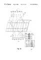
- FIG. 17illustrates the concept of a physical segment size (here, a track) that is larger than the size of the physical data blocks.
- a logical object 170is stored on a physical device that includes tracks. Each track holds (in this example) up to three data blocks.
- the logical object 170is viewed as a continuous file. This file may be partitioned into a number of logical data blocks, shown in FIG. 17 as vertical bars within the logical object 170 .
- a file system image 171holds that data in each of the logical data blocks of 170 .
- the order of the logical data blocks at the file system levelmay not correspond to the order of their appearance within the logical object 170 .
- a mapping processmaps the logical data blocks to appropriate locations within the file system image 171 .
- the file system image 171may be mapped to a logical volume of hypervolume level 172 a - 172 b.
- the logical volumes 172 a-bare then stored on a physical storage device in hypervolumes 173 n and 173 o . As shown in FIG. 17, the hypervolumes may not be physically adjacent. (Of course, as described above, other techniques for mapping the logical data blocks of the logical object 170 to the physical storage device are possible and within the scope of the present inventions.)
- the first hypervolume 173 nstores data across seven tracks 173 a - 173 g . These tracks may, but need not, be contiguous segments of memory.
- the entire track 173 bcontains physical data blocks that are part of the logical object 170 (given the assumption that only three data blocks are stored per track).
- the track 173 dincludes only one data block that is a part of the logical object 170 —the other data blocks in the track 173 d either being unused or containing data belonging to a different logical object.
- some of the tracks within the hypervolume 173 ndo not contain any data from logical object 170 , e.g., tracks 173 a , 173 c and 173 f .
- the hypervolume 173 osimilarly contains some tracks that include data from the logical object and some tracks that do not.
- the physical segments that would be part of a backup processwould include tracks 173 b , 173 d , 173 e , 173 g , 173 i , and 173 k . These tracks make up the physical backup segment set (here, a “trackset”) that would be copied when the logical object is backed up. Since, in the example of FIG. 17, the physical backup segment granularity is by tracks, this may be referred to as a track set.
- the track set for a backup of logical object 170would include tracks 174 a - 174 g , which in turn correspond to those of the physical tracks 173 a - 173 m that include data blocks from the logical object 170 .
- identification of the physical backup segmentsincludes not just identifying the logical block elements but using the identified logical block elements and their physical data block locations to determine the physical backup segment set, e.g., the track set 174 a - 174 g of FIG. 17 .
- the copying of the available backup segments at step 146would involve copying the larger granularity segment (e.g., a complete track rather than just the particular physical data blocks on the track).
- the physical backup segmentse.g., tracks
- the physical backup segmentsmay be copied in any order.
- an abstract block set signature track 175may be stored.
- This signature trackincludes the metadata for the abstract block set.
- specification of the metadata for the abstract block setmay include a specification of the particular data blocks in the abstract block set and their location within the logical object 170 .
- FIG. 18shows one example of metadata 180 for an abstract block set that has a physical granularity greater than the size of the physical data block.
- the location of each data blockis specified.
- the first columnis a specification of the data block within the logical object—e.g., first, second, third, fourth data block.
- the second column of the metadata 180specifies the physical address of that logical object.
- that physical addressincludes a specification of where within the physical backup segment the applicable data block is located. For example, this information may be included as an offset within the physical backup segment.
- an address of dd:cccc:h:offsetincludes a specification of the physical backup segment (dd:cccc:h), which in this example specifies a track and a location within that physical backup segment (track), and an offset.
- the first row of metadata 180corresponds to the first logical data block in the logical object.
- the second row of the metadata 180specifies the same address, but has an offset of 1—it is a data block appearing in that physical backup segment (track) immediately following the data block corresponding to the first logical data block of the logical object.
- the track that includes the first two logical data blockshas additional room within the track, but that those additional data blocks in the track are not a part of the logical object. Accordingly, there is no entry in the metadata table 180 specifying a corresponding logical data block for that portion of the track. (In an alternative embodiment, of course an entry could be made which indicates that that portion of the track is unused in this abstract block set.)
- Restoring (or copying) from an abstract block set that has a physical backup segment granularity larger than the data block sizemay proceed as generally prescribed above with reference to FIG. 15 .
- the locations of the logical data blocks within the backup segmentare identified—including determining whether any portions of that backup segment may be omitted.
- step 158only those data blocks that are actually used in the logical object are restored.
- Selecting a physical backup granularity larger than the size of data blockcan require transfer of more memory than if the physical backup segment size is the same as the data block—some unused data blocks are included as a part of the copy or backup process.
- a larger physical granularity sizecan, however, result in certain advantages. For example, less overhead may be required in the copying process—fewer segments for copying need to be specified. In addition, other resources may be preserved. For example, if high demand memory is used for storing information identifying the physical backup segments to be copied, less such memory is required. In the event that the physical data blocks of logical objects are prevented form being updated during a copy or backup process, this can be done by protecting updates at the physical backup segment level rather than the data block level—again requiring less overhead. In some systems, this can reduce the complexity of avoiding updates. Some embodiments of the invention employing different physical backup granularity than data block size may achieve some or all of these advantages, depending on the context and system in which it is implemented. None of these advantages is intended to limit the scope of the invention, which is defined by the claims below.
- certain systems embodying one or more aspects of the present inventionwill allow copying or backup, of a logical object at a specified point in time. To do this, updates to the logical object need to be prevented during the copying or backup process. There are many ways to do this, including taking the application that uses the logical object off-line until the backup process is complete. While certain embodiments of the present invention will use this and other techniques, it may be advantageous to be able to continue processing during the backup.
- FIG. 19illustrates one embodiment of a method for performing a backup while preventing updates to those physical data blocks that are part of the logical object being backed up.
- the logical object(or system using the logical object) is quiesced.
- One wayis to take the application off-line, and update the logical object off-line. This prevents any further updates (or reads) to the applicable logical object. Taking the application off-line can be undesirable—resulting in loss of time and system availability.
- An alternative way of quiescing a systemis to place the application in on-line backup mode. For example, if the application is using an oracle database, writes to the database can be stored in a re-do log, rather than actually writing the data to a physical storage system. When the application is brought back to on-line mode, the updates to the logical object that are stored in the re-do log may then be applied to the current copy of the logical object.
- those physical backup segments that contain data from the logical objectare marked for copying. This may be done in a number of ways. For example, a bit may be associated with each potential physical backup segment in the system. The bit may be set to a “one” if the corresponding physical backup segment is part of a logical object to be copied. Of course, the methods for identifying the physical backup segments that are part of the abstract block set being copied can be used. As just one example, a list of the physical backup segments could be maintained.
- FIG. 20illustrates an example of a system having bits associated with physical backup segments.
- the physical backup segment sizeis a track of the physical memory 28 , such as column 28 b .
- a logical object 27is stored across the physical memory 28 .
- a series of bits 29is associated with the tracks of the physical memory 28 .
- a oneis set for those tracks (physical backed up segments) that are part of the track set for the logical object.
- the second bit of the bit set 29is set at one, reflecting the fact that track 28 b is included in the track set for the logical object 27 . If the physical backup segment granularity were a data block, a bit could be associated with each data block—at higher overhead.
- the application using the logical objectcan be returned to the active state. This may, for example, involve the step of returning the application to on-line mode from off-line mode. If the application was held in on-line backup mode, any elements in the re-do log may be applied to updating the logical object.
- a step 194it is determined whether there is a hit on a physical backup segment that is included in the backup segment set in the abstract block set. If so, that segment is copied out of turn—and before the update is made. After the segment has been copied, that segment can be unmarked—further updates may be allowed for that segment. After the segment has been unmarked, the update may be performed. Processing will then continue at step 194 in case there are additional hits (attempts to write to) a physical backup segment included in the abstract block set.
- the copying of the segmentmay occur directly to the target (receiving primary storage element or receiving secondary storage element such as a tape) or may be copied to a cache for later copying to the target destination of the abstract block set.
- processingmay then continue at a step 196 .
- next available physical backup segmentmay be copied, at a step 198 .
- abstract block setswhich permit the physical backup segments to be included in any order, the selection of the next segment may focus on whichever segment is next available, independent of order.
- a writemay occur to a physical backup segment that does not correspond to a write to a logical object. For example, consider a physical backup segment that has one physical data block that is in the logical object that is being backed up and three other physical data blocks that belong to other logical objects. A write to one of the physical data blocks corresponding to different logical object would trigger backup of the physical data segment, even though the logical object being backed up is not being updated.
- One alternative for handling such a circumstanceis to examine each write to a marked physical backup segment to determine whether the write is to a physical data block that is a part of the logical object. While this method may be employed in some embodiments of the present invention, it can incur a heavy overhead penalty in the event of writes to physical backup segments.
- the physical backups segmentsare treated the same whether or not a write occurs to a physical data block in the logical object being copied or the physical data block in a different logical object.
- the overhead associated with this alternativemay not be great, particularly if implemented in a system where the copied physical backup segments are being stored in an abstract block set that permits physical backup segments to be transferred in any order.
- Systems similar to FIG. 5 and FIG. 6conventionally backup an entire logical construct or element (“logical object”) specified by the user.
- logical objecta user may specify a partition to be backed up. When this is done, the entire partition is copied to the backup storage system.
- the usermay specify a database or file to be backed up. In this case, the entire database or file is copied to the backup storage system.
- FIG. 21illustrates one embodiment of the present invention for creating a differential backup.
- a differential backupis a backup of only a portion of a logical object, based on what has been changed during operation of the computer system.
- a level zero backupis a complete backup of the logical construct. For example, a level zero backup of a file backs up the entire file. A level zero backup of a (virtual) partition backs up this entire partition. Thus, a level zero backup can be used to restore the logical object without any further information.
- the systemtracks changes in data from the last level zero backup. For example, referring to FIG. 2B, the segments that included any changed data may be tracked. If segments 1 , 3 and 5 include data that was changed, a corresponding bit or other record could be set indicating that these segments have changed (and not the others). As described more fully below, the segments may be defined by how the data is physically stored (e.g., by storage blocks) rather than based on logical level information, and may (but need not) correspond to the granularity of physical back-up segment of abstract block sets or the granularity of physical segments marked to prevent updates.
- a step 474those data segments that have been changed are backed up. By backing up only changed data segments, rather than the entire file, the generation of the backup may be performed much more quickly.
- This backupmay be referred to as a “differential backup” because less than all of the logical data blocks are backed up, e.g., some data segments that have not been changed are not backed up.
- a new level zero backupit is determined whether a new level zero backup should be generated. If not, the system continues tracking changes from the last level zero backup, at step 472 . In this embodiment, therefore, the differential backup generated at step 474 always records changed data from the last level zero backup—not from the last differential backup. An alternative embodiment is to track changes from the last differential backup.
- a new level zero backupis to be generated, at a step 478 , the tracking of changed data is reset. This may be performed, for example, by resetting “change bits” associated with the data segments, described below. While this is done, the system may be taken off-line or placed in backup mode to assure that data is not changed while the change bits are being reset (and the level zero backup performed). When a new level zero backup is performed, future changes will be tracked from that level zero backup rather than an earlier one.
- resetting tracking of changed datamay be performed alter the step 474 of backing up changed data segments.
- each differential backuptracks changes only from the last differential backup.
- multiple differential backup filesmay need to be examined, rather than just the one differential backup performed at the time of interest.
- the complete or level 0 backupmay be performed as described above.
- an abstract block setmay be created, using physical backup segments stored in any order, together with metadata as the level of backup.
- the step 472may be performed at either the logical or the physical level.
- the client 50may track the segments that include changed data.
- the storage system 54may track which segments of data have been changed. In either case, the segments of data may correspond to physical segments of data that are stored on the storage system, rather than units of data (e.g., files within a partition) determined at the logical level and associated with a logical construct.
- the physical segmentmay be a 512 byte block that is written to or read from the physical storage device at one time.
- the granularity of the physical segmentmay be the amount of data stored in a track of the physical storage devices used (particularly when the physical storage devices are disk drives). The size of this may depend on the particular format for storing data in applicable operating system. For example, in a fixed block architecture environment, the track may be 32 kilobytes (64 SCSI blocks). On IBM main frames implementing a count-key-data (“CKD”) system, the segment size may be the size of one CKD track.
- CKDcount-key-data
- the granularity of the physical segments for which changes are recordedmay, but need not, correspond to the physical backup segment size or the granularity at which updates are prevented during the copying or backup process. In many cases, however, it will be most efficient to use the same granularity for each of these functions, e.g., using a physical track on a disk for the granularity of the entire system.
- the changed segmentsmay be tracked at the physical storage level.
- the fact that the segment was changedcan be recorded. This may be done using a single bit associated with each physical segment. When the system is initiated, all of the bits are set to zero (for example). When a physical segment is changed (or written), the associated bit may be set.
- data changesmay be tracked at the level of the actual physical storage devices 204 - 206 .
- a bitmay be set (or some other mechanism used) to track that that segment has been changed. For example, if data is changed within the first segment of the application file at the application level, e.g., 203 a , the data in actual physical storage device at 208 will be modified. A bit (or other mechanism) associated with data segment 208 will be set when this write is performed.
- FIG. 2illustrates one example of a system that includes a bit associated with physical storage segments.
- physical storage device 201 aincludes six physical segments.
- An associated physical bit mask 412sets a bit for each physical segment that has been changed.
- segments 114 a and 114 bhave been changed.
- the associated bits 412 a and 412 b of the physical bit mask 412have been set to one.
- the physical bit maskmay be read and output to a client (e.g., client 50 of the system illustrated in FIG. 5 ).
- the actual physical storage devices 204 - 206may, but need not, have any idea of what is being done at the application level. In this embodiment, the physical storage devices need only be aware that data within the applicable segment of data (e.g., 208 ) is being modified.
- bit masksto represent changes in data, e.g., a physical bit mask or a logical bit mask, other mechanisms (lists being just one example) may be used.
- the changes to data segmentsare tracked at the physical storage level (although, in alternative embodiments, the changes could be tracked at any of the other levels, e.g., the application level, file system level, logical volume or logical volume manager level, as illustrated and discussed with respect to FIG. 1 ).
- data about changes at the physical levelis converted to correspond to changes at the logical (e.g., application file) level.
- the differential backupthen stores the data at the logical level.
- FIG. 22illustrates one way of tracking changes at the physical level and converting that to the logical level.
- a bit mask 412 , 413 and 414is associated with each actual storage device 204 - 206 .
- the physical bit masksindicate all of the data that has been changed since the last backup.
- the actual physical storage devices 204 - 206may not know how this corresponds to logical objects at the application level. Indeed, the actual physical storage devices may have no way to determine what data segments are associated with each other.
- data segments 114 a - 114 dhave been changed. Accordingly, corresponding bits 412 a , 412 b , 412 c , 412 d in bit masks 412 , 113 and 114 have been set to one. (Other data segments in the actual physical storage devices may also have been changed, but are not shown in FIG. 11 ).
- a logical bit mask 410may be constructed, which indicates what data segments within the application level file have been modified.
- logical bit masks 410may include entries 410 a - 410 d indicating that the corresponding data segments 411 a - 411 d have been altered.
- the segment changesmay be tracked at the logical level, even though the segment size corresponds to a physical storage amount, such as block or track size.
- the logical bit mask 410can be constructed using mapping 202 .
- the mapping 202may convert the application level object to a group of data blocks in the actual physical storage (as this needs to be done to store the application level file in physical storage in the first place).
- the mapping 202may be performed using the same mechanisms for mapping application level data into physical storage devices (through, e.g., levels 10 , 12 , 14 and 16 of FIG. 1 ).
- the physical bit masks associated with these data segments on actual physical storagemay then be examined.
- a logical bit maskcan be constructed by setting each entry in the logical bit mask to a one only where the actual physical storage device indicates that that data segment has been changed.
- FIG. 23illustrates one embodiment of the method for performing a differential backup of an abstract block set.
- the affected memory in the actual physical storage devicesis first quiesced, at a step 231 .
- Quiescing the memoryassures that no additional data is modified within the application level file.
- Quiescingmay be performed as generally described above, e.g., by taking the application off-line or placing the application in on-line backup mode.
- a logical to physical mappingis performed to determine which physical data segments within the physical storage device are of interest.
- the step 232may be performed as generally described above. That is, using the application, file system and logical volume manager (where present, and additional levels of mapping if present) to map all of the data segments within the application file onto physical storage. As described above, this may map the object all the way down to actual physical storage. In other embodiments an additional level of mapping may occur before reaching the actual physical devices storing data; for example, in a Symmetrix product as described above, the Symmetrix product may present what appears to be a three volume storage device. This Symmetrix product could present chance data based on that three volume set.
- the granularity at which the changes to data is trackedmay be based on the size of the data blocks or on a different granularity, such as the size of physical backup segments. For example, change data may be tracked corresponding to physical tracks, when the physical data block size is less than an entire track.
- the physical data segments that have been changed since the last time markare identified. This may be done by examining the physical bit masks associated with the physical storage devices. Any entry marking changed data in the physical bit mask that corresponds to a physical backup segment within the application that includes a physical data block in the applicable logical object corresponds to data that may have been changed.
- a logical bit maskmay be constructed, such as the logical bit mask 410 of FIG. 22 .
- a differential abstract block setis created. This step involves copying only those physical backup segments that may include changed data.
- the abstract block setmay record the physical backup segments in any order.
- Metadata for the differential abstract block setis also stored.
- This metadatarecords information sufficient to identify the applicable location of the physical data blocks stored in the differential abstract block set within the logical object being backed up or copied.
- the applicationis returned to active mode. That is, the system is allowed to continue updating the physical data blocks on the actual physical storage devices.
- the bits corresponding to the backed up data segments on the actual physical storage devicemay be reset to zero. This is only done if the differential backups are being performed with respect to the last differential backup. Otherwise, the bits may only be reset after the construction of the real (or merged, as described below) level zero backup.
- FIG. 24illustrates an example of creation of a differential abstract block set according to the method of FIG. 23 .
- the logical object 240includes five physical data blocks.
- the physical backup segment and physical data block sizeare assumed to be the same in FIG. 24 .
- the physical backup segment sizemay be a size that is larger than the physical data blocks.
- an abstract block set 242was formed. As above, the abstract block set stores each of the logical data blocks of logical object 240 , but in any order.
- the abstract block set 242may include metadata, specifying the locations of the data blocks within the logical object.
- logical bit mask 241reflects those changes.
- logical bit mask 241indicates that the second and last logical data blocks within logical object 240 have been changed.
- the differential abstract block set 243stores those data blocks that have been changed (the second and the fifth). As described above, these may be stored in any order.
- the differential abstract block setmay include metadata for the differential abstract block set.
- the metadatais of the same general format as the metadata for the full abstract block set 242 .
- the metadataincludes an extra column, however, that specifies which of the logical blocks have been changed since the last backup (again, the second and the fifth, in this example).
- the twomay be combined or merged.
- all abstract block set and one or more differential abstract block setsmay be merged at any point in time, off-line. This permits formation of a synthetic full abstract block set that reflects the state of the logical object at the point in time when the differential abstract block set was formed.
- FIG. 25illustrates an example of this merging process, using the example of FIG. 24 .
- the original data blocks 242 a-b of the whole abstract block set 242have been updated in the differential abstract block set 243 .
- these data blockshave been replaced with the updated version.
- FIG. 26illustrates one embodiment of a method for performing this merging process.
- one or more differential abstract block setsmay be present. More than one differential abstract block set may be present if, for example, differential abstract block sets are formed reflecting changes since the last differential abstract block set was created (rather than forming differential abstract block sets to reflect all changes since the last full backup). Of course, this method will work with only one differential abstract block set as well.
- the most recent full or differential abstract block setis selected. Of course, this selection is made from those logical objects that were recorded before the target restore time (differential abstract block sets more recent than the target restore time reflect more recent data than should be restored.)
- all of the logical data blocks that are not in the merged abstract block setare appended to the merged abstract block set.
- the first abstract block set selected at step 260is the differential abstract block set 243 .
- the two data blocks of differential abstract block set 243are added to the merged abstract block set 253 —corresponding to the first two data blocks 253 a-b.
- step 262it is determined whether all of the differential and full abstract block sets have been examined. If not, processing continues at a step 260 .
- the next abstract block set to be selectedis the full abstract block set 242 .
- those logical data blocks that are already in the merged LBOmay be added. This corresponds to each of the data blocks, other than 242 a and 242 b.
- step 263the metadata for the merged abstract block set is created.
- the metadatamay be of the same format—the physical address of the logical block elements has not changed. Accordingly, the metadata is the same.
- the metadata tablemay be updated and correspondence with its format.
- the merged abstract block setmay be used for copying and restore in the same manner as an original, level zero abstract block set.
- one aspect of storage systemsinvolves transfer of data from primary storage elements or nodes to secondary storage elements or nodes.
- FIG. 27illustrates one example of a particularly advantageous mechanism for transferring data from a primary storage node to a secondary storage node for storage on tape.
- This example embodiment and the components of FIG. 27are useful both in the context of the other inventions described above (although not limiting with respect to those inventions), as well as useful for systems implemented independent of those inventions.
- FIG. 27includes a primary storage node 270 .
- Thismay be, for example, a Symmetrix storage system as described above.
- a host adapter 270 amay be provided for communication with a host.
- Disk adaptersmay provide an interface with the disks.
- a remote adapter 270 cmay handle communications with remote devices, whether through a SCSI link, an ESCON link, a fiber channel, a switched network, or some other communication channel.
- a cache 270 bmay be provided for caching received and transmitted data.
- FIG. 27also illustrates a secondary storage node 271 .
- the secondary storage nodeshas a plurality of data moving elements 271 a , 271 b , 271 e and 271 f .
- the data moving elementsare arranged in pairs—a front end and back end pair.
- data mover 271 amay be a front end data mover—primarily responsible for receiving data from a primary storage node.
- the front end data mover 271 amay be paired with a back end data mover 271 e .
- the back end data moveris responsible for moving data from the secondary storage node to the backup media.
- more than one pair of front end and back end data moversmay be provided for parallel transfer of data.
- two pairsare shown— 271 a - 271 e , and 271 b - 271 f.
- the actual backup media in the example of FIG. 27is a tape library 272 (other backup media may be used in other embodiments).
- the tape librarymay include a plurality of tape drives 272 a-d , each of which is capable of reading and writing data from a tape (and which may include an appropriate communications adapter, e.g., a SCSI adapter).
- the tape library 272may also include robotics 271 f capable of selecting tapes from a tape library 272 g and inserting those tapes into the drives 272 a - 272 d .
- a robotics interface 272 cmay control the selection process.
- the secondary storage nodemay include an internal storage device 271 c for buffering data received from the front end data mover (e.g., 271 a ), before being written to tape by the back end data mover (e.g., 271 e ) during a backup (or, conversely, for buffering data during a restore by placing the data in the internal memory 271 c (by a backbend data mover 271 e ) and forwarding the data to a primary storage node (by front end data mover 271 a ).
- an internal storage device 271 cfor buffering data received from the front end data mover (e.g., 271 a ), before being written to tape by the back end data mover (e.g., 271 e ) during a backup (or, conversely, for buffering data during a restore by placing the data in the internal memory 271 c (by a backbend data mover 271 e ) and forwarding the data to a primary storage node (by
- the data movers 271 a , 271 b , 271 e and 271 fmay be Intel based personal computers, running software permitting the data movers to transfer data from the primary storage node to the tape library unit during backup, and vice versa during a restore.
- the data moversare configured in pairs, e.g., front end data mover 271 a and back end data mover 271 e .
- Each pair of data moversmay be used to define one or more virtual circuits or streams.
- the front end data mover(e.g., 271 a ) may be connected to the primary storage node 270 using any of a variety of connections.
- the front end data movere.g., 271 a
- two ESCON cablesare used to connect each front end data mover to the ports of a remote adapter of a single primary storage node (e.g., a Symmetrix storage device).
- the back end data movers 271 e , 271 fare connected to the tape library unit 272 using SCSI cables.
- each SCSI connectiongoes to a single read/write drive 272 a - 272 d of the tape library 272 .
- the SCSI connectionsmay be daisy chained, permitting more than one drive to be connected to each back end data mover port.
- Other connectionscould be used, including other links or even a switched network.
- the internal storage memory 271 cmay itself be an iterative cached disk array, such as a Symmetrix. Thus, a Symmetrix product may be included as an internal caching memory for movement of data from the front end to the back end.
- the internal memory device 271 cmay include a service processor, such as a laptop personal computer for local control of the internal storage device 271 c .
- the internal storage devicemay also store the operating system and application programs running on the data movers 271 a , 271 b , 271 e , 271 f and the control station 271 g.
- the control station 271 gmay be an Intel machine, running any of a number of operating systems, such as SCO UNIX.
- the control station 271 gmay also include a keyboard and screen for local operation of the control station 271 g.
- the control station 271 gcontrols operation of the data movers 271 a , 271 b , 271 e and 271 f .
- the control station 271 gincludes controller software 271 b to perform this function.
- the controller 271 balso is used for system configuration and monitoring system performance.
- the control station 271 gincludes a database 271 i (which may, in the alternative, be stored on the internal memory 271 c ).
- the database 271 istores information about all pending backup streams or sessions, the contents of tapes in the tape library unit and other control information for managing the backup process and backup media.
- the control station 271 gmay also include an interface 271 j for manipulating and controlling the robotics of 272 c , 272 f of the tape library unit 272 .
- the primary storage node 270may be used as the interface between host connectors (e.g., host computers connected to host adapter 270 a ) and secondary storage node, 271 .
- host connectorse.g., host computers connected to host adapter 270 a
- secondary storage node, 271e.g., secondary storage node
- the primary storage node 270may be used to pass commands from the host computer to the secondary storage node 271 .
- commandsmay include instructions directed to mounting and dismounting tapes, reading and writing tape headers and trailers and other commands.
- the primary storage node 270may simply pass appropriate commands to the secondary storage node 271 . In the alternative, the primary storage node 270 may perform some functions based on those commands, such as format checking.
- the backup restore processcan be performed by establishing a virtual channel between a primary storage node 270 and the tape library 272 , through the secondary storage node 271 . As described above, this may involve formulating a connection through a network between primary storage node 270 and secondary storage node 271 . This may also involve establishing a connection with a tape drive 272 a and applicable tapes 272 g.
- FIG. 28illustrates one example of a state diagram for a secondary storage node, such as node 271 , for establishing and maintaining a virtual channel.
- a backup control stream session(or virtual channel) is requested by the storage management application (e.g., on the host computer). Establishment of the virtual channel may involve selecting an appropriate front end and back end data mover pair, e.g., front end data mover 271 a and back end data mover 271 c.
- a function to be performed by the storage management applicationmay require opening a tape.
- the resultwould be to place the secondary storage node 271 into state 281 —virtual channel beginning of tape. This transition would involve mounting the appropriate tape, using similar techniques to what is known in the art.
- tape headers and trailersmay be read or written, as a part of the tape management process.
- the secondary storage node 271When it is time to record information on the tape, the secondary storage node 271 (or at least the applicable data movers within the secondary storage node) enter the virtual channel write state 282 . When in this state, the recording part of a backup is performed, such as writing one or more abstract block sets, or portions of an abstract block set, to tape.
- the applicable data movers in the secondary storage node 271enter the virtual channel end of tape state 284 .
- the applicable catalog informationmay be read and an appropriate tape trailer written.
- the applicable virtual channelneeds to close that tape, returning the data movers and the secondary storage node to the initial state when the channel was formed—state 280 .
- the virtual channelcan enter into an error state 283 .
- the tapemay be closed (returning to state 280 ), an error log created, and a system operator notified.
- the storage management applicationis responsible for issuing the appropriate commands to change the state of the secondary storage node 271 .
- the storage management applicationmay be resident on the host computer, primary storage nodes, separate network storage controller or even on the secondary node 271 .
- FIG. 29illustrates a state diagram for the secondary storage node 271 for restoring information from tape.
- the state diagrambegins at state 291 , where a request to open a virtual channel has been received.
- the storage management applicationhandles the opening of tapes, for example by requesting a tape open for the backup channel stream. This results in entering the virtual channel beginning of tape state 292 .
- thiscan include tape header and trailer reads as well as reading of abstract block set metadata, for systems using abstract block sets.
- the actual reading of datacan be controlled using a tape read command, causing the secondary storage node 271 to enter into the virtual channel read state 293 .
- the secondary nodemay return to the virtual channel end of tape state 292 .
- the tapemay then be closed, returning the secondary storage node 271 to the virtual channel opened state.
- the node 271may enter the error state 294 , similar to the error state described above with reference to FIG. 28 .
- the tapemay be closed, an error log created, and the system operator notified.
- the control station 271 g of the secondary storage node 271assists in identification and mounting and dismounting of the appropriate tapes, using the control station database 271 i.
- the backup and restore state diagrams of FIGS. 28 and 29constitute example embodiments of placing the system (e.g., the primary storage node and of the secondary storage node) in an asynchronous transfer stale.
- the nodes of the storage domainenter a state where data is transferred independent of control from any host computer or host domain element, even when much of the storage management application process (and software) is being performed on the host computer.
- Certain embodiments of this facet of the inventionallow the advantage of independent control and transfer of copying, backup and restore. In certain embodiments of the invention, this can alleviate the dependence on particular host platforms and conserve host resources. Certain embodiments of this aspect of the present invention also allow for increased scalability—allowing addition of memory, with less dependence on host configuration.
- FIG. 30illustrates one embodiment of an architecture for a primary storage node that facilitates transfer of data to a secondary storage node or to another primary storage node. This embodiment (as well as others) may be used to implement one or more of the above inventions.
- FIG. 30illustrates a primary storage node 300 .
- the primary storage node 300includes a remote adapter 301 , as generally described above with reference to FIG. 7 .
- the primary storage 300also includes a disk adapter 305 , also configured as generally described above with respect to FIG. 7 .
- Datais stored among a plurality of disks within the primary storage node 300 , one of which is shown in FIG. 30 —disk 306 .
- the disk 306may include protection bits, as described above with reference to FIG. 20 . These protection bits may be used to designate tracks to be copied—and also tracks which should not be updated before they are copied.
- the protection bits 307may be stored, in one embodiment, on a cylinder header for the disk device 306 .
- the disk device 306may also include a physical bit mask (not shown) as generally described above with reference to FIG. 22 . Other mechanisms may be used for marking or recording, which tracks are protected.
- the disk adapter 305receives instructions from the storage management application as to what physical backup elements (here, which of the tracks 308 a-e ) are part of the backup process. The disk adapter may then write the protection bits at the time of backup is initiated.
- Those physical backup segments(e.g., tracks 308 a , 308 b and 308 e ) that were designated as part of a backup process may then be copied to a side file 303 in a cache 302 of the primary storage node 300 .
- the side file 303may receive the designated tracks 308 a , 308 b and 308 c for copying to another storage node.
- the side filetherefore, may contain copies 303 a-c of these tracks.
- the disk adapter 305may post, to a request queue, a request that the physical backup segments that have been copied to the side file 303 be transferred to another node.
- requests 304 a-cmay be posted in the request queue 304 , corresponding to those physical backup segments in the side file 303 .
- the remote adapter 301may pickup requests from the queue and transfer copies of the applicable track to the receiving storage node, e.g., a secondary storage node.
- the applicable storage backup segments held in the side file 303may be part of more than one copy of backup process being performed.
- more than one abstract block setmay be in the process of being backed up over more than one virtual channel connected to the remote adapter 301 .
- the applicable metadata for the abstract block setcan be used to identify a specific abstract block set and virtual channel for the copying or backup process.
- the receiving storage nodemay classify physical backup segments based on the abstract block set to which they belong.
- the front end data movers described abovecould receive physical backup segments corresponding to tracks, including a physical address for the track.
- the front end data movemay be aware of the metadata for the abstract block set, which was formulated by the storage management application (which identified all of the physical locations for the applicable logical object being backed up). This would permit the front end data mover to classify the physical backup segment based on its physical address.
- a variety of alternative structures and methodscould be employed for transfer through a side file.
- the physical backup segmentscould be sorted into separate side files for each abstract block set (or other structure) being copied or backed up.
- side filesmay be used to accumulate segments of data for transfer.
- a side filecould be created that includes at least ten megabits of data before transfer through the remote adapter 301 to a secondary, or other, storage node.
- FIG. 31illustrates one embodiment of a method for using the structure shown in FIG. 30 .
- the protection bits( 307 of FIG. 30) are marked for physical backup segments being copied. As described above, this may include marking the bits for more than one logical backup object.
- metadata for the applicable logical objectmay be transferred to the receiving storage node, e.g., the secondary storage node.
- this metadatamay be specified and advance the backup process.
- This metadatamay (or may not) be reformulated during backup for incorporation into the logical backup object, such as reformulation into the form shown at 134 of FIG. 13 .
- this metadatamay be used by the disk adapter 305 , remote adapter 301 and/or the receiving storage node to accumulate and organize the applicable physical segments associated with the logical object being copied or backed up.
- the protected segmentsare transferred to a side file in a cache.
- requests for the transfer of the physical backup segmentsare logged into a request queue.
- thismay be performed by a disk adapter of the primary storage node.
- the disk adapter 305may also reset the applicable protection bit of the protection bits 307 of the disk device 306 , allowing future updates of the data.
- the segments in the side filecan then be transferred to another storage node by the remote adapter 301 , such as transfer to a secondary storage node. This may be done be reading requests for transfer from the requests queue 304 .
- the applicable entries for the segment in the request queue in the side filemay be removed.
- thiscan simply be done by allocating the storage as unused.
- FIG. 32illustrates one example of data flow in a backup process through a secondary storage node 320 .
- the datais initially received by front end processor 322 .
- the front end processormay be as generally described above with reference to FIG. 27 .
- the front end processor 322stores the received physical backup segments in internal memory 323 in files associated with the applicable entity being backed up. For example, if an abstract block set LBO #1 is being backed up, the physical segments are stored in a file 324 associated with that abstract block set. Where more than one abstract block set is being transmitted at the same time over a virtual channel, the front end processor may sort the applicable physical data segments into the appropriate file, e.g., files 324 and 325 .
- the front end processor 322may notify the back end processor 326 that a segment of the abstract block set is ready for copying to tape.
- the back end data mover 326may then copy that portion of the abstract block set from the internal memory 323 to the tape library unit 321 .
- the physical back up segmentsmay be copied from the applicable file 324 , 325 by the back end data mover 326 in last-in-first-out order. This may be done to increase the chance that the data is copied from a cache within the internal memory 323 , rather than from disk within the internal memory 323 .
- more than one abstract block setmay be backed up at one point in time over a virtual channel.
- the segments of an abstract block setmay be written in fixed sized pieces. For example, if an accumulation file 324 , 325 accumulates physical back up segments until a threshold size (for example 10 meg) is reached, the abstract block set may be stored in interleaved segments of a tape.
- the controller and control station( 271 h and 271 g ) can maintain a database for this information.
- the applicable informationcan be written to appropriate headers and trailers on the tape.
- FIG. 33illustrates one example of a tape containing backup information written by a device according to one embodiment of the present invention.
- the tapehas a beginning portion 330 and an ending portion 332 .
- the beginning portion 330includes the usual tape header 330 a , and perhaps a specific tape header for the secondary storage node 330 b .
- the tapeincludes interleaved segments of abstract block sets (including metadata) 338 , separated with file marks.
- the interleaved segmentsmay include a record 331 that includes a series of copies of physical backup segments 331 b .
- a segment header 331 a and segment trailer 331 cmay identify and separate this portion of the abstract block set from other portions of the tape.
- Interleaved with the portion of the abstract block set that includes data blocks 331may be other abstract block set physical backup segment records for this and other abstract block sets.
- a record 333may be written that includes abstract block set metadata.
- This metadata 333 amay be of any of the forms described above, or other formats.
- the applicable abstract block setcan be identified, for example, using an abstract block set identifier uniquely assigned to each abstract block set. This permits identification and coordination of the records interleaved on the applicable tape 330 , 332 .
- a tape directory 334may be written.
- server tape trailer information 335may be written.
- a tape catalog 336 and a secondary storage device tape trailer marking the end of the tape 337may be written.
- the applicable informationmay be retrieved from a backup tape.
- abstract block setsmay include data blocks written in any order
- a restore processcan efficiently retrieve and write the portions of an abstract block set being restored, in any order. This permits the storage management application to identify each of the tapes that include portions of an abstract block set and to mount (and read all of the applicable portions of) those tapes only once.
- the first tape to be mountedmay be the tape that includes the metadata records for the abstract block set being restored. For this reason, it may also be preferable to record the metadata at one end of all of the segments of an abstract block set written on the tape holding the metadata—making the reading of metadata at the beginning process simpler. This permits formation of the appropriate mapping table, described above, for the restoration process to proceed independent of the order in which data blocks are retrieved.
- the reading and restoring of data blocks within an abstract block setcan be done in any order.
- the tapescan be mounted and dismounted in any order for both storing and retrieving data.
- data blockscan be written during backup and read during restore and parallel using multiple drives.
- parallel writing of datamay be performed as followed.
- the updating of metadata(step 147 ) may be performed entirely in advance.
- the metadatamay be the physical addresses of the data being read in a primary storage element. Accordingly, all of the metadata can be determined in advance of the actual backup process. Since this is the case, the steps 144 , 146 and 147 may be performed in parallel. That is, after the physical backup segments have all been identified and the metadata determined (e.g., at step 142 ), all of the data blocks may be read in parallel and written to multiple tapes in parallel.
- the last tape(which may be randomly selected) can store the metadata at the end of all of the data blocks that are part of the abstract block set on that tape.
- a parallel restore operationmay be described with reference to FIG. 15 .
- the mapping for the restore of the logical objectis determined. Where this restore is coming from a tape, the metadata for the abstract block set can be retrieved in advance. As described above, after this has been done, the abstract block sets can be restored in any order. Accordingly, the abstract block sets may also be retrieved in parallel using multiple tape drives for a restore. In this case, the steps 154 - 158 may be performed in parallel using multiple tapes or other media) for retrieving data blocks of the abstract block set being restored.
- a separate virtual channelmay be established for each of the parallel paths for transfer of data.
- a separate virtual channelmay be established for each tape drive.
- a single virtual channelmay be established, but permitting multiple tape drives to channel data into that virtual channel. This may be particularly advantageous where the speed of reading data from the tape drive is slower than the ability to transfer data from the secondary storage node to a primary storage node. Allowing parallel reading of tape drives permits the speed of the restore to approach the ability of the connections to transfer data and the primary storage element to receive that data.
- an abstract block setcan be used for any transfer of data.
- the application of a secondary storage nodecan be greater the simply backup and restore operations.
- Such storage nodesmay also be used for hierarchical storage management applications, operation of virtual disks, and other applications.
- the various methods abovemay be implemented as software on a floppy disk, compact disk, or other storage device, for use in programming or controlling a computer.
- the computermay be a general purpose computer such as a work station, main frame or personal computer, that performs the steps of the disclosed processes or implements equivalents to the disclosed block diagrams.
- the softwaremay be included on a diskette as a complete system or as enhancements to an existing system, permitting the system to perform the methods described herein.
Landscapes
- Engineering & Computer Science (AREA)
- Theoretical Computer Science (AREA)
- Quality & Reliability (AREA)
- Physics & Mathematics (AREA)
- General Engineering & Computer Science (AREA)
- General Physics & Mathematics (AREA)
- Information Retrieval, Db Structures And Fs Structures Therefor (AREA)
Abstract
Description
Claims (24)
Priority Applications (1)
| Application Number | Priority Date | Filing Date | Title |
|---|---|---|---|
| US09/224,897US6397308B1 (en) | 1998-12-31 | 1998-12-31 | Apparatus and method for differential backup and restoration of data in a computer storage system |
Applications Claiming Priority (1)
| Application Number | Priority Date | Filing Date | Title |
|---|---|---|---|
| US09/224,897US6397308B1 (en) | 1998-12-31 | 1998-12-31 | Apparatus and method for differential backup and restoration of data in a computer storage system |
Publications (1)
| Publication Number | Publication Date |
|---|---|
| US6397308B1true US6397308B1 (en) | 2002-05-28 |
Family
ID=22842681
Family Applications (1)
| Application Number | Title | Priority Date | Filing Date |
|---|---|---|---|
| US09/224,897Expired - LifetimeUS6397308B1 (en) | 1998-12-31 | 1998-12-31 | Apparatus and method for differential backup and restoration of data in a computer storage system |
Country Status (1)
| Country | Link |
|---|---|
| US (1) | US6397308B1 (en) |
Cited By (190)
| Publication number | Priority date | Publication date | Assignee | Title |
|---|---|---|---|---|
| US6629110B2 (en)* | 2000-01-10 | 2003-09-30 | Connected Corporation | Administration of a differential backup system in a client-server environment |
| US20040002989A1 (en)* | 2002-06-28 | 2004-01-01 | Kaminer William W. | Graphical user interface-relational database access system for a robotic archive |
| US20040054697A1 (en)* | 2002-09-16 | 2004-03-18 | Tsaur Ynn-Pyng ?Quot;Anker?Quot; | One-pass node-based message processing |
| US6715048B1 (en)* | 2002-03-28 | 2004-03-30 | Emc Corporation | System and method for efficiently performing a restore operation in a data storage environment |
| US6718427B1 (en)* | 2000-10-23 | 2004-04-06 | International Business Machines Corporation | Method and system utilizing data fragments for efficiently importing/exporting removable storage volumes |
| US6721901B1 (en)* | 2000-02-28 | 2004-04-13 | International Business Machines Corporation | Method and system for recovering mirrored logical data volumes within a data processing system |
| US20040073677A1 (en)* | 2000-06-29 | 2004-04-15 | Hitachi, Ltd, | Computer system using a storage area network and method of handling data in the computer system |
| US20040078533A1 (en)* | 2002-10-18 | 2004-04-22 | Lee Whay Sing | Low overhead snapshot in a storage array using a tree-of-slabs metadata |
| US6732125B1 (en)* | 2000-09-08 | 2004-05-04 | Storage Technology Corporation | Self archiving log structured volume with intrinsic data protection |
| WO2003107133A3 (en)* | 2002-06-13 | 2004-06-03 | Jeffrey Alan Carley | Secure remote management appliance |
| US20040143446A1 (en)* | 2001-03-20 | 2004-07-22 | David Lawrence | Long term care risk management clearinghouse |
| US20040153614A1 (en)* | 2003-02-05 | 2004-08-05 | Haim Bitner | Tape storage emulation for open systems environments |
| US20040158566A1 (en)* | 2003-02-07 | 2004-08-12 | Fay Chong | Snapshot by deferred propagation |
| US6829687B2 (en)* | 2000-12-28 | 2004-12-07 | International Business Machines Corporation | Volume data net backup |
| US20040260966A1 (en)* | 2003-03-20 | 2004-12-23 | Keiichi Kaiya | External storage and data recovery method for external storage as well as program |
| US20050027892A1 (en)* | 1999-11-11 | 2005-02-03 | Miralink Corporation | Flexible remote data mirroring |
| US20050033911A1 (en)* | 2003-08-04 | 2005-02-10 | Hitachi, Ltd. | Virtual tape library device |
| US20050033800A1 (en)* | 2003-06-25 | 2005-02-10 | Srinivas Kavuri | Hierarchical system and method for performing storage operations in a computer network |
| US20050081099A1 (en)* | 2003-10-09 | 2005-04-14 | International Business Machines Corporation | Method and apparatus for ensuring valid journaled file system metadata during a backup operation |
| US20050086443A1 (en)* | 2003-10-20 | 2005-04-21 | Yoichi Mizuno | Storage system and method for backup |
| US6886019B1 (en)* | 2000-05-15 | 2005-04-26 | International Business Machines Corporation | Optimized selection and accessing of stored files to avoid mount and position thrashing |
| US20050177603A1 (en)* | 2004-02-06 | 2005-08-11 | Availl, Inc. | System and method for replicating files in a computer network |
| US20050177693A1 (en)* | 2004-02-10 | 2005-08-11 | Storeage Networking Technologies | Asynchronous mirroring in a storage area network |
| US20050210316A1 (en)* | 2004-03-05 | 2005-09-22 | Benhase Michael T | Apparatus, system, and method for emergency backup |
| US20060004878A1 (en)* | 2004-07-02 | 2006-01-05 | David Lawrence | Method, system, apparatus, program code and means for determining a redundancy of information |
| US20060004719A1 (en)* | 2004-07-02 | 2006-01-05 | David Lawrence | Systems and methods for managing information associated with legal, compliance and regulatory risk |
| US20060041727A1 (en)* | 2004-08-18 | 2006-02-23 | Adkins Janet E | Apparatus, system, and method for differential backup using snapshot on-write data |
| US20060053250A1 (en)* | 2004-09-03 | 2006-03-09 | Nobuyuki Saze | Storage system and data management device for storage system |
| US20060059173A1 (en)* | 2004-09-15 | 2006-03-16 | Michael Hirsch | Systems and methods for efficient data searching, storage and reduction |
| US20060059207A1 (en)* | 2004-09-15 | 2006-03-16 | Diligent Technologies Corporation | Systems and methods for searching of storage data with reduced bandwidth requirements |
| US20060064135A1 (en)* | 1997-10-14 | 2006-03-23 | Transoma Medical, Inc. | Implantable pressure sensor with pacing capability |
| US20060069865A1 (en)* | 2004-09-30 | 2006-03-30 | Shunji Kawamura | Remote copying system and remote copying method |
| US7043504B1 (en)* | 2000-04-10 | 2006-05-09 | International Business Machines Corporation | System and method for parallel primary and secondary backup reading in recovery of multiple shared database data sets |
| US7054892B1 (en)* | 1999-12-23 | 2006-05-30 | Emc Corporation | Method and apparatus for managing information related to storage activities of data storage systems |
| US20060126653A1 (en)* | 2004-12-10 | 2006-06-15 | Matthew Joseph Anglin | Transferring data between system and storage in a shared buffer |
| US20060126615A1 (en)* | 2004-12-10 | 2006-06-15 | Angtin Matthew J | Transferring data among a logical layer, physical layer, and storage device |
| US20060173890A1 (en)* | 2003-07-19 | 2006-08-03 | Uwe Janssen | Method and data carrier for handling a database |
| US20060218363A1 (en)* | 2005-03-24 | 2006-09-28 | Sriram Palapudi | Apparatus, system, and method for automatic backup of related data |
| US7171538B2 (en) | 2003-10-22 | 2007-01-30 | International Business Machines Corporation | Incremental data storage method, apparatus, interface, and system |
| US20070038887A1 (en)* | 2002-03-15 | 2007-02-15 | Witte Wesley R | Remote disaster recovery and data migration using virtual appliance migration |
| US20070079062A1 (en)* | 2005-10-04 | 2007-04-05 | Toui Miyawaki | Method and system for storage access management in IP network |
| US20070143372A1 (en)* | 2005-12-21 | 2007-06-21 | International Business Machines Corporation | Method and system for detecting granular data store changes |
| US20070156794A1 (en)* | 2003-10-22 | 2007-07-05 | Kisley Richard V | Incremental data storage method, apparatus, interface, and system |
| US20070162707A1 (en)* | 2003-12-03 | 2007-07-12 | Matsushita Electric Industrial Co., Ltd. | Information recording medium data processing apparatus and data recording method |
| US20070168629A1 (en)* | 2006-01-13 | 2007-07-19 | Hitachi, Ltd. | Storage controller and data management method |
| US20070174671A1 (en)* | 2006-01-17 | 2007-07-26 | Xiv Ltd. | Restoring data to a distributed storage node |
| US20070186057A1 (en)* | 2005-11-15 | 2007-08-09 | Montalvo Systems, Inc. | Small and power-efficient cache that can provide data for background dma devices while the processor is in a low-power state |
| US20070214323A1 (en)* | 2005-11-15 | 2007-09-13 | Montalvo Systems, Inc. | Power conservation via dram access reduction |
| US20070233756A1 (en)* | 2005-02-07 | 2007-10-04 | D Souza Roy P | Retro-fitting synthetic full copies of data |
| US20070260833A1 (en)* | 2006-01-13 | 2007-11-08 | Hitachi, Ltd. | Storage controller and data management method |
| US20080004549A1 (en)* | 2006-06-12 | 2008-01-03 | Anderson Paul J | Negative pressure wound treatment device, and methods |
| US20080034307A1 (en)* | 2006-08-04 | 2008-02-07 | Pavel Cisler | User interface for backup management |
| US20080033922A1 (en)* | 2006-08-04 | 2008-02-07 | Pavel Cisler | Searching a backup archive |
| US20080034327A1 (en)* | 2006-08-04 | 2008-02-07 | Pavel Cisler | Navigation of electronic backups |
| US20080034004A1 (en)* | 2006-08-04 | 2008-02-07 | Pavel Cisler | System for electronic backup |
| US20080034039A1 (en)* | 2006-08-04 | 2008-02-07 | Pavel Cisler | Application-based backup-restore of electronic information |
| US20080034018A1 (en)* | 2006-08-04 | 2008-02-07 | Pavel Cisler | Managing backup of content |
| US20080034011A1 (en)* | 2006-08-04 | 2008-02-07 | Pavel Cisler | Restoring electronic information |
| US20080034013A1 (en)* | 2006-08-04 | 2008-02-07 | Pavel Cisler | User interface for backup management |
| US20080034017A1 (en)* | 2006-08-04 | 2008-02-07 | Dominic Giampaolo | Links to a common item in a data structure |
| US7340645B1 (en) | 2001-12-28 | 2008-03-04 | Storage Technology Corporation | Data management with virtual recovery mapping and backward moves |
| US20080059894A1 (en)* | 2006-08-04 | 2008-03-06 | Pavel Cisler | Conflict resolution in recovery of electronic data |
| US20080065663A1 (en)* | 2005-04-14 | 2008-03-13 | Emc Corporation | Reestablishing process context |
| US20080065637A1 (en)* | 2005-04-14 | 2008-03-13 | Emc Corporation | Locating last processed data |
| US7353242B2 (en) | 2004-07-09 | 2008-04-01 | Hitachi, Ltd. | File server for long term data archive |
| US7363633B1 (en)* | 2000-04-24 | 2008-04-22 | Microsoft Corporation | Registering and storing dependencies among applications and objects in a computer system and communicating the dependencies to a recovery or backup service |
| US20080126441A1 (en)* | 2006-08-04 | 2008-05-29 | Dominic Giampaolo | Event notification management |
| US20080126442A1 (en)* | 2006-08-04 | 2008-05-29 | Pavel Cisler | Architecture for back up and/or recovery of electronic data |
| US20080133828A1 (en)* | 2006-11-30 | 2008-06-05 | Hitachi, Ltd. | Storage system and data management method |
| US20080177806A1 (en)* | 2007-01-22 | 2008-07-24 | David Maxwell Cannon | Method and system for transparent backup to a hierarchical storage system |
| US7415488B1 (en) | 2004-12-31 | 2008-08-19 | Symantec Operating Corporation | System and method for redundant storage consistency recovery |
| US20080288546A1 (en)* | 2007-05-16 | 2008-11-20 | Janet Elizabeth Adkins | Method and system for handling reallocated blocks in a file system |
| US20080294863A1 (en)* | 2007-05-21 | 2008-11-27 | Sap Ag | Block compression of tables with repeated values |
| US20080307175A1 (en)* | 2007-06-08 | 2008-12-11 | David Hart | System Setup for Electronic Backup |
| US20080307347A1 (en)* | 2007-06-08 | 2008-12-11 | Apple Inc. | Application-Based Backup-Restore of Electronic Information |
| US20080307345A1 (en)* | 2007-06-08 | 2008-12-11 | David Hart | User Interface for Electronic Backup |
| US20080307020A1 (en)* | 2007-06-08 | 2008-12-11 | Steve Ko | Electronic backup and restoration of encrypted data |
| US20080307333A1 (en)* | 2007-06-08 | 2008-12-11 | Mcinerney Peter | Deletion in Electronic Backups |
| US20080319922A1 (en)* | 2001-01-30 | 2008-12-25 | David Lawrence | Systems and methods for automated political risk management |
| US20090055606A1 (en)* | 2007-08-24 | 2009-02-26 | International Business Machines Corporation | Converting backup copies of objects created using a first backup program to backup copies created using a second backup program |
| US20090063430A1 (en)* | 2005-12-01 | 2009-03-05 | International Business Machines Corporation | Article of manufacture and system for merging metadata on files in a backup storage |
| US20090094428A1 (en)* | 2006-01-13 | 2009-04-09 | Hitachi, Ltd. | Storage controller and data management method |
| US20090125699A1 (en)* | 2007-11-12 | 2009-05-14 | Duncan Beadnell | Adjustment of Data Storage Capacity Provided by a Storage System |
| US20090132764A1 (en)* | 2005-11-15 | 2009-05-21 | Montalvo Systems, Inc. | Power conservation via dram access |
| US20090254591A1 (en)* | 2007-06-08 | 2009-10-08 | Apple Inc. | Manipulating Electronic Backups |
| US7617259B1 (en)* | 2004-12-31 | 2009-11-10 | Symantec Operating Corporation | System and method for managing redundant storage consistency at a file system level |
| US20100037014A1 (en)* | 2006-11-21 | 2010-02-11 | Young-Hun Lim | Memory device, memory system and dual port memory device with self-copy function |
| US7668880B1 (en)* | 2007-05-15 | 2010-02-23 | Jim Carroll | Offsite computer file backup system providing rapid recovery and method thereof |
| US20100094807A1 (en)* | 2005-04-14 | 2010-04-15 | Emc Corporation | Traversing data in a repeatable manner |
| US7716184B1 (en)* | 2003-06-12 | 2010-05-11 | Symantec Operating Corporation | System and method for performing sparse backups |
| US7734591B1 (en)* | 1999-08-16 | 2010-06-08 | Netapp, Inc. | Coherent device to device data replication |
| US7873788B1 (en)* | 2005-11-15 | 2011-01-18 | Oracle America, Inc. | Re-fetching cache memory having coherent re-fetching |
| US7877351B2 (en) | 1999-07-15 | 2011-01-25 | Commvault Systems, Inc. | Hierarchical systems and methods for performing data storage operations |
| US7934054B1 (en) | 2005-11-15 | 2011-04-26 | Oracle America, Inc. | Re-fetching cache memory enabling alternative operational modes |
| US7962455B2 (en) | 2005-12-19 | 2011-06-14 | Commvault Systems, Inc. | Pathname translation in a data replication system |
| US7962709B2 (en) | 2005-12-19 | 2011-06-14 | Commvault Systems, Inc. | Network redirector systems and methods for performing data replication |
| US20110202457A1 (en)* | 2001-03-20 | 2011-08-18 | David Lawrence | Systems and Methods for Managing Risk Associated with a Geo-Political Area |
| US8010756B1 (en)* | 2001-01-10 | 2011-08-30 | Datacore Software Corporation | Methods and apparatus for point-in-time volumes |
| US8024294B2 (en) | 2005-12-19 | 2011-09-20 | Commvault Systems, Inc. | Systems and methods for performing replication copy storage operations |
| US8078583B2 (en) | 2003-11-13 | 2011-12-13 | Comm Vault Systems, Inc. | Systems and methods for performing storage operations using network attached storage |
| US8086809B2 (en) | 2000-01-31 | 2011-12-27 | Commvault Systems, Inc. | Interface systems and methods for accessing stored data |
| US8099392B2 (en) | 2007-06-08 | 2012-01-17 | Apple Inc. | Electronic backup of applications |
| US8103670B2 (en) | 2000-01-31 | 2012-01-24 | Commvault Systems, Inc. | Systems and methods for retrieving data in a computer network |
| US8121983B2 (en) | 2005-12-19 | 2012-02-21 | Commvault Systems, Inc. | Systems and methods for monitoring application data in a data replication system |
| US8190565B2 (en) | 2003-11-13 | 2012-05-29 | Commvault Systems, Inc. | System and method for performing an image level snapshot and for restoring partial volume data |
| US8204859B2 (en) | 2008-12-10 | 2012-06-19 | Commvault Systems, Inc. | Systems and methods for managing replicated database data |
| JP2012123790A (en)* | 2010-12-07 | 2012-06-28 | Internatl Business Mach Corp <Ibm> | Database redistribution utilizing virtual partitions |
| US8214444B2 (en) | 2000-01-31 | 2012-07-03 | Commvault Systems, Inc. | Email attachment management in a computer system |
| US8271830B2 (en) | 2005-12-19 | 2012-09-18 | Commvault Systems, Inc. | Rolling cache configuration for a data replication system |
| US8285684B2 (en) | 2005-12-19 | 2012-10-09 | Commvault Systems, Inc. | Systems and methods for performing data replication |
| US8290808B2 (en) | 2007-03-09 | 2012-10-16 | Commvault Systems, Inc. | System and method for automating customer-validated statement of work for a data storage environment |
| US20120271798A1 (en)* | 2010-12-15 | 2012-10-25 | International Business Machines Corporation | Method and system for deduplicating data |
| US8311988B2 (en) | 2006-08-04 | 2012-11-13 | Apple Inc. | Consistent back up of electronic information |
| US8352433B2 (en) | 1999-07-14 | 2013-01-08 | Commvault Systems, Inc. | Modular backup and retrieval system used in conjunction with a storage area network |
| US8352422B2 (en) | 2010-03-30 | 2013-01-08 | Commvault Systems, Inc. | Data restore systems and methods in a replication environment |
| US8433679B2 (en) | 1999-07-15 | 2013-04-30 | Commvault Systems, Inc. | Modular systems and methods for managing data storage operations |
| US8468136B2 (en) | 2007-06-08 | 2013-06-18 | Apple Inc. | Efficient data backup |
| US8489656B2 (en) | 2010-05-28 | 2013-07-16 | Commvault Systems, Inc. | Systems and methods for performing data replication |
| US8504515B2 (en) | 2010-03-30 | 2013-08-06 | Commvault Systems, Inc. | Stubbing systems and methods in a data replication environment |
| US8504517B2 (en) | 2010-03-29 | 2013-08-06 | Commvault Systems, Inc. | Systems and methods for selective data replication |
| US8615495B1 (en)* | 2008-08-13 | 2013-12-24 | Symantec Corporation | Techniques for providing a differential backup from a storage image |
| US8620894B2 (en) | 2010-12-21 | 2013-12-31 | Microsoft Corporation | Searching files |
| US8655850B2 (en) | 2005-12-19 | 2014-02-18 | Commvault Systems, Inc. | Systems and methods for resynchronizing information |
| US8726242B2 (en) | 2006-07-27 | 2014-05-13 | Commvault Systems, Inc. | Systems and methods for continuous data replication |
| US8725698B2 (en) | 2010-03-30 | 2014-05-13 | Commvault Systems, Inc. | Stub file prioritization in a data replication system |
| US8762191B2 (en) | 2004-07-02 | 2014-06-24 | Goldman, Sachs & Co. | Systems, methods, apparatus, and schema for storing, managing and retrieving information |
| US8782005B2 (en)* | 2012-12-12 | 2014-07-15 | Storagecraft Technology Corporation | Pruning previously-allocated free blocks from a synthetic backup |
| US8799206B2 (en) | 2005-02-07 | 2014-08-05 | Mimosa Systems, Inc. | Dynamic bulk-to-brick transformation of data |
| US8812433B2 (en) | 2005-02-07 | 2014-08-19 | Mimosa Systems, Inc. | Dynamic bulk-to-brick transformation of data |
| US8843411B2 (en) | 2001-03-20 | 2014-09-23 | Goldman, Sachs & Co. | Gaming industry risk management clearinghouse |
| US8918366B2 (en) | 2005-02-07 | 2014-12-23 | Mimosa Systems, Inc. | Synthetic full copies of data and dynamic bulk-to-brick transformation |
| US8943026B2 (en) | 2011-01-14 | 2015-01-27 | Apple Inc. | Visual representation of a local backup |
| US8984029B2 (en) | 2011-01-14 | 2015-03-17 | Apple Inc. | File system management |
| US8996481B2 (en) | 2004-07-02 | 2015-03-31 | Goldman, Sach & Co. | Method, system, apparatus, program code and means for identifying and extracting information |
| US9009114B1 (en)* | 2005-10-31 | 2015-04-14 | Symantec Operating Corporation | Version mapped incremental backups |
| US9021198B1 (en) | 2011-01-20 | 2015-04-28 | Commvault Systems, Inc. | System and method for sharing SAN storage |
| US20150142858A1 (en)* | 2013-11-15 | 2015-05-21 | Workday, Inc. | Identifying and formatting data for data migration |
| US9229818B2 (en) | 2011-07-20 | 2016-01-05 | Microsoft Technology Licensing, Llc | Adaptive retention for backup data |
| US20160019118A1 (en)* | 2009-09-03 | 2016-01-21 | Quantum Corporation | Presenting a file system for a file containing items |
| US9262435B2 (en) | 2013-01-11 | 2016-02-16 | Commvault Systems, Inc. | Location-based data synchronization management |
| US20160048430A1 (en)* | 2014-08-18 | 2016-02-18 | International Business Machines Cororation | Method of operating a shared nothing cluster system |
| US9298715B2 (en) | 2012-03-07 | 2016-03-29 | Commvault Systems, Inc. | Data storage system utilizing proxy device for storage operations |
| US20160117227A1 (en)* | 2014-10-24 | 2016-04-28 | Netapp, Inc. | Data recovery technique for recovering data from an object storage service |
| US9342537B2 (en) | 2012-04-23 | 2016-05-17 | Commvault Systems, Inc. | Integrated snapshot interface for a data storage system |
| US9448731B2 (en) | 2014-11-14 | 2016-09-20 | Commvault Systems, Inc. | Unified snapshot storage management |
| US9454587B2 (en) | 2007-06-08 | 2016-09-27 | Apple Inc. | Searching and restoring of backups |
| US9471578B2 (en) | 2012-03-07 | 2016-10-18 | Commvault Systems, Inc. | Data storage system utilizing proxy device for storage operations |
| US9495251B2 (en) | 2014-01-24 | 2016-11-15 | Commvault Systems, Inc. | Snapshot readiness checking and reporting |
| US9495382B2 (en) | 2008-12-10 | 2016-11-15 | Commvault Systems, Inc. | Systems and methods for performing discrete data replication |
| US9535932B1 (en)* | 2012-06-29 | 2017-01-03 | ParAccel, LLC | Backup and restore of databases |
| US9632874B2 (en) | 2014-01-24 | 2017-04-25 | Commvault Systems, Inc. | Database application backup in single snapshot for multiple applications |
| US9639426B2 (en) | 2014-01-24 | 2017-05-02 | Commvault Systems, Inc. | Single snapshot for multiple applications |
| US9648105B2 (en) | 2014-11-14 | 2017-05-09 | Commvault Systems, Inc. | Unified snapshot storage management, using an enhanced storage manager and enhanced media agents |
| US9753812B2 (en) | 2014-01-24 | 2017-09-05 | Commvault Systems, Inc. | Generating mapping information for single snapshot for multiple applications |
| US9774672B2 (en) | 2014-09-03 | 2017-09-26 | Commvault Systems, Inc. | Consolidated processing of storage-array commands by a snapshot-control media agent |
| US9824091B2 (en) | 2010-12-03 | 2017-11-21 | Microsoft Technology Licensing, Llc | File system backup using change journal |
| US9858156B2 (en) | 2012-06-13 | 2018-01-02 | Commvault Systems, Inc. | Dedicated client-side signature generator in a networked storage system |
| US9886346B2 (en) | 2013-01-11 | 2018-02-06 | Commvault Systems, Inc. | Single snapshot for multiple agents |
| US9898478B2 (en) | 2010-12-14 | 2018-02-20 | Commvault Systems, Inc. | Distributed deduplicated storage system |
| US9898225B2 (en) | 2010-09-30 | 2018-02-20 | Commvault Systems, Inc. | Content aligned block-based deduplication |
| US9934238B2 (en) | 2014-10-29 | 2018-04-03 | Commvault Systems, Inc. | Accessing a file system using tiered deduplication |
| US9959131B2 (en) | 2009-08-03 | 2018-05-01 | Quantum Corporation | Systems and methods for providing a file system viewing of a storeage environment |
| US10042716B2 (en) | 2014-09-03 | 2018-08-07 | Commvault Systems, Inc. | Consolidated processing of storage-array commands using a forwarder media agent in conjunction with a snapshot-control media agent |
| US10061663B2 (en) | 2015-12-30 | 2018-08-28 | Commvault Systems, Inc. | Rebuilding deduplication data in a distributed deduplication data storage system |
| US10126973B2 (en) | 2010-09-30 | 2018-11-13 | Commvault Systems, Inc. | Systems and methods for retaining and using data block signatures in data protection operations |
| US10191816B2 (en) | 2010-12-14 | 2019-01-29 | Commvault Systems, Inc. | Client-side repository in a networked deduplicated storage system |
| US10229133B2 (en) | 2013-01-11 | 2019-03-12 | Commvault Systems, Inc. | High availability distributed deduplicated storage system |
| US10339106B2 (en) | 2015-04-09 | 2019-07-02 | Commvault Systems, Inc. | Highly reusable deduplication database after disaster recovery |
| US10380072B2 (en) | 2014-03-17 | 2019-08-13 | Commvault Systems, Inc. | Managing deletions from a deduplication database |
| US10481826B2 (en) | 2015-05-26 | 2019-11-19 | Commvault Systems, Inc. | Replication using deduplicated secondary copy data |
| US10503753B2 (en) | 2016-03-10 | 2019-12-10 | Commvault Systems, Inc. | Snapshot replication operations based on incremental block change tracking |
| US10540327B2 (en) | 2009-07-08 | 2020-01-21 | Commvault Systems, Inc. | Synchronized data deduplication |
| US10732885B2 (en) | 2018-02-14 | 2020-08-04 | Commvault Systems, Inc. | Block-level live browsing and private writable snapshots using an ISCSI server |
| US11010258B2 (en) | 2018-11-27 | 2021-05-18 | Commvault Systems, Inc. | Generating backup copies through interoperability between components of a data storage management system and appliances for data storage and deduplication |
| US11016859B2 (en) | 2008-06-24 | 2021-05-25 | Commvault Systems, Inc. | De-duplication systems and methods for application-specific data |
| US11042318B2 (en) | 2019-07-29 | 2021-06-22 | Commvault Systems, Inc. | Block-level data replication |
| US11157367B1 (en)* | 2015-09-30 | 2021-10-26 | EMC IP Holding Company LLC | Promotional logic during database differential backup |
| US11249858B2 (en) | 2014-08-06 | 2022-02-15 | Commvault Systems, Inc. | Point-in-time backups of a production application made accessible over fibre channel and/or ISCSI as data sources to a remote application by representing the backups as pseudo-disks operating apart from the production application and its host |
| US11294768B2 (en) | 2017-06-14 | 2022-04-05 | Commvault Systems, Inc. | Live browsing of backed up data residing on cloned disks |
| US11314424B2 (en) | 2015-07-22 | 2022-04-26 | Commvault Systems, Inc. | Restore for block-level backups |
| US11321195B2 (en) | 2017-02-27 | 2022-05-03 | Commvault Systems, Inc. | Hypervisor-independent reference copies of virtual machine payload data based on block-level pseudo-mount |
| US11416341B2 (en) | 2014-08-06 | 2022-08-16 | Commvault Systems, Inc. | Systems and methods to reduce application downtime during a restore operation using a pseudo-storage device |
| US11436038B2 (en) | 2016-03-09 | 2022-09-06 | Commvault Systems, Inc. | Hypervisor-independent block-level live browse for access to backed up virtual machine (VM) data and hypervisor-free file-level recovery (block- level pseudo-mount) |
| US11442896B2 (en) | 2019-12-04 | 2022-09-13 | Commvault Systems, Inc. | Systems and methods for optimizing restoration of deduplicated data stored in cloud-based storage resources |
| US11463264B2 (en) | 2019-05-08 | 2022-10-04 | Commvault Systems, Inc. | Use of data block signatures for monitoring in an information management system |
| US11687424B2 (en) | 2020-05-28 | 2023-06-27 | Commvault Systems, Inc. | Automated media agent state management |
| US11698727B2 (en) | 2018-12-14 | 2023-07-11 | Commvault Systems, Inc. | Performing secondary copy operations based on deduplication performance |
| US11809285B2 (en) | 2022-02-09 | 2023-11-07 | Commvault Systems, Inc. | Protecting a management database of a data storage management system to meet a recovery point objective (RPO) |
| US11829251B2 (en) | 2019-04-10 | 2023-11-28 | Commvault Systems, Inc. | Restore using deduplicated secondary copy data |
| US12056018B2 (en) | 2022-06-17 | 2024-08-06 | Commvault Systems, Inc. | Systems and methods for enforcing a recovery point objective (RPO) for a production database without generating secondary copies of the production database |
Citations (19)
| Publication number | Priority date | Publication date | Assignee | Title |
|---|---|---|---|---|
| US5535381A (en) | 1993-07-22 | 1996-07-09 | Data General Corporation | Apparatus and method for copying and restoring disk files |
| US5555371A (en)* | 1992-12-17 | 1996-09-10 | International Business Machines Corporation | Data backup copying with delayed directory updating and reduced numbers of DASD accesses at a back up site using a log structured array data storage |
| US5649196A (en) | 1993-07-01 | 1997-07-15 | Legent Corporation | System and method for distributed storage management on networked computer systems using binary object identifiers |
| US5673381A (en) | 1994-05-27 | 1997-09-30 | Cheyenne Software International Sales Corp. | System and parallel streaming and data stripping to back-up a network |
| US5720026A (en)* | 1995-10-06 | 1998-02-17 | Mitsubishi Denki Kabushiki Kaisha | Incremental backup system |
| US5751997A (en) | 1993-01-21 | 1998-05-12 | Apple Computer, Inc. | Method and apparatus for transferring archival data among an arbitrarily large number of computer devices in a networked computer environment |
| US5778395A (en) | 1995-10-23 | 1998-07-07 | Stac, Inc. | System for backing up files from disk volumes on multiple nodes of a computer network |
| US5813017A (en) | 1994-10-24 | 1998-09-22 | International Business Machines Corporation | System and method for reducing storage requirement in backup subsystems utilizing segmented compression and differencing |
| US5852713A (en) | 1994-10-19 | 1998-12-22 | Shannon; John P. | Computer data file backup system |
| US5873103A (en) | 1994-02-25 | 1999-02-16 | Kodak Limited | Data storage management for network interconnected processors using transferrable placeholders |
| EP0910019A2 (en) | 1997-10-14 | 1999-04-21 | International Computers Limited | Remote backup system |
| US5925119A (en) | 1997-03-28 | 1999-07-20 | Quantum Corporation | Computer architecture for automated storage library |
| US5926649A (en) | 1996-10-23 | 1999-07-20 | Industrial Technology Research Institute | Media server for storage and retrieval of voluminous multimedia data |
| US5950015A (en) | 1995-12-01 | 1999-09-07 | U.S. Philips Corporation | Method and system for reading data for a number of users |
| US6023710A (en) | 1997-12-23 | 2000-02-08 | Microsoft Corporation | System and method for long-term administration of archival storage |
| US6047294A (en) | 1998-03-31 | 2000-04-04 | Emc Corp | Logical restore from a physical backup in a computer storage system |
| US6052341A (en) | 1997-12-16 | 2000-04-18 | International Business Machines Corporation | Device element allocation manager and method for a multi-library system for multiple host connections |
| US6061822A (en) | 1997-06-23 | 2000-05-09 | Micron Electronics, Inc. | System and method for providing a fast and efficient comparison of cyclic redundancy check (CRC/checks sum) values of two mirrored disks |
| US6141773A (en) | 1998-06-30 | 2000-10-31 | Emc Corporation | Method and apparatus for undoing changes to computer memory |
- 1998
- 1998-12-31USUS09/224,897patent/US6397308B1/ennot_activeExpired - Lifetime
Patent Citations (19)
| Publication number | Priority date | Publication date | Assignee | Title |
|---|---|---|---|---|
| US5555371A (en)* | 1992-12-17 | 1996-09-10 | International Business Machines Corporation | Data backup copying with delayed directory updating and reduced numbers of DASD accesses at a back up site using a log structured array data storage |
| US5751997A (en) | 1993-01-21 | 1998-05-12 | Apple Computer, Inc. | Method and apparatus for transferring archival data among an arbitrarily large number of computer devices in a networked computer environment |
| US5649196A (en) | 1993-07-01 | 1997-07-15 | Legent Corporation | System and method for distributed storage management on networked computer systems using binary object identifiers |
| US5535381A (en) | 1993-07-22 | 1996-07-09 | Data General Corporation | Apparatus and method for copying and restoring disk files |
| US5873103A (en) | 1994-02-25 | 1999-02-16 | Kodak Limited | Data storage management for network interconnected processors using transferrable placeholders |
| US5673381A (en) | 1994-05-27 | 1997-09-30 | Cheyenne Software International Sales Corp. | System and parallel streaming and data stripping to back-up a network |
| US5852713A (en) | 1994-10-19 | 1998-12-22 | Shannon; John P. | Computer data file backup system |
| US5813017A (en) | 1994-10-24 | 1998-09-22 | International Business Machines Corporation | System and method for reducing storage requirement in backup subsystems utilizing segmented compression and differencing |
| US5720026A (en)* | 1995-10-06 | 1998-02-17 | Mitsubishi Denki Kabushiki Kaisha | Incremental backup system |
| US5778395A (en) | 1995-10-23 | 1998-07-07 | Stac, Inc. | System for backing up files from disk volumes on multiple nodes of a computer network |
| US5950015A (en) | 1995-12-01 | 1999-09-07 | U.S. Philips Corporation | Method and system for reading data for a number of users |
| US5926649A (en) | 1996-10-23 | 1999-07-20 | Industrial Technology Research Institute | Media server for storage and retrieval of voluminous multimedia data |
| US5925119A (en) | 1997-03-28 | 1999-07-20 | Quantum Corporation | Computer architecture for automated storage library |
| US6061822A (en) | 1997-06-23 | 2000-05-09 | Micron Electronics, Inc. | System and method for providing a fast and efficient comparison of cyclic redundancy check (CRC/checks sum) values of two mirrored disks |
| EP0910019A2 (en) | 1997-10-14 | 1999-04-21 | International Computers Limited | Remote backup system |
| US6052341A (en) | 1997-12-16 | 2000-04-18 | International Business Machines Corporation | Device element allocation manager and method for a multi-library system for multiple host connections |
| US6023710A (en) | 1997-12-23 | 2000-02-08 | Microsoft Corporation | System and method for long-term administration of archival storage |
| US6047294A (en) | 1998-03-31 | 2000-04-04 | Emc Corp | Logical restore from a physical backup in a computer storage system |
| US6141773A (en) | 1998-06-30 | 2000-10-31 | Emc Corporation | Method and apparatus for undoing changes to computer memory |
Non-Patent Citations (6)
| Title |
|---|
| International Search Report of International Application No. PCT/US 99/ 29499 mailed May 15, 2000. |
| U.S. application No. 09/223,896, Ofek et al., filed Dec. 31, 1998. |
| U.S. application No. 09/223,897, Ofek et al., filed Dec. 31, 1998. |
| U.S. application No. 09/224,637, Ofek et al., filed Dec. 31, 1998. |
| U.S. application No. 09/224,638, Ofek et al., filed Dec. 31, 1998. |
| U.S. application No. 09/224,896, Cakeljic et al., filed Dec. 31, 1998. |
Cited By (439)
| Publication number | Priority date | Publication date | Assignee | Title |
|---|---|---|---|---|
| US20060064135A1 (en)* | 1997-10-14 | 2006-03-23 | Transoma Medical, Inc. | Implantable pressure sensor with pacing capability |
| US8930319B2 (en) | 1999-07-14 | 2015-01-06 | Commvault Systems, Inc. | Modular backup and retrieval system used in conjunction with a storage area network |
| US8352433B2 (en) | 1999-07-14 | 2013-01-08 | Commvault Systems, Inc. | Modular backup and retrieval system used in conjunction with a storage area network |
| US8041673B2 (en) | 1999-07-15 | 2011-10-18 | Commvault Systems, Inc. | Hierarchical systems and methods for performing data storage operations |
| US7877351B2 (en) | 1999-07-15 | 2011-01-25 | Commvault Systems, Inc. | Hierarchical systems and methods for performing data storage operations |
| US8566278B2 (en) | 1999-07-15 | 2013-10-22 | Commvault Systems, Inc. | Hierarchical systems and methods for performing data storage operations |
| US8433679B2 (en) | 1999-07-15 | 2013-04-30 | Commvault Systems, Inc. | Modular systems and methods for managing data storage operations |
| US7734591B1 (en)* | 1999-08-16 | 2010-06-08 | Netapp, Inc. | Coherent device to device data replication |
| US8762328B2 (en) | 1999-11-11 | 2014-06-24 | Intellectual Ventures Ii Llc | Flexible remote data mirroring |
| US8856202B2 (en)* | 1999-11-11 | 2014-10-07 | Intellectual Ventures Ii Llc | Flexible remote data mirroring |
| US10003647B2 (en) | 1999-11-11 | 2018-06-19 | Intellectual Ventures Ii Llc | Flexible remote data mirroring |
| US20090313389A1 (en)* | 1999-11-11 | 2009-12-17 | Miralink Corporation | Flexible remote data mirroring |
| US9270752B2 (en) | 1999-11-11 | 2016-02-23 | Intellectual Ventures Ii Llc | Flexible remote data mirroring |
| US20100049798A1 (en)* | 1999-11-11 | 2010-02-25 | Miralink Corporation | Flexible remote data mirroring |
| US20050027892A1 (en)* | 1999-11-11 | 2005-02-03 | Miralink Corporation | Flexible remote data mirroring |
| US7346636B2 (en) | 1999-12-23 | 2008-03-18 | Emc Corporation | Method and apparatus for managing information related to storage activities of data storage systems |
| US8321378B2 (en) | 1999-12-23 | 2012-11-27 | Emc Corporation | Method and apparatus for managing information related to storage activities of data storage systems |
| US7054892B1 (en)* | 1999-12-23 | 2006-05-30 | Emc Corporation | Method and apparatus for managing information related to storage activities of data storage systems |
| US6629110B2 (en)* | 2000-01-10 | 2003-09-30 | Connected Corporation | Administration of a differential backup system in a client-server environment |
| US8725964B2 (en) | 2000-01-31 | 2014-05-13 | Commvault Systems, Inc. | Interface systems and methods for accessing stored data |
| US8086809B2 (en) | 2000-01-31 | 2011-12-27 | Commvault Systems, Inc. | Interface systems and methods for accessing stored data |
| US8214444B2 (en) | 2000-01-31 | 2012-07-03 | Commvault Systems, Inc. | Email attachment management in a computer system |
| US9286398B2 (en) | 2000-01-31 | 2016-03-15 | Commvault Systems, Inc. | Systems and methods for retrieving data in a computer network |
| US9003137B2 (en) | 2000-01-31 | 2015-04-07 | Commvault Systems, Inc. | Interface systems and methods for accessing stored data |
| US8103670B2 (en) | 2000-01-31 | 2012-01-24 | Commvault Systems, Inc. | Systems and methods for retrieving data in a computer network |
| US8725731B2 (en) | 2000-01-31 | 2014-05-13 | Commvault Systems, Inc. | Systems and methods for retrieving data in a computer network |
| US8504634B2 (en) | 2000-01-31 | 2013-08-06 | Commvault Systems, Inc. | Email attachment management in a computer system |
| US6721901B1 (en)* | 2000-02-28 | 2004-04-13 | International Business Machines Corporation | Method and system for recovering mirrored logical data volumes within a data processing system |
| US7043504B1 (en)* | 2000-04-10 | 2006-05-09 | International Business Machines Corporation | System and method for parallel primary and secondary backup reading in recovery of multiple shared database data sets |
| US7363633B1 (en)* | 2000-04-24 | 2008-04-22 | Microsoft Corporation | Registering and storing dependencies among applications and objects in a computer system and communicating the dependencies to a recovery or backup service |
| US6886019B1 (en)* | 2000-05-15 | 2005-04-26 | International Business Machines Corporation | Optimized selection and accessing of stored files to avoid mount and position thrashing |
| US20040073676A1 (en)* | 2000-06-29 | 2004-04-15 | Hitachi, Ltd. | Computer system using a storage area network and method of handling data in the computer system |
| US20040073675A1 (en)* | 2000-06-29 | 2004-04-15 | Hitachi, Ltd. | Computer system using a storage area network and method of handling data in the computer system |
| US6950871B1 (en)* | 2000-06-29 | 2005-09-27 | Hitachi, Ltd. | Computer system having a storage area network and method of handling data in the computer system |
| US20040073677A1 (en)* | 2000-06-29 | 2004-04-15 | Hitachi, Ltd, | Computer system using a storage area network and method of handling data in the computer system |
| US6915315B2 (en) | 2000-09-08 | 2005-07-05 | Storage Technology Corporation | Self archiving log structured volume with intrinsic data protection |
| US20040107226A1 (en)* | 2000-09-08 | 2004-06-03 | Storage Technology Corporation | Self archiving log structured volume with intrinsic data protection |
| US6732125B1 (en)* | 2000-09-08 | 2004-05-04 | Storage Technology Corporation | Self archiving log structured volume with intrinsic data protection |
| US6718427B1 (en)* | 2000-10-23 | 2004-04-06 | International Business Machines Corporation | Method and system utilizing data fragments for efficiently importing/exporting removable storage volumes |
| US6829687B2 (en)* | 2000-12-28 | 2004-12-07 | International Business Machines Corporation | Volume data net backup |
| US8010756B1 (en)* | 2001-01-10 | 2011-08-30 | Datacore Software Corporation | Methods and apparatus for point-in-time volumes |
| US8417905B2 (en)* | 2001-01-10 | 2013-04-09 | Datacore Software Corporation | Methods and apparatus for point-in-time volumes |
| US20120078856A1 (en)* | 2001-01-10 | 2012-03-29 | Datacore Software Corporation | Methods and apparatus for point-in-time volumes |
| US9087013B2 (en) | 2001-01-10 | 2015-07-21 | Datacore Software Corporation | Methods and apparatus for point-in-time volumes |
| US8706614B2 (en) | 2001-01-30 | 2014-04-22 | Goldman, Sachs & Co. | Systems and methods for automated political risk management |
| US20080319922A1 (en)* | 2001-01-30 | 2008-12-25 | David Lawrence | Systems and methods for automated political risk management |
| US20110202457A1 (en)* | 2001-03-20 | 2011-08-18 | David Lawrence | Systems and Methods for Managing Risk Associated with a Geo-Political Area |
| US20040143446A1 (en)* | 2001-03-20 | 2004-07-22 | David Lawrence | Long term care risk management clearinghouse |
| US8843411B2 (en) | 2001-03-20 | 2014-09-23 | Goldman, Sachs & Co. | Gaming industry risk management clearinghouse |
| US7340645B1 (en) | 2001-12-28 | 2008-03-04 | Storage Technology Corporation | Data management with virtual recovery mapping and backward moves |
| US7904748B2 (en)* | 2002-03-15 | 2011-03-08 | Netapp, Inc. | Remote disaster recovery and data migration using virtual appliance migration |
| US20070038887A1 (en)* | 2002-03-15 | 2007-02-15 | Witte Wesley R | Remote disaster recovery and data migration using virtual appliance migration |
| US6715048B1 (en)* | 2002-03-28 | 2004-03-30 | Emc Corporation | System and method for efficiently performing a restore operation in a data storage environment |
| WO2003107133A3 (en)* | 2002-06-13 | 2004-06-03 | Jeffrey Alan Carley | Secure remote management appliance |
| US20040002989A1 (en)* | 2002-06-28 | 2004-01-01 | Kaminer William W. | Graphical user interface-relational database access system for a robotic archive |
| US6980987B2 (en) | 2002-06-28 | 2005-12-27 | Alto Technology Resources, Inc. | Graphical user interface-relational database access system for a robotic archive |
| US7127479B2 (en)* | 2002-09-16 | 2006-10-24 | Veritas Operating Corporation | One-pass node-based message processing |
| US20040054697A1 (en)* | 2002-09-16 | 2004-03-18 | Tsaur Ynn-Pyng ?Quot;Anker?Quot; | One-pass node-based message processing |
| US20040078533A1 (en)* | 2002-10-18 | 2004-04-22 | Lee Whay Sing | Low overhead snapshot in a storage array using a tree-of-slabs metadata |
| US6978353B2 (en)* | 2002-10-18 | 2005-12-20 | Sun Microsystems, Inc. | Low overhead snapshot in a storage array using a tree-of-slabs metadata |
| US20040153614A1 (en)* | 2003-02-05 | 2004-08-05 | Haim Bitner | Tape storage emulation for open systems environments |
| US7240172B2 (en) | 2003-02-07 | 2007-07-03 | Sun Microsystems, Inc. | Snapshot by deferred propagation |
| US20040158566A1 (en)* | 2003-02-07 | 2004-08-12 | Fay Chong | Snapshot by deferred propagation |
| US7089445B2 (en)* | 2003-03-20 | 2006-08-08 | Hitachi, Ltd. | External storage and data recovery method for external storage as well as program |
| US20040260966A1 (en)* | 2003-03-20 | 2004-12-23 | Keiichi Kaiya | External storage and data recovery method for external storage as well as program |
| US7873860B2 (en) | 2003-03-20 | 2011-01-18 | Hitachi, Ltd. | External storage and data recovery method for external storage as well as program |
| US7464288B2 (en) | 2003-03-20 | 2008-12-09 | Hitachi, Ltd. | External storage and data recovery method for external storage as well as program |
| US7469358B2 (en) | 2003-03-20 | 2008-12-23 | Hitachi, Ltd. | External storage and data recovery method for external storage as well as program |
| US20090049262A1 (en)* | 2003-03-20 | 2009-02-19 | Hitachi, Ltd | External storage and data recovery method for external storage as well as program |
| US20070174696A1 (en)* | 2003-03-20 | 2007-07-26 | Keiichi Kaiya | External storage and data recovery method for external storage as well as program |
| US7370222B2 (en) | 2003-03-20 | 2008-05-06 | Hitachi, Ltd. | External storage and data recovery method for external storage as well as program |
| US20070161215A1 (en)* | 2003-03-20 | 2007-07-12 | Keiichi Kaiya | External storage and data recovery method for external storage as well as program |
| US7243256B2 (en) | 2003-03-20 | 2007-07-10 | Hitachi, Ltd. | External storage and data recovery method for external storage as well as program |
| US20080147752A1 (en)* | 2003-03-20 | 2008-06-19 | Keiichi Kaiya | External storage and data recovery method for external storage as well as program |
| US20060242452A1 (en)* | 2003-03-20 | 2006-10-26 | Keiichi Kaiya | External storage and data recovery method for external storage as well as program |
| US7716184B1 (en)* | 2003-06-12 | 2010-05-11 | Symantec Operating Corporation | System and method for performing sparse backups |
| US7757043B2 (en) | 2003-06-25 | 2010-07-13 | Commvault Systems, Inc. | Hierarchical systems and methods for performing storage operations in a computer network |
| US7454569B2 (en)* | 2003-06-25 | 2008-11-18 | Commvault Systems, Inc. | Hierarchical system and method for performing storage operations in a computer network |
| US8103829B2 (en)* | 2003-06-25 | 2012-01-24 | Commvault Systems, Inc. | Hierarchical systems and methods for performing storage operations in a computer network |
| US8402219B2 (en) | 2003-06-25 | 2013-03-19 | Commvault Systems, Inc. | Hierarchical systems and methods for performing storage operations in a computer network |
| US20110066817A1 (en)* | 2003-06-25 | 2011-03-17 | Commvault Systems, Inc. | Hierarchical systems and methods for performing storage operations in a computer network |
| US9003117B2 (en) | 2003-06-25 | 2015-04-07 | Commvault Systems, Inc. | Hierarchical systems and methods for performing storage operations in a computer network |
| US20050033800A1 (en)* | 2003-06-25 | 2005-02-10 | Srinivas Kavuri | Hierarchical system and method for performing storage operations in a computer network |
| US20060173890A1 (en)* | 2003-07-19 | 2006-08-03 | Uwe Janssen | Method and data carrier for handling a database |
| US20050033911A1 (en)* | 2003-08-04 | 2005-02-10 | Hitachi, Ltd. | Virtual tape library device |
| US20080301363A1 (en)* | 2003-08-04 | 2008-12-04 | Manabu Kitamura | Virtual tape library device |
| US7308528B2 (en)* | 2003-08-04 | 2007-12-11 | Hitachi, Ltd. | Virtual tape library device |
| US20050081099A1 (en)* | 2003-10-09 | 2005-04-14 | International Business Machines Corporation | Method and apparatus for ensuring valid journaled file system metadata during a backup operation |
| US7062621B2 (en)* | 2003-10-20 | 2006-06-13 | Hitachi, Ltd. | Storage system and method for backup |
| US20050086445A1 (en)* | 2003-10-20 | 2005-04-21 | Yoichi Mizuno | Storage system and method for backup |
| US7085904B2 (en)* | 2003-10-20 | 2006-08-01 | Hitachi, Ltd. | Storage system and method for backup |
| US20050086443A1 (en)* | 2003-10-20 | 2005-04-21 | Yoichi Mizuno | Storage system and method for backup |
| US20070156794A1 (en)* | 2003-10-22 | 2007-07-05 | Kisley Richard V | Incremental data storage method, apparatus, interface, and system |
| US7171538B2 (en) | 2003-10-22 | 2007-01-30 | International Business Machines Corporation | Incremental data storage method, apparatus, interface, and system |
| US7707374B2 (en) | 2003-10-22 | 2010-04-27 | International Business Machines Corporation | Incremental data storage method, apparatus, interface, and system |
| US9619341B2 (en) | 2003-11-13 | 2017-04-11 | Commvault Systems, Inc. | System and method for performing an image level snapshot and for restoring partial volume data |
| US9104340B2 (en) | 2003-11-13 | 2015-08-11 | Commvault Systems, Inc. | Systems and methods for performing storage operations using network attached storage |
| US9405631B2 (en) | 2003-11-13 | 2016-08-02 | Commvault Systems, Inc. | System and method for performing an image level snapshot and for restoring partial volume data |
| US8195623B2 (en) | 2003-11-13 | 2012-06-05 | Commvault Systems, Inc. | System and method for performing a snapshot and for restoring data |
| US8078583B2 (en) | 2003-11-13 | 2011-12-13 | Comm Vault Systems, Inc. | Systems and methods for performing storage operations using network attached storage |
| US8190565B2 (en) | 2003-11-13 | 2012-05-29 | Commvault Systems, Inc. | System and method for performing an image level snapshot and for restoring partial volume data |
| US8645320B2 (en) | 2003-11-13 | 2014-02-04 | Commvault Systems, Inc. | System and method for performing an image level snapshot and for restoring partial volume data |
| US8577844B2 (en) | 2003-11-13 | 2013-11-05 | Commvault Systems, Inc. | Systems and methods for performing storage operations using network attached storage |
| US8886595B2 (en) | 2003-11-13 | 2014-11-11 | Commvault Systems, Inc. | System and method for performing an image level snapshot and for restoring partial volume data |
| US9208160B2 (en) | 2003-11-13 | 2015-12-08 | Commvault Systems, Inc. | System and method for performing an image level snapshot and for restoring partial volume data |
| US20070162707A1 (en)* | 2003-12-03 | 2007-07-12 | Matsushita Electric Industrial Co., Ltd. | Information recording medium data processing apparatus and data recording method |
| US7685384B2 (en)* | 2004-02-06 | 2010-03-23 | Globalscape, Inc. | System and method for replicating files in a computer network |
| US20050177603A1 (en)* | 2004-02-06 | 2005-08-11 | Availl, Inc. | System and method for replicating files in a computer network |
| US20050177693A1 (en)* | 2004-02-10 | 2005-08-11 | Storeage Networking Technologies | Asynchronous mirroring in a storage area network |
| US20050210316A1 (en)* | 2004-03-05 | 2005-09-22 | Benhase Michael T | Apparatus, system, and method for emergency backup |
| US7536593B2 (en)* | 2004-03-05 | 2009-05-19 | International Business Machines Corporation | Apparatus, system, and method for emergency backup |
| US20060004878A1 (en)* | 2004-07-02 | 2006-01-05 | David Lawrence | Method, system, apparatus, program code and means for determining a redundancy of information |
| US9063985B2 (en) | 2004-07-02 | 2015-06-23 | Goldman, Sachs & Co. | Method, system, apparatus, program code and means for determining a redundancy of information |
| US20060004719A1 (en)* | 2004-07-02 | 2006-01-05 | David Lawrence | Systems and methods for managing information associated with legal, compliance and regulatory risk |
| US9058581B2 (en) | 2004-07-02 | 2015-06-16 | Goldman, Sachs & Co. | Systems and methods for managing information associated with legal, compliance and regulatory risk |
| US8442953B2 (en)* | 2004-07-02 | 2013-05-14 | Goldman, Sachs & Co. | Method, system, apparatus, program code and means for determining a redundancy of information |
| US8996481B2 (en) | 2004-07-02 | 2015-03-31 | Goldman, Sach & Co. | Method, system, apparatus, program code and means for identifying and extracting information |
| US8510300B2 (en) | 2004-07-02 | 2013-08-13 | Goldman, Sachs & Co. | Systems and methods for managing information associated with legal, compliance and regulatory risk |
| US8762191B2 (en) | 2004-07-02 | 2014-06-24 | Goldman, Sachs & Co. | Systems, methods, apparatus, and schema for storing, managing and retrieving information |
| US7353242B2 (en) | 2004-07-09 | 2008-04-01 | Hitachi, Ltd. | File server for long term data archive |
| US20060041727A1 (en)* | 2004-08-18 | 2006-02-23 | Adkins Janet E | Apparatus, system, and method for differential backup using snapshot on-write data |
| US7284019B2 (en)* | 2004-08-18 | 2007-10-16 | International Business Machines Corporation | Apparatus, system, and method for differential backup using snapshot on-write data |
| US20060053250A1 (en)* | 2004-09-03 | 2006-03-09 | Nobuyuki Saze | Storage system and data management device for storage system |
| US7340571B2 (en)* | 2004-09-03 | 2008-03-04 | Hitachi, Ltd. | Storage system and data management device for storage system |
| US20090228534A1 (en)* | 2004-09-15 | 2009-09-10 | Inernational Business Machines Corporation | Systems and Methods for Efficient Data Searching, Storage and Reduction |
| US9430486B2 (en) | 2004-09-15 | 2016-08-30 | International Business Machines Corporation | Systems and methods for efficient data searching, storage and reduction |
| US20090228454A1 (en)* | 2004-09-15 | 2009-09-10 | International Business Machines Corporation | Systems and Methods for Efficient Data Searching, Storage and Reduction |
| US20090228453A1 (en)* | 2004-09-15 | 2009-09-10 | International Business Machines Corporation | Systems and Methods for Efficient Data Searching, Storage and Reduction |
| US20060059173A1 (en)* | 2004-09-15 | 2006-03-16 | Michael Hirsch | Systems and methods for efficient data searching, storage and reduction |
| US20090234821A1 (en)* | 2004-09-15 | 2009-09-17 | International Business Machines Corporation | Systems and Methods for Efficient Data Searching, Storage and Reduction |
| US20090234855A1 (en)* | 2004-09-15 | 2009-09-17 | International Business Machines Corporation | Systems and Methods for Efficient Data Searching, Storage and Reduction |
| US9400796B2 (en) | 2004-09-15 | 2016-07-26 | International Business Machines Corporation | Systems and methods for efficient data searching, storage and reduction |
| US20060059207A1 (en)* | 2004-09-15 | 2006-03-16 | Diligent Technologies Corporation | Systems and methods for searching of storage data with reduced bandwidth requirements |
| US8725705B2 (en) | 2004-09-15 | 2014-05-13 | International Business Machines Corporation | Systems and methods for searching of storage data with reduced bandwidth requirements |
| US20090228456A1 (en)* | 2004-09-15 | 2009-09-10 | International Business Machines Corporation | Systems and Methods for Efficient Data Searching, Storage and Reduction |
| US9378211B2 (en) | 2004-09-15 | 2016-06-28 | International Business Machines Corporation | Systems and methods for efficient data searching, storage and reduction |
| US10649854B2 (en) | 2004-09-15 | 2020-05-12 | International Business Machines Corporation | Systems and methods for efficient data searching, storage and reduction |
| US8275782B2 (en) | 2004-09-15 | 2012-09-25 | International Business Machines Corporation | Systems and methods for efficient data searching, storage and reduction |
| US8275756B2 (en) | 2004-09-15 | 2012-09-25 | International Business Machines Corporation | Systems and methods for efficient data searching, storage and reduction |
| US8275755B2 (en) | 2004-09-15 | 2012-09-25 | International Business Machines Corporation | Systems and methods for efficient data searching, storage and reduction |
| US10282257B2 (en) | 2004-09-15 | 2019-05-07 | International Business Machines Corporation | Systems and methods for efficient data searching, storage and reduction |
| US20090228455A1 (en)* | 2004-09-15 | 2009-09-10 | International Business Machines Corporation | Systems and Methods for Efficient Data Searching, Storage and Reduction |
| US7523098B2 (en) | 2004-09-15 | 2009-04-21 | International Business Machines Corporation | Systems and methods for efficient data searching, storage and reduction |
| US7536444B2 (en)* | 2004-09-30 | 2009-05-19 | Hitachi, Ltd. | Remote copying system and remote copying method |
| US20060069865A1 (en)* | 2004-09-30 | 2006-03-30 | Shunji Kawamura | Remote copying system and remote copying method |
| US20060126653A1 (en)* | 2004-12-10 | 2006-06-15 | Matthew Joseph Anglin | Transferring data between system and storage in a shared buffer |
| US7590777B2 (en) | 2004-12-10 | 2009-09-15 | International Business Machines Corporation | Transferring data between system and storage in a shared buffer |
| US20060126615A1 (en)* | 2004-12-10 | 2006-06-15 | Angtin Matthew J | Transferring data among a logical layer, physical layer, and storage device |
| US7512135B2 (en) | 2004-12-10 | 2009-03-31 | International Business Machines Corporation | Method for transferring data among a logical layer, physical layer, and storage device |
| US7617259B1 (en)* | 2004-12-31 | 2009-11-10 | Symantec Operating Corporation | System and method for managing redundant storage consistency at a file system level |
| US7415488B1 (en) | 2004-12-31 | 2008-08-19 | Symantec Operating Corporation | System and method for redundant storage consistency recovery |
| US8918366B2 (en) | 2005-02-07 | 2014-12-23 | Mimosa Systems, Inc. | Synthetic full copies of data and dynamic bulk-to-brick transformation |
| US8812433B2 (en) | 2005-02-07 | 2014-08-19 | Mimosa Systems, Inc. | Dynamic bulk-to-brick transformation of data |
| US8271436B2 (en)* | 2005-02-07 | 2012-09-18 | Mimosa Systems, Inc. | Retro-fitting synthetic full copies of data |
| US8799206B2 (en) | 2005-02-07 | 2014-08-05 | Mimosa Systems, Inc. | Dynamic bulk-to-brick transformation of data |
| US20070233756A1 (en)* | 2005-02-07 | 2007-10-04 | D Souza Roy P | Retro-fitting synthetic full copies of data |
| US20060218363A1 (en)* | 2005-03-24 | 2006-09-28 | Sriram Palapudi | Apparatus, system, and method for automatic backup of related data |
| US7461221B2 (en) | 2005-03-24 | 2008-12-02 | International Business Machines Corporation | Apparatus, system, and program for automatic backup of related data |
| US8260749B2 (en) | 2005-04-14 | 2012-09-04 | Emc Corporation | Traversing data in a repeatable manner |
| US20080065663A1 (en)* | 2005-04-14 | 2008-03-13 | Emc Corporation | Reestablishing process context |
| US20080065637A1 (en)* | 2005-04-14 | 2008-03-13 | Emc Corporation | Locating last processed data |
| US20100094807A1 (en)* | 2005-04-14 | 2010-04-15 | Emc Corporation | Traversing data in a repeatable manner |
| US20070079062A1 (en)* | 2005-10-04 | 2007-04-05 | Toui Miyawaki | Method and system for storage access management in IP network |
| US9158781B1 (en) | 2005-10-31 | 2015-10-13 | Symantec Operating Corporation | Version mapped incremental backups with version creation condition |
| US9009114B1 (en)* | 2005-10-31 | 2015-04-14 | Symantec Operating Corporation | Version mapped incremental backups |
| US20070214323A1 (en)* | 2005-11-15 | 2007-09-13 | Montalvo Systems, Inc. | Power conservation via dram access reduction |
| US20070186057A1 (en)* | 2005-11-15 | 2007-08-09 | Montalvo Systems, Inc. | Small and power-efficient cache that can provide data for background dma devices while the processor is in a low-power state |
| US20090132764A1 (en)* | 2005-11-15 | 2009-05-21 | Montalvo Systems, Inc. | Power conservation via dram access |
| US7873788B1 (en)* | 2005-11-15 | 2011-01-18 | Oracle America, Inc. | Re-fetching cache memory having coherent re-fetching |
| US7899990B2 (en) | 2005-11-15 | 2011-03-01 | Oracle America, Inc. | Power conservation via DRAM access |
| US7934054B1 (en) | 2005-11-15 | 2011-04-26 | Oracle America, Inc. | Re-fetching cache memory enabling alternative operational modes |
| US7958312B2 (en) | 2005-11-15 | 2011-06-07 | Oracle America, Inc. | Small and power-efficient cache that can provide data for background DMA devices while the processor is in a low-power state |
| US7904659B2 (en) | 2005-11-15 | 2011-03-08 | Oracle America, Inc. | Power conservation via DRAM access reduction |
| US20090063430A1 (en)* | 2005-12-01 | 2009-03-05 | International Business Machines Corporation | Article of manufacture and system for merging metadata on files in a backup storage |
| US8055623B2 (en)* | 2005-12-01 | 2011-11-08 | International Business Machines Corporation | Article of manufacture and system for merging metadata on files in a backup storage |
| US8285684B2 (en) | 2005-12-19 | 2012-10-09 | Commvault Systems, Inc. | Systems and methods for performing data replication |
| US8793221B2 (en) | 2005-12-19 | 2014-07-29 | Commvault Systems, Inc. | Systems and methods for performing data replication |
| US7962455B2 (en) | 2005-12-19 | 2011-06-14 | Commvault Systems, Inc. | Pathname translation in a data replication system |
| US8463751B2 (en) | 2005-12-19 | 2013-06-11 | Commvault Systems, Inc. | Systems and methods for performing replication copy storage operations |
| US8024294B2 (en) | 2005-12-19 | 2011-09-20 | Commvault Systems, Inc. | Systems and methods for performing replication copy storage operations |
| US8655850B2 (en) | 2005-12-19 | 2014-02-18 | Commvault Systems, Inc. | Systems and methods for resynchronizing information |
| US9639294B2 (en) | 2005-12-19 | 2017-05-02 | Commvault Systems, Inc. | Systems and methods for performing data replication |
| US8656218B2 (en) | 2005-12-19 | 2014-02-18 | Commvault Systems, Inc. | Memory configuration for data replication system including identification of a subsequent log entry by a destination computer |
| US9002799B2 (en) | 2005-12-19 | 2015-04-07 | Commvault Systems, Inc. | Systems and methods for resynchronizing information |
| US9298382B2 (en) | 2005-12-19 | 2016-03-29 | Commvault Systems, Inc. | Systems and methods for performing replication copy storage operations |
| US9208210B2 (en) | 2005-12-19 | 2015-12-08 | Commvault Systems, Inc. | Rolling cache configuration for a data replication system |
| US7962709B2 (en) | 2005-12-19 | 2011-06-14 | Commvault Systems, Inc. | Network redirector systems and methods for performing data replication |
| US9020898B2 (en) | 2005-12-19 | 2015-04-28 | Commvault Systems, Inc. | Systems and methods for performing data replication |
| US8121983B2 (en) | 2005-12-19 | 2012-02-21 | Commvault Systems, Inc. | Systems and methods for monitoring application data in a data replication system |
| US8935210B2 (en) | 2005-12-19 | 2015-01-13 | Commvault Systems, Inc. | Systems and methods for performing replication copy storage operations |
| US8725694B2 (en) | 2005-12-19 | 2014-05-13 | Commvault Systems, Inc. | Systems and methods for performing replication copy storage operations |
| US9971657B2 (en) | 2005-12-19 | 2018-05-15 | Commvault Systems, Inc. | Systems and methods for performing data replication |
| US8271830B2 (en) | 2005-12-19 | 2012-09-18 | Commvault Systems, Inc. | Rolling cache configuration for a data replication system |
| US7574463B2 (en) | 2005-12-21 | 2009-08-11 | International Business Machines Corporation | Detecting granular data store changes |
| US20080235269A1 (en)* | 2005-12-21 | 2008-09-25 | Martinez Andrea C | Detecting granular data store changes |
| US20070143372A1 (en)* | 2005-12-21 | 2007-06-21 | International Business Machines Corporation | Method and system for detecting granular data store changes |
| US7409413B2 (en) | 2005-12-21 | 2008-08-05 | International Business Machines Corporation | Detecting granular data store changes |
| US20100262798A1 (en)* | 2006-01-13 | 2010-10-14 | Hitachi, Ltd. | Storage controller and data management method |
| US20090094428A1 (en)* | 2006-01-13 | 2009-04-09 | Hitachi, Ltd. | Storage controller and data management method |
| US8266401B2 (en) | 2006-01-13 | 2012-09-11 | Hitachi, Ltd. | Storage controller and data management method |
| US7765372B2 (en) | 2006-01-13 | 2010-07-27 | Hitachi, Ltd | Storage controller and data management method |
| US20090259818A1 (en)* | 2006-01-13 | 2009-10-15 | Hitachi, Ltd. | Storage controller and data management method |
| US20070260833A1 (en)* | 2006-01-13 | 2007-11-08 | Hitachi, Ltd. | Storage controller and data management method |
| US7565501B2 (en)* | 2006-01-13 | 2009-07-21 | Hitachi, Ltd. | Storage controller and data management method |
| US7925852B2 (en) | 2006-01-13 | 2011-04-12 | Hitachi, Ltd. | Storage controller and data management method |
| US8370590B2 (en) | 2006-01-13 | 2013-02-05 | Hitachi, Ltd. | Storage controller and data management method |
| US20110153966A1 (en)* | 2006-01-13 | 2011-06-23 | Hitachi, Ltd. | Storage controller and data management method |
| US20070168629A1 (en)* | 2006-01-13 | 2007-07-19 | Hitachi, Ltd. | Storage controller and data management method |
| US7509467B2 (en) | 2006-01-13 | 2009-03-24 | Hitachi, Ltd. | Storage controller and data management method |
| US8769227B2 (en) | 2006-01-13 | 2014-07-01 | Hitachi, Ltd. | Storage controller and data management method |
| US8015437B2 (en) | 2006-01-17 | 2011-09-06 | International Business Machines Corporation | Restoring data to a distributed storage node |
| US7904747B2 (en)* | 2006-01-17 | 2011-03-08 | International Business Machines Corporation | Restoring data to a distributed storage node |
| US20070174671A1 (en)* | 2006-01-17 | 2007-07-26 | Xiv Ltd. | Restoring data to a distributed storage node |
| US20110083034A1 (en)* | 2006-01-17 | 2011-04-07 | International Business Machines Corporation | Restoring data to a distributed storage node |
| US20080004549A1 (en)* | 2006-06-12 | 2008-01-03 | Anderson Paul J | Negative pressure wound treatment device, and methods |
| US9003374B2 (en) | 2006-07-27 | 2015-04-07 | Commvault Systems, Inc. | Systems and methods for continuous data replication |
| US8726242B2 (en) | 2006-07-27 | 2014-05-13 | Commvault Systems, Inc. | Systems and methods for continuous data replication |
| US8311988B2 (en) | 2006-08-04 | 2012-11-13 | Apple Inc. | Consistent back up of electronic information |
| US7809687B2 (en) | 2006-08-04 | 2010-10-05 | Apple Inc. | Searching a backup archive |
| US20110087976A1 (en)* | 2006-08-04 | 2011-04-14 | Apple Inc. | Application-Based Backup-Restore Of Electronic Information |
| US7860839B2 (en) | 2006-08-04 | 2010-12-28 | Apple Inc. | Application-based backup-restore of electronic information |
| US7856424B2 (en) | 2006-08-04 | 2010-12-21 | Apple Inc. | User interface for backup management |
| US9715394B2 (en) | 2006-08-04 | 2017-07-25 | Apple Inc. | User interface for backup management |
| US9009115B2 (en) | 2006-08-04 | 2015-04-14 | Apple Inc. | Restoring electronic information |
| US20110083098A1 (en)* | 2006-08-04 | 2011-04-07 | Apple Inc. | User Interface For Backup Management |
| US20080126442A1 (en)* | 2006-08-04 | 2008-05-29 | Pavel Cisler | Architecture for back up and/or recovery of electronic data |
| US8495024B2 (en) | 2006-08-04 | 2013-07-23 | Apple Inc. | Navigation of electronic backups |
| US7853566B2 (en) | 2006-08-04 | 2010-12-14 | Apple Inc. | Navigation of electronic backups |
| US20080126441A1 (en)* | 2006-08-04 | 2008-05-29 | Dominic Giampaolo | Event notification management |
| US8504527B2 (en) | 2006-08-04 | 2013-08-06 | Apple Inc. | Application-based backup-restore of electronic information |
| US20080059894A1 (en)* | 2006-08-04 | 2008-03-06 | Pavel Cisler | Conflict resolution in recovery of electronic data |
| US20080034017A1 (en)* | 2006-08-04 | 2008-02-07 | Dominic Giampaolo | Links to a common item in a data structure |
| US20080034013A1 (en)* | 2006-08-04 | 2008-02-07 | Pavel Cisler | User interface for backup management |
| US8538927B2 (en) | 2006-08-04 | 2013-09-17 | Apple Inc. | User interface for backup management |
| US20080034011A1 (en)* | 2006-08-04 | 2008-02-07 | Pavel Cisler | Restoring electronic information |
| US20080034018A1 (en)* | 2006-08-04 | 2008-02-07 | Pavel Cisler | Managing backup of content |
| US20080034039A1 (en)* | 2006-08-04 | 2008-02-07 | Pavel Cisler | Application-based backup-restore of electronic information |
| US20080034004A1 (en)* | 2006-08-04 | 2008-02-07 | Pavel Cisler | System for electronic backup |
| US20080034327A1 (en)* | 2006-08-04 | 2008-02-07 | Pavel Cisler | Navigation of electronic backups |
| US20080033922A1 (en)* | 2006-08-04 | 2008-02-07 | Pavel Cisler | Searching a backup archive |
| US20080034307A1 (en)* | 2006-08-04 | 2008-02-07 | Pavel Cisler | User interface for backup management |
| US8775378B2 (en) | 2006-08-04 | 2014-07-08 | Apple Inc. | Consistent backup of electronic information |
| US7853567B2 (en) | 2006-08-04 | 2010-12-14 | Apple Inc. | Conflict resolution in recovery of electronic data |
| US8166415B2 (en) | 2006-08-04 | 2012-04-24 | Apple Inc. | User interface for backup management |
| US7809688B2 (en) | 2006-08-04 | 2010-10-05 | Apple Inc. | Managing backup of content |
| US8370853B2 (en) | 2006-08-04 | 2013-02-05 | Apple Inc. | Event notification management |
| US8122186B2 (en)* | 2006-11-21 | 2012-02-21 | Mtekvision Co., Ltd. | Memory device, memory system and dual port memory device with self-copy function |
| US20100037014A1 (en)* | 2006-11-21 | 2010-02-11 | Young-Hun Lim | Memory device, memory system and dual port memory device with self-copy function |
| US7725651B2 (en)* | 2006-11-30 | 2010-05-25 | Hitachi, Ltd. | Storage system and data management method |
| US20080133828A1 (en)* | 2006-11-30 | 2008-06-05 | Hitachi, Ltd. | Storage system and data management method |
| CN101589371B (en)* | 2007-01-22 | 2012-06-27 | 国际商业机器公司 | Method and system for transparent backup to a hierarchical storage system |
| US7716186B2 (en) | 2007-01-22 | 2010-05-11 | International Business Machines Corporation | Method and system for transparent backup to a hierarchical storage system |
| US20080177806A1 (en)* | 2007-01-22 | 2008-07-24 | David Maxwell Cannon | Method and system for transparent backup to a hierarchical storage system |
| WO2008090043A1 (en)* | 2007-01-22 | 2008-07-31 | International Business Machines Corporation | Method and system for transparent backup to a hierarchical storage system |
| US8428995B2 (en) | 2007-03-09 | 2013-04-23 | Commvault Systems, Inc. | System and method for automating customer-validated statement of work for a data storage environment |
| US8290808B2 (en) | 2007-03-09 | 2012-10-16 | Commvault Systems, Inc. | System and method for automating customer-validated statement of work for a data storage environment |
| US8799051B2 (en) | 2007-03-09 | 2014-08-05 | Commvault Systems, Inc. | System and method for automating customer-validated statement of work for a data storage environment |
| US7668880B1 (en)* | 2007-05-15 | 2010-02-23 | Jim Carroll | Offsite computer file backup system providing rapid recovery and method thereof |
| US8190657B2 (en) | 2007-05-16 | 2012-05-29 | International Business Machines Corporation | Method and system for handling reallocated blocks in a file system |
| US20100011035A1 (en)* | 2007-05-16 | 2010-01-14 | International Business Machines Corporation | Method and System for Handling Reallocated Blocks in a File System |
| US20080288546A1 (en)* | 2007-05-16 | 2008-11-20 | Janet Elizabeth Adkins | Method and system for handling reallocated blocks in a file system |
| US7702662B2 (en) | 2007-05-16 | 2010-04-20 | International Business Machines Corporation | Method and system for handling reallocated blocks in a file system |
| US20080294863A1 (en)* | 2007-05-21 | 2008-11-27 | Sap Ag | Block compression of tables with repeated values |
| US8965929B2 (en) | 2007-06-08 | 2015-02-24 | Apple Inc. | Manipulating electronic backups |
| US8468136B2 (en) | 2007-06-08 | 2013-06-18 | Apple Inc. | Efficient data backup |
| US20080307333A1 (en)* | 2007-06-08 | 2008-12-11 | Mcinerney Peter | Deletion in Electronic Backups |
| US8566289B2 (en) | 2007-06-08 | 2013-10-22 | Apple Inc. | Electronic backup of applications |
| US20080307175A1 (en)* | 2007-06-08 | 2008-12-11 | David Hart | System Setup for Electronic Backup |
| US8745523B2 (en) | 2007-06-08 | 2014-06-03 | Apple Inc. | Deletion in electronic backups |
| US8504516B2 (en) | 2007-06-08 | 2013-08-06 | Apple Inc. | Manipulating electronic backups |
| US9454587B2 (en) | 2007-06-08 | 2016-09-27 | Apple Inc. | Searching and restoring of backups |
| US10891020B2 (en) | 2007-06-08 | 2021-01-12 | Apple Inc. | User interface for electronic backup |
| US20080307345A1 (en)* | 2007-06-08 | 2008-12-11 | David Hart | User Interface for Electronic Backup |
| US8725965B2 (en)* | 2007-06-08 | 2014-05-13 | Apple Inc. | System setup for electronic backup |
| US20080307020A1 (en)* | 2007-06-08 | 2008-12-11 | Steve Ko | Electronic backup and restoration of encrypted data |
| US9354982B2 (en) | 2007-06-08 | 2016-05-31 | Apple Inc. | Manipulating electronic backups |
| US8429425B2 (en) | 2007-06-08 | 2013-04-23 | Apple Inc. | Electronic backup and restoration of encrypted data |
| US20090254591A1 (en)* | 2007-06-08 | 2009-10-08 | Apple Inc. | Manipulating Electronic Backups |
| US8010900B2 (en) | 2007-06-08 | 2011-08-30 | Apple Inc. | User interface for electronic backup |
| US8099392B2 (en) | 2007-06-08 | 2012-01-17 | Apple Inc. | Electronic backup of applications |
| US9360995B2 (en) | 2007-06-08 | 2016-06-07 | Apple Inc. | User interface for electronic backup |
| US8307004B2 (en) | 2007-06-08 | 2012-11-06 | Apple Inc. | Manipulating electronic backups |
| US20080307347A1 (en)* | 2007-06-08 | 2008-12-11 | Apple Inc. | Application-Based Backup-Restore of Electronic Information |
| US8335900B2 (en) | 2007-08-24 | 2012-12-18 | International Business Machines Corporation | Converting backup copies of objects created using a first backup program to backup copies created using a second backup program |
| US7900004B2 (en) | 2007-08-24 | 2011-03-01 | International Business Machines Corporation | Converting backup copies of objects created using a first backup program to backup copies created using a second backup program |
| US20090055606A1 (en)* | 2007-08-24 | 2009-02-26 | International Business Machines Corporation | Converting backup copies of objects created using a first backup program to backup copies created using a second backup program |
| US20110087634A1 (en)* | 2007-08-24 | 2011-04-14 | International Business Machines Corporation | Converting backup copies of objects created using a first backup program to backup copies created using a second backup program |
| US20090125699A1 (en)* | 2007-11-12 | 2009-05-14 | Duncan Beadnell | Adjustment of Data Storage Capacity Provided by a Storage System |
| US9009440B2 (en)* | 2007-11-12 | 2015-04-14 | Lsi Corporation | Adjustment of data storage capacity provided by a storage system |
| US11016859B2 (en) | 2008-06-24 | 2021-05-25 | Commvault Systems, Inc. | De-duplication systems and methods for application-specific data |
| US8615495B1 (en)* | 2008-08-13 | 2013-12-24 | Symantec Corporation | Techniques for providing a differential backup from a storage image |
| US8204859B2 (en) | 2008-12-10 | 2012-06-19 | Commvault Systems, Inc. | Systems and methods for managing replicated database data |
| US9047357B2 (en) | 2008-12-10 | 2015-06-02 | Commvault Systems, Inc. | Systems and methods for managing replicated database data in dirty and clean shutdown states |
| US9396244B2 (en) | 2008-12-10 | 2016-07-19 | Commvault Systems, Inc. | Systems and methods for managing replicated database data |
| US9495382B2 (en) | 2008-12-10 | 2016-11-15 | Commvault Systems, Inc. | Systems and methods for performing discrete data replication |
| US8666942B2 (en) | 2008-12-10 | 2014-03-04 | Commvault Systems, Inc. | Systems and methods for managing snapshots of replicated databases |
| US10540327B2 (en) | 2009-07-08 | 2020-01-21 | Commvault Systems, Inc. | Synchronized data deduplication |
| US11288235B2 (en) | 2009-07-08 | 2022-03-29 | Commvault Systems, Inc. | Synchronized data deduplication |
| US9959131B2 (en) | 2009-08-03 | 2018-05-01 | Quantum Corporation | Systems and methods for providing a file system viewing of a storeage environment |
| US9697085B2 (en)* | 2009-09-03 | 2017-07-04 | Quantum Corporation | Presenting a file system for a file containing items |
| US20160019118A1 (en)* | 2009-09-03 | 2016-01-21 | Quantum Corporation | Presenting a file system for a file containing items |
| US8868494B2 (en) | 2010-03-29 | 2014-10-21 | Commvault Systems, Inc. | Systems and methods for selective data replication |
| US8504517B2 (en) | 2010-03-29 | 2013-08-06 | Commvault Systems, Inc. | Systems and methods for selective data replication |
| US8725698B2 (en) | 2010-03-30 | 2014-05-13 | Commvault Systems, Inc. | Stub file prioritization in a data replication system |
| US8504515B2 (en) | 2010-03-30 | 2013-08-06 | Commvault Systems, Inc. | Stubbing systems and methods in a data replication environment |
| US9483511B2 (en) | 2010-03-30 | 2016-11-01 | Commvault Systems, Inc. | Stubbing systems and methods in a data replication environment |
| US9002785B2 (en) | 2010-03-30 | 2015-04-07 | Commvault Systems, Inc. | Stubbing systems and methods in a data replication environment |
| US8352422B2 (en) | 2010-03-30 | 2013-01-08 | Commvault Systems, Inc. | Data restore systems and methods in a replication environment |
| US8745105B2 (en) | 2010-05-28 | 2014-06-03 | Commvault Systems, Inc. | Systems and methods for performing data replication |
| US8572038B2 (en) | 2010-05-28 | 2013-10-29 | Commvault Systems, Inc. | Systems and methods for performing data replication |
| US8489656B2 (en) | 2010-05-28 | 2013-07-16 | Commvault Systems, Inc. | Systems and methods for performing data replication |
| US9898225B2 (en) | 2010-09-30 | 2018-02-20 | Commvault Systems, Inc. | Content aligned block-based deduplication |
| US10126973B2 (en) | 2010-09-30 | 2018-11-13 | Commvault Systems, Inc. | Systems and methods for retaining and using data block signatures in data protection operations |
| US9824091B2 (en) | 2010-12-03 | 2017-11-21 | Microsoft Technology Licensing, Llc | File system backup using change journal |
| US10558617B2 (en) | 2010-12-03 | 2020-02-11 | Microsoft Technology Licensing, Llc | File system backup using change journal |
| JP2012123790A (en)* | 2010-12-07 | 2012-06-28 | Internatl Business Mach Corp <Ibm> | Database redistribution utilizing virtual partitions |
| US9684702B2 (en) | 2010-12-07 | 2017-06-20 | International Business Machines Corporation | Database redistribution utilizing virtual partitions |
| US10191816B2 (en) | 2010-12-14 | 2019-01-29 | Commvault Systems, Inc. | Client-side repository in a networked deduplicated storage system |
| US11169888B2 (en) | 2010-12-14 | 2021-11-09 | Commvault Systems, Inc. | Client-side repository in a networked deduplicated storage system |
| US11422976B2 (en) | 2010-12-14 | 2022-08-23 | Commvault Systems, Inc. | Distributed deduplicated storage system |
| US9898478B2 (en) | 2010-12-14 | 2018-02-20 | Commvault Systems, Inc. | Distributed deduplicated storage system |
| US10740295B2 (en) | 2010-12-14 | 2020-08-11 | Commvault Systems, Inc. | Distributed deduplicated storage system |
| US20120271798A1 (en)* | 2010-12-15 | 2012-10-25 | International Business Machines Corporation | Method and system for deduplicating data |
| US8458132B2 (en)* | 2010-12-15 | 2013-06-04 | International Business Machines Corporation | Method and system for deduplicating data |
| US11100063B2 (en) | 2010-12-21 | 2021-08-24 | Microsoft Technology Licensing, Llc | Searching files |
| US9870379B2 (en) | 2010-12-21 | 2018-01-16 | Microsoft Technology Licensing, Llc | Searching files |
| US8620894B2 (en) | 2010-12-21 | 2013-12-31 | Microsoft Corporation | Searching files |
| US8943026B2 (en) | 2011-01-14 | 2015-01-27 | Apple Inc. | Visual representation of a local backup |
| US10303652B2 (en) | 2011-01-14 | 2019-05-28 | Apple Inc. | File system management |
| US8984029B2 (en) | 2011-01-14 | 2015-03-17 | Apple Inc. | File system management |
| US9411812B2 (en) | 2011-01-14 | 2016-08-09 | Apple Inc. | File system management |
| US9578101B2 (en) | 2011-01-20 | 2017-02-21 | Commvault Systems, Inc. | System and method for sharing san storage |
| US9021198B1 (en) | 2011-01-20 | 2015-04-28 | Commvault Systems, Inc. | System and method for sharing SAN storage |
| US11228647B2 (en) | 2011-01-20 | 2022-01-18 | Commvault Systems, Inc. | System and method for sharing SAN storage |
| US9229818B2 (en) | 2011-07-20 | 2016-01-05 | Microsoft Technology Licensing, Llc | Adaptive retention for backup data |
| US9298715B2 (en) | 2012-03-07 | 2016-03-29 | Commvault Systems, Inc. | Data storage system utilizing proxy device for storage operations |
| US9898371B2 (en) | 2012-03-07 | 2018-02-20 | Commvault Systems, Inc. | Data storage system utilizing proxy device for storage operations |
| US9471578B2 (en) | 2012-03-07 | 2016-10-18 | Commvault Systems, Inc. | Data storage system utilizing proxy device for storage operations |
| US9928146B2 (en) | 2012-03-07 | 2018-03-27 | Commvault Systems, Inc. | Data storage system utilizing proxy device for storage operations |
| US9928002B2 (en) | 2012-04-23 | 2018-03-27 | Commvault Systems, Inc. | Integrated snapshot interface for a data storage system |
| US11269543B2 (en) | 2012-04-23 | 2022-03-08 | Commvault Systems, Inc. | Integrated snapshot interface for a data storage system |
| US10698632B2 (en) | 2012-04-23 | 2020-06-30 | Commvault Systems, Inc. | Integrated snapshot interface for a data storage system |
| US9342537B2 (en) | 2012-04-23 | 2016-05-17 | Commvault Systems, Inc. | Integrated snapshot interface for a data storage system |
| US9858156B2 (en) | 2012-06-13 | 2018-01-02 | Commvault Systems, Inc. | Dedicated client-side signature generator in a networked storage system |
| US10956275B2 (en) | 2012-06-13 | 2021-03-23 | Commvault Systems, Inc. | Collaborative restore in a networked storage system |
| US10176053B2 (en) | 2012-06-13 | 2019-01-08 | Commvault Systems, Inc. | Collaborative restore in a networked storage system |
| US10387269B2 (en) | 2012-06-13 | 2019-08-20 | Commvault Systems, Inc. | Dedicated client-side signature generator in a networked storage system |
| US9535932B1 (en)* | 2012-06-29 | 2017-01-03 | ParAccel, LLC | Backup and restore of databases |
| US8782005B2 (en)* | 2012-12-12 | 2014-07-15 | Storagecraft Technology Corporation | Pruning previously-allocated free blocks from a synthetic backup |
| US10853176B2 (en) | 2013-01-11 | 2020-12-01 | Commvault Systems, Inc. | Single snapshot for multiple agents |
| US9886346B2 (en) | 2013-01-11 | 2018-02-06 | Commvault Systems, Inc. | Single snapshot for multiple agents |
| US9336226B2 (en) | 2013-01-11 | 2016-05-10 | Commvault Systems, Inc. | Criteria-based data synchronization management |
| US9262435B2 (en) | 2013-01-11 | 2016-02-16 | Commvault Systems, Inc. | Location-based data synchronization management |
| US11157450B2 (en) | 2013-01-11 | 2021-10-26 | Commvault Systems, Inc. | High availability distributed deduplicated storage system |
| US11847026B2 (en) | 2013-01-11 | 2023-12-19 | Commvault Systems, Inc. | Single snapshot for multiple agents |
| US10229133B2 (en) | 2013-01-11 | 2019-03-12 | Commvault Systems, Inc. | High availability distributed deduplicated storage system |
| US9430491B2 (en) | 2013-01-11 | 2016-08-30 | Commvault Systems, Inc. | Request-based data synchronization management |
| US9613116B2 (en)* | 2013-11-15 | 2017-04-04 | Workday, Inc. | Identifying and formatting data for data migration |
| US10311078B2 (en) | 2013-11-15 | 2019-06-04 | Workday, Inc. | Identifying and formatting data for data migration |
| US20150142858A1 (en)* | 2013-11-15 | 2015-05-21 | Workday, Inc. | Identifying and formatting data for data migration |
| US10942894B2 (en) | 2014-01-24 | 2021-03-09 | Commvault Systems, Inc | Operation readiness checking and reporting |
| US10671484B2 (en) | 2014-01-24 | 2020-06-02 | Commvault Systems, Inc. | Single snapshot for multiple applications |
| US9632874B2 (en) | 2014-01-24 | 2017-04-25 | Commvault Systems, Inc. | Database application backup in single snapshot for multiple applications |
| US9495251B2 (en) | 2014-01-24 | 2016-11-15 | Commvault Systems, Inc. | Snapshot readiness checking and reporting |
| US10572444B2 (en) | 2014-01-24 | 2020-02-25 | Commvault Systems, Inc. | Operation readiness checking and reporting |
| US9892123B2 (en) | 2014-01-24 | 2018-02-13 | Commvault Systems, Inc. | Snapshot readiness checking and reporting |
| US12056014B2 (en) | 2014-01-24 | 2024-08-06 | Commvault Systems, Inc. | Single snapshot for multiple applications |
| US9753812B2 (en) | 2014-01-24 | 2017-09-05 | Commvault Systems, Inc. | Generating mapping information for single snapshot for multiple applications |
| US10223365B2 (en) | 2014-01-24 | 2019-03-05 | Commvault Systems, Inc. | Snapshot readiness checking and reporting |
| US9639426B2 (en) | 2014-01-24 | 2017-05-02 | Commvault Systems, Inc. | Single snapshot for multiple applications |
| US10445293B2 (en) | 2014-03-17 | 2019-10-15 | Commvault Systems, Inc. | Managing deletions from a deduplication database |
| US10380072B2 (en) | 2014-03-17 | 2019-08-13 | Commvault Systems, Inc. | Managing deletions from a deduplication database |
| US11119984B2 (en) | 2014-03-17 | 2021-09-14 | Commvault Systems, Inc. | Managing deletions from a deduplication database |
| US11188504B2 (en) | 2014-03-17 | 2021-11-30 | Commvault Systems, Inc. | Managing deletions from a deduplication database |
| US11416341B2 (en) | 2014-08-06 | 2022-08-16 | Commvault Systems, Inc. | Systems and methods to reduce application downtime during a restore operation using a pseudo-storage device |
| US11249858B2 (en) | 2014-08-06 | 2022-02-15 | Commvault Systems, Inc. | Point-in-time backups of a production application made accessible over fibre channel and/or ISCSI as data sources to a remote application by representing the backups as pseudo-disks operating apart from the production application and its host |
| GB2529403A (en)* | 2014-08-18 | 2016-02-24 | Ibm | A Method of operating a shared nothing cluster system |
| US9952940B2 (en)* | 2014-08-18 | 2018-04-24 | International Business Machines Corporation | Method of operating a shared nothing cluster system |
| US20160048430A1 (en)* | 2014-08-18 | 2016-02-18 | International Business Machines Cororation | Method of operating a shared nothing cluster system |
| US10798166B2 (en) | 2014-09-03 | 2020-10-06 | Commvault Systems, Inc. | Consolidated processing of storage-array commands by a snapshot-control media agent |
| US9774672B2 (en) | 2014-09-03 | 2017-09-26 | Commvault Systems, Inc. | Consolidated processing of storage-array commands by a snapshot-control media agent |
| US10042716B2 (en) | 2014-09-03 | 2018-08-07 | Commvault Systems, Inc. | Consolidated processing of storage-array commands using a forwarder media agent in conjunction with a snapshot-control media agent |
| US11245759B2 (en) | 2014-09-03 | 2022-02-08 | Commvault Systems, Inc. | Consolidated processing of storage-array commands by a snapshot-control media agent |
| US10044803B2 (en) | 2014-09-03 | 2018-08-07 | Commvault Systems, Inc. | Consolidated processing of storage-array commands by a snapshot-control media agent |
| US10891197B2 (en) | 2014-09-03 | 2021-01-12 | Commvault Systems, Inc. | Consolidated processing of storage-array commands using a forwarder media agent in conjunction with a snapshot-control media agent |
| US10419536B2 (en) | 2014-09-03 | 2019-09-17 | Commvault Systems, Inc. | Consolidated processing of storage-array commands by a snapshot-control media agent |
| US9703645B2 (en)* | 2014-10-24 | 2017-07-11 | Netapp, Inc. | Data recovery technique for recovering data from an object storage service |
| US20160117227A1 (en)* | 2014-10-24 | 2016-04-28 | Netapp, Inc. | Data recovery technique for recovering data from an object storage service |
| US10474638B2 (en) | 2014-10-29 | 2019-11-12 | Commvault Systems, Inc. | Accessing a file system using tiered deduplication |
| US11921675B2 (en) | 2014-10-29 | 2024-03-05 | Commvault Systems, Inc. | Accessing a file system using tiered deduplication |
| US9934238B2 (en) | 2014-10-29 | 2018-04-03 | Commvault Systems, Inc. | Accessing a file system using tiered deduplication |
| US11113246B2 (en) | 2014-10-29 | 2021-09-07 | Commvault Systems, Inc. | Accessing a file system using tiered deduplication |
| US9996428B2 (en) | 2014-11-14 | 2018-06-12 | Commvault Systems, Inc. | Unified snapshot storage management |
| US9448731B2 (en) | 2014-11-14 | 2016-09-20 | Commvault Systems, Inc. | Unified snapshot storage management |
| US9921920B2 (en) | 2014-11-14 | 2018-03-20 | Commvault Systems, Inc. | Unified snapshot storage management, using an enhanced storage manager and enhanced media agents |
| US10521308B2 (en) | 2014-11-14 | 2019-12-31 | Commvault Systems, Inc. | Unified snapshot storage management, using an enhanced storage manager and enhanced media agents |
| US11507470B2 (en) | 2014-11-14 | 2022-11-22 | Commvault Systems, Inc. | Unified snapshot storage management |
| US9648105B2 (en) | 2014-11-14 | 2017-05-09 | Commvault Systems, Inc. | Unified snapshot storage management, using an enhanced storage manager and enhanced media agents |
| US10628266B2 (en) | 2014-11-14 | 2020-04-21 | Commvault System, Inc. | Unified snapshot storage management |
| US11301420B2 (en) | 2015-04-09 | 2022-04-12 | Commvault Systems, Inc. | Highly reusable deduplication database after disaster recovery |
| US10339106B2 (en) | 2015-04-09 | 2019-07-02 | Commvault Systems, Inc. | Highly reusable deduplication database after disaster recovery |
| US10481825B2 (en) | 2015-05-26 | 2019-11-19 | Commvault Systems, Inc. | Replication using deduplicated secondary copy data |
| US10481824B2 (en) | 2015-05-26 | 2019-11-19 | Commvault Systems, Inc. | Replication using deduplicated secondary copy data |
| US10481826B2 (en) | 2015-05-26 | 2019-11-19 | Commvault Systems, Inc. | Replication using deduplicated secondary copy data |
| US11733877B2 (en) | 2015-07-22 | 2023-08-22 | Commvault Systems, Inc. | Restore for block-level backups |
| US11314424B2 (en) | 2015-07-22 | 2022-04-26 | Commvault Systems, Inc. | Restore for block-level backups |
| US11157367B1 (en)* | 2015-09-30 | 2021-10-26 | EMC IP Holding Company LLC | Promotional logic during database differential backup |
| US10310953B2 (en) | 2015-12-30 | 2019-06-04 | Commvault Systems, Inc. | System for redirecting requests after a secondary storage computing device failure |
| US10061663B2 (en) | 2015-12-30 | 2018-08-28 | Commvault Systems, Inc. | Rebuilding deduplication data in a distributed deduplication data storage system |
| US10255143B2 (en) | 2015-12-30 | 2019-04-09 | Commvault Systems, Inc. | Deduplication replication in a distributed deduplication data storage system |
| US10877856B2 (en) | 2015-12-30 | 2020-12-29 | Commvault Systems, Inc. | System for redirecting requests after a secondary storage computing device failure |
| US10592357B2 (en) | 2015-12-30 | 2020-03-17 | Commvault Systems, Inc. | Distributed file system in a distributed deduplication data storage system |
| US10956286B2 (en) | 2015-12-30 | 2021-03-23 | Commvault Systems, Inc. | Deduplication replication in a distributed deduplication data storage system |
| US11436038B2 (en) | 2016-03-09 | 2022-09-06 | Commvault Systems, Inc. | Hypervisor-independent block-level live browse for access to backed up virtual machine (VM) data and hypervisor-free file-level recovery (block- level pseudo-mount) |
| US11238064B2 (en) | 2016-03-10 | 2022-02-01 | Commvault Systems, Inc. | Snapshot replication operations based on incremental block change tracking |
| US11836156B2 (en) | 2016-03-10 | 2023-12-05 | Commvault Systems, Inc. | Snapshot replication operations based on incremental block change tracking |
| US10503753B2 (en) | 2016-03-10 | 2019-12-10 | Commvault Systems, Inc. | Snapshot replication operations based on incremental block change tracking |
| US11321195B2 (en) | 2017-02-27 | 2022-05-03 | Commvault Systems, Inc. | Hypervisor-independent reference copies of virtual machine payload data based on block-level pseudo-mount |
| US12001301B2 (en) | 2017-02-27 | 2024-06-04 | Commvault Systems, Inc. | Hypervisor-independent reference copies of virtual machine payload data based on block-level pseudo-mount |
| US11294768B2 (en) | 2017-06-14 | 2022-04-05 | Commvault Systems, Inc. | Live browsing of backed up data residing on cloned disks |
| US11422732B2 (en) | 2018-02-14 | 2022-08-23 | Commvault Systems, Inc. | Live browsing and private writable environments based on snapshots and/or backup copies provided by an ISCSI server |
| US10732885B2 (en) | 2018-02-14 | 2020-08-04 | Commvault Systems, Inc. | Block-level live browsing and private writable snapshots using an ISCSI server |
| US10740022B2 (en) | 2018-02-14 | 2020-08-11 | Commvault Systems, Inc. | Block-level live browsing and private writable backup copies using an ISCSI server |
| US11010258B2 (en) | 2018-11-27 | 2021-05-18 | Commvault Systems, Inc. | Generating backup copies through interoperability between components of a data storage management system and appliances for data storage and deduplication |
| US11681587B2 (en) | 2018-11-27 | 2023-06-20 | Commvault Systems, Inc. | Generating copies through interoperability between a data storage management system and appliances for data storage and deduplication |
| US11698727B2 (en) | 2018-12-14 | 2023-07-11 | Commvault Systems, Inc. | Performing secondary copy operations based on deduplication performance |
| US12067242B2 (en) | 2018-12-14 | 2024-08-20 | Commvault Systems, Inc. | Performing secondary copy operations based on deduplication performance |
| US11829251B2 (en) | 2019-04-10 | 2023-11-28 | Commvault Systems, Inc. | Restore using deduplicated secondary copy data |
| US11463264B2 (en) | 2019-05-08 | 2022-10-04 | Commvault Systems, Inc. | Use of data block signatures for monitoring in an information management system |
| US11709615B2 (en) | 2019-07-29 | 2023-07-25 | Commvault Systems, Inc. | Block-level data replication |
| US11042318B2 (en) | 2019-07-29 | 2021-06-22 | Commvault Systems, Inc. | Block-level data replication |
| US11442896B2 (en) | 2019-12-04 | 2022-09-13 | Commvault Systems, Inc. | Systems and methods for optimizing restoration of deduplicated data stored in cloud-based storage resources |
| US12321313B2 (en) | 2019-12-04 | 2025-06-03 | Commvault Systems, Inc. | Optimized restoration of deduplicated data stored in cloud-based storage resources |
| US11687424B2 (en) | 2020-05-28 | 2023-06-27 | Commvault Systems, Inc. | Automated media agent state management |
| US12181988B2 (en) | 2020-05-28 | 2024-12-31 | Commvault Systems, Inc. | Automated media agent state management |
| US12045145B2 (en) | 2022-02-09 | 2024-07-23 | Commvault Systems, Inc. | Protecting a management database of a data storage management system to meet a recovery point objective (RPO) |
| US11809285B2 (en) | 2022-02-09 | 2023-11-07 | Commvault Systems, Inc. | Protecting a management database of a data storage management system to meet a recovery point objective (RPO) |
| US12248375B2 (en) | 2022-02-09 | 2025-03-11 | Commvault Systems, Inc. | Resiliency of a data storage system by protecting its management database to meet a recovery point objective (RPO) |
| US12056018B2 (en) | 2022-06-17 | 2024-08-06 | Commvault Systems, Inc. | Systems and methods for enforcing a recovery point objective (RPO) for a production database without generating secondary copies of the production database |
Similar Documents
| Publication | Publication Date | Title |
|---|---|---|
| US6397308B1 (en) | Apparatus and method for differential backup and restoration of data in a computer storage system | |
| US6487561B1 (en) | Apparatus and methods for copying, backing up, and restoring data using a backup segment size larger than the storage block size | |
| US6920537B2 (en) | Apparatus and methods for copying, backing up and restoring logical objects in a computer storage system by transferring blocks out of order or in parallel | |
| US6385706B1 (en) | Apparatus and methods for copying a logical object to a primary storage device using a map of storage locations | |
| US7107395B1 (en) | Apparatus and methods for operating a computer storage system | |
| US7689799B2 (en) | Method and apparatus for identifying logical volumes in multiple element computer storage domains | |
| US7428604B2 (en) | Method and apparatus for moving logical entities among storage elements in a computer storage system | |
| US7716261B2 (en) | Method and apparatus for verifying storage access requests in a computer storage system with multiple storage elements | |
| US6708265B1 (en) | Method and apparatus for moving accesses to logical entities from one storage element to another storage element in a computer storage system | |
| US6842784B1 (en) | Use of global logical volume identifiers to access logical volumes stored among a plurality of storage elements in a computer storage system | |
| US6912548B1 (en) | Logical volume identifier database for logical volumes in a computer storage system | |
| US6269381B1 (en) | Method and apparatus for backing up data before updating the data and for restoring from the backups | |
| US6366986B1 (en) | Method and apparatus for differential backup in a computer storage system | |
| US6047294A (en) | Logical restore from a physical backup in a computer storage system | |
| US6141773A (en) | Method and apparatus for undoing changes to computer memory | |
| US8200631B2 (en) | Snapshot reset method and apparatus | |
| US6760828B1 (en) | Method and apparatus for using logical volume identifiers for tracking or identifying logical volume stored in the storage system | |
| US6529995B1 (en) | Method and apparatus for maintaining and restoring mapping table entries and data in a raid system | |
| US7272693B2 (en) | Storage system and back-up method for storage system | |
| US7958372B1 (en) | Method and apparatus to convert a logical unit from a first encryption state to a second encryption state using a journal in a continuous data protection environment | |
| US6941328B2 (en) | Copy process substituting compressible bit pattern for any unqualified data objects | |
| US6938180B1 (en) | Logical restores of physically backed up data | |
| US20050108486A1 (en) | Emulated storage system supporting instant volume restore | |
| US7080277B2 (en) | Method and apparatus for recovery of a logical volume in a multi copy storage system | |
| US20050216535A1 (en) | Backup method, storage system, and program for backup |
Legal Events
| Date | Code | Title | Description |
|---|---|---|---|
| AS | Assignment | Owner name:EMC CORPORATION, MASSACHUSETTS Free format text:ASSIGNMENT OF ASSIGNORS INTEREST;ASSIGNORS:CAKELJIC, ZORAN;OFEK, YUVAL;GAGNE, MATTHIEU;REEL/FRAME:009945/0581;SIGNING DATES FROM 19990422 TO 19990423 | |
| STCF | Information on status: patent grant | Free format text:PATENTED CASE | |
| FPAY | Fee payment | Year of fee payment:4 | |
| FPAY | Fee payment | Year of fee payment:8 | |
| FPAY | Fee payment | Year of fee payment:12 | |
| AS | Assignment | Owner name:THE BANK OF NEW YORK MELLON TRUST COMPANY, N.A., AS NOTES COLLATERAL AGENT, TEXAS Free format text:SECURITY AGREEMENT;ASSIGNORS:ASAP SOFTWARE EXPRESS, INC.;AVENTAIL LLC;CREDANT TECHNOLOGIES, INC.;AND OTHERS;REEL/FRAME:040136/0001 Effective date:20160907 Owner name:CREDIT SUISSE AG, CAYMAN ISLANDS BRANCH, AS COLLATERAL AGENT, NORTH CAROLINA Free format text:SECURITY AGREEMENT;ASSIGNORS:ASAP SOFTWARE EXPRESS, INC.;AVENTAIL LLC;CREDANT TECHNOLOGIES, INC.;AND OTHERS;REEL/FRAME:040134/0001 Effective date:20160907 Owner name:CREDIT SUISSE AG, CAYMAN ISLANDS BRANCH, AS COLLAT Free format text:SECURITY AGREEMENT;ASSIGNORS:ASAP SOFTWARE EXPRESS, INC.;AVENTAIL LLC;CREDANT TECHNOLOGIES, INC.;AND OTHERS;REEL/FRAME:040134/0001 Effective date:20160907 Owner name:THE BANK OF NEW YORK MELLON TRUST COMPANY, N.A., A Free format text:SECURITY AGREEMENT;ASSIGNORS:ASAP SOFTWARE EXPRESS, INC.;AVENTAIL LLC;CREDANT TECHNOLOGIES, INC.;AND OTHERS;REEL/FRAME:040136/0001 Effective date:20160907 | |
| AS | Assignment | Owner name:EMC IP HOLDING COMPANY LLC, MASSACHUSETTS Free format text:ASSIGNMENT OF ASSIGNORS INTEREST;ASSIGNOR:EMC CORPORATION;REEL/FRAME:040203/0001 Effective date:20160906 | |
| AS | Assignment | Owner name:WYSE TECHNOLOGY L.L.C., CALIFORNIA Free format text:RELEASE BY SECURED PARTY;ASSIGNOR:CREDIT SUISSE AG, CAYMAN ISLANDS BRANCH;REEL/FRAME:058216/0001 Effective date:20211101 Owner name:SCALEIO LLC, MASSACHUSETTS Free format text:RELEASE BY SECURED PARTY;ASSIGNOR:CREDIT SUISSE AG, CAYMAN ISLANDS BRANCH;REEL/FRAME:058216/0001 Effective date:20211101 Owner name:MOZY, INC., WASHINGTON Free format text:RELEASE BY SECURED PARTY;ASSIGNOR:CREDIT SUISSE AG, CAYMAN ISLANDS BRANCH;REEL/FRAME:058216/0001 Effective date:20211101 Owner name:MAGINATICS LLC, CALIFORNIA Free format text:RELEASE BY SECURED PARTY;ASSIGNOR:CREDIT SUISSE AG, CAYMAN ISLANDS BRANCH;REEL/FRAME:058216/0001 Effective date:20211101 Owner name:FORCE10 NETWORKS, INC., CALIFORNIA Free format text:RELEASE BY SECURED PARTY;ASSIGNOR:CREDIT SUISSE AG, CAYMAN ISLANDS BRANCH;REEL/FRAME:058216/0001 Effective date:20211101 Owner name:EMC IP HOLDING COMPANY LLC, TEXAS Free format text:RELEASE BY SECURED PARTY;ASSIGNOR:CREDIT SUISSE AG, CAYMAN ISLANDS BRANCH;REEL/FRAME:058216/0001 Effective date:20211101 Owner name:EMC CORPORATION, MASSACHUSETTS Free format text:RELEASE BY SECURED PARTY;ASSIGNOR:CREDIT SUISSE AG, CAYMAN ISLANDS BRANCH;REEL/FRAME:058216/0001 Effective date:20211101 Owner name:DELL SYSTEMS CORPORATION, TEXAS Free format text:RELEASE BY SECURED PARTY;ASSIGNOR:CREDIT SUISSE AG, CAYMAN ISLANDS BRANCH;REEL/FRAME:058216/0001 Effective date:20211101 Owner name:DELL SOFTWARE INC., CALIFORNIA Free format text:RELEASE BY SECURED PARTY;ASSIGNOR:CREDIT SUISSE AG, CAYMAN ISLANDS BRANCH;REEL/FRAME:058216/0001 Effective date:20211101 Owner name:DELL PRODUCTS L.P., TEXAS Free format text:RELEASE BY SECURED PARTY;ASSIGNOR:CREDIT SUISSE AG, CAYMAN ISLANDS BRANCH;REEL/FRAME:058216/0001 Effective date:20211101 Owner name:DELL MARKETING L.P., TEXAS Free format text:RELEASE BY SECURED PARTY;ASSIGNOR:CREDIT SUISSE AG, CAYMAN ISLANDS BRANCH;REEL/FRAME:058216/0001 Effective date:20211101 Owner name:DELL INTERNATIONAL, L.L.C., TEXAS Free format text:RELEASE BY SECURED PARTY;ASSIGNOR:CREDIT SUISSE AG, CAYMAN ISLANDS BRANCH;REEL/FRAME:058216/0001 Effective date:20211101 Owner name:DELL USA L.P., TEXAS Free format text:RELEASE BY SECURED PARTY;ASSIGNOR:CREDIT SUISSE AG, CAYMAN ISLANDS BRANCH;REEL/FRAME:058216/0001 Effective date:20211101 Owner name:CREDANT TECHNOLOGIES, INC., TEXAS Free format text:RELEASE BY SECURED PARTY;ASSIGNOR:CREDIT SUISSE AG, CAYMAN ISLANDS BRANCH;REEL/FRAME:058216/0001 Effective date:20211101 Owner name:AVENTAIL LLC, CALIFORNIA Free format text:RELEASE BY SECURED PARTY;ASSIGNOR:CREDIT SUISSE AG, CAYMAN ISLANDS BRANCH;REEL/FRAME:058216/0001 Effective date:20211101 Owner name:ASAP SOFTWARE EXPRESS, INC., ILLINOIS Free format text:RELEASE BY SECURED PARTY;ASSIGNOR:CREDIT SUISSE AG, CAYMAN ISLANDS BRANCH;REEL/FRAME:058216/0001 Effective date:20211101 | |
| AS | Assignment | Owner name:SCALEIO LLC, MASSACHUSETTS Free format text:RELEASE OF SECURITY INTEREST IN PATENTS PREVIOUSLY RECORDED AT REEL/FRAME (040136/0001);ASSIGNOR:THE BANK OF NEW YORK MELLON TRUST COMPANY, N.A., AS NOTES COLLATERAL AGENT;REEL/FRAME:061324/0001 Effective date:20220329 Owner name:EMC IP HOLDING COMPANY LLC (ON BEHALF OF ITSELF AND AS SUCCESSOR-IN-INTEREST TO MOZY, INC.), TEXAS Free format text:RELEASE OF SECURITY INTEREST IN PATENTS PREVIOUSLY RECORDED AT REEL/FRAME (040136/0001);ASSIGNOR:THE BANK OF NEW YORK MELLON TRUST COMPANY, N.A., AS NOTES COLLATERAL AGENT;REEL/FRAME:061324/0001 Effective date:20220329 Owner name:EMC CORPORATION (ON BEHALF OF ITSELF AND AS SUCCESSOR-IN-INTEREST TO MAGINATICS LLC), MASSACHUSETTS Free format text:RELEASE OF SECURITY INTEREST IN PATENTS PREVIOUSLY RECORDED AT REEL/FRAME (040136/0001);ASSIGNOR:THE BANK OF NEW YORK MELLON TRUST COMPANY, N.A., AS NOTES COLLATERAL AGENT;REEL/FRAME:061324/0001 Effective date:20220329 Owner name:DELL MARKETING CORPORATION (SUCCESSOR-IN-INTEREST TO FORCE10 NETWORKS, INC. AND WYSE TECHNOLOGY L.L.C.), TEXAS Free format text:RELEASE OF SECURITY INTEREST IN PATENTS PREVIOUSLY RECORDED AT REEL/FRAME (040136/0001);ASSIGNOR:THE BANK OF NEW YORK MELLON TRUST COMPANY, N.A., AS NOTES COLLATERAL AGENT;REEL/FRAME:061324/0001 Effective date:20220329 Owner name:DELL PRODUCTS L.P., TEXAS Free format text:RELEASE OF SECURITY INTEREST IN PATENTS PREVIOUSLY RECORDED AT REEL/FRAME (040136/0001);ASSIGNOR:THE BANK OF NEW YORK MELLON TRUST COMPANY, N.A., AS NOTES COLLATERAL AGENT;REEL/FRAME:061324/0001 Effective date:20220329 Owner name:DELL INTERNATIONAL L.L.C., TEXAS Free format text:RELEASE OF SECURITY INTEREST IN PATENTS PREVIOUSLY RECORDED AT REEL/FRAME (040136/0001);ASSIGNOR:THE BANK OF NEW YORK MELLON TRUST COMPANY, N.A., AS NOTES COLLATERAL AGENT;REEL/FRAME:061324/0001 Effective date:20220329 Owner name:DELL USA L.P., TEXAS Free format text:RELEASE OF SECURITY INTEREST IN PATENTS PREVIOUSLY RECORDED AT REEL/FRAME (040136/0001);ASSIGNOR:THE BANK OF NEW YORK MELLON TRUST COMPANY, N.A., AS NOTES COLLATERAL AGENT;REEL/FRAME:061324/0001 Effective date:20220329 Owner name:DELL MARKETING L.P. (ON BEHALF OF ITSELF AND AS SUCCESSOR-IN-INTEREST TO CREDANT TECHNOLOGIES, INC.), TEXAS Free format text:RELEASE OF SECURITY INTEREST IN PATENTS PREVIOUSLY RECORDED AT REEL/FRAME (040136/0001);ASSIGNOR:THE BANK OF NEW YORK MELLON TRUST COMPANY, N.A., AS NOTES COLLATERAL AGENT;REEL/FRAME:061324/0001 Effective date:20220329 Owner name:DELL MARKETING CORPORATION (SUCCESSOR-IN-INTEREST TO ASAP SOFTWARE EXPRESS, INC.), TEXAS Free format text:RELEASE OF SECURITY INTEREST IN PATENTS PREVIOUSLY RECORDED AT REEL/FRAME (040136/0001);ASSIGNOR:THE BANK OF NEW YORK MELLON TRUST COMPANY, N.A., AS NOTES COLLATERAL AGENT;REEL/FRAME:061324/0001 Effective date:20220329 | |
| AS | Assignment | Owner name:SCALEIO LLC, MASSACHUSETTS Free format text:RELEASE OF SECURITY INTEREST IN PATENTS PREVIOUSLY RECORDED AT REEL/FRAME (045455/0001);ASSIGNOR:THE BANK OF NEW YORK MELLON TRUST COMPANY, N.A., AS NOTES COLLATERAL AGENT;REEL/FRAME:061753/0001 Effective date:20220329 Owner name:EMC IP HOLDING COMPANY LLC (ON BEHALF OF ITSELF AND AS SUCCESSOR-IN-INTEREST TO MOZY, INC.), TEXAS Free format text:RELEASE OF SECURITY INTEREST IN PATENTS PREVIOUSLY RECORDED AT REEL/FRAME (045455/0001);ASSIGNOR:THE BANK OF NEW YORK MELLON TRUST COMPANY, N.A., AS NOTES COLLATERAL AGENT;REEL/FRAME:061753/0001 Effective date:20220329 Owner name:EMC CORPORATION (ON BEHALF OF ITSELF AND AS SUCCESSOR-IN-INTEREST TO MAGINATICS LLC), MASSACHUSETTS Free format text:RELEASE OF SECURITY INTEREST IN PATENTS PREVIOUSLY RECORDED AT REEL/FRAME (045455/0001);ASSIGNOR:THE BANK OF NEW YORK MELLON TRUST COMPANY, N.A., AS NOTES COLLATERAL AGENT;REEL/FRAME:061753/0001 Effective date:20220329 Owner name:DELL MARKETING CORPORATION (SUCCESSOR-IN-INTEREST TO FORCE10 NETWORKS, INC. AND WYSE TECHNOLOGY L.L.C.), TEXAS Free format text:RELEASE OF SECURITY INTEREST IN PATENTS PREVIOUSLY RECORDED AT REEL/FRAME (045455/0001);ASSIGNOR:THE BANK OF NEW YORK MELLON TRUST COMPANY, N.A., AS NOTES COLLATERAL AGENT;REEL/FRAME:061753/0001 Effective date:20220329 Owner name:DELL PRODUCTS L.P., TEXAS Free format text:RELEASE OF SECURITY INTEREST IN PATENTS PREVIOUSLY RECORDED AT REEL/FRAME (045455/0001);ASSIGNOR:THE BANK OF NEW YORK MELLON TRUST COMPANY, N.A., AS NOTES COLLATERAL AGENT;REEL/FRAME:061753/0001 Effective date:20220329 Owner name:DELL INTERNATIONAL L.L.C., TEXAS Free format text:RELEASE OF SECURITY INTEREST IN PATENTS PREVIOUSLY RECORDED AT REEL/FRAME (045455/0001);ASSIGNOR:THE BANK OF NEW YORK MELLON TRUST COMPANY, N.A., AS NOTES COLLATERAL AGENT;REEL/FRAME:061753/0001 Effective date:20220329 Owner name:DELL USA L.P., TEXAS Free format text:RELEASE OF SECURITY INTEREST IN PATENTS PREVIOUSLY RECORDED AT REEL/FRAME (045455/0001);ASSIGNOR:THE BANK OF NEW YORK MELLON TRUST COMPANY, N.A., AS NOTES COLLATERAL AGENT;REEL/FRAME:061753/0001 Effective date:20220329 Owner name:DELL MARKETING L.P. (ON BEHALF OF ITSELF AND AS SUCCESSOR-IN-INTEREST TO CREDANT TECHNOLOGIES, INC.), TEXAS Free format text:RELEASE OF SECURITY INTEREST IN PATENTS PREVIOUSLY RECORDED AT REEL/FRAME (045455/0001);ASSIGNOR:THE BANK OF NEW YORK MELLON TRUST COMPANY, N.A., AS NOTES COLLATERAL AGENT;REEL/FRAME:061753/0001 Effective date:20220329 Owner name:DELL MARKETING CORPORATION (SUCCESSOR-IN-INTEREST TO ASAP SOFTWARE EXPRESS, INC.), TEXAS Free format text:RELEASE OF SECURITY INTEREST IN PATENTS PREVIOUSLY RECORDED AT REEL/FRAME (045455/0001);ASSIGNOR:THE BANK OF NEW YORK MELLON TRUST COMPANY, N.A., AS NOTES COLLATERAL AGENT;REEL/FRAME:061753/0001 Effective date:20220329 |