US6397186B1 - Hands-free, voice-operated remote control transmitter - Google Patents
Hands-free, voice-operated remote control transmitterDownload PDFInfo
- Publication number
- US6397186B1 US6397186B1US09/469,707US46970799AUS6397186B1US 6397186 B1US6397186 B1US 6397186B1US 46970799 AUS46970799 AUS 46970799AUS 6397186 B1US6397186 B1US 6397186B1
- Authority
- US
- United States
- Prior art keywords
- speech recognition
- mode
- circuit
- signals
- recited
- Prior art date
- Legal status (The legal status is an assumption and is not a legal conclusion. Google has not performed a legal analysis and makes no representation as to the accuracy of the status listed.)
- Expired - Lifetime
Links
Images


Classifications
- G—PHYSICS
- G10—MUSICAL INSTRUMENTS; ACOUSTICS
- G10L—SPEECH ANALYSIS TECHNIQUES OR SPEECH SYNTHESIS; SPEECH RECOGNITION; SPEECH OR VOICE PROCESSING TECHNIQUES; SPEECH OR AUDIO CODING OR DECODING
- G10L15/00—Speech recognition
- G10L15/26—Speech to text systems
- G—PHYSICS
- G06—COMPUTING OR CALCULATING; COUNTING
- G06F—ELECTRIC DIGITAL DATA PROCESSING
- G06F3/00—Input arrangements for transferring data to be processed into a form capable of being handled by the computer; Output arrangements for transferring data from processing unit to output unit, e.g. interface arrangements
- G06F3/16—Sound input; Sound output
- G06F3/167—Audio in a user interface, e.g. using voice commands for navigating, audio feedback
- G—PHYSICS
- G08—SIGNALLING
- G08C—TRANSMISSION SYSTEMS FOR MEASURED VALUES, CONTROL OR SIMILAR SIGNALS
- G08C2201/00—Transmission systems of control signals via wireless link
- G08C2201/30—User interface
- G08C2201/31—Voice input
- G—PHYSICS
- G10—MUSICAL INSTRUMENTS; ACOUSTICS
- G10L—SPEECH ANALYSIS TECHNIQUES OR SPEECH SYNTHESIS; SPEECH RECOGNITION; SPEECH OR VOICE PROCESSING TECHNIQUES; SPEECH OR AUDIO CODING OR DECODING
- G10L15/00—Speech recognition
- G10L15/22—Procedures used during a speech recognition process, e.g. man-machine dialogue
- G10L2015/223—Execution procedure of a spoken command
- G—PHYSICS
- G10—MUSICAL INSTRUMENTS; ACOUSTICS
- G10L—SPEECH ANALYSIS TECHNIQUES OR SPEECH SYNTHESIS; SPEECH RECOGNITION; SPEECH OR VOICE PROCESSING TECHNIQUES; SPEECH OR AUDIO CODING OR DECODING
- G10L15/00—Speech recognition
- G10L15/22—Procedures used during a speech recognition process, e.g. man-machine dialogue
- G10L2015/226—Procedures used during a speech recognition process, e.g. man-machine dialogue using non-speech characteristics
- G10L2015/228—Procedures used during a speech recognition process, e.g. man-machine dialogue using non-speech characteristics of application context
Definitions
- This inventionrelates to devices for remotely controlling electronic equipment, and more particularly, to a wireless, user-programmable, voice-activated and voice-operated remote control system for controlling appliances.
- appliancesfor example, electronic appliances, such as, televisions, VCRs, digital satellite systems, audio systems, and related accessories, have been remotely controlled by hand-held transmitters used to generate signals to receivers incorporated into the electronics of the remotely controlled appliances.
- Signals for such appliancescorrespond to control commands, such as channel selection/tuning, power on/off, audio volume adjustment, and muting controls, typically generated by the user by depressing buttons on a remote control transmitter keypad.
- control commandssuch as channel selection/tuning, power on/off, audio volume adjustment, and muting controls
- Such remote control transmittersare generally designed to be sufficiently small to be hand-held during operation.
- the small size and mobilityoften contribute to misplacement or loss of the transmitter.
- hand-held remote controlsmay not provide sufficient access to the command controls of the remotely controlled appliances.
- an interruption in the activitymay be required to operate the hand-held remote control, causing inconvenience to the operator and potentially having an adverse effect on productivity.
- U.S. Pat. No. 5,226,090further discloses a voice-operated remote control system which contains a detector for detecting whether a voice command is received or not. A detected signal from the detector is applied to a power supply circuit. When there is no voice command received as detected by the detector, the power supply control circuit cuts off electric energy supplied to a speech recognition circuit.
- the voice command detector circuitis implemented by a detecting program stored in the ROM in a controller. The detecting program determines whether the talk switch has been depressed. The transmitter operates depending on whether the talk switch has been depressed. If the talk switch has been depressed, the transmitter is enabled to remote control signals. Once the talk switch is released, the transmitter is kept in a low power consumption mode, waiting for voice commands to be applied. As indicated above, the means for generating and transmitting a remote control signal based on the recognized spoken voice command is not hands-free, requiring the manual intervention of pressing a talk switch to accomplish these functions.
- U.S. Pat. No. 5,852,804discloses a system for controlling several external appliances connected to a speech recognition system.
- the system disclosed in the '804 patentrequires physical interconnections between the control system and the appliance which makes it difficult for a user to add additional appliances or change controlled appliances.
- U.S. Pat. No. 5,878,394discloses a system which includes connections to a remote control network for transmitting infrared codes and a graphical user interface on a personal computer (PC).
- PCpersonal computer
- a userIn addition to the inconvenience of establishing the remote control network, a user must have access to a PC and desire to make the PC available for such control functions.
- the system disclosed in the '394 patenthas only limited utility for consumers who have access to a PC or can afford the expense of a PC and thus excludes a significant portion of consumers who may otherwise desire to add speech recognition control to their electronic appliances if an inexpensive alternative is available.
- U.S. Pat. No. 5,774,859discloses a subscriber information system with a speech interface, similar to the system disclosed in U.S. Pat. No. 5,878,394 the system in the '859 patent is based upon a PC-class processor. Operation of this system is dependent upon receiving information from an information distribution center or head-end installation and therefore lacks the advantages of a stand-alone device. Unfortunately, the remote control is not capable of independently completing the speech recognition process and transmitting infrared signals indicated by such recognition results to controlled appliances. Furthermore, this system also requires a PC-class processor.
- U.S. Pat. No. 5,852,804discloses a system, where one speech command may be defined which is capable of manipulation of more than one connected appliance.
- this systemrequires that each controlled appliance be physically connected to the system and that the controlled appliance be manually manipulated during setup for each function to be executed upon recognition of the speech command.
- time delays of variable lengthsmay be inserted within the series of control functions to accommodate the initialization periods for certain controlled appliances.
- a voice commandsends signals to a television to power it on and turn to a specified channel
- a period of timemay elapse between the receipt of the power on command until the television warms up and is ready to receive additional commands.
- Such initialization periodsvary from appliance to appliance and therefore means is needed to allow a user to adjust the time delay as necessary.
- Another disadvantage of a single recognition vocabularyis that the recognition of voice command always yields the same response. In a multiple recognition vocabulary set scheme, the same voice command may yield different results upon recognition if placed within different vocabulary recognition sets.
- a still further disadvantage of a single recognition vocabularyis that the recognition vocabulary words must be phonetically distinctive from each other which may limit the use of words that may be intuitive for their intended function but are too phonetically similar to other words in the recognition vocabulary, forcing the user to remember a word that is less intuitive. In a multiple recognition vocabulary set scheme, words that are not phonetically distinctive from each other may still be used by placing such words in different recognition vocabulary sets.
- Another problem with known systemsoccurs when a device is limited to executing software for a single speech recognition mode for recognizing spoken commands to remotely control appliances. This problem becomes apparent if an appliance has the ability to process a series of remote control signals arriving within a predetermined time of each other differently than if the codes arrive at intervals outside of this predetermined time. For example, many televisions are capable of receiving the remote control signal transmissions for the digits one, two and three in rapid succession and responding by switching to channel 123 instead of changing to channel 1 , then to channel 2 and then to channel 3 .
- a usermust be able to quickly submit a voice command following the recognition of a prior voice command, and then the recognition of the latter voice command, the submission of a remote control signal and the detection of the signal by the appliance must occur within the time limit if the appliance is to interpret the commands as a related series of commands instead of individual commands.
- the present inventionrelates to a method and apparatus that enables a user to control the function of one or more electric appliances or other electrical equipment solely with voice commands.
- An important aspect of the inventionrelates to voice-actuated mode switching for switching the present invention from a low power consumption mode.
- a hands-free speech recognizing transmitter in accordance with the inventionwhich may be a light-weight small base mounted unit, is adapted to be located near the controlled appliances.
- a voice-operated selection mechanismis provided for selecting any one of a number of categories of appliances to be controlled.
- a universal remote control code librarymay be provided which allows codes to be selected for control of different types of appliances as well as appliances manufactured by different manufacturers.
- Infrared signal receiving, decoding and storage capabilitiesfurther enhance the invention by providing means to learn infrared codes from other remote control transmitters, such as an appliance's original remote control transmitter. This feature is advantageous for appliances whose codes are not contained in the universal library stored in the invention's memory and also serves to render the invention much less susceptible to obsolescence than speech recognizing transmitters disclosed in the prior art.
- a schemeis provided where both speaker independent and speaker dependent vocabulary may be used as voice commands.
- a speaker independent vocabulary structureprovides the user with the means of navigating multiple linked recognition vocabulary sets. At any one time, a single recognition set is made active by the speech recognition circuit. A voice command in one recognition vocabulary set may be used to activate another recognition vocabulary set. In this fashion, a user may verbally navigate among different types of remote control functions and target appliances in an intuitive fashion, while minimizing the number of alternative words from which the speech recognition circuit must select during any given recognition process.
- recognition vocabulary setsare created such that the contents within each set have either functional similarities or otherwise share a relationship that is intuitive to the user.
- the present inventionmonitors conditions with a time-out counter and an error counter to automatically return to a general default mode if certain conditions are met. In other words, a predetermined number of recognition errors or a period during which no successful recognition occurs will result in a known default state.
- Custom speaker dependent voice commandsmay be trained by the user and associated with infrared signals during product setup processes. These speaker dependent commands may be accessible from the vocabulary structure described above.
- the present inventionhas the capability of transmitting multiple control signals, such as infrared signals, to one or more appliances in response to a single voice command by the user.
- control signalssuch as infrared signals
- Such macro programsmay be programmed by the user during a product setup process.
- a usermay desire that the response to the voice command “Video” is for the invention to issue commands to turn a TV power on, wait for the TV to warm up until it is ready to receive control signals, such as infrared signals, set the channel to “ 3 ,” select the VCR for control, turn on the VCR, and execute the VCR's play function.
- the usermay desire that the response to the user-trained voice command “Sports” is for the invention to issue commands to a TV to turn to channel 123 .
- the systemmay be configured to be self-contained in a single free-standing or stand-alone housing.
- the housingmay contain a directional microphone mounted to be rotationally adjusted by the user to enable the user to adjust the sensitivity of the microphone so that the microphone's high sensitivity region is pointed toward the user and microphone noise generating sources, such as an appliance's loudspeaker are located in a region of low microphone sensitivity.
- Visual indication lightsmay be provided in a manner to remain in line of sight with the user to communicate operation status, such as availability for recognition and results of prior recognition attempts.
- a small keypadmay be provided to assist the user during product setup sequences.
- a speakeris also provided to enable output speech synthesized prompts to further assist the user during setup sequences.
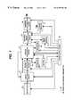
- FIG. 1is a functional block diagram of the electronic elements and circuits in one embodiment of the present invention
- FIG. 2 ais a functional block diagram showing the details of the speech recognition circuit in one embodiment of the present invention.
- FIG. 2 bis a functional block diagram showing the details of the infrared signal controlling circuit in one embodiment of the present invention.
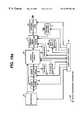
- FIG. 2 cis a schematic circuit diagram showing the details of the audio switching circuit and the sound activation circuit in one embodiment of the present invention
- FIG. 3is a perspective view of the physical housing for one embodiment of the present invention.
- FIG. 4 ais a side view of the housing illustrated in FIG. 3 .
- FIG. 4 bis an exploded perspective view of the housing illustrated in FIG. 3 .
- FIG. 4 cis a partial sectional view of the housing illustrated in FIG. 3 .
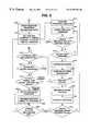
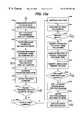
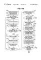
- FIG. 5is a functional block diagram showing the default operation modes of one embodiment of the present invention.
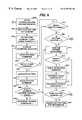
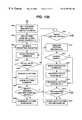
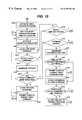
- FIG. 6is a functional block diagram showing the sound activation mode sequence steps for one embodiment of the present invention.
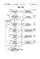
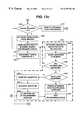
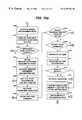
- FIG. 7is a functional block diagram showing the different recognition modes that may be utilized when different recognition vocabulary sets are activated in one embodiment of the present invention.
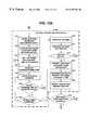
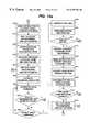
- FIG. 8is a functional block diagram showing the sequence of steps for the response prompting recognition mode for one embodiment of the present invention.
- FIG. 9is a functional block diagram showing the sequence of steps for the pattern queuing recognition mode for one embodiment of the present invention.
- FIG. 10is a functional block diagram showing a continuation of the sequence of steps for pattern queuing recognition mode for one embodiment of the present invention shown in FIG. 9;
- FIG. 11is a functional block diagram showing the sequence steps for executing a macro program in one embodiment of the present invention.
- FIGS. 12A and 12Bis a functional block diagram showing the sequence steps for initiating the product setup process for one embodiment of the present invention
- FIGS. 13A-13Cis a functional block diagram showing the sequence steps for selecting a controlled appliance code during a product setup process for one embodiment of the present invention
- FIGS. 14A and 14Bis a functional block diagram showing the sequence steps for learning an infrared signal from another remote control transmitter during a product setup process for one embodiment of the present invention
- FIG. 15is a functional block diagram showing the sequence steps for teaching custom, speaker dependent voice command names during a product setup process for one embodiment of the present invention
- FIGS. 16A and 16Bis a functional block diagram showing the sequence steps for creating a macro program during a product setup process for one embodiment of the present invention
- FIG. 17is a schematic circuit diagram showing the details of the power supply circuit of one embodiment of the present invention.
- FIG. 18 ais a functional block diagram of an alternative embodiment of an audio switching circuit in accordance with one embodiment of the present invention.
- FIG. 18 bis a functional block diagram of an alternate embodiment utilizing separate microphones for the sound activation circuit and speech recognition circuit in accordance with the present invention
- FIG. 18 cis a functional block diagram of another alternate embodiment utilizing separate microphones for the sound activation circuit and speech recognition circuit in accordance with the present invention.
- the present inventionrelates to a truly hands-free universal control unit system for controlling various appliances, such as entertainment appliances, for example, TVs, VCRs, stereo's and the like and may also be used for non-entertainment appliances and virtually any device that is amenable to remote control
- the universal remote control system in accordance with the present inventionis user programmable to enable any number of appliances to be programmed by the user.
- the universal control system in accordance with one embodiment of the inventionmay be battery operated. During periods when no voice commands are being issued the system enters a sleep or sound activation mode.
- An important aspect of the inventionrelates to the ability of the system to switch from a sleep mode to an active mode solely by voice commands, to provide true hands-free remote operation.
- FIG. 1A block diagram of the system in accordance with the present invention is illustrated in FIG. 1 and generally identified with the reference numeral 10 .
- the system 10enables hands-free operation of one or more appliances in a wireless manner.
- the system 10includes a microphone 20 , an audio switching circuit 30 , a sound activation circuit 40 , a speech recognition circuit 50 , and a transmitter, for example, an infrared signal controlling circuit 70 and one or more infrared light-emitting diodes 80 .
- the system 10may also contain an infrared receiver 71 , a read/write memory device 72 for storage of received IR signal data one or more indicators 52 , a keypad 51 and a speaker 53 .
- a power supply circuit 90is also included. The power supply 90 may be configured for DC operation to enable portability of the system 10 or alternatively AC operation.
- An output signal from the microphone 20is electrically connected to an automatic audio switching circuit 30 .
- the microphone 20may be one or more directional microphones, which have higher sensitivity to sound generated in predetermined regions in relation to the microphone's position than in other predetermined regions.
- a suitable microphoneis a model number M118HC directional microphone, available from Lucent Technologies and described in detail in; “DM 1000 Component Directional Microphone”, pages 1 and 2, available from Lucent Technologies, hereby incorporated by reference.
- Sound arriving at the microphoneis converted into an electric audio output signal by the microphone 20 and is directed to the audio switching circuit 30 .
- the microphone audio signal outputis directed to the speech recognition circuit 50 if the speech recognition circuit 50 is not in a sound activation mode. Conversely, if the speech recognition circuit 50 is in sound activation mode, the audio switching circuit 30 routes the microphone audio signal output to a sound activation circuit 40 .
- the output signal of the microphone 20is electrically connected to the sound activation circuit 40 which includes an amplification circuit (shown in detail in FIG. 2 c ), that amplifies the signal and a trigger circuit 43 (shown in FIG. 2 c ) that receives the amplified signal from the output of the amplification circuit.
- An output of the trigger circuit 43is electrically connected to an input/output pin of the speech recognition circuit 50 . If the amplified signal is of sufficient amplitude to activate the trigger circuit 43 , the output of the trigger circuit causes a logic state change on the input/output pin of the speech recognition circuit 50 , causing the invention to change modes from a sleep or sound activation mode to an awake or speech recognition mode.
- the mode changemay be done in software and/or hardware to cause the logic state of a mode output pin 65 (shown in FIG. 2 a ) of the speech recognition circuit 50 , connected to an input control of the audio switching circuit, to cause the audio switching circuit 30 to route the microphone output signal to the speech recognition circuit 50 .
- voice commandsmay then be received and recognized by the speech recognition circuit 50 .
- the speech recognition circuit 50may include output pins that are electrically connected to a infrared signal controlling circuit 70 . Upon recognition of a voice command associated with an instruction to the transmitter, for example, an infrared signal controlling circuit 70 , the speech recognition circuit 50 sends one or more signals using the output pins to the infrared signal controlling circuit 70 .
- the system 10 as illustrated and described hereintranslates the voice commands to infrared signals for controlling the appliance by way of an infrared link.
- the output from the speech recognition circuit 50is directed to a wireless transmitter, formed from an infrared signal controlling unit 70 and one or more infrared light emitting diodes 80 capable of transmitting infrared light in one or more wavelengths.
- the present inventionutilizes conventional infrared remote control microcontroller-based technologies, including the conventional universal appliance code libraries that are familiar to those skilled in the art.
- the systemmay utilize other wireless links, other than infrared or in addition thereto, such as RF, ultrasonic and optical links.
- certain aspects of the inventionincluding the mode changing from a sleep to an awake mode are adapted to be used with appliances that are either wired and wirelessly coupled to the system.
- the appliancesmay be coupled to the system 10 over a power distribution network.
- the principles of the present inventionenable truly hands free control of the appliances.
- the infrared signal controlling circuit 70is electrically connected to one or more infrared light emitting diodes 80 .
- the infrared signal controlling circuit 70receives and interprets signals from the speech recognition circuit 50 and if the signals communicate instructions to transmit infrared signals to a controlled appliance, the infrared signal controlling circuit 70 identifies the appropriate remote control code and sends a remote control signal representing the code to the infrared light emitting diode(s) 80 , which transmits the signal to the controlled appliance.
- An infrared receiver 71 , a read/write memory 72 , and an indicator 52 dmay be electrically connected to the infrared signal controlling circuit 80 .
- the infrared receiver 72detects and receives the infrared remote control signals transmitted by other remote control transmitters in a learn mode.
- the infrared signal controlling circuit 70receives these signals as digital output from the infrared receiver 72 .
- the infrared signal controlling circuit 70decodes and stores the digital signals as codes in the read/write memory 72 for later transmission.
- the indicator 52 dmay be used to provide a visual indicator to the user during said infrared signal receiving and transmitting operations.
- a keypad 51 , indicators 52 a , 52 b and 52 c , and a speaker 53may be electrically connected to the speech recognition circuit 50 .
- the keypad 51 buttonsmay be utilized by the user to send signals to the input pins of the speech recognition circuit 50 during a product setup process and to provide a power switch for the invention.
- the indicators 52may be utilized to provide the user with visual status of the system during setup and operation.
- the speaker 53is driven by the speech recognition circuit 50 pulse width modulation output and is primarily used to provide synthesized speech prompts to the user during product setup processes.
- Speech recognition circuit 50monitors conditions with a sound activation time-out counter and an error recognition counter. Upon the attainment of predetermined conditions discussed below, the speech recognition circuit 50 software enters a low power consuming sleep or sound activation mode.
- a power supply circuit 90electrically connects a power source (not shown) to circuitry distributing electric power to the electronic elements of the present invention.
- the power sourcemay be either AC or DC or a combination thereof.
- commercially available alkaline batteries or rechargeable battery packsare suitable for a DC power supply.
- FIG. 17shows the power supply circuit 90 in greater detail than that shown in FIG. 1 .
- one of the buttons present on the keypad 51may be connected to a momentary switch, which, when depressed and held for a sufficient duration of time, establishes an electrical connection between a power source 91 and an input control pin of a digitally controlled CMOS single-pole, single-throw (SPST) analog switch 93 .
- SPSTdigitally controlled CMOS single-pole, single-throw
- An example of a commercially available SPST switch for such purposesis a model number ADG701, available from Analog Devices, Inc. and described in a data sheet entitled; CMOS Low Voltage 2 ⁇ SPST Switches , Rev a, pages 1-8 available from Analog Devices, Inc., hereby incorporated by reference.
- the input control pinresponds to this electrical connection with the power source 91 in a manner equivalent to receiving a logic high digital input, resulting in a closed electrical connection between switch 93 source and drain pins and allowing a connection to be established between the power source 91 and a power distribution plane 94 .
- the speech recognition circuit IC 55becomes electrically connected with the power source 91 as described above, the software stored within its ROM 61 executes a program to set a predetermined output pin 68 to a logic high state.
- the output pin 68is electrically connected to the input control pin of the switch 93 .
- the response of the speech recognition circuit IC 55 to receiving electric energy during a power up sequenceis to cause switch 93 to establish a closed electrical connection between its source and drain pins.
- This electrical connection within switch 93allows the power source 91 to be electrically connected to the power distribution plane 94 which distributes electric energy throughout the printed circuit board assembly 16 for use by components requiring electric energy for operation.
- the software contained within the ROM 61 of the speech recognition circuit 50may respond to the recognition of a speech command such as “Power” when the appropriate recognition vocabulary set is active and under the conditions described below by executing a command to change the logic state of said output pin 68 to a logic low condition.
- This logic lowis then received by the input control pin of switch 93 , which responds by creating an open connection between switch 93 source and drain pins, and thus disconnecting power distribution plane 94 from the power source 91 .
- the present inventionmay be powered down via voice command. If the power switch 93 is open as shown in FIG. 17, the circuit elements reliant on this connection to receive energy do not receive electric energy.
- a protection diode 2for example, a commercially available 1N4001, located in series with the power source 91 and other electrical connections to prevent damage to other printed circuit board assembly 16 components in the event batteries are inserted with incorrect polarity orientation.
- the IC 55contains as a minimum a preamplifier 56 , an analog to digital converter (A/D) 57 , a speech processing unit 58 , an automatic gain control (AGC) 59 , a microcontroller 60 , a read-only memory (ROM) 61 , a random access memory (RAM) 62 , a pulse width modulation (PWM) output 67 or a digital to analog converter (not shown), a mode output 65 pin, a clock 63 , an external memory interface 66 , and two general purpose input/output (I/O) ports 68 .
- APCautomatic gain control
- PWMpulse width modulation
- speaker dependent speech recognitionthen involves comparing an unknown pattern generated from a voice command spoken by the user to the speaker dependent reference patterns within a specified recognition vocabulary set. This comparison may involve distance measurements and calculations of the fit of the unknown pattern to each of the reference patterns to determine the closest matching reference pattern.
- the present inventionmay implement one or more generally known algorithms, including but not limited to pattern matching that compares an unknown pattern with reference patterns, neural networks, and/or hidden Markov models.
- One embodiment of the present inventionmakes both speaker independent and speaker dependent speech recognition available to the user by providing factory-programmed speaker independent commands that require no additional user voice training and providing speaker dependent command training capability to allow the user to create custom names for appliances, functions, and macro programs.
- Speaker independent speech recognitionis designed to recognize words spoken by a plurality of users and is language dependent.
- Speaker independent command reference dataare generally derived from recordings of the specified spoken commands from several hundred individuals with different speech characteristics and accents in conditions similar to the environment of a product's intended use. Therefore, speaker independent commands require no voice training from the user.
- Speaker dependent recognitiongenerally involves a user training a product to recognize specific words, and is therefore not language dependent.
- the implementation of linked recognition sets as previously describedalso allows the user to easily access and navigate among both speaker dependent and speaker independent recognition vocabulary sets.
- Other embodiments of the present inventionmay be of the form of a speaker independent only version or a speaker dependent version where a user may follow a set-up sequence to train speaker dependent words in place of the speaker independent structure of the embodiment described here
- the audio switching circuit 30provides an electric connection between the microphone audio signal output and the preamplifier 56 in the speech recognition circuit 50 .
- the preamplifier 56provides signal amplification to a level suitable for analog to digital conversion.
- the analog to digital converter (A/D) 57preferably having an accuracy of at least 12 bits, is coupled to the output of the preamplifier 56 and converts the incoming audio waveform into digital representations of the incoming signal.
- the digital output of the analog to digital converter 57is directed to the speech processing unit 58 .
- the speech processing unit 58is controlled by the controller 60 and utilizes RAM 62 for temporary storage of data, control information and result registers, and an arithmetic logic unit (not shown) to produce band-pass-filtered representations of the input waveform in several frequency bands.
- the output of the speech processing unit 58is received by the controller 60 .
- the controller 60Utilizing code stored in ROM 61 as discussed below, and register space and data space provided by the RAM 62 , the controller 60 analyzes the filtered input waveforms to produce a pattern in real time that contains the significant acoustic information in the input signal.
- the controller 60executes recognition algorithm software to determine which voice command in the active recognition vocabulary set is the best match and was most likely spoken by the user.
- the controller 60utilizing control code stored in the ROM 61 , determines the appropriate operation of the system associated with the recognition result, such as generating appropriate outputs at general purpose input/output ports 68 .
- An automatic gain control (ACG) 59is controlled by the controller 60 and provides feedback to the preamplifier 56 for adjustment of the level of amplification performed on the microphone audio signal output due to variations in the input signal.
- the controller 60utilizes register space in the RAM 62 to control the logic states of predetermined control register bits to determine if the clock 63 is enabled or disabled and if the controller 60 is in a low power consuming mode or not.
- the controller 60may place the speech recognition circuit 50 into a low power consuming sound activation mode by changing the logic states of said control register bits, removing the clock source 64 from the oscillator 63 of IC 55 .
- the controller 60 softwarealso changes the logic state of a mode output 65 pin of the speech recognition circuit 50 , as it enters the sound activation mode.
- An input control for the audio switching circuit 30is electrically connected to said mode output 65 pin which changes logic states as the speech recognition circuit changes modes between speech recognition mode and sound activation mode.
- the input control for the audio switching circuit 30changes as the logic state of the mode output pin changes, causing the electric signal output from the microphone 20 to be electrically connected to the sound activation circuit 40 .
- the audio switching circuit connectionsare shown in detail in FIG. 2 c.
- Stopping and restarting the speech recognition circuit 50 as previously describeddoes not cause a reset of the controller 60 , nor cause loss of contents of internal registers and thus allows the input/outputs 68 to remain where last set.
- the power requirement for the speech recognition circuitis significantly reduced, but the ability to maintain its energy supply allows the speech recognition circuit to retain the contents of its internal register and previously set input/output 68 conditions and resume operation in a relatively uninterrupted manner.
- the energized speech recognition circuitremains capable of detecting input events at the IC 55 input 68 pins even when placed in low power consuming sound activation mode, further supporting the hands-free activation capability of the sound activated circuit 40 .
- the present inventionmay also contain software code stored in the ROM 61 to provide a user with a means of navigating a vocabulary structure consisting of multiple, partitioned recognition vocabulary sets. At any one time, no more than a single recognition vocabulary set is made active by the speech recognition circuit. With the total recognition vocabulary partitioned into smaller recognition vocabulary sets, improvements in recognition time and accuracy result because, in general, as a recognition vocabulary increases in size, recognition time increases and accuracy decreases.
- Recognition vocabulary setsare generally created such that the voice commands, represented by the reference data within each said set, have either functional similarities or otherwise share a relationship that is intuitive to the operator. A voice command in one recognition vocabulary set may activate another recognition vocabulary set.
- a usermay verbally navigate among different types of function selections and target appliance selections in an intuitive fashion, while limiting the number of alternative words among which the speech recognition circuit must discriminate during any given recognition process. Furthermore, since a pattern generated by a voice command is compared only to the words in the active recognition vocabulary set, the use of phonetically similar words is possible if such similar words are placed in different recognition vocabulary sets.
- the present inventionmonitors conditions with a time-out counter and an error counter to automatically return to a general default mode if certain conditions are met. In other words, when no match is found or a period elapses in which no recognition attempts occur, the system returns to a known default state.
- the present inventionmay be provided with a user selectable default recognition vocabulary set, which is appropriate for an intended appliance category, to which the software causes the controller 60 to return following the recognition of certain voice commands or as the result of other predetermined conditions such as the elapse of time-out periods or the detection of a specified number of speech recognition errors.
- Recognition vocabulary setscontain reference command data representing the group of voice commands the invention is expecting to receive at any time, i.e. when a particular recognition vocabulary set is active.
- the software running while a default recognition vocabulary set is available for speech recognitionmay typically be executing a routine where the speech recognition circuitry remains continuously available to generate patterns from detected voice commands unless otherwise processing a previous voice command for recognition or measuring the silence level to provide compensation for background noise.
- the controller 60executes the control code instruction(s) associated with the matching reference command.
- the control code instruction(s)may direct the controller 60 to activate a new recognition vocabulary set or utilize IC 55 output 68 pins to communicate instructions to the infrared signal controlling circuit 70 .
- Control code instructions directing the controller 60 to activate a new recognition vocabulary setmay also direct the controller 60 to enter a new operating mode utilizing different pattern generating and/or speech recognition software.
- FIG. 2 billustrates the infrared signal controlling circuit 70 in greater detail. More specifically, the infrared signal controlling circuit 70 includes a controller 76 , an interface 75 to the speech recognition circuit one or more clock sources 73 , and one or more infrared driver circuits 74 .
- the electronic elements of the controllerare in the form of an microcontroller integrated circuit, IC chip 76 as shown in FIG. 2 b .
- Such microcontroller-based ICs specifically designed for infrared remote control transmitter applications which support infrared signal learningare well described in the prior art and are commercially available.
- An example of a commercially available controller for such purposeis a model number Z86L98, available from Zilog, Inc.
- the controller IC 76generally contains, a controller, a read-only memory (ROM), a random access memory (RAM), a clock, an external memory interface, a timer, a modulator, one or more input ports, one or more output ports, and an encoder.
- a plurality of stored infrared instruction codes and a plurality of program instructionsare generally stored within a ROM memory.
- the RAMis used by controller IC 76 to store data for operations and control.
- the controller IC 76 oscillatorderives its source from clock source 73 such as a crystal or a ceramic resonator.
- the controller IC 76is electrically connected to an infrared receiver 71 that receives externally transmitted infrared function codes (from a teaching transmitter, not shown) and supplies them to controller IC 76 where they are conventionally decoded by the decoder, shown internally to controller IC 76 in FIG. 2 a .
- the external memory interfaceis used by the controller IC 76 to store and access learned infrared signal codes in the external read/write memory 72 .
- An infrared driverwhich is generally transistor-based, is electrically connected to controller IC 76 and electrically connected to infrared light-emitting diode 80 .
- An indicator light-emitting diode 52 dis also connected to controller IC 76 which provides the user message prompts and other information, such as indicating operating stages and prompting desired user actions, for assisting in the programming of the present invention.
- the universal library of appliance codesare generally stored within the ROM memory of the controller IC 76 are stored within a ROM memory external to controller IC 76 and accessible through an external memory interface. Codes acquired through infrared code learning are typically stored in a read/write memory external to controller IC 76 .
- the memory devicesare typically organized into a plurality of pages with the various infrared function codes for a particular appliance model being generally assigned to a specific memory page.
- an interface 75provides electrical connections between the speech recognition circuit 50 and the controller IC 76 .
- a plurality of output pins PO 0 , PO 1 , . . . PO r ⁇ 1 at the controller IC 76are electrically connected as data inputs to each of a series of multiplexers (MUX 0 , MUX 1 , . . . MUX n ⁇ 1 ) within the interface 75 , which in one embodiment may be a programmable logic device configured to operate a switching matrix, connecting controller IC 76 outputs to controller IC 76 inputs.
- a suitable programmable logic deviceis a MACH 4 CPLD logic device, available from Lattice Semiconductor Corporation and described in detail in Publication 17466, Rev j, May 1999, entitled; MACH 4 CPLD FAMILY Y High Performance EE CMOS Programmable Logic , by Lattice Semiconductor Corporation, hereby incorporated by reference.
- the output 68 pins of the speech recognition IC 55are electrically connected as select inputs SI 0 , SI 1 , . . . SI m ⁇ 1 to each of the multiplexers contained within the interface 75 .
- the output of each multiplexeris electrically connected exclusively to one input pin PI 0 , PI 1 , . . . PI n ⁇ 1 of controller IC 76 .
- the output 68 pinssend a binary instruction to the select pin inputs of the interface 75 multiplexers shown in FIG. 2 a .
- each multiplexermay select zero or one of the data inputs to be electrically connected to the multiplexer output.
- the interface 75further controls the output enable of each multiplexer such that the output is enabled only if one of the data inputs has been selected for that multiplexer. This process produces an input at controller IC 76 input pins that is equivalent to that resulting from a button depress on a keypad of a conventional remote control transmitter which generates circuit connections.
- the controller IC 76 softwareinterprets the instruction received at its input pin(s) and responds by (a) identifying a section of the ROM to be made available for subsequent access if the instruction is associated with an appliance category selection; (b) by identifying a memory location within its internal ROM and retrieving the control code stored therein if the instruction is associated with a command stored within the universal library of codes stored in ROM or (c) retrieving a learned infrared code stored in read/write memory 72 if the instruction is associated with a learned infrared signal.
- the controller 76utilizes its formatting program and its modulator to generate the precise carrier frequency, pulse width, pulse modulation, and overall timing format for a signal based upon the control code retrieved, and submits the signal to an infrared driver 74 which drives one or more infrared light emitting diodes 80 .
- the infrared light emitting diode 80converts the electrical signal received into an infrared signal which is transmitted to one or more target appliances.
- FIG. 2 cillustrates the audio switching circuit 30 and the sound activation circuit 40 in greater detail.
- FIG. 2 cshows the present invention in the sound activation mode as indicated by the audio switching circuit 30 maintaining a switch closure and therefore electrical connection between the microphone 20 output and the sound activation circuit 40 .
- the audio switching circuit 30 in the preferred embodiment of the present inventioncontains a commercially available digitally controlled, single-pole, double-throw (SPDT) analog switch, for example, a model number ADG 719 (CMOS Switch) available from Analog Devices and described in a data sheet entitled; CMOS Low Voltage 4 ⁇ SPDT Switch ADG 719, Rev a, pages 1-8, available from Analog Devices, hereby incorporated by reference.
- SPDTdigitally controlled, single-pole, double-throw
- FIG. 18 awhich employs a commercially available digitally controlled (digitally enabled input control), single-pole, single-throw (SPST) analog switch, instead of the SPDT switch employed within the embodiment described above, within the audio switching circuit 30 .
- SPSTdigitally controlled
- FIG. 18 aan electrical connection is always maintained between the microphone 20 output and the speech recognition circuit 50 , but the switch is used to either electrically connect or disconnect the sound activation circuit 40 to the microphone 20 output depending on the state of the mode pin 65 of the speech recognition circuit 50 .
- the speech recognition circuit 50controls the mode pin 65 logic state as described in further detail below for the embodiment discussed above such that the sound activation circuit 40 is electrically connected to the microphone 20 output only when the invention is placed into sound activation mode.
- FIG. 18 bAnother alternate embodiment is shown in FIG. 18 b which employs two microphones 20 a and 20 b , the output of each is dedicated to the speech recognition circuit 50 or the sound activation circuit 40 , respectively.
- the microphone outputsremain exclusively electrically connected to the speech recognition circuit 50 or the sound activation circuit 40 .
- no switchis used, but an additional microphone is introduced, and the sound activation circuit 40 is allowed to harmlessly trigger during the speech recognition mode.
- FIG. 18 cis a combination of the two alternate schemes presented above.
- This schemeemploys two microphones 20 a and 20 b , the output of each is dedicated to the speech recognition circuit 50 or the sound activation circuit 40 , respectively.
- an electrical connectionis always maintained between the microphone 20 a output and the speech recognition circuit 50 , but an SPST switch as described above is used to either electrically connect or disconnect the sound activation circuit 40 to the microphone 20 b output depending on the state of the mode pin 65 of the speech recognition circuit 50 .
- the speech recognition circuit 50controls the mode pin 65 logic state in the same manner as described later in further detail for the preferred embodiment such that the sound activation circuit 40 is electrically connected to the microphone 20 output only when the invention is placed into sound activation mode.
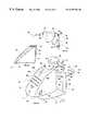
- FIGS. 3 and 4 a - 4 cillustrate an exemplary embodiment of a housing for the present invention.
- speech recognizing transmitter 10with a housing which includes a main housing portion 11 , a microphone base 12 which holds a microphone 20 and that may be rotated independently from said main enclosure section 11 , as described below and a removable battery access panel (not shown) on the bottom of the unit.
- Two ports 96 , 98 in the form of openingsare provided in the top of the microphone base 12 , through which sound is received by the microphone.
- An opening in the main enclosure section 11is provided for sound generated from a speaker 53 .
- the openingmay be formed from many small openings in the indicated area which may take the form of slits or cross-hatched pattern openings through which sound generated by the speaker 53 may pass through the main enclosure section 11 .
- the indicators 52 a , 52 b , 52 c and 52 dare light-emitting diodes operating in visible light wavelengths that are used to communicate operating status to the user. Openings may also be provided in the main enclosure 11 for each of said indicators.
- a keypad 51may be provided to enable the user access to buttons used primarily to communicate with the system during product setup processes. Openings are provided in the main enclosure 11 for each button of said keypad.
- a user-adjustable thumbwheel potentiometer 35may also be provided to allow the microphone sensitivity adjustment for electric audio signals directed to a speech recognition circuit.
- a user-adjustable thumbwheel potentiometer 45may be provided to allow adjustment of the amplification level of electric audio signals directed to a sound activation circuit. Openings may be provided in the main enclosure 11 for each of said thumbwheel potentiometers.
- vibration-absorbing, adhesive-backed feet 19made of rubber or similar compounds that are conducive to vibration absorption may be mounted to the bottom of main enclosure section 11 .
- An infrared receiver 71 or other wireless signal detecting devicemay be mounted within the rear portion of the main enclosure section 11 with an opening through which infrared light is received and detected.
- FIG. 4 ais a side elevational view of the physical structure of one embodiment of the present invention.
- FIG. 4 ashows infrared light-emitting diode 80 and a battery holding compartment 18 . Openings are provided in the main enclosure section 11 for each of the indicators and for mating of the removable battery access panel 17 (FIG. 4 b ) to the main enclosure section 11 .
- Electronic componentsare either mounted upon or are electrically connected by wiring to a printed circuit board assembly 16 shown with hidden lines.
- FIGS. 4 b and 4 cshow the rotatable IR transmitter and rotatable microphone feature in more detail.
- the housing 11may be formed from a front housing portion 82 and rear housing portion 84 .
- the front and rear housing portions 82 and 84are formed within continuous edges 86 and 88 , respectively, to enable the front 82 and rear housing portion 84 to be joined together with a suitable adhesive, such as an epoxy, or by way of ultrasonic welding or otherwise formed to be coupled together.
- a suitable adhesivesuch as an epoxy
- Each of the front 82 and rear 84 housing portionsincludes a semi-circular opening 85 , 87 formed at the top of the housing 11 .
- Semicircular annular notches 95 and 97are formed adjacent to each of the semicircular openings 85 and 87 . As will be discussed in more detail below, these semicircular annular notches 95 and 97 are for receiving a microphone base 12 and enabling it to rotate.
- the microphone base 12for example, as discussed above, includes a outer rim portion 99 formed as a disk. The outer rim portion 99 is adapted to be received in a semi-circular annular notches 95 and 97 in order to enable the microphone base 12 to be rotatably mounted with respect to the housing 11 .
- Electrical conductors 21are used to connect the microphone 20 to the circuitry described above. In order to protect the electrical connection between the electrical conductors 21 and the microphone from being damaged as a result of rotation of the microphone base 12 , sufficient slack is provided in the conductors 21 .
- the microphone 20may be a directional microphone. As such, the microphone 20 is provided with a pair of sound ports 22 and 23 . Rectangular openings 96 98 are provided in the microphone base 12 to allow sound to reach the microphone ports 22 and 23 .
- a radially extending rib 100may be provided on the outer rim portion 99 .
- An axially extending rib 102may be formed in one of the semicircular annular notches 95 , 97 to form a stop.
- the axial rib 102is adapted to engage the radial rib 100 on the outer rim portion 99 of the microphone base 12 to limit rotation of the microphone base 12 .
- the infrared light emitting diode 80may be rotatably mounted relative to the rear housing portion 84 .
- an opening 104may be provided in the rear housing portion 84 .
- a pair of spaced apart plates 106 and 108may be formed adjacent to the opening 104 and configured to extend into the rear housing portion 84 as generally shown in FIG. 4 b .
- a pair of protuberances 110may be formed on the upper and lower plate 106 and 108 to form a pivot axis.
- the infrared light emitted diodes 80may be carried by an irregularly shaped housing 112 having a top side 114 and a bottom side 116 .
- the housing 112is open on one end and contains apertures 118 and 120 in the top 114 and bottom 116 sides.
- the apertures 118 and 120are configured to receive the protuberances 110 and the top 106 and bottom plates 108 disposed inward in the rear housing portion 84 to enable the housing portion 112 to rotate relative to the rear housing portion 84 .
- An extending protuberance 81enables a user to rotate the housing 112 to adjust the physical orientation of the light emitting diode 80 .
- the housing portion 112is adapted to carry the infrared light emitting diodes 80 .
- Electrical conductors 89are used to provide an electrical connection between the infrared light emitting diode 80 and the balance of the circuitry.
- the conductors 89are provided with sufficient slack to avoid effecting the electrical connections to the electrical conductors when the housing 112 is rotated.
- the systemmay be AC or DC.
- a battery access hatch 17may be provided on the bottom of the housing 11 .
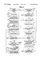
- FIG. 5is a flowchart form two default modes of the present invention.
- a sound activation modeis the default mode when the invention is operating in a low power consuming manner in a step S 501 . Otherwise, a continuous listening speech recognition mode is the default mode in a step S 505 unless a user is performing product setup processes.
- the speech recognition circuit 50remains electrically connected to the power supply circuitry 90 and receives electric power while in both of these modes. It should be noted that means is also provided to electrically disconnect the electric power source from the section of the power supply circuit that distributes electric power to other electronic elements within the present invention if it is desirable to prevent unintentional activation or if the invention is not to be used for an extended period of time.
- the command to disconnect power from said electronic elementsis not included within a default recognition vocabulary set to prevent unintentional deactivation of the invention and to prevent confusion with using the invention to power on and off controlled appliances.
- the commandis placed in a recognition vocabulary set that must be accessed by a command in another recognition vocabulary set to ensure recognition of said command is intentional.
- the inventionwill automatically return to the default speech recognition mode after the user has completed submitting voice commands within the recognition vocabulary set active at that time.
- the conditions under which other speech recognition routines cease and the default speech recognition mode becomes activeare described later.
- the microphone 20 , the audio switching circuit 30 , the sound activation circuit 40 and the speech recognition circuit IC 55While in the sound activation mode as shown in a step S 502 , the microphone 20 , the audio switching circuit 30 , the sound activation circuit 40 and the speech recognition circuit IC 55 , as a minimum, receive electric energy from the power supply circuit 90 .
- the microphone 20 , the audio switching circuit 30 , the sound activation circuit 40 and the speech recognition circuit IC 55as a minimum, have low power consuming characteristics while in the sound activation mode.
- the microphone 20converts the acoustic signal into an electric signal.
- the electric signal output from the microphone 20is electrically connected to either the sound activation circuit 40 if the system is in sound activation mode or the speech recognition circuit 50 if the system is in speech recognition mode.
- the audio switching circuit 30is set to one of these two possible states.
- an input control for the audio switching circuit 30is electrically connected to a speech recognition circuit 50 mode output 65 pin which changes logic states as the speech recognition circuit changes modes between sound activation mode and speech recognition mode.
- the input control for the audio switching circuit 30automatically detects the logic state of said mode output pin and changes the electrical connections for the electric signal output from the microphone 20 accordingly.
- the output signal from the microphone 20is electrically connected by the audio switching circuit 30 to the sound activation circuit 40 as shown in FIG. 2 c .
- the sound activation circuit 40contains one or more audio amplification stages that amplify the electric signal output from the microphone 20 .
- FIG. 2 cshows an audio signal amplification stage based upon an NPN transistor 41 a , followed by another audio signal amplification stage based upon an NPN transistor 41 b .
- the sound activation circuit 40also contains a trigger circuit.
- the trigger circuit shown in FIG. 2 cutilizes a series of three inverting Schmitt trigger circuits, shown collectively as IC 43 because IC are commercially available which integrate several such circuits into a single device package.
- the amplified output signal from the last audio amplification stageis electrically connected to an input of a first trigger circuit. If the resulting amplified electric audio signal representing the sound received by the microphone 20 reaches a predetermined amplitude threshold equal in magnitude to a logic state change (bit transition) at the input of the trigger circuit, the trigger circuit activates, indicating the sound has been detected as shown in a step S 502 .
- the first inverting trigger circuitthen outputs a logical low, leading to a logical high output at the second inverting trigger followed by a logical low output at the third inverting trigger in IC 43 . It is the output of the third inverting trigger that is electrically connected to the input pin 68 of the speech recognition circuit 50 .
- the general operation of such signal amplification and triggering circuitsare well know to those skilled in the electronics arts.
- the sound activation circuit 40also contains a potentiometer which allows resistance modification within the amplification circuit.
- This potentiometeris accessible to the user in the form of a thumbwheel knob 45 which the user can adjust to change a resistance value within the amplification circuit which modifies the sensitivity of the sound activation circuit.
- the logic state change of the output pin on the trigger circuitcauses a bit transition at the input 68 pin of the speech recognition circuit controller 60 .
- This bit transitionis detected by the controller 60 which responds by removing the speech recognition circuit from the low power consuming sound activation mode and enabling the controller clock 63 .
- Thisactivates the speech recognition circuit 50 for speech recognition processing as shown in a step S 503 .
- the softwarealso instructs the controller 60 to change the logic state of the mode output 65 pin.
- the speech recognition circuit 50then maintains the mode output 65 pin in the logic state consistent with the speech recognition mode. As indicated previously and shown in FIG. 2 c , an input control pin of the audio switching circuit 30 is electrically connected to said mode output 65 pin, causing the state of the audio switching circuit 30 to be controlled by said mode output pin.
- the logic state change at mode output 65 pinresults in a logic state change at the input control pin of the audio switching circuit 30 , causing said circuit to electrically connect the microphone 20 output signal to the speech recognition circuit 50 , disconnecting it from the sound activation circuit 40 , as shown in a step S 504 . This connection is maintained until the speech recognition circuit 50 determines that predetermined conditions have been met to return to the sound activation mode.
- the controller 60utilizes the ROM 61 to activate the speech recognition mode software as shown in a step S 505 .
- a sound activation mode time-out counter and a recognition error counterare set to zero as shown in a step S 506 .
- the sound activation time-out countertracks elapsed time between attempts made by the speech recognition circuit 50 to recognize sounds and if a predetermined time value TMAX elapses between recognition attempts, the speech recognition circuit software initiates a routine to enter sound activation mode and changes the logic states of the previously described control register bits.
- the recognition error countertracks the number attempts made by the speech recognition circuit 50 to recognize sounds for which no match is identified. The use of the recognition error counter is further described later. Each time a match is identified during speech recognition processing, the sound activation time-out counter value and the recognition error counter value are reset to zero value.
- a green light-emitting diode 52 ais activated and remains illuminated in a step S 507 while the speech recognition mode is available to execute a pattern generation algorithm to provide a visual indicator to the operator that the invention is ready to receive a voice command. It should be noted that this indicator will briefly deactivate during a silence level detection period, pattern generation or during speech recognition processing to inform the user that the speech recognition circuit 50 is temporarily unavailable to receive a voice command, but the green light-emitting diode 52 a re-illuminates after the silence level detection period is completed or recognition processing routine returns a result.
- the default speech recognition mode softwareexecutes a continuous listening routine.
- the green light-emitting diode 52 ailluminates while the speech recognition circuit is waiting to detect sounds for which to create patterns and submit for recognition processing as shown in step S 508 .
- the speech recognition circuitryexecutes a software routine that cycles among states where it monitors environmental sound level until a suitable silence level is detected, generates a pattern for a detected sound, compares the duration of the acquired pattern representing the detected sound to a defined duration for the active recognition vocabulary set commands, and when the duration of the detected sound pattern is consistent with said active recognition vocabulary set duration, executes a recognition algorithm to determine if a match can be identified for the acquired unknown pattern and one of the commands in the active recognition vocabulary set. Acquired patterns that are not consistent in duration with recognition vocabulary set commands (too long or too short) are ignored, and the speech recognition circuit software returns to execute the silence level detection routine.
- the silence level detection routinelistens (remains in a detection mode) until the noise level drops below a predetermined threshold, meaning a certain silence level is achieved. During this silence level detection routine, result codes are returned and compared to a noise threshold value until a result code is returned indicating the noise level has dropped below the predetermined threshold. Pattern generation can then be performed if a sound is detected. This cycle is shown as steps S 508 through S 517 .
- Such continuous listening software routinesare well known to those skilled in the art.
- the default mode speech recognition circuit softwarecycles between a silence level detection routine and a listening (ready for pattern generation) routine shown in steps S 508 , S 509 and S 510 while waiting for the detection of a sound.
- the sound activation time-out counter valueis periodically compared to the predetermined value TMAX in a step S 509 . If the time-out period elapses before a sound is detected, the speech recognition circuit 50 executes software code to enter the sound activation mode and disable the clock 63 from the clock source 64 as shown in FIG. 6 . If the time-out period has not elapsed, the speech recognition circuit 50 continues to cycle between a sound level detection routine and a listening (ready for pattern generation) routine, returning to steps S 508 , S 509 and S 510 .
- the green light-emitting diode 52 aceases to illuminate and a pattern is generated to represent the acoustically significant elements of the sound in a step S 511 .
- the duration of the acquired unknown pattern for the detected soundis compared to determine if its duration is consistent with the duration of the recognition vocabulary set commands in a step S 512 .
- the duration checkobviates the need to complete the speech recognition process if the pattern generated for the unknown sound, word, or phrase is either shorter or longer in duration than the commands in the active recognition vocabulary set, thus serving as a quick filter to allow the speech recognition circuit 50 to remain available for pattern generation for a increased proportion of the time.
- the value of the recognition error counteris incremented by one and the value of TMAX is reset to zero in a step S 515 and a red light-emitting diode 52 c illuminates briefly to provide a visual indicator to the operator in a step S 516 .
- the recognition error counter valueis then compared to a value EMAX, which is a predetermined value for the maximum number of recognition errors allowed, to determine if the two values are equal in a step S 517 . If the recognition error counter value is equal to value EMAX, the speech recognition circuit 50 executes software to enter the sound activation mode and disable the controller clock 63 from the clock source and shown in FIG. 6 .
- the recognition error counter valueis not equal to value EMAX, the green light-emitting diode 52 a is activated and remains illuminated and the speech recognition circuit 50 executes software which cycles between the silence level detection routine and the listening (ready for pattern generation) routine in steps S 508 , S 509 and S 510 .
- a pattern generated in a step S 511is found to be consistent in duration with the recognition vocabulary set command duration in a step S 512 , then the acquired unknown pattern is analyzed by the speech recognition circuit controller 60 , utilizing a recognition algorithm stored in its ROM 61 , to determined if it can be classified as a match with any of the reference commands within the active recognition vocabulary set and if the likelihood of correctly recognizing the unknown pattern exceeds a predetermined threshold in a step S 513 . The result of this comparison is identified in a step S 514 .
- the value of the recognition error counteris incremented by one and the value of TMAX is reset to zero in a step S 515 and the red light-emitting diode 52 c illuminates briefly to provide a visual indicator to the operator that no match was identified in a step S 516 .
- the recognition error counter valueis then compared to value EMAX in a step S 517 . If the recognition error counter value is equal to value EMAX, the speech recognition circuit 50 executes software stored in its ROM 61 to enter the sound activation mode and disable the clock 63 from the clock source 64 and as shown in FIG. 6 .
- the recognition error counter valueis not equal to value EMAX, the green light-emitting diode 52 a is activated and remains illuminated and the speech recognition circuit 50 executes software which cycles between the silence level detection routine and the listening (ready for pattern generation) routine in steps S 508 , S 509 and S 510 .
- the speech recognition circuit 50 softwareidentifies the operation associated with the matching recognition vocabulary set command in a step S 518 and determines if the operation is to send an instruction to the speech recognition circuit controller 60 to activate a new recognition set vocabulary or to output a signal to the infrared controlling circuit 70 using the speech recognition circuit input/output 68 pins.
- the signal to the infrared controlling circuitcommunicates either a appliance category selection command in a step S 520 or a command to transmit one or more infrared signals for specified functions to the currently controlled appliance in a step S 521 .
- the speech recognition circuit controller 60executes software stored in its ROM 61 to reset the values TMAX and EMAX to zero in a step S 506 , activates the green light-emitting diode 52 a in a step S 107 and returns to a continuous listening routine which cycles between the silence level detection routine and the listening (ready for pattern generation) routine in steps S 508 , S 509 and S 510 .
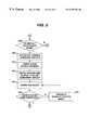
- FIG. 7shows the steps followed when the speech recognition circuit controller 60 receives a signal instructing it to activate a new recognition set.
- the present inventionuses conventional silence level detection, continuous listening, pattern generation, and speech recognition algorithms to perform the aforementioned software routines. These algorithms are well documented in the prior art and are familiar to those skilled in the electronics arts. For example, exemplary speech recognition algorithms are available from Sensory, Inc., Sunnyvale, Calif., under their brand name Sensory Speech 5.0 Technology. Other speech recognition algorithms which contain some of the features in the present invention include Voice DirectTM TSSP and Voice ActivationTM software, all available from Sensory, Inc. Other speech recognition algorithms are also suitable.
- the speech recognition circuit softwareperiodically monitors the status of two counter values that are independently controlled by the software. If either of these two values, the sound activation time-out counter value or the recognition error counter value, has reached its maximum allowed value TMAX or EMAX, respectively, the speech recognition circuit 50 changes the mode of the system from speech recognition mode to sound activation mode. Otherwise, as indicated in steps S 506 and S 515 shown in FIG. 5, these counters are also reset to zero.
- FIG. 6shows in a step S 620 the sound activation mode is entered only from a default recognition mode. If the active recognition vocabulary set is not a default recognition vocabulary set operating in a default recognition mode, then upon attainment of a maximum allowed counter value for a time-out counter or a recognition error counter, the software will return to a default recognition mode before the sound activation mode is entered as shown by a step S 620 in FIG. 6 referring to a step S 505 in FIG. 5 .
- a step S 621shows that when operating in a default recognition mode, and upon the attainment of the value TMAX for the sound activation time-out counter value or the value EMAX for the recognition error counter value, the speech recognition circuit 50 inactivates or disables the electronic elements that are not needed during sound activation mode such as indicators 52 a , 52 b , 52 c and 52 d to reduce power consumption during the sound activation mode.
- the systementers a sound activation mode as described previously by changing the states of control register bits that disable the clock oscillator 63 from its clock source 64 and place the speech recognition circuit in a low power consuming mode and setting the mode output 65 pin to the logic state defined for sound activation mode.
- an input control for the audio switching circuit 30is electrically connected to said mode output 65 pin which changes logic states as the speech recognition circuit changes modes between speech recognition mode and sound activation mode.
- the input control for the audio switching circuit 30detects the logic state of said mode output pin and electrically connects the electric signal output from the microphone 20 to the sound activation circuit 40 .
- the speech recognition circuitremains in this sound activation mode, listening for sound. While in the sound activation mode, the microphone 20 , the audio switching circuit 30 , the sound activation circuit 40 and the speech recognition circuit IC 55 , as a minimum, receive electric energy from the power supply circuit 90 .
- the microphone 20 , the audio switching circuit 30 , the sound activation circuit 40 and the speech recognition circuit IC 55as a minimum, have low power consuming characteristics at least while in the sound activation mode.
- the microphone 20converts the acoustic signal into an electric signal.
- the state of the audio switching circuit 30is set to electrically connect the electric signal output from the microphone 20 to the sound activation circuit 40 .
- the sound activation circuit 40contains one or more audio amplification stages, shown in FIG. 2 c , that amplify the electric signal output from the microphone 20 .
- the sound activation circuit 40also contains a trigger circuit 43 shown in FIG. 2 c .
- the amplified output signal from the last audio amplification stageis electrically connected to an input of the trigger circuit.
- the sound activation circuitactivates, indicating the sound has been detected at a step S 625 in FIG. 6 and referring to a step S 502 in FIG. 5 .
- the sound activation circuitis shown in detail in FIG. 2 c.
- a matchis identified during the pattern recognition process and the operation associated with the recognized command is an instruction to activate a different recognition vocabulary set
- the softwarewill execute the instruction to enter the appropriate recognition mode for the indicated recognition vocabulary set in a step S 628 shown in FIG. 7 .
- Recognition modesare commercially available that are capable of executing software that involves different recognition routines such as continuous listening, pattern queuing and response prompting recognition as described below.
- the continuous listening recognition modewas described previously in the explanation of FIG. 5 steps.
- a continuous listening routinemay also be executed for a non-default recognition vocabulary set. For brevity, an additional description of this mode is not provided. Instead, the system returns to step S 505 in FIG. 5, after which the same basic process follows. The primary exception being that when the maximum allowed time-out or recognition error counter value is attained, the speech recognition circuit 50 will not enter sound activation mode, but will instead enter the default continuous listening recognition mode as indicated in a step S 620 in FIG. 6 .
- a response prompting recognition modeis shown in FIG. 8 .
- the speech recognition circuit softwareactivates a recognition vocabulary set and executes a response prompting routine as shown in a step S 630 , the user is expected to select a voice command from the active recognition vocabulary set and respond when prompted by an illuminated green light emitting diode 52 b .
- a green light emitting diode 52 aremains illuminated in this mode when the speech recognition circuit 50 is available to generate patterns to indicate to the user that the active recognition mode is not the default recognition mode.
- a time-out counter and a recognition error counterare set to zero when the response prompting recognition mode is activated. However, the maximum allowed values for both of these counters are typically less than those for continuous listening recognition mode.
- the softwareFollowing the prompting of the user by the illumination of a green light emitting diode 52 b in a step S 632 , the software enters a pattern generating mode in a step S 633 , waiting for a voice command to be detected. If a maximum allowed time-out value TMAX 1 is attained before a voice command is detected, the software will terminate the response prompting routine and return to the default continuous listening recognition mode as shown in a step S 634 . Until time TMAX 1 has expired, the speech recognition circuit remains available to generate a pattern when a voice command is detected as shown in steps S 635 , S 633 and S 634 . If a voice command is detected in a step S 635 , a pattern is generated in a step S 636 and submitted for pattern recognition processing in a step S 637 .
- step 637the acquired unknown pattern is analyzed by the speech recognition circuit controller 60 , utilizing a recognition algorithm stored in its ROM 61 , to determined if it can be classified as a match with any of the reference commands within the active recognition vocabulary set and if the likelihood of correctly recognizing the unknown pattern exceeds a predetermined threshold. The result of this comparison is identified in a step S 638 .
- the value of the recognition error counteris incremented by one in a step S 638 and the red light-emitting diode 52 c illuminates briefly to provide a visual indicator to the operator that no match was identified in a step S 640 .
- the recognition error counter valueis then compared to a maximum allowed recognition error counter value EMAX 1 in a step S 641 . If the recognition error counter value is equal to value EMAX 1 , the speech recognition circuit 50 executes software stored in its ROM 61 to terminate the response prompting routine and return to a default continuous listening recognition mode as shown in a step S 641 and a step S 505 in FIG. 5 .
- the recognition error counter valueis not equal to value EMAX 1 , the green light-emitting diode 52 b is activated and remains illuminated and the speech recognition circuit 50 executes software to enter a pattern generating mode, returning to a step S 633 and waiting for a voice command to be detected. As previously indicated, until time TMAX 1 has expired, the speech recognition circuit remains available to generate a pattern when a voice command is detected as shown in steps S 635 , S 633 and S 634 .
- the speech recognition circuit 50 softwareidentifies the operation associated with the matching recognition vocabulary set command in a step S 642 and determines if the operation is to send an instruction to the speech recognition circuit controller 60 to activate a new recognition vocabulary set or not. If a new recognition vocabulary set is to be activated, the software executes the instruction to enter the appropriate recognition mode for the indicated recognition vocabulary set in a step S 628 shown in FIG. 7 .
- the operation associated with the recognized commandis to send an instruction to the speech recognition circuit controller 60 to activate a macro sequence of commands
- softwarebegins to execute the macro program as indicated in a step S 700 in FIG. 11, which is described later.
- a step S 644if the operation associated with the recognized command is to send an instruction to the speech recognition circuit controller 60 to output a signal to the infrared controlling circuit 70 , the software uses the speech recognition circuit input/output 68 pins.
- the signal to the infrared controlling circuitcommunicates either a appliance category selection command in a step S 645 or a command to transmit an infrared signal for a specified function to the currently controlled appliance in a step S 646 .
- the speech recognition circuit controller 60executes software stored in its ROM 61 to determine whether to remain in the active recognition vocabulary set to receive additional voice commands or to terminate the response prompting routine and return to a default continuous listening recognition mode as shown in a step S 647 and a step S 505 in FIG. 5 .
- the softwareIf remaining in the active recognition vocabulary set, the software resets the values TMAX 1 and EMAX 1 to zero in a step S 631 , activates the response prompting green light-emitting diode 52 b in a step S 632 and enters a pattern generating mode in a step S 633 , waiting for a voice command to be detected until either TMAX 1 or EMAX 1 counter values are attained, at which time the software will terminate the response prompting routine and return to a default continuous listening recognition mode as shown in steps S 634 or S 641 , followed by a step S 505 in FIG. 5 .
- pattern queuinginvolves the user providing a voice command after each prompt within a series of prompts. The number of prompts in the series is predetermined. A pattern is generated for each voice command as it is received, and the pattern is queued into memory. After patterns have been generated and queued into memory for all received voice commands, the voice commands are submitted one by one for recognition. Following recognition of each pattern, the operation instruction associated with the command in the active recognition vocabulary set identified as a match with the unknown pattern is queued into memory. When all patterns within the series have been recognized, and all associated operation instructions have been queued into memory, the controller 60 performs each of the operation instructions in a defined order.
- the systemutilizes a pattern queuing routine to allow a user to submit a string of consecutive voice commands, which may be separated by brief pauses, selected from a vocabulary recognition set which includes the names of digits zero through nine.
- a usersubmits the word “channel” during the continuous listening default routine.
- the softwareactivates said recognition vocabulary set including digit names and initiates a pattern queuing routine, prompting the user to submit one, two or three digit names to identify a desired channel number for an appliance.
- the speech recognition circuit softwareactivates a recognition vocabulary set and executes a pattern queuing routine as shown in a step S 660
- the useris expected to select a voice command from the active recognition vocabulary set and respond when prompted by an illuminated green light emitting diode 52 b .
- the green light emitting diode 52 aremains illuminated in this mode when the speech recognition circuit 50 is available to generate patterns to indicate to the user that the active recognition mode is not the default recognition mode.
- a time-out counteris set to zero when the pattern queuing recognition mode is activated as shown in a step S 661 .
- the maximum allowed value TMAX 2 for this counteris typically less than that for continuous listening recognition mode.
- a pattern counter and a queue counterare set to zero in a step S 662 .
- the pattern counter valueis incremented each time after a pattern is generated until a maximum pattern counter value MAXP is attained.
- each pattern counter number valueis representative of a single generated pattern and the maximum number attained by said counter is equal to the number of patterns generated.
- the value MAXPrepresents the maximum number of patterns the routine will generate before terminating the pattern generation process and beginning a speech recognition process.
- the minimum value for the pattern counter before the routine will generate speech recognition processingis one. If no patterns are generated within the time allowed, then the software returns to the default continuous listening mode.
- the queue counteris utilized in a similar manner to the pattern counter, except that it is used to track operation instructions identified during a speech recognition process. As a match is identified for an unknown pattern during the pattern recognition process, the operation instruction of the associated recognition vocabulary set command determined to be the best match is queued into memory until all generated patterns are processed through the speech recognition process. In this manner each queue counter number value is representative of an operation instruction now associated with a single generated pattern and is useful in retaining sequential order during the storage and retrieval of said instruction from memory. The maximum value attained by said queue counter is equal to the number of patterns generated. Unknown patterns for which no match is identified during the speech recognition process are ignored, in which cases the queue counter is not incremented.
- the speech recognition circuit 50 softwarebegins a listening routine (ready to generate a pattern) awaiting a voice command in a step S 664 .
- steps S 664 , S 665 and S 670the speech recognition circuit 50 system remains in this routine until either a voice command is detected in a step S 665 or the time-out counter value reaches the value TMAX 2 in step S 670 .
- a patternis generated by the speech recognition circuit 50 when a voice command is detected in a step S 665 .
- the generated unknown patternis queued into RAM 62 in a step S 667 .
- the value of the pattern counteris then compared with the value MAXP. If the pattern counter value is less than the value of MAXP, then the pattern counter value is incremented by one and the green light emitting diode 52 b provides a visual prompt in a step S 663 for the user to submit another voice command. This process continues to cycle through these steps S 663 through S 669 until either the pattern counter reaches the value MAXP in step S 668 , indicating the maximum number of patterns allowable have been generated, or until a time-out occurs as described previously. If a time-out does occur at a step S 670 , the value of the pattern counter is compared to the value zero in a step S 671 . If the pattern counter value is equal to zero, then the system returns to the default continuous listening mode as shown in a step S 505 in FIG. 5 . If the pattern counter value is not equal to zero, then patterns have been generated.
- Generated patternsare then submitted by the system for processing by the pattern recognition algorithm in a step S 672 , one pattern at a time, in reverse order from the pattern generation order.
- Suitable pattern recognition algorithmshave been described above.
- the speech recognition circuit 50 softwareidentifies the operation associated with the matching recognition vocabulary set command and queues this operation instruction into RAM 62 in a step S 674 .
- the queue counteris then incremented by the value one in a step S 675 .
- the pattern counteris then decremented by the value one in a step S 676 .
- the pattern counter valueis then compared to the value zero in a step S 677 to determine if there are any unknown patterns queued in RAM 62 which have not been submitted for speech recognition processing. If the pattern counter value is not equal to zero, then the software submits the next unknown pattern for speech recognition processing in a step S 678 and returns to step S 672 to perform pattern recognition.
- step S 678The software continues to cycle through steps S 672 through step S 678 until the pattern counter value is equal to value zero in step S 677 . If a match for an acquired pattern is not identified in a step S 673 , the pattern counter value is decremented by one in a step S 676 before proceeding to step S 677 .
- the softwarecompares the queue counter value to the value zero in a step S 680 in FIG. 10 to determine if there are any operation instructions queued in the RAM 62 . If the value of the queue counter is not equal to the value zero, the software retrieves from RAM 62 the operation instruction associated with the current value of the queue counter in a step S 681 .
- the speech recognition circuit 50executes the operation instruction in a step S 682 by sending a signal through the input/outputs 68 pins to the infrared signal controlling circuit 70 . The processing of said signal received by the infrared signal controlling circuit is described later.
- the speech recognition circuit 50 softwarethen decrements the queue counter value by the value one in a step S 683 and returns to step S 680 to determine if all operation instructions have been retrieved from RAM 62 .
- the softwarecontinues to cycle through steps S 680 through step S 683 until the queue counter value is equal to value zero in step S 680 at which time the system returns to the default continuous listening mode as shown in a step S 505 in FIG. 5 .
- the operation instruction associated with the recognized commandis processed by the speech recognition circuit controller 60 to determine an output signal to the infrared controlling circuit 70 , which is sent via the speech recognition circuit input/output 68 pins.
- the routine S 690identifies the processing steps performed within the infrared signal controlling circuit 70 .
- the signal from the speech recognition circuit output 68 pinsis received by inputs of the infrared signal controlling circuit 70 and processed to determine the associated remote control function in a step S 691 .
- the output from the speech recognition circuit output 68 pinsprovides a signal that is the informational equivalent to that of a signal generated when a button is depressed on a keypad of a conventional remote control transmitter.
- the input to the controller of the infrared signal controlling circuit 70can be uniquely associated with a function similarly to the input received from a conventional keypad generated circuit connection.
- the controller of the infrared signal controlling circuit 70interprets the signal received at its input pin(s) by identifying a memory location in a step S 692 and retrieving the control code stored therein. This controller generates a signal based upon the control code in a step S 693 and submits the signal to an infrared driver 74 , which drives one or more infrared light emitting diodes 80 in a step S 694 .
- the infrared light emitting diode 80converts the electrical signal into an infrared signal which is transmitted to one or more target appliances in a step S 695 .
- an interfaceis provided as part of the infrared signal controlling circuit 70 .
- the interfacesimulates the function of a switch matrix, connecting one or more inputs of the controller of the infrared signal controlling circuit 70 to one or more of its outputs as typically results when a keypad button is depressed.
- the speech recognition circuit 50sends a signal to this interface, the interface allows electrical connections to be established, similar to a keypad button depression, between inputs and outputs of the controller of the infrared signal controlling circuit 70 .
- One embodiment of the interfaceincludes a programmable logic device as discussed above and is shown in FIG. 2 b , described above. The interface provides an advantage since it is programmable and thus can be easily modified for use with a variety of controllers for infrared signal controlling circuits 70 .
- the recognition of a single voice commandmay generate a series of control signals to one or more target appliances.
- a sequence of control signalsis hereafter referred to as a macro.
- Each macromust be created by the user during a product setup process described below.
- Macrosmay contain operation instructions for appliance category selection, infrared signal codes and/or time delays. Macros are stored in the read/write memory 54 controlled by the speech recognition circuit 50 and may be associated with a user trained speaker dependent command.
- the speech recognition circuit 50 softwareretrieves the first instruction stored in the read/write 54 memory location associated with the recognized command. If the instruction retrieved is determined to be a time delay in a step S 701 , the software executes a time delay in a step S 702 and returns to step S 700 to retrieve the next instruction from memory. If the instruction is not a time delay, the speech recognition circuit 50 software sends a signal utilizing the speech recognition circuit input/output 68 pins to the infrared signal controlling circuit 70 in step S 703 .
- step S 704after a signal is sent to the infrared signal controlling circuit 70 , the software returns to the read/write 54 memory location associated with the recognized command to determine if another instruction is to be retrieved and processed. If so, the system retrieves the instruction, returning to step S 700 . The system continues to cycle through steps S 700 through step S 704 until an end marker is reached by the software in the memory location in a step S 704 , at which time the system returns to the default continuous listening mode as shown in step S 505 in FIG. 5 .
- the output from the speech recognition circuit input/output 68 pinsprovides sufficient information to the infrared signal controlling circuit 70 to generated a signal that is equivalent to that generated when a button is depressed on a keypad of a conventional remote control transmitter.
- the routine S 710identifies the processing steps performed within the infrared signal controlling circuit 70 .
- the signal from the speech recognition circuit input/output 68 pinsis received by inputs of the infrared signal controlling circuit 70 . If the signal contains an instruction to select an appliance category in a step S 711 , the infrared signal controlling circuit 70 responds in a step S 712 by making the memory locations associated with said appliance category active for subsequent access.
- the infrared signal controlling circuit 70performs these processes as indicated in steps S 713 through S 717 .
- the controller of the infrared signal controlling circuit 70interprets the signal received at its input pins in a step S 713 and identifies a memory location in a step S 714 , retrieving the control code stored therein.
- This controllergenerates a signal based upon the control code in a step S 715 and submits the signal to an infrared driver 74 , which drives an infrared light emitting diode 80 in a step S 716 .
- the infrared light emitting diode 80converts the electrical signal into an infrared signal which is transmitted to one or more target appliances in a step S 717 .
- one of the buttons present on keypad 51controls the state of a power switch
- the power switchIf the power switch is open as shown in a step S 202 , the power source is not electrically connected to sections of the power supply circuit 90 which have electrical connections to certain circuit elements and therefore, these circuit elements do not receive electric energy.
- the power sourceWhen this power switch is closed, the power source is electrically connected to sections of the power supply circuit 90 which have electrical connections to certain circuit elements and therefore, these circuit elements do receive electric energy.
- Step S 203shows that when the power supply button is momentarily depressed and the power switch is placed into a closed state, the speech recognition controller 60 executes a reset, sets a time-out counter to value zero and starts the time-out counter, which increments as time elapses.
- controller 60enters a waiting state where it monitors input 68 pins to determine if inputs are received from depressed buttons located on keypad 51 .
- step S 214the controller 60 executes code stored in ROM 61 to enter an appliance category selection routine shown in step S 220 in FIG. 12 b , which is described later.
- FIG. 13 a through FIG. 13 cshow the sequence of steps involved in programming such appliance codes.
- FIG. 14 a and FIG. 14 bshow the sequence of steps involved in learning infrared codes.
- FIG. 15shows the sequence of steps involved in user voice training for custom names.
- FIG. 16 a and FIG. 16 bshow the sequence of steps involved in creating macro programs.
- a reset as shown in step S 203may also be initiated when the invention is powered up and operating by depressing the setup button as shown in step S 204 .
- This resetfollows the same sequence as that resulting from an initial power up as shown in steps S 203 through in FIG. 12 a and FIG. 12 b.
- the controller 60executes code stored in ROM 61 to enter an appliance category selection routine shown in step S 220 in FIG. 12 b.
- a response prompting recognition mode for appliance category selectionis shown in FIG. 12 b .
- the speech recognition circuit 50 softwareexecutes a response prompting routine as shown in a step S 221 and activates the appliance category name recognition vocabulary set as shown in step S 222 .
- a time-out counteris set to zero and started in a step S 223 when the response prompting recognition mode is activated.
- the useris then expected to select a voice command from the appliance category name recognition set and respond when prompted by an illuminated green light emitting diode 52 a as shown in a step S 224 .
- the appliance category name recognition setmay be comprised of such voice command options as “television,” “video,” “satellite,” and “cable” among which the user may select.
- the systemFollowing the prompting of the user by the illumination of a green light emitting diode 52 a in a step S 224 , the system enters a pattern generating mode in a step S 225 , waiting for a voice command to be detected. If a maximum allowed time-out value TMAXD is attained before a voice command is detected, the software will terminate the response prompting routine and enter the default continuous listening recognition mode as shown in a step S 226 . Until time TMAXD has expired, the speech recognition circuit remains available to generate a pattern when a voice command is detected as shown in steps S 225 , S 226 and S 227 . If a voice command is detected in a step S 227 , a pattern is generated in a step S 228 and submitted for pattern recognition processing in a step S 229 .
- step S 229the acquired unknown pattern is analyzed by the speech recognition circuit controller 60 , utilizing a recognition algorithm stored in its ROM 61 , to determined if it can be classified as a match with any of the reference commands within the active recognition vocabulary set and if the likelihood of correctly recognizing the unknown pattern exceeds a predetermined threshold. The result of this comparison is identified in a step S 230 .
- the red light-emitting diode 52 cilluminates briefly to provide a visual indicator to the operator that no match was identified and the value of the recognition time-out counter is reset to the value zero and restarted as shown in a step S 223 .
- the green light-emitting diode 52 ais then activated and remains illuminated as shown in step S 224 and the speech recognition circuit 50 executes software to enter a pattern generating mode, returning to a step S 225 and waiting for a voice command to be detected.
- the speech recognition circuitremains available to generate a pattern when a voice command is detected as shown in steps S 225 , S 226 and S 227 .
- the speech recognition circuit 50 softwareidentifies the instruction associated with the matching recognition vocabulary set command, and issues a prompt, which may be a speech synthesis prompt, an audio sound or light-emitting diode indication, in a step S 231 to identify the appliance category name recognized.
- the speech recognition circuit 50then outputs a signal to the infrared controlling circuit 70 , using output 68 pins to communicate the appliance category selection command in a step S 232 .
- the infrared controlling circuit 70receives the signal and responds as shown in step S 233 by making the memory section associated with the appliance category selected available for access.
- step S 234the speech recognition circuit controller 60 executes software stored in its ROM 61 to return to a default continuous listening recognition mode as shown in a step S 234 and a step S 505 in FIG. 5 . If the appliance category name identified in step S 231 is incorrect, step S 234 also shows that the user may elect to press the setup button, returning to step S 204 in FIG. 12 a and begin the process again.
- step S 207 in FIG. 12 aIf the controller 60 detects an input corresponding to a depress of the code button shown in step S 207 in FIG. 12 a , a signal is sent to the infrared signal controlling circuit 70 , using output 68 pins to instruct the infrared signal controlling circuit to enter a programming mode.
- step S 240 in FIG. 13 athe controller of the infrared controlling circuit executes a programming routine from software stored within its ROM, which includes setting to value zero and starting a programming time-out counter in a step S 241 .
- the programming routineprepares the controller of the infrared signal controlling circuit 70 for subsequent receipt of a series of instructions.
- a first instructionidentifies the intended appliance category, which is then followed by a series of instructions, where each instruction represents an identifier digit of an appliance code.
- the appliance codeis comprised of a predetermined number of said identifier digits and uniquely identifies a specific control code set of the remote control command codes for a particular appliance.
- the controller of the infrared signal controlling circuit 70receives instructions identifying all the identifier digits of an appliance code, it is capable of identifying the memory location within the universal appliance code library stored within its ROM where the remote control command codes for the intended appliance type are stored. The control codes are then made available for subsequent signal transmission and resulting control of the intended appliance.
- universal remote controls employing such universal appliance code librariesare well documented in prior art.
- the controller of the infrared controlling circuit 70illuminates red light-emitting diode 52 d during the programming mode period.
- the speech recognizing circuit controller 60executes code stored in ROM 61 to enter a response prompting recognition mode for appliance category selection shown in step S 242 .
- the speech recognition circuit 50 softwareexecutes a response prompting routine and activates the appliance category name recognition vocabulary set as shown in step S 243 .
- a time-out counteris set to zero and started in a step S 244 when the response prompting recognition mode is activated.
- the useris then expected to select a voice command from the appliance category name recognition set and respond when prompted by an illuminated green light emitting diode 52 a as shown in a step S 245 .
- the appliance category name recognition setmay be comprised of such voice command options as “television,” “video,” “satellite,” and “cable” among which the user may select.
- the softwareenters a pattern generating mode in a step S 246 , waiting for a voice command to be detected. If a maximum allowed time-out value TMAXD is attained before a voice command is detected, the software will terminate the response prompting routine, and the programming time-out counter is allowed to expire as shown in step S 292 . Until time TMAXD has expired, the speech recognition circuit remains available to generate a pattern when a voice command is detected as shown in steps S 246 , S 247 and S 248 . If a voice command is detected in a step S 248 , a pattern is generated in a step S 249 and submitted for pattern recognition processing in a step S 250 .
- step S 250the acquired unknown pattern is analyzed by the speech recognition circuit controller 60 , utilizing a recognition algorithm stored in its ROM 61 , to determined if it can be classified as a match with any of the reference commands within the active recognition vocabulary set and if the likelihood of correctly recognizing the unknown pattern exceeds a predetermined threshold. The result of this comparison is identified in a step S 251 .
- the red light-emitting diode 52 cilluminates briefly to provide a visual indicator to the operator that no match was identified and the value of the recognition time-out counter is reset to the value zero and restarted as shown in a step S 244 .
- the green light-emitting diode 52 ais then activated and remains illuminated as shown in step S 245 and the speech recognition circuit 50 executes software to enter a pattern generating mode, returning to a step S 246 and waiting for a voice command to be detected.
- the speech recognition circuitremains available to generate a pattern when a voice command is detected as shown in steps S 246 , S 247 and S 248 .
- the speech recognition circuit 50 softwareidentifies the instruction associated with the matching recognition vocabulary set command, and issues a prompt, which may be a speech synthesis prompt, an audio sound or light-emitting diode indication, in a step S 252 to identify the appliance category name recognized.
- the speech recognition circuit 50then outputs a signal to the infrared controlling circuit 70 , using output 68 pins to communicate the appliance category selection command in a step S 253 .
- the infrared controlling circuit 70receives the signal and responds by making the memory section associated with the appliance category selected available for access in a step S 254 .
- the infrared controlling circuit 70then sets equal to value zero and restarts the programming time-out counter in a step S 256 .
- step S 257the speech recognition circuit controller 60 executes software stored in its ROM 61 to enter a pattern queuing recognition mode as shown in a step S 257 and to activate the digits recognition set as shown in step S 258 . If the appliance category name identified in step S 252 is incorrect, step S 255 shows that the programming time-out counter is allowed to expire as shown in step S 292 , before returning to step S 204 in FIG. 12 a and beginning the process again.
- the speech recognition circuit softwareexecutes a pattern queuing routine and activates the digit name recognition vocabulary set.
- the digit name recognition setmay be comprised of such voice command options as “zero,” “one,” “two,”. . . “nine” among which the user may select.
- a time-out counteris set to value zero and started when the pattern queuing recognition mode is activated as shown in a step S 260 in FIG. 13 b . Also at this time, a pattern counter and a queue counter are set to value zero in a step S 261 .
- the userselects an appliance code from a listing of the universal library of code supplied with the system and issues a spoken command identifying the first digit of the code when prompted by an illuminated green light emitting diode 52 b as shown in a step S 262 .
- the pattern counter valueis incremented each time after a pattern is generated until a maximum pattern counter value MAXC is attained.
- each pattern counter number valueis representative of a single generated pattern and the maximum number attained by said counter is equal to the number of patterns generated.
- the value MAXCrepresents the maximum number of patterns the routine will generate before terminating the pattern generation process and beginning a speech recognition process.
- the minimum value for the pattern counter before the routine will generate speech recognition processingis one. If no patterns are generated within the time allowed, then the software returns to the default continuous listening mode as described later.
- the queue counteris utilized in a similar manner to the pattern counter, except that it is used to track operation instructions identified during a speech recognition process. As a match is identified for an unknown pattern during the pattern recognition process, the operation instruction of the associated recognition vocabulary set command determined to be the best match is queued into memory until all generated patterns are processed through the speech recognition process. In this manner each queue counter number value is representative of an operation instruction now associated with a single generated pattern and is useful in retaining sequential order during the storage and retrieval of said instruction from memory. The maximum value attained by said queue counter is equal to the number of patterns generated. Unknown patterns for which no match is identified during the speech recognition process are ignored, in which cases the queue counter is not incremented.
- the speech recognition circuit 50 softwarebegins a listening routine (enters a state where it remains ready to generate a pattern) awaiting a voice command in a step S 263 .
- steps S 263 , S 264 and S 265the speech recognition circuit 50 software remains within said routine until either a voice command is detected in a step S 264 or the time-out counter value reaches the value TMAX 2 in step S 265 .
- a patternis generated by the speech recognition circuit 50 when a voice command is detected in a step S 264 .
- Said generated unknown patternis queued into RAM 62 in a step S 267 .
- the value of the pattern counteris then compared with the value MAXC. If the pattern counter value is less than the value of MAXC, then the pattern counter value is incremented by one in a step S 269 and the green light emitting diode 52 b provides a visual prompt in a step S 262 for the user to submit another voice command. This process continues to cycle through these steps S 262 through S 269 until either the pattern counter reaches the value MAXC in step S 268 , indicating the maximum number of patterns allowable have been generated, or until a time-out occurs as described previously. If a time-out does occur at a step S 265 , the user allows the programming time-out counter to expire as shown in step S 292 in FIG. 13 c , before returning to step S 204 in FIG. 12 a and beginning the process again or allowing the invention to automatically enter the default recognition mode.
- Generated patternsare then submitted by the software for processing by the pattern recognition algorithm in a step S 270 , one pattern at a time, in reverse order from the pattern generation order.
- the speech recognition circuit 50 softwareidentifies the operation associated with the matching recognition vocabulary set command and queues this operation instruction into RAM 62 in a step S 272 .
- the queue counteris then incremented by the value one in a step S 273 .
- the pattern counteris then decremented by the value one in a step S 274 .
- the pattern counter valueis then compared to the value zero in a step S 275 to determine if there are any unknown patterns queued in RAM 62 which have not been submitted for speech recognition processing. If the pattern counter value is not equal to zero, then the software submits the next unknown pattern for speech recognition processing in a step S 276 and returns to step S 270 to perform pattern recognition.
- step S 275The software continues to cycle through steps S 270 through step S 276 until the pattern counter value is equal to value zero in step S 275 . If a match for an acquired pattern is not identified in a step S 271 , the pattern counter value is decremented by one in a step S 274 before proceeding to step S 275 .
- the softwarecompares the queue counter value to the value zero in a step S 280 in FIG. 13 c to determine if there are any operation instructions queued in the RAM 62 . If the value of the queue counter is not equal to the value zero, the software retrieves from RAM 62 the operation instruction associated with the current value of the queue counter in a step S 282 .
- the speech recognition circuit 50executes said operation instruction in a step S 283 by sending a signal through the outputs 68 pins to the infrared signal controlling circuit 70 . The processing of said signal received by the infrared signal controlling circuit is described later.
- the speech recognition circuit 50 softwarethen decrements the queue counter value by the value one in a step S 284 and returns to step S 280 to determine if all operation instructions have been retrieved from RAM 62 .
- the softwarecontinues to cycle through steps S 280 through step S 284 until the queue counter value is equal to value zero in step S 280 at which time the software issues a prompt, which may be a speech synthesis prompt, an audio sound or light-emitting diode indication, in a step S 281 to identify the appliance code recognized, and then enters the default continuous listening mode as shown in a step S 505 in FIG. 5 .
- a promptwhich may be a speech synthesis prompt, an audio sound or light-emitting diode indication
- the operation instruction associated with the recognized commandis processed by the speech recognition circuit controller 60 to determine an output signal to the infrared controlling circuit 70 , which is sent via the speech recognition circuit output 68 pins.
- S 285identifies the processing steps performed within the infrared signal controlling circuit 70 .
- the signal from the speech recognition circuit output 68 pinsis received by inputs of the infrared signal controlling circuit 70 and processed to determine an identifier associated with a recognized digit name in a step S 286 .
- the output from the speech recognition circuit output 68 pinsis equivalent to a signal generated when a button is depressed on a keypad of a conventional remote control transmitter.
- the controller of the infrared signal controlling circuit 70stores the identifier associated with the signal received in a memory location in a step S 287 .
- Identifiersare determined and stored for each instruction received from the speech recognition circuit 50 until all instructions are received as determined in a step S 288 .
- the set of identifiersare then analyzed by the controller of the infrared controlling circuit 70 to determine if a they collectively comprise a valid appliance code in a step S 289 . If a valid code exists, the remote control functions associated with that code are assigned to the previously identified appliance category in a step S 293 and the programming mode is terminated in a step S 294 .
- step S 290If the code is not valid, the code is not accepted in a step S 290 and any previously established code remains active.
- Light-emitting diode 52 dilluminates in a step S 291 and the programming time-out counter is allowed to expire in a step S 292 .
- FIG. 13 calso shows that, as the programming time-out counter is allowed to expire, the time-out counter for the speech recognition circuit 50 is also allowed to expire, after which the speech recognition circuit 60 executes software stored in its ROM 61 to return to a default continuous listening recognition mode.
- the speech recognition circuit controller 60executes software stored in its ROM 61 to return to a default continuous listening recognition mode as shown in a steps S 281 in FIG. 13 c and a step S 505 in FIG. 5 . If the appliance category name identified in step S 281 is incorrect, the user may elect to press the setup button, returning to step S 204 in FIG. 12 a and begin the process again.
- step S 300 in FIG. 14 athe controller of the infrared controlling circuit executes a learning program routine from software stored within its ROM, which includes setting to value zero and starting a programming time-out counter in a step S 301 .
- the signal learning program routineprepares the controller of the infrared signal controlling circuit 70 for subsequent receipt of a series of instructions.
- a first instructionidentifies the intended appliance category, which is then followed by instructions to enter infrared signal learning mode.
- learning remote controlsare well documented in prior art, for example as disclosed in U.S. Pat. Nos. 4,905,279 and 5,959,751, hereby incorporated by reference.
- the controller of the infrared controlling circuitilluminates red light-emitting diode 52 d in different manners to communicate the status of the signal learning process to the user during this programming mode.
- the speech recognizing circuit controller 60executes code stored in ROM 61 to enter a response prompting recognition mode for appliance category selection shown in step S 302 .
- the speech recognition circuit 50 softwareexecutes a response prompting routine and activates the appliance category name recognition vocabulary set as shown in step S 303 .
- a time-out counteris set to zero and started in a step S 304 when the response prompting recognition mode is activated.
- the useris then expected to select a voice command from the appliance category name recognition set and respond when prompted by a speech synthesis prompt, an audio sound and/or the illumination of a green light emitting diode 52 a as shown in a step S 305 .
- the appliance category name recognition setmay be comprised of such voice command options as “television,” “video,” “satellite,” and “cable” among which the user may select.
- the softwareenters a pattern generating mode in a step S 306 , waiting for a voice command to be detected. If a maximum allowed time-out value TMAXD is attained before a voice command is detected, the software will terminate the response prompting routine and return to a default continuous listening recognition mode, and the programming time-out counter is allowed to expire as shown in step S 292 as shown in FIG. 13 c . Until time TMAXD has expired, the speech recognition circuit remains available to generate a pattern when a voice command is detected as shown in steps S 306 , S 307 and S 308 . If a voice command is detected in a step S 308 , a pattern is generated in a step S 309 and submitted for pattern recognition processing in a step S 310 .
- step S 310the acquired unknown pattern is analyzed by the speech recognition circuit controller 60 , utilizing a recognition algorithm stored in its ROM 61 , to determined if it can be classified as a match with any of the reference commands within the active recognition vocabulary set and if the likelihood of correctly recognizing the unknown pattern exceeds a predetermined threshold. The result of this comparison is identified in a step S 311 .
- the red light-emitting diode 52 cilluminates briefly to provide a visual indicator to the operator that no match was identified and the value of the recognition time-out counter is reset to the value zero and restarted as shown in a step S 304 .
- the green light-emitting diode 52 ais then activated and remains illuminated as shown in step S 305 and the speech recognition circuit 50 executes software to enter a pattern generating mode, returning to a step S 306 and waiting for a voice command to be detected.
- the speech recognition circuitremains available to generate a pattern when a voice command is detected as shown in steps S 306 , S 307 and S 308 .
- the speech recognition circuit 50 softwareidentifies the instruction associated with the matching recognition vocabulary set command, and issues a prompt, which may be a speech synthesis prompt, an audio sound or light-emitting diode indication, in a step S 312 to identify the appliance category name recognized.
- the speech recognition circuit 50then outputs a signal to the infrared controlling circuit 70 , using output 68 pins to communicate the appliance category selection command in a step S 313 .
- the infrared controlling circuit 70receives the signal and responds by making the memory section associated with the appliance category selected available for access in a step S 314 .
- the infrared controlling circuit 70then sets equal to value zero and restarts the programming time-out counter in a step S 317 .
- step S 316shows that the programming time-out counter is allowed to expire as shown in step S 292 shown in FIG. 13 c , before returning to step S 204 in FIG. 12 a and beginning the process again.
- 13 calso shows that, as the programming time-out counter is allowed to expire, the time-out counter for the speech recognition circuit 50 is also allowed to expire, by reaching the value TMAXD, after which the speech recognition circuit 60 executes software stored in its ROM 61 to return to a default continuous speech recognition mode.
- the speech recognition circuit controller 60executes software stored in its ROM 61 to enter a default recognition mode and to activate a default recognition vocabulary set as shown in a step S 320 in FIG. 14 b .
- This default recognition vocabulary setis made available to enable the user to navigate the recognition vocabulary structure via spoken commands to identify a command with which to associate the next infrared signal to be learned.
- a recognition time-out counteris set to zero and started in a step S 321 when the default recognition mode is activated.
- the useris then expected to select a voice command from the default recognition vocabulary set and respond when a green light emitting diode 52 a is illuminated as shown in a step S 322 .
- the default recognition vocabulary setmay be comprised of such voice command options as “power,” “channel,” “change,” “volume,” “sound,” “control” and “private” among which the user may select.
- the softwareenters a mode where it is available for pattern generating in a step S 323 , waiting for a voice command to be detected. If a maximum allowed time-out value TMAXL is attained before a voice command is detected, the software will terminate the speech recognition routine and return to a default continuous listening recognition mode, and the programming time-out counter is allowed to expire as shown in step S 292 shown in FIG. 12 c . Until time TMAXL has expired, the speech recognition circuit remains available to generate a pattern when a voice command is detected as shown in steps S 323 , S 324 and S 325 . If a voice command is detected in a step S 325 , a pattern is generated in a step S 326 .
- the acquired unknown patternis analyzed by the speech recognition circuit controller 60 , utilizing a recognition algorithm stored in its ROM 61 , to determined if it can be classified as a match with any of the reference commands within the default recognition vocabulary set and if the likelihood of correctly recognizing the unknown pattern exceeds a predetermined threshold.
- the result of this comparisonis identified in a step S 328 .
- the red light-emitting diode 52 cilluminates briefly to provide a visual indicator to the operator that no match was identified and the value of the recognition time-out counter is reset to the value zero and restarted as shown in a step S 321 .
- the green light-emitting diode 52 ais then activated and remains illuminated as shown in step S 322 and the speech recognition circuit 50 executes software to enter a pattern generating mode, returning to a step S 323 and waiting for a voice command to be detected.
- the speech recognition circuitremains available to generate a pattern when a voice command is detected as shown in steps S 323 , S 324 and S 325 .
- the speech recognition circuit 50 softwareidentifies the operation associated with the matching recognition vocabulary set command in a step S 329 and determines if the operation is to send an instruction to the speech recognition circuit controller 60 to activate a different recognition set vocabulary or to output a signal to the infrared controlling circuit 70 using the speech recognition circuit output 68 pins. If the instruction is to activate a different recognition vocabulary set, step S 330 shows that the routine returns to a step S 320 . The user may continue to navigate through different linked, recognition vocabulary sets until a voice command is recognized that is associated with a remote control function that is associated with a read/write memory 72 location.
- the operationinvolves sending a signal to the infrared signal controlling circuit as shown in a step S 331 , said signal communicates an instruction for a remote control function type that is associated with a memory location within read/write memory 72 , controlled by the infrared signal controlling circuit 70 .
- the controller of the infrared signal controlling circuit 70identifies said memory location and targets this memory location for storage of an infrared code to be received as shown in a step S 332 .
- the controller of the infrared signal controlling circuit 70activates a red light-emitting diode 52 d in a step S 333 to prompt a user that it is ready to receive a transmitted infrared code and enables one or more of its input pins to detect and receive signals generated by the infrared receiver 71 , which is electrically connected to one or more of said input pins.
- infrared receiver 71is a commercially available photo IC capable of providing digital output to the controller of the infrared signal controlling circuit 70 .
- Alternative schemes, utilizing other infrared light detecting devices with or without signal processing circuitry,may also be used as the IR receiver 71 .
- the infrared signalis received from the IR receiver 71 of the present invention by the controller of the infrared signal controlling circuit 70 as digital data.
- the controller of the infrared signal controlling circuit 70decodes and converts the received digital data into a control code format and stores the resulting control code into a memory location within read/write memory 72 , controlled by the infrared signal controlling circuit 70 .
- the memory locationis associated with the remote control function type associated with the recognized voice command spoken by the user.
- the controller of the infrared signal controlling circuit 70activates a red light-emitting diode 52 d in a step S 335 to inform the user if the infrared signal learning process was capable of successfully receiving, formatting and storing the infrared signal or not.
- This red light-emitting diode 52 dprovides prompts in different manners to distinguish between a successful learning process and a process during which an error was encountered.
- a successfully learned and stored infrared signalmay be later transmitted by the invention while in an operation mode upon recognition of the voice command with which the learned infrared signal is associated.
- the controller of the infrared signal controlling circuitexecutes software stored within its ROM to reset to value zero and start the programming time-out counter, returning to a step S 317 shown in FIG. 14 a .
- the speech recognition circuit controller 60executes software stored in its ROM 61 to return to the default recognition mode and reset the value TMAXL to zero as shown in steps S 331 and S 320 .
- a usermay elect to either return to the previous process steps to repeat a previously failing signal learning attempt or to attempt to learn additional infrared signals or the user may elect to allow the programming time-out counter of the infrared signal controlling circuit 70 to expire as shown in step S 292 shown in FIG. 12 c.
- the inventionexits this setup programming mode and enters a default recognition mode, where it becomes available to receive spoken commands from the user and respond by transmitting infrared control signals to appliances, including any infrared signals learned during a infrared signal learning setup process as described above.
- a speaker dependent command voice training routineis initiated and executed by said controller as shown in a step S 340 in FIG. 15 .
- This training routinegenerates and stores into read/write memory 54 a user-specific reference pattern for each voice command to be included in a speaker dependent recognition vocabulary set.
- the speech recognition circuit controller 60executes software stored in its ROM 61 to set to value zero and start a training program time-out counter as shown in a step S 341 .
- the softwareFollowing the prompting of the user by a speech synthesis prompt, an audio sound and/or the illumination of a green light emitting diode 52 a in a step S 342 , the software enters a mode where it is available for pattern generating in a step S 343 , waiting for a voice command to be detected. If a maximum allowed time-out value TMAXV is attained before a voice command is detected, the software will terminate the voice training as shown in step S 345 and enter a default speech recognition operation mode which is described previously. Until time TMAXV has expired, the speech recognition circuit remains available to generate a pattern when a voice command is detected as shown in steps S 343 , S 344 , S 345 and S 346 . If a voice command is detected in a step S 344 , a pattern is generated in a step S 346 .
- One embodiment of the inventionexecutes a speaker dependent reference pattern generation algorithm that is well known to those familiar with speech recognition art.
- the algorithminvolves the generation of a pattern each time a voice command is spoken by a user.
- a patternis a compact representation of the significant acoustic information in a voice command word or phrase.
- a reference patternmay be, for example, created by averaging patterns generated as the voice command is spoken two or more times.
- the reference patternis then stored in a read/write memory 54 .
- the first pattern generatedis stored into a read/write memory 54 location.
- the useris then prompted in a step S 349 to repeat the voice command, returning to step S 341 and continuing through step S 346 to perform the pattern generation process for the repeated voice command.
- the second patternis then compared to the first pattern which is stored in read/write memory 54 to determine if the two patterns match sufficiently to satisfy a predetermined matching criteria as shown in a step S 350 . If the matching criteria is not satisfied, the two patterns are determined to not match, and the first pattern generated is replaced by storing the second pattern generated into the previously identified read/write memory 54 location, and thus overwriting the first pattern.
- the useris then prompted in a step S 349 to repeat the voice command, returning to step S 341 and continuing through step S 346 to perform the pattern generation process for the repeated voice command. As shown by steps S 341 through S 350 this process cycle may be continued until two patterns are generated which are capable of meeting said matching criteria.
- a reference patternis generated as shown in step S 351 .
- a pattern recognition routineis then executed to compare the resulting reference pattern to any other previously generated reference patterns within the intended recognition vocabulary set which are stored in read/write memory 54 to determine if the new reference pattern is sufficiently different than said previously generated reference patterns. This comparison is performed to prevent the acceptance of similar voice commands, which may reduce the recognition accuracy rate.
- the comparisonmay calculate distance measurements of the fit of the newly generated reference pattern to the previously generated reference patterns within the intended recognition vocabulary set. The distance measurements between the newly generated reference pattern and the closest matching previously generated reference pattern(s) may then be compared to a predetermined comparison criteria to determine the degree of similarity. If the newly generated reference pattern is too similar to an existing reference pattern, the newly generated reference pattern is rejected, and the user is prompted in a step S 353 to select a different voice command name, returning to step S 341 .
- the speech recognition circuit controller 60executes software stored in its ROM 61 to determine if sufficient capacity remains in read/write memory 54 to allow additional voice commands to be trained. If there is sufficient capacity in the memory 54 , the system returns to step S 341 , where the user is prompted to enter another voice command by a speech synthesis prompt, an audio sound and/or the illumination of a green light emitting diode 52 a . If the user desires to exit this voice training mode, the user allows the training program time-out counter to expire as shown in a step S 356 . If there is insufficient capacity in the memory 54 , the user is informed accordingly by a speech synthesis prompt, an audio sound and/or the illumination of a red light emitting diode 52 c and the training program terminates.
- the contents of the read/write memory 54may be erased by depressing and simultaneously holding the name command button and the code button for a brief period of time.
- Depressing and momentarily holding two predetermined buttons on keypad 51may cause the address pointer for the read/write memory 54 to be set to zero, allowing any data previously stored within said memory to be overwritten during subsequent write operations to said memory. This enables a user to effectively “erase” this memory and store different data in a form of speech command reference pattern data and macro program instruction data.
- the read/write memory 54 utilized in the preferred embodiment of the present inventionmay be a commercially available I 2 CTM Serial EEPROM, for example a model number 24LC64 available from MicroChip Technology Inc. and described in a data sheet entitled; 24 AA 64/24 LC 64 64 K I 2 CTM MOS Serial EEPROM , document number DS21189C published by MicroChip Technology Inc. copyright 1999, pages 1-12, available from MicroChip Technology Inc., hereby incorporated by reference.
- I 2 CTM Serial EEPROMfor example a model number 24LC64 available from MicroChip Technology Inc. and described in a data sheet entitled; 24 AA 64/24 LC 64 64 K I 2 CTM MOS Serial EEPROM , document number DS21189C published by MicroChip Technology Inc. copyright 1999, pages 1-12, available from MicroChip Technology Inc., hereby incorporated by reference.
- the software stored in ROM 61 of the speech recognition circuit 50executes a program which detects this condition and responds by setting the address pointer for the next available address location for memory 54 to value zero and storing this value in the predetermined address pointer location of said memory 54 .
- the next attempt by the speech recognition circuit software to store data to said memory 54will retrieve the value of the address pointer for the next available location from said predetermined location within memory 54 , and interpret the value zero as an instruction to begin storing data in the first address configured to accept data.
- step S 360the system executes an appliance category selection routine as described in step S 220 in FIG. 12 b to identify the appliance category from which the macro will be activated when the macro name is later recognized by the speech recognition circuit 50 as a voice command. If the appliance category name identified during the execution of the appliance category selection routine is incorrect, step S 362 shows that the user may elect to press the setup button, returning to step S 204 in FIG. 12 a and begin the process again.
- a step S 362shows that the software enters a speaker dependent recognition mode in a step S 363 and a speaker dependent recognition vocabulary set is activated in a step S 364 .
- the speaker dependent recognition vocabulary set activatedmay contain one or more macro names, and possibly other speaker dependent voice commands for non-macro uses, previously trained by the user in accordance with the process steps described in FIG. 15 .
- the speech recognition circuit controller 60executes software stored in its ROM 61 to set to value zero and start a recognition time-out counter as shown in a step S 365 .
- the softwareFollowing the prompting of the user by a speech synthesis prompt, an audio sound and/or the illumination of a green light emitting diode 52 a in a step S 366 , the software enters a mode where it is available for pattern generating in a step S 367 , waiting for a voice command to be detected. If a maximum allowed time-out value TMAXM is attained before a voice command is detected, the software will terminate the macro programming routine as shown in step S 368 and the user may elect to press the setup button, returning to step S 204 in FIG. 12 a and begin the process again.
- step S 371the acquired unknown pattern is analyzed by the speech recognition circuit controller 60 , utilizing a recognition algorithm stored in its ROM 61 , to determined if it can be classified as a match with any of the reference commands within the active recognition vocabulary set and if the likelihood of correctly recognizing the unknown pattern exceeds a predetermined threshold. The result of this comparison is identified in a step S 372 .
- a red light-emitting diode 52 cilluminates briefly to provide a visual indicator to the operator that no match was identified in a step S 373 and returns to step S 365 to set to value zero and start a recognition time-out counter.
- the softwarethen re-enters a mode where it is available for pattern generating, waiting for a voice command to be detected. As previously indicated, until time TMAXM has expired, the speech recognition circuit remains available to generate a pattern when a voice command is detected as shown in steps S 367 , S 368 and S 369 .
- the speech recognition circuit 50 softwareidentifies a read/write memory 54 location associated with the matching recognition vocabulary set command in a step S 374 .
- Said memory 54 locationis used to store the sequence of commands instructions to be associated with the macro name identified by the preceding voice command.
- the software executed by the speech recognition circuit controller 60then activates the default recognition mode associated with the appliance device type previously selected.
- the speech recognition circuit controller 60executes software stored in its ROM 61 to enter a default recognition mode and to activate a default recognition vocabulary set as shown in a step S 381 in FIG. 16 b .
- This default recognition vocabulary setis made available to enable the user to navigate the recognition vocabulary structure via spoken commands to identify a voice command for which the associated instruction is to be stored within the read/write memory 54 location associated with said macro name voice command.
- a recognition time-out counteris set to zero and started in a step S 382 when a recognition mode is activated.
- the useris then expected to select a voice command from the default recognition vocabulary set and respond when prompted by a speech synthesis prompt, an audio sound and/or the illumination of a green light emitting diode 52 a as shown in a step S 383 .
- the default recognition vocabulary setmay be comprised of such voice command options as “power,” “channel,” “change,” “volume,” “sound,” “control” and “private” among which the user may select.
- the acquired unknown patternis analyzed by the speech recognition circuit controller 60 , utilizing a recognition algorithm stored in its ROM 61 , to determined if it can be classified as a match with any of the reference commands within the active recognition vocabulary set and if the likelihood of correctly recognizing the unknown pattern exceeds a predetermined threshold. The result of this comparison is identified in a step S 389 .
- the red light-emitting diode 52 cilluminates briefly to provide a visual indicator to the operator that no match was identified as shown in a step S 390 and the value of the recognition time-out counter is reset to the value zero and restarted as shown in a step S 382 .
- the green light-emitting diode 52 ais then activated and remains illuminated as shown in step S 383 and the speech recognition circuit 50 executes software to enter a pattern generating mode, returning to a step S 384 and waiting for a voice command to be detected.
- the speech recognition circuitremains in the active recognition mode available to generate a pattern when a voice command is detected as shown in steps S 384 , S 385 and S 386 .
- a voice commandis recognized that is associated with an instruction to output a signal to the infrared controlling circuit 70 , the associated instruction is stored within the read/write memory 54 location associated with said macro name voice command as shown in a step S 392 .
- an end marker instructionmay be automatically stored by the speech recognition circuit 50 software as shown in step S 393 . The user must then determine if this is the last instruction to be added to the macro program or not. If another instruction is to be added, the user must determine if it is desirable to insert a time delay between the execution of the currently identified instruction and a following macro instruction to be selected.
- a keypad 51 designated as a time delay buttonone or more times, where each button depress increases the length of the time delay by a brief period (typically 0.5 seconds or less) by storing one or a series of time delay instructions within the read/write memory 54 location associated with said macro name voice command as shown in a step S 395 .
- the time delay instructionsare stored into said memory 54 location in a section sequentially following the section of the instruction previously identified via voice command.
- the userdetermines that another instruction is be added to the macro program, then the user depresses the macro button as shown in a step S 396 , the software returns to a step S 375 shown in FIG. 16 a , and the software executed by the speech recognition circuit controller 60 then activates the default recognition mode associated with the appliance device type previously selected. As indicated previously, this default recognition vocabulary set is made available to enable the user to navigate the recognition vocabulary structure via spoken commands to identify another voice command for which the associated instruction is also to be stored within the read/write memory 54 location associated with said macro name voice command.
- Each additional instruction added to a macrois stored in the same memory 54 location as that of the previously stored end marker instruction, which was stored by the software after the previous macro instruction was stored, thus over-writing the end markers.
- This process for adding instructions to said memory location 54 associated with said macrocontinues until the user determines the last instruction has been identified via voice command.
- the userdepresses a keypad 51 button designated as a program completion button as shown in a step S 397 to instruct the speech recognition circuit controller 60 to execute software stored in its ROM 61 terminate the macro programming routine and enter the default recognition mode associated with the previously identified appliance category as shown in step S 398 .
- buttons other than the macro buttonsuch as the code button and signal learning button, may be used for such functions as time delay insertion and end marker insertion into the macro sequence.
- This approachallows for a reduction of the required button count, and is particularly useful for such relatively infrequently used functions as those identified above.
- FIG. 17shows the power supply circuit 90 in greater detail than that shown in FIG. 1 . This circuit is described previously in the section describing the process steps of FIG. 12 a.
- the present inventiontypically remains in a sound activation mode until sound pressure exceeding a defined threshold (sound activation sensitivity setting) initiates a “wake up” event. Once the oscillator is started and stabilized, the system enters a continuous listening default recognition mode awaiting detection and recognition of one of the default menu words associated with a selected target appliance.
- a defined thresholdsound activation sensitivity setting
- Control functions for the target appliancecan then be activated via voice commands.
- its default menuremains the active recognition vocabulary set until changed by the user.
- Voice commandsmay then be selected from the available recognition vocabulary set.
- the vocabulary options made available by the default menuvary depending upon the category of the appliance selected (for example, a VCR may have different options available than a TV).
- Voice commandsmay instruct the invention to initiate a control signal to the target appliance or activate a function sub-menu in the form of a different recognition vocabulary set (which may include access, for example, to different appliance control functions, macro functions, speaker dependent commands or device selection commands).
- the unitthen remains in a continuous listening default recognition mode for a defined period of time or until a defined number of consecutive unsuccessful recognition attempts occur, whichever occurs first. If any default menu word is recognized, the invention executes the appropriate command. If no default menu words are recognized, the unit returns to sound activation mode. Upon returning to default recognition mode from sound activation mode, the software remains in default recognition mode until a defined period of time where no recognition (successful) activity has elapsed after the last recognized command (a “user settling period”) or until a defined number of consecutive unsuccessful recognition attempts occur, whichever occurs first.
- Table 1 belowidentifies seven words comprising a default menu recognition vocabulary set available for a television.
- FIG. 5shows the process steps associated with the software executed during this mode.
- the inventiontransmits the IR signal for the Power command, turning the currently controlled appliance on or off.
- Table 2identifies words (digit names) comprising a channel number recognition vocabulary set. If the word “Channel” is recognized, a pattern queuing routine is initiated, as shown in FIG. 9, and makes the following speaker independent sub-menu available for recognition:
- the green LED 52 athen prompts a user to say a digit name. After detecting the first digit, the invention's green LED 52 b then quickly prompts the user for another digit name. In one embodiment of the invention, the routine prompts the user for up to 3 digit names. If a second digit (or third) is not detected within a predetermined period of time, the invention performs the speech recognition process and transmits the IR signal(s) associated with any recognized channel number names and returns to the default recognition mode.
- Table 3 belowidentifies words comprising a directional channel changing recognition vocabulary set. If the word “Change” is recognized, the invention enters a response prompting recognition mode as shown in FIG. 8 and the following speaker independent sub-menu is made available for recognition:
- Up and Downare instructions to advance forward or in reverse order to the next sequentially available channel number, respectively.
- “Back”is an instruction to return to the channel number established prior to the current channel number.
- the inventiontransmits the associated IR signal associated with the indicated channel directional change and awaits, for a predetermined period of time, for another Up/Down/Back command before returning to the default menu recognition mode. This sequence continues until no Up/Down/Back commands are recognized within said predetermined period of time of a previous command, at which time the software returns to the default menu recognition mode.
- Table 4identifies words comprising the volume changing recognition vocabulary set. If the word “Volume” is recognized, the invention enters a response prompting recognition mode as shown in FIG. 8 and the following speaker independent sub-menu is made available for recognition:
- “Up” and “Down”are instructions to increment or decrement the volume level, respectively. If the words “Up” or “Down” are recognized, the invention transmits the associated IR signal associated with the indicated volume level change and awaits, for a predetermined period of time, for another Up/Down command before returning to the default menu recognition mode. This sequence continues until no Up/Down commands are recognized within said predetermined period of time of a previous command, at which time the software returns to the default menu recognition mode.
- Table 5 belowidentifies a word in the default recognition vocabulary for the muting function. If the word “Sound” is recognized, the invention transmits the IR signal for the muting command and returns to default recognition mode.
- Table 6 belowidentifies the words comprising the device selection/control recognition vocabulary set. If the word “Control” is recognized, the invention enters a response prompting recognition mode as shown in FIG. 8 and the following speaker independent sub-menu is made available for recognition:
- the inventionmakes the specified appliance type available for subsequent control. If the word “Switch” is recognized, the invention transmits an IR signal associated with the “TV/Video” switching function and returns to the default recognition mode.
- the softwarereturns to response prompting recognition mode, awaiting a repeat of this command to ensure the invention is not accidentally powered down. If a second word “Power” is recognized, the invention utilizes a speech recognition circuit 50 input/output 68 pin to activate a switch 93 to disconnect the power source from the power supply circuit 90 .Manually depressing a power button is required to re-activate the invention.
- Table 7 belowindicates how a speaker dependent vocabulary recognition set sub-menu may be accessed if speaker dependent vocabulary words have previously been trained. If the word “Private” is recognized, the software enters speaker dependent recognition mode and makes a recognition vocabulary set containing speaker dependent function names, device names and macro names available for recognition. It should be noted that this recognition vocabulary set remains empty until the user has entered speaker dependent names via the voice training setup process shown in FIG. 15 .
- the recognition of any speaker dependent voice commandcauses the software to execute the instruction(s) associated with the recognized command, including the transmission of any associated IR signals, and remain in speaker dependent recognition mode awaiting another command from this recognition vocabulary set. If no words are detected for a predetermined period of time or if a predetermined number of consecutive recognition error occur, the software automatically returns to a continuous listening default recognition mode, awaiting speaker independent commands.
- the device selection of “Video ”may also make voice commands named “Play,” “Stop,” “Pause,” “Record,” “Rewind” and “Fast Forward” available. If any of these are recognized, the invention transmits the IR signal associated with the indicated function and returns to continuous listening default recognition mode.
- the voice command “Record”, however,is an exception. If the word “Record” is recognized, the software returns to recognition mode awaiting a repeat of this command to ensure there is no unintentional recording onto the media within the VCR or other such device.
- a userhas the option of creating one or more macros, where a single speaker dependent word command may produce a series of infrared signal transmissions to one or more target appliances.
- the voice command “HBO”may generate infrared signals for digits “1,” “2,” and “3,” causing the TV to change to channel number “123.”
- FIG. 16 a and FIG. 16 bdescribe the macro programming process in detail.
- circuitry and related software disclosed hereinmay be otherwise integrated and/or combined differently than represented by the embodiments of this invention.
- one such alternate approachmay involve providing direct electrical connections between predetermined speech recognition circuit IC output pins 68 and remote control controller IC 76 input pins.
- software executed by the speech recognition circuit 50may emulate the signals output by the output by the output pins of a conventional remote control controller when one of its keypad buttons are depressed, whereby the remote control controller output pins are generally electrically connected to remote control controller input pins.
- Other approachesmay integrate the features of this invention differently than disclosed therein into one or more microcontrollers, processors, digital signal processors (DSP), application-specific integrated circuits (ASIC) and the like.
- the hands-free voice-operated remote control transmitter softwareis not limited to executing a speaker independent, continuous listening default recognition mode.
- a setup processmay be provided where a user is prompted to train speaker dependent words in a manner which would generate a speaker dependent vocabulary structure similar to the speaker independent vocabulary structure disclosed for the present invention.
- the software executed by the present inventionmay be adapted to guide a user through controlled appliance setup processes, for example programming a VCR with or without VCR-PLUS® capability to record a televised program, in a prompt -driven manner.
- sound-activation circuitry utilized by the present inventionis not limited to use of inverting Schmitt trigger circuits. Similar circuitry capable of performing amplification and comparator operations, such as that based upon one or more operational amplifiers, may also be used. Furthermore, the mode of activation of the present invention is not limited to sound activation. Similar schemes, for example, such at those utilizing light detection circuitry or motion detection circuitry may also be used.
Landscapes
- Engineering & Computer Science (AREA)
- Physics & Mathematics (AREA)
- Health & Medical Sciences (AREA)
- Audiology, Speech & Language Pathology (AREA)
- Human Computer Interaction (AREA)
- Multimedia (AREA)
- Theoretical Computer Science (AREA)
- General Health & Medical Sciences (AREA)
- General Engineering & Computer Science (AREA)
- General Physics & Mathematics (AREA)
- Computational Linguistics (AREA)
- Acoustics & Sound (AREA)
- Selective Calling Equipment (AREA)
Abstract
Description


Claims (55)
Priority Applications (6)
| Application Number | Priority Date | Filing Date | Title |
|---|---|---|---|
| US09/469,707US6397186B1 (en) | 1999-12-22 | 1999-12-22 | Hands-free, voice-operated remote control transmitter |
| US10/168,935US7080014B2 (en) | 1999-12-22 | 2000-12-21 | Hands-free, voice-operated remote control transmitter |
| CA002395856ACA2395856A1 (en) | 1999-12-22 | 2000-12-21 | Hands-free, voice-operated remote control transmitter |
| EP00986713AEP1240643A4 (en) | 1999-12-22 | 2000-12-21 | Hands-free, voice-operated remote control transmitter |
| AU22902/01AAU2290201A (en) | 1999-12-22 | 2000-12-21 | Hands-free, voice-operated remote control transmitter |
| PCT/US2000/035107WO2001046946A1 (en) | 1999-12-22 | 2000-12-21 | Hands-free, voice-operated remote control transmitter |
Applications Claiming Priority (1)
| Application Number | Priority Date | Filing Date | Title |
|---|---|---|---|
| US09/469,707US6397186B1 (en) | 1999-12-22 | 1999-12-22 | Hands-free, voice-operated remote control transmitter |
Related Child Applications (1)
| Application Number | Title | Priority Date | Filing Date |
|---|---|---|---|
| US10168935Continuation | 2000-12-21 |
Publications (1)
| Publication Number | Publication Date |
|---|---|
| US6397186B1true US6397186B1 (en) | 2002-05-28 |
Family
ID=23864785
Family Applications (2)
| Application Number | Title | Priority Date | Filing Date |
|---|---|---|---|
| US09/469,707Expired - LifetimeUS6397186B1 (en) | 1999-12-22 | 1999-12-22 | Hands-free, voice-operated remote control transmitter |
| US10/168,935Expired - Fee RelatedUS7080014B2 (en) | 1999-12-22 | 2000-12-21 | Hands-free, voice-operated remote control transmitter |
Family Applications After (1)
| Application Number | Title | Priority Date | Filing Date |
|---|---|---|---|
| US10/168,935Expired - Fee RelatedUS7080014B2 (en) | 1999-12-22 | 2000-12-21 | Hands-free, voice-operated remote control transmitter |
Country Status (5)
| Country | Link |
|---|---|
| US (2) | US6397186B1 (en) |
| EP (1) | EP1240643A4 (en) |
| AU (1) | AU2290201A (en) |
| CA (1) | CA2395856A1 (en) |
| WO (1) | WO2001046946A1 (en) |
Cited By (288)
| Publication number | Priority date | Publication date | Assignee | Title |
|---|---|---|---|---|
| US20010031053A1 (en)* | 1996-06-19 | 2001-10-18 | Feng Albert S. | Binaural signal processing techniques |
| US20010056307A1 (en)* | 2000-05-03 | 2001-12-27 | Wolfgang Theimer | Method for controlling a system, especially an electrical and/or electronic system comprising at least one application device |
| US20020013706A1 (en)* | 2000-06-07 | 2002-01-31 | Profio Ugo Di | Key-subword spotting for speech recognition and understanding |
| US20020103644A1 (en)* | 2001-01-26 | 2002-08-01 | International Business Machines Corporation | Speech auto-completion for portable devices |
| US20020123896A1 (en)* | 2001-02-28 | 2002-09-05 | Tomas Diez | Control module for HVAC systems |
| US20020128832A1 (en)* | 2001-02-20 | 2002-09-12 | International Business Machines Corporation | Compact speech module |
| US6476845B2 (en)* | 2000-12-13 | 2002-11-05 | Hewlett-Packard Co. | Electrophotographic printer, and method of controlling light emitting elements in an electrophotographic print head |
| US20030007649A1 (en)* | 1998-11-17 | 2003-01-09 | Riggs Brett D. | Vehicle remote control interface for controlling multiple electronic devices |
| US20030018478A1 (en)* | 2001-07-19 | 2003-01-23 | Overhead Door Corporation | Speech activated door operator system |
| US20030023447A1 (en)* | 2001-03-30 | 2003-01-30 | Grau Iwan R. | Voice responsive audio system |
| US6584439B1 (en)* | 1999-05-21 | 2003-06-24 | Winbond Electronics Corporation | Method and apparatus for controlling voice controlled devices |
| US20030138116A1 (en)* | 2000-05-10 | 2003-07-24 | Jones Douglas L. | Interference suppression techniques |
| US20030167171A1 (en)* | 2002-01-08 | 2003-09-04 | Theodore Calderone | Method and apparatus for voice control of a television control device |
| US6629077B1 (en)* | 2000-11-22 | 2003-09-30 | Universal Electronics Inc. | Universal remote control adapted to receive voice input |
| US20030206491A1 (en)* | 2002-05-06 | 2003-11-06 | Pacheco Arcilio S. | Voice-activated lens shading |
| US20040054538A1 (en)* | 2002-01-03 | 2004-03-18 | Peter Kotsinadelis | My voice voice agent for use with voice portals and related products |
| GB2395879A (en)* | 2002-10-31 | 2004-06-02 | Sennheiser Electronic | A microphone system |
| US6751594B1 (en)* | 1999-01-18 | 2004-06-15 | Thomson Licensing S.A. | Device having a voice or manual user interface and process for aiding with learning the voice instructions |
| US20040128137A1 (en)* | 1999-12-22 | 2004-07-01 | Bush William Stuart | Hands-free, voice-operated remote control transmitter |
| US20040143437A1 (en)* | 2003-01-06 | 2004-07-22 | Jbs Technologies, Llc | Sound-activated system for remotely operating vehicular or other functions |
| US20040186977A1 (en)* | 2003-03-20 | 2004-09-23 | International Business Machines Corporation | Method and apparatus for finding repeated substrings in pattern recognition |
| US6832194B1 (en)* | 2000-10-26 | 2004-12-14 | Sensory, Incorporated | Audio recognition peripheral system |
| US20040260561A1 (en)* | 2003-01-10 | 2004-12-23 | Joseph Enterprises, Inc. | Voice-activated programmable remote control |
| US20050020208A1 (en)* | 2003-07-21 | 2005-01-27 | The Chamberlain Group, Inc. | Barrier movement operator human interface method and apparatus |
| US20050027539A1 (en)* | 2003-07-30 | 2005-02-03 | Weber Dean C. | Media center controller system and method |
| US20050038753A1 (en)* | 2003-02-07 | 2005-02-17 | Wei Yen | Static-or-dynamic and limited-or-unlimited content rights |
| US20050166222A1 (en)* | 2002-05-10 | 2005-07-28 | Tully Jr Timothy J. | Remote control device for television signal receiver capable of receiving emergency alert signals |
| US20050209546A1 (en)* | 1999-12-22 | 2005-09-22 | Gambro Lundia Ab | Remote control for extracorporeal blood processing machines |
| US6956952B1 (en) | 1998-11-17 | 2005-10-18 | P.B. Clarke & Assoc. | Remote control interface for replacement vehicle stereos |
| US20050256719A1 (en)* | 2004-05-12 | 2005-11-17 | Vanorman Stacy L | Voice-activated remote control |
| US20050256720A1 (en)* | 2004-05-12 | 2005-11-17 | Iorio Laura M | Voice-activated audio/visual locator with voice recognition |
| US20050253731A1 (en)* | 2004-05-11 | 2005-11-17 | The Chamberlain Group, Inc. | Movable barrier operator system display method and apparatus |
| US20050256718A1 (en)* | 2004-05-11 | 2005-11-17 | The Chamberlain Group, Inc. | Movable barrier control system component with audible speech output apparatus and method |
| US7020289B1 (en)* | 1998-11-17 | 2006-03-28 | P. B. Clarke & Associates | Remote control interface for replacement vehicle stereos |
| US20060080105A1 (en)* | 2004-10-08 | 2006-04-13 | Samsung Electronics Co., Ltd. | Multi-layered speech recognition apparatus and method |
| US7072686B1 (en) | 2002-08-09 | 2006-07-04 | Avon Associates, Inc. | Voice controlled multimedia and communications device |
| US20060252457A1 (en)* | 2002-08-09 | 2006-11-09 | Avon Associates, Inc. | Voice controlled multimedia and communications system |
| US7206423B1 (en) | 2000-05-10 | 2007-04-17 | Board Of Trustees Of University Of Illinois | Intrabody communication for a hearing aid |
| US20070197172A1 (en)* | 2006-02-03 | 2007-08-23 | Johnson Controls Technology Company | System and method for compensating for modulation induced frequency shift during transmission of a radio frequency signal |
| US20080021852A1 (en)* | 2006-07-21 | 2008-01-24 | Nathaniel Williams | Method and system for automated learning through repetition |
| US20080033719A1 (en)* | 2006-08-04 | 2008-02-07 | Douglas Hall | Voice modulation recognition in a radio-to-sip adapter |
| US20080075305A1 (en)* | 2006-09-13 | 2008-03-27 | Madonna Robert P | Signal path using general-purpose computer for audio processing and audio-driven graphics |
| US20080091434A1 (en)* | 2001-12-03 | 2008-04-17 | Scientific Atlanta | Building a Dictionary Based on Speech Signals that are Compressed |
| US20080106370A1 (en)* | 2006-11-02 | 2008-05-08 | Viking Access Systems, Llc | System and method for speech-recognition facilitated communication to monitor and control access to premises |
| US20080158502A1 (en)* | 2006-12-27 | 2008-07-03 | Illinois Tool Works Inc. | Voice control welding/cutting helmet functions and settings |
| US20080226087A1 (en)* | 2004-12-02 | 2008-09-18 | Koninklijke Philips Electronics, N.V. | Position Sensing Using Loudspeakers as Microphones |
| US20080248797A1 (en)* | 2007-04-03 | 2008-10-09 | Daniel Freeman | Method and System for Operating a Multi-Function Portable Electronic Device Using Voice-Activation |
| US20080262849A1 (en)* | 2007-02-02 | 2008-10-23 | Markus Buck | Voice control system |
| US7512448B2 (en) | 2003-01-10 | 2009-03-31 | Phonak Ag | Electrode placement for wireless intrabody communication between components of a hearing system |
| US20090299752A1 (en)* | 2001-12-03 | 2009-12-03 | Rodriguez Arturo A | Recognition of Voice-Activated Commands |
| US20100017501A1 (en)* | 2006-05-02 | 2010-01-21 | Broadon Communications Corp. | Content management and method |
| US20100017627A1 (en)* | 2003-02-07 | 2010-01-21 | Broadon Communications Corp. | Ensuring authenticity in a closed content distribution system |
| US20100031035A1 (en)* | 2006-10-16 | 2010-02-04 | Broadon Communications Corp. | Block-based media content authentication |
| US20100082351A1 (en)* | 2007-02-09 | 2010-04-01 | Seoby Electronics Co., Ltd. | Universal remote controller and control code setup method thereof |
| US20100091988A1 (en)* | 2006-11-09 | 2010-04-15 | Broadon Communication Corp. | Programming on-chip non-volatile memory in a secure processor using a sequence number |
| US20100138764A1 (en)* | 2004-09-08 | 2010-06-03 | Universal Electronics, Inc. | System and method for flexible configuration of a controlling device |
| WO2010078386A1 (en)* | 2008-12-30 | 2010-07-08 | Raymond Koverzin | Power-optimized wireless communications device |
| US7779482B1 (en) | 2003-02-07 | 2010-08-17 | iGware Inc | Delivery of license information using a short messaging system protocol in a closed content distribution system |
| US20110046788A1 (en)* | 2009-08-21 | 2011-02-24 | Metra Electronics Corporation | Methods and systems for automatic detection of steering wheel control signals |
| US20110046816A1 (en)* | 2009-08-21 | 2011-02-24 | Circuit Works, Inc. | Methods and systems for providing accessory steering wheel controls |
| US20110191108A1 (en)* | 2010-02-04 | 2011-08-04 | Steven Friedlander | Remote controller with position actuatated voice transmission |
| US8132105B1 (en)* | 2000-10-10 | 2012-03-06 | Koninklijke Philips Electronics, N.V. | Control codes for programmable remote supplied in XML format |
| US20120158238A1 (en)* | 2010-07-14 | 2012-06-21 | Marcus Isaac Daley | Location based automobile inspection |
| US8285446B2 (en) | 2009-08-21 | 2012-10-09 | Circuit Works, Inc. | Methods and systems for providing accessory steering wheel controls |
| US20120259639A1 (en)* | 2011-04-07 | 2012-10-11 | Sony Corporation | Controlling audio video display device (avdd) tuning using channel name |
| US8340975B1 (en)* | 2011-10-04 | 2012-12-25 | Theodore Alfred Rosenberger | Interactive speech recognition device and system for hands-free building control |
| USRE44191E1 (en)* | 2004-04-16 | 2013-04-30 | Amosmet Investments Llc | Electric device, computer program, system and method of setting up user applications |
| WO2013113531A1 (en) | 2012-01-30 | 2013-08-08 | Telefónica, S.A. | System and method for muscle contraction measurement for remote interaction with computing application and use of a manometer in said system and method |
| US20130290900A1 (en)* | 2008-10-30 | 2013-10-31 | Centurylink Intellectual Property Llc | System and Method for Voice Activated Provisioning of Telecommunication Services |
| US20140188484A1 (en)* | 2001-11-20 | 2014-07-03 | Universal Electronics Inc. | User interface for a remote control application |
| US20140195235A1 (en)* | 2013-01-07 | 2014-07-10 | Samsung Electronics Co., Ltd. | Remote control apparatus and method for controlling power |
| US20140222436A1 (en)* | 2013-02-07 | 2014-08-07 | Apple Inc. | Voice trigger for a digital assistant |
| US20140223157A1 (en)* | 2013-02-05 | 2014-08-07 | Via Technologies, Inc. | Computer system having voice-control function and voice-control method |
| US20140278443A1 (en)* | 2012-10-30 | 2014-09-18 | Motorola Mobility Llc | Voice Control User Interface with Progressive Command Engagement |
| US20140334645A1 (en)* | 2013-05-07 | 2014-11-13 | Qualcomm Incorporated | Method and apparatus for controlling voice activation |
| US8892446B2 (en) | 2010-01-18 | 2014-11-18 | Apple Inc. | Service orchestration for intelligent automated assistant |
| US20140358535A1 (en)* | 2013-05-28 | 2014-12-04 | Samsung Electronics Co., Ltd. | Method of executing voice recognition of electronic device and electronic device using the same |
| US20150143242A1 (en)* | 2006-10-11 | 2015-05-21 | Core Wireless Licensing S.A.R.L. | Mobile communication terminal and method thereof |
| US20150154976A1 (en)* | 2013-12-02 | 2015-06-04 | Rawles Llc | Natural Language Control of Secondary Device |
| US20150188982A1 (en)* | 2013-12-26 | 2015-07-02 | Seenath Punnakkal | Method and apparatus for remote control of devices over network |
| US9112984B2 (en) | 2013-03-12 | 2015-08-18 | Nuance Communications, Inc. | Methods and apparatus for detecting a voice command |
| US9117449B2 (en) | 2012-04-26 | 2015-08-25 | Nuance Communications, Inc. | Embedded system for construction of small footprint speech recognition with user-definable constraints |
| US9183560B2 (en) | 2010-05-28 | 2015-11-10 | Daniel H. Abelow | Reality alternate |
| US9190062B2 (en) | 2010-02-25 | 2015-11-17 | Apple Inc. | User profiling for voice input processing |
| US9262612B2 (en) | 2011-03-21 | 2016-02-16 | Apple Inc. | Device access using voice authentication |
| US9300784B2 (en) | 2013-06-13 | 2016-03-29 | Apple Inc. | System and method for emergency calls initiated by voice command |
| US9330720B2 (en) | 2008-01-03 | 2016-05-03 | Apple Inc. | Methods and apparatus for altering audio output signals |
| US9338493B2 (en) | 2014-06-30 | 2016-05-10 | Apple Inc. | Intelligent automated assistant for TV user interactions |
| US9361885B2 (en) | 2013-03-12 | 2016-06-07 | Nuance Communications, Inc. | Methods and apparatus for detecting a voice command |
| US9368114B2 (en) | 2013-03-14 | 2016-06-14 | Apple Inc. | Context-sensitive handling of interruptions |
| US20160189711A1 (en)* | 2006-10-31 | 2016-06-30 | Sony Corporation | Speech recognition for internet video search and navigation |
| US20160240196A1 (en)* | 2015-02-16 | 2016-08-18 | Alpine Electronics, Inc. | Electronic Device, Information Terminal System, and Method of Starting Sound Recognition Function |
| US9431006B2 (en) | 2009-07-02 | 2016-08-30 | Apple Inc. | Methods and apparatuses for automatic speech recognition |
| US9430463B2 (en) | 2014-05-30 | 2016-08-30 | Apple Inc. | Exemplar-based natural language processing |
| US9467785B2 (en) | 2013-03-28 | 2016-10-11 | Knowles Electronics, Llc | MEMS apparatus with increased back volume |
| US9478234B1 (en) | 2015-07-13 | 2016-10-25 | Knowles Electronics, Llc | Microphone apparatus and method with catch-up buffer |
| US9483461B2 (en) | 2012-03-06 | 2016-11-01 | Apple Inc. | Handling speech synthesis of content for multiple languages |
| US9495129B2 (en) | 2012-06-29 | 2016-11-15 | Apple Inc. | Device, method, and user interface for voice-activated navigation and browsing of a document |
| US9502028B2 (en) | 2013-10-18 | 2016-11-22 | Knowles Electronics, Llc | Acoustic activity detection apparatus and method |
| US9502031B2 (en) | 2014-05-27 | 2016-11-22 | Apple Inc. | Method for supporting dynamic grammars in WFST-based ASR |
| US9503814B2 (en) | 2013-04-10 | 2016-11-22 | Knowles Electronics, Llc | Differential outputs in multiple motor MEMS devices |
| US20160372112A1 (en)* | 2015-06-18 | 2016-12-22 | Amgine Technologies (Us), Inc. | Managing Interactions between Users and Applications |
| US20160372113A1 (en)* | 2012-02-08 | 2016-12-22 | Amazon Technologies, Inc. | Configuration of Voice Controlled Assistant |
| US20160381316A1 (en)* | 2013-03-14 | 2016-12-29 | Comcast Cable Communications, Llc | Remote Control Activation Based on Predicted Events |
| US9535906B2 (en) | 2008-07-31 | 2017-01-03 | Apple Inc. | Mobile device having human language translation capability with positional feedback |
| US20170018276A1 (en)* | 2012-10-30 | 2017-01-19 | Google Technology Holdings LLC | Voice Control User Interface with Progressive Command Engagement |
| US9576574B2 (en) | 2012-09-10 | 2017-02-21 | Apple Inc. | Context-sensitive handling of interruptions by intelligent digital assistant |
| US9582608B2 (en) | 2013-06-07 | 2017-02-28 | Apple Inc. | Unified ranking with entropy-weighted information for phrase-based semantic auto-completion |
| US9620105B2 (en) | 2014-05-15 | 2017-04-11 | Apple Inc. | Analyzing audio input for efficient speech and music recognition |
| US9619114B2 (en) | 2012-06-11 | 2017-04-11 | Automotive Data Solutions, Inc. | Method and system to configure an aftermarket interface module using a graphical user interface |
| US9620104B2 (en) | 2013-06-07 | 2017-04-11 | Apple Inc. | System and method for user-specified pronunciation of words for speech synthesis and recognition |
| US9626955B2 (en) | 2008-04-05 | 2017-04-18 | Apple Inc. | Intelligent text-to-speech conversion |
| US9633655B1 (en) | 2013-05-23 | 2017-04-25 | Knowles Electronics, Llc | Voice sensing and keyword analysis |
| US9633004B2 (en) | 2014-05-30 | 2017-04-25 | Apple Inc. | Better resolution when referencing to concepts |
| US9633674B2 (en) | 2013-06-07 | 2017-04-25 | Apple Inc. | System and method for detecting errors in interactions with a voice-based digital assistant |
| US9646609B2 (en) | 2014-09-30 | 2017-05-09 | Apple Inc. | Caching apparatus for serving phonetic pronunciations |
| US9646614B2 (en) | 2000-03-16 | 2017-05-09 | Apple Inc. | Fast, language-independent method for user authentication by voice |
| US9668121B2 (en) | 2014-09-30 | 2017-05-30 | Apple Inc. | Social reminders |
| US9668051B2 (en) | 2013-09-04 | 2017-05-30 | Knowles Electronics, Llc | Slew rate control apparatus for digital microphones |
| US9678954B1 (en)* | 2015-10-29 | 2017-06-13 | Google Inc. | Techniques for providing lexicon data for translation of a single word speech input |
| US20170186425A1 (en)* | 2015-12-23 | 2017-06-29 | Rovi Guides, Inc. | Systems and methods for conversations with devices about media using interruptions and changes of subjects |
| US9697822B1 (en) | 2013-03-15 | 2017-07-04 | Apple Inc. | System and method for updating an adaptive speech recognition model |
| US9697820B2 (en) | 2015-09-24 | 2017-07-04 | Apple Inc. | Unit-selection text-to-speech synthesis using concatenation-sensitive neural networks |
| US9699550B2 (en) | 2014-11-12 | 2017-07-04 | Qualcomm Incorporated | Reduced microphone power-up latency |
| US9712923B2 (en) | 2013-05-23 | 2017-07-18 | Knowles Electronics, Llc | VAD detection microphone and method of operating the same |
| US9711166B2 (en) | 2013-05-23 | 2017-07-18 | Knowles Electronics, Llc | Decimation synchronization in a microphone |
| US9711141B2 (en) | 2014-12-09 | 2017-07-18 | Apple Inc. | Disambiguating heteronyms in speech synthesis |
| US9712915B2 (en) | 2014-11-25 | 2017-07-18 | Knowles Electronics, Llc | Reference microphone for non-linear and time variant echo cancellation |
| US20170206901A1 (en)* | 2012-10-30 | 2017-07-20 | Google Technology Holdings LLC | Voice Control User Interface with Progressive Command Engagement |
| US9715875B2 (en) | 2014-05-30 | 2017-07-25 | Apple Inc. | Reducing the need for manual start/end-pointing and trigger phrases |
| US20170213553A1 (en)* | 2012-10-30 | 2017-07-27 | Google Technology Holdings LLC | Voice Control User Interface with Progressive Command Engagement |
| US9721566B2 (en) | 2015-03-08 | 2017-08-01 | Apple Inc. | Competing devices responding to voice triggers |
| US9736230B2 (en) | 2010-11-23 | 2017-08-15 | Centurylink Intellectual Property Llc | User control over content delivery |
| US9734193B2 (en) | 2014-05-30 | 2017-08-15 | Apple Inc. | Determining domain salience ranking from ambiguous words in natural speech |
| US9741343B1 (en)* | 2013-12-19 | 2017-08-22 | Amazon Technologies, Inc. | Voice interaction application selection |
| US9760559B2 (en) | 2014-05-30 | 2017-09-12 | Apple Inc. | Predictive text input |
| US9785630B2 (en) | 2014-05-30 | 2017-10-10 | Apple Inc. | Text prediction using combined word N-gram and unigram language models |
| US9798393B2 (en) | 2011-08-29 | 2017-10-24 | Apple Inc. | Text correction processing |
| CN107307696A (en)* | 2017-08-07 | 2017-11-03 | 深圳市崧森智能科技有限公司 | A kind of Intelligent Recognition pillow and preparation method thereof |
| US9811312B2 (en)* | 2014-12-22 | 2017-11-07 | Intel Corporation | Connected device voice command support |
| US9818400B2 (en) | 2014-09-11 | 2017-11-14 | Apple Inc. | Method and apparatus for discovering trending terms in speech requests |
| US20170330429A1 (en)* | 2016-05-10 | 2017-11-16 | Google Inc. | LED Design Language for Visual Affordance of Voice User Interfaces |
| US9826147B1 (en)* | 2000-08-30 | 2017-11-21 | Kevin R. Imes | Device, network, server, and methods for providing digital images and associated processing information |
| US9830080B2 (en) | 2015-01-21 | 2017-11-28 | Knowles Electronics, Llc | Low power voice trigger for acoustic apparatus and method |
| US9831844B2 (en) | 2014-09-19 | 2017-11-28 | Knowles Electronics, Llc | Digital microphone with adjustable gain control |
| US9830913B2 (en) | 2013-10-29 | 2017-11-28 | Knowles Electronics, Llc | VAD detection apparatus and method of operation the same |
| US9842105B2 (en) | 2015-04-16 | 2017-12-12 | Apple Inc. | Parsimonious continuous-space phrase representations for natural language processing |
| US9842101B2 (en) | 2014-05-30 | 2017-12-12 | Apple Inc. | Predictive conversion of language input |
| US9858925B2 (en) | 2009-06-05 | 2018-01-02 | Apple Inc. | Using context information to facilitate processing of commands in a virtual assistant |
| US9865280B2 (en) | 2015-03-06 | 2018-01-09 | Apple Inc. | Structured dictation using intelligent automated assistants |
| US9866938B2 (en) | 2015-02-19 | 2018-01-09 | Knowles Electronics, Llc | Interface for microphone-to-microphone communications |
| US20180025731A1 (en)* | 2016-07-21 | 2018-01-25 | Andrew Lovitt | Cascading Specialized Recognition Engines Based on a Recognition Policy |
| US9883270B2 (en) | 2015-05-14 | 2018-01-30 | Knowles Electronics, Llc | Microphone with coined area |
| US9886432B2 (en) | 2014-09-30 | 2018-02-06 | Apple Inc. | Parsimonious handling of word inflection via categorical stem + suffix N-gram language models |
| US9886953B2 (en) | 2015-03-08 | 2018-02-06 | Apple Inc. | Virtual assistant activation |
| US9894437B2 (en) | 2016-02-09 | 2018-02-13 | Knowles Electronics, Llc | Microphone assembly with pulse density modulated signal |
| US9899019B2 (en) | 2015-03-18 | 2018-02-20 | Apple Inc. | Systems and methods for structured stem and suffix language models |
| US9895267B2 (en) | 2009-10-13 | 2018-02-20 | Lincoln Global, Inc. | Welding helmet with integral user interface |
| US9922642B2 (en) | 2013-03-15 | 2018-03-20 | Apple Inc. | Training an at least partial voice command system |
| US9934775B2 (en) | 2016-05-26 | 2018-04-03 | Apple Inc. | Unit-selection text-to-speech synthesis based on predicted concatenation parameters |
| US9953088B2 (en) | 2012-05-14 | 2018-04-24 | Apple Inc. | Crowd sourcing information to fulfill user requests |
| US9959870B2 (en) | 2008-12-11 | 2018-05-01 | Apple Inc. | Speech recognition involving a mobile device |
| US20180124901A1 (en)* | 2016-10-12 | 2018-05-03 | Sampath Sripathy | Speech-activated dimmable led |
| US9966065B2 (en) | 2014-05-30 | 2018-05-08 | Apple Inc. | Multi-command single utterance input method |
| US9966068B2 (en) | 2013-06-08 | 2018-05-08 | Apple Inc. | Interpreting and acting upon commands that involve sharing information with remote devices |
| US9972304B2 (en) | 2016-06-03 | 2018-05-15 | Apple Inc. | Privacy preserving distributed evaluation framework for embedded personalized systems |
| US9971774B2 (en) | 2012-09-19 | 2018-05-15 | Apple Inc. | Voice-based media searching |
| US10020008B2 (en) | 2013-05-23 | 2018-07-10 | Knowles Electronics, Llc | Microphone and corresponding digital interface |
| US10028054B2 (en) | 2013-10-21 | 2018-07-17 | Knowles Electronics, Llc | Apparatus and method for frequency detection |
| US10043516B2 (en) | 2016-09-23 | 2018-08-07 | Apple Inc. | Intelligent automated assistant |
| US10045104B2 (en) | 2015-08-24 | 2018-08-07 | Knowles Electronics, Llc | Audio calibration using a microphone |
| US10043537B2 (en)* | 2012-11-09 | 2018-08-07 | Samsung Electronics Co., Ltd. | Display apparatus, voice acquiring apparatus and voice recognition method thereof |
| US10049668B2 (en) | 2015-12-02 | 2018-08-14 | Apple Inc. | Applying neural network language models to weighted finite state transducers for automatic speech recognition |
| US10049663B2 (en) | 2016-06-08 | 2018-08-14 | Apple, Inc. | Intelligent automated assistant for media exploration |
| US10057736B2 (en) | 2011-06-03 | 2018-08-21 | Apple Inc. | Active transport based notifications |
| US10062382B2 (en) | 2014-06-30 | 2018-08-28 | Samsung Electronics Co., Ltd. | Operating method for microphones and electronic device supporting the same |
| US10067938B2 (en) | 2016-06-10 | 2018-09-04 | Apple Inc. | Multilingual word prediction |
| US10074360B2 (en) | 2014-09-30 | 2018-09-11 | Apple Inc. | Providing an indication of the suitability of speech recognition |
| US10079014B2 (en) | 2012-06-08 | 2018-09-18 | Apple Inc. | Name recognition system |
| US10078631B2 (en) | 2014-05-30 | 2018-09-18 | Apple Inc. | Entropy-guided text prediction using combined word and character n-gram language models |
| US10083688B2 (en) | 2015-05-27 | 2018-09-25 | Apple Inc. | Device voice control for selecting a displayed affordance |
| US10089072B2 (en) | 2016-06-11 | 2018-10-02 | Apple Inc. | Intelligent device arbitration and control |
| US10089070B1 (en)* | 2015-09-09 | 2018-10-02 | Cisco Technology, Inc. | Voice activated network interface |
| US10101822B2 (en) | 2015-06-05 | 2018-10-16 | Apple Inc. | Language input correction |
| US20180301147A1 (en)* | 2017-04-13 | 2018-10-18 | Harman International Industries, Inc. | Management layer for multiple intelligent personal assistant services |
| US10121472B2 (en) | 2015-02-13 | 2018-11-06 | Knowles Electronics, Llc | Audio buffer catch-up apparatus and method with two microphones |
| US10127911B2 (en) | 2014-09-30 | 2018-11-13 | Apple Inc. | Speaker identification and unsupervised speaker adaptation techniques |
| US10127220B2 (en) | 2015-06-04 | 2018-11-13 | Apple Inc. | Language identification from short strings |
| US10134385B2 (en) | 2012-03-02 | 2018-11-20 | Apple Inc. | Systems and methods for name pronunciation |
| CN108962240A (en)* | 2018-06-14 | 2018-12-07 | 百度在线网络技术(北京)有限公司 | A kind of sound control method and system based on earphone |
| US10170123B2 (en) | 2014-05-30 | 2019-01-01 | Apple Inc. | Intelligent assistant for home automation |
| US10176167B2 (en) | 2013-06-09 | 2019-01-08 | Apple Inc. | System and method for inferring user intent from speech inputs |
| US10186254B2 (en) | 2015-06-07 | 2019-01-22 | Apple Inc. | Context-based endpoint detection |
| US10185542B2 (en) | 2013-06-09 | 2019-01-22 | Apple Inc. | Device, method, and graphical user interface for enabling conversation persistence across two or more instances of a digital assistant |
| US10192552B2 (en) | 2016-06-10 | 2019-01-29 | Apple Inc. | Digital assistant providing whispered speech |
| US10223066B2 (en) | 2015-12-23 | 2019-03-05 | Apple Inc. | Proactive assistance based on dialog communication between devices |
| US10241644B2 (en) | 2011-06-03 | 2019-03-26 | Apple Inc. | Actionable reminder entries |
| US10241752B2 (en) | 2011-09-30 | 2019-03-26 | Apple Inc. | Interface for a virtual digital assistant |
| US10249300B2 (en) | 2016-06-06 | 2019-04-02 | Apple Inc. | Intelligent list reading |
| US10257616B2 (en) | 2016-07-22 | 2019-04-09 | Knowles Electronics, Llc | Digital microphone assembly with improved frequency response and noise characteristics |
| US10257576B2 (en) | 2001-10-03 | 2019-04-09 | Promptu Systems Corporation | Global speech user interface |
| US10255907B2 (en) | 2015-06-07 | 2019-04-09 | Apple Inc. | Automatic accent detection using acoustic models |
| US10269345B2 (en) | 2016-06-11 | 2019-04-23 | Apple Inc. | Intelligent task discovery |
| US10276170B2 (en) | 2010-01-18 | 2019-04-30 | Apple Inc. | Intelligent automated assistant |
| US10289433B2 (en) | 2014-05-30 | 2019-05-14 | Apple Inc. | Domain specific language for encoding assistant dialog |
| US10291973B2 (en) | 2015-05-14 | 2019-05-14 | Knowles Electronics, Llc | Sensor device with ingress protection |
| US10297253B2 (en) | 2016-06-11 | 2019-05-21 | Apple Inc. | Application integration with a digital assistant |
| US10318871B2 (en) | 2005-09-08 | 2019-06-11 | Apple Inc. | Method and apparatus for building an intelligent automated assistant |
| US10325598B2 (en)* | 2012-12-11 | 2019-06-18 | Amazon Technologies, Inc. | Speech recognition power management |
| US10331403B2 (en)* | 2017-03-29 | 2019-06-25 | Kyocera Document Solutions Inc. | Audio input system, audio input apparatus, and recording medium therefor |
| US10356243B2 (en) | 2015-06-05 | 2019-07-16 | Apple Inc. | Virtual assistant aided communication with 3rd party service in a communication session |
| US10354011B2 (en) | 2016-06-09 | 2019-07-16 | Apple Inc. | Intelligent automated assistant in a home environment |
| US10366158B2 (en) | 2015-09-29 | 2019-07-30 | Apple Inc. | Efficient word encoding for recurrent neural network language models |
| US10380460B2 (en)* | 2017-05-24 | 2019-08-13 | Lenovo (Singapore) Pte. Ltd. | Description of content image |
| US10402450B2 (en) | 2016-05-13 | 2019-09-03 | Google Llc | Personalized and contextualized audio briefing |
| CN110220589A (en)* | 2019-06-20 | 2019-09-10 | 华电重工股份有限公司 | A kind of noise on-line measuring device and system |
| US10410637B2 (en) | 2017-05-12 | 2019-09-10 | Apple Inc. | User-specific acoustic models |
| US10438591B1 (en)* | 2012-10-30 | 2019-10-08 | Google Llc | Hotword-based speaker recognition |
| US10448520B2 (en) | 2016-10-03 | 2019-10-15 | Google Llc | Voice-activated electronic device assembly with separable base |
| US10446143B2 (en) | 2016-03-14 | 2019-10-15 | Apple Inc. | Identification of voice inputs providing credentials |
| US10446141B2 (en) | 2014-08-28 | 2019-10-15 | Apple Inc. | Automatic speech recognition based on user feedback |
| US10469967B2 (en) | 2015-01-07 | 2019-11-05 | Knowler Electronics, LLC | Utilizing digital microphones for low power keyword detection and noise suppression |
| US10482874B2 (en) | 2017-05-15 | 2019-11-19 | Apple Inc. | Hierarchical belief states for digital assistants |
| US10490187B2 (en) | 2016-06-10 | 2019-11-26 | Apple Inc. | Digital assistant providing automated status report |
| US10496753B2 (en) | 2010-01-18 | 2019-12-03 | Apple Inc. | Automatically adapting user interfaces for hands-free interaction |
| US10499150B2 (en) | 2016-07-05 | 2019-12-03 | Knowles Electronics, Llc | Microphone assembly with digital feedback loop |
| US10509862B2 (en) | 2016-06-10 | 2019-12-17 | Apple Inc. | Dynamic phrase expansion of language input |
| US10521466B2 (en) | 2016-06-11 | 2019-12-31 | Apple Inc. | Data driven natural language event detection and classification |
| US10535966B2 (en) | 2016-10-03 | 2020-01-14 | Google Llc | Planar electrical connector for an electronic device |
| US10552013B2 (en) | 2014-12-02 | 2020-02-04 | Apple Inc. | Data detection |
| US10553209B2 (en) | 2010-01-18 | 2020-02-04 | Apple Inc. | Systems and methods for hands-free notification summaries |
| US10567477B2 (en) | 2015-03-08 | 2020-02-18 | Apple Inc. | Virtual assistant continuity |
| US10593346B2 (en) | 2016-12-22 | 2020-03-17 | Apple Inc. | Rank-reduced token representation for automatic speech recognition |
| US10592095B2 (en) | 2014-05-23 | 2020-03-17 | Apple Inc. | Instantaneous speaking of content on touch devices |
| US10607141B2 (en) | 2010-01-25 | 2020-03-31 | Newvaluexchange Ltd. | Apparatuses, methods and systems for a digital conversation management platform |
| US10652394B2 (en) | 2013-03-14 | 2020-05-12 | Apple Inc. | System and method for processing voicemail |
| US10659851B2 (en) | 2014-06-30 | 2020-05-19 | Apple Inc. | Real-time digital assistant knowledge updates |
| USD885436S1 (en) | 2016-05-13 | 2020-05-26 | Google Llc | Panel of a voice interface device |
| US10672399B2 (en) | 2011-06-03 | 2020-06-02 | Apple Inc. | Switching between text data and audio data based on a mapping |
| US10671428B2 (en) | 2015-09-08 | 2020-06-02 | Apple Inc. | Distributed personal assistant |
| US10679605B2 (en) | 2010-01-18 | 2020-06-09 | Apple Inc. | Hands-free list-reading by intelligent automated assistant |
| US10691473B2 (en) | 2015-11-06 | 2020-06-23 | Apple Inc. | Intelligent automated assistant in a messaging environment |
| US10706373B2 (en) | 2011-06-03 | 2020-07-07 | Apple Inc. | Performing actions associated with task items that represent tasks to perform |
| US10705794B2 (en) | 2010-01-18 | 2020-07-07 | Apple Inc. | Automatically adapting user interfaces for hands-free interaction |
| CN111402871A (en)* | 2019-01-03 | 2020-07-10 | 三星电子株式会社 | Electronic device and control method thereof |
| US10733993B2 (en) | 2016-06-10 | 2020-08-04 | Apple Inc. | Intelligent digital assistant in a multi-tasking environment |
| US10747498B2 (en) | 2015-09-08 | 2020-08-18 | Apple Inc. | Zero latency digital assistant |
| US10755703B2 (en) | 2017-05-11 | 2020-08-25 | Apple Inc. | Offline personal assistant |
| US10762293B2 (en) | 2010-12-22 | 2020-09-01 | Apple Inc. | Using parts-of-speech tagging and named entity recognition for spelling correction |
| US10762802B2 (en) | 2008-08-21 | 2020-09-01 | Lincoln Global, Inc. | Welding simulator |
| US10789041B2 (en) | 2014-09-12 | 2020-09-29 | Apple Inc. | Dynamic thresholds for always listening speech trigger |
| US10791216B2 (en) | 2013-08-06 | 2020-09-29 | Apple Inc. | Auto-activating smart responses based on activities from remote devices |
| US10791176B2 (en) | 2017-05-12 | 2020-09-29 | Apple Inc. | Synchronization and task delegation of a digital assistant |
| US10803770B2 (en) | 2008-08-21 | 2020-10-13 | Lincoln Global, Inc. | Importing and analyzing external data using a virtual reality welding system |
| US10810274B2 (en) | 2017-05-15 | 2020-10-20 | Apple Inc. | Optimizing dialogue policy decisions for digital assistants using implicit feedback |
| US10878591B2 (en) | 2016-11-07 | 2020-12-29 | Lincoln Global, Inc. | Welding trainer utilizing a head up display to display simulated and real-world objects |
| US10908880B2 (en) | 2018-10-19 | 2021-02-02 | Knowles Electronics, Llc | Audio signal circuit with in-place bit-reversal |
| US10913125B2 (en) | 2016-11-07 | 2021-02-09 | Lincoln Global, Inc. | Welding system providing visual and audio cues to a welding helmet with a display |
| US10979824B2 (en) | 2016-10-28 | 2021-04-13 | Knowles Electronics, Llc | Transducer assemblies and methods |
| US11010550B2 (en) | 2015-09-29 | 2021-05-18 | Apple Inc. | Unified language modeling framework for word prediction, auto-completion and auto-correction |
| US11025356B2 (en) | 2017-09-08 | 2021-06-01 | Knowles Electronics, Llc | Clock synchronization in a master-slave communication system |
| US11025565B2 (en) | 2015-06-07 | 2021-06-01 | Apple Inc. | Personalized prediction of responses for instant messaging |
| US11061642B2 (en) | 2017-09-29 | 2021-07-13 | Knowles Electronics, Llc | Multi-core audio processor with flexible memory allocation |
| US20210217406A1 (en)* | 2018-06-08 | 2021-07-15 | Samsung Electronics Co., Ltd. | Voice recognition service operating method and electronic device supporting same |
| US11087755B2 (en)* | 2016-08-26 | 2021-08-10 | Samsung Electronics Co., Ltd. | Electronic device for voice recognition, and control method therefor |
| US11087750B2 (en) | 2013-03-12 | 2021-08-10 | Cerence Operating Company | Methods and apparatus for detecting a voice command |
| US11163521B2 (en) | 2016-12-30 | 2021-11-02 | Knowles Electronics, Llc | Microphone assembly with authentication |
| US11164570B2 (en)* | 2017-01-17 | 2021-11-02 | Ford Global Technologies, Llc | Voice assistant tracking and activation |
| US11164408B2 (en)* | 2017-10-31 | 2021-11-02 | Sargent Manufacturing Company | Lock systems and methods |
| US11172312B2 (en) | 2013-05-23 | 2021-11-09 | Knowles Electronics, Llc | Acoustic activity detecting microphone |
| US20210375279A1 (en)* | 2020-05-29 | 2021-12-02 | Lg Electronics Inc. | Artificial intelligence device |
| US11217255B2 (en) | 2017-05-16 | 2022-01-04 | Apple Inc. | Far-field extension for digital assistant services |
| US11228824B1 (en)* | 2018-06-20 | 2022-01-18 | Amazon Technologies, Inc. | Voice activated device with integrated heatsink and speaker |
| US11252825B2 (en) | 2016-10-03 | 2022-02-15 | Google Llc | Voice-activated electronic device assembly with separable base |
| US11437020B2 (en) | 2016-02-10 | 2022-09-06 | Cerence Operating Company | Techniques for spatially selective wake-up word recognition and related systems and methods |
| US11438682B2 (en) | 2018-09-11 | 2022-09-06 | Knowles Electronics, Llc | Digital microphone with reduced processing noise |
| US20220360623A1 (en)* | 2006-09-07 | 2022-11-10 | Rateze Remote Mgmt Llc | Voice operated control device |
| US11545146B2 (en) | 2016-11-10 | 2023-01-03 | Cerence Operating Company | Techniques for language independent wake-up word detection |
| US11587559B2 (en) | 2015-09-30 | 2023-02-21 | Apple Inc. | Intelligent device identification |
| US11600269B2 (en) | 2016-06-15 | 2023-03-07 | Cerence Operating Company | Techniques for wake-up word recognition and related systems and methods |
| US11687217B2 (en) | 2004-09-08 | 2023-06-27 | Universal Electronics Inc. | System and method for flexible configuration of a controlling device |
| US11729461B2 (en) | 2006-09-07 | 2023-08-15 | Rateze Remote Mgmt Llc | Audio or visual output (A/V) devices registering with a wireless hub system |
| USD1025062S1 (en) | 2022-12-30 | 2024-04-30 | Aurora Multimedia Corp. | Touch panel control interface |
| US11996100B2 (en) | 2011-11-17 | 2024-05-28 | Universal Electronics Inc. | System and method for voice actuated configuration of a controlling device |
| USD1044813S1 (en) | 2022-12-30 | 2024-10-01 | Aurora Multimedia Corp. | Touch screen control panel |
| USD1045865S1 (en) | 2022-10-06 | 2024-10-08 | Paul Harris | Touch panel control interface |
| US12118206B2 (en) | 2023-01-04 | 2024-10-15 | Aurora Multimedia Corp. | Interactive workspace integration system and method |
| US20250095643A1 (en)* | 2023-09-18 | 2025-03-20 | Qualcomm Incorporated | Low Power Always-on listening Artificial Intelligence (AI) System |
Families Citing this family (131)
| Publication number | Priority date | Publication date | Assignee | Title |
|---|---|---|---|---|
| US7020845B1 (en) | 1999-11-15 | 2006-03-28 | Gottfurcht Elliot A | Navigating internet content on a television using a simplified interface and a remote control |
| US6600497B1 (en)* | 1999-11-15 | 2003-07-29 | Elliot A. Gottfurcht | Apparatus and method to navigate interactive television using unique inputs with a remote control |
| EP1184841A1 (en)* | 2000-08-31 | 2002-03-06 | Siemens Aktiengesellschaft | Speech controlled apparatus and method for speech input and speech recognition |
| US6975994B2 (en)* | 2001-09-12 | 2005-12-13 | Technology Innovations, Llc | Device for providing speech driven control of a media presentation |
| US7158499B2 (en)* | 2001-09-19 | 2007-01-02 | Mitsubishi Electric Research Laboratories, Inc. | Voice-operated two-way asynchronous radio |
| EP1322111B1 (en)* | 2001-12-18 | 2007-10-10 | Matsushita Electric Industrial Co., Ltd. | Television apparatus having speech recognition function |
| CN100508553C (en) | 2002-03-29 | 2009-07-01 | 皇家飞利浦电子股份有限公司 | Programmable remote control and method, readable memory and program for programming programmable remote control |
| US7154566B2 (en)* | 2002-12-05 | 2006-12-26 | Koninklijke Philips Electronics N.V. | Programmable universal remote control unit and method of programming same |
| US20050086705A1 (en)* | 2003-08-26 | 2005-04-21 | Jarman Matthew T. | Method and apparatus for controlling play of an audio signal |
| US7418392B1 (en)* | 2003-09-25 | 2008-08-26 | Sensory, Inc. | System and method for controlling the operation of a device by voice commands |
| TWI235358B (en)* | 2003-11-21 | 2005-07-01 | Acer Inc | Interactive speech method and system thereof |
| TWI334703B (en)* | 2004-09-02 | 2010-12-11 | Inventec Multimedia & Telecom | Voice-activated remote control system |
| US20060123220A1 (en)* | 2004-12-02 | 2006-06-08 | International Business Machines Corporation | Speech recognition in BIOS |
| KR100703696B1 (en)* | 2005-02-07 | 2007-04-05 | 삼성전자주식회사 | Control command recognition method and control device using same |
| US20060229881A1 (en)* | 2005-04-11 | 2006-10-12 | Global Target Enterprise Inc. | Voice recognition gateway apparatus |
| TWI278762B (en)* | 2005-08-22 | 2007-04-11 | Delta Electronics Inc | Method and apparatus for speech input |
| US7697827B2 (en) | 2005-10-17 | 2010-04-13 | Konicek Jeffrey C | User-friendlier interfaces for a camera |
| TWI298844B (en)* | 2005-11-30 | 2008-07-11 | Delta Electronics Inc | User-defines speech-controlled shortcut module and method |
| CN101331538A (en) | 2005-12-14 | 2008-12-24 | 三菱电机株式会社 | voice recognition device |
| US8161289B2 (en)* | 2005-12-21 | 2012-04-17 | SanDisk Technologies, Inc. | Voice controlled portable memory storage device |
| US20070143117A1 (en)* | 2005-12-21 | 2007-06-21 | Conley Kevin M | Voice controlled portable memory storage device |
| US7917949B2 (en)* | 2005-12-21 | 2011-03-29 | Sandisk Corporation | Voice controlled portable memory storage device |
| US20070143111A1 (en)* | 2005-12-21 | 2007-06-21 | Conley Kevin M | Voice controlled portable memory storage device |
| US20070171196A1 (en)* | 2006-01-23 | 2007-07-26 | Thomas Robert Pfingsten | Controller user interface and method |
| US7929679B2 (en)* | 2006-03-21 | 2011-04-19 | Alcatel-Lucent Usa Inc. | Muting conference call hold music |
| US7995713B2 (en)* | 2006-04-03 | 2011-08-09 | Agere Systems Inc. | Voice-identification-based signal processing for multiple-talker applications |
| US20070242065A1 (en)* | 2006-04-18 | 2007-10-18 | O'flynn Brian M | Target acquisition training system and method |
| JP2007324866A (en)* | 2006-05-31 | 2007-12-13 | Funai Electric Co Ltd | Electronic apparatus and television receiver |
| JP2008032834A (en)* | 2006-07-26 | 2008-02-14 | Toshiba Corp | Speech translation apparatus and method |
| US9514746B2 (en)* | 2006-09-26 | 2016-12-06 | Storz Endoskop Produktions Gmbh | System and method for hazard mitigation in voice-driven control applications |
| US7769593B2 (en)* | 2006-09-28 | 2010-08-03 | Sri International | Method and apparatus for active noise cancellation |
| CN101563843B (en)* | 2006-12-21 | 2012-05-09 | 三菱电机株式会社 | Optical receiver |
| US8396331B2 (en)* | 2007-02-26 | 2013-03-12 | Microsoft Corporation | Generating a multi-use vocabulary based on image data |
| US20110054900A1 (en)* | 2007-03-07 | 2011-03-03 | Phillips Michael S | Hybrid command and control between resident and remote speech recognition facilities in a mobile voice-to-speech application |
| US8838457B2 (en) | 2007-03-07 | 2014-09-16 | Vlingo Corporation | Using results of unstructured language model based speech recognition to control a system-level function of a mobile communications facility |
| US20090030688A1 (en)* | 2007-03-07 | 2009-01-29 | Cerra Joseph P | Tagging speech recognition results based on an unstructured language model for use in a mobile communication facility application |
| US8886545B2 (en) | 2007-03-07 | 2014-11-11 | Vlingo Corporation | Dealing with switch latency in speech recognition |
| US20110054899A1 (en)* | 2007-03-07 | 2011-03-03 | Phillips Michael S | Command and control utilizing content information in a mobile voice-to-speech application |
| US20080288252A1 (en)* | 2007-03-07 | 2008-11-20 | Cerra Joseph P | Speech recognition of speech recorded by a mobile communication facility |
| US20110054896A1 (en)* | 2007-03-07 | 2011-03-03 | Phillips Michael S | Sending a communications header with voice recording to send metadata for use in speech recognition and formatting in mobile dictation application |
| US20090030687A1 (en)* | 2007-03-07 | 2009-01-29 | Cerra Joseph P | Adapting an unstructured language model speech recognition system based on usage |
| US8635243B2 (en) | 2007-03-07 | 2014-01-21 | Research In Motion Limited | Sending a communications header with voice recording to send metadata for use in speech recognition, formatting, and search mobile search application |
| US20110060587A1 (en)* | 2007-03-07 | 2011-03-10 | Phillips Michael S | Command and control utilizing ancillary information in a mobile voice-to-speech application |
| US8949130B2 (en)* | 2007-03-07 | 2015-02-03 | Vlingo Corporation | Internal and external speech recognition use with a mobile communication facility |
| US8880405B2 (en) | 2007-03-07 | 2014-11-04 | Vlingo Corporation | Application text entry in a mobile environment using a speech processing facility |
| US8949266B2 (en) | 2007-03-07 | 2015-02-03 | Vlingo Corporation | Multiple web-based content category searching in mobile search application |
| US20080312934A1 (en)* | 2007-03-07 | 2008-12-18 | Cerra Joseph P | Using results of unstructured language model based speech recognition to perform an action on a mobile communications facility |
| US10056077B2 (en) | 2007-03-07 | 2018-08-21 | Nuance Communications, Inc. | Using speech recognition results based on an unstructured language model with a music system |
| US20110054897A1 (en)* | 2007-03-07 | 2011-03-03 | Phillips Michael S | Transmitting signal quality information in mobile dictation application |
| US8886540B2 (en) | 2007-03-07 | 2014-11-11 | Vlingo Corporation | Using speech recognition results based on an unstructured language model in a mobile communication facility application |
| US20090030685A1 (en)* | 2007-03-07 | 2009-01-29 | Cerra Joseph P | Using speech recognition results based on an unstructured language model with a navigation system |
| US20090030691A1 (en)* | 2007-03-07 | 2009-01-29 | Cerra Joseph P | Using an unstructured language model associated with an application of a mobile communication facility |
| US20080221880A1 (en)* | 2007-03-07 | 2008-09-11 | Cerra Joseph P | Mobile music environment speech processing facility |
| US20080312935A1 (en)* | 2007-06-18 | 2008-12-18 | Mau Ii Frederick W | Media device with speech recognition and method for using same |
| KR100878473B1 (en)* | 2007-08-09 | 2009-01-14 | 삼성전자주식회사 | Multi-function remote controller and its control method |
| WO2009027980A1 (en)* | 2007-08-28 | 2009-03-05 | Yissum Research Development Company Of The Hebrew University Of Jerusalem | Method, device and system for speech recognition |
| CN101493987B (en)* | 2008-01-24 | 2011-08-31 | 深圳富泰宏精密工业有限公司 | Sound control remote-control system and method for mobile phone |
| TWI414174B (en)* | 2008-02-29 | 2013-11-01 | Chi Mei Comm Systems Inc | System and method for sound controlling through a mobile phone |
| US20100050270A1 (en)* | 2008-08-20 | 2010-02-25 | AT&T InteIlectual Property I, L.P. | Control of Access to Content Received from a Multimedia Content Distribution Network |
| US8599625B2 (en) | 2008-10-23 | 2013-12-03 | Marvell World Trade Ltd. | Switch pin multiplexing |
| US8327048B2 (en)* | 2009-01-07 | 2012-12-04 | Sony Computer Entertainment Inc. | Using USB suspend/resume to communicate information through a USB device |
| US8352652B2 (en)* | 2009-01-07 | 2013-01-08 | Sony Computer Entertainment Inc. | Using analog signals to communicate through an A/D converter and USB interface |
| US20100226512A1 (en)* | 2009-03-06 | 2010-09-09 | Mitek Corp. Inc. | Presentation audio system |
| JP4809454B2 (en)* | 2009-05-17 | 2011-11-09 | 株式会社半導体理工学研究センター | Circuit activation method and circuit activation apparatus by speech estimation |
| US11012732B2 (en)* | 2009-06-25 | 2021-05-18 | DISH Technologies L.L.C. | Voice enabled media presentation systems and methods |
| US8311838B2 (en)* | 2010-01-13 | 2012-11-13 | Apple Inc. | Devices and methods for identifying a prompt corresponding to a voice input in a sequence of prompts |
| AU2015203169B2 (en)* | 2010-01-13 | 2017-04-27 | Apple Inc. | Processing of voice inputs |
| US8433579B1 (en) | 2010-01-25 | 2013-04-30 | Roberto Duran | Voice-activated motorized remote control device |
| US8600763B2 (en)* | 2010-06-04 | 2013-12-03 | Microsoft Corporation | System-initiated speech interaction |
| WO2012025784A1 (en) | 2010-08-23 | 2012-03-01 | Nokia Corporation | An audio user interface apparatus and method |
| US9953643B2 (en)* | 2010-12-23 | 2018-04-24 | Lenovo (Singapore) Pte. Ltd. | Selective transmission of voice data |
| US20150106089A1 (en)* | 2010-12-30 | 2015-04-16 | Evan H. Parker | Name Based Initiation of Speech Recognition |
| US8914287B2 (en)* | 2010-12-31 | 2014-12-16 | Echostar Technologies L.L.C. | Remote control audio link |
| JP5039214B2 (en)* | 2011-02-17 | 2012-10-03 | 株式会社東芝 | Voice recognition operation device and voice recognition operation method |
| US20130041662A1 (en)* | 2011-08-08 | 2013-02-14 | Sony Corporation | System and method of controlling services on a device using voice data |
| US8996381B2 (en)* | 2011-09-27 | 2015-03-31 | Sensory, Incorporated | Background speech recognition assistant |
| US8768707B2 (en) | 2011-09-27 | 2014-07-01 | Sensory Incorporated | Background speech recognition assistant using speaker verification |
| US9031847B2 (en)* | 2011-11-15 | 2015-05-12 | Microsoft Technology Licensing, Llc | Voice-controlled camera operations |
| EP2610862B1 (en)* | 2011-12-30 | 2015-07-08 | Samsung Electronics Co., Ltd. | Electronic apparatus and method of controlling electronic apparatus |
| US9142215B2 (en) | 2012-06-15 | 2015-09-22 | Cypress Semiconductor Corporation | Power-efficient voice activation |
| US9026448B2 (en)* | 2012-08-16 | 2015-05-05 | Nuance Communications, Inc. | User interface for entertainment systems |
| US9497515B2 (en) | 2012-08-16 | 2016-11-15 | Nuance Communications, Inc. | User interface for entertainment systems |
| US8799959B2 (en) | 2012-08-16 | 2014-08-05 | Hoi L. Young | User interface for entertainment systems |
| US9031848B2 (en) | 2012-08-16 | 2015-05-12 | Nuance Communications, Inc. | User interface for searching a bundled service content data source |
| US9106957B2 (en) | 2012-08-16 | 2015-08-11 | Nuance Communications, Inc. | Method and apparatus for searching data sources for entertainment systems |
| KR101284594B1 (en)* | 2012-10-26 | 2013-07-10 | 삼성전자주식회사 | Image processing apparatus and control method thereof, image processing system |
| KR102117841B1 (en) | 2012-10-30 | 2020-06-02 | 삼성전자주식회사 | Electronic device and control method thereof |
| US9691377B2 (en) | 2013-07-23 | 2017-06-27 | Google Technology Holdings LLC | Method and device for voice recognition training |
| US20140122078A1 (en)* | 2012-11-01 | 2014-05-01 | 3iLogic-Designs Private Limited | Low Power Mechanism for Keyword Based Hands-Free Wake Up in Always ON-Domain |
| US8862476B2 (en)* | 2012-11-16 | 2014-10-14 | Zanavox | Voice-activated signal generator |
| US10565862B2 (en)* | 2012-11-27 | 2020-02-18 | Comcast Cable Communications, Llc | Methods and systems for ambient system control |
| US9256269B2 (en)* | 2013-02-20 | 2016-02-09 | Sony Computer Entertainment Inc. | Speech recognition system for performing analysis to a non-tactile inputs and generating confidence scores and based on the confidence scores transitioning the system from a first power state to a second power state |
| US8994781B2 (en) | 2013-03-01 | 2015-03-31 | Citrix Systems, Inc. | Controlling an electronic conference based on detection of intended versus unintended sound |
| US20140343949A1 (en)* | 2013-05-17 | 2014-11-20 | Fortemedia, Inc. | Smart microphone device |
| US20140365225A1 (en)* | 2013-06-05 | 2014-12-11 | DSP Group | Ultra-low-power adaptive, user independent, voice triggering schemes |
| US9548047B2 (en) | 2013-07-31 | 2017-01-17 | Google Technology Holdings LLC | Method and apparatus for evaluating trigger phrase enrollment |
| CN104378723A (en)* | 2013-08-16 | 2015-02-25 | 上海耐普微电子有限公司 | Microphone with voice wake-up function |
| KR102179506B1 (en) | 2013-12-23 | 2020-11-17 | 삼성전자 주식회사 | Electronic apparatus and control method thereof |
| US10770075B2 (en) | 2014-04-21 | 2020-09-08 | Qualcomm Incorporated | Method and apparatus for activating application by speech input |
| CN105096946B (en)* | 2014-05-08 | 2020-09-29 | 钰太芯微电子科技(上海)有限公司 | Awakening device and method based on voice activation detection |
| US9368105B1 (en)* | 2014-06-26 | 2016-06-14 | Amazon Technologies, Inc. | Preventing false wake word detections with a voice-controlled device |
| US20160094868A1 (en)* | 2014-09-30 | 2016-03-31 | Samsung Electronics Co., Ltd. | Method and system for automatic selection of channel line up, set top box (stb) ir codes, and pay tv operator for televisions controlling an stb |
| FR3030177B1 (en)* | 2014-12-16 | 2016-12-30 | Stmicroelectronics Rousset | ELECTRONIC DEVICE COMPRISING A WAKE MODULE OF AN ELECTRONIC APPARATUS DISTINCT FROM A PROCESSING HEART |
| GB201509483D0 (en)* | 2014-12-23 | 2015-07-15 | Cirrus Logic Internat Uk Ltd | Feature extraction |
| US9685156B2 (en)* | 2015-03-12 | 2017-06-20 | Sony Mobile Communications Inc. | Low-power voice command detector |
| US9635164B2 (en) | 2015-05-14 | 2017-04-25 | Otter Products, Llc | Remote control for electronic device |
| USD793347S1 (en)* | 2015-09-03 | 2017-08-01 | Interactive Voice, Inc. | Voice controlled automation assistant |
| CN106814639A (en)* | 2015-11-27 | 2017-06-09 | 富泰华工业(深圳)有限公司 | Speech control system and method |
| CN105744394B (en)* | 2016-04-29 | 2019-02-15 | 福建海媚数码科技有限公司 | A kind of wireless microphone |
| WO2018006225A1 (en)* | 2016-07-04 | 2018-01-11 | 王楚 | Acoustic control system for smart home appliance and device thereof |
| US10515632B2 (en) | 2016-11-15 | 2019-12-24 | At&T Intellectual Property I, L.P. | Asynchronous virtual assistant |
| CN108447472B (en)* | 2017-02-16 | 2022-04-05 | 腾讯科技(深圳)有限公司 | Voice wake-up method and device |
| US11489691B2 (en) | 2017-07-12 | 2022-11-01 | Universal Electronics Inc. | Apparatus, system and method for directing voice input in a controlling device |
| US10930276B2 (en)* | 2017-07-12 | 2021-02-23 | Universal Electronics Inc. | Apparatus, system and method for directing voice input in a controlling device |
| WO2019016135A1 (en)* | 2017-07-19 | 2019-01-24 | Philips Lighting Holding B.V. | Speech control |
| KR102371752B1 (en)* | 2017-08-31 | 2022-03-07 | 삼성전자주식회사 | Home appliance and controlling method thereof |
| US11099540B2 (en) | 2017-09-15 | 2021-08-24 | Kohler Co. | User identity in household appliances |
| US11093554B2 (en) | 2017-09-15 | 2021-08-17 | Kohler Co. | Feedback for water consuming appliance |
| US11314215B2 (en) | 2017-09-15 | 2022-04-26 | Kohler Co. | Apparatus controlling bathroom appliance lighting based on user identity |
| US10887125B2 (en) | 2017-09-15 | 2021-01-05 | Kohler Co. | Bathroom speaker |
| US10448762B2 (en) | 2017-09-15 | 2019-10-22 | Kohler Co. | Mirror |
| CN108093350B (en)* | 2017-12-21 | 2020-12-15 | 广东小天才科技有限公司 | Microphone control method and microphone |
| JP7374099B2 (en)* | 2018-01-03 | 2023-11-06 | ユニバーサル エレクトロニクス インコーポレイテッド | Apparatus, system and method for instructing voice input in a control device |
| EP3561806B1 (en) | 2018-04-23 | 2020-04-22 | Spotify AB | Activation trigger processing |
| CN108986812A (en)* | 2018-08-31 | 2018-12-11 | 傅小燕 | The control method and its controller and electronic product of repetition individual character voice-controlled electronic product |
| TWI682322B (en)* | 2018-09-06 | 2020-01-11 | 廣達電腦股份有限公司 | Command processing device and method |
| KR102246661B1 (en)* | 2019-06-25 | 2021-05-03 | 엘지전자 주식회사 | Method and apparatus for selecting voice enable device |
| US10977909B2 (en) | 2019-07-10 | 2021-04-13 | Motorola Mobility Llc | Synchronizing notifications with media playback |
| CN110473542B (en)* | 2019-09-06 | 2022-04-15 | 北京安云世纪科技有限公司 | Awakening method and device for voice instruction execution function and electronic equipment |
| US11995297B2 (en)* | 2021-03-08 | 2024-05-28 | Samsung Electronics Co., Ltd. | Enhanced user interface (UI) button control for mobile applications |
| CN118410134A (en)* | 2023-10-27 | 2024-07-30 | 北京字跳网络技术有限公司 | Method, device, apparatus and storage medium for creating a digital assistant |
Citations (25)
| Publication number | Priority date | Publication date | Assignee | Title |
|---|---|---|---|---|
| US4322718A (en) | 1980-05-19 | 1982-03-30 | Paul Faierstain | Sound-activated rotary device |
| US4725827A (en)* | 1986-06-23 | 1988-02-16 | Pulsar Manufacturing, Inc. | Hand held remote control device |
| US4771283A (en)* | 1985-01-16 | 1988-09-13 | Alpine Electronics Inc. | Remote control device |
| US4774511A (en) | 1985-05-30 | 1988-09-27 | Nap Consumer Electronics Corp. | Universal remote control unit |
| US4905279A (en) | 1988-02-26 | 1990-02-27 | Nec Home Electronics Ltd. | Learning-functionalized remote control receiver |
| US5142398A (en) | 1989-07-11 | 1992-08-25 | Tandy Corporation | Timer system for learning and replaying of infrared signals |
| US5199080A (en)* | 1989-12-29 | 1993-03-30 | Pioneer Electronic Corporation | Voice-operated remote control system |
| US5226090A (en) | 1989-12-29 | 1993-07-06 | Pioneer Electronic Corporation | Voice-operated remote control system |
| US5247580A (en) | 1989-12-29 | 1993-09-21 | Pioneer Electronic Corporation | Voice-operated remote control system |
| US5267323A (en) | 1989-12-29 | 1993-11-30 | Pioneer Electronic Corporation | Voice-operated remote control system |
| US5444673A (en)* | 1994-07-12 | 1995-08-22 | Mathurin; Trevor S. | Audio controlled and activated wristwatch memory aid device |
| US5452274A (en) | 1994-06-09 | 1995-09-19 | Thompson; Barbara J. | Sound-activated playback device |
| US5471557A (en) | 1992-08-27 | 1995-11-28 | Gold Star Electron Co., Ltd. | Speech recognition system utilizing a neural network |
| US5691710A (en) | 1992-11-02 | 1997-11-25 | Zenith Electronics Corporation | Self learning IR remote control transmitter |
| US5774859A (en) | 1995-01-03 | 1998-06-30 | Scientific-Atlanta, Inc. | Information system having a speech interface |
| US5777571A (en) | 1996-10-02 | 1998-07-07 | Holtek Microelectronics, Inc. | Remote control device for voice recognition and user identification restrictions |
| US5790754A (en) | 1994-10-21 | 1998-08-04 | Sensory Circuits, Inc. | Speech recognition apparatus for consumer electronic applications |
| US5852804A (en) | 1990-11-30 | 1998-12-22 | Fujitsu Limited | Method and apparatus for speech recognition |
| US5878394A (en) | 1994-04-21 | 1999-03-02 | Info Byte Ag | Process and device for the speech-controlled remote control of electrical consumers |
| US5959751A (en) | 1987-10-14 | 1999-09-28 | Universal Electronics Inc. | Universal remote control device |
| US5983186A (en) | 1995-08-21 | 1999-11-09 | Seiko Epson Corporation | Voice-activated interactive speech recognition device and method |
| US6012029A (en)* | 1995-09-29 | 2000-01-04 | Cirino; Sepideh S. | Voice activated system for locating misplaced items |
| US6052666A (en)* | 1995-11-06 | 2000-04-18 | Thomson Multimedia S.A. | Vocal identification of devices in a home environment |
| US6070140A (en)* | 1995-06-05 | 2000-05-30 | Tran; Bao Q. | Speech recognizer |
| US6119088A (en) | 1998-03-03 | 2000-09-12 | Ciluffo; Gary | Appliance control programmer using voice recognition |
Family Cites Families (10)
| Publication number | Priority date | Publication date | Assignee | Title |
|---|---|---|---|---|
| JPS63171071A (en)* | 1987-01-08 | 1988-07-14 | Matsushita Commun Ind Co Ltd | Speech controller |
| US5008954A (en)* | 1989-04-06 | 1991-04-16 | Carl Oppendahl | Voice-activated radio transceiver |
| US5715321A (en)* | 1992-10-29 | 1998-02-03 | Andrea Electronics Coporation | Noise cancellation headset for use with stand or worn on ear |
| US5603036A (en)* | 1993-02-19 | 1997-02-11 | Intel Corporation | Power management system for components used in battery powered applications |
| US5905279A (en)* | 1996-04-09 | 1999-05-18 | Kabushiki Kaisha Toshiba | Low resistant trench fill for a semiconductor device |
| US6188985B1 (en)* | 1997-01-06 | 2001-02-13 | Texas Instruments Incorporated | Wireless voice-activated device for control of a processor-based host system |
| DE19740406C2 (en) | 1997-09-09 | 1999-08-05 | Helling Michael Dipl Ing Fh | Infinitely adjustable gear |
| DE19740706A1 (en)* | 1997-09-16 | 1999-04-01 | Michael Kaiser | Speech-controlled remote operating device for electronic device remote control |
| US6606280B1 (en)* | 1999-02-22 | 2003-08-12 | Hewlett-Packard Development Company | Voice-operated remote control |
| US6397186B1 (en)* | 1999-12-22 | 2002-05-28 | Ambush Interactive, Inc. | Hands-free, voice-operated remote control transmitter |
- 1999
- 1999-12-22USUS09/469,707patent/US6397186B1/ennot_activeExpired - Lifetime
- 2000
- 2000-12-21EPEP00986713Apatent/EP1240643A4/ennot_activeWithdrawn
- 2000-12-21USUS10/168,935patent/US7080014B2/ennot_activeExpired - Fee Related
- 2000-12-21CACA002395856Apatent/CA2395856A1/ennot_activeAbandoned
- 2000-12-21WOPCT/US2000/035107patent/WO2001046946A1/enactiveApplication Filing
- 2000-12-21AUAU22902/01Apatent/AU2290201A/ennot_activeAbandoned
Patent Citations (25)
| Publication number | Priority date | Publication date | Assignee | Title |
|---|---|---|---|---|
| US4322718A (en) | 1980-05-19 | 1982-03-30 | Paul Faierstain | Sound-activated rotary device |
| US4771283A (en)* | 1985-01-16 | 1988-09-13 | Alpine Electronics Inc. | Remote control device |
| US4774511A (en) | 1985-05-30 | 1988-09-27 | Nap Consumer Electronics Corp. | Universal remote control unit |
| US4725827A (en)* | 1986-06-23 | 1988-02-16 | Pulsar Manufacturing, Inc. | Hand held remote control device |
| US5959751A (en) | 1987-10-14 | 1999-09-28 | Universal Electronics Inc. | Universal remote control device |
| US4905279A (en) | 1988-02-26 | 1990-02-27 | Nec Home Electronics Ltd. | Learning-functionalized remote control receiver |
| US5142398A (en) | 1989-07-11 | 1992-08-25 | Tandy Corporation | Timer system for learning and replaying of infrared signals |
| US5199080A (en)* | 1989-12-29 | 1993-03-30 | Pioneer Electronic Corporation | Voice-operated remote control system |
| US5226090A (en) | 1989-12-29 | 1993-07-06 | Pioneer Electronic Corporation | Voice-operated remote control system |
| US5247580A (en) | 1989-12-29 | 1993-09-21 | Pioneer Electronic Corporation | Voice-operated remote control system |
| US5267323A (en) | 1989-12-29 | 1993-11-30 | Pioneer Electronic Corporation | Voice-operated remote control system |
| US5852804A (en) | 1990-11-30 | 1998-12-22 | Fujitsu Limited | Method and apparatus for speech recognition |
| US5471557A (en) | 1992-08-27 | 1995-11-28 | Gold Star Electron Co., Ltd. | Speech recognition system utilizing a neural network |
| US5691710A (en) | 1992-11-02 | 1997-11-25 | Zenith Electronics Corporation | Self learning IR remote control transmitter |
| US5878394A (en) | 1994-04-21 | 1999-03-02 | Info Byte Ag | Process and device for the speech-controlled remote control of electrical consumers |
| US5452274A (en) | 1994-06-09 | 1995-09-19 | Thompson; Barbara J. | Sound-activated playback device |
| US5444673A (en)* | 1994-07-12 | 1995-08-22 | Mathurin; Trevor S. | Audio controlled and activated wristwatch memory aid device |
| US5790754A (en) | 1994-10-21 | 1998-08-04 | Sensory Circuits, Inc. | Speech recognition apparatus for consumer electronic applications |
| US5774859A (en) | 1995-01-03 | 1998-06-30 | Scientific-Atlanta, Inc. | Information system having a speech interface |
| US6070140A (en)* | 1995-06-05 | 2000-05-30 | Tran; Bao Q. | Speech recognizer |
| US5983186A (en) | 1995-08-21 | 1999-11-09 | Seiko Epson Corporation | Voice-activated interactive speech recognition device and method |
| US6012029A (en)* | 1995-09-29 | 2000-01-04 | Cirino; Sepideh S. | Voice activated system for locating misplaced items |
| US6052666A (en)* | 1995-11-06 | 2000-04-18 | Thomson Multimedia S.A. | Vocal identification of devices in a home environment |
| US5777571A (en) | 1996-10-02 | 1998-07-07 | Holtek Microelectronics, Inc. | Remote control device for voice recognition and user identification restrictions |
| US6119088A (en) | 1998-03-03 | 2000-09-12 | Ciluffo; Gary | Appliance control programmer using voice recognition |
Non-Patent Citations (14)
| Title |
|---|
| "24AA64/24LC64 64K I2Ctm CMOS Serial EEPROM" published by Microchip Technology Inc. 1999, Document No. DS21189C, pp. 1-12. |
| "Build a Voice-Activated Tape Recorder Switch", by Marc Spiwak, Popular Electronics magazine , Jan. 1996, pp. 35-36, 79. |
| "CMOS Low Voltage 2OMEGA SPST Switches ADG701/ADG702" published by Analog Devices, Inc. 1998 , pp. 1-8. |
| "CMOS Low Voltage 2Ω SPST Switches ADG701/ADG702" published by Analog Devices, Inc. 1998 , pp. 1-8. |
| "CMOS Low Voltage 4OMEGA SPDT Switch ADG719" published by Analog Devices, Inc. 1998, pp. 1-8. |
| "CMOS Low Voltage 4Ω SPDT Switch ADG719" published by Analog Devices, Inc. 1998, pp. 1-8. |
| "DM1000 Component Directional Microphone" published by Lucent Technologies, pp. 1-2. |
| "MACH 4 CPLD Family High Performance EE CMOS Programmable Logic," Publication 17466 ,published by Lattice Semiconductor Corporation, May 1999 pp. 1-62. |
| "Preliminary Product Specification Z86L81/86/98 28-Pin Low-Voltage Infrared Microcontroller", Document No. DS000701-IRX1298, published by Zilog, Inc. 1999, pp. 1-55. |
| "RSC-300/364 DataBook" published by Sensory, Inc., Aug. 1999, pp. 1-50. |
| "RSC-300/364 Recognition . Synthesis . Control", datasheet part No. 80-0111-6, published by Sensory, Inc.1999, pp. 1-8. |
| "RSC-300/364 Recognition • Synthesis • Control", datasheet part No. 80-0111-6, published by Sensory, Inc.1999, pp. 1-8. |
| "Voice Direct(TM) Speech Recognition IC", datasheet part No. 80-0022-5, published by Sensory Inc., Sep. 8, 1998, pp. 1-4. |
| "Voice Direct™ Speech Recognition IC", datasheet part No. 80-0022-5, published by Sensory Inc., Sep. 8, 1998, pp. 1-4. |
Cited By (511)
| Publication number | Priority date | Publication date | Assignee | Title |
|---|---|---|---|---|
| USD951298S1 (en) | 1991-11-29 | 2022-05-10 | Google Llc | Panel of a voice interface device |
| US20010031053A1 (en)* | 1996-06-19 | 2001-10-18 | Feng Albert S. | Binaural signal processing techniques |
| US6978159B2 (en) | 1996-06-19 | 2005-12-20 | Board Of Trustees Of The University Of Illinois | Binaural signal processing using multiple acoustic sensors and digital filtering |
| US6956952B1 (en) | 1998-11-17 | 2005-10-18 | P.B. Clarke & Assoc. | Remote control interface for replacement vehicle stereos |
| US20050249358A1 (en)* | 1998-11-17 | 2005-11-10 | Riggs Brett D | Remote control interface for replacement vehicle stereos |
| US8284950B2 (en) | 1998-11-17 | 2012-10-09 | Aamp Of Florida, Inc. | Vehicle remote control interface for controlling multiple electronic devices |
| US7020289B1 (en)* | 1998-11-17 | 2006-03-28 | P. B. Clarke & Associates | Remote control interface for replacement vehicle stereos |
| US20030007649A1 (en)* | 1998-11-17 | 2003-01-09 | Riggs Brett D. | Vehicle remote control interface for controlling multiple electronic devices |
| US20060198535A1 (en)* | 1998-11-17 | 2006-09-07 | Riggs Brett D | Vehicle remote control interface for controlling multiple electronic devices |
| US20060200364A1 (en)* | 1998-11-17 | 2006-09-07 | Riggs Brett D | Vehicle remote control interface for controlling multiple electronic devices |
| US8184825B1 (en) | 1998-11-17 | 2012-05-22 | Aamp Of Florida, Inc. | Vehicle remote control interface for controlling multiple electronic devices |
| US20100040237A1 (en)* | 1998-11-17 | 2010-02-18 | Riggs Brett D | Remote control interface for replacement vehicle stereos |
| US9165593B2 (en) | 1998-11-17 | 2015-10-20 | Aamp Of Florida, Inc. | Vehicle remote control interface for controlling multiple electronic devices |
| US7613308B2 (en) | 1998-11-17 | 2009-11-03 | Aamp Of America | Remote control interface for replacement vehicle stereos |
| US7684570B2 (en) | 1998-11-17 | 2010-03-23 | Aamp Of America | Vehicle remote control interface for controlling multiple electronic devices |
| US8014540B2 (en) | 1998-11-17 | 2011-09-06 | Aamp Of America | Remote control interface for replacement vehicle stereos |
| US6751594B1 (en)* | 1999-01-18 | 2004-06-15 | Thomson Licensing S.A. | Device having a voice or manual user interface and process for aiding with learning the voice instructions |
| US6584439B1 (en)* | 1999-05-21 | 2003-06-24 | Winbond Electronics Corporation | Method and apparatus for controlling voice controlled devices |
| US20050209546A1 (en)* | 1999-12-22 | 2005-09-22 | Gambro Lundia Ab | Remote control for extracorporeal blood processing machines |
| US20040128137A1 (en)* | 1999-12-22 | 2004-07-01 | Bush William Stuart | Hands-free, voice-operated remote control transmitter |
| US7080014B2 (en)* | 1999-12-22 | 2006-07-18 | Ambush Interactive, Inc. | Hands-free, voice-operated remote control transmitter |
| US9646614B2 (en) | 2000-03-16 | 2017-05-09 | Apple Inc. | Fast, language-independent method for user authentication by voice |
| US9772739B2 (en)* | 2000-05-03 | 2017-09-26 | Nokia Technologies Oy | Method for controlling a system, especially an electrical and/or electronic system comprising at least one application device |
| US20010056307A1 (en)* | 2000-05-03 | 2001-12-27 | Wolfgang Theimer | Method for controlling a system, especially an electrical and/or electronic system comprising at least one application device |
| US20070030982A1 (en)* | 2000-05-10 | 2007-02-08 | Jones Douglas L | Interference suppression techniques |
| US20030138116A1 (en)* | 2000-05-10 | 2003-07-24 | Jones Douglas L. | Interference suppression techniques |
| US7206423B1 (en) | 2000-05-10 | 2007-04-17 | Board Of Trustees Of University Of Illinois | Intrabody communication for a hearing aid |
| US7613309B2 (en) | 2000-05-10 | 2009-11-03 | Carolyn T. Bilger, legal representative | Interference suppression techniques |
| US20020013706A1 (en)* | 2000-06-07 | 2002-01-31 | Profio Ugo Di | Key-subword spotting for speech recognition and understanding |
| US9826147B1 (en)* | 2000-08-30 | 2017-11-21 | Kevin R. Imes | Device, network, server, and methods for providing digital images and associated processing information |
| US8132105B1 (en)* | 2000-10-10 | 2012-03-06 | Koninklijke Philips Electronics, N.V. | Control codes for programmable remote supplied in XML format |
| US6832194B1 (en)* | 2000-10-26 | 2004-12-14 | Sensory, Incorporated | Audio recognition peripheral system |
| US6629077B1 (en)* | 2000-11-22 | 2003-09-30 | Universal Electronics Inc. | Universal remote control adapted to receive voice input |
| US6476845B2 (en)* | 2000-12-13 | 2002-11-05 | Hewlett-Packard Co. | Electrophotographic printer, and method of controlling light emitting elements in an electrophotographic print head |
| US20020103644A1 (en)* | 2001-01-26 | 2002-08-01 | International Business Machines Corporation | Speech auto-completion for portable devices |
| US7010490B2 (en)* | 2001-01-26 | 2006-03-07 | International Business Machines Corporation | Method, system, and apparatus for limiting available selections in a speech recognition system |
| US20020128832A1 (en)* | 2001-02-20 | 2002-09-12 | International Business Machines Corporation | Compact speech module |
| US20020123896A1 (en)* | 2001-02-28 | 2002-09-05 | Tomas Diez | Control module for HVAC systems |
| US20030023447A1 (en)* | 2001-03-30 | 2003-01-30 | Grau Iwan R. | Voice responsive audio system |
| US6766290B2 (en)* | 2001-03-30 | 2004-07-20 | Intel Corporation | Voice responsive audio system |
| US7194412B2 (en)* | 2001-07-19 | 2007-03-20 | Overhead Door Corporation | Speech activated door operator system |
| US20030018478A1 (en)* | 2001-07-19 | 2003-01-23 | Overhead Door Corporation | Speech activated door operator system |
| US7996231B2 (en) | 2001-07-19 | 2011-08-09 | Overhead Door Corporation | Speech activated door operator system |
| US11172260B2 (en) | 2001-10-03 | 2021-11-09 | Promptu Systems Corporation | Speech interface |
| US10932005B2 (en) | 2001-10-03 | 2021-02-23 | Promptu Systems Corporation | Speech interface |
| US11070882B2 (en)* | 2001-10-03 | 2021-07-20 | Promptu Systems Corporation | Global speech user interface |
| US10257576B2 (en) | 2001-10-03 | 2019-04-09 | Promptu Systems Corporation | Global speech user interface |
| US20140188484A1 (en)* | 2001-11-20 | 2014-07-03 | Universal Electronics Inc. | User interface for a remote control application |
| US9310976B2 (en)* | 2001-11-20 | 2016-04-12 | Universal Electronics Inc. | User interface for a remote control application |
| US20140343951A1 (en)* | 2001-12-03 | 2014-11-20 | Cisco Technology, Inc. | Simplified Decoding of Voice Commands Using Control Planes |
| US9495969B2 (en)* | 2001-12-03 | 2016-11-15 | Cisco Technology, Inc. | Simplified decoding of voice commands using control planes |
| US8849660B2 (en)* | 2001-12-03 | 2014-09-30 | Arturo A. Rodriguez | Training of voice-controlled television navigation |
| US20090299752A1 (en)* | 2001-12-03 | 2009-12-03 | Rodriguez Arturo A | Recognition of Voice-Activated Commands |
| US7996232B2 (en) | 2001-12-03 | 2011-08-09 | Rodriguez Arturo A | Recognition of voice-activated commands |
| US20080091434A1 (en)* | 2001-12-03 | 2008-04-17 | Scientific Atlanta | Building a Dictionary Based on Speech Signals that are Compressed |
| US20040054538A1 (en)* | 2002-01-03 | 2004-03-18 | Peter Kotsinadelis | My voice voice agent for use with voice portals and related products |
| US7260538B2 (en)* | 2002-01-08 | 2007-08-21 | Promptu Systems Corporation | Method and apparatus for voice control of a television control device |
| US20030167171A1 (en)* | 2002-01-08 | 2003-09-04 | Theodore Calderone | Method and apparatus for voice control of a television control device |
| US20030206491A1 (en)* | 2002-05-06 | 2003-11-06 | Pacheco Arcilio S. | Voice-activated lens shading |
| US20050166222A1 (en)* | 2002-05-10 | 2005-07-28 | Tully Jr Timothy J. | Remote control device for television signal receiver capable of receiving emergency alert signals |
| US7072686B1 (en) | 2002-08-09 | 2006-07-04 | Avon Associates, Inc. | Voice controlled multimedia and communications device |
| US8068881B2 (en) | 2002-08-09 | 2011-11-29 | Avon Associates, Inc. | Voice controlled multimedia and communications system |
| US20060252457A1 (en)* | 2002-08-09 | 2006-11-09 | Avon Associates, Inc. | Voice controlled multimedia and communications system |
| GB2395879A (en)* | 2002-10-31 | 2004-06-02 | Sennheiser Electronic | A microphone system |
| US20040230433A1 (en)* | 2002-10-31 | 2004-11-18 | Wolfgang Niehoff | Microphone system |
| GB2395879B (en)* | 2002-10-31 | 2006-06-28 | Sennheiser Electronic | A microphone system |
| US20040143437A1 (en)* | 2003-01-06 | 2004-07-22 | Jbs Technologies, Llc | Sound-activated system for remotely operating vehicular or other functions |
| US7512448B2 (en) | 2003-01-10 | 2009-03-31 | Phonak Ag | Electrode placement for wireless intrabody communication between components of a hearing system |
| US20040260561A1 (en)* | 2003-01-10 | 2004-12-23 | Joseph Enterprises, Inc. | Voice-activated programmable remote control |
| US9646142B2 (en) | 2003-02-07 | 2017-05-09 | Acer Cloud Technology Inc. | Ensuring authenticity in a closed content distribution system |
| US7779482B1 (en) | 2003-02-07 | 2010-08-17 | iGware Inc | Delivery of license information using a short messaging system protocol in a closed content distribution system |
| US20090150293A1 (en)* | 2003-02-07 | 2009-06-11 | Broadon Communications Corp. | System and method for delivering licenses to a playback device |
| US20050038753A1 (en)* | 2003-02-07 | 2005-02-17 | Wei Yen | Static-or-dynamic and limited-or-unlimited content rights |
| US10263774B2 (en) | 2003-02-07 | 2019-04-16 | Acer Cloud Technology, Inc. | Ensuring authenticity in a closed content distribution system |
| US9985781B2 (en) | 2003-02-07 | 2018-05-29 | Acer Cloud Technology, Inc. | Ensuring authenticity in a closed content distribution system |
| US8131649B2 (en) | 2003-02-07 | 2012-03-06 | Igware, Inc. | Static-or-dynamic and limited-or-unlimited content rights |
| US20100017627A1 (en)* | 2003-02-07 | 2010-01-21 | Broadon Communications Corp. | Ensuring authenticity in a closed content distribution system |
| US20040186977A1 (en)* | 2003-03-20 | 2004-09-23 | International Business Machines Corporation | Method and apparatus for finding repeated substrings in pattern recognition |
| US7103750B2 (en)* | 2003-03-20 | 2006-09-05 | International Business Machines Corporation | Method and apparatus for finding repeated substrings in pattern recognition |
| US20050020208A1 (en)* | 2003-07-21 | 2005-01-27 | The Chamberlain Group, Inc. | Barrier movement operator human interface method and apparatus |
| US7181203B2 (en)* | 2003-07-21 | 2007-02-20 | The Chamberlain Group, Inc. | Barrier movement operator human interface method and apparatus |
| WO2005022295A3 (en)* | 2003-07-30 | 2006-09-21 | One Voice Technologies Inc | Media center controller system and method |
| US20050027539A1 (en)* | 2003-07-30 | 2005-02-03 | Weber Dean C. | Media center controller system and method |
| USRE44191E1 (en)* | 2004-04-16 | 2013-04-30 | Amosmet Investments Llc | Electric device, computer program, system and method of setting up user applications |
| US20100238117A1 (en)* | 2004-05-11 | 2010-09-23 | The Chamberlain Group, Inc. | Movable Barrier Operator System Display Method and Apparatus |
| US8345010B2 (en) | 2004-05-11 | 2013-01-01 | The Chamberlain Group, Inc. | Movable barrier operator system display method and apparatus |
| US7750890B2 (en) | 2004-05-11 | 2010-07-06 | The Chamberlain Group, Inc. | Movable barrier operator system display method and apparatus |
| US8494861B2 (en) | 2004-05-11 | 2013-07-23 | The Chamberlain Group, Inc. | Movable barrier control system component with audible speech output apparatus and method |
| US20050256718A1 (en)* | 2004-05-11 | 2005-11-17 | The Chamberlain Group, Inc. | Movable barrier control system component with audible speech output apparatus and method |
| US20050253731A1 (en)* | 2004-05-11 | 2005-11-17 | The Chamberlain Group, Inc. | Movable barrier operator system display method and apparatus |
| US20050256720A1 (en)* | 2004-05-12 | 2005-11-17 | Iorio Laura M | Voice-activated audio/visual locator with voice recognition |
| US20050256719A1 (en)* | 2004-05-12 | 2005-11-17 | Vanorman Stacy L | Voice-activated remote control |
| US12067220B2 (en) | 2004-09-08 | 2024-08-20 | Universal Electronics Inc. | System and method for flexible configuration of a controlling device |
| US11119637B2 (en) | 2004-09-08 | 2021-09-14 | Universal Electronics Inc. | System and method for flexible configuration of a controlling device |
| US11687217B2 (en) | 2004-09-08 | 2023-06-27 | Universal Electronics Inc. | System and method for flexible configuration of a controlling device |
| US20100138764A1 (en)* | 2004-09-08 | 2010-06-03 | Universal Electronics, Inc. | System and method for flexible configuration of a controlling device |
| US9720575B2 (en) | 2004-09-08 | 2017-08-01 | Universal Electronics Inc. | System and method for flexible configuration of a controlling device |
| US10509548B2 (en) | 2004-09-08 | 2019-12-17 | Universal Electronics Inc. | System and method for flexible configuration of a controlling device |
| US12008223B2 (en) | 2004-09-08 | 2024-06-11 | Universal Electronics Inc. | System and method for flexible configuration of a controlling device |
| US11656743B2 (en) | 2004-09-08 | 2023-05-23 | Universal Electronics Inc. | System and method for flexible configuration of a controlling device |
| US9632665B2 (en)* | 2004-09-08 | 2017-04-25 | Universal Electronics Inc. | System and method for flexible configuration of a controlling device |
| US20060080105A1 (en)* | 2004-10-08 | 2006-04-13 | Samsung Electronics Co., Ltd. | Multi-layered speech recognition apparatus and method |
| US8892425B2 (en) | 2004-10-08 | 2014-11-18 | Samsung Electronics Co., Ltd. | Multi-layered speech recognition apparatus and method |
| US8370159B2 (en) | 2004-10-08 | 2013-02-05 | Samsung Electronics Co., Ltd. | Multi-layered speech recognition apparatus and method |
| US8380517B2 (en) | 2004-10-08 | 2013-02-19 | Samsung Electronics Co., Ltd. | Multi-layered speech recognition apparatus and method |
| US8311233B2 (en) | 2004-12-02 | 2012-11-13 | Koninklijke Philips Electronics N.V. | Position sensing using loudspeakers as microphones |
| US20080226087A1 (en)* | 2004-12-02 | 2008-09-18 | Koninklijke Philips Electronics, N.V. | Position Sensing Using Loudspeakers as Microphones |
| WO2006059299A3 (en)* | 2004-12-02 | 2009-02-19 | Koninkl Philips Electronics Nv | Position sensing using loudspeakers as microphones |
| US10318871B2 (en) | 2005-09-08 | 2019-06-11 | Apple Inc. | Method and apparatus for building an intelligent automated assistant |
| US8000667B2 (en)* | 2006-02-03 | 2011-08-16 | Johnson Controls Technology Company | System and method for compensating for modulation induced frequency shift during transmission of a radio frequency signal |
| US20070197172A1 (en)* | 2006-02-03 | 2007-08-23 | Johnson Controls Technology Company | System and method for compensating for modulation induced frequency shift during transmission of a radio frequency signal |
| US10664575B2 (en) | 2006-05-02 | 2020-05-26 | Acer Cloud Technology, Inc. | Virtual vault of licensed content |
| US10733271B2 (en) | 2006-05-02 | 2020-08-04 | Acer Cloud Technology, Inc. | Systems and methods for facilitating secure streaming of electronic gaming content |
| US20100017501A1 (en)* | 2006-05-02 | 2010-01-21 | Broadon Communications Corp. | Content management and method |
| US7984003B2 (en) | 2006-07-21 | 2011-07-19 | Nathaniel Williams | Method and system for automated learning through repetition |
| US20080021852A1 (en)* | 2006-07-21 | 2008-01-24 | Nathaniel Williams | Method and system for automated learning through repetition |
| US8090575B2 (en)* | 2006-08-04 | 2012-01-03 | Jps Communications, Inc. | Voice modulation recognition in a radio-to-SIP adapter |
| US20080033719A1 (en)* | 2006-08-04 | 2008-02-07 | Douglas Hall | Voice modulation recognition in a radio-to-sip adapter |
| US11570393B2 (en)* | 2006-09-07 | 2023-01-31 | Rateze Remote Mgmt Llc | Voice operated control device |
| US11968420B2 (en) | 2006-09-07 | 2024-04-23 | Rateze Remote Mgmt Llc | Audio or visual output (A/V) devices registering with a wireless hub system |
| US20220360623A1 (en)* | 2006-09-07 | 2022-11-10 | Rateze Remote Mgmt Llc | Voice operated control device |
| US11729461B2 (en) | 2006-09-07 | 2023-08-15 | Rateze Remote Mgmt Llc | Audio or visual output (A/V) devices registering with a wireless hub system |
| US9117447B2 (en) | 2006-09-08 | 2015-08-25 | Apple Inc. | Using event alert text as input to an automated assistant |
| US8942986B2 (en) | 2006-09-08 | 2015-01-27 | Apple Inc. | Determining user intent based on ontologies of domains |
| US8930191B2 (en) | 2006-09-08 | 2015-01-06 | Apple Inc. | Paraphrasing of user requests and results by automated digital assistant |
| US20080075305A1 (en)* | 2006-09-13 | 2008-03-27 | Madonna Robert P | Signal path using general-purpose computer for audio processing and audio-driven graphics |
| US8452427B2 (en)* | 2006-09-13 | 2013-05-28 | Savant Systems, Llc | Signal path using general-purpose computer for audio processing and audio-driven graphics |
| US20150143242A1 (en)* | 2006-10-11 | 2015-05-21 | Core Wireless Licensing S.A.R.L. | Mobile communication terminal and method thereof |
| US7991999B2 (en) | 2006-10-16 | 2011-08-02 | Igware Inc. | Block-based media content authentication |
| US20100031035A1 (en)* | 2006-10-16 | 2010-02-04 | Broadon Communications Corp. | Block-based media content authentication |
| US10565988B2 (en)* | 2006-10-31 | 2020-02-18 | Saturn Licensing Llc | Speech recognition for internet video search and navigation |
| US20160189711A1 (en)* | 2006-10-31 | 2016-06-30 | Sony Corporation | Speech recognition for internet video search and navigation |
| US20080106370A1 (en)* | 2006-11-02 | 2008-05-08 | Viking Access Systems, Llc | System and method for speech-recognition facilitated communication to monitor and control access to premises |
| US8621188B2 (en) | 2006-11-09 | 2013-12-31 | Acer Cloud Technology, Inc. | Certificate verification |
| US20100091988A1 (en)* | 2006-11-09 | 2010-04-15 | Broadon Communication Corp. | Programming on-chip non-volatile memory in a secure processor using a sequence number |
| US9881182B2 (en) | 2006-11-09 | 2018-01-30 | Acer Cloud Technology, Inc. | Programming on-chip non-volatile memory in a secure processor using a sequence number |
| US9589154B2 (en) | 2006-11-09 | 2017-03-07 | Acer Cloud Technology Inc. | Programming on-chip non-volatile memory in a secure processor using a sequence number |
| US8601247B2 (en) | 2006-11-09 | 2013-12-03 | Acer Cloud Technology, Inc. | Programming non-volatile memory in a secure processor |
| US20100095134A1 (en)* | 2006-11-09 | 2010-04-15 | Broadon Communications Corp. | Programming non-volatile memory in a secure processor |
| US8856513B2 (en) | 2006-11-09 | 2014-10-07 | Acer Cloud Technology, Inc. | Programming on-chip non-volatile memory in a secure processor using a sequence number |
| US20100095125A1 (en)* | 2006-11-09 | 2010-04-15 | Broadon Communications Corp. | Certificate verification |
| US7926118B2 (en) | 2006-12-27 | 2011-04-19 | Illinois Tool Works Inc. | Voice control welding/cutting helmet functions and settings |
| US20080158502A1 (en)* | 2006-12-27 | 2008-07-03 | Illinois Tool Works Inc. | Voice control welding/cutting helmet functions and settings |
| US8666750B2 (en)* | 2007-02-02 | 2014-03-04 | Nuance Communications, Inc. | Voice control system |
| US20080262849A1 (en)* | 2007-02-02 | 2008-10-23 | Markus Buck | Voice control system |
| US20100082351A1 (en)* | 2007-02-09 | 2010-04-01 | Seoby Electronics Co., Ltd. | Universal remote controller and control code setup method thereof |
| US20080248797A1 (en)* | 2007-04-03 | 2008-10-09 | Daniel Freeman | Method and System for Operating a Multi-Function Portable Electronic Device Using Voice-Activation |
| US11012942B2 (en) | 2007-04-03 | 2021-05-18 | Apple Inc. | Method and system for operating a multi-function portable electronic device using voice-activation |
| US11671920B2 (en) | 2007-04-03 | 2023-06-06 | Apple Inc. | Method and system for operating a multifunction portable electronic device using voice-activation |
| US8977255B2 (en)* | 2007-04-03 | 2015-03-10 | Apple Inc. | Method and system for operating a multi-function portable electronic device using voice-activation |
| US10568032B2 (en) | 2007-04-03 | 2020-02-18 | Apple Inc. | Method and system for operating a multi-function portable electronic device using voice-activation |
| US11979836B2 (en) | 2007-04-03 | 2024-05-07 | Apple Inc. | Method and system for operating a multi-function portable electronic device using voice-activation |
| US10381016B2 (en) | 2008-01-03 | 2019-08-13 | Apple Inc. | Methods and apparatus for altering audio output signals |
| US9330720B2 (en) | 2008-01-03 | 2016-05-03 | Apple Inc. | Methods and apparatus for altering audio output signals |
| US9626955B2 (en) | 2008-04-05 | 2017-04-18 | Apple Inc. | Intelligent text-to-speech conversion |
| US9865248B2 (en) | 2008-04-05 | 2018-01-09 | Apple Inc. | Intelligent text-to-speech conversion |
| US10108612B2 (en) | 2008-07-31 | 2018-10-23 | Apple Inc. | Mobile device having human language translation capability with positional feedback |
| US9535906B2 (en) | 2008-07-31 | 2017-01-03 | Apple Inc. | Mobile device having human language translation capability with positional feedback |
| US10762802B2 (en) | 2008-08-21 | 2020-09-01 | Lincoln Global, Inc. | Welding simulator |
| US11030920B2 (en) | 2008-08-21 | 2021-06-08 | Lincoln Global, Inc. | Importing and analyzing external data using a virtual reality welding system |
| US11715388B2 (en) | 2008-08-21 | 2023-08-01 | Lincoln Global, Inc. | Importing and analyzing external data using a virtual reality welding system |
| US11521513B2 (en) | 2008-08-21 | 2022-12-06 | Lincoln Global, Inc. | Importing and analyzing external data using a virtual reality welding system |
| US12136353B2 (en) | 2008-08-21 | 2024-11-05 | Lincoln Global, Inc. | Importing and analyzing external data using a virtual reality welding system |
| US10803770B2 (en) | 2008-08-21 | 2020-10-13 | Lincoln Global, Inc. | Importing and analyzing external data using a virtual reality welding system |
| US20130290900A1 (en)* | 2008-10-30 | 2013-10-31 | Centurylink Intellectual Property Llc | System and Method for Voice Activated Provisioning of Telecommunication Services |
| US10936151B2 (en)* | 2008-10-30 | 2021-03-02 | Centurylink Intellectual Property Llc | System and method for voice activated provisioning of telecommunication services |
| US9959870B2 (en) | 2008-12-11 | 2018-05-01 | Apple Inc. | Speech recognition involving a mobile device |
| WO2010078386A1 (en)* | 2008-12-30 | 2010-07-08 | Raymond Koverzin | Power-optimized wireless communications device |
| US10475446B2 (en) | 2009-06-05 | 2019-11-12 | Apple Inc. | Using context information to facilitate processing of commands in a virtual assistant |
| US11080012B2 (en) | 2009-06-05 | 2021-08-03 | Apple Inc. | Interface for a virtual digital assistant |
| US10795541B2 (en) | 2009-06-05 | 2020-10-06 | Apple Inc. | Intelligent organization of tasks items |
| US9858925B2 (en) | 2009-06-05 | 2018-01-02 | Apple Inc. | Using context information to facilitate processing of commands in a virtual assistant |
| US10283110B2 (en) | 2009-07-02 | 2019-05-07 | Apple Inc. | Methods and apparatuses for automatic speech recognition |
| US9431006B2 (en) | 2009-07-02 | 2016-08-30 | Apple Inc. | Methods and apparatuses for automatic speech recognition |
| US8214105B2 (en) | 2009-08-21 | 2012-07-03 | Metra Electronics Corporation | Methods and systems for automatic detection of steering wheel control signals |
| US8285446B2 (en) | 2009-08-21 | 2012-10-09 | Circuit Works, Inc. | Methods and systems for providing accessory steering wheel controls |
| US8825289B2 (en) | 2009-08-21 | 2014-09-02 | Metra Electronics Corporation | Method and apparatus for integration of factory and aftermarket vehicle components |
| US20110046788A1 (en)* | 2009-08-21 | 2011-02-24 | Metra Electronics Corporation | Methods and systems for automatic detection of steering wheel control signals |
| US20110046816A1 (en)* | 2009-08-21 | 2011-02-24 | Circuit Works, Inc. | Methods and systems for providing accessory steering wheel controls |
| US8527147B2 (en) | 2009-08-21 | 2013-09-03 | Circuit Works, Inc. | Methods and systems for automatic detection of vehicle configuration |
| US8014920B2 (en) | 2009-08-21 | 2011-09-06 | Metra Electronics Corporation | Methods and systems for providing accessory steering wheel controls |
| US9895267B2 (en) | 2009-10-13 | 2018-02-20 | Lincoln Global, Inc. | Welding helmet with integral user interface |
| US10553209B2 (en) | 2010-01-18 | 2020-02-04 | Apple Inc. | Systems and methods for hands-free notification summaries |
| US10706841B2 (en) | 2010-01-18 | 2020-07-07 | Apple Inc. | Task flow identification based on user intent |
| US8903716B2 (en) | 2010-01-18 | 2014-12-02 | Apple Inc. | Personalized vocabulary for digital assistant |
| US8892446B2 (en) | 2010-01-18 | 2014-11-18 | Apple Inc. | Service orchestration for intelligent automated assistant |
| US12087308B2 (en) | 2010-01-18 | 2024-09-10 | Apple Inc. | Intelligent automated assistant |
| US9318108B2 (en) | 2010-01-18 | 2016-04-19 | Apple Inc. | Intelligent automated assistant |
| US10276170B2 (en) | 2010-01-18 | 2019-04-30 | Apple Inc. | Intelligent automated assistant |
| US11423886B2 (en) | 2010-01-18 | 2022-08-23 | Apple Inc. | Task flow identification based on user intent |
| US10496753B2 (en) | 2010-01-18 | 2019-12-03 | Apple Inc. | Automatically adapting user interfaces for hands-free interaction |
| US9548050B2 (en) | 2010-01-18 | 2017-01-17 | Apple Inc. | Intelligent automated assistant |
| US10679605B2 (en) | 2010-01-18 | 2020-06-09 | Apple Inc. | Hands-free list-reading by intelligent automated assistant |
| US10705794B2 (en) | 2010-01-18 | 2020-07-07 | Apple Inc. | Automatically adapting user interfaces for hands-free interaction |
| US11410053B2 (en) | 2010-01-25 | 2022-08-09 | Newvaluexchange Ltd. | Apparatuses, methods and systems for a digital conversation management platform |
| US12307383B2 (en) | 2010-01-25 | 2025-05-20 | Newvaluexchange Global Ai Llp | Apparatuses, methods and systems for a digital conversation management platform |
| US10984327B2 (en) | 2010-01-25 | 2021-04-20 | New Valuexchange Ltd. | Apparatuses, methods and systems for a digital conversation management platform |
| US10984326B2 (en) | 2010-01-25 | 2021-04-20 | Newvaluexchange Ltd. | Apparatuses, methods and systems for a digital conversation management platform |
| US10607141B2 (en) | 2010-01-25 | 2020-03-31 | Newvaluexchange Ltd. | Apparatuses, methods and systems for a digital conversation management platform |
| US10607140B2 (en) | 2010-01-25 | 2020-03-31 | Newvaluexchange Ltd. | Apparatuses, methods and systems for a digital conversation management platform |
| US20110191108A1 (en)* | 2010-02-04 | 2011-08-04 | Steven Friedlander | Remote controller with position actuatated voice transmission |
| US8886541B2 (en)* | 2010-02-04 | 2014-11-11 | Sony Corporation | Remote controller with position actuatated voice transmission |
| US9190062B2 (en) | 2010-02-25 | 2015-11-17 | Apple Inc. | User profiling for voice input processing |
| US9633660B2 (en) | 2010-02-25 | 2017-04-25 | Apple Inc. | User profiling for voice input processing |
| US10049675B2 (en) | 2010-02-25 | 2018-08-14 | Apple Inc. | User profiling for voice input processing |
| US9183560B2 (en) | 2010-05-28 | 2015-11-10 | Daniel H. Abelow | Reality alternate |
| US11222298B2 (en) | 2010-05-28 | 2022-01-11 | Daniel H. Abelow | User-controlled digital environment across devices, places, and times with continuous, variable digital boundaries |
| US20120158238A1 (en)* | 2010-07-14 | 2012-06-21 | Marcus Isaac Daley | Location based automobile inspection |
| US10320614B2 (en) | 2010-11-23 | 2019-06-11 | Centurylink Intellectual Property Llc | User control over content delivery |
| US9736230B2 (en) | 2010-11-23 | 2017-08-15 | Centurylink Intellectual Property Llc | User control over content delivery |
| US10762293B2 (en) | 2010-12-22 | 2020-09-01 | Apple Inc. | Using parts-of-speech tagging and named entity recognition for spelling correction |
| US9262612B2 (en) | 2011-03-21 | 2016-02-16 | Apple Inc. | Device access using voice authentication |
| US10102359B2 (en) | 2011-03-21 | 2018-10-16 | Apple Inc. | Device access using voice authentication |
| US20120259639A1 (en)* | 2011-04-07 | 2012-10-11 | Sony Corporation | Controlling audio video display device (avdd) tuning using channel name |
| US8972267B2 (en)* | 2011-04-07 | 2015-03-03 | Sony Corporation | Controlling audio video display device (AVDD) tuning using channel name |
| US10706373B2 (en) | 2011-06-03 | 2020-07-07 | Apple Inc. | Performing actions associated with task items that represent tasks to perform |
| US11120372B2 (en) | 2011-06-03 | 2021-09-14 | Apple Inc. | Performing actions associated with task items that represent tasks to perform |
| US10057736B2 (en) | 2011-06-03 | 2018-08-21 | Apple Inc. | Active transport based notifications |
| US10241644B2 (en) | 2011-06-03 | 2019-03-26 | Apple Inc. | Actionable reminder entries |
| US10672399B2 (en) | 2011-06-03 | 2020-06-02 | Apple Inc. | Switching between text data and audio data based on a mapping |
| US9798393B2 (en) | 2011-08-29 | 2017-10-24 | Apple Inc. | Text correction processing |
| US10241752B2 (en) | 2011-09-30 | 2019-03-26 | Apple Inc. | Interface for a virtual digital assistant |
| US8340975B1 (en)* | 2011-10-04 | 2012-12-25 | Theodore Alfred Rosenberger | Interactive speech recognition device and system for hands-free building control |
| US11996100B2 (en) | 2011-11-17 | 2024-05-28 | Universal Electronics Inc. | System and method for voice actuated configuration of a controlling device |
| WO2013113531A1 (en) | 2012-01-30 | 2013-08-08 | Telefónica, S.A. | System and method for muscle contraction measurement for remote interaction with computing application and use of a manometer in said system and method |
| US10930277B2 (en)* | 2012-02-08 | 2021-02-23 | Amazon Technologies, Inc. | Configuration of voice controlled assistant |
| US20160372113A1 (en)* | 2012-02-08 | 2016-12-22 | Amazon Technologies, Inc. | Configuration of Voice Controlled Assistant |
| US10134385B2 (en) | 2012-03-02 | 2018-11-20 | Apple Inc. | Systems and methods for name pronunciation |
| US9483461B2 (en) | 2012-03-06 | 2016-11-01 | Apple Inc. | Handling speech synthesis of content for multiple languages |
| US9117449B2 (en) | 2012-04-26 | 2015-08-25 | Nuance Communications, Inc. | Embedded system for construction of small footprint speech recognition with user-definable constraints |
| US9953088B2 (en) | 2012-05-14 | 2018-04-24 | Apple Inc. | Crowd sourcing information to fulfill user requests |
| US10079014B2 (en) | 2012-06-08 | 2018-09-18 | Apple Inc. | Name recognition system |
| US9619114B2 (en) | 2012-06-11 | 2017-04-11 | Automotive Data Solutions, Inc. | Method and system to configure an aftermarket interface module using a graphical user interface |
| US9495129B2 (en) | 2012-06-29 | 2016-11-15 | Apple Inc. | Device, method, and user interface for voice-activated navigation and browsing of a document |
| US9576574B2 (en) | 2012-09-10 | 2017-02-21 | Apple Inc. | Context-sensitive handling of interruptions by intelligent digital assistant |
| US9971774B2 (en) | 2012-09-19 | 2018-05-15 | Apple Inc. | Voice-based media searching |
| US20170213553A1 (en)* | 2012-10-30 | 2017-07-27 | Google Technology Holdings LLC | Voice Control User Interface with Progressive Command Engagement |
| US10381001B2 (en)* | 2012-10-30 | 2019-08-13 | Google Technology Holdings LLC | Voice control user interface during low-power mode |
| US10381002B2 (en)* | 2012-10-30 | 2019-08-13 | Google Technology Holdings LLC | Voice control user interface during low-power mode |
| US10304465B2 (en)* | 2012-10-30 | 2019-05-28 | Google Technology Holdings LLC | Voice control user interface for low power mode |
| US20170018276A1 (en)* | 2012-10-30 | 2017-01-19 | Google Technology Holdings LLC | Voice Control User Interface with Progressive Command Engagement |
| US10438591B1 (en)* | 2012-10-30 | 2019-10-08 | Google Llc | Hotword-based speaker recognition |
| US11557301B2 (en) | 2012-10-30 | 2023-01-17 | Google Llc | Hotword-based speaker recognition |
| US20180082684A1 (en)* | 2012-10-30 | 2018-03-22 | Google Technology Holdings LLC | Voice Control User Interface with Progressive Command Engagement |
| US20140278443A1 (en)* | 2012-10-30 | 2014-09-18 | Motorola Mobility Llc | Voice Control User Interface with Progressive Command Engagement |
| US20170018275A1 (en)* | 2012-10-30 | 2017-01-19 | Google Technology Holdings LLC | Voice Control User Interface with Progressive Command Engagement |
| US10381010B2 (en)* | 2012-10-30 | 2019-08-13 | Google Technology Holdings LLC | Voice control user interface during low power mode |
| US10373615B2 (en)* | 2012-10-30 | 2019-08-06 | Google Technology Holdings LLC | Voice control user interface during low power mode |
| US10366688B2 (en)* | 2012-10-30 | 2019-07-30 | Google Technology Holdings LLC | Voice control user interface with multiple voice processing modules |
| US20170206901A1 (en)* | 2012-10-30 | 2017-07-20 | Google Technology Holdings LLC | Voice Control User Interface with Progressive Command Engagement |
| US12361962B2 (en) | 2012-11-09 | 2025-07-15 | Samsung Electronics Co., Ltd. | Display apparatus, voice acquiring apparatus and voice recognition method thereof |
| US11727951B2 (en) | 2012-11-09 | 2023-08-15 | Samsung Electronics Co., Ltd. | Display apparatus, voice acquiring apparatus and voice recognition method thereof |
| US10586554B2 (en) | 2012-11-09 | 2020-03-10 | Samsung Electronics Co., Ltd. | Display apparatus, voice acquiring apparatus and voice recognition method thereof |
| US12380914B2 (en) | 2012-11-09 | 2025-08-05 | Samsung Electronics Co., Ltd. | Display apparatus, voice acquiring apparatus and voice recognition method thereof |
| US10043537B2 (en)* | 2012-11-09 | 2018-08-07 | Samsung Electronics Co., Ltd. | Display apparatus, voice acquiring apparatus and voice recognition method thereof |
| US10325598B2 (en)* | 2012-12-11 | 2019-06-18 | Amazon Technologies, Inc. | Speech recognition power management |
| US11322152B2 (en)* | 2012-12-11 | 2022-05-03 | Amazon Technologies, Inc. | Speech recognition power management |
| US10261566B2 (en)* | 2013-01-07 | 2019-04-16 | Samsung Electronics Co., Ltd. | Remote control apparatus and method for controlling power |
| US20140195235A1 (en)* | 2013-01-07 | 2014-07-10 | Samsung Electronics Co., Ltd. | Remote control apparatus and method for controlling power |
| US9401141B2 (en)* | 2013-02-05 | 2016-07-26 | Via Technologies, Inc. | Computer system having voice-control function and voice-control method |
| US20140223157A1 (en)* | 2013-02-05 | 2014-08-07 | Via Technologies, Inc. | Computer system having voice-control function and voice-control method |
| CN113470641A (en)* | 2013-02-07 | 2021-10-01 | 苹果公司 | Voice trigger of digital assistant |
| EP2954514B1 (en)* | 2013-02-07 | 2021-03-31 | Apple Inc. | Voice trigger for a digital assistant |
| US12009007B2 (en) | 2013-02-07 | 2024-06-11 | Apple Inc. | Voice trigger for a digital assistant |
| CN104969289A (en)* | 2013-02-07 | 2015-10-07 | 苹果公司 | Voice triggers for digital assistants |
| US10199051B2 (en)* | 2013-02-07 | 2019-02-05 | Apple Inc. | Voice trigger for a digital assistant |
| US11636869B2 (en) | 2013-02-07 | 2023-04-25 | Apple Inc. | Voice trigger for a digital assistant |
| US20190122692A1 (en)* | 2013-02-07 | 2019-04-25 | Apple Inc. | Voice trigger for a digital assistant |
| US20140222436A1 (en)* | 2013-02-07 | 2014-08-07 | Apple Inc. | Voice trigger for a digital assistant |
| CN113744733A (en)* | 2013-02-07 | 2021-12-03 | 苹果公司 | Voice trigger of digital assistant |
| CN113744733B (en)* | 2013-02-07 | 2022-10-25 | 苹果公司 | Voice triggers for digital assistants |
| CN113470641B (en)* | 2013-02-07 | 2023-12-15 | 苹果公司 | Voice triggers for digital assistants |
| CN104969289B (en)* | 2013-02-07 | 2021-05-28 | 苹果公司 | Voice triggers for digital assistants |
| US12277954B2 (en) | 2013-02-07 | 2025-04-15 | Apple Inc. | Voice trigger for a digital assistant |
| US11557310B2 (en) | 2013-02-07 | 2023-01-17 | Apple Inc. | Voice trigger for a digital assistant |
| US11862186B2 (en) | 2013-02-07 | 2024-01-02 | Apple Inc. | Voice trigger for a digital assistant |
| US10714117B2 (en)* | 2013-02-07 | 2020-07-14 | Apple Inc. | Voice trigger for a digital assistant |
| US10978090B2 (en) | 2013-02-07 | 2021-04-13 | Apple Inc. | Voice trigger for a digital assistant |
| US11393461B2 (en) | 2013-03-12 | 2022-07-19 | Cerence Operating Company | Methods and apparatus for detecting a voice command |
| US11676600B2 (en) | 2013-03-12 | 2023-06-13 | Cerence Operating Company | Methods and apparatus for detecting a voice command |
| US9940936B2 (en) | 2013-03-12 | 2018-04-10 | Nuance Communications, Inc. | Methods and apparatus for detecting a voice command |
| US9361885B2 (en) | 2013-03-12 | 2016-06-07 | Nuance Communications, Inc. | Methods and apparatus for detecting a voice command |
| US9112984B2 (en) | 2013-03-12 | 2015-08-18 | Nuance Communications, Inc. | Methods and apparatus for detecting a voice command |
| US11087750B2 (en) | 2013-03-12 | 2021-08-10 | Cerence Operating Company | Methods and apparatus for detecting a voice command |
| US10284805B2 (en) | 2013-03-14 | 2019-05-07 | Comcast Cable Communications, Llc | Remote control activation based on predicted events |
| US9368114B2 (en) | 2013-03-14 | 2016-06-14 | Apple Inc. | Context-sensitive handling of interruptions |
| US11102537B2 (en) | 2013-03-14 | 2021-08-24 | Comcast Cable Communications, Llc | Remote control activation based on predicted events |
| US20160381316A1 (en)* | 2013-03-14 | 2016-12-29 | Comcast Cable Communications, Llc | Remote Control Activation Based on Predicted Events |
| US9883132B2 (en)* | 2013-03-14 | 2018-01-30 | Comcast Cable Communications, Llc | Remote control activation based on predicted events |
| US11683552B2 (en) | 2013-03-14 | 2023-06-20 | Comcast Cable Communications, Llc | Remote control activation based on predicted events |
| US11388291B2 (en) | 2013-03-14 | 2022-07-12 | Apple Inc. | System and method for processing voicemail |
| US10687012B2 (en) | 2013-03-14 | 2020-06-16 | Comcast Cable Communications, Llc | Remote control activation based on predicted events |
| US10652394B2 (en) | 2013-03-14 | 2020-05-12 | Apple Inc. | System and method for processing voicemail |
| US9697822B1 (en) | 2013-03-15 | 2017-07-04 | Apple Inc. | System and method for updating an adaptive speech recognition model |
| US9922642B2 (en) | 2013-03-15 | 2018-03-20 | Apple Inc. | Training an at least partial voice command system |
| US9467785B2 (en) | 2013-03-28 | 2016-10-11 | Knowles Electronics, Llc | MEMS apparatus with increased back volume |
| US9503814B2 (en) | 2013-04-10 | 2016-11-22 | Knowles Electronics, Llc | Differential outputs in multiple motor MEMS devices |
| US9892729B2 (en)* | 2013-05-07 | 2018-02-13 | Qualcomm Incorporated | Method and apparatus for controlling voice activation |
| JP2016526205A (en)* | 2013-05-07 | 2016-09-01 | クゥアルコム・インコーポレイテッドQualcomm Incorporated | Method and apparatus for controlling voice activation |
| US20140334645A1 (en)* | 2013-05-07 | 2014-11-13 | Qualcomm Incorporated | Method and apparatus for controlling voice activation |
| US10332544B2 (en) | 2013-05-23 | 2019-06-25 | Knowles Electronics, Llc | Microphone and corresponding digital interface |
| US9633655B1 (en) | 2013-05-23 | 2017-04-25 | Knowles Electronics, Llc | Voice sensing and keyword analysis |
| US10020008B2 (en) | 2013-05-23 | 2018-07-10 | Knowles Electronics, Llc | Microphone and corresponding digital interface |
| US11172312B2 (en) | 2013-05-23 | 2021-11-09 | Knowles Electronics, Llc | Acoustic activity detecting microphone |
| US10313796B2 (en) | 2013-05-23 | 2019-06-04 | Knowles Electronics, Llc | VAD detection microphone and method of operating the same |
| US9712923B2 (en) | 2013-05-23 | 2017-07-18 | Knowles Electronics, Llc | VAD detection microphone and method of operating the same |
| US9711166B2 (en) | 2013-05-23 | 2017-07-18 | Knowles Electronics, Llc | Decimation synchronization in a microphone |
| US20140358535A1 (en)* | 2013-05-28 | 2014-12-04 | Samsung Electronics Co., Ltd. | Method of executing voice recognition of electronic device and electronic device using the same |
| US9633674B2 (en) | 2013-06-07 | 2017-04-25 | Apple Inc. | System and method for detecting errors in interactions with a voice-based digital assistant |
| US9620104B2 (en) | 2013-06-07 | 2017-04-11 | Apple Inc. | System and method for user-specified pronunciation of words for speech synthesis and recognition |
| US9966060B2 (en) | 2013-06-07 | 2018-05-08 | Apple Inc. | System and method for user-specified pronunciation of words for speech synthesis and recognition |
| US9582608B2 (en) | 2013-06-07 | 2017-02-28 | Apple Inc. | Unified ranking with entropy-weighted information for phrase-based semantic auto-completion |
| US9966068B2 (en) | 2013-06-08 | 2018-05-08 | Apple Inc. | Interpreting and acting upon commands that involve sharing information with remote devices |
| US10657961B2 (en) | 2013-06-08 | 2020-05-19 | Apple Inc. | Interpreting and acting upon commands that involve sharing information with remote devices |
| US10185542B2 (en) | 2013-06-09 | 2019-01-22 | Apple Inc. | Device, method, and graphical user interface for enabling conversation persistence across two or more instances of a digital assistant |
| US10176167B2 (en) | 2013-06-09 | 2019-01-08 | Apple Inc. | System and method for inferring user intent from speech inputs |
| US9300784B2 (en) | 2013-06-13 | 2016-03-29 | Apple Inc. | System and method for emergency calls initiated by voice command |
| US10791216B2 (en) | 2013-08-06 | 2020-09-29 | Apple Inc. | Auto-activating smart responses based on activities from remote devices |
| US9668051B2 (en) | 2013-09-04 | 2017-05-30 | Knowles Electronics, Llc | Slew rate control apparatus for digital microphones |
| US9502028B2 (en) | 2013-10-18 | 2016-11-22 | Knowles Electronics, Llc | Acoustic activity detection apparatus and method |
| US10028054B2 (en) | 2013-10-21 | 2018-07-17 | Knowles Electronics, Llc | Apparatus and method for frequency detection |
| US9830913B2 (en) | 2013-10-29 | 2017-11-28 | Knowles Electronics, Llc | VAD detection apparatus and method of operation the same |
| US20150154976A1 (en)* | 2013-12-02 | 2015-06-04 | Rawles Llc | Natural Language Control of Secondary Device |
| US9698999B2 (en)* | 2013-12-02 | 2017-07-04 | Amazon Technologies, Inc. | Natural language control of secondary device |
| US9741343B1 (en)* | 2013-12-19 | 2017-08-22 | Amazon Technologies, Inc. | Voice interaction application selection |
| US20150188982A1 (en)* | 2013-12-26 | 2015-07-02 | Seenath Punnakkal | Method and apparatus for remote control of devices over network |
| US9620105B2 (en) | 2014-05-15 | 2017-04-11 | Apple Inc. | Analyzing audio input for efficient speech and music recognition |
| US10592095B2 (en) | 2014-05-23 | 2020-03-17 | Apple Inc. | Instantaneous speaking of content on touch devices |
| US9502031B2 (en) | 2014-05-27 | 2016-11-22 | Apple Inc. | Method for supporting dynamic grammars in WFST-based ASR |
| US9966065B2 (en) | 2014-05-30 | 2018-05-08 | Apple Inc. | Multi-command single utterance input method |
| US9715875B2 (en) | 2014-05-30 | 2017-07-25 | Apple Inc. | Reducing the need for manual start/end-pointing and trigger phrases |
| US10170123B2 (en) | 2014-05-30 | 2019-01-01 | Apple Inc. | Intelligent assistant for home automation |
| US9734193B2 (en) | 2014-05-30 | 2017-08-15 | Apple Inc. | Determining domain salience ranking from ambiguous words in natural speech |
| US9842101B2 (en) | 2014-05-30 | 2017-12-12 | Apple Inc. | Predictive conversion of language input |
| US9430463B2 (en) | 2014-05-30 | 2016-08-30 | Apple Inc. | Exemplar-based natural language processing |
| US10078631B2 (en) | 2014-05-30 | 2018-09-18 | Apple Inc. | Entropy-guided text prediction using combined word and character n-gram language models |
| US9633004B2 (en) | 2014-05-30 | 2017-04-25 | Apple Inc. | Better resolution when referencing to concepts |
| US10497365B2 (en) | 2014-05-30 | 2019-12-03 | Apple Inc. | Multi-command single utterance input method |
| US10083690B2 (en) | 2014-05-30 | 2018-09-25 | Apple Inc. | Better resolution when referencing to concepts |
| US11257504B2 (en) | 2014-05-30 | 2022-02-22 | Apple Inc. | Intelligent assistant for home automation |
| US11133008B2 (en) | 2014-05-30 | 2021-09-28 | Apple Inc. | Reducing the need for manual start/end-pointing and trigger phrases |
| US9785630B2 (en) | 2014-05-30 | 2017-10-10 | Apple Inc. | Text prediction using combined word N-gram and unigram language models |
| US9760559B2 (en) | 2014-05-30 | 2017-09-12 | Apple Inc. | Predictive text input |
| US10289433B2 (en) | 2014-05-30 | 2019-05-14 | Apple Inc. | Domain specific language for encoding assistant dialog |
| US10169329B2 (en) | 2014-05-30 | 2019-01-01 | Apple Inc. | Exemplar-based natural language processing |
| US10062382B2 (en) | 2014-06-30 | 2018-08-28 | Samsung Electronics Co., Ltd. | Operating method for microphones and electronic device supporting the same |
| US9668024B2 (en) | 2014-06-30 | 2017-05-30 | Apple Inc. | Intelligent automated assistant for TV user interactions |
| US10643613B2 (en) | 2014-06-30 | 2020-05-05 | Samsung Electronics Co., Ltd. | Operating method for microphones and electronic device supporting the same |
| US10659851B2 (en) | 2014-06-30 | 2020-05-19 | Apple Inc. | Real-time digital assistant knowledge updates |
| US9338493B2 (en) | 2014-06-30 | 2016-05-10 | Apple Inc. | Intelligent automated assistant for TV user interactions |
| US10904611B2 (en) | 2014-06-30 | 2021-01-26 | Apple Inc. | Intelligent automated assistant for TV user interactions |
| US10446141B2 (en) | 2014-08-28 | 2019-10-15 | Apple Inc. | Automatic speech recognition based on user feedback |
| US9818400B2 (en) | 2014-09-11 | 2017-11-14 | Apple Inc. | Method and apparatus for discovering trending terms in speech requests |
| US10431204B2 (en) | 2014-09-11 | 2019-10-01 | Apple Inc. | Method and apparatus for discovering trending terms in speech requests |
| US10789041B2 (en) | 2014-09-12 | 2020-09-29 | Apple Inc. | Dynamic thresholds for always listening speech trigger |
| US9831844B2 (en) | 2014-09-19 | 2017-11-28 | Knowles Electronics, Llc | Digital microphone with adjustable gain control |
| US9986419B2 (en) | 2014-09-30 | 2018-05-29 | Apple Inc. | Social reminders |
| US10127911B2 (en) | 2014-09-30 | 2018-11-13 | Apple Inc. | Speaker identification and unsupervised speaker adaptation techniques |
| US9646609B2 (en) | 2014-09-30 | 2017-05-09 | Apple Inc. | Caching apparatus for serving phonetic pronunciations |
| US10074360B2 (en) | 2014-09-30 | 2018-09-11 | Apple Inc. | Providing an indication of the suitability of speech recognition |
| US9886432B2 (en) | 2014-09-30 | 2018-02-06 | Apple Inc. | Parsimonious handling of word inflection via categorical stem + suffix N-gram language models |
| US9668121B2 (en) | 2014-09-30 | 2017-05-30 | Apple Inc. | Social reminders |
| US9699550B2 (en) | 2014-11-12 | 2017-07-04 | Qualcomm Incorporated | Reduced microphone power-up latency |
| US9712915B2 (en) | 2014-11-25 | 2017-07-18 | Knowles Electronics, Llc | Reference microphone for non-linear and time variant echo cancellation |
| US11556230B2 (en) | 2014-12-02 | 2023-01-17 | Apple Inc. | Data detection |
| US10552013B2 (en) | 2014-12-02 | 2020-02-04 | Apple Inc. | Data detection |
| US9711141B2 (en) | 2014-12-09 | 2017-07-18 | Apple Inc. | Disambiguating heteronyms in speech synthesis |
| US10275214B2 (en) | 2014-12-22 | 2019-04-30 | Intel Corporation | Connected device voice command support |
| US9811312B2 (en)* | 2014-12-22 | 2017-11-07 | Intel Corporation | Connected device voice command support |
| US10469967B2 (en) | 2015-01-07 | 2019-11-05 | Knowler Electronics, LLC | Utilizing digital microphones for low power keyword detection and noise suppression |
| US9830080B2 (en) | 2015-01-21 | 2017-11-28 | Knowles Electronics, Llc | Low power voice trigger for acoustic apparatus and method |
| US10121472B2 (en) | 2015-02-13 | 2018-11-06 | Knowles Electronics, Llc | Audio buffer catch-up apparatus and method with two microphones |
| US20160240196A1 (en)* | 2015-02-16 | 2016-08-18 | Alpine Electronics, Inc. | Electronic Device, Information Terminal System, and Method of Starting Sound Recognition Function |
| US9728187B2 (en)* | 2015-02-16 | 2017-08-08 | Alpine Electronics, Inc. | Electronic device, information terminal system, and method of starting sound recognition function |
| US9866938B2 (en) | 2015-02-19 | 2018-01-09 | Knowles Electronics, Llc | Interface for microphone-to-microphone communications |
| US9865280B2 (en) | 2015-03-06 | 2018-01-09 | Apple Inc. | Structured dictation using intelligent automated assistants |
| US9886953B2 (en) | 2015-03-08 | 2018-02-06 | Apple Inc. | Virtual assistant activation |
| US10567477B2 (en) | 2015-03-08 | 2020-02-18 | Apple Inc. | Virtual assistant continuity |
| US9721566B2 (en) | 2015-03-08 | 2017-08-01 | Apple Inc. | Competing devices responding to voice triggers |
| US11087759B2 (en) | 2015-03-08 | 2021-08-10 | Apple Inc. | Virtual assistant activation |
| US10311871B2 (en) | 2015-03-08 | 2019-06-04 | Apple Inc. | Competing devices responding to voice triggers |
| US9899019B2 (en) | 2015-03-18 | 2018-02-20 | Apple Inc. | Systems and methods for structured stem and suffix language models |
| US9842105B2 (en) | 2015-04-16 | 2017-12-12 | Apple Inc. | Parsimonious continuous-space phrase representations for natural language processing |
| US9883270B2 (en) | 2015-05-14 | 2018-01-30 | Knowles Electronics, Llc | Microphone with coined area |
| US10291973B2 (en) | 2015-05-14 | 2019-05-14 | Knowles Electronics, Llc | Sensor device with ingress protection |
| US10083688B2 (en) | 2015-05-27 | 2018-09-25 | Apple Inc. | Device voice control for selecting a displayed affordance |
| US10127220B2 (en) | 2015-06-04 | 2018-11-13 | Apple Inc. | Language identification from short strings |
| US10356243B2 (en) | 2015-06-05 | 2019-07-16 | Apple Inc. | Virtual assistant aided communication with 3rd party service in a communication session |
| US10101822B2 (en) | 2015-06-05 | 2018-10-16 | Apple Inc. | Language input correction |
| US10255907B2 (en) | 2015-06-07 | 2019-04-09 | Apple Inc. | Automatic accent detection using acoustic models |
| US11025565B2 (en) | 2015-06-07 | 2021-06-01 | Apple Inc. | Personalized prediction of responses for instant messaging |
| US10186254B2 (en) | 2015-06-07 | 2019-01-22 | Apple Inc. | Context-based endpoint detection |
| US20160372112A1 (en)* | 2015-06-18 | 2016-12-22 | Amgine Technologies (Us), Inc. | Managing Interactions between Users and Applications |
| US9478234B1 (en) | 2015-07-13 | 2016-10-25 | Knowles Electronics, Llc | Microphone apparatus and method with catch-up buffer |
| US9711144B2 (en) | 2015-07-13 | 2017-07-18 | Knowles Electronics, Llc | Microphone apparatus and method with catch-up buffer |
| US10045104B2 (en) | 2015-08-24 | 2018-08-07 | Knowles Electronics, Llc | Audio calibration using a microphone |
| US10671428B2 (en) | 2015-09-08 | 2020-06-02 | Apple Inc. | Distributed personal assistant |
| US10747498B2 (en) | 2015-09-08 | 2020-08-18 | Apple Inc. | Zero latency digital assistant |
| US10089070B1 (en)* | 2015-09-09 | 2018-10-02 | Cisco Technology, Inc. | Voice activated network interface |
| US9697820B2 (en) | 2015-09-24 | 2017-07-04 | Apple Inc. | Unit-selection text-to-speech synthesis using concatenation-sensitive neural networks |
| US11010550B2 (en) | 2015-09-29 | 2021-05-18 | Apple Inc. | Unified language modeling framework for word prediction, auto-completion and auto-correction |
| US10366158B2 (en) | 2015-09-29 | 2019-07-30 | Apple Inc. | Efficient word encoding for recurrent neural network language models |
| US11587559B2 (en) | 2015-09-30 | 2023-02-21 | Apple Inc. | Intelligent device identification |
| US9678954B1 (en)* | 2015-10-29 | 2017-06-13 | Google Inc. | Techniques for providing lexicon data for translation of a single word speech input |
| US10691473B2 (en) | 2015-11-06 | 2020-06-23 | Apple Inc. | Intelligent automated assistant in a messaging environment |
| US11526368B2 (en) | 2015-11-06 | 2022-12-13 | Apple Inc. | Intelligent automated assistant in a messaging environment |
| US10049668B2 (en) | 2015-12-02 | 2018-08-14 | Apple Inc. | Applying neural network language models to weighted finite state transducers for automatic speech recognition |
| US20190237064A1 (en)* | 2015-12-23 | 2019-08-01 | Rovi Guides, Inc. | Systems and methods for conversations with devices about media using interruptions and changes of subjects |
| US20170186425A1 (en)* | 2015-12-23 | 2017-06-29 | Rovi Guides, Inc. | Systems and methods for conversations with devices about media using interruptions and changes of subjects |
| US11024296B2 (en)* | 2015-12-23 | 2021-06-01 | Rovi Guides, Inc. | Systems and methods for conversations with devices about media using interruptions and changes of subjects |
| US10223066B2 (en) | 2015-12-23 | 2019-03-05 | Apple Inc. | Proactive assistance based on dialog communication between devices |
| US12165637B2 (en) | 2015-12-23 | 2024-12-10 | Adeia Guides Inc. | Systems and methods for conversations with devices about media using voice personality profiles |
| US10311862B2 (en)* | 2015-12-23 | 2019-06-04 | Rovi Guides, Inc. | Systems and methods for conversations with devices about media using interruptions and changes of subjects |
| US10629187B2 (en)* | 2015-12-23 | 2020-04-21 | Rovi Guides, Inc. | Systems and methods for conversations with devices about media using interruptions and changes of subjects |
| US10165359B2 (en) | 2016-02-09 | 2018-12-25 | Knowles Electronics, Llc | Microphone assembly with pulse density modulated signal |
| US20190124440A1 (en)* | 2016-02-09 | 2019-04-25 | Knowles Electronics, Llc | Microphone assembly with pulse density modulated signal |
| US10721557B2 (en)* | 2016-02-09 | 2020-07-21 | Knowles Electronics, Llc | Microphone assembly with pulse density modulated signal |
| US9894437B2 (en) | 2016-02-09 | 2018-02-13 | Knowles Electronics, Llc | Microphone assembly with pulse density modulated signal |
| US11437020B2 (en) | 2016-02-10 | 2022-09-06 | Cerence Operating Company | Techniques for spatially selective wake-up word recognition and related systems and methods |
| US10446143B2 (en) | 2016-03-14 | 2019-10-15 | Apple Inc. | Identification of voice inputs providing credentials |
| US11935535B2 (en) | 2016-05-10 | 2024-03-19 | Google Llc | Implementations for voice assistant on devices |
| US10304450B2 (en)* | 2016-05-10 | 2019-05-28 | Google Llc | LED design language for visual affordance of voice user interfaces |
| US10235997B2 (en) | 2016-05-10 | 2019-03-19 | Google Llc | Voice-controlled closed caption display |
| US20170330429A1 (en)* | 2016-05-10 | 2017-11-16 | Google Inc. | LED Design Language for Visual Affordance of Voice User Interfaces |
| US10332516B2 (en) | 2016-05-10 | 2019-06-25 | Google Llc | Media transfer among media output devices |
| US11922941B2 (en) | 2016-05-10 | 2024-03-05 | Google Llc | Implementations for voice assistant on devices |
| US11990126B2 (en) | 2016-05-10 | 2024-05-21 | Google Llc | Voice-controlled media play in smart media environment |
| US10861461B2 (en) | 2016-05-10 | 2020-12-08 | Google Llc | LED design language for visual affordance of voice user interfaces |
| US12347433B2 (en) | 2016-05-10 | 2025-07-01 | Google Llc | Implementations for voice assistant on devices |
| US11355116B2 (en) | 2016-05-10 | 2022-06-07 | Google Llc | Implementations for voice assistant on devices |
| US11341964B2 (en) | 2016-05-10 | 2022-05-24 | Google Llc | Voice-controlled media play in smart media environment |
| US10535343B2 (en) | 2016-05-10 | 2020-01-14 | Google Llc | Implementations for voice assistant on devices |
| USD927550S1 (en) | 2016-05-13 | 2021-08-10 | Google Llc | Voice interface device |
| US11860933B2 (en) | 2016-05-13 | 2024-01-02 | Google Llc | Personalized and contextualized audio briefing |
| USD885436S1 (en) | 2016-05-13 | 2020-05-26 | Google Llc | Panel of a voice interface device |
| USD979602S1 (en) | 2016-05-13 | 2023-02-28 | Google Llc | Panel of a voice interface device |
| US10402450B2 (en) | 2016-05-13 | 2019-09-03 | Google Llc | Personalized and contextualized audio briefing |
| US9934775B2 (en) | 2016-05-26 | 2018-04-03 | Apple Inc. | Unit-selection text-to-speech synthesis based on predicted concatenation parameters |
| US9972304B2 (en) | 2016-06-03 | 2018-05-15 | Apple Inc. | Privacy preserving distributed evaluation framework for embedded personalized systems |
| US10249300B2 (en) | 2016-06-06 | 2019-04-02 | Apple Inc. | Intelligent list reading |
| US11069347B2 (en) | 2016-06-08 | 2021-07-20 | Apple Inc. | Intelligent automated assistant for media exploration |
| US10049663B2 (en) | 2016-06-08 | 2018-08-14 | Apple, Inc. | Intelligent automated assistant for media exploration |
| US10354011B2 (en) | 2016-06-09 | 2019-07-16 | Apple Inc. | Intelligent automated assistant in a home environment |
| US10192552B2 (en) | 2016-06-10 | 2019-01-29 | Apple Inc. | Digital assistant providing whispered speech |
| US10509862B2 (en) | 2016-06-10 | 2019-12-17 | Apple Inc. | Dynamic phrase expansion of language input |
| US11037565B2 (en) | 2016-06-10 | 2021-06-15 | Apple Inc. | Intelligent digital assistant in a multi-tasking environment |
| US10733993B2 (en) | 2016-06-10 | 2020-08-04 | Apple Inc. | Intelligent digital assistant in a multi-tasking environment |
| US10067938B2 (en) | 2016-06-10 | 2018-09-04 | Apple Inc. | Multilingual word prediction |
| US10490187B2 (en) | 2016-06-10 | 2019-11-26 | Apple Inc. | Digital assistant providing automated status report |
| US10521466B2 (en) | 2016-06-11 | 2019-12-31 | Apple Inc. | Data driven natural language event detection and classification |
| US10297253B2 (en) | 2016-06-11 | 2019-05-21 | Apple Inc. | Application integration with a digital assistant |
| US11152002B2 (en) | 2016-06-11 | 2021-10-19 | Apple Inc. | Application integration with a digital assistant |
| US10089072B2 (en) | 2016-06-11 | 2018-10-02 | Apple Inc. | Intelligent device arbitration and control |
| US10269345B2 (en) | 2016-06-11 | 2019-04-23 | Apple Inc. | Intelligent task discovery |
| US11600269B2 (en) | 2016-06-15 | 2023-03-07 | Cerence Operating Company | Techniques for wake-up word recognition and related systems and methods |
| US10499150B2 (en) | 2016-07-05 | 2019-12-03 | Knowles Electronics, Llc | Microphone assembly with digital feedback loop |
| US10880646B2 (en) | 2016-07-05 | 2020-12-29 | Knowles Electronics, Llc | Microphone assembly with digital feedback loop |
| US11323805B2 (en) | 2016-07-05 | 2022-05-03 | Knowles Electronics, Llc. | Microphone assembly with digital feedback loop |
| US20180025731A1 (en)* | 2016-07-21 | 2018-01-25 | Andrew Lovitt | Cascading Specialized Recognition Engines Based on a Recognition Policy |
| US10257616B2 (en) | 2016-07-22 | 2019-04-09 | Knowles Electronics, Llc | Digital microphone assembly with improved frequency response and noise characteristics |
| US11304009B2 (en) | 2016-07-22 | 2022-04-12 | Knowles Electronics, Llc | Digital microphone assembly with improved frequency response and noise characteristics |
| US10904672B2 (en) | 2016-07-22 | 2021-01-26 | Knowles Electronics, Llc | Digital microphone assembly with improved frequency response and noise characteristics |
| US11087755B2 (en)* | 2016-08-26 | 2021-08-10 | Samsung Electronics Co., Ltd. | Electronic device for voice recognition, and control method therefor |
| US10553215B2 (en) | 2016-09-23 | 2020-02-04 | Apple Inc. | Intelligent automated assistant |
| US10043516B2 (en) | 2016-09-23 | 2018-08-07 | Apple Inc. | Intelligent automated assistant |
| US10973134B2 (en) | 2016-10-03 | 2021-04-06 | Google Llc | Voice-activated electronic device assembly with separable base |
| US11252825B2 (en) | 2016-10-03 | 2022-02-15 | Google Llc | Voice-activated electronic device assembly with separable base |
| US10448520B2 (en) | 2016-10-03 | 2019-10-15 | Google Llc | Voice-activated electronic device assembly with separable base |
| US10535966B2 (en) | 2016-10-03 | 2020-01-14 | Google Llc | Planar electrical connector for an electronic device |
| US11678442B2 (en) | 2016-10-03 | 2023-06-13 | Google Llc | Voice-activated electronic device assembly with separable base |
| US20180124901A1 (en)* | 2016-10-12 | 2018-05-03 | Sampath Sripathy | Speech-activated dimmable led |
| US10979824B2 (en) | 2016-10-28 | 2021-04-13 | Knowles Electronics, Llc | Transducer assemblies and methods |
| US10878591B2 (en) | 2016-11-07 | 2020-12-29 | Lincoln Global, Inc. | Welding trainer utilizing a head up display to display simulated and real-world objects |
| US10913125B2 (en) | 2016-11-07 | 2021-02-09 | Lincoln Global, Inc. | Welding system providing visual and audio cues to a welding helmet with a display |
| US12039980B2 (en) | 2016-11-10 | 2024-07-16 | Cerence Operating Company | Techniques for language independent wake-up word detection |
| US11545146B2 (en) | 2016-11-10 | 2023-01-03 | Cerence Operating Company | Techniques for language independent wake-up word detection |
| US10593346B2 (en) | 2016-12-22 | 2020-03-17 | Apple Inc. | Rank-reduced token representation for automatic speech recognition |
| US11163521B2 (en) | 2016-12-30 | 2021-11-02 | Knowles Electronics, Llc | Microphone assembly with authentication |
| US11676601B2 (en) | 2017-01-17 | 2023-06-13 | Ford Global Technologies, Llc | Voice assistant tracking and activation |
| US11164570B2 (en)* | 2017-01-17 | 2021-11-02 | Ford Global Technologies, Llc | Voice assistant tracking and activation |
| US10331403B2 (en)* | 2017-03-29 | 2019-06-25 | Kyocera Document Solutions Inc. | Audio input system, audio input apparatus, and recording medium therefor |
| US20180301147A1 (en)* | 2017-04-13 | 2018-10-18 | Harman International Industries, Inc. | Management layer for multiple intelligent personal assistant services |
| US10748531B2 (en)* | 2017-04-13 | 2020-08-18 | Harman International Industries, Incorporated | Management layer for multiple intelligent personal assistant services |
| US10755703B2 (en) | 2017-05-11 | 2020-08-25 | Apple Inc. | Offline personal assistant |
| US10410637B2 (en) | 2017-05-12 | 2019-09-10 | Apple Inc. | User-specific acoustic models |
| US10791176B2 (en) | 2017-05-12 | 2020-09-29 | Apple Inc. | Synchronization and task delegation of a digital assistant |
| US11405466B2 (en) | 2017-05-12 | 2022-08-02 | Apple Inc. | Synchronization and task delegation of a digital assistant |
| US10810274B2 (en) | 2017-05-15 | 2020-10-20 | Apple Inc. | Optimizing dialogue policy decisions for digital assistants using implicit feedback |
| US10482874B2 (en) | 2017-05-15 | 2019-11-19 | Apple Inc. | Hierarchical belief states for digital assistants |
| US11217255B2 (en) | 2017-05-16 | 2022-01-04 | Apple Inc. | Far-field extension for digital assistant services |
| US10380460B2 (en)* | 2017-05-24 | 2019-08-13 | Lenovo (Singapore) Pte. Ltd. | Description of content image |
| CN107307696A (en)* | 2017-08-07 | 2017-11-03 | 深圳市崧森智能科技有限公司 | A kind of Intelligent Recognition pillow and preparation method thereof |
| US11025356B2 (en) | 2017-09-08 | 2021-06-01 | Knowles Electronics, Llc | Clock synchronization in a master-slave communication system |
| US11061642B2 (en) | 2017-09-29 | 2021-07-13 | Knowles Electronics, Llc | Multi-core audio processor with flexible memory allocation |
| US11164408B2 (en)* | 2017-10-31 | 2021-11-02 | Sargent Manufacturing Company | Lock systems and methods |
| US20210217406A1 (en)* | 2018-06-08 | 2021-07-15 | Samsung Electronics Co., Ltd. | Voice recognition service operating method and electronic device supporting same |
| US12183327B2 (en)* | 2018-06-08 | 2024-12-31 | Samsung Electronics Co., Ltd. | Voice recognition service operating method and electronic device supporting same |
| CN108962240A (en)* | 2018-06-14 | 2018-12-07 | 百度在线网络技术(北京)有限公司 | A kind of sound control method and system based on earphone |
| US11228824B1 (en)* | 2018-06-20 | 2022-01-18 | Amazon Technologies, Inc. | Voice activated device with integrated heatsink and speaker |
| US11438682B2 (en) | 2018-09-11 | 2022-09-06 | Knowles Electronics, Llc | Digital microphone with reduced processing noise |
| US10908880B2 (en) | 2018-10-19 | 2021-02-02 | Knowles Electronics, Llc | Audio signal circuit with in-place bit-reversal |
| CN111402871A (en)* | 2019-01-03 | 2020-07-10 | 三星电子株式会社 | Electronic device and control method thereof |
| CN110220589A (en)* | 2019-06-20 | 2019-09-10 | 华电重工股份有限公司 | A kind of noise on-line measuring device and system |
| US11664024B2 (en)* | 2020-05-29 | 2023-05-30 | Lg Electronics Inc. | Artificial intelligence device |
| US20210375279A1 (en)* | 2020-05-29 | 2021-12-02 | Lg Electronics Inc. | Artificial intelligence device |
| USD1045865S1 (en) | 2022-10-06 | 2024-10-08 | Paul Harris | Touch panel control interface |
| USD1025062S1 (en) | 2022-12-30 | 2024-04-30 | Aurora Multimedia Corp. | Touch panel control interface |
| USD1050124S1 (en) | 2022-12-30 | 2024-11-05 | Aurora Multimedia Corp. | Touch panel control interface |
| USD1044813S1 (en) | 2022-12-30 | 2024-10-01 | Aurora Multimedia Corp. | Touch screen control panel |
| US12118206B2 (en) | 2023-01-04 | 2024-10-15 | Aurora Multimedia Corp. | Interactive workspace integration system and method |
| US20250095643A1 (en)* | 2023-09-18 | 2025-03-20 | Qualcomm Incorporated | Low Power Always-on listening Artificial Intelligence (AI) System |
Also Published As
| Publication number | Publication date |
|---|---|
| AU2290201A (en) | 2001-07-03 |
| US20040128137A1 (en) | 2004-07-01 |
| WO2001046946A1 (en) | 2001-06-28 |
| EP1240643A1 (en) | 2002-09-18 |
| CA2395856A1 (en) | 2001-06-28 |
| US7080014B2 (en) | 2006-07-18 |
| EP1240643A4 (en) | 2005-09-07 |
Similar Documents
| Publication | Publication Date | Title |
|---|---|---|
| US6397186B1 (en) | Hands-free, voice-operated remote control transmitter | |
| US6747566B2 (en) | Voice-activated remote control unit for multiple electrical apparatuses | |
| US8797149B2 (en) | State-based control systems and methods | |
| EP1526438B1 (en) | Remote control apparatus, electronic apparatus, and available-button indicating method | |
| US20050212685A1 (en) | Talking remote appliance-controller for the blind | |
| HK1206180A1 (en) | A remote control | |
| WO1994003020A1 (en) | Voice operated remote control device | |
| CA2474833C (en) | Barrier movement operator human interface method and apparatus | |
| JP3683502B2 (en) | Remote control device | |
| WO1994003017A1 (en) | Universal remote control device | |
| JP2973311B1 (en) | Remote control device | |
| CA2521153A1 (en) | Apparatus and method for updating encoded signal information stored in a remote control unit through direct key entry | |
| JP2003219201A (en) | Remote control target device, remote control system, and image processing device | |
| US20040174288A1 (en) | Programmable universal control | |
| JPH05219575A (en) | Remote controller | |
| AU648277B2 (en) | Universal remote control system | |
| JPH0451799A (en) | Remote control system | |
| JP2002345054A (en) | Remote control device, electric/electronic equipment and electric/electronic equipment system | |
| JP2021009190A (en) | Remote operation device and video acoustic apparatus | |
| CN210980070U (en) | Skirting line heater | |
| JP2003228390A (en) | Voice control device | |
| JPH06233359A (en) | Controller | |
| JP2000341776A (en) | Remote controller | |
| JP2001218285A (en) | Remote controller and preset method for remote controller | |
| JP2004207799A (en) | Remote control method, remote controller, server apparatus, and program |
Legal Events
| Date | Code | Title | Description |
|---|---|---|---|
| AS | Assignment | Owner name:AMBUSH INTERACTIVE, INC., CALIFORNIA Free format text:ASSIGNMENT OF ASSIGNORS INTEREST;ASSIGNOR:BUSH, WILLIAM STUART;REEL/FRAME:010749/0262 Effective date:20000414 Owner name:AMBUSH INTERACTIVE, INC., CALIFORNIA Free format text:ASSIGNMENT OF ASSIGNORS INTEREST;ASSIGNORS:BUSH, WILLIAM STUART;ROURAL, CARLOS FERDINAND;REEL/FRAME:010749/0262 Effective date:20000414 | |
| STCF | Information on status: patent grant | Free format text:PATENTED CASE | |
| CC | Certificate of correction | ||
| FPAY | Fee payment | Year of fee payment:4 | |
| FPAY | Fee payment | Year of fee payment:8 | |
| REMI | Maintenance fee reminder mailed | ||
| FPAY | Fee payment | Year of fee payment:12 | |
| SULP | Surcharge for late payment | Year of fee payment:11 | |
| AS | Assignment | Owner name:AMBUSH INTERACTIVE, INC., CALIFORNIA Free format text:CORRECTIVE ASSIGNMENT TO CORRECT THE SPELLING OF SECOND ASSIGNOR'S NAME AS SET FORTH ON RECORDATION FORM COVER SHEET PREVIOUSLY RECORDED ON REEL 010749 FRAME 0262. ASSIGNOR(S) HEREBY CONFIRMS THE ASSIGNMENT;ASSIGNORS:BUSH, WILLIAM STUART;ROURA, CARLOS FERDINAND;REEL/FRAME:036190/0028 Effective date:20000414 | |
| IPR | Aia trial proceeding filed before the patent and appeal board: inter partes review | Free format text:TRIAL NO: IPR2019-00340 Opponent name:GOOGLE LLC Effective date:20181130 Free format text:TRIAL NO: IPR2019-00342 Opponent name:GOOGLE LLC Effective date:20181130 | |
| IPR | Aia trial proceeding filed before the patent and appeal board: inter partes review | Free format text:TRIAL NO: IPR2019-00495 Opponent name:UNIFIED PATENTS INC. Effective date:20181227 | |
| IPR | Aia trial proceeding filed before the patent and appeal board: inter partes review | Free format text:TRIAL NO: IPR2019-00758 Opponent name:MICROSOFT CORPORATION Effective date:20190311 Free format text:TRIAL NO: IPR2019-00792 Opponent name:MICROSOFT CORPORATION Effective date:20190311 | |
| IPR | Aia trial proceeding filed before the patent and appeal board: inter partes review | Free format text:TRIAL NO: IPR2019-00875 Opponent name:APPLE INC. Effective date:20190403 Free format text:TRIAL NO: IPR2019-00874 Opponent name:APPLE INC. Effective date:20190403 | |
| IPR | Aia trial proceeding filed before the patent and appeal board: inter partes review | Free format text:TRIAL NO: IPR2019-00999 Opponent name:AMAZON.COM, INC. Effective date:20190419 | |
| IPR | Aia trial proceeding filed before the patent and appeal board: inter partes review | Free format text:TRIAL NO: IPR2019-01147 Opponent name:SAMSUNG ELECTRONICS CO., LTD AND SAMSUNG ELECTRON Effective date:20190531 Free format text:TRIAL NO: IPR2019-01146 Opponent name:SAMSUNG ELECTRONICS CO., LTD AND SAMSUNG ELECTRON Effective date:20190531 |