US6396609B1 - Dispersion compensation for optical systems - Google Patents
Dispersion compensation for optical systemsDownload PDFInfo
- Publication number
- US6396609B1 US6396609B1US09/469,336US46933699AUS6396609B1US 6396609 B1US6396609 B1US 6396609B1US 46933699 AUS46933699 AUS 46933699AUS 6396609 B1US6396609 B1US 6396609B1
- Authority
- US
- United States
- Prior art keywords
- optical
- dispersion
- optical signal
- signal
- polarization
- Prior art date
- Legal status (The legal status is an assumption and is not a legal conclusion. Google has not performed a legal analysis and makes no representation as to the accuracy of the status listed.)
- Expired - Fee Related
Links
Images


Classifications
- G—PHYSICS
- G02—OPTICS
- G02B—OPTICAL ELEMENTS, SYSTEMS OR APPARATUS
- G02B6/00—Light guides; Structural details of arrangements comprising light guides and other optical elements, e.g. couplings
- G02B6/24—Coupling light guides
- G02B6/26—Optical coupling means
- G02B6/27—Optical coupling means with polarisation selective and adjusting means
- G02B6/2706—Optical coupling means with polarisation selective and adjusting means as bulk elements, i.e. free space arrangements external to a light guide, e.g. polarising beam splitters
- G02B6/2713—Optical coupling means with polarisation selective and adjusting means as bulk elements, i.e. free space arrangements external to a light guide, e.g. polarising beam splitters cascade of polarisation selective or adjusting operations
- G02B6/272—Optical coupling means with polarisation selective and adjusting means as bulk elements, i.e. free space arrangements external to a light guide, e.g. polarising beam splitters cascade of polarisation selective or adjusting operations comprising polarisation means for beam splitting and combining
- G—PHYSICS
- G02—OPTICS
- G02B—OPTICAL ELEMENTS, SYSTEMS OR APPARATUS
- G02B6/00—Light guides; Structural details of arrangements comprising light guides and other optical elements, e.g. couplings
- G02B6/24—Coupling light guides
- G02B6/26—Optical coupling means
- G02B6/27—Optical coupling means with polarisation selective and adjusting means
- G02B6/2753—Optical coupling means with polarisation selective and adjusting means characterised by their function or use, i.e. of the complete device
- G02B6/2773—Polarisation splitting or combining
- G—PHYSICS
- G02—OPTICS
- G02B—OPTICAL ELEMENTS, SYSTEMS OR APPARATUS
- G02B6/00—Light guides; Structural details of arrangements comprising light guides and other optical elements, e.g. couplings
- G02B6/24—Coupling light guides
- G02B6/26—Optical coupling means
- G02B6/28—Optical coupling means having data bus means, i.e. plural waveguides interconnected and providing an inherently bidirectional system by mixing and splitting signals
- G02B6/293—Optical coupling means having data bus means, i.e. plural waveguides interconnected and providing an inherently bidirectional system by mixing and splitting signals with wavelength selective means
- G02B6/29302—Optical coupling means having data bus means, i.e. plural waveguides interconnected and providing an inherently bidirectional system by mixing and splitting signals with wavelength selective means based on birefringence or polarisation, e.g. wavelength dependent birefringence, polarisation interferometers
- G—PHYSICS
- G02—OPTICS
- G02B—OPTICAL ELEMENTS, SYSTEMS OR APPARATUS
- G02B6/00—Light guides; Structural details of arrangements comprising light guides and other optical elements, e.g. couplings
- G02B6/24—Coupling light guides
- G02B6/26—Optical coupling means
- G02B6/28—Optical coupling means having data bus means, i.e. plural waveguides interconnected and providing an inherently bidirectional system by mixing and splitting signals
- G02B6/293—Optical coupling means having data bus means, i.e. plural waveguides interconnected and providing an inherently bidirectional system by mixing and splitting signals with wavelength selective means
- G02B6/29379—Optical coupling means having data bus means, i.e. plural waveguides interconnected and providing an inherently bidirectional system by mixing and splitting signals with wavelength selective means characterised by the function or use of the complete device
- G02B6/29392—Controlling dispersion
- G02B6/29394—Compensating wavelength dispersion
- H—ELECTRICITY
- H04—ELECTRIC COMMUNICATION TECHNIQUE
- H04B—TRANSMISSION
- H04B10/00—Transmission systems employing electromagnetic waves other than radio-waves, e.g. infrared, visible or ultraviolet light, or employing corpuscular radiation, e.g. quantum communication
- H04B10/25—Arrangements specific to fibre transmission
- H04B10/2507—Arrangements specific to fibre transmission for the reduction or elimination of distortion or dispersion
- H04B10/2513—Arrangements specific to fibre transmission for the reduction or elimination of distortion or dispersion due to chromatic dispersion
- H04B10/25133—Arrangements specific to fibre transmission for the reduction or elimination of distortion or dispersion due to chromatic dispersion including a lumped electrical or optical dispersion compensator
- H—ELECTRICITY
- H04—ELECTRIC COMMUNICATION TECHNIQUE
- H04J—MULTIPLEX COMMUNICATION
- H04J14/00—Optical multiplex systems
- H04J14/02—Wavelength-division multiplex systems
Definitions
- the present inventionrelates to a method and apparatus for compensating chromatic dispersion and, in particular, a method and apparatus introducing positive and negative dispersion in a fashion to cancel out total dispersion in wavelength selective optical devices.
- EDFAerbium doped fiber amplifiers
- dispersionrefers to change or degradation of the wave shape of an optical signal, such as an (ideally) square-edged pulse.
- an optical signalsuch as an (ideally) square-edged pulse.
- the fact that different wavelengths have different effective rates of transmission along an optical transmission line and/or different indices of refraction and reflectioncan lead to pulse (or other signal) degradation, e.g. such that an original signal comprising a sequential plurality of square-edged pulses will, as a result of so called chromatic dispersion be changed such that each pulse, rather than retaining a substantially square-edged shape will have a more rounded, Gaussian shape.
- Dispersioncan lead to, e.g.
- the dense wavelength-division multiplexing (DWDM) schemeis widely adapted as one of the optimal solution to improve the bandwidth usage on optical fibers. By multiplexing multiple signals on different optical wavelengths, bandwidth of a single fiber can be multiple folded.
- Key optical components in DWDM systemsinclude those which perform wavelength combining (multiplexing) and separating (demultiplexing) functions.
- the spectral response of the multiplexers and demultiplexers for DWDM applicationsare generally accompanied by certain dispersion effects that are determined by the underlying filtering technology.
- the dispersion characteristic of a fiber Bragg gratingcan be determined by Hilbert transforming its transmission spectral response (e.g.
- Optical fibergenerally shows a linear dependency of its dispersion characteristic versus wavelength.
- Wavelength filters, multiplexers and demultiplexers, on the other hands,generally show nonlinear dispersion properties, e.g. correlated to its amplitude (spectral) response within its passband window.
- dispersions caused by multiplexers/demultiplexersare difficult to compensate by conventional approaches. At least in narrow wavelength channel spacing DWDM systems that carry high data-rate information, it would be advantageous to provide dispersion filters, multiplexers, and demultiplexers that introduce minimum dispersion onto the signals.
- the present inventionincludes a recognition of the existence, nature and/or source of certain problems in previous approaches, including as described herein.
- the present inventioninvolves the recognition that the chromatic dispersion occurring in a propagation path where polarization is intact or unchanged is substantially opposite to the dispersion along a similar propagation path but in which polarization is changed.
- the multi-stage or multi-component deviceis configured such that dispersion introduced at two different stacked waveplate filters along the optical path substantially cancel one another out, such as by introducing roughly equal amounts of positive and negative dispersion.
- dispersion valuesare approximately equal in magnitude if the difference in magnitude is sufficiently small that, upon combining oppositely-signed signals the resultant signal has a dispersion, in at least a first wavelength band of interest (such as a 90-95% transmission wavelength band) which is sufficiently low to achieve desired signal dispersion goals such as being less than about 10 ps, preferably less than 5 ps, more preferably less than about 3 ps and even more preferably less than about 2 ps.
- chromatic dispersion which would otherwise be caused by stacked waveplate filtersis (at least partially) canceled or compensated by the manner of arranging the optical signal propagation path.
- a stacked waveplate devicewhich provides dispersion with a first magnitude and a first sign for a first optical path having a first output polarization and which provides a second dispersion with a substantially equal but oppositely-signed dispersion for a second optical path defining an output having an orthogonal polarization to the polarization of said first output path.
- Optical pathsare configured to pass through first and second stacked waveplate devices sequentially with the optical dispersion of said second device having an approximately equal magnitude but opposite sign compared to the optical dispersion of the first optical stacked waveplate device so as to provide canceling or compensation of optical dispersion.
- a deviceis configured to use cancellation or compensation of dispersion in sequential stacked waveplate devices to provide outputs with characteristics similar to outputs of previous stacked waveplate devices but with substantially reduced dispersion characteristics.
- FIG. 1is a simplified schematic diagram illustrating a stacked waveplate filter and an optical propagation path
- FIG. 2is a graph illustrating simulated or modeled transmission and dispersion (group delay) characteristics of an optical propagation path with unchanged polarization
- FIG. 3is a graph illustrating simulated or modeled transmission and dispersion characteristics of an optical propagation path with changed polarization
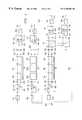
- FIG. 4is a simplified block diagram illustrating an optical system according to an embodiment of the present invention.
- FIG. 5is a partial block diagram illustrating the phenomenon that some undesirable optical signals will not interfere with the desired optical signals at the output of an optical system as illustrated in FIG. 4 .
- FIG. 6is a partial block diagram illustrating the phenomenon that some undesirable optical signals will not interfere with the desired optical signals at the output of an optical system as illustrated in FIG. 4 .
- FIG. 7is a graph illustrating simulated or modeled transmission and group delay characteristics of a first optical propagation path of FIG. 4;
- FIG. 8is a graph illustrating simulated or modeled transmission and group delay characteristics of a second optical propagation path of FIG. 4;
- FIG. 9is a graph depicting transmission and group delay of a stacked waveplate filter without using the present invention.
- FIG. 10is a graph depicting transmission and group delay of a stacked waveplate filter system according to an embodiment of the present invention.
- FIG. 11is a simplified block diagram illustrating an optical system in according to an embodiment of the present invention.
- a stacked waveplate filter 1100is made up of a plurality of substantially aligned individual waveplates 1106 a, b, c.
- each waveplateis formed of a birefringent crystal, as will be understood by those of skill in the art.
- Fast and slow axes 1107 a, b, c 1108 a, b, c, for each waveplate,are illustrated.
- an optical propagation path 1109passes successively through the waveplates 1106 a, b, c.
- the input, 1110which enters the first waveplate 1106 a has, in this example, vertical polarization, denoted by a vertical arrow 1110 a.
- the input signal, 1110After passing through the stacked waveplate filter 1100 , the input signal, 1110 , is decomposed into two components with different polarizations.
- One component, 1112has vertical polarization represented by a vertical arrow
- the other component, 1114has horizontal polarization, orthogonal to the first polarization, represented by a horizontal arrow.
- the configuration illustrated in FIG. 1substantially provides two optical paths.
- the first optical pathbegins with the input 1110 having vertical polarization and output 1112 having vertical polarization (designated the Vertical-Vertical path).
- the second pathhas input 1110 with vertical polarization and output 1114 with horizontal polarization (designated the Vertical-Horizontal path).
- FIGS. 2 and 3illustrate (modeled or simulated) transmission ( 1208 ) and group delay ( 1210 ) for the Vertical-Vertical path (FIG. 2) and for Vertical-Horizontal path (FIG. 3 ).
- FIGS. 2 and 3illustrate that the stacked waveplate of FIG. 1 operates as a periodic optical filter, i.e. providing output defining a transmission curve which (as a function of wavelength) is periodic.
- Comparison of FIGS. 2 and 3illustrates that chromatic dispersion characteristics within each transmission band ( 1212 a, b, c for FIG. 2 and 1312 a, b for FIG. 3) have substantially opposite shapes (i.e. have group delay peaks in the middle of transmission bands for FIG.
- FIGS. 2 and 3have group delay troughs in the middle of the transmission bands for FIG. 3 ), i.e. that the periodicity of the two outputs from the stacked waveplates (respectively illustrated in FIGS. 2 and three) is complementary.
- dispersionis expressed as group delay in units of picoseconds (ps). Dispersion is often characterized as picoseconds/km-nm. Transmission is shown in FIG. 3 and FIG. 2 as transmission loss ratio expressed in decibels (dB) (as a function of wavelength expressed in nanometers (nm)).
- One embodiment of the present inventioninvolves the recognition of the opposite or inverted nature of the dispersion characteristics for these two different optical paths and/or a manner in which these features of the dispersion characteristics can be used to compensate the chromatic dispersion (i.e. to substantially reduce or eliminate chromatic dispersion) e.g. caused by a stacked waveplate filter.
- FIG. 4illustrates a simplified diagram of a double stage stacked-waveplate optical system according to one embodiment of the present invention.
- Many double stage stacked-waveplate systemssuch as described in U.S. Pat. Nos. 5,694,233 and 5,912,748 (incorporated herein by reference) are used e.g. to generate more desirable spectra or to provide better performance.
- the resulting chromatic dispersionmight be significant.
- the system presented in FIG. 4shows that, with present invention, the resulting chromatic dispersion can be significantly reduced or compensated.
- an incoming signal 400passes through an optical fiber 800 and a collimator 810 to enter the system.
- the input optical signal 400is then decomposed by a beam displacer 10 into two components: signal 410 with horizontal polarization (represented in FIG. 4 by a dot) and signal 420 with vertical polarization (represented in FIG. 4 by a vertical line).
- component 410passes through a half-wave plate 20 so that its polarization is changed to vertical, the resulting signal being designated as 430 .
- optical signals 430 and 420have the same polarization, they are spatially separated.
- Optical signals 430 and 420then pass through a stacked waveplate filter 30 made up of a plurality of substantially aligned individual waveplates 30 a, 30 b, and 30 c.
- the stacked waveplate filterprovides temperature compensation (reduces excursions from desired performance caused by changes in component temperature) such as by selecting two or more waveplates or waveplate components with thermal performance which cancel one another out, e.g. as described in U.S. patent application Ser. No. 09/020,706 titled Temperature Insensitive Polarization Filter, incorporated herein by reference.
- the output signals of stacked waveplate filter 30are two sets of two signals with orthogonal polarizations.
- the output signals corresponding with signal 430are signal 440 (with horizontal polarization) and signal 460 (with vertical polarization).
- the output signals corresponding to signal 420are signal 450 (with horizontal polarization) and signal 470 (with vertical polarization).
- Two polarization beamsplitters 40 and 50are then used to separate signals with different polarization. Signals with vertical polarization, 460 and 470 are separated from signals with horizontal polarization, 440 and 450 by these two polarization beamsplitters. Signals with the same polarization are spatially separated.
- Signal 470 with the vertical polarizationpasses through a half-waveplate 60 , and its polarization is changed to horizontal.
- the resulting signal with horizontal polarizationis designated as 480 .
- Signals 460 and 480pass through a beam displacer 90 and are combined into signal 510 .
- the signal 510is then passed through the collimator 820 into optical fiber 840 to enter the next stage of the system.
- Signal 440passes through a half-waveplate 70 so that its polarization is changed to vertical.
- the signal 450is passed through a glass 80 so that the index difference between the optical paths of signals 440 and 450 can be compensated.
- Signal 440goes through the optical path 10 - 20 - 30 - 40 - 50
- signal 450goes through the optical path 10 - 30 - 40 - 50 .
- the glass 80is provided. It is generally desirable to make the effective optical path length of the signals 440 , 450 substantially equal, as they reach the beam diverter 100 . As can be seen from FIG.
- the optical path of signal 440includes passage through wave plates 20 and 70 .
- the glass 80has proper optical properties (length, index of refraction, and the like) to increase the optical path length of signal 450 to match the optical path length of signal 440 .
- glass 200increases the path length of signal 660 to match the path length of signal 650 , in view of the passage of signal 650 through waveplates 170 and 190 , before reaching the beam diverter 210 .
- signals 440 and 450After passing through the half-waveplate 70 and glass 80 , signals 440 and 450 become signal 490 (with vertical polarization) and signal 500 (with horizontal polarization). These two signals are then combined into signal 520 by the beam displacer 100 . The signal 520 is then passed through the collimator 830 into optical fiber 850 to enter the next stage of the system.
- Signal 510is made up of signals 460 and 470 whose polarization is unchanged by the waveplate filter 30 .
- signal 520is made up of signals 440 and 450 whose polarization is changed by the waveplate filter 30 . To compensate for the dispersion induced by waveplate 30 , further manipulation is conducted.
- signal 510After passing through collimator 820 , optical fiber 840 , and collimator 870 , signal 510 is first decomposed into two signals with different polarization by beam displacer 160 . After passing through beam displacer 160 , the incoming signal 510 is decomposed into signal 620 (with horizontal polarization) and signal 630 (with vertical polarization). Signal 620 is then passed through the half-waveplate 170 , and its polarization is changed to vertical. This resulting signal with vertical polarization is designated as 640 . Although signal 640 and 630 have the same polarization, they are spatially separated.
- Signals 640 and 630then pass through a stacked waveplate filter 180 made up of a plurality of substantially aligned individual waveplates 180 a, 180 b, and 180 c.
- the output signals of stacked waveplate filter 180 corresponding with incoming signals 640 and 630are two sets of two signals with different polarizations orthogonal to each other.
- the output signals corresponding with the input signal 640are signal 650 (with horizontal polarization) and signal 670 (with vertical polarization).
- the output signals corresponding with the input signal 630are signal 660 (with horizontal polarization) and signal 680 (with vertical polarization).
- signal 510is made up of signal 460 and 470 whose polarization is not changed by the waveplate filter 30 , signals 650 and 660 whose polarization is changed by the waveplate filter 180 are desired. This way, the chromatic dispersion caused by stacked waveplate filters 30 and 180 can be compensated.
- signals 650 and 660which have horizontal polarization and are spatially separated
- the polarization of one of themneeds to be changed.
- Signal 650is passed through half-waveplate 190 , and its polarization is then changed to vertical. The resulting signal is designated as 690 .
- a glass 200is used for signal 660 .
- the signal 660(with vertical polarization) passes through the glass 200 without polarization change, and the resulting signal is designated as 700 .
- Signal 690(with vertical polarization) and signal 700 (with horizontal polarization) are combined together in the beam displacer 210 .
- the resulting signalis designated as 710 .
- the signal 710is then passed through collimator 890 to enter optical fiber, systems, or network.
- Signal 670 and 680(with vertical polarization) will diverge after they pass through 190 - 210 and 200 - 210 respectively as illustrated in FIG. 5 .
- the signal 670(with vertical polarization) becomes signal 670 b (with horizontal polarization) after it passes through the half-waveplate 190 .
- the signal 680(with vertical polarization) becomes signal 680 b (with vertical polarization) after it passes through the glass 200 .
- the signals 670 b and 680 bwill not converge with the signals 690 and 700 in the beam displacer 210 ; therefore, their effects are not taken into account here.
- signal 520After passing through collimator 830 (FIG. 4 ), optical fiber 850 , and collimator 860 , signal 520 is first decomposed into two signals with different polarization by the beam displacer 110 . After passing through the beam displacer 110 , signal 520 is decomposed into signal 530 (with horizontal polarization) and signal 540 (with vertical polarization). Signal 530 is then passed through the half-waveplate 120 , and its polarization is then changed to vertical. The resulting signal (with vertical polarization) is designated as 550 . Although signals 540 and 550 have the same polarization, they are spatially separated.
- Signals 540 and 550then pass through a stacked waveplate filter 130 made up of a plurality of substantially aligned individual waveplates 130 a, 130 b, and 130 c.
- the output signals of stacked waveplate filter 130 corresponding with incoming signals 540 and 550are two sets of two signals with different polarization orthogonal to each other.
- the output signals corresponding with signal 550are signal 560 (with horizontal polarization) and signal 580 (with vertical polarization).
- the output signals corresponding with signal 540are signal 570 (with horizontal polarization) and the signal 590 (with vertical polarization).
- signal 520is made up of signal 440 and 450 whose polarization is changed by the waveplate filter 30 , signals 580 and 590 whose polarization is not changed by the waveplate filter 130 is desired. This way, the chromatic dispersion caused by stacked waveplate filters 30 and 130 can be compensated.
- signals 580 and 590which have the vertical polarization and are spatially separated
- the polarization of one of themneeds to be changed.
- Signal 590is passed through the half waveplate 140 , and its polarization is then changed into horizontal. The resulting signal is designated as 600 .
- Signal 580 (with vertical polarization) and signal 600 (with horizontal polarization)are then combined by the beam displacer 150 into signal 610 .
- the signal 610is then passed through collimator 880 to enter optical fiber, systems, or network.
- Signal 560 and 570 with horizontal polarizationwill diverge after they pass through 150 and 140 - 150 respectively as illustrated in FIG. 6 .
- Signal 570(with horizontal polarization) becomes signal 570 b (with vertical polarization) after it passes through the half-waveplate 140 .
- signals 560 b and 570 bwill not converge with signals 580 and 600 in the beam displacer 150 ; therefore, their effects are not taken into account here.
- FIG. 7illustrates modeled chromatic dispersion characteristics and transmission of the first optical path 10 - 30 - 90 - 160 - 180 - 210 (Vertical-Vertical-Vertical-Horizontal) and FIG. 8 illustrates modeled chromatic dispersion characteristics and transmission of the second optical path 10 - 30 - 100 - 110 - 130 - 150 (Vertical-Horizontal-Vertical-Vertical).
- FIGS. 7 and 8show transmission loss (expressed as decibels) 510 , 610 and group delay 512 612 (simulated or modeled) as a function of wavelength (in nanometers). These simulation results illustrate that chromatic dispersion can be compensated significantly with the method and apparatus of the present invention. The small peaks shown in FIG. 7 and FIG. 8 are believed to be due to numerical error.
- FIG. 9illustrates the relatively high amount of chromatic dispersion (group delay) 710 occurring within a transmission band 712 of a typical stacked waveplate filter such as described in U.S. Pat. No. 5,694,233 (incorporated herein by reference) in the absence of the present invention.
- FIG. 9illustrates that typical previous waveplate filters were subject to relatively high dispersion such as 5 to 9 ps (or more) in at least part of the transmission band 714 .
- FIG. 10illustrates that when a stacked waveplate filter apparatus is modified, e.g., as illustrated in FIG. 4, the group delay 810 within a high-transmission region 814 of the transmission curve 812 is substantially reduced (such as generally having a magnitude less than about 5 ps).
- the shape of the dispersion waveform which is achieved, as shown in FIG. 10,is particularly advantageous in that the dispersion is relatively flat over a relatively wide region of the passband (e.g. relatively flat from about 1555.975 nm to about 1556.3 nm, in the example of FIG. 10 ), in contrast to systems which provide only relatively narrow bandwidths in which the lowest (albeit possibly greater than about 5 ps) dispersion occurs.
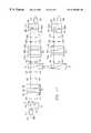
- FIG. 11illustrates a simplified diagram of another double stage stacked-waveplate optical system according to one embodiment of the present invention. Reference numerals in FIG. 11 which are found in FIG. 4 refer to corresponding components.
- an incoming signal 400passes through an optical fiber 800 and a collimator 810 to enter the system.
- the input signal 400is then decomposed into two signal components: signal 410 (with horizontal polarization) and signal 420 (with vertical polarization) by the beam displacer 10 .
- Signal 410is then passed through the half-waveplate 20 , and its polarization is changed to vertical.
- the resulting signal with vertical polarizationis designated as 430 .
- Signals 420 and 430then pass through the stacked waveplate filter 30 made up of a plurality of substantially aligned individual waveplates 30 a, 30 b, and 30 c. As illustrated in FIG.
- the output signals of stacked waveplate filter 30 corresponding with incoming signals 430 and 420are two sets of two signals with orthogonal polarizations.
- the output signals corresponding with input signal 430are signal 440 (with horizontal polarization) and signal 460 (with vertical polarization).
- the output signals corresponding with input signal 420are signal 450 (with horizontal polarization) and signal 470 (with vertical polarization).
- Two polarization beamsplitters 40 and 50are used to separate signals with different polarizations.
- the signals with vertical polarization, 460 and 470are separated from signals with horizontal polarization, 440 and 450 , by the two polarization beamsplitters 40 and 50 . Signals with the same polarization are spatially separated. Signal 460 and 470 are then passed through stacked waveplate filters 960 made up of a plurality of substantially aligned individual waveplates 960 a, 960 b, and 960 c. As illustrated in FIG. 1, the output signals of stacked waveplate filter 960 corresponding with incoming signals 460 and 470 are two sets of two signals with different polarization orthogonal to each other respectively.
- the output signals corresponding with signal 460are signal 1480 (with vertical polarization) and signal 1500 (with horizontal polarization).
- the output signals corresponding with the signal 470are signal 1490 (with vertical polarization) and signal 1510 (with vertical polarization).
- signals 460 and 470have polarization which is not changed by the stacked waveplate filter 30 , signal 1500 and 1510 whose polarization is changed by stack waveplate filter 960 are desired. This way, the chromatic dispersion caused by the stacked waveplate filters 30 and 960 can be compensated.
- the polarization of one of themneeds to be changed.
- Signal 1500passes through the half-waveplate 980 and, its polarization is then changed to vertical polarization. The resulting signal is then designated as signal 1520 .
- Signal 1510is passed through the glass 990 since there is index different between two optical paths 10 - 20 - 30 - 40 - 960 through which the signal 1500 goes and 10 - 30 - 40 - 960 through which the signal 1510 goes.
- the polarization of 1510is unchanged and the resulting signal is designated as 1530 .
- Signal 1520 (with vertical polarization) and signal 1530 (with horizontal polarization)are combined in the stacked waveplate filter 900 , and the resulting signal is designated 1540 .
- Signal 1540is then passed through collimator 820 to enter optical fiber, systems, or network. Signals 1480 and 1490 will not interfere with signal 1500 and 1510 as demonstrated in FIG. 5 . Therefore, their effects are not taken into account.
- the signals with horizontal polarization, 440 and 450are separated from signals with horizontal polarization, 460 and 470 by the two polarization beamsplitters 40 and 50 . These signals have the same polarization and spatially separated.
- Signal 440 and 450are then passed through stacked waveplate filters 970 made up of a plurality of substantially aligned individual waveplates 970 a, 970 b, and 970 c. As illustrated in FIG. 1, the output signals of stacked waveplate filter 970 corresponding with incoming signals 440 and 450 are two sets of two signals with orthogonal polarizations.
- the output signals corresponding with signal 440are signal 1550 (with vertical polarization) and signal 1570 (with horizontal polarization).
- the output signals corresponding with signal 450are signal 1560 (with vertical polarization) and signal 1580 (with horizontal polarization). Since the polarization of signals 440 and 450 is changed by the stacked waveplate filter 30 , signals 1570 and 1580 whose polarization is not changed by the stacked waveplate filter 970 are desirable. This way, the chromatic dispersion caused by the stacked waveplate filters 30 and 970 can be compensated. To combine signals 1570 and 1580 (which have the same polarization and are spatially separated) without energy loss, the polarization of one of them needs to be changed. Signal 1570 passes through the half-waveplate 910 and is changed into vertical polarization. The resulting signal is designated as signal 1590 .
- Signal 1580passes through the glass 920 since there is an index difference between the two optical paths ( 10 - 20 - 30 - 40 - 50 - 970 through which the signal 1570 goes and 10 - 30 - 40 - 50 - 970 through which the signal 1580 goes).
- the polarization of signal 1580is unchanged and the resulting signal is designated as signal 1600 .
- Signal 1590 with vertical polarization and signal 1600 with horizontal polarizationare combined in beam displacer 930 , and the resulting signal is designated as signal 1610 .
- the signal 1610is then passed through collimator 830 to enter optical fiber, systems, or network. Signals 1550 and 1560 will not interfere with signal 1570 and 1580 after entering beam displacer 930 as demonstrated in FIG. 5 . Therefore, their effects are not taken into account.
- one embodiment of the present inventionprovides apparatus usable for providing reduced dispersion optical signals which includes a first device 810 , 10 , 20 for receiving a first optical signal 400 and outputting second and third spaced-apart optical signals 420 , 430 ; a stacked waveplate filter device(s) 30 for receiving the second and third signals and outputting fourth and fifth spaced apart output pairs, the fourth output pair comprising sixth and seventh signals 440 , 460 and eighth and ninth signals 450 , 470 ; a second device(s) 40 , 60 , 90 , 820 , 840 , 870 , 160 , 170 for directing the seventh and ninth signals, to a second stacked waveplate filter device(s) 180 , which outputs tenth 650 , 670 and eleventh 660 , 680 signal pairs; third device(s) 50 , 70 , 80 , 100 , 830 , 850 , 860 , 110 , 120 for directing the sixth and eighth signals
- one embodiment of the present inventionprovides apparatus usable for providing reduced dispersion optical signals including first device(s) 810 , 10 , 20 for receiving a first optical signal 400 and outputting second and third spaced-apart optical signals 420 , 430 ; a stacked waveplate filter device(s) 30 for receiving the second and third signals and outputting fourth and fifth spaced apart output pairs, the fourth output pair comprising sixth and seventh signals 440 , 460 and eighth and ninth signals 450 , 470 ; second device(s) ( 40 ) for directing the seventh and ninth signals, to a second stacked waveplate filter device(s) ( 960 ) which outputs tenth ( 1480 , 1500 ) and eleventh ( 1490 , 1510 ) signal pairs; third device(s) ( 50 ) for directing the sixth and eighth signals, to a third stacked waveplate filter device(s), ( 970 ) which outputs a twelfth ( 1550 , 1570 ) and thirteenth, ( 1560
- one embodiment of the present inventionprovides apparatus for reducing optical signal dispersion which includes device(s) 810 , 10 , 30 , 40 , 50 for receiving at least a first optical signal and outputting at least second 460 , 470 and third 440 , 450 optical signals, the device(s) for receiving including first optical filter device(s) 30 defining substantially periodic transmissions of the second and third optical signals, as a function of wavelength, the first optical filter device(s) imparting a first dispersion; device(s) 960 , 980 , 990 , 900 , 820 for receiving the second optical signal and outputting a fourth signal 1540 , the device(s) for receiving the second optical signal comprising a second periodic optical filter 960 , the second periodic optical filter imparting a second dispersion which substantially compensates the first dispersion; and device(s) 970 , 910 , 920 , 930 , 830 for receiving the third optical signal and outputting a fifth signal 1610 , the
- the present inventioncan achieve a substantial reduction in dispersion along an optical path.
- the present inventionprovides for a reduction in dispersion of a discrete optical device such as a stacked waveplate filter, compared to the amount of dispersion which would occur in a typical stacked waveplate or similar device in the absence of using the present invention.
- the present inventioncan achieve such reduction in dispersion while providing the desired types of output (typically, output of two orthogonal polarized paths) and preferably can provide such reduction in dispersion using a combination of, and/or pathway through components, each one of which is typically readily available, including providing a pathway through a sequential plurality of stacked waveplate devices with appropriate polarization change or control. Accordingly, the present invention is able to achieve reduction in dispersion at relatively low cost.
- the present inventioncan be embodied in an optical router, it is possible to use configurations of the present invention and other types of devices such as switches, hubs, bridges, multiplexers, demultiplexers and the like. Although the present invention is believed to be particularly useful in the context of WDM signals, it is also possible to implement the present invention for use with other types of signals including unmultiplexed signals. Although the present invention was illustrated in connection with particular polarization sequences (i.e. Vertical-Vertical-Vertical-Horizontal; Vertical-Horizontal-Vertical-Vertical) other polarization sequences can also be used.
- polarization sequencesi.e. Vertical-Vertical-Vertical-Horizontal; Vertical-Horizontal-Vertical-Vertical
- other polarization sequencescan also be used.
- the present inventionin various embodiments, includes components, methods, processes, systems and/or apparatus substantially as depicted and described herein, including various embodiments, subcombinations, and subsets thereof. Those of skills in the art will understand how to make and use the present invention after understanding the present disclosure.
- the present inventionin various embodiments, includes providing devices and processes in the absence of items not depicted and/or described herein or in various embodiment hereof, including in the absence of such items as may have been used in previous devices or processes, e.g. for improving performance, achieving ease and/or reducing cost of implementation.
- the present inventionincludes items which are novel, and terminology adapted from previous and/or analogous technologies, for convenience in describing novel items or processes, do not necessarily retain all aspects of conventional usage of such terminology.
Landscapes
- Physics & Mathematics (AREA)
- General Physics & Mathematics (AREA)
- Optics & Photonics (AREA)
- Engineering & Computer Science (AREA)
- Computer Networks & Wireless Communication (AREA)
- Signal Processing (AREA)
- Chemical & Material Sciences (AREA)
- Dispersion Chemistry (AREA)
- Electromagnetism (AREA)
- Optical Communication System (AREA)
Abstract
Description
Claims (76)
Priority Applications (3)
| Application Number | Priority Date | Filing Date | Title |
|---|---|---|---|
| US09/469,336US6396609B1 (en) | 1999-12-20 | 1999-12-20 | Dispersion compensation for optical systems |
| AU29110/01AAU2911001A (en) | 1999-12-20 | 2000-12-19 | Dispersion compensation for optical systems |
| PCT/US2000/034888WO2001047163A1 (en) | 1999-12-20 | 2000-12-19 | Dispersion compensation for optical systems |
Applications Claiming Priority (1)
| Application Number | Priority Date | Filing Date | Title |
|---|---|---|---|
| US09/469,336US6396609B1 (en) | 1999-12-20 | 1999-12-20 | Dispersion compensation for optical systems |
Publications (1)
| Publication Number | Publication Date |
|---|---|
| US6396609B1true US6396609B1 (en) | 2002-05-28 |
Family
ID=23863383
Family Applications (1)
| Application Number | Title | Priority Date | Filing Date |
|---|---|---|---|
| US09/469,336Expired - Fee RelatedUS6396609B1 (en) | 1999-12-20 | 1999-12-20 | Dispersion compensation for optical systems |
Country Status (3)
| Country | Link |
|---|---|
| US (1) | US6396609B1 (en) |
| AU (1) | AU2911001A (en) |
| WO (1) | WO2001047163A1 (en) |
Cited By (10)
| Publication number | Priority date | Publication date | Assignee | Title |
|---|---|---|---|---|
| WO2002099357A1 (en)* | 2001-06-04 | 2002-12-12 | Oplink Communications, Inc. | Optical signal interleaver and deinterleaver devices with chromatic dispersion compensation |
| US6591023B1 (en)* | 1997-10-15 | 2003-07-08 | Robert Bosch Gmbh | Optical transmitter having a modulation-capable wavelength-stable laser source |
| US6687054B2 (en)* | 2000-06-07 | 2004-02-03 | Cirvine Corporation | Apparatus and method for low dispersion in communications |
| US6748150B1 (en)* | 2003-04-30 | 2004-06-08 | Lucent Technologies Inc. | Apparatus and method for managing dispersion within an optical add/drop module |
| US20040148674A1 (en)* | 2003-01-31 | 2004-08-05 | Simmons Bennie F. | Protective sideshield with comfort safety wing |
| US6809863B2 (en)* | 2001-06-07 | 2004-10-26 | Cirvine Corporation | Low dispersion filters |
| US7349089B1 (en)* | 2005-06-28 | 2008-03-25 | Hrl Laboratories, Llc | High transmission multi-wavelength filter and method |
| US20090288007A1 (en)* | 2008-04-05 | 2009-11-19 | Social Communications Company | Spatial interfaces for realtime networked communications |
| WO2011015143A1 (en)* | 2009-08-05 | 2011-02-10 | 华为技术有限公司 | Optical device and optical component thereof |
| US10439302B2 (en) | 2017-06-08 | 2019-10-08 | Pct International, Inc. | Connecting device for connecting and grounding coaxial cable connectors |
Citations (56)
| Publication number | Priority date | Publication date | Assignee | Title |
|---|---|---|---|---|
| US3501640A (en) | 1967-01-13 | 1970-03-17 | Ibm | Optical communication system |
| US4019807A (en) | 1976-03-08 | 1977-04-26 | Hughes Aircraft Company | Reflective liquid crystal light valve with hybrid field effect mode |
| US4039252A (en) | 1972-12-13 | 1977-08-02 | Energy Systems, Ltd. | Field-effect liquid crystal-type display device |
| US4378955A (en) | 1979-08-03 | 1983-04-05 | Hughes Aircraft Company | Method of and apparatus for a multimode image display with a liquid crystal light valve |
| US4461543A (en) | 1982-03-26 | 1984-07-24 | Sperry Corporation | Electro optic switch |
| US4516837A (en) | 1983-02-22 | 1985-05-14 | Sperry Corporation | Electro-optical switch for unpolarized optical signals |
| US4566761A (en) | 1984-09-13 | 1986-01-28 | Gte Laboratories Incorporated | Birefringent optical wavelength multiplexer/demultiplexer |
| US4685773A (en) | 1984-09-13 | 1987-08-11 | Gte Laboratories Incorporated | Birefringent optical multiplexer with flattened bandpass |
| US4737003A (en) | 1983-12-23 | 1988-04-12 | Hitachi, Ltd. | Optical switching device utilizing multiple quantum well structures between intersecting waveguides |
| US4893931A (en) | 1987-03-13 | 1990-01-16 | Thomson-Csf | Method for the detection of polarization couplings in a birefringent optical system and application of this method to the assembling of the components of an optical system |
| US4896947A (en) | 1986-10-24 | 1990-01-30 | Hoffman-La Roche Inc. | Liquid crystal display cell |
| US4952030A (en) | 1987-09-04 | 1990-08-28 | Asahi Glass Company, Ltd. | Liquid crystal display device with a 50°-80° twist angle |
| US4999619A (en) | 1987-06-10 | 1991-03-12 | U.S. Philips Corporation | Electro-optic display device for use in the reflection mode |
| US5105289A (en) | 1988-07-14 | 1992-04-14 | Seiko Epson Corporation | Reflection type electrooptical device and a projection type display apparatus using the same |
| US5185824A (en) | 1991-10-29 | 1993-02-09 | At&T Bell Laboratories | Optical switch incorporating molded optical waveguide elements |
| US5477350A (en) | 1993-06-01 | 1995-12-19 | General Electric Company | Interferometric spatial switch for polarized or unpolarized light using liquid crystal |
| US5555113A (en) | 1990-03-23 | 1996-09-10 | U.S. Philips Corporation | Liquid crystal display device with twist angle φ of 70° to 90°and alignment to polarization direction angle between φ/2+30°and φ/2+60° |
| US5596661A (en) | 1994-12-28 | 1997-01-21 | Lucent Technologies Inc. | Monolithic optical waveguide filters based on Fourier expansion |
| US5608652A (en) | 1995-05-12 | 1997-03-04 | Intel Corporation | Reducing blocking effects in block transfer encoders |
| US5623360A (en) | 1991-12-12 | 1997-04-22 | Essex Corporation | Time delay beam formation |
| US5680490A (en) | 1995-09-08 | 1997-10-21 | Lucent Technologies Inc. | Comb splitting system and method for a multichannel optical fiber communication network |
| US5694233A (en)* | 1996-07-23 | 1997-12-02 | Macro-Vision Communications, Llc | Switchable wavelength router |
| US5712704A (en) | 1995-09-13 | 1998-01-27 | Photonetics | Appliance for measuring polarization mode dispersion and corresponding measuring process |
| US5724165A (en) | 1996-07-23 | 1998-03-03 | Macro-Vision Communications, L.L.C. | Fault-tolerant optical routing switch |
| US5726723A (en) | 1996-01-31 | 1998-03-10 | Technology Research International Corporation | Sub-twisted nematic liquid crystal display |
| US5740288A (en) | 1995-02-22 | 1998-04-14 | E-Tek Dynamics, Inc. | Variable polarization beam splitter, combiner and mixer |
| US5809190A (en) | 1996-11-13 | 1998-09-15 | Applied Fiber Optics, Inc. | Apparatus and method of making a fused dense wavelength-division multiplexer |
| WO1998047254A2 (en) | 1997-04-15 | 1998-10-22 | Chorum Technologies, Inc. | N x M OPTICAL WAVELENGTH ROUTING SWITCH |
| US5854666A (en) | 1996-11-28 | 1998-12-29 | Nec Corporation | Liquid crystal display device having particular twist angle, .increment.n d, .increment.ε, and threshold voltage |
| US5867291A (en) | 1996-10-29 | 1999-02-02 | Chorum Technologies Inc. | Programmable wavelength router |
| US5870164A (en) | 1997-06-20 | 1999-02-09 | International Business Machines Corporation | Polarization dependent twisted nematic liquid crystal devices for reflective spatial light modulators |
| US5877876A (en) | 1992-10-09 | 1999-03-02 | Apeldyn Corporation | Diffractive optical switch with polarizing beam splitters |
| US5883687A (en) | 1997-04-02 | 1999-03-16 | International Business Machines Corporation | Polarization independent liquid crystal phase gratings for reflective spatial light modulators |
| EP0905936A2 (en) | 1997-08-27 | 1999-03-31 | Cambrian Systems Corporation | WDM optical network with passive pass-through at each node |
| WO1999028778A1 (en) | 1997-11-28 | 1999-06-10 | Chorum Technologies, Inc. | Ferroelectric liquid crystal devices with twisted structure |
| US5912748A (en)* | 1996-07-23 | 1999-06-15 | Chorum Technologies Inc. | Switchable wavelength router |
| US5933207A (en) | 1995-10-23 | 1999-08-03 | Hughes Electronics Corporation | Reflective-type liquid crystal displays using mixed-mode twist nematic cells |
| US5936697A (en) | 1996-06-07 | 1999-08-10 | International Business Machines Corporation | Self-compensated twisted nematic mode for reflective light valves |
| US5943151A (en)* | 1996-03-11 | 1999-08-24 | Pirelli Cavi S.P.A. | Mehtod of selectively compensating for the chromatic dispersion of optical signals |
| US5946116A (en) | 1997-04-02 | 1999-08-31 | Wu; Kuang-Yi | 1 X N digitally programmable optical routing switch |
| WO1999045738A1 (en) | 1998-03-06 | 1999-09-10 | Chorum Technologies, Inc. | Optical add/drop wavelength switch |
| WO1999049605A1 (en) | 1998-03-26 | 1999-09-30 | Chorum Technologies Inc. | Programmable optical add/drop multiplexer |
| US5963291A (en) | 1997-07-21 | 1999-10-05 | Chorum Technologies Inc. | Optical attenuator using polarization modulation and a feedback controller |
| US6005697A (en) | 1996-07-23 | 1999-12-21 | Macro-Vision Communications, L.L.C. | Multi-wavelength cross-connect optical network |
| US6067178A (en) | 1997-09-16 | 2000-05-23 | Oplink Communications, Inc. | Multiple wavelength division multiplexer with reduced loss |
| US6094246A (en) | 1998-01-06 | 2000-07-25 | Chorum Technologies | Acute twist nematic liquid crystal electro-optic modulator for use in an infrared optical communication system having extinction ratio of -25db |
| US6097451A (en) | 1995-10-26 | 2000-08-01 | Hornell International Ab | Liquid crystal shutter with low twisted nematic liquid crystal cells driven with a low frequency or DC voltage |
| US6111625A (en) | 1996-09-02 | 2000-08-29 | Hitachi, Ltd. | Active matrix Type liquid crystal display device |
| US6130971A (en) | 1998-08-06 | 2000-10-10 | Avanex Corporation | Fiber optic dense wavelength division multiplexer with a phase differential method of wavelength separation utilizing a polarization beam splitter and a nonlinear interferometer |
| US6134358A (en) | 1998-08-27 | 2000-10-17 | Chorum Technologies Inc. | N x N switch array with reduced components |
| US6137604A (en) | 1996-12-04 | 2000-10-24 | Tyco Submarine Systems, Ltd. | Chromatic dispersion compensation in wavelength division multiplexed optical transmission systems |
| US6144494A (en) | 1995-07-26 | 2000-11-07 | Fujitsu Limited | Virtually imaged phased array (VIPA) having spacer element and optical length adjusting element |
| US6151158A (en)* | 1997-08-11 | 2000-11-21 | Fujitsu Limited | Method and device for optical amplification and system having the device |
| US6169604B1 (en) | 1999-02-10 | 2001-01-02 | Avanex Corporation | Nonlinear interferometer for fiber optic dense wavelength division multiplexer utilizing a phase bias element to separate wavelengths in an optical signal |
| US6208442B1 (en) | 1998-03-26 | 2001-03-27 | Chorum Technologies, Inc. | Programmable optical multiplexer |
| US6212313B1 (en) | 2000-01-31 | 2001-04-03 | Oplink Communications, Inc. | Optical interleaver |
- 1999
- 1999-12-20USUS09/469,336patent/US6396609B1/ennot_activeExpired - Fee Related
- 2000
- 2000-12-19AUAU29110/01Apatent/AU2911001A/ennot_activeAbandoned
- 2000-12-19WOPCT/US2000/034888patent/WO2001047163A1/enactiveApplication Filing
Patent Citations (62)
| Publication number | Priority date | Publication date | Assignee | Title |
|---|---|---|---|---|
| US3501640A (en) | 1967-01-13 | 1970-03-17 | Ibm | Optical communication system |
| US4039252A (en) | 1972-12-13 | 1977-08-02 | Energy Systems, Ltd. | Field-effect liquid crystal-type display device |
| US4019807A (en) | 1976-03-08 | 1977-04-26 | Hughes Aircraft Company | Reflective liquid crystal light valve with hybrid field effect mode |
| US4378955A (en) | 1979-08-03 | 1983-04-05 | Hughes Aircraft Company | Method of and apparatus for a multimode image display with a liquid crystal light valve |
| US4461543A (en) | 1982-03-26 | 1984-07-24 | Sperry Corporation | Electro optic switch |
| US4516837A (en) | 1983-02-22 | 1985-05-14 | Sperry Corporation | Electro-optical switch for unpolarized optical signals |
| US4737003A (en) | 1983-12-23 | 1988-04-12 | Hitachi, Ltd. | Optical switching device utilizing multiple quantum well structures between intersecting waveguides |
| US4566761A (en) | 1984-09-13 | 1986-01-28 | Gte Laboratories Incorporated | Birefringent optical wavelength multiplexer/demultiplexer |
| US4685773A (en) | 1984-09-13 | 1987-08-11 | Gte Laboratories Incorporated | Birefringent optical multiplexer with flattened bandpass |
| US4896947A (en) | 1986-10-24 | 1990-01-30 | Hoffman-La Roche Inc. | Liquid crystal display cell |
| US4893931A (en) | 1987-03-13 | 1990-01-16 | Thomson-Csf | Method for the detection of polarization couplings in a birefringent optical system and application of this method to the assembling of the components of an optical system |
| US4999619A (en) | 1987-06-10 | 1991-03-12 | U.S. Philips Corporation | Electro-optic display device for use in the reflection mode |
| US4952030A (en) | 1987-09-04 | 1990-08-28 | Asahi Glass Company, Ltd. | Liquid crystal display device with a 50°-80° twist angle |
| US5105289A (en) | 1988-07-14 | 1992-04-14 | Seiko Epson Corporation | Reflection type electrooptical device and a projection type display apparatus using the same |
| US5555113A (en) | 1990-03-23 | 1996-09-10 | U.S. Philips Corporation | Liquid crystal display device with twist angle φ of 70° to 90°and alignment to polarization direction angle between φ/2+30°and φ/2+60° |
| US5185824A (en) | 1991-10-29 | 1993-02-09 | At&T Bell Laboratories | Optical switch incorporating molded optical waveguide elements |
| US5623360A (en) | 1991-12-12 | 1997-04-22 | Essex Corporation | Time delay beam formation |
| US5877876A (en) | 1992-10-09 | 1999-03-02 | Apeldyn Corporation | Diffractive optical switch with polarizing beam splitters |
| US5477350A (en) | 1993-06-01 | 1995-12-19 | General Electric Company | Interferometric spatial switch for polarized or unpolarized light using liquid crystal |
| US5596661A (en) | 1994-12-28 | 1997-01-21 | Lucent Technologies Inc. | Monolithic optical waveguide filters based on Fourier expansion |
| US5740288A (en) | 1995-02-22 | 1998-04-14 | E-Tek Dynamics, Inc. | Variable polarization beam splitter, combiner and mixer |
| US5608652A (en) | 1995-05-12 | 1997-03-04 | Intel Corporation | Reducing blocking effects in block transfer encoders |
| US6144494A (en) | 1995-07-26 | 2000-11-07 | Fujitsu Limited | Virtually imaged phased array (VIPA) having spacer element and optical length adjusting element |
| US5680490A (en) | 1995-09-08 | 1997-10-21 | Lucent Technologies Inc. | Comb splitting system and method for a multichannel optical fiber communication network |
| US5712704A (en) | 1995-09-13 | 1998-01-27 | Photonetics | Appliance for measuring polarization mode dispersion and corresponding measuring process |
| US5933207A (en) | 1995-10-23 | 1999-08-03 | Hughes Electronics Corporation | Reflective-type liquid crystal displays using mixed-mode twist nematic cells |
| US6097451A (en) | 1995-10-26 | 2000-08-01 | Hornell International Ab | Liquid crystal shutter with low twisted nematic liquid crystal cells driven with a low frequency or DC voltage |
| US5726723A (en) | 1996-01-31 | 1998-03-10 | Technology Research International Corporation | Sub-twisted nematic liquid crystal display |
| US5943151A (en)* | 1996-03-11 | 1999-08-24 | Pirelli Cavi S.P.A. | Mehtod of selectively compensating for the chromatic dispersion of optical signals |
| US5936697A (en) | 1996-06-07 | 1999-08-10 | International Business Machines Corporation | Self-compensated twisted nematic mode for reflective light valves |
| US5694233A (en)* | 1996-07-23 | 1997-12-02 | Macro-Vision Communications, Llc | Switchable wavelength router |
| US6005697A (en) | 1996-07-23 | 1999-12-21 | Macro-Vision Communications, L.L.C. | Multi-wavelength cross-connect optical network |
| US6175432B1 (en) | 1996-07-23 | 2001-01-16 | Chorum Technologies Inc. | Multi-wavelength cross-connect optical network |
| US5724165A (en) | 1996-07-23 | 1998-03-03 | Macro-Vision Communications, L.L.C. | Fault-tolerant optical routing switch |
| US5912748A (en)* | 1996-07-23 | 1999-06-15 | Chorum Technologies Inc. | Switchable wavelength router |
| US6111625A (en) | 1996-09-02 | 2000-08-29 | Hitachi, Ltd. | Active matrix Type liquid crystal display device |
| US5867291A (en) | 1996-10-29 | 1999-02-02 | Chorum Technologies Inc. | Programmable wavelength router |
| US5978116A (en) | 1996-10-29 | 1999-11-02 | Chorum Technologies Inc. | Programmable wavelength router |
| US6137606A (en) | 1996-10-29 | 2000-10-24 | Chorum Technologies, Inc. | Optical wavelength router |
| US5809190A (en) | 1996-11-13 | 1998-09-15 | Applied Fiber Optics, Inc. | Apparatus and method of making a fused dense wavelength-division multiplexer |
| US5854666A (en) | 1996-11-28 | 1998-12-29 | Nec Corporation | Liquid crystal display device having particular twist angle, .increment.n d, .increment.ε, and threshold voltage |
| US6137604A (en) | 1996-12-04 | 2000-10-24 | Tyco Submarine Systems, Ltd. | Chromatic dispersion compensation in wavelength division multiplexed optical transmission systems |
| US6166838A (en) | 1997-03-24 | 2000-12-26 | Chorum Technologies, Inc. | Optical add/drop wavelength switch |
| US5946116A (en) | 1997-04-02 | 1999-08-31 | Wu; Kuang-Yi | 1 X N digitally programmable optical routing switch |
| US5883687A (en) | 1997-04-02 | 1999-03-16 | International Business Machines Corporation | Polarization independent liquid crystal phase gratings for reflective spatial light modulators |
| WO1998047254A2 (en) | 1997-04-15 | 1998-10-22 | Chorum Technologies, Inc. | N x M OPTICAL WAVELENGTH ROUTING SWITCH |
| US5870164A (en) | 1997-06-20 | 1999-02-09 | International Business Machines Corporation | Polarization dependent twisted nematic liquid crystal devices for reflective spatial light modulators |
| US5963291A (en) | 1997-07-21 | 1999-10-05 | Chorum Technologies Inc. | Optical attenuator using polarization modulation and a feedback controller |
| US6151158A (en)* | 1997-08-11 | 2000-11-21 | Fujitsu Limited | Method and device for optical amplification and system having the device |
| EP0905936A2 (en) | 1997-08-27 | 1999-03-31 | Cambrian Systems Corporation | WDM optical network with passive pass-through at each node |
| US6067178A (en) | 1997-09-16 | 2000-05-23 | Oplink Communications, Inc. | Multiple wavelength division multiplexer with reduced loss |
| US6141076A (en) | 1997-11-28 | 2000-10-31 | Chorum Technologies, Inc. | Spatial light modulators constructed from ferroelectric liquid crystal devices with twisted structure |
| WO1999028778A1 (en) | 1997-11-28 | 1999-06-10 | Chorum Technologies, Inc. | Ferroelectric liquid crystal devices with twisted structure |
| US6094246A (en) | 1998-01-06 | 2000-07-25 | Chorum Technologies | Acute twist nematic liquid crystal electro-optic modulator for use in an infrared optical communication system having extinction ratio of -25db |
| US6201593B1 (en) | 1998-01-06 | 2001-03-13 | Chorum Technologies, Inc. | Optical communication system having a liquid crystal routing switch |
| WO1999045738A1 (en) | 1998-03-06 | 1999-09-10 | Chorum Technologies, Inc. | Optical add/drop wavelength switch |
| WO1999049605A1 (en) | 1998-03-26 | 1999-09-30 | Chorum Technologies Inc. | Programmable optical add/drop multiplexer |
| US6208442B1 (en) | 1998-03-26 | 2001-03-27 | Chorum Technologies, Inc. | Programmable optical multiplexer |
| US6130971A (en) | 1998-08-06 | 2000-10-10 | Avanex Corporation | Fiber optic dense wavelength division multiplexer with a phase differential method of wavelength separation utilizing a polarization beam splitter and a nonlinear interferometer |
| US6134358A (en) | 1998-08-27 | 2000-10-17 | Chorum Technologies Inc. | N x N switch array with reduced components |
| US6169604B1 (en) | 1999-02-10 | 2001-01-02 | Avanex Corporation | Nonlinear interferometer for fiber optic dense wavelength division multiplexer utilizing a phase bias element to separate wavelengths in an optical signal |
| US6212313B1 (en) | 2000-01-31 | 2001-04-03 | Oplink Communications, Inc. | Optical interleaver |
Non-Patent Citations (24)
Cited By (11)
| Publication number | Priority date | Publication date | Assignee | Title |
|---|---|---|---|---|
| US6591023B1 (en)* | 1997-10-15 | 2003-07-08 | Robert Bosch Gmbh | Optical transmitter having a modulation-capable wavelength-stable laser source |
| US6687054B2 (en)* | 2000-06-07 | 2004-02-03 | Cirvine Corporation | Apparatus and method for low dispersion in communications |
| WO2002099357A1 (en)* | 2001-06-04 | 2002-12-12 | Oplink Communications, Inc. | Optical signal interleaver and deinterleaver devices with chromatic dispersion compensation |
| US6809863B2 (en)* | 2001-06-07 | 2004-10-26 | Cirvine Corporation | Low dispersion filters |
| US20040148674A1 (en)* | 2003-01-31 | 2004-08-05 | Simmons Bennie F. | Protective sideshield with comfort safety wing |
| US6748150B1 (en)* | 2003-04-30 | 2004-06-08 | Lucent Technologies Inc. | Apparatus and method for managing dispersion within an optical add/drop module |
| US7349089B1 (en)* | 2005-06-28 | 2008-03-25 | Hrl Laboratories, Llc | High transmission multi-wavelength filter and method |
| US20090288007A1 (en)* | 2008-04-05 | 2009-11-19 | Social Communications Company | Spatial interfaces for realtime networked communications |
| WO2011015143A1 (en)* | 2009-08-05 | 2011-02-10 | 华为技术有限公司 | Optical device and optical component thereof |
| US10439302B2 (en) | 2017-06-08 | 2019-10-08 | Pct International, Inc. | Connecting device for connecting and grounding coaxial cable connectors |
| US10855003B2 (en) | 2017-06-08 | 2020-12-01 | Pct International, Inc. | Connecting device for connecting and grounding coaxial cable connectors |
Also Published As
| Publication number | Publication date |
|---|---|
| AU2911001A (en) | 2001-07-03 |
| WO2001047163A1 (en) | 2001-06-28 |
Similar Documents
| Publication | Publication Date | Title |
|---|---|---|
| US5841557A (en) | Method and apparatus for scrambling the polarization of signal lights forming a wavelength division multiplexed signal light | |
| USRE38289E1 (en) | Chromatic dispersion compensation in wavelength division multiplexed optical transmission systems | |
| EP0697775B1 (en) | Multiple-channel all-optical TDM-WDM converter and multiple-channel all-optical TDM demultiplexer | |
| US6690846B2 (en) | Dispersion-compensated optical wavelength router | |
| JP4181742B2 (en) | Cross-phase modulation suppressor and optical communication system in wavelength division multiplexing optical transmission system | |
| US7013063B2 (en) | System for higher-order dispersion compensation including phase modulation | |
| CA2281486A1 (en) | All-pass optical filters | |
| JPH07212304A (en) | Light dispersion compensator | |
| US6904240B1 (en) | Optical multiplexing apparatus and optical multiplexing method | |
| WO2006089356A1 (en) | Optical commmunications system | |
| US6396609B1 (en) | Dispersion compensation for optical systems | |
| US6748142B2 (en) | Integrated optical dual dispersion compensator for compensating both chromatic and polarization mode dispersion | |
| US20020015206A1 (en) | WDM system that uses nonlinear temporal gratings | |
| US6559992B2 (en) | Adjustable chromatic dispersion compensation | |
| KR20040072688A (en) | System for Polarization Mode Dispersion Compensation | |
| JP2004253931A (en) | Orthogonal polarization multiplex transmitter | |
| JP2002101045A (en) | Wavelength dispersion compensator, and optical transmission path | |
| Cheng | Signal processing for optical communication | |
| Moller | Filter synthesis for broad-band PMD compensation in WDM systems | |
| JP4426732B2 (en) | Optical dispersion compensation method | |
| CN1254025C (en) | Optical Add/Drop Equipment and Dispersion Compensation Method | |
| US20020131142A1 (en) | System and method for tailoring dispersion within an optical communication system | |
| Shan et al. | Simulation and analysis of optical WDM system using FBG as dispersion compensator | |
| Shahi et al. | A multi-core or multi-fiber WDM system | |
| JP4030935B2 (en) | Optical pulse transmission device |
Legal Events
| Date | Code | Title | Description |
|---|---|---|---|
| AS | Assignment | Owner name:CHORUM TECHNOLOGIES INC., TEXAS Free format text:ASSIGNMENT OF ASSIGNORS INTEREST;ASSIGNORS:CHENG, CHI-HAO;LIU, JIAN-YU;WU, KUANG-YI;AND OTHERS;REEL/FRAME:010716/0924 Effective date:20000223 | |
| AS | Assignment | Owner name:CHORUM TECHNOLOGIES LP, TEXAS Free format text:CERTIFICATE OF CONVERSION;ASSIGNOR:CHORUM TECHNOLOGIES INC.;REEL/FRAME:011555/0763 Effective date:20001206 | |
| AS | Assignment | Owner name:EC-OPTICS TECHNOLOGY INC., TAIWAN Free format text:ASSIGNMENT OF ASSIGNORS INTEREST;ASSIGNOR:CHORUM TECHNOLOGIES LP;REEL/FRAME:015017/0001 Effective date:20040811 | |
| AS | Assignment | Owner name:EZCONN CORPORATION, TAIWAN Free format text:ASSIGNMENT OF ASSIGNORS INTEREST;ASSIGNOR:EC-OPTICS TECHNOLOGY INC.;REEL/FRAME:017045/0242 Effective date:20050921 | |
| FPAY | Fee payment | Year of fee payment:4 | |
| FEPP | Fee payment procedure | Free format text:PAT HOLDER NO LONGER CLAIMS SMALL ENTITY STATUS, ENTITY STATUS SET TO UNDISCOUNTED (ORIGINAL EVENT CODE: STOL); ENTITY STATUS OF PATENT OWNER: LARGE ENTITY | |
| FEPP | Fee payment procedure | Free format text:PAYOR NUMBER ASSIGNED (ORIGINAL EVENT CODE: ASPN); ENTITY STATUS OF PATENT OWNER: LARGE ENTITY | |
| REMI | Maintenance fee reminder mailed | ||
| LAPS | Lapse for failure to pay maintenance fees | ||
| STCH | Information on status: patent discontinuation | Free format text:PATENT EXPIRED DUE TO NONPAYMENT OF MAINTENANCE FEES UNDER 37 CFR 1.362 | |
| FP | Lapsed due to failure to pay maintenance fee | Effective date:20100528 |