US6396293B1 - Self-closing spring probe - Google Patents
Self-closing spring probeDownload PDFInfo
- Publication number
- US6396293B1 US6396293B1US09/253,320US25332099AUS6396293B1US 6396293 B1US6396293 B1US 6396293B1US 25332099 AUS25332099 AUS 25332099AUS 6396293 B1US6396293 B1US 6396293B1
- Authority
- US
- United States
- Prior art keywords
- barrel
- plunger
- spring
- probe
- open end
- Prior art date
- Legal status (The legal status is an assumption and is not a legal conclusion. Google has not performed a legal analysis and makes no representation as to the accuracy of the status listed.)
- Expired - Lifetime
Links
Images


Classifications
- G—PHYSICS
- G01—MEASURING; TESTING
- G01R—MEASURING ELECTRIC VARIABLES; MEASURING MAGNETIC VARIABLES
- G01R1/00—Details of instruments or arrangements of the types included in groups G01R5/00 - G01R13/00 and G01R31/00
- G01R1/02—General constructional details
- G01R1/06—Measuring leads; Measuring probes
- G01R1/067—Measuring probes
- G01R1/06711—Probe needles; Cantilever beams; "Bump" contacts; Replaceable probe pins
- G01R1/06716—Elastic
- G01R1/06722—Spring-loaded
Definitions
- the present inventionrelates to electrical contact probes forming electrical interconnects and, more particularly to spring-loaded contact probes, having springs external to the electrical interconnects formed by the probes, which are used in electrical testing applications such as providing electrical contact between diagnostic or testing equipment and an electrical device such as an integrated circuit under test.
- Conventional spring-loaded contact probesgenerally include a movable plunger 2 , a barrel 3 having an open end 4 for containing an enlarged diameter section or bearing 6 of the plunger, and a spring 5 for biasing the travel of the plunger in the barrel (FIGS. 1 A and 1 B).
- the plunger bearing 6slidably engages the inner surface of the barrel.
- the enlarged bearing sectionis retained in the barrel by a crimp 7 near the barrel open end.
- the plungeris commonly biased outwardly a selected distance by the spring and may be biased or depressed inwardly into the barrel, a selected distance, under force directed against the spring. Axial and side biasing of the plunger against the barrel prevents false opens or intermittent points of no contact between the plunger and the barrel.
- the plungergenerally is solid and includes a head or tip 9 for contacting electrical devices under test.
- the barrelmay also include a tip opposite the barrel's open end.
- the barrel, plunger and tip(s)form an electrical interconnect between the electrical device under test aid test equipment and as such, are manufactured from an electrically conductive material.
- the probesare fitted in cavities formed through the thickness of a test plate or socket.
- a contact side of the electrical device to be testedsuch as an integrated circuit, is brought into pressure contact with the tips of the plungers protruding through one side of the test plate or test socket for maintaining spring pressure against the electrical device.
- a contact plate connected to the test equipmentis brought to contact with the tips of the plungers protruding through the other side of the test plate or test socket.
- the test equipmenttransmits test signals to the contact plate from where they are transmitted through the test probe interconnects to the device being tested.
- the pressure exerted by the spring probesis released and the device is removed from contact with the tip of each probe.
- the pressureis released by moving the electrical device and probes away from one another, thereby allowing the plungers to be displaced outwardly away from the barrel under the force of the spring, until the enlarged-diameter bearing of the plunger engages the crimp 7 on the barrel.
- the process of making a conventional spring probeinvolves separately producing the compression spring, the barrel and the plunger.
- the compression springis wound and heat treated to produce a spring of a precise size and of a controlled spring force.
- the plungeris typically turned on a lathe and heat treated.
- the barrelsare also sometimes heat treated.
- the barrelscan be formed in a lathe or by a deep draw process. All components may be subjected to a plating process to enhance conductivity.
- the spring probe componentsare assembled either manually or by an automated process.
- an internal spring configuration spring probe shown in FIG. 1Athe compression spring is first placed in the barrel, the plunger bearing 6 is then inserted into the barrel to compress the spring, and the barrel is roll crimped near its open end forming crimp 7 to retain the plunger.
- an external spring configuration spring probe shown in FIG. 1Bthe spring is placed over the plunger and rests against a flange surface 8 formed on the base of the plunger tip 9 .
- the plunger bearingis then inserted into the barrel and the barrel is roll crimped forming crimp 7 for retaining the bearing.
- the springis sandwiched between flange surface 8 and the rim 11 of the open end of the barrel.
- the assembly of the probesis a multiple step process. Considering that probes are produced by the thousands, a reduction in the equipment and the steps required to produce the probes will result in substantial savings.
- a spring's operating life, as well as the force applied by a springare proportional to the spring volume, i.e, the spring wire length, the diameter of the wire forming the spring, and the diameter of the spring itself. Consequently, the spring volume requirements for a given spring operating life and required spring force are in contrast with the short spring length requirements for avoiding the attenuation of the high frequency signals.
- the compressed length (also referred to herein as the “solid length”) of the springis limited by the barrel length minus the length of the plunger enlarged bearing section, minus the length of the barrel between the crimp and the barrel open end and minus the distance of plunger travel.
- the only way to increase the spring volume for increasing the spring operating life, as well as the spring force,is to increase the overall barrel length. Doing so, however, results in a probe having an electrical interconnect of increased length resulting in the undesirable attenuation of the high frequency signals.
- Probe spring complianceis defined by the distance of spring extension from its fully compressed position to its fully extended position in the probe. Consequently, with conventional probes the volume of the spring is limited by the required compliance. A longer spring incorporated in a conventional internal or external spring probe will reduce the plunger stroke length and thus, reduce the distance that the spring can extend from a fully compressed position. Thus, for a given probe, as the spring compliance increases, the spring volume decreases and so does the spring operating life.
- An alternative type of conventional probeconsists of two contact tips separated by a spring. Each contact tip is attached to a spring end. This type of probe relies on the walls of the test plate or socket cavity into which it is inserted for lateral support. The electrical path provided by this type of probe spirals down the spring wire between the two contact tips. Consequently, this probe has a relatively long electrical interconnect length which may result is attenuation of the high frequency signals when testing integrated circuits.
- a probeis desirable that can be easily manufactured and assembled.
- the probe of the present inventionconsists of two separate sections each having a tip and a flange.
- a contact componentpreferably a semi-cylindrical contact component extends from each probe section opposite the tip. The two contact components contact each other.
- a springis sandwiched between the two flanges and surrounds the two contact components.
- Each flangecan be any surface on a section of the probe which can support the spring.
- the first contact componentis a barrel while the second contact component is a bearing surface. The bearing surface is slidably engaged to the inner surface of the barrel.
- Both of the aforementioned embodiment probesare fitted into cavities formed on test sockets or test plates which are used during testing of an electronic device.
- the circuit board to be testedis typically mated to one side of the socket or test plate such that the board contact points come in contact with the probe tips.
- a contact plate coupled to the test equipment to be used for testing the circuit boardis mated to the other side of the socket or test plate and comes in contact with the second tips of the probes.
- the probecomprises of a barrel, a plunger and a spring.
- the barrelhas an open end for receipt of the plunger.
- a tipis formed on the barrel opposite of the open end.
- a flangeextends radially from the barrel near the barrel tip.
- the plungerconsists of a contact tip and a stem extending opposite of the contact tip.
- a cylindrical surface or bearingis formed at the end of the stem opposite the tip. The bearing has a diameter larger than the stem diameter.
- a flangealso extends radially from the plunger near the plunger tip.
- a crimping surfaceis formed between the flange and the bearing.
- a springis placed over the barrel such that it rests against the barrel flange.
- the springis placed over the bearing and stem such that it rests on the plunger flange.
- the bearingis then slid into the barrel until the crimping surface contacts the open end of the barrel.
- the crimping surfaceapplies a force on the open end of the barrel causing the open end to bend inward, or otherwise crimp, reducing the diameter of the barrel open end. Consequently, the bent or crimped barrel end provides a barrier for containing the bearing within the barrel.
- slitsmay be formed longitudinally on the barrel extending to the barrel end.
- the barrel and/or plungereach consist of two portions.
- the flange and tip of the barrelform the barrel first portion while the barrel hollow portion forms the barrel's second portion.
- the flange and tip of the plungerform the plunger first portion while the stem and bearing form the plunger second portion.
- the bearingis fitted into the barrel hollow portion through the barrel open end. The barrel open end is then crimped. The spring is placed over the barrel. If a two piece barrel is used, the barrel first portion consisting of the flange and tip is then attached to the barrel second portion. If a two piece plunger is used, the plunger first portion consisting of the flange and tip is then attached to the plunger second portion.
- slitsare formed along the barrel and extend to the barrel open end diving the barrel open end into sections. At least one section is bent inward.
- a springis place over the barrel or plunger bearing. The plunger bearing is then pushed into the barrel through the barrel open end causing the pre-bent section(s) to flex outward. As the bearing slides deeper into the barrel past the bent section(s), the sections flex back inward to their original pre-bent position and retain the bearing within the barrel.
- FIG. 1Ais a side view a prior art probe.
- FIG. 1Bis a side view a prior art probe.
- FIG. 2is a cross-sectional view of the probe of the present invention.
- FIG. 3is a cross-sectional view of an embodiment of the plunger of the probe of the present invention.
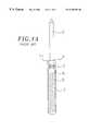
- FIG. 4is a cross-sectional view of the probe of the present invention with the open end of the barrel contacting the crimping surface prior to crimping.
- FIG. 5is a cross-sectional view of the probe of the present invention with the plunger compressed against the barrel for crimping the barrel open end.
- FIG. 6is a cross-sectional view of the probe of the present invention with the plunger fully biased from the barrel by the spring.
- FIG. 7is a cross-sectional view of the barrel of the present invention having longitudinal slits formed on the barrel open end prior to crimping.
- FIG. 8Ais a cross-sectional view of a crimped barrel of the present invention having slits.
- FIG. 8Bis a bottom view of the barrel shown in FIG. 8 A.
- FIG. 9is a cross-sectional view of a test socket section housing probes of an embodiment present invention.
- FIG. 10is a cross-sectional view of a test socket section housing probes of another embodiment of the present invention.
- FIG. 11is a cross-sectional view of a test socket section housing probes of a further embodiment of the present invention.
- FIG. 12is an exploded cross-sectional view of a barrel consisting of a hollow portion and a tip and flange portion.
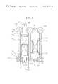
- FIG. 13is a cross-sectional view of a test socket housing probes of yet a further embodiment of the present invention.
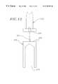
- FIG. 14is a cross-sectional view of a test socket housing probes of another embodiment of the present invention.
- a probe 10 of the present inventionconsists of a plunger 12 , a barrel 18 and a spring 16 .
- the barrelincludes an open end 20 .
- a contact tip 22extends from the end of the barrel opposite the barrel open end.
- a flange 24extends radially outward from the barrel typically at a location near the tip 22 .
- the barrelis made from brass and is gold plated, however, other electrically conductive materials can also be used.
- the plungeralso consists of a contact tip 26 .
- a flange 28also extends radially from a location typically at the base of the contact tip.
- the outer surface diameter 30 of the flange formed on the plungeris the same or similar as the outer surface diameter 32 of the flange formed on the barrel.
- the flangesare preferably annular.
- the plungerhas a stem 34 that extends axially in a direction opposite the plunger contact tip.
- An enlarged cylindrical surface 36is formed at the end of the stem defining a bearing.
- the bearing 36has a diameter slightly smaller than the inner surface diameter of the barrel.
- the bearingis preferably solid, but can also be hollow.
- the plungeris preferably made from BeCu and is also gold plated.
- a crimping surface 38is formed between the plunger flange and bearing.
- the crimping surfaceis used to crimp or otherwise bend inward the open end 20 of the barrel, thereby reducing the diameter of the open end.
- the crimping surfacedoes not extend to the perimeter of the plunger flange.
- the distance between the outer edge 40 of the crimping surface and the central axis 42 of the plungershould be at least equal and preferably greater than the inner radius 43 of the barrel. Preferably, such distance should be at least as long as the outer radius 44 of the barrel.
- the crimping surfacemay be annular, i.e., it may span entirely around the plunger. Alternatively, the crimping surface may span only a portion of the plunger circumference. In such case, multiple crimping surfaces may be formed around the plunger.
- the crimping surfaceis a frusto-conical surface that surrounds the stem. In another embodiment, the crimping surface is a section of a frusto conical surface (not shown).
- the crimping surface 38may be “U” shaped in cross-section for crimping the barrel end by causing it to curl onto itself as shown in FIG. 3 .
- a spring 16 having an inner diameter 46 greater than the barrel outer surface diameter 45 but not greater than the outer surface diameters 30 , 32 of the flangesis fitted over the barrel and the plunger between the flanges.
- the spring outer diameter 50is also not greater than the outer surface diameters 30 , 32 of the flanges.
- the springis preferably made of 302 stainless steel but can be made from other materials.
- the spring inner radiusshould be longer than the distance 52 between the plunger central axis 42 and the edge 40 of the crimping surface.
- the springis fitted over the barrel and rests against the barrel flange 24 .
- the springis fitted over the plunger bearing and stem and rests on the plunger flange 28 .
- the plunger bearingis then slid into the barrel such that the spring 16 is sandwiched between the barrel flange 24 and the plunger flange 28 .
- the barrel and plungerare moved toward each other such that the open end 20 of the barrel is engaged by the crimping surface 38 (FIG. 4 ).
- the edges 56 of the barrel open endare forced to bend or crimp radially inward by the crimping surface 38 (FIG. 5 ). Once the end of the barrel is crimped, it provides a barrier for retaining the bearing 36 within the barrel 18 as the plunger is biased by the spring from the barrel.
- the crimping surfaceis a frusto-conical surface (see FIGS. 2, 4 and 5 )
- the frusto-conical crimping surfaceprovides a radially inward force on the open end of the barrel as the barrel and plunger are compressed toward each other. The movement of the plunger toward the barrel is stopped when the bearing contacts the base surface 51 of the barrel.
- the combined length 58 of the stem and bearing as measured from the base of the stem beginning at the intersection between the stem and the crimping surfacecan be used to control the amount of crimping of the barrel end. For example, the shorter the combined length, the more crimping that will occur, i.e., a longer portion of the barrel end will be bent inwards.
- the length of the bent portion of the barrel endcan be controlled so as to not impinge on the stem.
- the assembly of the probeis simplified and the time of assembly is reduced since separate tools are not required for compressing the spring nor are separate tools required for crimping the barrel end.
- the crimping surfacedoes not span entirely around the plunger, the crimping surface will only crimp a portion of the barrel end.
- opposite sections of the barrelshould be crimped for retaining the bearing. This is achieved by having crimping surfaces extending opposite each other on the plunger.
- longitudinal slits 60may be formed along the barrel extending to the barrel end 20 as shown in FIG. 7 .
- Two or more slits equidistantly spacedare preferred.
- the slitsdivide the barrel open end into sections 62 and also facilitate the radially inward crimping of the cylindrical barrel open end surface as shown in FIG. 8 A.
- the sections 62 of the barrel end between the slitscan been bent toward each other, thereby narrowing the diameter of the barrel end 20 to a dimension smaller than the diameter of the bearing and thus provide a barrier for retaining the bearing within the barrel.
- These sectionsmay also be crimped as shown in FIGS. 8A and 8B.
- the barrel sections 62are pre-bent inward and/or their ends are pre-bent (i.e., pre-crimped) inward prior to engagement with the bearing. At least one of the sections and preferably all of the sections 62 of the barrel open end defined between the slits are pre-bent inward and/or pre-crimped as shown in FIGS. 8A and 8B.
- the barrel end sections between the slitscan flex. To assemble the probe, the bearing is pushed through the pre-bent and/or pre-crimped open end flexing the pre-bent and/or pre-crimped sections outward.
- the pre-bent and/or pre-crimped end sectionsflex back inward to their original pre-bent and/or pre-crimped position so that the pre-bent and/or pre-crimped end section(s) provides a barrier for retaining the bearing in the barrel.
- the plunger bearingis “snapped” into position inside the barrel.
- the barrel or plunger of the probemay each comprise multiple portions.
- the tip and flange of a barrelmay form one portion 200 while the barrel hollow section may form a second portion 202 (FIG. 12 ).
- the barrel hollow portionmay have a stud 204 extending from its end 208 opposite its open end 210 .
- the tip and flange portionmay have an axial opening 206 formed along the central axis of the flange and tip beginning at the flange and continuing into the tip.
- the stud 204is fitted into the opening 206 .
- the studmay be threaded to the opening or it may be press fitted into the opening, or the tip and flange portion may be crimped after the stud is fitted into the opening causing the inner surface of the opening 206 to lock on the stud.
- Other methods of connecting the portionsmay also be used which do not incorporate the use of a stud protruding through the barrel hollow portion or an opening in the flange and tip portion.
- a multiple portion barrel or plungerallows for the spring to be fitted over the barrel and plunger after the barrel end is crimped.
- the bearing of the plungermay be fitted into the barrel hollow portion through the hollow portion open end. The hollow portion open end is then crimped. A spring is then placed over the barrel hollow portion and is pushed against the flange of the plunger. The barrel tip and flange portion is then attached to the barrel hollow portion.
- a two portion plungermay be used where the plunger tip and flange form the first portion and the stem and bearing form the second portion. In such case, after the barrel open end is crimped retaining the plunger bearing, the spring is fitted over the plunger and barrel and is pushed against the barrel flange. The plunger tip and flange portion is then attached to the bearing and stem portion. Consequently, with these embodiments, the spring does not have to be compressed to expose the barrel open end to allow for crimping.
- the spring length 67 when compressedmay be longer than the length of the barrel as measured from the barrel flange surface 64 that supports the spring to the barrel open end.
- the uncrimped length 66 of the barrelmay be shorter than the length of the spring solid height 67 (FIG. 5 ).
- the fully compressed spring lengthmust be shorter than the length of the barrel to accommodate the plunger bearing(s).
- a shorter barrel lengthcan be used for a given spring length. As such, a shorter probe may be used having a shorter electrical interconnect without decreasing the spring length.
- the springis external to the interconnect, for a given spring height, the spring is more voluminous then an internal spring because it has a larger spring diameter and therefore a longer wire length.
- a longer springmay be used further increasing the spring volume and thus, the spring operating life without decreasing the spring compliance.
- moving a flange closer to its respective tipallows the length of the probe to be shortened without decreasing the spring length and compliance.
- the probeis biased laterally, i.e., that a bending force is applied to the probe attempting to bend the probe along its length.
- thisis accomplished by using a spring whose ends are not squared off such that the length 67 of the spring along one side of the barrel is longer than the length 69 of the spring along an opposite side of the barrel (FIG. 5 ). This is achieved by using a spring which begins and ends at the same side of the barrel.
- the force applied on the plunger by the springis greater on one side of the barrel (i.e., the side where the spring is longer) causing the plunger to extend along an axis skewed from the central of the barrel causing the bearing to maintain contact with the inner surface of the barrel.
- An exemplary probe of the present inventionhas a length 68 when fully biased by the spring of about 0.13 inch as measured from the plunger tip to the barrel tip (FIG. 6 ).
- the length of the exemplary probe when filly compressedis 0.1 inch.
- the exemplary probehas a travel or compliance of about 0.030 inch between the barrel and plunger with a spring force of about 1 ounce at about 0.020 inch travel.
- the probesare typically fitted in cavities 100 defined in sockets (or test plates) 102 (FIG. 9 ). These cavities have a diameter 104 to accommodate the probes with external springs. At an end face 106 of the socket, each cavity narrows to an opening 108 to allow for penetration by the probe tip. The narrowing of the cavities define shoulders 110 inside the cavities. Once the probes are inserted into the cavities their plunger flanges 28 engage the cavity shoulders 110 while their plunger tips 26 protrudes beyond the socket through openings 108 .
- a cover plate 112 plate having openings 114 in the same pattern as the openings 108 on the test socketis mated to the test socket such that the barrel tips 22 of the probe protrude through the openings 114 of the cover plate.
- the openings formed on the cover platehave a diameter larger than the diameter of the tips but smaller than the outer diameter of the flanges.
- the cover plateengages the barrel flanges 24 when the probes are extended. Consequently, the sockets with cover plate may serve to limit the extension of the probes.
- the probesmay also be mounted with their barrel tips 22 penetrating the socket openings 108 and their plunger tips 26 penetrating the cover plate openings 114 .
- the probes of the present inventiondo not have their barrel ends 20 crimped.
- each plungeris placed in a socket cavity 100 .
- a spring 16is then inserted over the plunger followed by a barrel which is pushed into the cavity to externally engage the plunger.
- the cover plate 112is then mated to the socket.
- the shoulders 110 formed in the cavities and the cover plate 112serve to keep the probe together.
- a probe of this embodimentdoes not require a separate bearing surface. Rather, the stem 34 can act as the bearing surface for bearing against the barrel inner walls (FIG. 10 ). With this embodiment, the diameter of the stem is slightly smaller than the inner diameter of the barrel.
- the probeconsists of a spring and two separate sections 120 , 122 each having a tip 124 and a flange 126 (FIG. 11 ).
- a contact component 128preferably having a semi-cylindrical portion 129 , extends from each probe section opposite the tip 124 .
- Each semi-cylindrical contact portionhas a semi-cylindrical surface 130 and a flat surface 132 .
- the first section 120is placed in the socket cavity such that its tip 124 protrudes through the cavity opening 108 .
- the spring 16is then inserted over the contact component and rests against the flange 126 .
- the second section 122is then inserted into the cavity with its contact component first such that the flat surface 132 of the second section contact component semi-cylindrical portion mates with the flat surface 132 of the first section contact component semi-cylindrical portion.
- the springis sandwiched between the two flanges.
- the contact component of each sectionmay be cylindrical, or the contact component of the first section may be cylindrical, while the contact component of a second section may be flat.
- the contact components of the two sections forming a probeshould maintain contact with each other so as to provide an electrical path between the two sections thus forming an electrical interconnect between the two sections. It is advantageous to form each probe using identical probe sections so as to simplify and reduce costs of probe manufacturing.
- the contact surfaces of the two componentsshould be complementary although not necessarily flat.
- the contact platei.e., the circuit board
- the contact platewhich is coupled to the test equipment 117 may be used to cover the cavities 100 .
- the contact platehas contact points 115 arranged in a pattern to come in contact with the probe section, plunger or barrel tips such as the tips 224 shown in FIG. 13 .
- the circuit board to be testedmay be used to close off the cavities 100 such that the contact points on the circuit board to be tested come in contact with the probe tips.
- the socketmay only have cylindrical cavities 300 as shown in FIG. 14 .
- the circuit board to be tested 302is mated to one side of the socket with its contact points 304 making contact with the probe tips 324 .
- the contact plate 113 coupled to the test equipment 117is mated to the opposite side of the socket whereby the circuit board and contact plate restrain the probes within the cavities.
- all of the aforementioned probe embodimentsallow for an increase in the spring volume without decreasing the spring compliance, and also allow for a decrease in the electrical interconnect length without decreasing the probe spring volume.
Landscapes
- Physics & Mathematics (AREA)
- General Physics & Mathematics (AREA)
- Measuring Leads Or Probes (AREA)
- Ultra Sonic Daignosis Equipment (AREA)
- Measurement Of The Respiration, Hearing Ability, Form, And Blood Characteristics Of Living Organisms (AREA)
- Testing Or Measuring Of Semiconductors Or The Like (AREA)
- Geophysics And Detection Of Objects (AREA)
- Springs (AREA)
- Cable Accessories (AREA)
- Testing Of Individual Semiconductor Devices (AREA)
Abstract
Description
Claims (20)
Priority Applications (18)
| Application Number | Priority Date | Filing Date | Title |
|---|---|---|---|
| US09/253,320US6396293B1 (en) | 1999-02-18 | 1999-02-18 | Self-closing spring probe |
| GB0021622AGB2351398B (en) | 1999-02-18 | 1999-03-16 | Spring probe |
| GB0021623AGB2351399B (en) | 1999-02-18 | 1999-03-16 | Spring probe assemblies |
| GB9905858AGB2347023B (en) | 1999-02-18 | 1999-03-16 | Spring probe |
| GB0021621AGB2356744B (en) | 1999-02-18 | 1999-03-16 | Spring probe |
| TW088105387ATW528871B (en) | 1999-02-18 | 1999-04-03 | Spring probe |
| DE69930717TDE69930717T2 (en) | 1999-02-18 | 1999-04-13 | spring sensor |
| EP99302847AEP1037055B1 (en) | 1999-02-18 | 1999-04-13 | Spring probe |
| EP04078167AEP1510827B1 (en) | 1999-02-18 | 1999-04-13 | Spring probe |
| AT04078167TATE370419T1 (en) | 1999-02-18 | 1999-04-13 | SPRING SENSOR |
| DE69936893TDE69936893T2 (en) | 1999-02-18 | 1999-04-13 | spring sensor |
| AT99302847TATE322691T1 (en) | 1999-02-18 | 1999-04-13 | SPRING SENSOR |
| JP15944299AJP3210645B2 (en) | 1999-02-18 | 1999-06-07 | Spring probe, spring probe assembly and method of assembling them |
| US09/614,422US6462567B1 (en) | 1999-02-18 | 2000-07-12 | Self-retained spring probe |
| HK01101340.4AHK1030455B (en) | 1999-02-18 | 2001-02-23 | Spring probe |
| HK01104425.6AHK1033976B (en) | 1999-02-18 | 2001-06-27 | Spring probe |
| HK01104426.5AHK1033977B (en) | 1999-02-18 | 2001-06-27 | Spring probe assemblies |
| HK01105237.1AHK1035030B (en) | 1999-02-18 | 2001-07-27 | Spring probe |
Applications Claiming Priority (1)
| Application Number | Priority Date | Filing Date | Title |
|---|---|---|---|
| US09/253,320US6396293B1 (en) | 1999-02-18 | 1999-02-18 | Self-closing spring probe |
Related Child Applications (1)
| Application Number | Title | Priority Date | Filing Date |
|---|---|---|---|
| US09/614,422Continuation-In-PartUS6462567B1 (en) | 1999-02-18 | 2000-07-12 | Self-retained spring probe |
Publications (1)
| Publication Number | Publication Date |
|---|---|
| US6396293B1true US6396293B1 (en) | 2002-05-28 |
Family
ID=22959787
Family Applications (1)
| Application Number | Title | Priority Date | Filing Date |
|---|---|---|---|
| US09/253,320Expired - LifetimeUS6396293B1 (en) | 1999-02-18 | 1999-02-18 | Self-closing spring probe |
Country Status (7)
| Country | Link |
|---|---|
| US (1) | US6396293B1 (en) |
| EP (2) | EP1037055B1 (en) |
| JP (1) | JP3210645B2 (en) |
| AT (2) | ATE322691T1 (en) |
| DE (2) | DE69936893T2 (en) |
| GB (1) | GB2347023B (en) |
| TW (1) | TW528871B (en) |
Cited By (43)
| Publication number | Priority date | Publication date | Assignee | Title |
|---|---|---|---|---|
| US6624645B2 (en)* | 1997-11-28 | 2003-09-23 | Fujitsu Limited | Semiconductor device testing method, using a spring-biased transformable conductive member electrode connection |
| US20040210140A1 (en)* | 2003-04-15 | 2004-10-21 | Omnisonics Medical Technologies, Inc. | Apparatus and method for preshaped ultrasonic probe |
| US20050146341A1 (en)* | 2002-03-05 | 2005-07-07 | Rika Electronics International, Inc | Apparatus for interfacing electronic packages and test equipment |
| US20050280433A1 (en)* | 2004-06-16 | 2005-12-22 | Nelson Larre H | Electrical test probes, methods of making, and methods of using |
| US20060073710A1 (en)* | 2004-10-06 | 2006-04-06 | Hwang Dong W | Contact for electronic devices |
| US20060220666A1 (en)* | 2000-06-16 | 2006-10-05 | Nhk Spring Co. Ltd. | Microcontactor probe assembly |
| US20060279301A1 (en)* | 2005-06-10 | 2006-12-14 | Valts Treibergs | Electrical contact probe with compliant internal interconnect |
| US7154286B1 (en)* | 2005-06-30 | 2006-12-26 | Interconnect Devices, Inc. | Dual tapered spring probe |
| US20070128906A1 (en)* | 2004-02-04 | 2007-06-07 | Nhk Spring Co., Ltd. | Needle-like member, conductive contact, and conductive contact unit |
| US20070284444A1 (en)* | 2006-06-12 | 2007-12-13 | Hellstrom Sven A | Mobile radio terminal having a multiple form factor memory card reader |
| US20080143367A1 (en)* | 2006-12-14 | 2008-06-19 | Scott Chabineau-Lovgren | Compliant electrical contact having maximized the internal spring volume |
| US20080278187A1 (en)* | 2007-05-07 | 2008-11-13 | Hongfei Yan | Test pin, method of manufacturing same, and system containing same |
| US7494468B2 (en) | 1999-10-05 | 2009-02-24 | Omnisonics Medical Technologies, Inc. | Ultrasonic medical device operating in a transverse mode |
| US7503895B2 (en) | 1999-10-05 | 2009-03-17 | Omnisonics Medical Technologies, Inc. | Ultrasonic device for tissue ablation and sheath for use therewith |
| US20090075529A1 (en)* | 2007-09-18 | 2009-03-19 | Johnston Charles J | Spring contact assembly |
| US20090278699A1 (en)* | 2008-05-12 | 2009-11-12 | John Vander Horst | Recreational vehicle holding tank sensor probe |
| US7677901B1 (en) | 2008-12-26 | 2010-03-16 | Yamaichi Electronics Co., Ltd. | Electric connecting apparatus for semiconductor devices and contact used therefor |
| US20100120299A1 (en)* | 2008-11-07 | 2010-05-13 | Kabushiki Kaisha Nihon Micronics | Contact and electrical connecting apparatus |
| US20100123476A1 (en)* | 2007-04-27 | 2010-05-20 | Nhk Spring Co., Ltd. | Conductive contact |
| US20100159753A1 (en)* | 2008-09-30 | 2010-06-24 | Hon Hai Precision Industry Co., Ltd. | Electrical contact having stamped contact pins movably assembled within enclosure member thereof |
| US7794414B2 (en) | 2004-02-09 | 2010-09-14 | Emigrant Bank, N.A. | Apparatus and method for an ultrasonic medical device operating in torsional and transverse modes |
| US20100231251A1 (en)* | 2009-03-10 | 2010-09-16 | Nelson John E | Electrically Conductive Pins For Microcircuit Tester |
| US20100271061A1 (en)* | 2009-04-27 | 2010-10-28 | Tsugio Yamamoto | Contact probe and socket |
| WO2012033802A3 (en)* | 2010-09-07 | 2012-05-18 | Johnstech International Corporation | Electrically conductive pins for microcircuit tester |
| CN102466740A (en)* | 2010-11-12 | 2012-05-23 | 金英杰 | Semiconductor Kelvin test probe |
| TWI426274B (en)* | 2010-06-30 | 2014-02-11 | Leeno Ind Inc | Probe |
| US20140091824A1 (en)* | 2012-09-28 | 2014-04-03 | Evan M. Fledell | Mechanism for facilitating a dynamic electro-mechanical interconnect having a cavity for embedding electrical components and isolating electrical paths |
| US8721372B2 (en) | 2010-02-05 | 2014-05-13 | Kabushiki Kaisha Nihon Micronics | Contact and electrical connecting apparatus |
| US8723540B2 (en) | 2011-01-17 | 2014-05-13 | Yokowo Co., Ltd. | Contact probe and socket |
| US8790359B2 (en) | 1999-10-05 | 2014-07-29 | Cybersonics, Inc. | Medical systems and related methods |
| US20140340106A1 (en)* | 2013-04-18 | 2014-11-20 | Isc Co., Ltd. | Probe member for pogo pin |
| TWI463141B (en)* | 2010-11-17 | 2014-12-01 | Nhk Spring Co Ltd | Contact probe and probe unit |
| US9007082B2 (en) | 2010-09-07 | 2015-04-14 | Johnstech International Corporation | Electrically conductive pins for microcircuit tester |
| US9297832B2 (en) | 2010-03-10 | 2016-03-29 | Johnstech International Corporation | Electrically conductive pins for microcircuit tester |
| WO2016128226A1 (en)* | 2015-02-12 | 2016-08-18 | Ptr Messtechnik Gmbh & Co. Kommanditgesellschaft | Method for assembling a component which has a sleeve, a piston with a piston head, and a spring, and component |
| US9726693B2 (en) | 2013-04-18 | 2017-08-08 | Isc Co., Ltd. | Probe member for pogo pin |
| US10411386B2 (en) | 2014-08-08 | 2019-09-10 | Nhk Spring Co., Ltd. | Connection terminal |
| KR20210029667A (en)* | 2019-09-06 | 2021-03-16 | 야마이치 일렉트로닉스 컴퍼니 리미티드 | Contact probe and inspecting socket including the same |
| US10976346B2 (en) | 2016-02-29 | 2021-04-13 | Yokowo Co., Ltd. | Socket |
| CN112740049A (en)* | 2018-09-26 | 2021-04-30 | 恩普乐股份有限公司 | Contact pin and socket |
| US20220137093A1 (en)* | 2018-12-03 | 2022-05-05 | Enplas Corporation | Contact pin and socket |
| WO2023049433A1 (en)* | 2021-09-27 | 2023-03-30 | Smiths Interconnect Americas, Inc. | Test socket and probe with stepped collar for semiconductor integrated circuits |
| USD1090440S1 (en) | 2023-01-12 | 2025-08-26 | Johnstech International Corporation | Spring probe contact assembly |
Families Citing this family (25)
| Publication number | Priority date | Publication date | Assignee | Title |
|---|---|---|---|---|
| JP3626609B2 (en) | 1998-10-30 | 2005-03-09 | 日本電気株式会社 | Multiprocessor system |
| JP4450397B2 (en)* | 1999-06-03 | 2010-04-14 | 有限会社清田製作所 | Double-end sliding contact probe |
| JP4521106B2 (en)* | 2000-09-28 | 2010-08-11 | 日本発條株式会社 | Conductive contact with movable guide plate |
| JP2002159913A (en)* | 2000-11-22 | 2002-06-04 | Shin Etsu Polymer Co Ltd | Vibrator with connector and its connecting structure |
| JP3767810B2 (en)* | 2001-04-27 | 2006-04-19 | 株式会社ヨコオ | Spring connector |
| JP2002350463A (en)* | 2001-05-23 | 2002-12-04 | Sanyu Kogyo Kk | Contact probe |
| KR100840834B1 (en)* | 2002-06-05 | 2008-06-23 | 이노우에 쇼지 가부시키가이샤 | Inspection jig of printed wiring board |
| KR100608232B1 (en)* | 2004-05-17 | 2006-08-03 | 리노공업주식회사 | Large Current Probe |
| KR100769891B1 (en)* | 2007-01-25 | 2007-10-24 | 리노공업주식회사 | Inspection probe and inspection socket using the same |
| WO2010016608A1 (en)* | 2008-08-08 | 2010-02-11 | 日本発條株式会社 | Electric contact member and contact probe |
| JP2012112709A (en)* | 2010-11-22 | 2012-06-14 | Unitechno Inc | Kelvin contact probe and kelvin inspection jig having the same |
| JP5097968B1 (en)* | 2011-08-02 | 2012-12-12 | 株式会社クローバーテクノロジー | Anisotropic conductive member |
| JP6009544B2 (en)* | 2012-04-17 | 2016-10-19 | ユニテクノ株式会社 | Kelvin contact probe and kelvin inspection jig provided with the same |
| JP2015004614A (en)* | 2013-06-21 | 2015-01-08 | 株式会社ミタカ | Contact probe |
| KR101591013B1 (en)* | 2014-09-29 | 2016-02-03 | (주) 네스텍코리아 | Self-Combined Prove Pin |
| KR101785591B1 (en)* | 2015-09-24 | 2017-10-17 | (주)엠투엔 | Interconnect structure and probe card having the same |
| KR101785605B1 (en)* | 2015-09-24 | 2017-10-17 | (주)엠투엔 | Interconnect structure and probe card having the same |
| JP6556612B2 (en)* | 2015-12-04 | 2019-08-07 | ルネサスエレクトロニクス株式会社 | Manufacturing method of semiconductor device |
| HUP1700051A2 (en) | 2017-02-02 | 2018-08-28 | Equip Test Kft | Contact device and headunit, and method of contact device and headunit production |
| JP6892277B2 (en)* | 2017-02-10 | 2021-06-23 | 株式会社日本マイクロニクス | Probes and electrical connections |
| JP6889067B2 (en)* | 2017-08-24 | 2021-06-18 | 株式会社日本マイクロニクス | Electrical connection device |
| JP6969929B2 (en)* | 2017-08-24 | 2021-11-24 | 株式会社日本マイクロニクス | Probe and its manufacturing method |
| JP6837513B2 (en)* | 2019-05-07 | 2021-03-03 | 株式会社ヨコオ | socket |
| WO2021065702A1 (en)* | 2019-10-04 | 2021-04-08 | 株式会社村田製作所 | Probe |
| DE102021120146A1 (en) | 2021-08-03 | 2023-02-09 | F I X T E S T Prüfmittelbau GmbH | contact pin |
Citations (16)
| Publication number | Priority date | Publication date | Assignee | Title |
|---|---|---|---|---|
| GB1324053A (en) | 1971-09-09 | 1973-07-18 | Carr V | Electrical contact probe |
| US3754731A (en)* | 1972-01-18 | 1973-08-28 | Halkey Roberts Corp | Inflation manifold valve and flange assembly |
| FR2224757A1 (en) | 1973-04-03 | 1974-10-31 | Cit Alcatel | Probe for printed circuit boards - mounted on subsidiary board in desired spatial arrangement for testing |
| US4438397A (en)* | 1979-12-26 | 1984-03-20 | Teradyne, Inc. | Test pin |
| JPS6212875A (en) | 1985-07-10 | 1987-01-21 | Mitsubishi Electric Corp | Test equipment for digital protective relay devices |
| US4701700A (en) | 1985-12-02 | 1987-10-20 | Jenkins Jack E | Captivated, pre-loaded spring means for vacuum displaced circuit board testing |
| US4740746A (en) | 1984-11-13 | 1988-04-26 | Tektronix, Inc. | Controlled impedance microcircuit probe |
| US4897043A (en)* | 1986-06-23 | 1990-01-30 | Feinmetall Gmbh | Resilient contact pin |
| US4904213A (en) | 1989-04-06 | 1990-02-27 | Motorola, Inc. | Low impedance electric connector |
| US4935695A (en) | 1988-07-13 | 1990-06-19 | Hewlett-Packard Company | Board alignment system |
| JPH04270967A (en) | 1990-06-11 | 1992-09-28 | Internatl Standard Electric Corp | Contact device |
| US5174763A (en) | 1990-06-11 | 1992-12-29 | Itt Corporation | Contact assembly |
| EP0616394A1 (en) | 1993-03-16 | 1994-09-21 | Hewlett-Packard Company | Method and system for producing electrically interconnected circuits |
| US5410260A (en) | 1992-11-09 | 1995-04-25 | Nhk Spring Co., Ltd. | Coil spring-pressed needle contact probe |
| US5746606A (en)* | 1996-09-30 | 1998-05-05 | Hughes Electronics | Spring loaded contact device and rotary connector |
| US6104205A (en)* | 1998-02-26 | 2000-08-15 | Interconnect Devices, Inc. | Probe with tab retainer |
Family Cites Families (2)
| Publication number | Priority date | Publication date | Assignee | Title |
|---|---|---|---|---|
| US5227718A (en)* | 1992-03-10 | 1993-07-13 | Virginia Panel Corporation | Double-headed spring contact probe assembly |
| ATE176966T1 (en)* | 1997-02-04 | 1999-03-15 | Durtal Sa | SPRING CONTACT ELEMENT |
- 1999
- 1999-02-18USUS09/253,320patent/US6396293B1/ennot_activeExpired - Lifetime
- 1999-03-16GBGB9905858Apatent/GB2347023B/ennot_activeExpired - Lifetime
- 1999-04-03TWTW088105387Apatent/TW528871B/ennot_activeIP Right Cessation
- 1999-04-13EPEP99302847Apatent/EP1037055B1/ennot_activeExpired - Lifetime
- 1999-04-13ATAT99302847Tpatent/ATE322691T1/ennot_activeIP Right Cessation
- 1999-04-13ATAT04078167Tpatent/ATE370419T1/ennot_activeIP Right Cessation
- 1999-04-13DEDE69936893Tpatent/DE69936893T2/ennot_activeExpired - Lifetime
- 1999-04-13EPEP04078167Apatent/EP1510827B1/ennot_activeExpired - Lifetime
- 1999-04-13DEDE69930717Tpatent/DE69930717T2/ennot_activeExpired - Lifetime
- 1999-06-07JPJP15944299Apatent/JP3210645B2/ennot_activeExpired - Lifetime
Patent Citations (16)
| Publication number | Priority date | Publication date | Assignee | Title |
|---|---|---|---|---|
| GB1324053A (en) | 1971-09-09 | 1973-07-18 | Carr V | Electrical contact probe |
| US3754731A (en)* | 1972-01-18 | 1973-08-28 | Halkey Roberts Corp | Inflation manifold valve and flange assembly |
| FR2224757A1 (en) | 1973-04-03 | 1974-10-31 | Cit Alcatel | Probe for printed circuit boards - mounted on subsidiary board in desired spatial arrangement for testing |
| US4438397A (en)* | 1979-12-26 | 1984-03-20 | Teradyne, Inc. | Test pin |
| US4740746A (en) | 1984-11-13 | 1988-04-26 | Tektronix, Inc. | Controlled impedance microcircuit probe |
| JPS6212875A (en) | 1985-07-10 | 1987-01-21 | Mitsubishi Electric Corp | Test equipment for digital protective relay devices |
| US4701700A (en) | 1985-12-02 | 1987-10-20 | Jenkins Jack E | Captivated, pre-loaded spring means for vacuum displaced circuit board testing |
| US4897043A (en)* | 1986-06-23 | 1990-01-30 | Feinmetall Gmbh | Resilient contact pin |
| US4935695A (en) | 1988-07-13 | 1990-06-19 | Hewlett-Packard Company | Board alignment system |
| US4904213A (en) | 1989-04-06 | 1990-02-27 | Motorola, Inc. | Low impedance electric connector |
| JPH04270967A (en) | 1990-06-11 | 1992-09-28 | Internatl Standard Electric Corp | Contact device |
| US5174763A (en) | 1990-06-11 | 1992-12-29 | Itt Corporation | Contact assembly |
| US5410260A (en) | 1992-11-09 | 1995-04-25 | Nhk Spring Co., Ltd. | Coil spring-pressed needle contact probe |
| EP0616394A1 (en) | 1993-03-16 | 1994-09-21 | Hewlett-Packard Company | Method and system for producing electrically interconnected circuits |
| US5746606A (en)* | 1996-09-30 | 1998-05-05 | Hughes Electronics | Spring loaded contact device and rotary connector |
| US6104205A (en)* | 1998-02-26 | 2000-08-15 | Interconnect Devices, Inc. | Probe with tab retainer |
Non-Patent Citations (2)
| Title |
|---|
| Udall, Gordon F., Specifying test fixtures for Automated Test Equipment, Instruments & Control Systems, pp. 63-66, vol. 55 (1982) Oct., No. 10, Radnor, Pennsylvania, USA. |
| Visual Inspection of Oztek .5mm Probe, Everett Charles Technologies Contact Products Division, Jun. 21, 2000 (1 page). |
Cited By (75)
| Publication number | Priority date | Publication date | Assignee | Title |
|---|---|---|---|---|
| US6624645B2 (en)* | 1997-11-28 | 2003-09-23 | Fujitsu Limited | Semiconductor device testing method, using a spring-biased transformable conductive member electrode connection |
| US7494468B2 (en) | 1999-10-05 | 2009-02-24 | Omnisonics Medical Technologies, Inc. | Ultrasonic medical device operating in a transverse mode |
| US8790359B2 (en) | 1999-10-05 | 2014-07-29 | Cybersonics, Inc. | Medical systems and related methods |
| US7503895B2 (en) | 1999-10-05 | 2009-03-17 | Omnisonics Medical Technologies, Inc. | Ultrasonic device for tissue ablation and sheath for use therewith |
| US20060220666A1 (en)* | 2000-06-16 | 2006-10-05 | Nhk Spring Co. Ltd. | Microcontactor probe assembly |
| US7459922B2 (en) | 2000-06-16 | 2008-12-02 | Nhk Spring Co. Ltd. | Microcontactor probe assembly having a plunger and electric probe unit using the same |
| US20050146341A1 (en)* | 2002-03-05 | 2005-07-07 | Rika Electronics International, Inc | Apparatus for interfacing electronic packages and test equipment |
| US7362114B2 (en) | 2002-03-05 | 2008-04-22 | Rika Electronics International, Inc. | Apparatus for interfacing electronic packages and test equipment |
| US20040210140A1 (en)* | 2003-04-15 | 2004-10-21 | Omnisonics Medical Technologies, Inc. | Apparatus and method for preshaped ultrasonic probe |
| US20070128906A1 (en)* | 2004-02-04 | 2007-06-07 | Nhk Spring Co., Ltd. | Needle-like member, conductive contact, and conductive contact unit |
| CN100492020C (en)* | 2004-02-04 | 2009-05-27 | 日本发条株式会社 | Pin member, conductive contact, and conductive contact unit |
| US7815438B2 (en)* | 2004-02-04 | 2010-10-19 | Nhk Spring Co., Ltd. | Needle-like member, conductive contact, and conductive contact unit |
| US7794414B2 (en) | 2004-02-09 | 2010-09-14 | Emigrant Bank, N.A. | Apparatus and method for an ultrasonic medical device operating in torsional and transverse modes |
| US20050280433A1 (en)* | 2004-06-16 | 2005-12-22 | Nelson Larre H | Electrical test probes, methods of making, and methods of using |
| WO2006007440A1 (en)* | 2004-06-16 | 2006-01-19 | Rika Denshi America, Inc. | Electrical test probes, methods of making, and methods of using |
| US7315176B2 (en) | 2004-06-16 | 2008-01-01 | Rika Denshi America, Inc. | Electrical test probes, methods of making, and methods of using |
| US20060073710A1 (en)* | 2004-10-06 | 2006-04-06 | Hwang Dong W | Contact for electronic devices |
| US7025602B1 (en) | 2004-10-06 | 2006-04-11 | Plastronics Socket Partners, L.P. | Contact for electronic devices |
| US7256593B2 (en)* | 2005-06-10 | 2007-08-14 | Delaware Capital Formation, Inc. | Electrical contact probe with compliant internal interconnect |
| CN101501509B (en)* | 2005-06-10 | 2013-08-14 | 特拉华资本组成公司 | Electrical contact probe with compliant internal interconnect |
| US20060279301A1 (en)* | 2005-06-10 | 2006-12-14 | Valts Treibergs | Electrical contact probe with compliant internal interconnect |
| US20070001695A1 (en)* | 2005-06-30 | 2007-01-04 | Marx Donald A | Dual tapered spring probe |
| US7154286B1 (en)* | 2005-06-30 | 2006-12-26 | Interconnect Devices, Inc. | Dual tapered spring probe |
| US7392946B2 (en) | 2006-06-12 | 2008-07-01 | Sony Ericsson Mobile Communications Ab | Mobile radio terminal having a multiple form factor memory card reader |
| US20070284444A1 (en)* | 2006-06-12 | 2007-12-13 | Hellstrom Sven A | Mobile radio terminal having a multiple form factor memory card reader |
| US20080143367A1 (en)* | 2006-12-14 | 2008-06-19 | Scott Chabineau-Lovgren | Compliant electrical contact having maximized the internal spring volume |
| US20100123476A1 (en)* | 2007-04-27 | 2010-05-20 | Nhk Spring Co., Ltd. | Conductive contact |
| US7521949B2 (en)* | 2007-05-07 | 2009-04-21 | Intel Corporation | Test pin, method of manufacturing same, and system containing same |
| US20080278187A1 (en)* | 2007-05-07 | 2008-11-13 | Hongfei Yan | Test pin, method of manufacturing same, and system containing same |
| US20110039457A1 (en)* | 2007-09-18 | 2011-02-17 | Delaware Capital Formation, Inc. | Spring contact assembly |
| US7862391B2 (en)* | 2007-09-18 | 2011-01-04 | Delaware Capital Formation, Inc. | Spring contact assembly |
| US8523579B2 (en) | 2007-09-18 | 2013-09-03 | Delaware Capital Formation, Inc. | Spring contact assembly |
| US8231416B2 (en)* | 2007-09-18 | 2012-07-31 | Delaware Capital Formation, Inc. | Spring contact assembly |
| US20090075529A1 (en)* | 2007-09-18 | 2009-03-19 | Johnston Charles J | Spring contact assembly |
| KR101145283B1 (en)* | 2007-09-18 | 2012-05-14 | 델라웨어 캐피탈 포메이션, 인코포레이티드 | Spring contact assembly |
| US8410948B2 (en)* | 2008-05-12 | 2013-04-02 | John Vander Horst | Recreational vehicle holding tank sensor probe |
| US20090278699A1 (en)* | 2008-05-12 | 2009-11-12 | John Vander Horst | Recreational vehicle holding tank sensor probe |
| US7841866B2 (en)* | 2008-09-30 | 2010-11-30 | Hon Hai Precision Ind. Co. Ltd. | Electrical contact having stamped contact pins movably assembled within enclosure member thereof |
| US20100159753A1 (en)* | 2008-09-30 | 2010-06-24 | Hon Hai Precision Industry Co., Ltd. | Electrical contact having stamped contact pins movably assembled within enclosure member thereof |
| US7946855B2 (en)* | 2008-11-07 | 2011-05-24 | Kabushiki Kaisha Nihon Micronics | Contact and electrical connecting apparatus |
| US20100120299A1 (en)* | 2008-11-07 | 2010-05-13 | Kabushiki Kaisha Nihon Micronics | Contact and electrical connecting apparatus |
| US7677901B1 (en) | 2008-12-26 | 2010-03-16 | Yamaichi Electronics Co., Ltd. | Electric connecting apparatus for semiconductor devices and contact used therefor |
| US20100231251A1 (en)* | 2009-03-10 | 2010-09-16 | Nelson John E | Electrically Conductive Pins For Microcircuit Tester |
| US8536889B2 (en) | 2009-03-10 | 2013-09-17 | Johnstech International Corporation | Electrically conductive pins for microcircuit tester |
| US20100271061A1 (en)* | 2009-04-27 | 2010-10-28 | Tsugio Yamamoto | Contact probe and socket |
| US8519727B2 (en)* | 2009-04-27 | 2013-08-27 | Yokowo Co., Ltd. | Contact probe and socket |
| US8721372B2 (en) | 2010-02-05 | 2014-05-13 | Kabushiki Kaisha Nihon Micronics | Contact and electrical connecting apparatus |
| US10302675B2 (en) | 2010-03-10 | 2019-05-28 | Johnstech International Corporation | Electrically conductive pins microcircuit tester |
| US10073117B2 (en) | 2010-03-10 | 2018-09-11 | Johnstech International Corporation | Resilient interposer with electrically conductive slide-by pins as part of a microcircuit tester |
| US9678106B2 (en) | 2010-03-10 | 2017-06-13 | Johnstech International Corporation | Electrically conductive pins for microcircuit tester |
| US9297832B2 (en) | 2010-03-10 | 2016-03-29 | Johnstech International Corporation | Electrically conductive pins for microcircuit tester |
| US9128120B2 (en) | 2010-06-30 | 2015-09-08 | Leeno Industrial Inc. | Probe |
| TWI426274B (en)* | 2010-06-30 | 2014-02-11 | Leeno Ind Inc | Probe |
| US9007082B2 (en) | 2010-09-07 | 2015-04-14 | Johnstech International Corporation | Electrically conductive pins for microcircuit tester |
| US10877090B2 (en) | 2010-09-07 | 2020-12-29 | Johnstech International Corporation | Electrically conductive pins for microcircuit tester |
| WO2012033802A3 (en)* | 2010-09-07 | 2012-05-18 | Johnstech International Corporation | Electrically conductive pins for microcircuit tester |
| CN102466740A (en)* | 2010-11-12 | 2012-05-23 | 金英杰 | Semiconductor Kelvin test probe |
| TWI463141B (en)* | 2010-11-17 | 2014-12-01 | Nhk Spring Co Ltd | Contact probe and probe unit |
| US8723540B2 (en) | 2011-01-17 | 2014-05-13 | Yokowo Co., Ltd. | Contact probe and socket |
| US9128121B2 (en)* | 2012-09-28 | 2015-09-08 | Intel Corporation | Mechanism for facilitating a dynamic electro-mechanical interconnect having a cavity for embedding electrical components and isolating electrical paths |
| US20140091824A1 (en)* | 2012-09-28 | 2014-04-03 | Evan M. Fledell | Mechanism for facilitating a dynamic electro-mechanical interconnect having a cavity for embedding electrical components and isolating electrical paths |
| US20140340106A1 (en)* | 2013-04-18 | 2014-11-20 | Isc Co., Ltd. | Probe member for pogo pin |
| US9310395B2 (en)* | 2013-04-18 | 2016-04-12 | Isc Co., Ltd. | Probe member for pogo pin |
| US9726693B2 (en) | 2013-04-18 | 2017-08-08 | Isc Co., Ltd. | Probe member for pogo pin |
| US10411386B2 (en) | 2014-08-08 | 2019-09-10 | Nhk Spring Co., Ltd. | Connection terminal |
| WO2016128226A1 (en)* | 2015-02-12 | 2016-08-18 | Ptr Messtechnik Gmbh & Co. Kommanditgesellschaft | Method for assembling a component which has a sleeve, a piston with a piston head, and a spring, and component |
| US10976346B2 (en) | 2016-02-29 | 2021-04-13 | Yokowo Co., Ltd. | Socket |
| CN112740049A (en)* | 2018-09-26 | 2021-04-30 | 恩普乐股份有限公司 | Contact pin and socket |
| US11506684B2 (en) | 2018-09-26 | 2022-11-22 | Enplas Corporation | Contact pin and socket |
| CN112740049B (en)* | 2018-09-26 | 2023-12-08 | 恩普乐股份有限公司 | Contact pin and socket |
| US20220137093A1 (en)* | 2018-12-03 | 2022-05-05 | Enplas Corporation | Contact pin and socket |
| US11821917B2 (en)* | 2018-12-03 | 2023-11-21 | Enplas Corporation | Contact pin and socket |
| KR20210029667A (en)* | 2019-09-06 | 2021-03-16 | 야마이치 일렉트로닉스 컴퍼니 리미티드 | Contact probe and inspecting socket including the same |
| WO2023049433A1 (en)* | 2021-09-27 | 2023-03-30 | Smiths Interconnect Americas, Inc. | Test socket and probe with stepped collar for semiconductor integrated circuits |
| USD1090440S1 (en) | 2023-01-12 | 2025-08-26 | Johnstech International Corporation | Spring probe contact assembly |
Also Published As
| Publication number | Publication date |
|---|---|
| JP3210645B2 (en) | 2001-09-17 |
| DE69936893D1 (en) | 2007-09-27 |
| HK1033977A1 (en) | 2001-10-05 |
| HK1030455A1 (en) | 2001-05-04 |
| EP1510827A1 (en) | 2005-03-02 |
| EP1037055A2 (en) | 2000-09-20 |
| TW528871B (en) | 2003-04-21 |
| HK1033976A1 (en) | 2001-10-05 |
| ATE322691T1 (en) | 2006-04-15 |
| GB9905858D0 (en) | 1999-05-05 |
| GB2347023B (en) | 2001-07-25 |
| EP1037055B1 (en) | 2006-04-05 |
| ATE370419T1 (en) | 2007-09-15 |
| DE69936893T2 (en) | 2008-05-15 |
| GB2347023A (en) | 2000-08-23 |
| DE69930717T2 (en) | 2007-01-25 |
| DE69930717D1 (en) | 2006-05-18 |
| JP2000241447A (en) | 2000-09-08 |
| EP1037055A3 (en) | 2001-03-28 |
| EP1510827B1 (en) | 2007-08-15 |
| HK1035030A1 (en) | 2001-11-09 |
Similar Documents
| Publication | Publication Date | Title |
|---|---|---|
| US6396293B1 (en) | Self-closing spring probe | |
| US6462567B1 (en) | Self-retained spring probe | |
| US7256593B2 (en) | Electrical contact probe with compliant internal interconnect | |
| US7862391B2 (en) | Spring contact assembly | |
| US20190067859A1 (en) | Spring connector | |
| JP6231994B2 (en) | Electrical connector having an insulating member | |
| EP2836847B1 (en) | Test probe assembly and related methods | |
| US20080143367A1 (en) | Compliant electrical contact having maximized the internal spring volume | |
| US5801544A (en) | Spring probe and method for biasing | |
| US20100007365A1 (en) | Socket for double ended probe, double ended probe, and probe unit | |
| US8710856B2 (en) | Terminal for flat test probe | |
| US20100244875A1 (en) | Scrub inducing compliant electrical contact | |
| TW201043968A (en) | Swaging process for improved compliant contact electrical test performance | |
| GB2351398A (en) | Spring probe for testing | |
| US6271672B1 (en) | Biased BGA contactor probe tip | |
| HK1054984B (en) | Self-retained spring probe |
Legal Events
| Date | Code | Title | Description |
|---|---|---|---|
| AS | Assignment | Owner name:DELAWARE CAPITAL FORMATION, INC., DELAWARE Free format text:ASSIGNMENT OF ASSIGNORS INTEREST;ASSIGNORS:VINTHER, GORDON, A.;CHABINEAU, SCOTT D.;JOHNSTON, CHARLES J.;REEL/FRAME:009797/0211;SIGNING DATES FROM 19990215 TO 19990216 | |
| STCF | Information on status: patent grant | Free format text:PATENTED CASE | |
| FPAY | Fee payment | Year of fee payment:4 | |
| FPAY | Fee payment | Year of fee payment:8 | |
| FPAY | Fee payment | Year of fee payment:12 | |
| AS | Assignment | Owner name:SILICON VALLEY BANK, AS ADMINISTRATIVE AGENT, CALI Free format text:SECURITY AGREEMENT;ASSIGNORS:LTX-CREDENCE CORPORATION;EVERETT CHARLES TECHNOLOGIES LLC;REEL/FRAME:032086/0476 Effective date:20131127 | |
| AS | Assignment | Owner name:XCERRA CORPORATION, MASSACHUSETTS Free format text:CHANGE OF NAME;ASSIGNOR:LTX-CREDENCE CORPORATION;REEL/FRAME:033032/0768 Effective date:20140520 | |
| AS | Assignment | Owner name:LTX-CREDENCE CORPORATION, MASSACHUSETTS Free format text:ASSIGNMENT OF ASSIGNORS INTEREST;ASSIGNOR:DELAWARE CAPITAL FORMATION, INC.;REEL/FRAME:033091/0639 Effective date:20131122 | |
| AS | Assignment | Owner name:SILICON VALLEY BANK, AS ADMINISTRATIVE AGENT, CALI Free format text:SECURITY AGREEMENT;ASSIGNORS:XCERRA CORPORATION;EVERETT CHARLES TECHNOLOGIES LLC;REEL/FRAME:034660/0188 Effective date:20141215 Owner name:EVERETT CHARLES TECHNOLOGIES LLC, MASSACHUSETTS Free format text:RELEASE OF SECURITY INTEREST IN UNITED STATES PATENTS;ASSIGNOR:SILICON VALLEY BANK, AS ADMINISTRATIVE AGENT;REEL/FRAME:034660/0394 Effective date:20141215 Owner name:XCERRA CORPORATION, MASSACHUSETTS Free format text:RELEASE OF SECURITY INTEREST IN UNITED STATES PATENTS;ASSIGNOR:SILICON VALLEY BANK, AS ADMINISTRATIVE AGENT;REEL/FRAME:034660/0394 Effective date:20141215 | |
| AS | Assignment | Owner name:SILICON VALLEY BANK, AS ADMINISTRATIVE AGENT, CALI Free format text:CORRECTIVE ASSIGNMENT TO CORRECT THE INCORRECT PATENT NUMBER 7261561 AND REPLACE WITH PATENT NUMBER 7231561 PREVIOUSLY RECORDED ON REEL 034660 FRAME 0188. ASSIGNOR(S) HEREBY CONFIRMS THE SECURITY AGREEMENT;ASSIGNORS:XCERRA CORPORATION;EVERETT CHARLES TECHNOLOGIES LLC;REEL/FRAME:037824/0372 Effective date:20141215 | |
| AS | Assignment | Owner name:DEUTSCHE BANK AG NEW YORK BRANCH, AS COLLATERAL AGENT, NEW YORK Free format text:PATENT SECURITY AGREEMENT;ASSIGNOR:XCERRA CORPORATION;REEL/FRAME:047185/0624 Effective date:20181001 Owner name:DEUTSCHE BANK AG NEW YORK BRANCH, AS COLLATERAL AG Free format text:PATENT SECURITY AGREEMENT;ASSIGNOR:XCERRA CORPORATION;REEL/FRAME:047185/0624 Effective date:20181001 | |
| AS | Assignment | Owner name:DEUTSCHE BANK AG NEW YORK BRANCH, AS COLLATERAL AGENT, NEW YORK Free format text:CORRECTIVE ASSIGNMENT TO CORRECT THE INCORRECT STATEMENT THAT THIS DOCUMENT SERVES AS AN OATH/DECLARATION PREVIOUSLY RECORDED ON REEL 047185 FRAME 0628. ASSIGNOR(S) HEREBY CONFIRMS THE PATENT SECURITY AGREEMENT;ASSIGNOR:XCERRA CORPORATION;REEL/FRAME:047675/0354 Effective date:20181001 Owner name:DEUTSCHE BANK AG NEW YORK BRANCH, AS COLLATERAL AG Free format text:CORRECTIVE ASSIGNMENT TO CORRECT THE INCORRECT STATEMENT THAT THIS DOCUMENT SERVES AS AN OATH/DECLARATION PREVIOUSLY RECORDED ON REEL 047185 FRAME 0628. ASSIGNOR(S) HEREBY CONFIRMS THE PATENT SECURITY AGREEMENT;ASSIGNOR:XCERRA CORPORATION;REEL/FRAME:047675/0354 Effective date:20181001 | |
| AS | Assignment | Owner name:XCERRA CORPORATION, MASSACHUSETTS Free format text:TERMINATION AND RELEASE OF SECURITY INTEREST IN PATENTS, RECORDED AT REEL 047185, FRAME 0624;ASSIGNOR:DEUTSCHE BANK AG NEW YORK BRANCH, AS AGENT;REEL/FRAME:066762/0811 Effective date:20240209 |