US6396025B1 - Powder feed nozzle for laser welding - Google Patents
Powder feed nozzle for laser weldingDownload PDFInfo
- Publication number
- US6396025B1 US6396025B1US09/366,792US36679299AUS6396025B1US 6396025 B1US6396025 B1US 6396025B1US 36679299 AUS36679299 AUS 36679299AUS 6396025 B1US6396025 B1US 6396025B1
- Authority
- US
- United States
- Prior art keywords
- powder
- focus
- channel
- nozzle
- discharge outlet
- Prior art date
- Legal status (The legal status is an assumption and is not a legal conclusion. Google has not performed a legal analysis and makes no representation as to the accuracy of the status listed.)
- Expired - Lifetime
Links
Images


Classifications
- B—PERFORMING OPERATIONS; TRANSPORTING
- B23—MACHINE TOOLS; METAL-WORKING NOT OTHERWISE PROVIDED FOR
- B23K—SOLDERING OR UNSOLDERING; WELDING; CLADDING OR PLATING BY SOLDERING OR WELDING; CUTTING BY APPLYING HEAT LOCALLY, e.g. FLAME CUTTING; WORKING BY LASER BEAM
- B23K26/00—Working by laser beam, e.g. welding, cutting or boring
- B23K26/14—Working by laser beam, e.g. welding, cutting or boring using a fluid stream, e.g. a jet of gas, in conjunction with the laser beam; Nozzles therefor
- B23K26/144—Working by laser beam, e.g. welding, cutting or boring using a fluid stream, e.g. a jet of gas, in conjunction with the laser beam; Nozzles therefor the fluid stream containing particles, e.g. powder
Definitions
- the present inventionrelates to a nozzle for direct metal deposition and other laser welding applications.
- the present inventionrelates to a powder feed nozzle for use for direct metal deposition and other laser welding applications.
- Laser welding applicationsuse high powered lasers or other high energy sources to melt deposited material for welding.
- Laser weldingis used to fabricate components by a direct metal deposition technique to form various shapes and forms.
- the deposited structuremay be machined to a desired finish to complete the fabrication process.
- Powderis dispersed from feed nozzles to a molten puddle or pool formed by the laser.
- Catchmentis a term which refers to the amount of powder deposited to the molten pool relative to the amount of powder discharged or dispersed from the nozzle. If the dispersement profile of powder discharged from the nozzle is greater than the area of the molten pool or puddle, then catchment is poor since powder is dispersed to areas surrounding the molten pool in addition to the molten pool. Powder that is deposited outside of the molten pool can have certain deleterious effect on the metallurgical qualities and performance of the resulting structure as well as increased costs.
- molten and other material from the workpiececan spatter to the nozzle which can clog the nozzle.
- Residue spattered to the nozzlecan alter the profile of powder dispersed from the nozzle or completely clog the nozzle. Reflected laser beams from the melt puddle can also sinter powder or melt the nozzle tip.
- the present inventionrelates to a powder feed nozzle for laser welding applications including a multiple outlet nozzle tip for focusing a discharged powder stream.
- the multiple outlet nozzle tipdisperses multiple outlet streams and includes a powder discharge outlet and at least one focus gas discharge outlet, radially spaced from the powder discharge outlet, for dispersing a powder stream and a gas stream.
- Powderflows from a powder source through a powder channel to the powder discharge outlet for dispersement.
- Focus gasflows through a focus gas channel angled relative to the powder channel to discharge a focus gas stream.
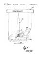
- FIG. 1is a illustration of a laser welding process.
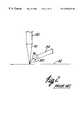
- FIG. 2is a detailed schematic illustration of deposition of powder to a workpiece.
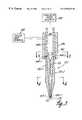
- FIG. 3is a cross-sectional view of an embodiment of a powder feed nozzle of the present invention for laser welding applications.
- FIG. 4is a cross-sectional view as taken along lines 4 — 4 of FIG. 3 .
- FIG. 5is a cross-sectional view as taken along lines 5 — 5 of FIG. 3 .
- FIG. 6illustrates deposition of a tight focused powder stream to a workpiece.
- FIG. 7schematically illustrates deposition of a tight focused power stream to a workpiece.
- FIG. 8is a detailed cross-sectional view of an end portion of the nozzle tip illustrated in FIG. 3 .
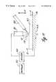
- FIG. 9is an exploded view of the embodiment of the nozzle of FIG. 3 .
- FIG. 10illustrates a deposited structure formed by an omni-directional deposition process.
- FIG. 11illustrates deposition of layer B- 1 to a workpiece along a first leg.
- FIG. 12illustrates deposition of layer B- 2 to a workpiece along a second leg.
- FIG. 13illustrates deposition of layer B- 3 to a workpiece along a third leg.
- FIG. 14is a cross-sectional view of an alternate embodiment of a powder feed nozzle of the present invention including a cooling collar.
- FIG. 15is a cross-sectional view of an embodiment of a cooling collar for a powder feed nozzle.
- FIG. 16is a cross-sectional view as taken along line 16 — 16 of FIG. 15 .
- FIG. 17is an exploded view of the powder feed nozzle illustrated in FIG. 14 .
- FIG. 1schematically illustrates a laser welding operation for direct metal deposition for fabricating components of various shapes and forms.
- Laser weldinguses a laser 80 , such a CO 2 laser to melt a powder, such as a titanium powder, deposited to a workpiece 82 from a powder source through a nozzle 84 . Multiple layers of powder are deposited to workpiece 82 to form a fabricated component according to direct metal deposition techniques.
- workpiece 82is supported on a welding table 86 .
- welding table 86movable supports the workpiece 82 as illustrated by arrow 88 relative to laser 80 and nozzle 84 for forming complex three dimensional components.
- laser 80 and nozzle 84can be movably supported relative to the workpiece 82 or fixed welding table 86 .
- the nozzle 84 and laser 80are indexed or raised to adjust the elevation of the nozzle 84 relative to the surface of the workpiece elevated by the deposited layer. Welding operation can be controlled by controller 90 as illustrated in FIG. 1 .
- Laser beam 92 from laser 80forms a molten pool or envelope 94 on the workpiece 82 .
- Nozzle 84disperses a powder stream 96 to deposit a powder envelope 98 to the workpiece 82 .
- powder envelope 98is deposited to the molten pool or puddle 94 to melt the powder.
- the powder envelope 98is targeted to optimize the amount of dispersed powder caught or contained in the molten pool 94 .
- powderis dispersed from nozzle 84 and is deposited to the workpiece under the influence of gravity.
- dispersed powdercan be caught outside of the molten pool or puddle resulting in poor catchment of the powder in the molten pool or puddle 94 .
- laser beam 92 or spatter from the molten poolcan reflect back to the nozzle as illustrated by arrow 100 .
- Reflected spattercan plug powder discharge openings altering the geometry and profile of the dispersed powder stream (and envelope 98 ).
- the reflected laser beam 92can melt the nozzle and powder also plugging powder discharge openings.
- FIGS. 3-5illustrate an embodiment of a multiple outlet nozzle tip 120 for depositing powder to a molten spot 94 .
- Nozzle tip 120includes a powder discharge outlet 122 and focus gas discharge outlet 124 radially spaced from the powder discharge outlet 122 .
- Powder discharge outlet 122is in fluid communication with a powder feed channel 126 extending through the nozzle tip 120 and coupleable to a powder source 128 for discharging a powder stream from the nozzle tip.
- Focus gas discharge outlet 124is in fluid communication with a focus gas channel 130 coupleable to a focus gas source 132 .
- Focus gas channel 130is angled relative to powder feed channel 126 to discharge a focus gas stream directed toward the powder stream to focus the powder stream for controlling the dispersed profile of the powder stream for optimum catchment.
- the focus gas stream 133 dischargedprovides a tight powder stream 134 with increased velocity for depositing powder to the molten pool 94 .
- the tight focused powder stream 134blocks or decouples the nozzle tip 120 from back reflections of the laser and provides a more dense moving mass to intercept spatter in flight toward the nozzle tip 120 .
- the focus gas stream 133 and powder stream 134opaque the nozzle from laser reflections.
- nozzle tip 120includes a plurality of focus gas channels 130 - 1 to 130 -n and outlets 124 - 1 to 124 -n concentrically arranged about the powder feed channel 126 and outlet 122 to focus or pinch discharged powder to provide a tight dispersement profile of the powder for increased catchment.
- Powder debris from the powder stream or weld spattercan be reflected from the workpiece or sprayed back to the nozzle after being discharged. Reflected powder can clog the powder discharge outlet changing the profile of the discharge outlet and the discharged powder stream.
- the plurality of spaced focus gas outlets 124 - 1 to 124 -nprovides multiple spaced smaller openings in contrast to a single opening to limit the effects of power debris reflected to the nozzle. Thus, if one of the openings 124 - 1 to 124 -n becomes clogged, other openings remain functional to focus the powder stream.
- the focus gasis an inert gas.
- Helium gasis used as a focus gas for a welding process using an argon gas welding chamber. During welding operations, the high energy of a CO 2 laser beam would couple with and ionize the Argon, forming a plasma.
- the Helium focus gasdilutes the Argon gas at the high energy focal point of the laser to decouple or shield the laser energy from the Argon gas to limit ionization of the Argon gas at the high energy point of the welding operation.
- nozzle tip 120is coupled to nozzle base 136 having a powder supply line 138 and an annular focus gas chamber 140 .
- Powder supply line 138is coupled to powder source 128 so that powder flows from powder source 128 through supply line 138 .
- Powder supply line 138is in communication with powder channel 126 through a tapered smooth transition 142 connecting the larger diameter supply line 138 and smaller diameter channel 126 .
- the smooth transition 142reduces sharp edges between supply line 138 and channel 126 to avoid powder catching on sharp edges.
- Annular focus gas chamber 140surrounds the powder supply line 138 and is in communication with a plurality of inlets 144 - 1 to 144 -n to channels 130 - 1 to 130 -n. Focus gas chamber 140 is filled with focus gas for discharge through discharge outlets 124 - 1 to 124 -n.
- powder channel 126has a constant cross--sectional profile along an extent of the nozzle tip 120 to the discharge opening 122 .
- the constant cross-sectional profileprovides a relatively laminar flow of powder from an inlet (at smooth transition 142 in FIG. 3) through the powder channel 126 to the discharge opening 122 to discharge a relatively laminar flow powder stream from the nozzle tip.
- powder flow through channel 126is with an inert gas assist, such as an Argon or Helium gas assist.
- focus gas channels 130 - 1 to 130 -nare radially spaced from powder channel 126 and have a relatively constant flow diameter and profile from inlet 144 - 1 to 144 -n to outlets 124 - 1 to 124 -n to provide a laminar gas flow for a controlled focus gas stream.
- Focus channels 130 - 1 to 130 -nare angled ⁇ , as illustrated in FIG. 8, relative to powder channel 126 so that the gas stream discharged from outlets 124 - 1 to 124 -n is directed towards the discharged powder stream to pinch the powder stream to provide a tight powder stream with increased velocity so that the powder stream is caught in the molten pool 94 as illustrated in FIG. 6 .
- nozzle tip 120is removable coupled to nozzle base 136 .
- nozzle tip 120includes a stepped stem 150 having a stepped tip 152 , threaded outer collar 154 and smooth transition 142 .
- Supply line 138has an opened end 158 and annular chamber of nozzle base 136 includes an opened threaded end 160 .
- Stepped tip 152is press fit into opened end 158 to close powder supply line 138 and outer collar 154 is threaded to end 160 to removably connect annular chamber 140 and supply line 138 to nozzle tip.
- powder supply line 138 and annular chamber 140are fluidly coupled to powder feed channel 126 and focus gas channels 130 , respectively.
- the nozzle tip 120can be easily removed from the nozzle base 136 and replaced when powder and focus gas outlets 122 , 124 - 1 to 124 -n are clogged for continued use.
- a nozzle tip describedcan be constructed from a four-inch gas torch nozzle available from ESAB Welding and Cutting Products of Florence, S.C. 29501.
- Direct metal depositioncan be used to fabricate complex shapes.
- the present inventionrelates to an omni-directional deposition process for forming complex shapes, for example a “U” shaped element 161 as illustrated in FIG. 10 (or circular element (not shown)), without stopping or resetting the position or orientation of the nozzle outlet.
- “U” shaped elementincludes opposed legs 162 , 163 connect by transverse leg 164 .
- Legs of the “U” shaped elementare formed by omni-directional deposition or application of powder as illustrated by arrows 165 , 166 , 167 .
- FIGS. 11-13illustrate an omni-directional deposition process forming the “U” shaped element illustrated in FIG. 10, although it should be understood that application of omni-directional deposition is not limited to a “U” shaped element.
- workpieceis moved along an x-axis relative to laser and nozzle as illustrated by arrow 168 to deposit layer B- 1 along leg 162 .
- nozzleis positioned forward of a crown 170 of layer B- 1 during the deposition process along leg 162 .
- workpiecemoves transverse to leg 162 along a y-axis as illustrated by arrow 172 to deposit layer B- 2 along leg 164 .
- nozzleis laterally orientated relative to crown 170 .
- FIG. 11workpiece is moved along an x-axis relative to laser and nozzle as illustrated by arrow 168 to deposit layer B- 1 along leg 162 .
- nozzleis positioned forward of a crown 170 of layer B- 1 during the deposition process along leg 162 .
- workpiecemoves
- nozzleis positioned rearward of crown 170 .
- componentsare fabricated by an omni-directional deposition process where powder is deposited by a nozzle positioned in multiple orientations relative to the crown 170 (e.g. forward, rearward or lateral orientation relative to the crown 170 ). Successive layers (along the z-axis) are deposited via omni-directional deposition for fabricating complex components or a component having a single leg or orientation.
- the orientation of the nozzleis fixed relative to the laser so that nozzle outlet is orientated behind, rearward or lateral of the crown 170 as illustrated in FIGS. 11-13.
- the tight powder stream dispersed from the nozzlefacilitates deposition of powder regardless of the forward, rearward or lateral orientation of the nozzle relative to the crown 164 .
- movement omni-directional movement (in an x, y or x-y direction) of the nozzle and workpieceis implemented by actuator 172 under control of controller 174 configured for omni-directional movement of actuator 172 .
- Actuator 172can be a motor drive and can move the workpiece table 86 or nozzle 120 in an x, y, or x-y direction for complex welding operations.
- FIG. 14illustrates an embodiment of a nozzle tip 120 - 1 including a cooling chamber 180 , where similar numbers are used to identify similar parts of nozzle tip 120 - 1 .
- nozzle tipsupports a cooling collar 182 having cooling chamber 180 formed therein coupled to a fluid cooling source 184 , for example water. Cooling fluid is pumped from cooling fluid source 184 for circulation in cooling chamber 180 . Cooling fluid is continuously circulated through chamber 180 to reduce operating temperature of the nozzle positioned proximate to the focal point of laser 80 . Cooling fluid is exhausted from chamber 180 as illustrated by block 186 .
- FIGS. 15-16illustrate an embodiment of cooling collar 182 .
- cooling collar 182is formed of an annular member having a central opening 188 sized for placement about nozzle tip 120 - 1 and an annular channel 190 extending about central opening 188 .
- Opening 188extends between opposed first and second spaced ends 192 , 194 of collar 182 and is opened at opposed ends 192 , 194 for placement about nozzle tip 120 - 1 .
- Opening 188is internally threaded 196 for attachment to the nozzle tip 120 - 1 .
- Annular channel 190has an annular stepped opening 198 formed at the first end 192 .
- Hosing 200 for pumping fluid into and out of chamber 180is shown diagrammatically in FIG. 13 .
- Hosing 200is connected to rings 202 , 204 which are seated in the stepped opening 198 to connect chamber 180 (formed by annular channel 190 ) to cooling fluid source and to exhaust cooling fluid.
- cooling collar 182is positioned proximate to a first end of the nozzle tip 120 - 1 spaced from discharge outlets 122 , 124 .
- Nozzle tip 120 - 1is formed of a solid block having channels 126 , 130 formed (or bored) therethrough.
- the solid nozzle tip 120provides a continuous heat transfer path axially along the nozzle tip 120 (along the length of the powder channel 126 and focus gas channels 130 - 1 to 130 -n) to cool the discharge openings 122 , 124 - 1 to 124 -n and the nozzle tip facing the molten pool.
- a Helium focusing gas flowing in channels 130 - 1 to 130 - 2has a high heat capacity and also assists in the cooling of the nozzle.
- a solid interfaceseparates the spaced channels 126 , 130 - 1 to 130 -n to provide a thermally conductive path from the cooling collar 182 along the length of the channels 126 and 130 - 1 to 130 -n.
- the plurality of spaced focus gas outlets 124 - 1 to 124 -n shownprovides more surface area surrounding the discharge outlets for providing a conductive path surrounding each outlets 122 , 124 - 1 to 124 -n for maintaining the temperature of the outlets 122 and 124 - 1 to 124 -n.
- nozzle tip 120is formed of a single block of copper material with high thermal conductivity for optimum heat transfer.
- FIG. 17is an exploded view illustrating removable assembly of nozzle tip 120 - 1 to nozzle base 136 - 1 .
- a separate smooth transition section 208(formed separately from nozzle tip 120 - 1 ) is welded to an inner tube 206 forming powder supply line 138 and collar 182 is welded to outer tube 210 of nozzle base 136 - 1 .
- a stepped end 212 of nozzle tipextends through a compressible sealing ring 214 and is press fit into a bore 215 of smooth transition section 208 . Threaded portion 216 of stepped end 212 threadably engages threads 196 of collar 182 to removeably connect nozzle tip 120 - 1 to nozzle base and cooling collar 182 .
- threaded portion 216 and tip 217 of stepped end 212The extent between threaded portion 216 and tip 217 of stepped end 212 is sized so that when nozzle tip is threaded to collar 182 , tip 217 compresses against compressible sealing ring 214 to provide a fluid tight seal to separate powder from focus gas and fluidly connect powder supply line 138 and channel 126 .
- Threaded connection between threaded portion 216 and threads 196fluidly couples channels 130 - 1 to 130 -n of nozzle tip to outer tube 210 .
- the nozzle tip 120has a relatively flat end face 218 normal to the axis of channel 126 so that discharge openings are on the same plane and radially spaced for focusing the discharged powder into a tight powder stream to direct powder to molten pool 94 for increased catchment and decouple the nozzle from back reflections of the laser.
- the multiple outlet nozzledischarges a powder stream and a focus gas stream to focus and opaque the nozzle from laser reflections.
Landscapes
- Physics & Mathematics (AREA)
- Optics & Photonics (AREA)
- Engineering & Computer Science (AREA)
- Plasma & Fusion (AREA)
- Mechanical Engineering (AREA)
- Laser Beam Processing (AREA)
Abstract
Description
Claims (26)
Priority Applications (5)
| Application Number | Priority Date | Filing Date | Title |
|---|---|---|---|
| US09/366,792US6396025B1 (en) | 1999-07-01 | 1999-08-04 | Powder feed nozzle for laser welding |
| PCT/US2000/018092WO2001002129A2 (en) | 1999-07-01 | 2000-06-30 | Powder feed nozzle for laser welding |
| AU59042/00AAU5904200A (en) | 1999-07-01 | 2000-06-30 | Powder feed nozzle for laser welding |
| US10/113,861US6696664B2 (en) | 1999-07-01 | 2002-04-01 | Powder feed nozzle for laser welding |
| US10/746,727US6881919B2 (en) | 1999-07-01 | 2003-12-26 | Powder feed nozzle for laser welding |
Applications Claiming Priority (2)
| Application Number | Priority Date | Filing Date | Title |
|---|---|---|---|
| US14193699P | 1999-07-01 | 1999-07-01 | |
| US09/366,792US6396025B1 (en) | 1999-07-01 | 1999-08-04 | Powder feed nozzle for laser welding |
Related Child Applications (1)
| Application Number | Title | Priority Date | Filing Date |
|---|---|---|---|
| US10/113,861DivisionUS6696664B2 (en) | 1999-07-01 | 2002-04-01 | Powder feed nozzle for laser welding |
Publications (1)
| Publication Number | Publication Date |
|---|---|
| US6396025B1true US6396025B1 (en) | 2002-05-28 |
Family
ID=26839589
Family Applications (3)
| Application Number | Title | Priority Date | Filing Date |
|---|---|---|---|
| US09/366,792Expired - LifetimeUS6396025B1 (en) | 1999-07-01 | 1999-08-04 | Powder feed nozzle for laser welding |
| US10/113,861Expired - LifetimeUS6696664B2 (en) | 1999-07-01 | 2002-04-01 | Powder feed nozzle for laser welding |
| US10/746,727Expired - Fee RelatedUS6881919B2 (en) | 1999-07-01 | 2003-12-26 | Powder feed nozzle for laser welding |
Family Applications After (2)
| Application Number | Title | Priority Date | Filing Date |
|---|---|---|---|
| US10/113,861Expired - LifetimeUS6696664B2 (en) | 1999-07-01 | 2002-04-01 | Powder feed nozzle for laser welding |
| US10/746,727Expired - Fee RelatedUS6881919B2 (en) | 1999-07-01 | 2003-12-26 | Powder feed nozzle for laser welding |
Country Status (3)
| Country | Link |
|---|---|
| US (3) | US6396025B1 (en) |
| AU (1) | AU5904200A (en) |
| WO (1) | WO2001002129A2 (en) |
Cited By (19)
| Publication number | Priority date | Publication date | Assignee | Title |
|---|---|---|---|---|
| US20020020164A1 (en)* | 2000-07-26 | 2002-02-21 | Cleveland Bradley A. | Tubular body with deposited features and method of manufacture therefor |
| US6518541B1 (en)* | 1999-11-16 | 2003-02-11 | Joseph K. Kelly | Duty cycle stabilization in direct metal deposition (DMD) systems |
| WO2004011185A1 (en)* | 2002-07-26 | 2004-02-05 | Honeywell International Inc. | Powder feed splitter for hand-held laser powder fusion welding torch |
| US20050038551A1 (en)* | 2002-08-29 | 2005-02-17 | Jyoti Mazumder | Method of fabricating composite tooling using closed-loop direct-metal deposition |
| US20050099449A1 (en)* | 2003-11-07 | 2005-05-12 | Tim Frasure | Methods and structures for disassembling inkjet printhead components and control therefor |
| US20050131522A1 (en)* | 2003-12-10 | 2005-06-16 | Stinson Jonathan S. | Medical devices and methods of making the same |
| US6974207B2 (en) | 2002-11-19 | 2005-12-13 | Lexmark International, Inc. | Laser welding methods and structures and control therefor including welded inkjet printheads |
| US20080128053A1 (en)* | 2006-12-05 | 2008-06-05 | Noble Advanced Technologies | Method of manufacturing a welded metal panel having a high quality surface finish |
| US20080179300A1 (en)* | 2005-09-23 | 2008-07-31 | Fraunhofer Usa | Diamond hard coating of ferrous substrates |
| CN100408250C (en)* | 2005-11-25 | 2008-08-06 | 北京工业大学 | A side-axis powder feeding device and powder feeding method based on laser powder filling welding |
| US20090314136A1 (en)* | 2008-06-23 | 2009-12-24 | The Stanley Works | Method of manufacturing a blade |
| US20110300306A1 (en)* | 2009-12-04 | 2011-12-08 | The Regents Of The University Of Michigan | Coaxial laser assisted cold spray nozzle |
| US8769833B2 (en) | 2010-09-10 | 2014-07-08 | Stanley Black & Decker, Inc. | Utility knife blade |
| CN104694922A (en)* | 2015-03-30 | 2015-06-10 | 湖南大学 | Ring hole type laser coaxial powder feeding nozzle |
| US9095994B2 (en) | 2011-08-09 | 2015-08-04 | GM Global Technology Operations LLC | Method for applying variable magnetic properties to a induction heated tool face and manufacturing parts using the tool |
| US10119195B2 (en) | 2009-12-04 | 2018-11-06 | The Regents Of The University Of Michigan | Multichannel cold spray apparatus |
| WO2021052814A1 (en)* | 2019-09-16 | 2021-03-25 | Fraunhofer-Gesellschaft zur Förderung der angewandten Forschung e.V. | Stock feeding device |
| US11383316B2 (en)* | 2017-10-16 | 2022-07-12 | Karl F. HRANKA | Wire arc hybrid manufacturing |
| AU2018241250B2 (en)* | 2017-03-29 | 2024-04-11 | Laserbond Limited | Methods, systems and assemblies for laser deposition |
Families Citing this family (36)
| Publication number | Priority date | Publication date | Assignee | Title |
|---|---|---|---|---|
| US6593540B1 (en)* | 2002-02-08 | 2003-07-15 | Honeywell International, Inc. | Hand held powder-fed laser fusion welding torch |
| US20050056628A1 (en)* | 2003-09-16 | 2005-03-17 | Yiping Hu | Coaxial nozzle design for laser cladding/welding process |
| KR100738219B1 (en)* | 2003-12-23 | 2007-07-12 | 삼성에스디아이 주식회사 | Interlayer forming material for organic electroluminescent device and organic electroluminescent device using same |
| AT500561B1 (en)* | 2004-05-26 | 2006-12-15 | Miba Sinter Austria Gmbh | PROCESS FOR WELDING A SINTERED FORM BODY |
| EP1616655B1 (en)* | 2004-07-13 | 2006-11-08 | C.R.F. Società Consortile per Azioni | Method for laser welding of elements of sintered material |
| US7550693B2 (en)* | 2005-02-04 | 2009-06-23 | Honeywell International Inc. | Hand-held laser welding wand with improved optical assembly serviceability features |
| EP1928631A4 (en)* | 2005-08-23 | 2009-08-05 | Hardwear Pty Ltd | Powder delivery nozzle |
| FI119923B (en)* | 2005-09-08 | 2009-05-15 | Kemppi Oy | Method and apparatus for short arc welding |
| ES2278521B1 (en)* | 2005-10-10 | 2008-06-16 | Universidad De Vigo | Nodalized nozzle for injecting powder, particularly in powder metallurgy, comprises central body that projects dust of feeding tube settled on body, where moving crown is adjusted and positioned with respect to body |
| FR2893360A1 (en)* | 2005-11-15 | 2007-05-18 | Snecma Sa | METHOD FOR PRODUCING A SEALING LABYRINTH LECHET, THERMOMECHANICAL PART AND TURBOMACHINE COMPRISING SUCH A LECHET |
| US7358457B2 (en)* | 2006-02-22 | 2008-04-15 | General Electric Company | Nozzle for laser net shape manufacturing |
| GB0621184D0 (en)* | 2006-10-25 | 2006-12-06 | Rolls Royce Plc | Method for treating a component of a gas turbine engine |
| GB0701397D0 (en)* | 2007-01-25 | 2007-03-07 | Rolls Royce Plc | Apparatus and method for calibrating a laser deposition system |
| GB2449862B (en)* | 2007-06-05 | 2009-09-16 | Rolls Royce Plc | Method for producing abrasive tips for gas turbine blades |
| JP5061836B2 (en)* | 2007-10-10 | 2012-10-31 | 株式会社日立プラントテクノロジー | Impeller welding method and impeller |
| US8800480B2 (en) | 2007-10-10 | 2014-08-12 | Ronald Peter Whitfield | Laser cladding device with an improved nozzle |
| US8117985B2 (en)* | 2007-10-10 | 2012-02-21 | Ronald Peter Whitfield | Laser cladding device with an improved nozzle |
| US9352420B2 (en) | 2007-10-10 | 2016-05-31 | Ronald Peter Whitfield | Laser cladding device with an improved zozzle |
| DE202008002271U1 (en)* | 2008-02-16 | 2008-04-24 | Kimme, Thomas | Fabric feeding device for welding, sintering and alloying workpieces |
| US8704120B2 (en)* | 2008-07-03 | 2014-04-22 | Esab Ab | Device for handling powder for a welding apparatus |
| DE102008057309B3 (en)* | 2008-11-13 | 2009-12-03 | Trumpf Laser- Und Systemtechnik Gmbh | Determining misadjustment of powder supply nozzle, by which powder is guided as additives on workpiece, relative to laser beam, comprises constructing test structure on the workpiece in different directions by powder deposition welding |
| GB0822703D0 (en)* | 2008-12-15 | 2009-01-21 | Rolls Royce Plc | A component having an abrasive layer and a method of applying an abrasive layer on a component |
| US8829388B2 (en)* | 2011-07-29 | 2014-09-09 | Ipg Photonics Corporation | Method for contactless laser welding and apparatus |
| US10201877B2 (en)* | 2011-10-26 | 2019-02-12 | Titanova Inc | Puddle forming and shaping with primary and secondary lasers |
| US20140065320A1 (en)* | 2012-08-30 | 2014-03-06 | Dechao Lin | Hybrid coating systems and methods |
| CN103060801B (en)* | 2013-01-29 | 2014-11-05 | 西安交通大学 | Coaxial powder delivery nozzle applied to variable spot technique |
| US10384264B2 (en) | 2015-01-16 | 2019-08-20 | Rolls-Royce Corporation | Compact axially translational powder deposition head |
| JP2018528877A (en) | 2015-07-17 | 2018-10-04 | アプライド マテリアルズ インコーポレイテッドApplied Materials,Incorporated | Additive manufacturing with coolant system |
| JP2018531799A (en)* | 2015-10-30 | 2018-11-01 | ハイパーサーム インコーポレイテッド | Thermal conditioning device for laser machining head for water cooling of laser components |
| CN105170979A (en)* | 2015-11-03 | 2015-12-23 | 哈尔滨工业大学 | Side-shaft powder-feeding nozzle for laser additive manufacturing |
| EP3603853A4 (en)* | 2017-03-31 | 2020-12-23 | Nikon Corporation | Modeling system and modeling method |
| FR3081365B1 (en)* | 2018-05-28 | 2020-05-22 | Beam | METAL POWDER JET ANALYSIS SYSTEM AND METHOD |
| WO2019231966A1 (en) | 2018-06-01 | 2019-12-05 | Applied Materials, Inc. | Air knife for additive manufacturing |
| US11413817B2 (en) | 2019-09-26 | 2022-08-16 | Applied Materials, Inc. | Air knife inlet and exhaust for additive manufacturing |
| US11400649B2 (en) | 2019-09-26 | 2022-08-02 | Applied Materials, Inc. | Air knife assembly for additive manufacturing |
| US20220258201A1 (en)* | 2021-02-12 | 2022-08-18 | Johnson Matthey Public Limited Company | Powder spraying system, powder spraying nozzle and method |
Citations (46)
| Publication number | Priority date | Publication date | Assignee | Title |
|---|---|---|---|---|
| US3947653A (en) | 1973-10-24 | 1976-03-30 | Sirius Corporation | Method of spray coating using laser-energy beam |
| US3960422A (en) | 1974-08-05 | 1976-06-01 | Liconix | Process for manufacturing a helium metal vapor laser tube |
| US4300474A (en) | 1979-03-30 | 1981-11-17 | Rolls-Royce Limited | Apparatus for application of metallic coatings to metallic substrates |
| US4462511A (en) | 1980-09-15 | 1984-07-31 | Viking Injector Company | Dissolving and dispensing apparatus |
| US4482375A (en) | 1983-12-05 | 1984-11-13 | Mcdonnell Douglas Corporation | Laser melt spin atomized metal powder and process |
| US4575330A (en) | 1984-08-08 | 1986-03-11 | Uvp, Inc. | Apparatus for production of three-dimensional objects by stereolithography |
| US4627990A (en) | 1984-03-07 | 1986-12-09 | Honda Giken Kogyo Kabushiki Kaisha | Method of and apparatus for supplying powdery material |
| US4681258A (en) | 1983-04-25 | 1987-07-21 | National Research Development Corporation | Producing directed spray |
| US4724299A (en) | 1987-04-15 | 1988-02-09 | Quantum Laser Corporation | Laser spray nozzle and method |
| US4730093A (en) | 1984-10-01 | 1988-03-08 | General Electric Company | Method and apparatus for repairing metal in an article |
| US4743733A (en) | 1984-10-01 | 1988-05-10 | General Electric Company | Method and apparatus for repairing metal in an article |
| US4927992A (en) | 1987-03-04 | 1990-05-22 | Westinghouse Electric Corp. | Energy beam casting of metal articles |
| US4947463A (en) | 1988-02-24 | 1990-08-07 | Agency Of Industrial Science & Technology | Laser spraying process |
| US4958058A (en) | 1989-02-08 | 1990-09-18 | General Electric Company | Transverse flow laser spray nozzle |
| US5043548A (en) | 1989-02-08 | 1991-08-27 | General Electric Company | Axial flow laser plasma spraying |
| US5076869A (en) | 1986-10-17 | 1991-12-31 | Board Of Regents, The University Of Texas System | Multiple material systems for selective beam sintering |
| US5111021A (en) | 1990-10-16 | 1992-05-05 | Societe Nationale Industrielle Et Aerospatiale | Laser surface treatment nozzle with powder supply |
| US5121329A (en) | 1989-10-30 | 1992-06-09 | Stratasys, Inc. | Apparatus and method for creating three-dimensional objects |
| US5122632A (en) | 1989-10-20 | 1992-06-16 | Konrad Kinkelin | Device for laser plasma coating |
| US5126529A (en) | 1990-12-03 | 1992-06-30 | Weiss Lee E | Method and apparatus for fabrication of three-dimensional articles by thermal spray deposition |
| US5182430A (en) | 1990-10-10 | 1993-01-26 | Societe National D'etude Et De Construction De Moteurs D'aviation "S.N.E.C.M.A." | Powder supply device for the formation of coatings by laser beam treatment |
| US5208431A (en) | 1990-09-10 | 1993-05-04 | Agency Of Industrial Science & Technology | Method for producing object by laser spraying and apparatus for conducting the method |
| US5245155A (en) | 1992-03-06 | 1993-09-14 | General Electric Company | Single point powder feed nozzle for use in laser welding |
| US5252264A (en) | 1991-11-08 | 1993-10-12 | Dtm Corporation | Apparatus and method for producing parts with multi-directional powder delivery |
| US5303141A (en) | 1991-01-03 | 1994-04-12 | International Business Machines Corporation | Model generation system having closed-loop extrusion nozzle positioning |
| US5304771A (en) | 1992-02-18 | 1994-04-19 | D. A. Griffin Corporation | Apparatus for precisely metering powder for welding |
| US5321228A (en)* | 1991-06-24 | 1994-06-14 | Andreas Krause | Nozzle for the surface treatment of metal workpieces |
| US5321288A (en) | 1990-09-28 | 1994-06-14 | Texas Instruments Incorporated | Nonvolatile memory array in which each cell has a single floating gate having two tunnelling windows |
| US5359907A (en) | 1992-11-12 | 1994-11-01 | Horiba Instruments, Inc. | Method and apparatus for dry particle analysis |
| US5418350A (en) | 1992-01-07 | 1995-05-23 | Electricite De Strasbourg (S.A.) | Coaxial nozzle for surface treatment by laser irradiation, with supply of materials in powder form |
| US5477025A (en) | 1994-01-14 | 1995-12-19 | Quantum Laser Corporation | Laser nozzle |
| US5477026A (en) | 1994-01-27 | 1995-12-19 | Chromalloy Gas Turbine Corporation | Laser/powdered metal cladding nozzle |
| US5486676A (en) | 1994-11-14 | 1996-01-23 | General Electric Company | Coaxial single point powder feed nozzle |
| US5488216A (en) | 1993-08-30 | 1996-01-30 | Messer Griesheim Gmbh | Protective gas for the laser welding of aluminum |
| US5522555A (en) | 1994-03-01 | 1996-06-04 | Amherst Process Instruments, Inc. | Dry powder dispersion system |
| US5556560A (en) | 1992-03-31 | 1996-09-17 | Plasma Modules Oy | Welding assembly for feeding powdered filler material into a torch |
| US5579107A (en) | 1995-05-25 | 1996-11-26 | Horiba Instruments, Inc. | Method and apparatus for dry particle analysis |
| WO1997004914A1 (en) | 1995-07-28 | 1997-02-13 | Commonwealth Scientific And Industrial Research Organisation | Pulsed laser cladding arrangement |
| DE19533960A1 (en) | 1995-09-13 | 1997-03-20 | Fraunhofer Ges Forschung | Method and device for producing metallic workpieces |
| US5649277A (en) | 1993-06-09 | 1997-07-15 | Fraunhofer-Gesellschaft Zur Foerderung Der Angewandten Forschung E.V. | Process and apparatus for the free-forming manufacture of three dimensional components of predetermined shape |
| US5676866A (en) | 1994-01-01 | 1997-10-14 | Carl-Zeiss Stiftung | Apparatus for laser machining with a plurality of beams |
| US5717559A (en) | 1995-07-28 | 1998-02-10 | Nec Corporation | Input/output protection device for use in semiconductor device |
| US5732323A (en) | 1994-09-21 | 1998-03-24 | Aktiebolaget Electrolux | Method for fabricating dimensionally accurate pieces by laser sintering |
| US5738817A (en) | 1996-02-08 | 1998-04-14 | Rutgers, The State University | Solid freeform fabrication methods |
| US5745834A (en) | 1995-09-19 | 1998-04-28 | Rockwell International Corporation | Free form fabrication of metallic components |
| US5837960A (en) | 1995-08-14 | 1998-11-17 | The Regents Of The University Of California | Laser production of articles from powders |
Family Cites Families (4)
| Publication number | Priority date | Publication date | Assignee | Title |
|---|---|---|---|---|
| GB1111722A (en)* | 1965-12-13 | 1968-05-01 | Millard Fillmore Smith | Coating process and apparatus |
| GB9008703D0 (en)* | 1990-04-18 | 1990-06-13 | Alcan Int Ltd | Spray deposition of metals |
| JPH04337945A (en) | 1991-05-15 | 1992-11-25 | Nec Corp | Protocol composition/decomposition supporting device |
| US5717599A (en) | 1994-10-19 | 1998-02-10 | Bpm Technology, Inc. | Apparatus and method for dispensing build material to make a three-dimensional article |
- 1999
- 1999-08-04USUS09/366,792patent/US6396025B1/ennot_activeExpired - Lifetime
- 2000
- 2000-06-30AUAU59042/00Apatent/AU5904200A/ennot_activeAbandoned
- 2000-06-30WOPCT/US2000/018092patent/WO2001002129A2/enactiveApplication Filing
- 2002
- 2002-04-01USUS10/113,861patent/US6696664B2/ennot_activeExpired - Lifetime
- 2003
- 2003-12-26USUS10/746,727patent/US6881919B2/ennot_activeExpired - Fee Related
Patent Citations (47)
| Publication number | Priority date | Publication date | Assignee | Title |
|---|---|---|---|---|
| US3947653A (en) | 1973-10-24 | 1976-03-30 | Sirius Corporation | Method of spray coating using laser-energy beam |
| US3960422A (en) | 1974-08-05 | 1976-06-01 | Liconix | Process for manufacturing a helium metal vapor laser tube |
| US4300474A (en) | 1979-03-30 | 1981-11-17 | Rolls-Royce Limited | Apparatus for application of metallic coatings to metallic substrates |
| US4462511A (en) | 1980-09-15 | 1984-07-31 | Viking Injector Company | Dissolving and dispensing apparatus |
| US4681258A (en) | 1983-04-25 | 1987-07-21 | National Research Development Corporation | Producing directed spray |
| US4482375A (en) | 1983-12-05 | 1984-11-13 | Mcdonnell Douglas Corporation | Laser melt spin atomized metal powder and process |
| US4627990A (en) | 1984-03-07 | 1986-12-09 | Honda Giken Kogyo Kabushiki Kaisha | Method of and apparatus for supplying powdery material |
| US4575330A (en) | 1984-08-08 | 1986-03-11 | Uvp, Inc. | Apparatus for production of three-dimensional objects by stereolithography |
| US4575330B1 (en) | 1984-08-08 | 1989-12-19 | ||
| US4730093A (en) | 1984-10-01 | 1988-03-08 | General Electric Company | Method and apparatus for repairing metal in an article |
| US4743733A (en) | 1984-10-01 | 1988-05-10 | General Electric Company | Method and apparatus for repairing metal in an article |
| US5076869A (en) | 1986-10-17 | 1991-12-31 | Board Of Regents, The University Of Texas System | Multiple material systems for selective beam sintering |
| US4927992A (en) | 1987-03-04 | 1990-05-22 | Westinghouse Electric Corp. | Energy beam casting of metal articles |
| US4724299A (en) | 1987-04-15 | 1988-02-09 | Quantum Laser Corporation | Laser spray nozzle and method |
| US4947463A (en) | 1988-02-24 | 1990-08-07 | Agency Of Industrial Science & Technology | Laser spraying process |
| US4958058A (en) | 1989-02-08 | 1990-09-18 | General Electric Company | Transverse flow laser spray nozzle |
| US5043548A (en) | 1989-02-08 | 1991-08-27 | General Electric Company | Axial flow laser plasma spraying |
| US5122632A (en) | 1989-10-20 | 1992-06-16 | Konrad Kinkelin | Device for laser plasma coating |
| US5121329A (en) | 1989-10-30 | 1992-06-09 | Stratasys, Inc. | Apparatus and method for creating three-dimensional objects |
| US5208431A (en) | 1990-09-10 | 1993-05-04 | Agency Of Industrial Science & Technology | Method for producing object by laser spraying and apparatus for conducting the method |
| US5321288A (en) | 1990-09-28 | 1994-06-14 | Texas Instruments Incorporated | Nonvolatile memory array in which each cell has a single floating gate having two tunnelling windows |
| US5182430A (en) | 1990-10-10 | 1993-01-26 | Societe National D'etude Et De Construction De Moteurs D'aviation "S.N.E.C.M.A." | Powder supply device for the formation of coatings by laser beam treatment |
| US5111021A (en) | 1990-10-16 | 1992-05-05 | Societe Nationale Industrielle Et Aerospatiale | Laser surface treatment nozzle with powder supply |
| US5126529A (en) | 1990-12-03 | 1992-06-30 | Weiss Lee E | Method and apparatus for fabrication of three-dimensional articles by thermal spray deposition |
| US5303141A (en) | 1991-01-03 | 1994-04-12 | International Business Machines Corporation | Model generation system having closed-loop extrusion nozzle positioning |
| US5321228A (en)* | 1991-06-24 | 1994-06-14 | Andreas Krause | Nozzle for the surface treatment of metal workpieces |
| US5252264A (en) | 1991-11-08 | 1993-10-12 | Dtm Corporation | Apparatus and method for producing parts with multi-directional powder delivery |
| US5418350A (en) | 1992-01-07 | 1995-05-23 | Electricite De Strasbourg (S.A.) | Coaxial nozzle for surface treatment by laser irradiation, with supply of materials in powder form |
| US5304771A (en) | 1992-02-18 | 1994-04-19 | D. A. Griffin Corporation | Apparatus for precisely metering powder for welding |
| US5245155A (en) | 1992-03-06 | 1993-09-14 | General Electric Company | Single point powder feed nozzle for use in laser welding |
| US5556560A (en) | 1992-03-31 | 1996-09-17 | Plasma Modules Oy | Welding assembly for feeding powdered filler material into a torch |
| US5359907A (en) | 1992-11-12 | 1994-11-01 | Horiba Instruments, Inc. | Method and apparatus for dry particle analysis |
| US5649277A (en) | 1993-06-09 | 1997-07-15 | Fraunhofer-Gesellschaft Zur Foerderung Der Angewandten Forschung E.V. | Process and apparatus for the free-forming manufacture of three dimensional components of predetermined shape |
| US5488216A (en) | 1993-08-30 | 1996-01-30 | Messer Griesheim Gmbh | Protective gas for the laser welding of aluminum |
| US5676866A (en) | 1994-01-01 | 1997-10-14 | Carl-Zeiss Stiftung | Apparatus for laser machining with a plurality of beams |
| US5477025A (en) | 1994-01-14 | 1995-12-19 | Quantum Laser Corporation | Laser nozzle |
| US5477026A (en) | 1994-01-27 | 1995-12-19 | Chromalloy Gas Turbine Corporation | Laser/powdered metal cladding nozzle |
| US5522555A (en) | 1994-03-01 | 1996-06-04 | Amherst Process Instruments, Inc. | Dry powder dispersion system |
| US5732323A (en) | 1994-09-21 | 1998-03-24 | Aktiebolaget Electrolux | Method for fabricating dimensionally accurate pieces by laser sintering |
| US5486676A (en) | 1994-11-14 | 1996-01-23 | General Electric Company | Coaxial single point powder feed nozzle |
| US5579107A (en) | 1995-05-25 | 1996-11-26 | Horiba Instruments, Inc. | Method and apparatus for dry particle analysis |
| WO1997004914A1 (en) | 1995-07-28 | 1997-02-13 | Commonwealth Scientific And Industrial Research Organisation | Pulsed laser cladding arrangement |
| US5717559A (en) | 1995-07-28 | 1998-02-10 | Nec Corporation | Input/output protection device for use in semiconductor device |
| US5837960A (en) | 1995-08-14 | 1998-11-17 | The Regents Of The University Of California | Laser production of articles from powders |
| DE19533960A1 (en) | 1995-09-13 | 1997-03-20 | Fraunhofer Ges Forschung | Method and device for producing metallic workpieces |
| US5745834A (en) | 1995-09-19 | 1998-04-28 | Rockwell International Corporation | Free form fabrication of metallic components |
| US5738817A (en) | 1996-02-08 | 1998-04-14 | Rutgers, The State University | Solid freeform fabrication methods |
Non-Patent Citations (1)
| Title |
|---|
| Product Brochure of ESAB, "Fuel Gas Nozzles 4216 Series", prior to Jul. 1, 1999. |
Cited By (29)
| Publication number | Priority date | Publication date | Assignee | Title |
|---|---|---|---|---|
| US6518541B1 (en)* | 1999-11-16 | 2003-02-11 | Joseph K. Kelly | Duty cycle stabilization in direct metal deposition (DMD) systems |
| US20020020164A1 (en)* | 2000-07-26 | 2002-02-21 | Cleveland Bradley A. | Tubular body with deposited features and method of manufacture therefor |
| WO2004011185A1 (en)* | 2002-07-26 | 2004-02-05 | Honeywell International Inc. | Powder feed splitter for hand-held laser powder fusion welding torch |
| US6894247B2 (en) | 2002-07-26 | 2005-05-17 | Honeywell International, Inc. | Powder feed splitter for hand-held laser powder fusion welding torch |
| US20050038551A1 (en)* | 2002-08-29 | 2005-02-17 | Jyoti Mazumder | Method of fabricating composite tooling using closed-loop direct-metal deposition |
| US7139633B2 (en) | 2002-08-29 | 2006-11-21 | Jyoti Mazumder | Method of fabricating composite tooling using closed-loop direct-metal deposition |
| US6974207B2 (en) | 2002-11-19 | 2005-12-13 | Lexmark International, Inc. | Laser welding methods and structures and control therefor including welded inkjet printheads |
| US20050099449A1 (en)* | 2003-11-07 | 2005-05-12 | Tim Frasure | Methods and structures for disassembling inkjet printhead components and control therefor |
| WO2005058537A3 (en)* | 2003-12-10 | 2005-11-10 | Scimed Life Systems Inc | Medical devices and methods of making the same |
| US20050131522A1 (en)* | 2003-12-10 | 2005-06-16 | Stinson Jonathan S. | Medical devices and methods of making the same |
| US20080179300A1 (en)* | 2005-09-23 | 2008-07-31 | Fraunhofer Usa | Diamond hard coating of ferrous substrates |
| US8119950B2 (en)* | 2005-09-23 | 2012-02-21 | Fraunhofer Usa | Laser apparatus for hard surface coatings |
| CN100408250C (en)* | 2005-11-25 | 2008-08-06 | 北京工业大学 | A side-axis powder feeding device and powder feeding method based on laser powder filling welding |
| US20080128053A1 (en)* | 2006-12-05 | 2008-06-05 | Noble Advanced Technologies | Method of manufacturing a welded metal panel having a high quality surface finish |
| US20090314136A1 (en)* | 2008-06-23 | 2009-12-24 | The Stanley Works | Method of manufacturing a blade |
| US8505414B2 (en) | 2008-06-23 | 2013-08-13 | Stanley Black & Decker, Inc. | Method of manufacturing a blade |
| US20110300306A1 (en)* | 2009-12-04 | 2011-12-08 | The Regents Of The University Of Michigan | Coaxial laser assisted cold spray nozzle |
| US9481933B2 (en)* | 2009-12-04 | 2016-11-01 | The Regents Of The University Of Michigan | Coaxial laser assisted cold spray nozzle |
| US10119195B2 (en) | 2009-12-04 | 2018-11-06 | The Regents Of The University Of Michigan | Multichannel cold spray apparatus |
| US8769833B2 (en) | 2010-09-10 | 2014-07-08 | Stanley Black & Decker, Inc. | Utility knife blade |
| US9393984B2 (en) | 2010-09-10 | 2016-07-19 | Stanley Black & Decker, Inc. | Utility knife blade |
| US9095994B2 (en) | 2011-08-09 | 2015-08-04 | GM Global Technology Operations LLC | Method for applying variable magnetic properties to a induction heated tool face and manufacturing parts using the tool |
| CN104694922A (en)* | 2015-03-30 | 2015-06-10 | 湖南大学 | Ring hole type laser coaxial powder feeding nozzle |
| CN104694922B (en)* | 2015-03-30 | 2017-06-13 | 湖南大学 | A kind of annular ring type laser coaxial powder feeding nozzle |
| AU2018241250B2 (en)* | 2017-03-29 | 2024-04-11 | Laserbond Limited | Methods, systems and assemblies for laser deposition |
| US12128499B2 (en)* | 2017-03-29 | 2024-10-29 | Laserbond Limited | Methods, systems and assemblies for laser deposition |
| US11383316B2 (en)* | 2017-10-16 | 2022-07-12 | Karl F. HRANKA | Wire arc hybrid manufacturing |
| WO2021052814A1 (en)* | 2019-09-16 | 2021-03-25 | Fraunhofer-Gesellschaft zur Förderung der angewandten Forschung e.V. | Stock feeding device |
| CN114929426A (en)* | 2019-09-16 | 2022-08-19 | 弗劳恩霍夫应用研究促进协会 | Material conveying device |
Also Published As
| Publication number | Publication date |
|---|---|
| US6881919B2 (en) | 2005-04-19 |
| US6696664B2 (en) | 2004-02-24 |
| US20020166846A1 (en) | 2002-11-14 |
| WO2001002129A3 (en) | 2001-10-04 |
| AU5904200A (en) | 2001-01-22 |
| US20050023257A1 (en) | 2005-02-03 |
| WO2001002129A2 (en) | 2001-01-11 |
| WO2001002129A9 (en) | 2002-07-25 |
Similar Documents
| Publication | Publication Date | Title |
|---|---|---|
| US6396025B1 (en) | Powder feed nozzle for laser welding | |
| RU2317183C2 (en) | Manual powder-supplied torch for fusion laser welding | |
| EP0741626B1 (en) | Laser/powdered metal cladding nozzle | |
| US20050056628A1 (en) | Coaxial nozzle design for laser cladding/welding process | |
| US9102009B2 (en) | Method and apparatus for laser welding with mixed gas plasma suppression | |
| EP2965841B1 (en) | Fluted additive manufacturing deposition head | |
| KR20080005946A (en) | Generation of individual gas jets in plasma arc torch applications | |
| CA2009127A1 (en) | Laser welding apparatus and process | |
| JP7410147B2 (en) | Gas nozzle and torch with gas nozzle for exiting the shielding gas flow | |
| KR19990083202A (en) | Process and device for laser machining inner surface | |
| JPH06503040A (en) | Nozzle for surface treatment of metal workpieces | |
| CN109070276B (en) | Device for machining a workpiece surface by means of a laser beam and method for operating a device | |
| US10335899B2 (en) | Cross jet laser welding nozzle | |
| US20240017344A1 (en) | Torch neck for thermally joining at least one workpiece, torch with torch neck, and welding device | |
| KR20200055710A (en) | Torch body for thermal bonding | |
| JP2553897B2 (en) | Torch for powder plasma overlay welding | |
| JP3726813B2 (en) | Powder plasma welding apparatus and welding method | |
| RU227656U1 (en) | Powder mixture deposition head | |
| EP4378616A1 (en) | Segmented shielding gas trailing nozzle | |
| RU2802612C2 (en) | Gas nozzle for release of shielding gas flow and burner with gas nozzle | |
| CN120603671A (en) | Jet nozzle with opposed injector guides | |
| CN120615044A (en) | Jet nozzle with an elongated cross section of the light channel | |
| CN108796496A (en) | For in the system and method for substrate deposit coating | |
| JP2002144062A (en) | Laser beam machining head |
Legal Events
| Date | Code | Title | Description |
|---|---|---|---|
| AS | Assignment | Owner name:AEROMET CORPORATION, MINNESOTA Free format text:ASSIGNMENT OF ASSIGNORS INTEREST;ASSIGNORS:PYRITZ, CLARENCE L.;HOUSE, MICHAEL A.;ARCELLA, FRANK G.;REEL/FRAME:010227/0266 Effective date:19990902 | |
| STCF | Information on status: patent grant | Free format text:PATENTED CASE | |
| CC | Certificate of correction | ||
| AS | Assignment | Owner name:MTS SYSTEMS CORPORATION, MINNESOTA Free format text:ASSIGNMENT OF ASSIGNORS INTEREST;ASSIGNOR:AEROMET CORPORATION;REEL/FRAME:017105/0051 Effective date:20051007 | |
| FPAY | Fee payment | Year of fee payment:4 | |
| FPAY | Fee payment | Year of fee payment:8 | |
| FPAY | Fee payment | Year of fee payment:12 | |
| AS | Assignment | Owner name:JPMORGAN CHASE BANK, N.A., AS ADMINISTRATIVE AGENT, ILLINOIS Free format text:SUPPLEMENTAL CONFIRMATORY GRANT OF SECURITY INTEREST IN UNITED STATES PATENTS;ASSIGNOR:MTS SYSTEMS CORPORATION;REEL/FRAME:039258/0587 Effective date:20160705 Owner name:JPMORGAN CHASE BANK, N.A., AS ADMINISTRATIVE AGENT Free format text:SUPPLEMENTAL CONFIRMATORY GRANT OF SECURITY INTEREST IN UNITED STATES PATENTS;ASSIGNOR:MTS SYSTEMS CORPORATION;REEL/FRAME:039258/0587 Effective date:20160705 | |
| AS | Assignment | Owner name:MTS SYSTEMS CORPORATION, MINNESOTA Free format text:RELEASE BY SECURED PARTY;ASSIGNOR:JPMORGAN CHASE BANK, N.A., AS ADMINISTRATIVE AGENT;REEL/FRAME:055911/0315 Effective date:20210407 |