US6394293B1 - Closure having a lenticular lens - Google Patents
Closure having a lenticular lensDownload PDFInfo
- Publication number
- US6394293B1 US6394293B1US09/460,776US46077699AUS6394293B1US 6394293 B1US6394293 B1US 6394293B1US 46077699 AUS46077699 AUS 46077699AUS 6394293 B1US6394293 B1US 6394293B1
- Authority
- US
- United States
- Prior art keywords
- closure
- lens
- sidewall
- lenticular lens
- container
- Prior art date
- Legal status (The legal status is an assumption and is not a legal conclusion. Google has not performed a legal analysis and makes no representation as to the accuracy of the status listed.)
- Expired - Fee Related
Links
Images


Classifications
- G—PHYSICS
- G09—EDUCATION; CRYPTOGRAPHY; DISPLAY; ADVERTISING; SEALS
- G09F—DISPLAYING; ADVERTISING; SIGNS; LABELS OR NAME-PLATES; SEALS
- G09F19/00—Advertising or display means not otherwise provided for
- G09F19/12—Advertising or display means not otherwise provided for using special optical effects
- B—PERFORMING OPERATIONS; TRANSPORTING
- B65—CONVEYING; PACKING; STORING; HANDLING THIN OR FILAMENTARY MATERIAL
- B65D—CONTAINERS FOR STORAGE OR TRANSPORT OF ARTICLES OR MATERIALS, e.g. BAGS, BARRELS, BOTTLES, BOXES, CANS, CARTONS, CRATES, DRUMS, JARS, TANKS, HOPPERS, FORWARDING CONTAINERS; ACCESSORIES, CLOSURES, OR FITTINGS THEREFOR; PACKAGING ELEMENTS; PACKAGES
- B65D51/00—Closures not otherwise provided for
- B65D51/24—Closures not otherwise provided for combined or co-operating with auxiliary devices for non-closing purposes
- B65D51/245—Closures not otherwise provided for combined or co-operating with auxiliary devices for non-closing purposes provided with decoration, information or contents indicating devices, labels
- Y—GENERAL TAGGING OF NEW TECHNOLOGICAL DEVELOPMENTS; GENERAL TAGGING OF CROSS-SECTIONAL TECHNOLOGIES SPANNING OVER SEVERAL SECTIONS OF THE IPC; TECHNICAL SUBJECTS COVERED BY FORMER USPC CROSS-REFERENCE ART COLLECTIONS [XRACs] AND DIGESTS
- Y10—TECHNICAL SUBJECTS COVERED BY FORMER USPC
- Y10T—TECHNICAL SUBJECTS COVERED BY FORMER US CLASSIFICATION
- Y10T29/00—Metal working
- Y10T29/49—Method of mechanical manufacture
- Y10T29/49826—Assembling or joining
- Y10T29/49908—Joining by deforming
- Y10T29/49915—Overedge assembling of seated part
- Y10T29/49917—Overedge assembling of seated part by necking in cup or tube wall
- Y10T29/49918—At cup or tube end
- Y—GENERAL TAGGING OF NEW TECHNOLOGICAL DEVELOPMENTS; GENERAL TAGGING OF CROSS-SECTIONAL TECHNOLOGIES SPANNING OVER SEVERAL SECTIONS OF THE IPC; TECHNICAL SUBJECTS COVERED BY FORMER USPC CROSS-REFERENCE ART COLLECTIONS [XRACs] AND DIGESTS
- Y10—TECHNICAL SUBJECTS COVERED BY FORMER USPC
- Y10T—TECHNICAL SUBJECTS COVERED BY FORMER US CLASSIFICATION
- Y10T29/00—Metal working
- Y10T29/49—Method of mechanical manufacture
- Y10T29/49826—Assembling or joining
- Y10T29/49908—Joining by deforming
- Y10T29/49915—Overedge assembling of seated part
- Y10T29/49922—Overedge assembling of seated part by bending over projecting prongs
Definitions
- This inventionrelates to a dispensing package closure, and more particularly to a dispensing package closure having a decorative addition.
- Decorative insertssuch a lenticular lenses, may provide a variety of visual effects that may enhance the attractiveness of product packaging, such as providing a three dimensional appearance or multiple images as the lens is viewed at different angles.
- Lenticular lensesare generally have a flat sheet like shape. Examples of lenticular lens technology may be found in U.S. Pat. No. 5,285,238 (entitled, “Method for Forming a Graphic Image Web”); U.S. Pat. No. 4,420,527 (entitled, “Thermoset Relief Patterned Sheet”); and U.S. Pat. No. 5,113,213 (entitled, “Computer-generated Autostereography Method and Apparatus), each of which is incorporated herein by reference in its entirety.
- Containersoften contain carbonated beverages that are stored at elevated pressure (that is, higher than atmospheric pressure).
- the internal pressuremaybe further elevated under conditions (for example) of elevated temperature or vigorous movement of the container.
- a carbonated beverage containermay be subject to elevated temperature while stored in an insufficiently cooled warehouse or during delivery, or in a hot automobile on a sunny day. Vigorous moment of the container may occur during shipping or after receipt by an end user.
- the elevated pressureexacerbated by elevated temperature or movement of the contents, may cause an increase in internal pressure of the container and closure such that a flattop portion of the closure may deform from its intended flat or planar shape to a form a crowned or convex shape (as viewed from outside of the container).
- closure topsBecause of the deformation of closure tops, simple adhesive alone may not adequately secure a flat object to the closure top.
- a flat decorative disksuch as a lenticular lens, may be adhesively bonded to the flat top surface of the closure.
- the closure topupon or after bottling, the closure top may tend to pull away from the periphery of the disk due to the crowning deformation of the closure top (described above). The crowning may result in failure of the adhesive and dislodging of the disk from the closure. Circumstances in which the closure undergoes several cycles of internal pressure elevation exacerbate the tendency of the disk to dislodge from the closure.
- closure deformationas well as the associated problems in adhering flat objects to the deformed closure top, is not limited to carbonated beverage containers, or even to containers that are subject to elevated internal pressures. Rather, any closure that may be subject to deformation may tend to dislodge a flat disk (or similar object) from its top. Also, closures that inherently form a crowned or convex shape upon manufacture may tend to pull away from a flat disk.
- a dispensing package closurecomprises a top that has an upper surface and a lower surface; a tubular skirt that is integrally formed with the top and extends downward therefrom; a flat decorative object, such as a lenticular lens, disposed on the upper surface of the top; and a sidewall disposed on the upper surface of the top that has a bend for securing the lenticular lens to the closure.
- the tubular skirtis adapted to receive the neck of the dispensing package, and has a securement member formed thereon for releasably coupling the closure to the dispensing package.
- the securement memberpreferably includes threads disposed on the inner surface of the skirt.
- the lenticular lensis disposed on the closure top such that its decorative face is outward.
- the retaining memberis integrally formed with the top and skirt, and includes a base member that projects upward from the upper surface of the top. Above the base member, the retaining member forms a bend, from which a rim portion extends radially inward over a portion of the lenticular lens to secure the lens to the closure.
- the rim portionhas a contact surface formed on its underside that may contact the outer edge of the lenticular lens.
- a method for securing a decorative addition, such as a lenticular lens, to a closure for a dispensing packageincludes the steps of a) providing a substantially flat lenticular lens; b) providing a closure having a top, a sidewall, and a tubular skirt, the top including an upper surface and a lower surface, the sidewall extending upward from the top, the tubular skirt integrally formed with the top and extending downward therefrom, the skirt adapted to receive the neck of a dispensing package; c) placing the lenticular lens on the top of the closure concentrically within the sidewall; and d) curling the sidewall radially inward to secure the lens to the closure.
- the sidewallmay be curled from a substantially upright position to form a bend that extends to form a rim portion that secures the lenticular lens to the closure top.
- the curling toolis heated to enhance bending or curling of the sidewall.
- the closure and lenticular lensmay substantially be as described above.
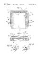
- FIG. 1is a cross sectional view of closure and lens assembly according to the present invention
- FIG. 2is a perspective view of the closure and lens assembly of FIG. 1;
- FIG. 3is a cross sectional view of the closure portion of FIG. 1 after it has been applied to a container package;
- FIG. 4is an enlarged cross sectional view of a portion of the closure of FIG. 1;
- FIG. 5Ais an enlarged view of a portion of FIG. 4;
- FIG. 5Bis an enlarged view of another embodiment of the portion of FIG. 4;
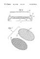
- FIG. 6is an exploded view of the closure and lens components of FIG. 1 before assembly
- FIG. 7is an exploded view of components of the lenticular lens
- FIG. 8Ais a view of a portion of a tool that may be employed to form the assembly of FIG. 1;
- FIG. 8Bis a view of a portion of another tool that may be employed to form the assembly of FIG. 1;
- FIG. 9is enlarged view of a portion of the assembly of FIG. 1 deformed by elevated internal pressure
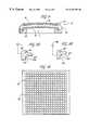
- FIG. 10is a view of a sheet of lenticular lenses
- FIG. 11is a view of closure and lens assembly tooling that may be employed during the process of forming the assembly of FIG. 1;
- FIG. 12is a view of a portion of FIG. 11 taken through line 12 — 12 ;
- FIG. 13is a side view of the assembly tooling of FIG. 11 in contact with the assembly of FIG. 1 .
- a dispenser package closure and lens assembly 10includes a closure 12 and a lenticular lens 11 .
- the closure assembly 10may be employed with dispensing packages 28 , such as containers used for beverages, medicines, and the like.
- closure 12includes a closure top 14 , a liner 15 , a retaining member 16 , a tubular skirt 18 , and a tamper evident ring 20 .
- closure top 14has an upper surface 22 and an opposing lower surface 24 , from which tubular skirt depends downward.
- the top 14 , retaining member 16 , tubular skirt 18 , and tamper evident ring 20are formed from a single piece of plastic, such as polypropylene, by injection molding, although other materials and processes are possible.
- Liner 15is disposed on the face of lower surface 24 .
- Retaining member 16rises upward from upper face 22 , and forms and overall circular shape as shown in FIG. 2 .
- retaining member 16is formed near the outer periphery of closure 12 , but may be spaced apart from the outer periphery to accommodate a lenticular lens of a smaller diameter than that shown in the Figures.
- Retaining member 16preferably forms a continuous member, as shown in the Figures, although the present invention also encompasses the retaining member 16 forming other shapes that correspond to lens of shapes other than as shown in FIG. 1 .
- retaining member 16may form a square, rectangular, or oval shape to correspond to a respectively shaped lens (not shown).
- the retaining membermay be discontinuous to form, for example, plural arcuate members (not shown) that may be disposed at the perimeter of a circular lens 11 .
- retaining member 16preferably includes a base member 17 a, a bend 17 b, and a rim portion 17 c that are integrally formed.
- Base member 17 aextends upward from upper surface 22 , and is preferably substantially perpendicular thereto on both the inboard and outboard side of base member 17 a.
- Base member 17 ayields to bend 17 b, which extends radially inward to form rim portion 17 c at its distal end.
- the inboard surface of base member 17 a and rim portion 17 cform an annular cavity 32 with upper surface 22 , as shown in FIG. 4 .
- the circumferential edge of lens 11is disposed in cavity 32 .
- Rim portion 17 chas a contact surface 17 d formed on its lower surface that contacts the edge of lens 11 to secure lens 11 against top surface 22 , as shown in FIGS. 1 and 3.
- FIG. 5Ashows retaining member 16 forming a sharp transition on its inboard (that is, facing radially inward or toward upper surface 22 ) surface such that the inboard surface of base member 17 a and the inboard surface of rim portion 17 c substantially form a right angle.
- the outboard portion of retaining member 16forms an annular chamfer or bevel between the outboard surfaces of base member 17 a and rim portion 17 c.
- FIG. 5Bshows another embodiment of retaining member 16 that has a gradually arcuate transition on both its inboard and outboard surfaces.
- the inboard and outboard rectilinear surfaces of base member 17 a and rim portion 17 c, respectively,may be perpendicular.
- base member 17 amay smoothly yield to rim portion 17 c such that both the inboard and outboard surfaces of retaining member 16 are continuously arcuate and lack rectilinear sides.
- Assembly 10preferably secures lens 11 to closure 12 without using adhesives. Securing lens 11 between contact surface 17 d of retaining member 16 and upper surface 22 of top 14 , as described herein, may prevent dislodging of lens 11 from closure 12 , especially in circumstances in which closure 12 is deformed, such as conditions of elevated internal pressure within dispensing package 28 .
- FIG. 9shows dispensing package and lens assembly 10 in a deformed state due to elevated internal pressure. Specifically, lens 11 may have been secured to closure 12 while top 14 was flat (as shown in FIG. 1 ). Assembly 10 may have been deformed upon filling and pressurizing of dispensing package 28 .
- the pressure within the dispensing package 28urges against liner 15 and lower surface 24 of top 14 to form a crown or convex shape.
- the present inventionhas an advantage of securing the lens 11 and closure 12 together at the edge of the lens 11 even while closure 12 has the crown shape shown in FIG. 9 .
- tubular skirt 18extends downward from the lower surface 24 of top 14 , and is sized to receive and seal the neck of the dispensing package 28 .
- skirt 18has a set of threads 26 that engage a set of matching threads 30 disposed on the outer surface of the neck of dispensing package 28 , as best shown in FIG. 1 .
- lenticular lens 11is composed of at least two alternately interleaved images forming abase image file 40 and an optical coating 42 .
- the interleaving processis preferably preformed on a computer with commercially available image editing soft ware, however, interleaving can also be accomplished by a manual means during or after the creation of the individual images.
- Lens 11has a preferred diameter of 24 mm (0.94 inches) and a preferred thickness of either 0.030 inches (0.76 mm) or 0.017 inches (0.43 mm).
- the present inventionencompasses lenses of any dimensions, as well as other objects that have a flat edge suitable for securing by rim portion 17 c.
- the optical coating 42is preferably formed from a substantially transparent thermosetting polymer.
- the polymer optical coating 42forms a non-planar surface defining a series of elongated parallel lenticular formations of narrow width and substantially uniform size and shape, forming parallel lenses 44 .
- These parallel lenses 44have a predetermined focal length correlated with the thickness of the polymer coating so as to focus substantially at the surface of the base image film 40 .
- the resulting base image film 40 and polymer coating 42form the composite lenticular lens 11 that provides a desired three-dimensional image, moving image, or multiple image visual effect.
- the preferred embodimentalso includes the tamper evident ring 20 , which circumferentially engages and frangibly connects to the open end of the tubular skirt 18 .
- the inner surface of tamper evident ring 20contains a flange 36 , which when placed on the dispensing package 28 , hooks under a lug 34 (as shown in FIG. 1) on the neck of dispensing package 28 .
- Tamper evident ring 20has sufficient resilience and elasticity so that flange 36 having a diameter slightly smaller than the diameter of lug 34 can be formed over the lug 34 .
- the frangible connectioncan withstand the compression forces during application of the closure to the dispensing package 28 but yields under tension upon removal.
- the force required to pull flange 36 over lug 34is greater than the force required to break the frangible connection. Accordingly, as the closure 12 is removed, the frangible connection breaks, separating tamper evident ring 20 from the remainder of closure 12 .
- the tamper evident ring 20remains on the neck of the dispensing package 28 to indicate that the original seal has been broken.
- a method for securing a decorative addition, such as lenticular lens 11 , to a dispensing package closureis provided.
- the closureis preferably closure 12 as described above.
- Lenticular lens 11preferably is die cut from a flat sheet 44 .
- flat sheet 44includes a grid of images, such as the 18 by 18 grid shown in FIG. 10 .
- each uncut image on flat sheet 44maybe larger than the finish lens 11 .
- each uncut imagehas a preferred diameter of 30 mm (1.18 inches), and the die (not shown) cuts a 24 mm (0.94 inch) diameter lens 11 that is insertable within retaining member 16 .
- lenticular lens 11may be placed on an undeforned closure 12 ′ (that is, a closure before the retaining member is bent or curled over an edge of the lens 11 ).
- Closure 12 ′has a retaining wall 16 ′ that preferably forms a cylindrical shape disposed on top of upper surface 22 .
- retaining wall 16 ′preferably has an inboard surface that is substantially perpendicular to upper surface 22 .
- the inside diameter of wall 16 ′matches the outside diameter of lenticular lens 11 , such that lens 11 may be easily inserted within sidewall 16 ′ to rest on upper surface 22 .
- the outboard surface of retaining wall 16 ′may also be perpendicular to upper surface 22 .
- Closure 12 ′may be mounted onto a pedestal to steady and hold closure 16 ′ during subsequent manufacturing steps.
- Lens 11may be inserted onto upper surface 22 before closure 12 ′ is inserted the pedestal, or closure 12 ′ may be placed on its assembly pedestal before lens 11 is placed within sidewall 16 ′.
- FIGS. 11 and 12show an assembly tool 50 that includes six pedestals 52 that may be used to hold closure 12 ′.
- pedestal 52has a shape that engages the interior of closure 12 such that closure 12 ′ may be firmly mounted onto pedestal 52 .
- Closure 12 ′may be mounted onto pedestal 52 by hand or by an automated machine process, as will be clear to persons familiar with such machinery and processes.
- a heated curling tool 46is urged against sidewall 16 ′ to form bend 17 b.
- curling tool 46includes a substantially vertical, circular base surface 17 a′, a substantially horizontal outer rim surface 17 c′, and an angled surface 17 b ′ therebetween.
- Surfaces 17 a′, 17 b′, and 17 c ′correspond to member portions 17 a, 17 b, and 17 c, respectively.
- Curling tool 46is heated by a heating system 48 such that contact with sidewall 16 ′ forms bend 17 b and rim portion 17 c of retaining member 16 , as will be understood by persons familiar with such plastic deforming processes.
- FIG. 13shows curling tool 46 in contact with closure 12 .
- FIG. 8Bshows another curling tool 46 ′ that has a substantially vertical, circular base surface 17 a′′, a substantially horizontal outer rim surface 17 c′′, and a smoothly curved surface 17 b′′ therebetween.
- Curling tool 46 ′may be used to form a shape of retaining member 16 as generally shown in FIG. 5 B.
- sidewall 16 ′is curled by curling tool 46 (or 46 ′) until contact surface 17 d contacts the outer face of lenticular lens 11 to securely fasten the lens to the closure 12 .
- Curling tool 46 (or 46 ′)may be raised away from closure 12 , and the substantially finished closure and lens assembly 10 may be removed from the pedestal 52 either by hand or by an automated process.
- a curling tool 46 (or 46 ′)will be disposed above each of the pedestals 52 such that multiple retaining walls 16 ′ may be curled with each downward stroke of the tooling.
- Closure and lens assembly 10may include the advantages of, for example, securely urging the lens 11 into contact with the closure top 14 , thereby preventing shifting or pivoting of the lens 11 with respect to the closure 12 .
- the present inventionencompasses loosely securing the lens 11 such that contact surface 17 d of the retaining member 16 may lightly contact lens 11 , or such that contact surface 17 d is spaced apart from the upper surface of lens 11 while the lens is disposed on closure top 14 . Loosely securing the lens 11 to the closure 12 may enable twisting of lens 11 relative to closure 12 .
- the present inventionencompasses lens 11 that are removable from closure 12 .
- the present inventionmay be embodied in other specific forms without departing from the spirit or essential attributes thereof.
- a lenticular lensis described, the present invention encompasses employing similar decorative objects, flat objects, disks and the like in place of, or in addition to a lenticular lens.
- lack of adhesiveis an advantage of the present invention, adhesives may be employed to augment securing the lens 11 within cavity 32 formed by retaining member 16 . Accordingly, reference should be made to the appended claims, rather than to the foregoing specification, as indicating the scope of the invention.
Landscapes
- Engineering & Computer Science (AREA)
- Theoretical Computer Science (AREA)
- Marketing (AREA)
- Physics & Mathematics (AREA)
- General Physics & Mathematics (AREA)
- Accounting & Taxation (AREA)
- Business, Economics & Management (AREA)
- Mechanical Engineering (AREA)
- Closures For Containers (AREA)
- Cartons (AREA)
- Prostheses (AREA)
- Materials For Medical Uses (AREA)
- Packaging Frangible Articles (AREA)
- Purses, Travelling Bags, Baskets, Or Suitcases (AREA)
Abstract
Description
Claims (12)
Priority Applications (10)
| Application Number | Priority Date | Filing Date | Title |
|---|---|---|---|
| US09/460,776US6394293B1 (en) | 1998-02-13 | 1999-12-14 | Closure having a lenticular lens |
| AU47177/01AAU4717701A (en) | 1999-12-14 | 2000-12-13 | Closure having a lenticular lens |
| MXPA02005925AMXPA02005925A (en) | 1999-12-14 | 2000-12-13 | Closure having a lenticular lens. |
| EP00992920AEP1237798B1 (en) | 1999-12-14 | 2000-12-13 | Closure having a lenticular lens |
| DE60011291TDE60011291T2 (en) | 1999-12-14 | 2000-12-13 | CLOSURE WITH A LENS GRID PLATE |
| AT00992920TATE268298T1 (en) | 1999-12-14 | 2000-12-13 | CLOSURE WITH A LENS PLATE |
| PCT/US2000/042784WO2001046034A2 (en) | 1999-12-14 | 2000-12-13 | Closure having a lenticular lens |
| ES00992920TES2220589T3 (en) | 1999-12-14 | 2000-12-13 | CLOSURE ELEMENT THAT HAS A LENTICULAR LENS. |
| BR0016378-3ABR0016378A (en) | 1999-12-14 | 2000-12-13 | Closure for use with a dispenser package, and method for attaching a lenticular lens to a closure for a dispenser package |
| US10/068,367US6694596B2 (en) | 1998-02-13 | 2002-02-05 | Closure having a lenticular lens |
Applications Claiming Priority (2)
| Application Number | Priority Date | Filing Date | Title |
|---|---|---|---|
| US09/023,539US6065623A (en) | 1998-02-13 | 1998-02-13 | Closure with lenticular lens insert |
| US09/460,776US6394293B1 (en) | 1998-02-13 | 1999-12-14 | Closure having a lenticular lens |
Related Parent Applications (1)
| Application Number | Title | Priority Date | Filing Date |
|---|---|---|---|
| US09/023,539Continuation-In-PartUS6065623A (en) | 1998-02-13 | 1998-02-13 | Closure with lenticular lens insert |
Related Child Applications (1)
| Application Number | Title | Priority Date | Filing Date |
|---|---|---|---|
| US10/068,367DivisionUS6694596B2 (en) | 1998-02-13 | 2002-02-05 | Closure having a lenticular lens |
Publications (1)
| Publication Number | Publication Date |
|---|---|
| US6394293B1true US6394293B1 (en) | 2002-05-28 |
Family
ID=23830035
Family Applications (2)
| Application Number | Title | Priority Date | Filing Date |
|---|---|---|---|
| US09/460,776Expired - Fee RelatedUS6394293B1 (en) | 1998-02-13 | 1999-12-14 | Closure having a lenticular lens |
| US10/068,367Expired - Fee RelatedUS6694596B2 (en) | 1998-02-13 | 2002-02-05 | Closure having a lenticular lens |
Family Applications After (1)
| Application Number | Title | Priority Date | Filing Date |
|---|---|---|---|
| US10/068,367Expired - Fee RelatedUS6694596B2 (en) | 1998-02-13 | 2002-02-05 | Closure having a lenticular lens |
Country Status (9)
| Country | Link |
|---|---|
| US (2) | US6394293B1 (en) |
| EP (1) | EP1237798B1 (en) |
| AT (1) | ATE268298T1 (en) |
| AU (1) | AU4717701A (en) |
| BR (1) | BR0016378A (en) |
| DE (1) | DE60011291T2 (en) |
| ES (1) | ES2220589T3 (en) |
| MX (1) | MXPA02005925A (en) |
| WO (1) | WO2001046034A2 (en) |
Cited By (15)
| Publication number | Priority date | Publication date | Assignee | Title |
|---|---|---|---|---|
| US20030223120A1 (en)* | 2002-05-28 | 2003-12-04 | Honorway Corporation Limited | Lenticular display unit |
| US20050011895A1 (en)* | 2003-07-14 | 2005-01-20 | Yi-Hung Lin | Cosmetics container having outstanding appearance |
| US20070065223A1 (en)* | 2005-09-16 | 2007-03-22 | Singer Steven A | Writing instrument having lenticular display surface |
| US20080107995A1 (en)* | 2004-04-19 | 2008-05-08 | Apparition Media, Llc. | Optical disc having lenticular surface and method of manufacturing |
| WO2011095932A1 (en) | 2010-02-02 | 2011-08-11 | Hasan Hakan Artun | A package having three dimensional label and production method thereof |
| US20110315566A1 (en)* | 2010-06-29 | 2011-12-29 | Clever Girl Concepts, LLC | Customizable storage container system |
| WO2015101649A1 (en)* | 2013-12-31 | 2015-07-09 | Societe Anonyme Des Eaux Minerales D'evian | Cap for closing the neck finish of a container and method for manufacturing said cap |
| USD750314S1 (en)* | 2014-12-22 | 2016-02-23 | Cree, Inc. | Photocontrol receptacle for lighting fixture |
| US20160159536A1 (en)* | 2013-08-29 | 2016-06-09 | Sacmi Cooperativa Meccanici Imola Societa Cooperativa | Safety capsule for containers |
| USD767405S1 (en)* | 2015-09-21 | 2016-09-27 | Celgene Corporation | Bottle with cap |
| US20180312312A1 (en)* | 2015-11-23 | 2018-11-01 | Daniel Acevedo | Tamper-Evident Double-Lid For Packaging And Containers |
| USD848239S1 (en)* | 2017-10-06 | 2019-05-14 | Harman International Industries, Incorporated | Control knob |
| USD871905S1 (en)* | 2015-05-11 | 2020-01-07 | Silgan White Cap LLC | Closure |
| WO2021061737A1 (en)* | 2019-09-27 | 2021-04-01 | Waymo Llc | Lens retainer ring with compliant element |
| USD980690S1 (en)* | 2020-02-14 | 2023-03-14 | Samuel Heath & Sons Plc | Control handle for a tap |
Families Citing this family (21)
| Publication number | Priority date | Publication date | Assignee | Title |
|---|---|---|---|---|
| US20070199913A1 (en)* | 2003-02-27 | 2007-08-30 | Erie County Plastics Corporation | Container and container closure with secure molded three dimensional image |
| US20100072163A1 (en)* | 2008-09-23 | 2010-03-25 | Bio Clinical Development, Inc. | Bottle cap |
| US20110160680A1 (en)* | 2009-12-29 | 2011-06-30 | Cook Incorporated | Wire guide with cannula |
| US20120012551A1 (en)* | 2010-07-16 | 2012-01-19 | Russell Sinacori | Container having interchangeable sleeve |
| USD675097S1 (en)* | 2011-03-01 | 2013-01-29 | Burke Jr Richard Million | Container cap with protective cover |
| US8556095B1 (en)* | 2011-10-06 | 2013-10-15 | Sawako Yamaguchi | Threaded bottle cap having magnetically detachable decoration |
| CN103287703A (en)* | 2012-02-29 | 2013-09-11 | 和盛清新股份有限公司 | Cup cover with advertisement carrier |
| EP2641844B1 (en) | 2012-03-20 | 2016-10-26 | Kraft Foods R & D, Inc. | Decorative packaging element |
| DE102014100588A1 (en)* | 2014-01-20 | 2015-07-23 | Bericap Gmbh & Co. Kg | Plastic closure with warranty surface |
| US10239667B2 (en) | 2014-06-18 | 2019-03-26 | Sonoco Development, Inc. | Closure for retort container |
| JP6601103B2 (en)* | 2015-09-30 | 2019-11-06 | サンスター株式会社 | Measuring cap and container |
| US11779520B1 (en) | 2018-07-02 | 2023-10-10 | Patrick Vitello | Closure for a medical dispenser including a one-piece tip cap |
| US11793987B1 (en) | 2018-07-02 | 2023-10-24 | Patrick Vitello | Flex tec closure assembly for a medical dispenser |
| US11857751B1 (en) | 2018-07-02 | 2024-01-02 | International Medical Industries Inc. | Assembly for a medical connector |
| US11690994B1 (en) | 2018-07-13 | 2023-07-04 | Robert Banik | Modular medical connector |
| US11911339B1 (en) | 2019-08-15 | 2024-02-27 | Peter Lehel | Universal additive port cap |
| US11697527B1 (en) | 2019-09-11 | 2023-07-11 | Logan Hendren | Tamper evident closure assembly |
| US11904149B1 (en) | 2020-02-18 | 2024-02-20 | Jonathan Vitello | Oral tamper evident closure with retained indicator |
| US12070591B1 (en) | 2020-12-14 | 2024-08-27 | Patrick Vitello | Snap action tamper evident closure assembly |
| US11872187B1 (en) | 2020-12-28 | 2024-01-16 | Jonathan Vitello | Tamper evident seal for a vial cover |
| US12172803B1 (en) | 2021-10-04 | 2024-12-24 | Patrick Vitello | Tamper evident integrated closure |
Citations (49)
| Publication number | Priority date | Publication date | Assignee | Title |
|---|---|---|---|---|
| US1395594A (en) | 1919-12-15 | 1921-11-01 | Raymond O Pfefferle | Box or receptacle |
| US1735431A (en) | 1928-08-15 | 1929-11-12 | August Goertz & Co Inc | Means for decorating boxes |
| US1918243A (en) | 1931-07-01 | 1933-07-18 | Caron Corp | Stopper |
| US1975703A (en) | 1933-01-16 | 1934-10-02 | Vitale Giorgio | Fluid-tight glass closure for metallic containers |
| US2046745A (en)* | 1933-05-12 | 1936-07-07 | Whitehead & Hoag Co | Container cap |
| US2055693A (en) | 1934-11-22 | 1936-09-29 | Lewin Falk | Capsule for containers |
| US2129406A (en)* | 1937-03-05 | 1938-09-06 | Fred B Cole | Milk bottle cap |
| US2168594A (en)* | 1930-04-21 | 1939-08-08 | Anchor Cap & Closure Corp | Closure cap |
| US2997788A (en) | 1958-01-06 | 1961-08-29 | Cleveland Cleaner & Paste Comp | Display lid |
| US3421653A (en)* | 1967-04-11 | 1969-01-14 | Robert E Whaley | Container closure |
| US3538632A (en) | 1967-06-08 | 1970-11-10 | Pictorial Prod Inc | Lenticular device and method for providing same |
| FR2045700A1 (en) | 1969-06-23 | 1971-03-05 | Tournus Moulage | Bottle stopper (polypropylene) with resil- - ient seal diaphragm |
| US4034882A (en) | 1975-10-15 | 1977-07-12 | Rockware Group Limited | Container closures |
| US4111322A (en)* | 1976-05-25 | 1978-09-05 | Albert Obrist Ag | Synthetic plastic cap for bottles |
| USD249935S (en) | 1976-10-18 | 1978-10-17 | Williams Robert G | Container lid |
| US4356935A (en) | 1979-04-18 | 1982-11-02 | Kardon Industries, Inc. | Method and apparatus for storing and dispensing fluid foodstuff |
| US4389802A (en) | 1981-11-12 | 1983-06-28 | Champion International Corporation | Scalloped paperboard insert for use with plastic lid |
| US4408702A (en) | 1981-11-06 | 1983-10-11 | William Horvath | Automatic dispenser cap |
| US4420527A (en) | 1980-09-05 | 1983-12-13 | Rexham Corporation | Thermoset relief patterned sheet |
| GB2130565A (en) | 1982-09-29 | 1984-06-06 | Patent Dev International Ltd | Container closures |
| US4541727A (en) | 1975-12-16 | 1985-09-17 | Rosenthal Bruce A | Lenticular optical system |
| US4747499A (en) | 1983-02-14 | 1988-05-31 | Sunbeam Plastics Corporation | Tamper indicating closure with adhesive-attached gasket |
| US4756437A (en) | 1986-02-27 | 1988-07-12 | W. R. Grace & Co. | Closure cap with vapor impermeable lamina |
| US4793500A (en) | 1987-11-10 | 1988-12-27 | Harding Claude J | Tamper indicator |
| USD315507S (en) | 1987-06-01 | 1991-03-19 | Anchor Hocking Corporation | Closure cap |
| US5022545A (en) | 1990-08-03 | 1991-06-11 | Continental White Cap, Inc. | Tamper evident closure |
| USD318804S (en) | 1987-06-01 | 1991-08-06 | Anchor Hocking Corporation | Tamper-evident closure |
| US5072844A (en) | 1990-02-28 | 1991-12-17 | Aisin Seiki Kabushiki Kaisha | Reservoir cap |
| US5113213A (en) | 1989-01-13 | 1992-05-12 | Sandor Ellen R | Computer-generated autostereography method and apparatus |
| US5119963A (en) | 1990-06-29 | 1992-06-09 | Continental White Cap, Inc. | Mechanical button and button enhancement techniques |
| US5189531A (en)* | 1988-10-17 | 1993-02-23 | August DeFazio | Hologram production |
| US5261547A (en) | 1991-12-30 | 1993-11-16 | Finke Stephan J | Methods and combinations for sealing corked bottles |
| US5273173A (en) | 1990-02-05 | 1993-12-28 | Lynes Holding S.A. | Screw top |
| US5285238A (en) | 1992-08-12 | 1994-02-08 | Quad/Tech, Inc. | Method for forming a graphic image web |
| USD353521S (en) | 1993-07-26 | 1994-12-20 | Aladdin Industries, Inc. | Container |
| US5400915A (en) | 1994-03-21 | 1995-03-28 | Kennedy; Michael R. | Container window seal |
| USD359685S (en) | 1991-10-28 | 1995-06-27 | Portola Packaging, Inc. | Container closure |
| US5456375A (en) | 1992-05-20 | 1995-10-10 | Specialised Purchasing Concepts Unit Trust | Tamper evident cap and container |
| US5474194A (en) | 1990-07-09 | 1995-12-12 | Continental White Cap, Inc. | Closure with irreversible color change system |
| US5494445A (en)* | 1989-12-07 | 1996-02-27 | Yoshi Sekiguchi | Process and display with moveable images |
| US5497879A (en) | 1994-10-07 | 1996-03-12 | Kao; Richard C. | Film status cap |
| GB2298188A (en)* | 1995-02-27 | 1996-08-28 | David Gifford Burder | Lenticular transparent box |
| US5592766A (en) | 1995-06-07 | 1997-01-14 | Mygatt; Leonard T. | Container lid/closure with printed closure insert |
| WO1997035779A1 (en) | 1996-03-26 | 1997-10-02 | Carnaudmetalbox Plc | Composite closure, method for assembling it and method for closing a container with it |
| USD389062S (en) | 1996-12-06 | 1998-01-13 | Phoenix Closures, Inc. | Closure vent arrangement cap |
| US5839592A (en) | 1995-06-09 | 1998-11-24 | Anchor Hocking Packaging Co. | Plastic closure |
| US5896686A (en)* | 1996-12-03 | 1999-04-27 | Howes; James P. | Multi-image prize award and method therefor |
| US5904266A (en)* | 1997-10-21 | 1999-05-18 | Kraft Foods Inc. | Product package and stackable lid assembly therefor |
| US6065623A (en)* | 1998-02-13 | 2000-05-23 | Crown Cork & Seal Technologies Corporation | Closure with lenticular lens insert |
Family Cites Families (2)
| Publication number | Priority date | Publication date | Assignee | Title |
|---|---|---|---|---|
| US673416A (en)* | 1900-08-02 | 1901-05-07 | Thomas Charlton Booth | Can-closure. |
| US2500897A (en)* | 1946-04-15 | 1950-03-14 | Friedman Theodore | Retaining body having a shouldered recess for a mirror or the like |
- 1999
- 1999-12-14USUS09/460,776patent/US6394293B1/ennot_activeExpired - Fee Related
- 2000
- 2000-12-13AUAU47177/01Apatent/AU4717701A/ennot_activeAbandoned
- 2000-12-13EPEP00992920Apatent/EP1237798B1/ennot_activeExpired - Lifetime
- 2000-12-13ATAT00992920Tpatent/ATE268298T1/ennot_activeIP Right Cessation
- 2000-12-13DEDE60011291Tpatent/DE60011291T2/ennot_activeExpired - Fee Related
- 2000-12-13ESES00992920Tpatent/ES2220589T3/ennot_activeExpired - Lifetime
- 2000-12-13BRBR0016378-3Apatent/BR0016378A/ennot_activeIP Right Cessation
- 2000-12-13WOPCT/US2000/042784patent/WO2001046034A2/enactiveIP Right Grant
- 2000-12-13MXMXPA02005925Apatent/MXPA02005925A/enactiveIP Right Grant
- 2002
- 2002-02-05USUS10/068,367patent/US6694596B2/ennot_activeExpired - Fee Related
Patent Citations (49)
| Publication number | Priority date | Publication date | Assignee | Title |
|---|---|---|---|---|
| US1395594A (en) | 1919-12-15 | 1921-11-01 | Raymond O Pfefferle | Box or receptacle |
| US1735431A (en) | 1928-08-15 | 1929-11-12 | August Goertz & Co Inc | Means for decorating boxes |
| US2168594A (en)* | 1930-04-21 | 1939-08-08 | Anchor Cap & Closure Corp | Closure cap |
| US1918243A (en) | 1931-07-01 | 1933-07-18 | Caron Corp | Stopper |
| US1975703A (en) | 1933-01-16 | 1934-10-02 | Vitale Giorgio | Fluid-tight glass closure for metallic containers |
| US2046745A (en)* | 1933-05-12 | 1936-07-07 | Whitehead & Hoag Co | Container cap |
| US2055693A (en) | 1934-11-22 | 1936-09-29 | Lewin Falk | Capsule for containers |
| US2129406A (en)* | 1937-03-05 | 1938-09-06 | Fred B Cole | Milk bottle cap |
| US2997788A (en) | 1958-01-06 | 1961-08-29 | Cleveland Cleaner & Paste Comp | Display lid |
| US3421653A (en)* | 1967-04-11 | 1969-01-14 | Robert E Whaley | Container closure |
| US3538632A (en) | 1967-06-08 | 1970-11-10 | Pictorial Prod Inc | Lenticular device and method for providing same |
| FR2045700A1 (en) | 1969-06-23 | 1971-03-05 | Tournus Moulage | Bottle stopper (polypropylene) with resil- - ient seal diaphragm |
| US4034882A (en) | 1975-10-15 | 1977-07-12 | Rockware Group Limited | Container closures |
| US4541727A (en) | 1975-12-16 | 1985-09-17 | Rosenthal Bruce A | Lenticular optical system |
| US4111322A (en)* | 1976-05-25 | 1978-09-05 | Albert Obrist Ag | Synthetic plastic cap for bottles |
| USD249935S (en) | 1976-10-18 | 1978-10-17 | Williams Robert G | Container lid |
| US4356935A (en) | 1979-04-18 | 1982-11-02 | Kardon Industries, Inc. | Method and apparatus for storing and dispensing fluid foodstuff |
| US4420527A (en) | 1980-09-05 | 1983-12-13 | Rexham Corporation | Thermoset relief patterned sheet |
| US4408702A (en) | 1981-11-06 | 1983-10-11 | William Horvath | Automatic dispenser cap |
| US4389802A (en) | 1981-11-12 | 1983-06-28 | Champion International Corporation | Scalloped paperboard insert for use with plastic lid |
| GB2130565A (en) | 1982-09-29 | 1984-06-06 | Patent Dev International Ltd | Container closures |
| US4747499A (en) | 1983-02-14 | 1988-05-31 | Sunbeam Plastics Corporation | Tamper indicating closure with adhesive-attached gasket |
| US4756437A (en) | 1986-02-27 | 1988-07-12 | W. R. Grace & Co. | Closure cap with vapor impermeable lamina |
| USD315507S (en) | 1987-06-01 | 1991-03-19 | Anchor Hocking Corporation | Closure cap |
| USD318804S (en) | 1987-06-01 | 1991-08-06 | Anchor Hocking Corporation | Tamper-evident closure |
| US4793500A (en) | 1987-11-10 | 1988-12-27 | Harding Claude J | Tamper indicator |
| US5189531A (en)* | 1988-10-17 | 1993-02-23 | August DeFazio | Hologram production |
| US5113213A (en) | 1989-01-13 | 1992-05-12 | Sandor Ellen R | Computer-generated autostereography method and apparatus |
| US5494445A (en)* | 1989-12-07 | 1996-02-27 | Yoshi Sekiguchi | Process and display with moveable images |
| US5273173A (en) | 1990-02-05 | 1993-12-28 | Lynes Holding S.A. | Screw top |
| US5072844A (en) | 1990-02-28 | 1991-12-17 | Aisin Seiki Kabushiki Kaisha | Reservoir cap |
| US5119963A (en) | 1990-06-29 | 1992-06-09 | Continental White Cap, Inc. | Mechanical button and button enhancement techniques |
| US5474194A (en) | 1990-07-09 | 1995-12-12 | Continental White Cap, Inc. | Closure with irreversible color change system |
| US5022545A (en) | 1990-08-03 | 1991-06-11 | Continental White Cap, Inc. | Tamper evident closure |
| USD359685S (en) | 1991-10-28 | 1995-06-27 | Portola Packaging, Inc. | Container closure |
| US5261547A (en) | 1991-12-30 | 1993-11-16 | Finke Stephan J | Methods and combinations for sealing corked bottles |
| US5456375A (en) | 1992-05-20 | 1995-10-10 | Specialised Purchasing Concepts Unit Trust | Tamper evident cap and container |
| US5285238A (en) | 1992-08-12 | 1994-02-08 | Quad/Tech, Inc. | Method for forming a graphic image web |
| USD353521S (en) | 1993-07-26 | 1994-12-20 | Aladdin Industries, Inc. | Container |
| US5400915A (en) | 1994-03-21 | 1995-03-28 | Kennedy; Michael R. | Container window seal |
| US5497879A (en) | 1994-10-07 | 1996-03-12 | Kao; Richard C. | Film status cap |
| GB2298188A (en)* | 1995-02-27 | 1996-08-28 | David Gifford Burder | Lenticular transparent box |
| US5592766A (en) | 1995-06-07 | 1997-01-14 | Mygatt; Leonard T. | Container lid/closure with printed closure insert |
| US5839592A (en) | 1995-06-09 | 1998-11-24 | Anchor Hocking Packaging Co. | Plastic closure |
| WO1997035779A1 (en) | 1996-03-26 | 1997-10-02 | Carnaudmetalbox Plc | Composite closure, method for assembling it and method for closing a container with it |
| US5896686A (en)* | 1996-12-03 | 1999-04-27 | Howes; James P. | Multi-image prize award and method therefor |
| USD389062S (en) | 1996-12-06 | 1998-01-13 | Phoenix Closures, Inc. | Closure vent arrangement cap |
| US5904266A (en)* | 1997-10-21 | 1999-05-18 | Kraft Foods Inc. | Product package and stackable lid assembly therefor |
| US6065623A (en)* | 1998-02-13 | 2000-05-23 | Crown Cork & Seal Technologies Corporation | Closure with lenticular lens insert |
Non-Patent Citations (1)
| Title |
|---|
| QDI refines focus; dimensional imaging sales takeoff, QDI, Nov./Dec. 1995. |
Cited By (25)
| Publication number | Priority date | Publication date | Assignee | Title |
|---|---|---|---|---|
| US20030223120A1 (en)* | 2002-05-28 | 2003-12-04 | Honorway Corporation Limited | Lenticular display unit |
| US20050011895A1 (en)* | 2003-07-14 | 2005-01-20 | Yi-Hung Lin | Cosmetics container having outstanding appearance |
| US20080107995A1 (en)* | 2004-04-19 | 2008-05-08 | Apparition Media, Llc. | Optical disc having lenticular surface and method of manufacturing |
| US20070065223A1 (en)* | 2005-09-16 | 2007-03-22 | Singer Steven A | Writing instrument having lenticular display surface |
| WO2011095932A1 (en) | 2010-02-02 | 2011-08-11 | Hasan Hakan Artun | A package having three dimensional label and production method thereof |
| US20110315566A1 (en)* | 2010-06-29 | 2011-12-29 | Clever Girl Concepts, LLC | Customizable storage container system |
| US20160159536A1 (en)* | 2013-08-29 | 2016-06-09 | Sacmi Cooperativa Meccanici Imola Societa Cooperativa | Safety capsule for containers |
| US10392173B2 (en)* | 2013-08-29 | 2019-08-27 | Sacmi Cooperativa Meccanici Imola Societa′ Cooperativa | Safety capsule for containers |
| US10071840B2 (en) | 2013-12-31 | 2018-09-11 | Societe Anonyme Des Eaux Minerales D'evian, “S.A.E.M.E” | Cap for closing the neck finish of a container and method for manufacturing said cap |
| CN106061859A (en)* | 2013-12-31 | 2016-10-26 | 埃维昂矿泉水有限公司 | Cap for closing the neck finish of a container and method for manufacturing said cap |
| CN106061859B (en)* | 2013-12-31 | 2018-08-21 | 埃维昂矿泉水有限公司 | The lid of bottleneck for being closed container and the method for manufacturing the lid |
| WO2015101649A1 (en)* | 2013-12-31 | 2015-07-09 | Societe Anonyme Des Eaux Minerales D'evian | Cap for closing the neck finish of a container and method for manufacturing said cap |
| USD750314S1 (en)* | 2014-12-22 | 2016-02-23 | Cree, Inc. | Photocontrol receptacle for lighting fixture |
| USD934074S1 (en) | 2015-05-11 | 2021-10-26 | Silgan White Cap LLC | Closure |
| USD1042132S1 (en) | 2015-05-11 | 2024-09-17 | Silgan White Cap LLC | Closure |
| USD993769S1 (en) | 2015-05-11 | 2023-08-01 | Silgan White Cap LLC | Closure |
| USD871905S1 (en)* | 2015-05-11 | 2020-01-07 | Silgan White Cap LLC | Closure |
| USD767405S1 (en)* | 2015-09-21 | 2016-09-27 | Celgene Corporation | Bottle with cap |
| US10625913B2 (en)* | 2015-11-23 | 2020-04-21 | Daniel Acevedo | Tamper-evident double-lid for packaging and containers |
| US20180312312A1 (en)* | 2015-11-23 | 2018-11-01 | Daniel Acevedo | Tamper-Evident Double-Lid For Packaging And Containers |
| USD848239S1 (en)* | 2017-10-06 | 2019-05-14 | Harman International Industries, Incorporated | Control knob |
| WO2021061737A1 (en)* | 2019-09-27 | 2021-04-01 | Waymo Llc | Lens retainer ring with compliant element |
| US11402602B2 (en) | 2019-09-27 | 2022-08-02 | Waymo Llc | Lens retainer ring with compliant element |
| US12210207B2 (en) | 2019-09-27 | 2025-01-28 | Waymo Llc | Lens retainer ring with compliant element |
| USD980690S1 (en)* | 2020-02-14 | 2023-03-14 | Samuel Heath & Sons Plc | Control handle for a tap |
Also Published As
| Publication number | Publication date |
|---|---|
| ES2220589T3 (en) | 2004-12-16 |
| AU4717701A (en) | 2001-07-03 |
| US6694596B2 (en) | 2004-02-24 |
| ATE268298T1 (en) | 2004-06-15 |
| EP1237798B1 (en) | 2004-06-02 |
| DE60011291D1 (en) | 2004-07-08 |
| BR0016378A (en) | 2002-08-27 |
| MXPA02005925A (en) | 2003-01-28 |
| US20020079281A1 (en) | 2002-06-27 |
| WO2001046034A3 (en) | 2002-02-07 |
| EP1237798A2 (en) | 2002-09-11 |
| DE60011291T2 (en) | 2005-07-14 |
| WO2001046034A2 (en) | 2001-06-28 |
Similar Documents
| Publication | Publication Date | Title |
|---|---|---|
| US6394293B1 (en) | Closure having a lenticular lens | |
| US6065623A (en) | Closure with lenticular lens insert | |
| CN103687516B (en) | Goblet and goblet assembly | |
| US4844270A (en) | Screw cap jar | |
| JPS5828161B2 (en) | Method of forming sealed containers | |
| JPH0329756A (en) | Cap to seal neck of bottle | |
| JPS63502266A (en) | Seal cap without liner and its molding method | |
| JPH08504710A (en) | Closure with insert liner | |
| EP0868359A1 (en) | Tamper-evident leak-tight closure for containers | |
| GB2432152A (en) | Cap with visible tamper-indicating seal | |
| US20120292315A1 (en) | Beverage glass and beverage glass assembly | |
| US20030080128A1 (en) | Method of making an improved jar container | |
| US2831613A (en) | Supplementary upper walls for containers | |
| US4964205A (en) | Method for making screw cap jar | |
| NL8202146A (en) | IMPROVED CLOSING CAP AND METHOD FOR MAKING THE SAME | |
| AU2001276417B2 (en) | Overcap closures with rolled apron | |
| EP1178933B1 (en) | Thin-walled container and lid, and also a method for making | |
| US3323276A (en) | Closures and methods for applying same | |
| JP4514073B2 (en) | Molding method of can lid with identification mark | |
| US3743128A (en) | Closure and closure die | |
| CA2536867C (en) | Composite closure having an insert with a peripheral curl | |
| US11136168B2 (en) | Package with tamper evident security band | |
| CA2305227A1 (en) | Lined closure for containers of differing finish configurations | |
| US20230211403A1 (en) | Method for manufacturing container and apparatus for manufacturing container | |
| JPH0637930Y2 (en) | Resin container |
Legal Events
| Date | Code | Title | Description |
|---|---|---|---|
| AS | Assignment | Owner name:CROWN CORK & SEAL TECHNOLOGIES CORPORATION, ILLIN Free format text:ASSIGNMENT OF ASSIGNORS INTEREST;ASSIGNORS:HIERZER, VALENTIN;SUNGSUK KIM, STEVE;REEL/FRAME:010807/0065;SIGNING DATES FROM 20000307 TO 20000328 | |
| AS | Assignment | Owner name:CHASE MANHATTAN BANK, AS COLLATERAL AGENT, THE, NEW YORK Free format text:SECURITY INTEREST;ASSIGNOR:CROWN CORK & SEAL TECHNOLOGIES CORPORATION;REEL/FRAME:011667/0001 Effective date:20010302 Owner name:CHASE MANHATTAN BANK, AS COLLATERAL AGENT, THE, NE Free format text:SECURITY INTEREST;ASSIGNOR:CROWN CORK & SEAL TECHNOLOGIES CORPORATION;REEL/FRAME:011667/0001 Effective date:20010302 | |
| AS | Assignment | Owner name:CROWN CORK & SEAL TECHNOLOGIES, ILLINOIS Free format text:RELEASE OF SECURITY INTEREST;ASSIGNOR:JPMORGAN CHASE BANK;REEL/FRAME:013798/0522 Effective date:20030226 | |
| AS | Assignment | Owner name:CITICORP NORTH AMERICA, INC., AS COLLATERAL AGENT, Free format text:SECURITY INTEREST;ASSIGNOR:CROWN CORK & SEAL TECHNOLOGIES CORPORATION;REEL/FRAME:013791/0846 Effective date:20030226 | |
| AS | Assignment | Owner name:CITICORP NORTH AMERICA, INC., NEW YORK Free format text:SECURITY AGREEMENT;ASSIGNOR:CROWN TECHNOLOGIES PACKAGING CORPORATION;REEL/FRAME:016283/0612 Effective date:20040901 | |
| FPAY | Fee payment | Year of fee payment:4 | |
| AS | Assignment | Owner name:CROWN OBRIST GMBH, SWITZERLAND Free format text:ASSIGNMENT OF ASSIGNORS INTEREST;ASSIGNOR:CROWN PACKAGING TECHNOLOGY, INC.;REEL/FRAME:017546/0384 Effective date:20051011 | |
| AS | Assignment | Owner name:CROWN HOLDINGS, INC., PENNSYLVANIA Free format text:RELEASE BY SECURED PARTY;ASSIGNOR:CITICORP NORTH AMERICA, INC.;REEL/FRAME:018296/0067 Effective date:20051011 Owner name:CROWN PACKAGING TECHNOLOGY, INC., ILLINOIS Free format text:CHANGE OF NAME;ASSIGNOR:CROWN CORK & SEAL TECHNOLOGIES CORPORATION;REEL/FRAME:018291/0878 Effective date:20031103 Owner name:OBRIST CLOSURES SWITZERLAND GMBH, SWITZERLAND Free format text:CHANGE OF NAME;ASSIGNOR:CROWN OBRIST GMBH;REEL/FRAME:018291/0944 Effective date:20051223 | |
| REMI | Maintenance fee reminder mailed | ||
| LAPS | Lapse for failure to pay maintenance fees | ||
| STCH | Information on status: patent discontinuation | Free format text:PATENT EXPIRED DUE TO NONPAYMENT OF MAINTENANCE FEES UNDER 37 CFR 1.362 | |
| FP | Lapsed due to failure to pay maintenance fee | Effective date:20100528 | |
| AS | Assignment | Owner name:CROWN PACKAGING TECHNOLOGY, INC., ILLINOIS Free format text:RELEASE BY SECURED PARTY;ASSIGNOR:CITICORP NORTH AMERICA, INC.;REEL/FRAME:032449/0248 Effective date:20140314 Owner name:CROWN PACKAGING TECHNOLOGY, INC., ILLINOIS Free format text:RELEASE BY SECURED PARTY;ASSIGNOR:CITICORP NORTH AMERICA, INC.;REEL/FRAME:032449/0281 Effective date:20140314 |