US6391025B1 - Electrosurgical scalpel and methods for tissue cutting - Google Patents
Electrosurgical scalpel and methods for tissue cuttingDownload PDFInfo
- Publication number
- US6391025B1 US6391025B1US09/041,934US4193498AUS6391025B1US 6391025 B1US6391025 B1US 6391025B1US 4193498 AUS4193498 AUS 4193498AUS 6391025 B1US6391025 B1US 6391025B1
- Authority
- US
- United States
- Prior art keywords
- electrode
- tissue
- target site
- probe
- ligament
- Prior art date
- Legal status (The legal status is an assumption and is not a legal conclusion. Google has not performed a legal analysis and makes no representation as to the accuracy of the status listed.)
- Expired - Fee Related
Links
- 238000000034methodMethods0.000titleclaimsabstractdescription136
- 238000005520cutting processMethods0.000titleclaimsabstractdescription44
- 239000000523sampleSubstances0.000claimsabstractdescription145
- 239000012530fluidSubstances0.000claimsabstractdescription142
- 210000003041ligamentAnatomy0.000claimsabstractdescription47
- 210000000426patellar ligamentAnatomy0.000claimsabstractdescription11
- 210000003127kneeAnatomy0.000claimsabstractdescription9
- 230000036961partial effectEffects0.000claimsabstractdescription8
- 210000001519tissueAnatomy0.000claimsdescription178
- 230000000694effectsEffects0.000claimsdescription17
- 238000010494dissociation reactionMethods0.000claimsdescription15
- 230000005593dissociationsEffects0.000claimsdescription15
- 210000002683footAnatomy0.000claimsdescription15
- 239000002245particleSubstances0.000claimsdescription9
- 210000001015abdomenAnatomy0.000claimsdescription3
- 210000004207dermisAnatomy0.000claimsdescription3
- 210000001513elbowAnatomy0.000claimsdescription3
- 210000002615epidermisAnatomy0.000claimsdescription3
- 210000000115thoracic cavityAnatomy0.000claimsdescription3
- 238000002679ablationMethods0.000abstractdescription37
- 230000037361pathwayEffects0.000abstractdescription8
- 230000008569processEffects0.000abstractdescription8
- 210000002414legAnatomy0.000abstractdescription5
- 231100000241scarToxicity0.000abstractdescription5
- 208000032544CicatrixDiseases0.000abstractdescription4
- 230000037387scarsEffects0.000abstractdescription4
- 208000012641Pigmentation diseaseDiseases0.000abstractdescription3
- 230000019612pigmentationEffects0.000abstractdescription3
- 230000003685thermal hair damageEffects0.000abstractdescription3
- 231100000216vascular lesionToxicity0.000abstractdescription3
- 210000003462veinAnatomy0.000abstractdescription3
- 238000004381surface treatmentMethods0.000abstractdescription2
- FAPWRFPIFSIZLT-UHFFFAOYSA-MSodium chlorideChemical compound[Na+].[Cl-]FAPWRFPIFSIZLT-UHFFFAOYSA-M0.000description19
- 239000010410layerSubstances0.000description19
- 238000005345coagulationMethods0.000description18
- 230000015271coagulationEffects0.000description18
- BASFCYQUMIYNBI-UHFFFAOYSA-NplatinumChemical compound[Pt]BASFCYQUMIYNBI-UHFFFAOYSA-N0.000description16
- 239000007788liquidSubstances0.000description14
- 230000005684electric fieldEffects0.000description13
- 238000010438heat treatmentMethods0.000description13
- 230000009467reductionEffects0.000description11
- 238000001356surgical procedureMethods0.000description11
- 239000000463materialSubstances0.000description10
- PNEYBMLMFCGWSK-UHFFFAOYSA-Naluminium oxideInorganic materials[O-2].[O-2].[O-2].[Al+3].[Al+3]PNEYBMLMFCGWSK-UHFFFAOYSA-N0.000description9
- 239000000919ceramicSubstances0.000description9
- 239000011159matrix materialSubstances0.000description9
- MCMNRKCIXSYSNV-UHFFFAOYSA-NZirconium dioxideChemical compoundO=[Zr]=OMCMNRKCIXSYSNV-UHFFFAOYSA-N0.000description8
- 229910052697platinumInorganic materials0.000description8
- 235000012431wafersNutrition0.000description8
- 230000008878couplingEffects0.000description7
- 238000010168coupling processMethods0.000description7
- 238000005859coupling reactionMethods0.000description7
- 230000006378damageEffects0.000description7
- 230000004907fluxEffects0.000description7
- 230000023597hemostasisEffects0.000description7
- 230000017074necrotic cell deathEffects0.000description7
- 238000002271resectionMethods0.000description7
- 230000008016vaporizationEffects0.000description7
- RTAQQCXQSZGOHL-UHFFFAOYSA-NTitaniumChemical compound[Ti]RTAQQCXQSZGOHL-UHFFFAOYSA-N0.000description6
- 239000004020conductorSubstances0.000description6
- 210000003128headAnatomy0.000description6
- 230000000670limiting effectEffects0.000description6
- 210000000214mouthAnatomy0.000description6
- 239000003566sealing materialSubstances0.000description6
- 210000003491skinAnatomy0.000description6
- 239000011780sodium chlorideSubstances0.000description6
- 229910052719titaniumInorganic materials0.000description6
- 239000010936titaniumSubstances0.000description6
- 238000009834vaporizationMethods0.000description6
- 206010028980NeoplasmDiseases0.000description5
- 239000003990capacitorSubstances0.000description5
- 230000008602contractionEffects0.000description5
- 239000007789gasSubstances0.000description5
- 239000011521glassSubstances0.000description5
- 201000010260leiomyomaDiseases0.000description5
- 229910052751metalInorganic materials0.000description5
- 210000003800pharynxAnatomy0.000description5
- PXHVJJICTQNCMI-UHFFFAOYSA-NNickelChemical compound[Ni]PXHVJJICTQNCMI-UHFFFAOYSA-N0.000description4
- 229910045601alloyInorganic materials0.000description4
- 239000000956alloySubstances0.000description4
- 230000000740bleeding effectEffects0.000description4
- 239000008280bloodSubstances0.000description4
- 210000004369bloodAnatomy0.000description4
- 210000004204blood vesselAnatomy0.000description4
- 230000008018meltingEffects0.000description4
- 238000002844meltingMethods0.000description4
- 239000002184metalSubstances0.000description4
- 210000001331noseAnatomy0.000description4
- 239000004033plasticSubstances0.000description4
- 229920003023plasticPolymers0.000description4
- WFKWXMTUELFFGS-UHFFFAOYSA-NtungstenChemical compound[W]WFKWXMTUELFFGS-UHFFFAOYSA-N0.000description4
- 229910052721tungstenInorganic materials0.000description4
- 239000010937tungstenSubstances0.000description4
- OKTJSMMVPCPJKN-UHFFFAOYSA-NCarbonChemical compound[C]OKTJSMMVPCPJKN-UHFFFAOYSA-N0.000description3
- 229910052799carbonInorganic materials0.000description3
- 210000000845cartilageAnatomy0.000description3
- 230000001413cellular effectEffects0.000description3
- 238000000576coating methodMethods0.000description3
- 238000002316cosmetic surgeryMethods0.000description3
- 239000012777electrically insulating materialSubstances0.000description3
- 238000013129endoscopic sinus surgeryMethods0.000description3
- 230000001965increasing effectEffects0.000description3
- 238000004519manufacturing processMethods0.000description3
- 238000011084recoveryMethods0.000description3
- 238000007789sealingMethods0.000description3
- XKRFYHLGVUSROY-UHFFFAOYSA-NArgonChemical compound[Ar]XKRFYHLGVUSROY-UHFFFAOYSA-N0.000description2
- IJGRMHOSHXDMSA-UHFFFAOYSA-NAtomic nitrogenChemical compoundN#NIJGRMHOSHXDMSA-UHFFFAOYSA-N0.000description2
- CURLTUGMZLYLDI-UHFFFAOYSA-NCarbon dioxideChemical compoundO=C=OCURLTUGMZLYLDI-UHFFFAOYSA-N0.000description2
- 102000008186CollagenHuman genes0.000description2
- 108010035532CollagenProteins0.000description2
- 239000004593EpoxySubstances0.000description2
- KDLHZDBZIXYQEI-UHFFFAOYSA-NPalladiumChemical compound[Pd]KDLHZDBZIXYQEI-UHFFFAOYSA-N0.000description2
- BQCADISMDOOEFD-UHFFFAOYSA-NSilverChemical compound[Ag]BQCADISMDOOEFD-UHFFFAOYSA-N0.000description2
- 206010046798Uterine leiomyomaDiseases0.000description2
- 230000015556catabolic processEffects0.000description2
- 229920001436collagenPolymers0.000description2
- 238000010276constructionMethods0.000description2
- 239000002537cosmeticSubstances0.000description2
- 230000002500effect on skinEffects0.000description2
- 238000010292electrical insulationMethods0.000description2
- 239000003792electrolyteSubstances0.000description2
- 239000000835fiberSubstances0.000description2
- 239000002241glass-ceramicSubstances0.000description2
- PCHJSUWPFVWCPO-UHFFFAOYSA-NgoldChemical compound[Au]PCHJSUWPFVWCPO-UHFFFAOYSA-N0.000description2
- 229910052737goldInorganic materials0.000description2
- 239000010931goldSubstances0.000description2
- 239000011810insulating materialSubstances0.000description2
- 230000003902lesionEffects0.000description2
- VNWKTOKETHGBQD-UHFFFAOYSA-NmethaneChemical compoundCVNWKTOKETHGBQD-UHFFFAOYSA-N0.000description2
- 210000003097mucusAnatomy0.000description2
- 229910052759nickelInorganic materials0.000description2
- -1polytetrafluoroethylenePolymers0.000description2
- 229920001343polytetrafluoroethylenePolymers0.000description2
- 239000004810polytetrafluoroethyleneSubstances0.000description2
- 210000002307prostateAnatomy0.000description2
- 239000002210silicon-based materialSubstances0.000description2
- 229910052709silverInorganic materials0.000description2
- 239000004332silverSubstances0.000description2
- 210000004872soft tissueAnatomy0.000description2
- 239000000758substrateSubstances0.000description2
- 210000002435tendonAnatomy0.000description2
- 238000007483tonsillectomyMethods0.000description2
- 210000004291uterusAnatomy0.000description2
- 238000012800visualizationMethods0.000description2
- 241000321096AdenoidesSpecies0.000description1
- UFHFLCQGNIYNRP-UHFFFAOYSA-NHydrogenChemical compound[H][H]UFHFLCQGNIYNRP-UHFFFAOYSA-N0.000description1
- DGAQECJNVWCQMB-PUAWFVPOSA-MIlexoside XXIXChemical compoundC[C@@H]1CC[C@@]2(CC[C@@]3(C(=CC[C@H]4[C@]3(CC[C@@H]5[C@@]4(CC[C@@H](C5(C)C)OS(=O)(=O)[O-])C)C)[C@@H]2[C@]1(C)O)C)C(=O)O[C@H]6[C@@H]([C@H]([C@@H]([C@H](O6)CO)O)O)O.[Na+]DGAQECJNVWCQMB-PUAWFVPOSA-M0.000description1
- ZOKXTWBITQBERF-UHFFFAOYSA-NMolybdenumChemical compound[Mo]ZOKXTWBITQBERF-UHFFFAOYSA-N0.000description1
- 239000004952PolyamideSubstances0.000description1
- 239000004697PolyetherimideSubstances0.000description1
- 239000004642PolyimideSubstances0.000description1
- 208000037062PolypsDiseases0.000description1
- 206010036940Prostatic adenomaDiseases0.000description1
- 206010041235SnoringDiseases0.000description1
- 229920004738ULTEM®Polymers0.000description1
- 208000007097Urinary Bladder NeoplasmsDiseases0.000description1
- 208000014070Vestibular schwannomaDiseases0.000description1
- 206010047675Vocal cord polypDiseases0.000description1
- 208000004064acoustic neuromaDiseases0.000description1
- 230000003213activating effectEffects0.000description1
- 230000001154acute effectEffects0.000description1
- 210000002534adenoidAnatomy0.000description1
- 239000000853adhesiveSubstances0.000description1
- 230000001070adhesive effectEffects0.000description1
- 229910052782aluminiumInorganic materials0.000description1
- XAGFODPZIPBFFR-UHFFFAOYSA-NaluminiumChemical compound[Al]XAGFODPZIPBFFR-UHFFFAOYSA-N0.000description1
- 210000003423ankleAnatomy0.000description1
- 229910052786argonInorganic materials0.000description1
- 238000003491arrayMethods0.000description1
- QVGXLLKOCUKJST-UHFFFAOYSA-Natomic oxygenChemical compound[O]QVGXLLKOCUKJST-UHFFFAOYSA-N0.000description1
- 230000008901benefitEffects0.000description1
- 239000001569carbon dioxideSubstances0.000description1
- 229910002092carbon dioxideInorganic materials0.000description1
- 238000003763carbonizationMethods0.000description1
- 230000000747cardiac effectEffects0.000description1
- 229910010293ceramic materialInorganic materials0.000description1
- 230000008859changeEffects0.000description1
- 239000011248coating agentSubstances0.000description1
- 230000001186cumulative effectEffects0.000description1
- 230000007423decreaseEffects0.000description1
- 238000011846endoscopic investigationMethods0.000description1
- 238000002674endoscopic surgeryMethods0.000description1
- 210000003238esophagusAnatomy0.000description1
- 230000001815facial effectEffects0.000description1
- 238000011010flushing procedureMethods0.000description1
- 239000012634fragmentSubstances0.000description1
- 230000006870functionEffects0.000description1
- 210000001624hipAnatomy0.000description1
- 229930195733hydrocarbonNatural products0.000description1
- 150000002430hydrocarbonsChemical class0.000description1
- 239000001257hydrogenSubstances0.000description1
- 229910052739hydrogenInorganic materials0.000description1
- 230000001969hypertrophic effectEffects0.000description1
- 238000011065in-situ storageMethods0.000description1
- 230000001939inductive effectEffects0.000description1
- 230000002401inhibitory effectEffects0.000description1
- 208000014674injuryDiseases0.000description1
- 230000001788irregularEffects0.000description1
- 210000000867larynxAnatomy0.000description1
- 230000007246mechanismEffects0.000description1
- 229910001092metal group alloyInorganic materials0.000description1
- 239000007769metal materialSubstances0.000description1
- 229910052750molybdenumInorganic materials0.000description1
- 239000011733molybdenumSubstances0.000description1
- 210000004400mucous membraneAnatomy0.000description1
- 210000003205muscleAnatomy0.000description1
- 230000002107myocardial effectEffects0.000description1
- 210000003928nasal cavityAnatomy0.000description1
- 210000000492nasalseptumAnatomy0.000description1
- 229910052757nitrogenInorganic materials0.000description1
- 229910017464nitrogen compoundInorganic materials0.000description1
- 150000002830nitrogen compoundsChemical class0.000description1
- 208000001797obstructive sleep apneaDiseases0.000description1
- 230000000399orthopedic effectEffects0.000description1
- 239000001301oxygenSubstances0.000description1
- 229910052760oxygenInorganic materials0.000description1
- 210000002741palatine tonsilAnatomy0.000description1
- 229910052763palladiumInorganic materials0.000description1
- 210000003695paranasal sinusAnatomy0.000description1
- 210000004417patellaAnatomy0.000description1
- 229920002647polyamidePolymers0.000description1
- 229920001721polyimidePolymers0.000description1
- 208000014515polyp of vocal cordDiseases0.000description1
- 229920001296polysiloxanePolymers0.000description1
- 238000005086pumpingMethods0.000description1
- 230000005855radiationEffects0.000description1
- 230000003716rejuvenationEffects0.000description1
- 238000002435rhinoplastyMethods0.000description1
- 210000003079salivary glandAnatomy0.000description1
- 238000007493shaping processMethods0.000description1
- 210000002832shoulderAnatomy0.000description1
- 210000003625skullAnatomy0.000description1
- 229910052708sodiumInorganic materials0.000description1
- 239000011734sodiumSubstances0.000description1
- 239000007787solidSubstances0.000description1
- 241000894007speciesSpecies0.000description1
- 239000007921spraySubstances0.000description1
- 229910001256stainless steel alloyInorganic materials0.000description1
- 230000001954sterilising effectEffects0.000description1
- 230000000638stimulationEffects0.000description1
- 238000000859sublimationMethods0.000description1
- 230000008022sublimationEffects0.000description1
- 210000005176supraglottisAnatomy0.000description1
- 239000002344surface layerSubstances0.000description1
- 238000002207thermal evaporationMethods0.000description1
- 210000002303tibiaAnatomy0.000description1
- 230000000451tissue damageEffects0.000description1
- 231100000827tissue damageToxicity0.000description1
- 208000006601tracheal stenosisDiseases0.000description1
- 238000002054transplantationMethods0.000description1
- 230000008733traumaEffects0.000description1
- 210000001944turbinateAnatomy0.000description1
- XLYOFNOQVPJJNP-UHFFFAOYSA-NwaterChemical classOXLYOFNOQVPJJNP-UHFFFAOYSA-N0.000description1
- 230000037303wrinklesEffects0.000description1
Images


Classifications
- A—HUMAN NECESSITIES
- A61—MEDICAL OR VETERINARY SCIENCE; HYGIENE
- A61B—DIAGNOSIS; SURGERY; IDENTIFICATION
- A61B18/00—Surgical instruments, devices or methods for transferring non-mechanical forms of energy to or from the body
- A61B18/04—Surgical instruments, devices or methods for transferring non-mechanical forms of energy to or from the body by heating
- A61B18/12—Surgical instruments, devices or methods for transferring non-mechanical forms of energy to or from the body by heating by passing a current through the tissue to be heated, e.g. high-frequency current
- A61B18/1206—Generators therefor
- A—HUMAN NECESSITIES
- A61—MEDICAL OR VETERINARY SCIENCE; HYGIENE
- A61B—DIAGNOSIS; SURGERY; IDENTIFICATION
- A61B18/00—Surgical instruments, devices or methods for transferring non-mechanical forms of energy to or from the body
- A61B18/04—Surgical instruments, devices or methods for transferring non-mechanical forms of energy to or from the body by heating
- A61B18/12—Surgical instruments, devices or methods for transferring non-mechanical forms of energy to or from the body by heating by passing a current through the tissue to be heated, e.g. high-frequency current
- A61B18/14—Probes or electrodes therefor
- A61B18/148—Probes or electrodes therefor having a short, rigid shaft for accessing the inner body transcutaneously, e.g. for neurosurgery or arthroscopy
- A—HUMAN NECESSITIES
- A61—MEDICAL OR VETERINARY SCIENCE; HYGIENE
- A61B—DIAGNOSIS; SURGERY; IDENTIFICATION
- A61B18/00—Surgical instruments, devices or methods for transferring non-mechanical forms of energy to or from the body
- A61B18/04—Surgical instruments, devices or methods for transferring non-mechanical forms of energy to or from the body by heating
- A61B18/12—Surgical instruments, devices or methods for transferring non-mechanical forms of energy to or from the body by heating by passing a current through the tissue to be heated, e.g. high-frequency current
- A61B18/14—Probes or electrodes therefor
- A61B18/1482—Probes or electrodes therefor having a long rigid shaft for accessing the inner body transcutaneously in minimal invasive surgery, e.g. laparoscopy
- A—HUMAN NECESSITIES
- A61—MEDICAL OR VETERINARY SCIENCE; HYGIENE
- A61B—DIAGNOSIS; SURGERY; IDENTIFICATION
- A61B18/00—Surgical instruments, devices or methods for transferring non-mechanical forms of energy to or from the body
- A61B18/04—Surgical instruments, devices or methods for transferring non-mechanical forms of energy to or from the body by heating
- A61B18/12—Surgical instruments, devices or methods for transferring non-mechanical forms of energy to or from the body by heating by passing a current through the tissue to be heated, e.g. high-frequency current
- A61B18/14—Probes or electrodes therefor
- A61B18/1485—Probes or electrodes therefor having a short rigid shaft for accessing the inner body through natural openings
- A—HUMAN NECESSITIES
- A61—MEDICAL OR VETERINARY SCIENCE; HYGIENE
- A61B—DIAGNOSIS; SURGERY; IDENTIFICATION
- A61B18/00—Surgical instruments, devices or methods for transferring non-mechanical forms of energy to or from the body
- A61B18/04—Surgical instruments, devices or methods for transferring non-mechanical forms of energy to or from the body by heating
- A61B18/12—Surgical instruments, devices or methods for transferring non-mechanical forms of energy to or from the body by heating by passing a current through the tissue to be heated, e.g. high-frequency current
- A61B18/14—Probes or electrodes therefor
- A61B18/149—Probes or electrodes therefor bow shaped or with rotatable body at cantilever end, e.g. for resectoscopes, or coagulating rollers
- A—HUMAN NECESSITIES
- A61—MEDICAL OR VETERINARY SCIENCE; HYGIENE
- A61B—DIAGNOSIS; SURGERY; IDENTIFICATION
- A61B18/00—Surgical instruments, devices or methods for transferring non-mechanical forms of energy to or from the body
- A61B18/04—Surgical instruments, devices or methods for transferring non-mechanical forms of energy to or from the body by heating
- A61B18/12—Surgical instruments, devices or methods for transferring non-mechanical forms of energy to or from the body by heating by passing a current through the tissue to be heated, e.g. high-frequency current
- A61B18/14—Probes or electrodes therefor
- A61B18/1492—Probes or electrodes therefor having a flexible, catheter-like structure, e.g. for heart ablation
- A—HUMAN NECESSITIES
- A61—MEDICAL OR VETERINARY SCIENCE; HYGIENE
- A61B—DIAGNOSIS; SURGERY; IDENTIFICATION
- A61B18/00—Surgical instruments, devices or methods for transferring non-mechanical forms of energy to or from the body
- A61B18/04—Surgical instruments, devices or methods for transferring non-mechanical forms of energy to or from the body by heating
- A61B18/12—Surgical instruments, devices or methods for transferring non-mechanical forms of energy to or from the body by heating by passing a current through the tissue to be heated, e.g. high-frequency current
- A61B18/14—Probes or electrodes therefor
- A61B18/1402—Probes for open surgery
- A—HUMAN NECESSITIES
- A61—MEDICAL OR VETERINARY SCIENCE; HYGIENE
- A61B—DIAGNOSIS; SURGERY; IDENTIFICATION
- A61B17/00—Surgical instruments, devices or methods
- A61B2017/00017—Electrical control of surgical instruments
- A61B2017/00022—Sensing or detecting at the treatment site
- A61B2017/00026—Conductivity or impedance, e.g. of tissue
- A—HUMAN NECESSITIES
- A61—MEDICAL OR VETERINARY SCIENCE; HYGIENE
- A61B—DIAGNOSIS; SURGERY; IDENTIFICATION
- A61B17/00—Surgical instruments, devices or methods
- A61B2017/00017—Electrical control of surgical instruments
- A61B2017/00022—Sensing or detecting at the treatment site
- A61B2017/00084—Temperature
- A61B2017/00101—Temperature using an array of thermosensors
- A—HUMAN NECESSITIES
- A61—MEDICAL OR VETERINARY SCIENCE; HYGIENE
- A61B—DIAGNOSIS; SURGERY; IDENTIFICATION
- A61B17/00—Surgical instruments, devices or methods
- A61B17/00234—Surgical instruments, devices or methods for minimally invasive surgery
- A61B2017/00238—Type of minimally invasive operation
- A61B2017/00243—Type of minimally invasive operation cardiac
- A61B2017/00247—Making holes in the wall of the heart, e.g. laser Myocardial revascularization
- A—HUMAN NECESSITIES
- A61—MEDICAL OR VETERINARY SCIENCE; HYGIENE
- A61B—DIAGNOSIS; SURGERY; IDENTIFICATION
- A61B18/00—Surgical instruments, devices or methods for transferring non-mechanical forms of energy to or from the body
- A61B2018/00005—Cooling or heating of the probe or tissue immediately surrounding the probe
- A61B2018/00011—Cooling or heating of the probe or tissue immediately surrounding the probe with fluids
- A61B2018/00029—Cooling or heating of the probe or tissue immediately surrounding the probe with fluids open
- A—HUMAN NECESSITIES
- A61—MEDICAL OR VETERINARY SCIENCE; HYGIENE
- A61B—DIAGNOSIS; SURGERY; IDENTIFICATION
- A61B18/00—Surgical instruments, devices or methods for transferring non-mechanical forms of energy to or from the body
- A61B2018/00053—Mechanical features of the instrument of device
- A61B2018/00059—Material properties
- A61B2018/00071—Electrical conductivity
- A61B2018/00083—Electrical conductivity low, i.e. electrically insulating
- A—HUMAN NECESSITIES
- A61—MEDICAL OR VETERINARY SCIENCE; HYGIENE
- A61B—DIAGNOSIS; SURGERY; IDENTIFICATION
- A61B18/00—Surgical instruments, devices or methods for transferring non-mechanical forms of energy to or from the body
- A61B2018/00053—Mechanical features of the instrument of device
- A61B2018/00107—Coatings on the energy applicator
- A61B2018/00119—Coatings on the energy applicator with metal oxide nitride
- A—HUMAN NECESSITIES
- A61—MEDICAL OR VETERINARY SCIENCE; HYGIENE
- A61B—DIAGNOSIS; SURGERY; IDENTIFICATION
- A61B18/00—Surgical instruments, devices or methods for transferring non-mechanical forms of energy to or from the body
- A61B2018/00053—Mechanical features of the instrument of device
- A61B2018/0016—Energy applicators arranged in a two- or three dimensional array
- A—HUMAN NECESSITIES
- A61—MEDICAL OR VETERINARY SCIENCE; HYGIENE
- A61B—DIAGNOSIS; SURGERY; IDENTIFICATION
- A61B18/00—Surgical instruments, devices or methods for transferring non-mechanical forms of energy to or from the body
- A61B2018/00053—Mechanical features of the instrument of device
- A61B2018/00172—Connectors and adapters therefor
- A61B2018/00178—Electrical connectors
- A—HUMAN NECESSITIES
- A61—MEDICAL OR VETERINARY SCIENCE; HYGIENE
- A61B—DIAGNOSIS; SURGERY; IDENTIFICATION
- A61B18/00—Surgical instruments, devices or methods for transferring non-mechanical forms of energy to or from the body
- A61B2018/00315—Surgical instruments, devices or methods for transferring non-mechanical forms of energy to or from the body for treatment of particular body parts
- A61B2018/00321—Head or parts thereof
- A61B2018/00327—Ear, nose or throat
- A—HUMAN NECESSITIES
- A61—MEDICAL OR VETERINARY SCIENCE; HYGIENE
- A61B—DIAGNOSIS; SURGERY; IDENTIFICATION
- A61B18/00—Surgical instruments, devices or methods for transferring non-mechanical forms of energy to or from the body
- A61B2018/00315—Surgical instruments, devices or methods for transferring non-mechanical forms of energy to or from the body for treatment of particular body parts
- A61B2018/00345—Vascular system
- A61B2018/00351—Heart
- A61B2018/00392—Transmyocardial revascularisation
- A—HUMAN NECESSITIES
- A61—MEDICAL OR VETERINARY SCIENCE; HYGIENE
- A61B—DIAGNOSIS; SURGERY; IDENTIFICATION
- A61B18/00—Surgical instruments, devices or methods for transferring non-mechanical forms of energy to or from the body
- A61B2018/00315—Surgical instruments, devices or methods for transferring non-mechanical forms of energy to or from the body for treatment of particular body parts
- A61B2018/00505—Urinary tract
- A—HUMAN NECESSITIES
- A61—MEDICAL OR VETERINARY SCIENCE; HYGIENE
- A61B—DIAGNOSIS; SURGERY; IDENTIFICATION
- A61B18/00—Surgical instruments, devices or methods for transferring non-mechanical forms of energy to or from the body
- A61B2018/00571—Surgical instruments, devices or methods for transferring non-mechanical forms of energy to or from the body for achieving a particular surgical effect
- A61B2018/00577—Ablation
- A61B2018/00583—Coblation, i.e. ablation using a cold plasma
- A—HUMAN NECESSITIES
- A61—MEDICAL OR VETERINARY SCIENCE; HYGIENE
- A61B—DIAGNOSIS; SURGERY; IDENTIFICATION
- A61B18/00—Surgical instruments, devices or methods for transferring non-mechanical forms of energy to or from the body
- A61B2018/00636—Sensing and controlling the application of energy
- A61B2018/0066—Sensing and controlling the application of energy without feedback, i.e. open loop control
- A—HUMAN NECESSITIES
- A61—MEDICAL OR VETERINARY SCIENCE; HYGIENE
- A61B—DIAGNOSIS; SURGERY; IDENTIFICATION
- A61B18/00—Surgical instruments, devices or methods for transferring non-mechanical forms of energy to or from the body
- A61B2018/00636—Sensing and controlling the application of energy
- A61B2018/00666—Sensing and controlling the application of energy using a threshold value
- A61B2018/00678—Sensing and controlling the application of energy using a threshold value upper
- A—HUMAN NECESSITIES
- A61—MEDICAL OR VETERINARY SCIENCE; HYGIENE
- A61B—DIAGNOSIS; SURGERY; IDENTIFICATION
- A61B18/00—Surgical instruments, devices or methods for transferring non-mechanical forms of energy to or from the body
- A61B2018/00636—Sensing and controlling the application of energy
- A61B2018/00696—Controlled or regulated parameters
- A61B2018/00702—Power or energy
- A—HUMAN NECESSITIES
- A61—MEDICAL OR VETERINARY SCIENCE; HYGIENE
- A61B—DIAGNOSIS; SURGERY; IDENTIFICATION
- A61B18/00—Surgical instruments, devices or methods for transferring non-mechanical forms of energy to or from the body
- A61B2018/00636—Sensing and controlling the application of energy
- A61B2018/00696—Controlled or regulated parameters
- A61B2018/00726—Duty cycle
- A—HUMAN NECESSITIES
- A61—MEDICAL OR VETERINARY SCIENCE; HYGIENE
- A61B—DIAGNOSIS; SURGERY; IDENTIFICATION
- A61B18/00—Surgical instruments, devices or methods for transferring non-mechanical forms of energy to or from the body
- A61B2018/00636—Sensing and controlling the application of energy
- A61B2018/00773—Sensed parameters
- A61B2018/00791—Temperature
- A—HUMAN NECESSITIES
- A61—MEDICAL OR VETERINARY SCIENCE; HYGIENE
- A61B—DIAGNOSIS; SURGERY; IDENTIFICATION
- A61B18/00—Surgical instruments, devices or methods for transferring non-mechanical forms of energy to or from the body
- A61B2018/00636—Sensing and controlling the application of energy
- A61B2018/00773—Sensed parameters
- A61B2018/00827—Current
- A—HUMAN NECESSITIES
- A61—MEDICAL OR VETERINARY SCIENCE; HYGIENE
- A61B—DIAGNOSIS; SURGERY; IDENTIFICATION
- A61B18/00—Surgical instruments, devices or methods for transferring non-mechanical forms of energy to or from the body
- A61B2018/00636—Sensing and controlling the application of energy
- A61B2018/00773—Sensed parameters
- A61B2018/00875—Resistance or impedance
- A—HUMAN NECESSITIES
- A61—MEDICAL OR VETERINARY SCIENCE; HYGIENE
- A61B—DIAGNOSIS; SURGERY; IDENTIFICATION
- A61B18/00—Surgical instruments, devices or methods for transferring non-mechanical forms of energy to or from the body
- A61B2018/00982—Surgical instruments, devices or methods for transferring non-mechanical forms of energy to or from the body combined with or comprising means for visual or photographic inspections inside the body, e.g. endoscopes
- A—HUMAN NECESSITIES
- A61—MEDICAL OR VETERINARY SCIENCE; HYGIENE
- A61B—DIAGNOSIS; SURGERY; IDENTIFICATION
- A61B18/00—Surgical instruments, devices or methods for transferring non-mechanical forms of energy to or from the body
- A61B18/04—Surgical instruments, devices or methods for transferring non-mechanical forms of energy to or from the body by heating
- A61B18/12—Surgical instruments, devices or methods for transferring non-mechanical forms of energy to or from the body by heating by passing a current through the tissue to be heated, e.g. high-frequency current
- A61B18/1206—Generators therefor
- A61B2018/1213—Generators therefor creating an arc
- A—HUMAN NECESSITIES
- A61—MEDICAL OR VETERINARY SCIENCE; HYGIENE
- A61B—DIAGNOSIS; SURGERY; IDENTIFICATION
- A61B18/00—Surgical instruments, devices or methods for transferring non-mechanical forms of energy to or from the body
- A61B18/04—Surgical instruments, devices or methods for transferring non-mechanical forms of energy to or from the body by heating
- A61B18/12—Surgical instruments, devices or methods for transferring non-mechanical forms of energy to or from the body by heating by passing a current through the tissue to be heated, e.g. high-frequency current
- A61B18/1206—Generators therefor
- A61B2018/124—Generators therefor switching the output to different electrodes, e.g. sequentially
- A—HUMAN NECESSITIES
- A61—MEDICAL OR VETERINARY SCIENCE; HYGIENE
- A61B—DIAGNOSIS; SURGERY; IDENTIFICATION
- A61B18/00—Surgical instruments, devices or methods for transferring non-mechanical forms of energy to or from the body
- A61B18/04—Surgical instruments, devices or methods for transferring non-mechanical forms of energy to or from the body by heating
- A61B18/12—Surgical instruments, devices or methods for transferring non-mechanical forms of energy to or from the body by heating by passing a current through the tissue to be heated, e.g. high-frequency current
- A61B18/1206—Generators therefor
- A61B2018/1246—Generators therefor characterised by the output polarity
- A61B2018/1253—Generators therefor characterised by the output polarity monopolar
- A—HUMAN NECESSITIES
- A61—MEDICAL OR VETERINARY SCIENCE; HYGIENE
- A61B—DIAGNOSIS; SURGERY; IDENTIFICATION
- A61B18/00—Surgical instruments, devices or methods for transferring non-mechanical forms of energy to or from the body
- A61B18/04—Surgical instruments, devices or methods for transferring non-mechanical forms of energy to or from the body by heating
- A61B18/12—Surgical instruments, devices or methods for transferring non-mechanical forms of energy to or from the body by heating by passing a current through the tissue to be heated, e.g. high-frequency current
- A61B18/1206—Generators therefor
- A61B2018/1246—Generators therefor characterised by the output polarity
- A61B2018/126—Generators therefor characterised by the output polarity bipolar
- A—HUMAN NECESSITIES
- A61—MEDICAL OR VETERINARY SCIENCE; HYGIENE
- A61B—DIAGNOSIS; SURGERY; IDENTIFICATION
- A61B18/00—Surgical instruments, devices or methods for transferring non-mechanical forms of energy to or from the body
- A61B18/04—Surgical instruments, devices or methods for transferring non-mechanical forms of energy to or from the body by heating
- A61B18/12—Surgical instruments, devices or methods for transferring non-mechanical forms of energy to or from the body by heating by passing a current through the tissue to be heated, e.g. high-frequency current
- A61B18/1206—Generators therefor
- A61B2018/1273—Generators therefor including multiple generators in one device
- A—HUMAN NECESSITIES
- A61—MEDICAL OR VETERINARY SCIENCE; HYGIENE
- A61B—DIAGNOSIS; SURGERY; IDENTIFICATION
- A61B18/00—Surgical instruments, devices or methods for transferring non-mechanical forms of energy to or from the body
- A61B18/04—Surgical instruments, devices or methods for transferring non-mechanical forms of energy to or from the body by heating
- A61B18/12—Surgical instruments, devices or methods for transferring non-mechanical forms of energy to or from the body by heating by passing a current through the tissue to be heated, e.g. high-frequency current
- A61B18/14—Probes or electrodes therefor
- A61B2018/1467—Probes or electrodes therefor using more than two electrodes on a single probe
- A—HUMAN NECESSITIES
- A61—MEDICAL OR VETERINARY SCIENCE; HYGIENE
- A61B—DIAGNOSIS; SURGERY; IDENTIFICATION
- A61B18/00—Surgical instruments, devices or methods for transferring non-mechanical forms of energy to or from the body
- A61B18/04—Surgical instruments, devices or methods for transferring non-mechanical forms of energy to or from the body by heating
- A61B18/12—Surgical instruments, devices or methods for transferring non-mechanical forms of energy to or from the body by heating by passing a current through the tissue to be heated, e.g. high-frequency current
- A61B18/14—Probes or electrodes therefor
- A61B2018/1472—Probes or electrodes therefor for use with liquid electrolyte, e.g. virtual electrodes
- A—HUMAN NECESSITIES
- A61—MEDICAL OR VETERINARY SCIENCE; HYGIENE
- A61B—DIAGNOSIS; SURGERY; IDENTIFICATION
- A61B18/00—Surgical instruments, devices or methods for transferring non-mechanical forms of energy to or from the body
- A61B18/04—Surgical instruments, devices or methods for transferring non-mechanical forms of energy to or from the body by heating
- A61B18/12—Surgical instruments, devices or methods for transferring non-mechanical forms of energy to or from the body by heating by passing a current through the tissue to be heated, e.g. high-frequency current
- A61B18/14—Probes or electrodes therefor
- A61B18/16—Indifferent or passive electrodes for grounding
- A61B2018/162—Indifferent or passive electrodes for grounding located on the probe body
- A—HUMAN NECESSITIES
- A61—MEDICAL OR VETERINARY SCIENCE; HYGIENE
- A61B—DIAGNOSIS; SURGERY; IDENTIFICATION
- A61B18/00—Surgical instruments, devices or methods for transferring non-mechanical forms of energy to or from the body
- A61B18/04—Surgical instruments, devices or methods for transferring non-mechanical forms of energy to or from the body by heating
- A61B18/12—Surgical instruments, devices or methods for transferring non-mechanical forms of energy to or from the body by heating by passing a current through the tissue to be heated, e.g. high-frequency current
- A61B18/14—Probes or electrodes therefor
- A61B18/16—Indifferent or passive electrodes for grounding
- A61B2018/165—Multiple indifferent electrodes
- A—HUMAN NECESSITIES
- A61—MEDICAL OR VETERINARY SCIENCE; HYGIENE
- A61B—DIAGNOSIS; SURGERY; IDENTIFICATION
- A61B2218/00—Details of surgical instruments, devices or methods for transferring non-mechanical forms of energy to or from the body
- A61B2218/001—Details of surgical instruments, devices or methods for transferring non-mechanical forms of energy to or from the body having means for irrigation and/or aspiration of substances to and/or from the surgical site
- A61B2218/002—Irrigation
- A—HUMAN NECESSITIES
- A61—MEDICAL OR VETERINARY SCIENCE; HYGIENE
- A61B—DIAGNOSIS; SURGERY; IDENTIFICATION
- A61B2218/00—Details of surgical instruments, devices or methods for transferring non-mechanical forms of energy to or from the body
- A61B2218/001—Details of surgical instruments, devices or methods for transferring non-mechanical forms of energy to or from the body having means for irrigation and/or aspiration of substances to and/or from the surgical site
- A61B2218/007—Aspiration
- A—HUMAN NECESSITIES
- A61—MEDICAL OR VETERINARY SCIENCE; HYGIENE
- A61F—FILTERS IMPLANTABLE INTO BLOOD VESSELS; PROSTHESES; DEVICES PROVIDING PATENCY TO, OR PREVENTING COLLAPSING OF, TUBULAR STRUCTURES OF THE BODY, e.g. STENTS; ORTHOPAEDIC, NURSING OR CONTRACEPTIVE DEVICES; FOMENTATION; TREATMENT OR PROTECTION OF EYES OR EARS; BANDAGES, DRESSINGS OR ABSORBENT PADS; FIRST-AID KITS
- A61F2/00—Filters implantable into blood vessels; Prostheses, i.e. artificial substitutes or replacements for parts of the body; Appliances for connecting them with the body; Devices providing patency to, or preventing collapsing of, tubular structures of the body, e.g. stents
- A61F2/02—Prostheses implantable into the body
- A61F2/24—Heart valves ; Vascular valves, e.g. venous valves; Heart implants, e.g. passive devices for improving the function of the native valve or the heart muscle; Transmyocardial revascularisation [TMR] devices; Valves implantable in the body
- A61F2/2493—Transmyocardial revascularisation [TMR] devices
Definitions
- the present inventionis related to commonly assigned co-pending Provisional Patent Application No. 60/062,996, filed Oct. 23, 1997, non-provisional U.S. patent application Ser. No. 08/977,845, filed Nov. 25, 1997, U.S. patent application Ser. No. 08/942,580, filed Oct. 2, 1997, U.S. application Ser. No. 08/753,227, filed Nov. 22, 1996, and U.S. application Ser. No. 08/687,792, filed Jul. 18, 1996, the complete disclosures of which are incorporated herein by reference for all purposes.
- the present inventionis also related to commonly assigned U.S. Pat. No. 5,683,366, filed Nov. 22, 1995, the complete disclosure of which is incorporated herein by reference for all purposes.
- the present inventionrelates generally to the field of electrosurgery, and more particularly to surgical devices and methods which employ high frequency electrical energy to cut, ablate, resect, incise or otherwise remove body structures.
- Electrosurgical proceduresusually operate through the application of very high frequency currents to cut or ablate tissue structures, where the operation can be monopolar or bipolar.
- Monopolar techniquesrely on external grounding of the patient, where the surgical device defines only a single electrode pole.
- Bipolar devicescomprise both electrodes for the application of current between their surfaces.
- Electrosurgical procedures and techniquesare particularly advantageous since they generally reduce patient bleeding and trauma associated with cutting operations.
- Current electrosurgical devices and proceduressuffer from a number of disadvantages.
- conventional electrosurgical cutting devicestypically operate by creating a voltage difference between the active electrode and the target tissue, causing an electrical arc to form across the physical gap between the electrode and tissue.
- rapid tissue heatingoccurs due to high current density between the electrode and tissue.
- This high current densitycauses cellular fluids to rapidly vaporize into steam, thereby producing a “cutting effect” along the pathway of localized tissue heating.
- the tissueis parted along the pathway of evaporated cellular fluid, inducing undesirable collateral tissue damage in regions surrounding the target tissue site.
- monopolar devicesgenerally direct electric current along a defined path from the exposed or active electrode through the patient's body to the return electrode, which is externally attached to a suitable location on the patient. This creates the potential danger that the electric current will flow through undefined paths in the patient's body, thereby increasing the risk of unwanted electrical stimulation to portions of the patient's body.
- the defined path through the patient's bodyhas a relatively high impedance (because of the large distance or resistivity of the patient's body)
- large voltage differencesmust typically be applied between the return and active electrodes in order to generate a current suitable for ablation or cutting of the target tissue.
- This currentmay inadvertently flow along body paths having less impedance than the defined electrical path, which will substantially increase the current flowing through these paths, possibly causing damage to or destroying surrounding tissue.
- Bipolar electrosurgical deviceshave an inherent advantage over monopolar devices because the return current path does not flow through the patient.
- both the active and return electrodeare typically exposed so that they may both contact tissue, thereby providing a return current path from the active to the return electrode through the tissue.
- the return electrodemay cause tissue desiccation or destruction at its contact point with the patient's tissue.
- the active and return electrodesare typically positioned close together to ensure that the return current flows directly from the active to the return electrode. The close proximity of these electrodes generates the danger that the current will short across the electrodes, possibly impairing the electrical control system and/or damaging or destroying surrounding tissue.
- electrosurgical proceduresboth monopolar and bipolar
- electrically conductive environmentscan be further problematic.
- many arthroscopic proceduresrequire flushing of the region to be treated with isotonic saline (also referred to as normal saline), both to maintain an isotonic environment and to keep the field of viewing clear.
- isotonic salinealso referred to as normal saline
- salinewhich is a highly conductive electrolyte, can also cause shorting of the electrosurgical electrode in both monopolar and bipolar modes. Such shorting causes unnecessary heating in the treatment environment and can further cause non-specific tissue destruction.
- the present inventionprovides systems, apparatus and methods for selectively applying electrical energy to cut or incise structures in a patient's body.
- the electrosurgical systems and methodsare particularly useful for removing tissue or ligaments from a patient's joint, such as the patellar ligament in the knee, in dermatological procedures, i.e., surface treatment of the patient's outer skin, such as the removal of pigmentations, vascular lesions (e.g., leg veins), scars, tattoos, etc., and in procedures for removing tissue in regions of the head and neck, such as UPPP procedures, tonsillectomies, adenoidectomies and the like.
- an electrosurgical probeis positioned adjacent the target tissue so that one or more electrode terminal(s) are brought into at least partial contact or close proximity with the target site in the presence of electrically conductive fluid.
- High frequency voltageis then applied between the electrode terminal(s) and one or more return electrode(s) and the electrode terminal(s) are translated, reciprocated or otherwise manipulated to cut through a portion of the tissue.
- the electrically conductive fluide.g., isotonic saline or conductive gel, is delivered or applied to the target site to substantially surround the electrode terminal(s) with the fluid.
- the electrode terminal(s)are immersed within the electrically conductive fluid, such as in arthroscopic procedures.
- the high frequency voltageis preferably selected to effect a controlled depth of hemostasis of severed blood vessels within the tissue, which greatly improves the surgeon's view of the surgical site.
- the tissueis cut by molecular dissociation or disintegration processes.
- Conventional electrosurgerycuts through tissue by rapidly heating the tissue until cellular fluids explode, producing a cutting effect along the pathway of localized heating.
- the present inventionvolumetrically removes the tissue along the cutting pathway in a cool ablation process that minimizes thermal damage to surrounding tissue.
- the high frequency voltage applied to the electrode terminal(s)is sufficient to vaporize an electrically conductive fluid (e.g., gel or saline) between the electrode terminal(s) and the tissue.
- an ionized plasmais formed and charged particles (e.g., electrons) are accelerated towards the tissue to cause the molecular breakdown or disintegration of several cell layers of the tissue.
- This molecular dissociationis accompanied by the volumetric removal of the tissue along the pathway of tissue cutting.
- the short range of the accelerated charged particles within the plasma layerconfines the molecular dissociation process to the cutting pathway to minimize damage and necrosis to the surrounding tissue.
- This processcan be precisely controlled to effect the volumetric removal of tissue as thin as 10 to 150 microns with minimal heating of, or damage to, surrounding or underlying tissue structures. A more complete description of this phenomena is described in commonly assigned U.S. Pat. No. 5,683,366, the complete disclosure of which is incorporated herein by reference.
- a method for removing a ligament from a jointincludes positioning the electrosurgical probe adjacent the ligament and applying high frequency electrical energy between one or more electrode terminal(s) and one or more return electrode(s) in the presence of electrically conductive fluid.
- the probeis then translated so that the electrode terminal(s) volumetrically remove ligament tissue along the cutting path.
- two spaced electrode terminals on the distal end of the probeare positioned on either side of the ligament. The probe is advanced along the length of the ligament while high frequency electrical energy is applied between the electrode terminal(s) and a return electrode to remove or cut the tissue or other structures surrounding the ligament.
- the residual heat from the electrical energyalso provides simultaneous hemostasis of severed blood vessels, which increases visualization and improves recovery time for the patient.
- the ability to simultaneously cut through tissue on either side of the ligamentdecreases the length of the procedure, which further improves patient recovery time.
- the ligamentis then removed by severing the upper and lower portions and removing the central portion of the ligament from the joint either with a conventional scalpel or with one of the electrosurgical scalpels of the present invention.
- Apparatusgenerally include an electrosurgical instrument, such as a probe or catheter, having a shaft with proximal and distal ends, one or more electrode terminal(s) at the distal end and one or more connectors coupling the electrode terminal(s) to a source of high frequency electrical energy.
- the electrode terminal(s)are preferably designed for cutting tissue; i.e., they typically have a distal edge or point.
- the electrode terminal(s)are aligned with each other to form a linear cutting path through the tissue.
- the apparatuspreferably further includes a fluid delivery element for delivering electrically conducting fluid to the electrode terminal(s) and the target site.
- the fluid delivery elementmay be located on the probe, e.g., a fluid lumen or tube, or it may be part of a separate instrument.
- an electrically conducting gel or spraysuch as a saline electrolyte or other conductive gel, may be applied the target site.
- the apparatusmay not have a fluid delivery element.
- the electrically conducting fluidpreferably generates a current flow path between the electrode terminal(s) and one or more return electrode(s).
- the return electrodeis located on the probe and spaced a sufficient distance from the electrode terminal(s) to substantially avoid or minimize current shorting therebetween and to shield the return electrode from tissue at the target site.
- the electrosurgical probeincludes an electrically insulating electrode support member having a tissue treatment surface at the distal end of the probe.
- One or more electrode terminal(s)are coupled to, or integral with, the electrode support member such that the electrode terminal(s) are spaced from the return electrode.
- the probeincludes a plurality of electrode terminal(s) having distal edges linearly aligned with each other to form a sharp cutting path for cutting tissue.
- the electrode terminalsare preferably electrically isolated from each other, and they extend about 0.2 mm to about 10 mm distally from the tissue treatment surface of the electrode support member.
- the probemay further include one or more lumens for delivering electrically conductive fluid to one or more openings around the tissue treatment surface of the electrode support member.
- the lumenextends through a fluid tube exterior to the probe shaft that ends proximal to the return electrode.
- the electrode support membercomprises a plurality of wafer layers bonded together, e.g., by a glass adhesive or the like.
- the wafer layerseach have conductive strips plated or printed thereon to form the electrode terminal(s) and the return electrode(s).
- the proximal end of the wafer layerswill have a number of holes extending from the conductor strips to an exposed surface of the wafer layers for connection to electrical conductor lead traces in the electrosurgical probe or handpiece.
- the wafer layerspreferably comprise a ceramic material, such as alumina, and the electrode will preferably comprise a metallic material, such as gold, platinum, tungsten, palladium, silver or the like.
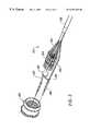
- FIG. 1is a perspective view of an electrosurgical system incorporating a power supply and an electrosurgical probe for tissue ablation, resection, incision, contraction and for vessel hemostasis according to the present invention
- FIG. 2is a side view of an electrosurgical probe according to the present invention.
- FIG. 3is an end view of the probe of FIG. 2;
- FIG. 4is a cross sectional view of the electrosurgical probe of FIG. 1;
- FIG. 5is an exploded view of a proximal portion of the electrosurgical probe
- FIGS. 6A-6Care cross-sectional views of the distal portions of three different embodiments of an electrosurgical probe according to the present invention.
- FIGS. 7A and 7Bare cross-sectional and end views, respectively, of yet another electrosurgical probe incorporating flattened electrode terminals
- FIG. 8illustrates an electrosurgical probe with a 90° distal bend and a lateral fluid lumen
- FIG. 9illustrates an electrosurgical system with a separate fluid delivery instrument according to the present invention
- FIG. 10is a detailed end view of an electrosurgical probe having an elongate, linear array of electrode terminals suitable for use in surgical cutting;
- FIG. 11is a detailed view of a single electrode terminal having a flattened end at its distal tip
- FIG. 12is a detailed view of a single electrode terminal having a pointed end at its distal tip
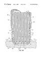
- FIG. 13is a perspective view of another embodiment of an electrosurgical probe for use in dermatology procedures
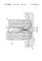
- FIGS. 14A-14Care exploded, isometric views of the probe of FIG. 13;
- FIG. 15is an end view of the distal tip of the probe, illustrating an electrode support with a plurality of electrode terminals
- FIG. 16illustrates the electrical connections and the electrode support of the handpiece in greater detail
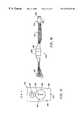
- FIG. 17is a perspective view of the distal portion of another electrosurgical probe according to the present invention.
- FIG. 18illustrates a method of removing a patellar ligament with the probe of FIG. 17 .
- tissue which may be treated by the system and method of the present inventioninclude, but are not limited to, prostate tissue and leiomyomas (fibroids) located within the uterus, gingival tissues and mucosal tissues located in the mouth, tumors, scar tissue, myocardial tissue, collagenous tissue within the eye or epidermal and dermal tissues on the surface of the skin.
- tissueswhich may be treated by the system and method of the present invention include, but are not limited to, prostate tissue and leiomyomas (fibroids) located within the uterus, gingival tissues and mucosal tissues located in the mouth, tumors, scar tissue, myocardial tissue, collagenous tissue within the eye or epidermal and dermal tissues on the surface of the skin.
- the present inventionis also useful for resecting tissue within accessible sites of the body that are suitable for electrode loop resection, such as the resection of prostate tissue, leiomyomas (fibroids) located within the uterus and other diseased tissue within the body.
- tissuewithin accessible sites of the body that are suitable for electrode loop resection, such as the resection of prostate tissue, leiomyomas (fibroids) located within the uterus and other diseased tissue within the body.
- the present inventionis also useful for procedures in the head and neck, such as the ear, mouth, pharynx, larynx, esophagus, nasal cavity and sinuses. These procedures may be performed through the mouth or nose using speculae or gags, or using endoscopic techniques, such as functional endoscopic sinus surgery (FESS).
- FESSfunctional endoscopic sinus surgery
- These proceduresmay include the removal of swollen tissue, chronically-diseased inflamed and hypertrophic mucus linings, polyps and/or neoplasms from the various anatomical sinuses of the skull, the turbinates and nasal passages, in the tonsil, adenoid, epi-glottic and supra-glottic regions, and salivary glands, submucus resection of the nasal septum, excision of diseased tissue and the like.
- the present inventionmay be useful for cutting, resection, ablation and/or hemostasis of tissue in procedures for treating snoring and obstructive sleep apnea (e.g., UPPP procedures), for gross tissue removal, such as tonsillectomies, adenoidectomies, tracheal stenosis and vocal cord polyps and lesions, or for the resection or ablation of facial tumors or tumors within the mouth and pharynx, such as glossectomies, laryngectomies, acoustic neuroma procedures and nasal ablation procedures.
- the present inventionis useful for procedures within the ear, such as stapedotomies, tympanostomies or the like.
- the present inventionmay also be useful for cosmetic and plastic surgery procedures in the head and neck.
- the present inventionis particularly useful for ablation and sculpting of cartilage tissue, such as the cartilage within the nose that is sculpted during rhinoplasty procedures.
- the present inventionmay also be employed for skin tissue removal and/or collagen shrinkage in the epidermis or dermis tissue in the head and neck, e.g., the removal of pigmentations, vascular lesions (e.g., leg veins), scars, tattoos, etc., and for other surgical procedures on the skin, such as tissue rejuvenation, cosmetic eye procedures (blepharoplasties), wrinkle removal, tightening muscles for facelifts or browlifts, hair removal and/or transplant procedures, etc.
- tissue rejuvenatione.g., cosmetic eye procedures (blepharoplasties), wrinkle removal, tightening muscles for facelifts or browlifts, hair removal and/or transplant procedures, etc.
- the remaining disclosurewill be directed specifically to the removal of ligaments within a joint during an arthroscopic procedure and to surgical procedures on the skin, but it will be appreciated that the system and method can be applied equally well to procedures involving other tissues of the body, as well as to other procedures including open procedures, intravascular procedures, urology, laparascopy, arthroscopy, thoracoscopy or other cardiac procedures, cosmetic surgery, orthopedics, gynecology, otorhinolaryngology, spinal and neurologic procedures, oncology and the like.
- high frequency (RF) electrical energyis applied to one or more electrode terminals in the presence of electrically conductive fluid to remove and/or modify the structure of tissue structures.
- the present inventionmay be used to: (1) volumetrically remove tissue or cartilage (i.e., ablate or effect molecular dissociation of the tissue structure); (2) cut or resect tissue; and/or (3) coagulate severed blood vessels.
- the tissue structuresare cut by volumetrically removing or ablating tissue along a cutting path.
- a high frequency voltage differenceis applied between one or more electrode terminal(s) and one or more return electrode(s) to develop high electric field intensities in the vicinity of the target tissue site.
- the high electric field intensitieslead to electric field induced molecular breakdown of target tissue through molecular dissociation (rather than thermal evaporation or carbonization).
- Applicantbelieves that the tissue structure is volumetrically removed through molecular disintegration of larger organic molecules into smaller molecules and/or atoms, such as hydrogen, oxides of carbon, hydrocarbons and nitrogen compounds. This molecular disintegration completely removes the tissue structure, as opposed to dehydrating the tissue material by the removal of liquid within the cells of the tissue, as is typically the case with electrosurgical desiccation and vaporization.
- the high electric field intensitiesmay be generated by applying a high frequency voltage that is sufficient to vaporize an electrically conducting fluid over at least a portion of the electrode terminal(s) in the region between the distal tip of the electrode terminal(s) and the target tissue.
- the electrically conductive fluidmay be a gas or liquid, such as isotonic saline, delivered to the target site, or a viscous fluid, such as a gel, that is located at the target site. In the latter embodiment, the electrode terminal(s) are submersed in the electrically conductive gel during the surgical procedure.
- the vapor layer or vaporized regionSince the vapor layer or vaporized region has a relatively high electrical impedance, it increases the voltage differential between the electrode terminal tip and the tissue and causes ionization within the vapor layer due to the presence of an ionizable species (e.g., sodium when isotonic saline is the electrically conducting fluid). This ionization, under optimal conditions, induces the discharge of energetic electrons and photons from the vapor layer and to the surface of the target tissue. This energy may be in the form of energetic photons (e.g., ultraviolet radiation), energetic particles (e.g., electrons) or a combination thereof.
- CoblationTMA more detailed description of this cold ablation phenomena, termed CoblationTM, can be found in commonly assigned U.S. Pat. No. 5,683,366 the complete disclosure of which is incorporated herein by reference.
- the present inventionapplies high frequency (RF) electrical energy in an electrically conducting fluid environment to remove (i.e., resect, cut or ablate) a tissue structure, and to seal transected vessels within the region of the target tissue.
- RFhigh frequency
- the present inventionis particularly useful for sealing larger arterial vessels, e.g., on the order of 1 mm or greater.
- a high frequency power supplyis provided having an ablation mode, wherein a first voltage is applied to an electrode terminal sufficient to effect molecular dissociation or disintegration of the tissue, and a coagulation mode, wherein a second, lower voltage is applied to an electrode terminal (either the same or a different electrode) sufficient to achieve hemostasis of severed vessels within the tissue.
- an electrosurgical probehaving one or more coagulation electrode(s) configured for sealing a severed vessel, such as an arterial vessel, and one or more electrode terminals configured for either contracting the collagen fibers within the tissue or removing (ablating) the tissue, e.g., by applying sufficient energy to the tissue to effect molecular dissociation.
- the coagulation electrode(s)may be configured such that a single voltage can be applied to coagulate with the coagulation electrode(s), and to ablate or contract with the electrode terminal(s).
- the power supplyis combined with the coagulation probe such that the coagulation electrode is used when the power supply is in the coagulation mode (low voltage), and the electrode terminal(s) are used when the power supply is in the ablation mode (higher voltage).
- one or more electrode terminalsare brought into close proximity to tissue at a target site, and the power supply is activated in the ablation mode such that sufficient voltage is applied between the electrode terminals and the return electrode to volumetrically remove the tissue through molecular dissociation, as described below.
- the power supplyis activated in the ablation mode such that sufficient voltage is applied between the electrode terminals and the return electrode to volumetrically remove the tissue through molecular dissociation, as described below.
- vessels within the tissuewill be severed. Smaller vessels will be automatically sealed with the system and method of the present invention. Larger vessels, and those with a higher flow rate, such as arterial vessels, may not be automatically sealed in the ablation mode. In these cases, the severed vessels may be sealed by activating a control (e.g., a foot pedal) to reduce the voltage of the power supply into the coagulation mode.
- a controle.g., a foot pedal
- the electrode terminalsmay be pressed against the severed vessel to provide sealing and/or coagulation of the vessel.
- a coagulation electrode located on the same or a different probemay be pressed against the severed vessel.
- the electrosurgical probewill comprise a shaft or a handpiece having a proximal end and a distal end which supports one or more electrode terminal(s).
- the shaft or handpiecemay assume a wide variety of configurations, with the primary purpose being to mechanically support the active electrode and permit the treating physician to manipulate the electrode from a proximal end of the shaft.
- the shaftmay be rigid or flexible, with flexible shafts optionally being combined with a generally rigid external tube for mechanical support. Flexible shafts may be combined with pull wires, shape memory actuators, and other known mechanisms for effecting selective deflection of the distal end of the shaft to facilitate positioning of the electrode array.
- the shaftwill usually include a plurality of wires or other conductive elements running axially therethrough to permit connection of the electrode array to a connector at the proximal end of the shaft. Specific shaft designs will be described in detail in connection with the figures hereinafter.
- the current flow path between the electrode terminal(s) and the return electrode(s)may be generated by submerging the tissue site in an electrical conducting fluid (e.g., within a viscous fluid, such as an electrically conductive gel) or by directing an electrically conducting fluid along a fluid path to the target site (i.e., a liquid, such as isotonic saline, or a gas, such as argon).
- an electrical conducting fluide.g., within a viscous fluid, such as an electrically conductive gel
- a fluid path to the target sitei.e., a liquid, such as isotonic saline, or a gas, such as argon.
- This latter methodis particularly effective in a dry environment (i.e., the tissue is not submerged in fluid) because the electrically conducting fluid provides a suitable current flow path from the electrode terminal to the return electrode.
- a more complete description of an exemplary method of directing electrically conducting fluid between the active and return electrodesis described in
- the system of the present inventionwill usually include a suction lumen in the probe, or on another instrument, for aspirating fluids from the target site.
- the present inventionmay use a single active electrode terminal or a plurality of electrodes distributed across a contact surface of a probe (e.g., in a linear fashion).
- the electrode arrayusually includes a plurality of independently current-limited and/or power-controlled electrode terminals to apply electrical energy selectively to the target tissue while limiting the unwanted application of electrical energy to the surrounding tissue and environment resulting from power dissipation into surrounding electrically conductive liquids, such as blood, normal saline, electrically conductive gel and the like.
- the electrode terminalsmay be independently current-limited by isolating the terminals from each other and connecting each terminal to a separate power source that is isolated from the other electrode terminals.
- the electrode terminalsmay be connected to each other at either the proximal or distal ends of the probe to form a single wire that couples to a power source.
- each individual electrode terminalis electrically insulated from all other electrode terminals within the probe and is connected to a power source which is isolated from each of the other electrode terminals in the array or to circuitry which limits or interrupts current flow to the electrode terminal when low resistivity material (e.g., blood, electrically conductive saline irrigant or electrically conductive gel) causes a lower impedance path between the return electrode and the individual electrode terminal.
- the isolated power sources for each individual electrode terminalmay be separate power supply circuits having internal impedance characteristics which limit power to the associated electrode terminal when a low impedance return path is encountered.
- the isolated power sourcemay be a user selectable constant current source.
- a single power sourcemay be connected to each of the electrode terminals through independently actuatable switches, or by independent current limiting elements, such as inductors, capacitors, resistors and/or combinations thereof.
- the current limiting elementsmay be provided in the probe, connectors, cable, controller or along the conductive path from the controller to the distal tip of the probe.
- the resistance and/or capacitancemay occur on the surface of the active electrode terminal(s) due to oxide layers which form selected electrode terminals (e.g., titanium or a resistive coating on the surface of metal, such as platinum).
- the tip region of the probemay comprise many independent electrode terminals designed to deliver electrical energy in the vicinity of the tip.
- the selective application of electrical energy to the conductive fluidis achieved by connecting each individual electrode terminal and the return electrode to a power source having independently controlled or current limited channels.
- the return electrode(s)may comprise a single tubular member of conductive material proximal to the electrode terminal(s) at the tip which also serves as a conduit for the supply of the electrically conducting fluid between the active and return electrodes.
- the probemay comprise an array of return electrodes at the distal tip of the probe (together with the active electrodes) to maintain the electric current at the tip.
- the application of high frequency voltage between the return electrode(s) and the electrode arrayresults in the generation of high electric field intensities at the distal tips of the electrode terminals with conduction of high frequency current from each individual electrode terminal to the return electrode.
- the current flow from each individual electrode terminal to the return electrode(s)is controlled by either active or passive means, or a combination thereof, to deliver electrical energy to the surrounding conductive fluid while minimizing energy delivery to surrounding (non-target) tissue.
- the application of a high frequency voltage between the return electrode(s) and the electrode terminal(s) for appropriate time intervalseffects cutting, removing, ablating, shaping, contracting or otherwise modifying the target tissue.
- the tissue volume over which energy is dissipatedi.e., a high current density exists
- the tissue volume over which energy is dissipatedmay be precisely controlled, for example, by the use of a multiplicity of small electrode terminals whose effective diameters or principal dimensions range from about 5 mm to 0.01 mm, preferably from about 2 mm to 0.05 mm, and more preferably from about 1 mm to 0.1 mm.
- Electrode areas for both circular and non-circular terminalswill have a contact area (per electrode terminal) below 25 mm 2 , preferably being in the range from 0.0001 mm 2 to 1 mm 2 , and more preferably from 0.005 mm 2 to 0.5 mm 2 .
- the circumscribed area of the electrode arrayis in the range from 0.25 mm 2 to 75 mm 2 , preferably from 0.5 mm 2 to 40 mm 2 , and will usually include at least two isolated electrode terminals, preferably at least five electrode terminals, often greater than 10 electrode terminals and even 50 or more electrode terminals, disposed over the distal contact surfaces on the shaft.
- the use of small diameter electrode terminalsincreases the electric field intensity and reduces the extent or depth of tissue heating as a consequence of the divergence of current flux lines which emanate from the exposed surface of each electrode terminal.
- the area of the tissue treatment surfacecan vary widely, and the tissue treatment surface can assume a variety of geometries, with particular areas and geometries being selected for specific applications.
- Active electrode surfacescan have areas in the range from 0.25 mm 2 to 75 mm 2 , usually being from about 0.5 mm 2 to 40 mm 2 .
- the geometriescan be planar, concave, convex, hemispherical, conical, linear “in-line” array or virtually any other regular or irregular shape.
- the active electrode(s) or electrode terminal(s)will be formed at the distal tip of the electrosurgical probe shaft, frequently being planar, disk-shaped, or hemispherical surfaces for use in reshaping procedures or being linear arrays for use in cutting.
- the active electrode(s)may be formed on lateral surfaces of the electrosurgical probe shaft (e.g., in the manner of a spatula), facilitating access to certain body structures in endoscopic procedures.
- the electrically conducting fluidshould have a threshold conductivity to provide a suitable conductive path between the return electrode(s) and the electrode terminal(s).
- the electrical conductivity of the fluid(in units of milliSiemans per centimeter or mS/cm) will usually be greater than 0.2 mS/cm, preferably will be greater than 2 mS/cm and more preferably greater than 10 mS/cm.
- the electrically conductive fluidis isotonic saline, which has a conductivity of about 17 mS/cm.
- the electrode support and the fluid outletmay be recessed from an outer surface of the probe or handpiece to confine the electrically conductive fluid to the region immediately surrounding the electrode support.
- the shaftmay be shaped so as to form a cavity around the electrode support and the fluid outlet. This helps to assure that the electrically conductive fluid will remain in contact with the electrode terminal(s) and the return electrode(s) to maintain the conductive path therebetween. In addition, this will help to maintain a vapor or plasma layer between the electrode terminal(s) and the tissue at the treatment site throughout the procedure, which reduces the thermal damage that might otherwise occur if the vapor layer were extinguished due to a lack of conductive fluid. Provision of the electrically conductive fluid around the target site also helps to maintain the tissue temperature at desired levels.
- the voltage applied between the return electrode(s) and the electrode arraywill be at high or radio frequency, typically between about 5 kHz and 20 MHz, usually being between about 30 kHz and 2.5 MHz, preferably being between about 50 kHz and 500 kHz, more preferably less than 350 kHz, and most preferably between about 100 kHz and 200 kHz.
- the RMS (root mean square) voltage appliedwill usually be in the range from about 5 volts to 1000 volts, preferably being in the range from about 10 volts to 500 volts depending on the electrode terminal size, the operating frequency and the operation mode of the particular procedure or desired effect on the tissue (i.e., contraction, coagulation or ablation).
- the peak-to-peak voltagewill be in the range of 10 to 2000 volts, preferably in the range of 20 to 1200 volts and more preferably in the range of about 40 to 800 volts (again, depending on the electrode size, the operating frequency and the operation mode).
- the voltageis usually delivered in a series of voltage pulses or alternating current of time varying voltage amplitude with a sufficiently high frequency (e.g., on the order of 5 kHz to 20 MHz) such that the voltage is effectively applied continuously (as compared with e.g., lasers claiming small depths of necrosis, which are generally pulsed about 10 to 20 Hz).
- the duty cyclei.e., cumulative time in any one-second interval that energy is applied
- the preferred power source of the present inventiondelivers a high frequency current selectable to generate average power levels ranging from several milliwatts to tens of watts per electrode, depending on the volume of target tissue being heated, and/or the maximum allowed temperature selected for the probe tip.
- the power sourceallows the user to select the voltage level according to the specific requirements of a particular arthroscopic procedure, open surgery or other endoscopic surgery procedure.
- a description of a suitable power sourcecan be found in U.S. Provisional Patent Application No. 60/062,997, filed Oct. 23, 1997, the complete disclosure of which has been incorporated herein by reference.
- the power sourcemay be current limited or otherwise controlled so that undesired heating of the target tissue or surrounding (non-target) tissue does not occur.
- current limiting inductorsare placed in series with each independent electrode terminal, where the inductance of the inductor is in the range of 10 uH to 50,000 uH, depending on the electrical properties of the target tissue, the desired tissue heating rate and the operating frequency.
- capacitor-inductor (LC) circuit structuresmay be employed, as described previously in co-pending PCT application No. PCT/US94/05168, the complete disclosure of which is incorporated herein by reference. Additionally, current limiting resistors may be selected.
- these resistorswill have a large positive temperature coefficient of resistance so that, as the current level begins to rise for any individual electrode terminal in contact with a low resistance medium (e.g., saline irrigant or conductive gel), the resistance of the current limiting resistor increases significantly, thereby minimizing the power delivery from said electrode terminal into the low resistance medium (e.g., saline irrigant or conductive gel).
- a low resistance mediume.g., saline irrigant or conductive gel
- the inventionis not limited to electrically isolated electrode terminals, or even to a plurality of electrode terminals.
- the array of active electrode terminalsmay be connected to a single lead that extends through the probe shaft to a power source of high frequency current.
- the probemay incorporate a single electrode that extends directly through the probe shaft or is connected to a single lead that extends to the power source.
- the active electrodemay have a screwdriver or conical shape as described below, or a ball shape (e.g., for tissue vaporization and desiccation), a twizzle shape (for vaporization and needle-like cutting), a spring shape (for rapid tissue debulking and desiccation), a twisted metal shape, an annular or solid tube shape or the like.
- the electrodemay comprise a plurality of filaments, a rigid or flexible brush electrode (for debulking a tumor, such as a fibroid, bladder tumor or a prostate adenoma), a side-effect brush electrode on a lateral surface of the shaft, a coiled electrode or the like.
- the probecomprises a single active electrode terminal that extends from an insulating member, e.g., ceramic, at the distal end of the probe.
- the insulating memberis preferably a tubular structure that separates the active electrode terminal from a tubular or annular return electrode positioned proximal to the insulating member and the active electrode.
- Electrosurgical system 11generally comprises an electrosurgical handpiece or probe 10 connected to a power supply 28 for providing high frequency voltage to a target site and a fluid source 21 for supplying electrically conducting fluid 50 to probe 10 .
- electrosurgical system 11may include an endoscope (not shown) with a fiber optic head light for viewing the surgical site, particularly in sinus procedures or procedures in the ear or the back of the mouth.
- the endoscopemay be integral with probe 10 , or it may be part of a separate instrument.
- the system 11may also include a vacuum source (not shown) for coupling to a suction lumen or tube 211 (see FIG. 2) in the probe 10 for aspirating the target site.
- probe 10generally includes a proximal handle 19 and an elongate shaft 18 having a linear array 12 of electrode terminals 58 at its distal end.
- a connecting cable 34has a connector 26 for electrically coupling the electrode terminals 58 to power supply 28 .
- the electrode terminals 58are electrically isolated from each other and each of the terminals 58 is connected to an active or passive control network within power supply 28 by means of a plurality of individually insulated conductors (not shown).
- a fluid supply tube 15is connected to a fluid tube 14 of probe 10 for supplying electrically conducting fluid 50 to the target site.
- Power supply 28has an operator controllable voltage level adjustment 30 to change the applied voltage level, which is observable at a voltage level display 32 .
- Power supply 28also includes first, second and third foot pedals 37 , 38 , 39 and a cable 36 which is removably coupled to power supply 28 .
- the foot pedals 37 , 38 , 39allow the surgeon to remotely adjust the energy level applied to electrode terminals 58 .
- first foot pedal 37is used to place the power supply into the “ablation” mode and second foot pedal 38 places power supply 28 into the “coagulation” mode.
- the third foot pedal 39allows the user to adjust the voltage level within the “ablation” mode.
- a sufficient voltageis applied to the electrode terminals to establish the requisite conditions for molecular dissociation of the tissue (i.e., vaporizing a portion of the electrically conductive fluid, ionizing charged particles within the vapor layer and accelerating these charged particles against the tissue).
- the requisite voltage level for ablationwill vary depending on the number, size, shape and spacing of the electrodes, the distance in which the electrodes extend from the support member, etc.
- the power supply 28applies a low enough voltage to the electrode terminals (or the coagulation electrode) to avoid vaporization of the electrically conductive fluid and subsequent molecular dissociation of the tissue.
- the surgeonmay automatically toggle the power supply between the ablation and coagulation modes by alternatively stepping on foot pedals 37 , 38 , respectively. This allows the surgeon to quickly move between coagulation and ablation in situ, without having to remove his/her concentration from the surgical field or without having to request an assistant to switch the power supply.
- the probetypically will simultaneously seal and/or coagulation small severed vessels within the tissue.
- FIGS. 2-5illustrate an exemplary electrosurgical probe 20 constructed according to the principles of the present invention.
- Electrosurgical probe 20is particularly useful for cutting tissue in the region of the head and neck, e.g., the ear, nose and throat, of a patient.
- probe 20or a similar device, may be used in a variety of applications, as discussed above.
- probe 20generally includes an elongated shaft 100 which may be flexible or rigid, a handle 204 coupled to the proximal end of shaft 100 and an electrode support member 102 coupled to the distal end of shaft 100 .
- Shaft 100preferably comprises a plastic material that is easily molded into the shape shown in FIG. 3 .
- shaft 100comprises an electrically conducting material, usually metal, which is selected from the group comprising tungsten, stainless steel alloys, platinum or its alloys, titanium or its alloys, molybdenum or its alloys, and nickel or its alloys.
- shaft 100includes an electrically insulating jacket 108 , which is typically formed as one or more electrically insulating sheaths or coatings, such as polytetrafluoroethylene, polyimide, and the like. The provision of the electrically insulating jacket over the shaft prevents direct electrical contact between these metal elements and any adjacent body structure or the surgeon. Such direct electrical contact between a body structure (e.g., tendon) and an exposed electrode could result in unwanted heating and necrosis of the structure at the point of contact causing necrosis.
- a body structuree.g., tendon
- Handle 204typically comprises a plastic material that is easily molded into a suitable shape for handling by the surgeon. Handle 204 defines an inner cavity (not shown) that houses the electrical connections 250 (FIG. 5 ), and provides a suitable interface for connection to an electrical connecting cable 22 (see FIG. 2 ). Electrode support member 102 extends from the distal end of shaft 100 (usually about 1 to 20 mm), and provides support for a plurality of electrically isolated electrode terminals 104 (see FIG. 4 B). As shown in FIG. 2, a fluid tube 233 extends through an opening in handle 204 , and includes a connector 235 for connection to a fluid supply source, for supplying electrically conductive fluid to the target site.
- Fluid tube 233is coupled to a distal fluid tube 239 that extends along the outer surface of shaft 100 to an opening 237 at the distal end of the probe 20 , as discussed in detail below.
- fluid tube 233may extend through a single lumen (not shown) in shaft 100 , or it may be coupled to a plurality of lumens (also not shown) that extend through shaft 100 to a plurality of openings at its distal end.
- Probe 20may also include a valve 17 (FIG. 2) or equivalent structure for controlling the flow rate of the electrically conducting fluid to the target site.
- electrode support member 102has a substantially planar tissue treatment surface 212 and comprises a suitable insulating material (e.g., ceramic or glass material, such as alumina, zirconia and the like) which could be formed at the time of manufacture in a flat, hemispherical or other shape according to the requirements of a particular procedure.
- a suitable insulating materiale.g., ceramic or glass material, such as alumina, zirconia and the like
- the preferred support member materialis alumina, available from Kyocera Industrial Ceramics Corporation, Elkgrove, Ill., because of its high thermal conductivity, good electrically insulative properties, high flexural modulus, resistance to carbon tracking, biocompatibility, and high melting point.
- the support member 102is adhesively joined to a tubular support member (not shown) that extends most or all of the distance between support member 102 and the proximal end of probe 20 .
- the tubular memberpreferably comprises an electrically insulating material, such as an epoxy or silicone-based material.
- electrode terminals 104extend through pre-formed openings in the support member 102 so that they protrude above tissue treatment surface 212 by the desired distance.
- the electrodesare then bonded to the tissue treatment surface 212 of support member 102 , typically by an inorganic sealing material.
- the sealing materialis selected to provide effective electrical insulation, and good adhesion to both the alumina member 102 and the platinum or titanium electrode terminals 104 .
- the sealing materialadditionally should have a compatible thermal expansion coefficient and a melting point well below that of platinum or titanium and alumina or zirconia, typically being a glass or glass ceramic
- probe 20includes a return electrode 112 for completing the current path between electrode terminals 104 and a high frequency power supply 28 (see FIG. 1 ).
- return electrode 112preferably comprises an annular conductive band coupled to the distal end of shaft 100 slightly proximal to tissue treatment surface 212 of electrode support member 102 , typically about 0.5 to 10 mm and more preferably about 1 to 10 mm.
- Return electrode 112is coupled to a connector 258 that extends to the proximal end of probe 10 , where it is suitably connected to power supply 28 (FIG. 1 ).
- return electrode 112is not directly connected to electrode terminals 104 .
- electrically conducting fluide.g., isotonic saline
- the electrically conducting fluidis delivered through an external fluid tube 239 to opening 237 , as described above.
- the fluidmay be delivered by a fluid delivery element (not shown) that is separate from probe 20 .
- the joint cavityis typically flooded with isotonic saline and the probe 20 will be introduced into this flooded cavity. Electrically conducting fluid will be continually resupplied with a separate instrument to maintain the conduction path between return electrode 112 and electrode terminals 104 .
- the fluid pathmay be formed in probe 20 by, for example, an inner lumen or an annular gap between the return electrode and a tubular support member within shaft 100 (not shown).
- This annular gapmay be formed near the perimeter of the shaft 100 such that the electrically conducting fluid tends to flow radially inward towards the target site, or it may be formed towards the center of shaft 100 so that the fluid flows radially outward.
- a fluid sourcee.g., a bag of fluid elevated above the surgical site or having a pumping device
- a fluid supply tube(not shown) that may or may not have a controllable valve.
- the electrically isolated electrode terminals 104are preferably spaced from each other and aligned to form a linear array 105 of electrodes for cutting a substantially linear incision in the tissue.
- the tissue treatment surface and individual electrode terminals 104will usually have dimensions within the ranges set forth above.
- Electrode terminals 104preferably have a distal edge 107 to increase the electric field intensities around terminals 104 , and to facilitate cutting of tissue.
- electrode terminals 104have a screwdriver shape in the representative embodiment of FIGS. 2-5.
- the tissue treatment surface 212has a circular cross-sectional shape with a diameter in the range of about 1 mm to 30 mm, usually about 2 to 20 mm.
- the individual electrode terminals 104preferably extend outward from tissue treatment surface 212 by a distance of about 0.1 to 8 mm, usually about 1 to 4 mm. Applicant has found that this configuration increases the high electric field intensities and associated current densities around electrode terminals 104 to facilitate the ablation of tissue as described in detail above.
- the probemay include a suction or aspiration lumen 213 (see FIG. 2) within shaft 100 and a suction tube 211 (FIG. 2) for aspirating tissue, fluids and/or gases from the target site.
- the electrically conductive fluidgenerally flows from opening 237 of fluid tube 239 radially inward and then back through one or more openings (not shown) in support member 102 .
- Aspirating the electrically conductive fluid during surgeryallows the surgeon to see the target site, and it prevents the fluid from flowing into the patient's body, e.g., into the spine, the abdomen or the thoracic cavity. This aspiration should be controlled, however, so that the conductive fluid maintains a conductive path between the active electrode terminal(s) and the return electrode.
- the probe 20will also include one or more aspiration electrode(s) (not shown) coupled to the aspiration lumen for inhibiting clogging during aspiration of tissue fragments from the surgical site.
- aspiration electrode(s)coupled to the aspiration lumen for inhibiting clogging during aspiration of tissue fragments from the surgical site.
- FIG. 5illustrates the electrical connections 250 within handle 204 for coupling electrode terminals 104 and return electrode 112 to the power supply 28 .
- a plurality of wires 252extend through shaft 100 to couple terminals 104 to a plurality of pins 254 , which are plugged into a connector block 256 for coupling to a connecting cable 22 (FIG. 1 ).
- return electrode 112is coupled to connector block 256 via a wire 258 and a plug 260 .
- the probe 90further includes an identification element that is characteristic of the particular electrode assembly so that the same power supply 28 can be used for different electrosurgical operations.
- the probe 90includes a voltage reduction element or a voltage reduction circuit for reducing the voltage applied between the electrode terminals 104 and the return electrode 112 .
- the voltage reduction elementserves to reduce the voltage applied by the power supply so that the voltage between the electrode terminals and the return electrode is low enough to avoid excessive power dissipation into the electrically conducting medium and/or ablation of the soft tissue at the target site.
- the voltage reduction elementprimarily allows the electrosurgical probe 90 to be compatible with other ArthroCare generators that are adapted to apply higher voltages for ablation or vaporization of tissue.
- the voltage reduction elementwill serve to reduce a voltage of about 100 to 135 volts rms (which is a setting of 1 on the ArthroCare Model 970 and 980 (i.e., 2000) Generators) to about 45 to 60 volts rms, which is a suitable voltage for contraction of tissue without ablation (e.g., molecular dissociation) of the tissue.
- the probewill typically not require a voltage reduction element.
- the probemay include a voltage increasing element or circuit, if desired.
- the voltage reduction elementis a dropping capacitor 262 which has first leg 264 coupled to the return electrode wire 258 and a second leg 266 coupled to connector block 256 .
- the capacitormay be located in other places within the system, such as in, or distributed along the length of, the cable, the generator, the connector, etc.
- other voltage reduction elementssuch as diodes, transistors, inductors, resistors, capacitors or combinations thereof, may be used in conjunction with the present invention.
- the probe 90may include a coded resistor (not shown) that is constructed to lower the voltage applied between return electrode 112 and electrode terminals 104 to a suitable level for contraction of tissue.
- electrical circuitsmay be employed for this purpose.
- the cable 22 that couples the power supply 10 to the probe 90may be used as a voltage reduction element.
- the cablehas an inherent capacitance that can be used to reduce the power supply voltage if the cable is placed into the electrical circuit between the power supply, the electrode terminals and the return electrode.
- the cable 22may be used alone, or in combination with one of the voltage reduction elements discussed above, e.g., a capacitor.
- the present inventioncan be used with a power supply that is adapted to apply a voltage within the selected range for treatment of tissue.
- a voltage reduction element or circuitrymay not be desired.
- FIGS. 6A-6Cschematically illustrate the distal portion of three different embodiments of probe 90 according to the present invention.
- electrode terminals 104are anchored in a support matrix 102 of suitable insulating material (e.g., ceramic or glass material, such as alumina, zirconia and the like) which could be formed at the time of manufacture in a flat, hemispherical or other shape according to the requirements of a particular procedure.
- suitable insulating materiale.g., ceramic or glass material, such as alumina, zirconia and the like
- the preferred support matrix materialis alumina, available from Kyocera Industrial Ceramics Corporation, Elkgrove, Ill., because of its high thermal conductivity, good electrically insulative properties, high flexural modulus, resistance to carbon tracking, biocompatibility, and high melting point.
- the support matrix 102is adhesively joined to a tubular support member 78 that extends most or all of the distance between matrix 102 and the proximal end of probe 90 .
- Tubular member 78preferably comprises an electrically insulating material, such as an epoxy or silicone-based material.
- electrode terminals 104extend through pre-formed openings in the support matrix 102 so that they protrude above tissue treatment surface 212 by the desired distance.
- the electrodesare then bonded to the tissue treatment surface 212 of support matrix 102 , typically by an inorganic sealing material 80 .
- Sealing material 80is selected to provide effective electrical insulation, and good adhesion to both the alumina matrix 102 and the platinum or titanium electrode terminals.
- Sealing material 80additionally should have a compatible thermal expansion coefficient and a melting point well below that of platinum or titanium and alumina or zirconia, typically being a glass or glass ceramic.
- return electrode 112comprises an annular member positioned around the exterior of shaft 100 of probe 90 .
- Return electrode 112may fully or partially circumscribe tubular support member 78 to form an annular gap 54 therebetween for flow of electrically conducting liquid 50 therethrough, as discussed below.
- Gap 54preferably has a width in the range of 0.25 mm to 4 mm.
- probemay include a plurality of longitudinal ribs between support member 78 and return electrode 112 to form a plurality of fluid lumens extending along the perimeter of shaft 100 . In this embodiment, the plurality of lumens will extend to a plurality of openings.
- Return electrode 112is disposed within an electrically insulative jacket 18 , which is typically formed as one or more electrically insulative sheaths or coatings, such as polytetrafluoroethylene, polyamide, and the like.
- the provision of the electrically insulative jacket 18 over return electrode 112prevents direct electrical contact between return electrode 56 and any adjacent body structure. Such direct electrical contact between a body structure (e.g., tendon) and an exposed electrode member 112 could result in unwanted heating and necrosis of the structure at the point of contact causing necrosis.
- return electrode 112is not directly connected to electrode terminals 104 .
- electrically conducting liquid 50e.g., isotonic saline
- Fluid path 83is formed by annular gap 54 between outer return electrode 112 and tubular support member. The electrically conducting liquid 50 flowing through fluid path 83 provides a pathway for electrical current flow between electrode terminals 104 and return electrode 112 , as illustrated by the current flux lines 60 in FIG. 6 A.
- FIG. 6Billustrates another alternative embodiment of electrosurgical probe 90 which has a return electrode 112 positioned within tubular member 78 .
- Return electrode 112is preferably a tubular member defining an inner lumen 57 for allowing electrically conducting liquid 50 (e.g., isotonic saline) to flow therethrough in electrical contact with return electrode 112 .
- electrically conducting liquid 50e.g., isotonic saline
- a voltage differenceis applied between electrode terminals 104 and return electrode 112 resulting in electrical current flow through the electrically conducting liquid 50 as shown by current flux lines 60 (FIG. 3 ).
- tissue 52becomes ablated or transected in zone 88 .
- FIG. 6Cillustrates another embodiment of probe 90 that is a combination of the embodiments in FIGS. 6A and 6B. As shown, this probe includes both an inner lumen 57 and an outer gap or plurality of outer lumens 54 for flow of electrically conductive fluid.
- the return electrode 112may be positioned within tubular member 78 as in FIG. 6B, outside of tubular member 78 as in FIG. 6A, or in both locations.
- FIG. 8illustrates another embodiment of probe 90 where the distal portion of shaft 100 is bent so that electrode terminals extend transversely to the shaft.
- the distal portion of shaft 100is perpendicular to the rest of the shaft so that tissue treatment surface 212 is generally parallel to the shaft axis.
- return electrode 112is mounted to the outer surface of shaft 100 and is covered with an electrically insulating jacket 18 .
- the electrically conducting fluid 50flows along flow path 83 through return electrode 112 and exits the distal end of electrode 112 at a point proximal of tissue treatment surface 212 .
- the fluidis directed exterior of shaft to surface 212 to create a return current path from electrode terminals 104 , through the fluid 50 , to return electrode 12 , as shown by current flux lines 60 .
- FIG. 9illustrates another embodiment of the invention where electrosurgical system 11 further includes a liquid supply instrument 64 for supplying electrically conducting fluid 50 between electrode terminals 104 and return electrode 112 .
- Liquid supply instrument 64comprises an inner tubular member or return electrode 112 surrounded by an electrically insulating jacket 18 .
- Return electrode 112defines an inner passage 83 for flow of fluid 50 .
- the distal portion of instrument 64is preferably bent so that liquid 50 is discharged at an angle with respect to instrument 64 . This allows the surgical team to position liquid supply instrument 64 adjacent tissue treatment surface 212 with the proximal portion of supply instrument 64 oriented at a similar angle to probe 90 .
- an alternative probe 90includes a pair of electrodes 105 a , 105 b mounted to the distal end of shaft 100 . Electrodes 105 a , 105 b are electrically connected to power supply as described above and preferably have tips 107 a , 107 b with a screwdriver shape.
- the screwdriver shapeprovides a greater amount of “edges” to electrodes 105 a , 105 b , to increase the electric field intensity and current density at the edges and thereby improve the cutting ability as well as the ability to limit bleeding from the incised tissue (i.e., hemostasis).
- FIG. 10illustrates yet another embodiment designed for cutting of body structures.
- the electrode terminals 104are arranged in a linear or columnar array of one of more closely spaced columns so that as the electrodes 104 are moved along the longer axis (denoted by arrow 160 in FIG. 10 ), the current flux lines are narrowly confined at the tip of the electrode terminals 104 and result in a cutting effect in the body structure being treated.
- the current flux lines 60 emanating from the electrode terminals 104pass through the electrically conducting liquid to the return electrode structure 112 located proximal to the probe tip.
- FIGS. 11 and 12alternative geometries are shown for the electrode terminals 104 . These alternative electrode geometries allow the electrical current densities emanating from the electrode terminals 104 to be concentrated to achieve an increased ablation rate and/or a more concentrated ablation effect due to the fact that sharper edges (i.e., regions of smaller radii of curvature) result in higher current densities.
- FIG. 11illustrates a flattened extension of a round wire electrode terminal 104 which results in higher current densities at the edges 180 .
- FIG. 12shows another example in FIG. 12 in which the electrode terminal 104 is formed into a cone shaped point 182 resulting in higher current densities at the tip of the cone.
- FIGS. 13-16illustrate an exemplary electrosurgical probe 300 or “dermal scalpel” for cutting and removing structures from the outer surface of the skin, such as lesions, scars, etc.
- Probe 300comprises a shaft or disposable tip 313 removably coupled to a proximal handle 312 , and an electrically insulating electrode support member 370 extending from tip 313 for supporting a plurality of electrode terminals 358 (see FIGS. 13 and 16 ).
- Tip 313 and handle 312typically comprise a plastic material that is easily molded into a suitable shape for handling by the surgeon.
- handle 312defines an inner cavity 372 that houses the electrical connections 374 , and provides a suitable interface for connection to electrical connecting cable 34 (see FIG. 1 ).
- handle 312is constructed of a steam autoclavable plastic or metal (e.g., polyethylether keytone, or a stable metal alloy containing aluminum and/or zine. so that it can be re-used by sterilizing handle 312 between surgical procedures.
- a steam autoclavable plastic or metale.g., polyethylether keytone, or a stable metal alloy containing aluminum and/or zine.
- High service temperature materialsare preferred, such as a silicone cable jacket and a poly-ether-imide handpiece or ULTEM® that can withstand a repeated exposure to high temperatures.
- tip 313preferably comprises first and second housing halves 500 , 502 that snap fit together, and form a recess 404 therebetween for holding electrode support member 370 within the tip 313 .
- Electrode support member 370extends from the distal end of tip 313 (usually about 0.5 to 20 mm), and provides support for a plurality of electrically isolated electrode terminals 358 and one or more return electrodes 400 (see FIG. 16 ).
- electrode support member 370may be recessed from the distal end of tip 313 to help confine the electrically conductive fluid around the electrode terminals 358 during the surgical procedure, as discussed above.
- Electrode support member 370has a substantially planar tissue treatment surface 380 that is usually disposed at an angle of about 10 to 90 degrees relative to the longitudinal axis of handle 312 to facilitate handling by the surgeon. In the exemplary embodiment, this function is accomplished by orienting tip 313 at an acute angle relative to the longitudinal axis of handle 312 .
- probe 310includes a single annular return electrode 400 for completing the current path between electrode terminals 358 and power supply 328 (see FIG. 1 ).
- return electrode 400preferably has a fluid contact surface slightly proximal to tissue treatment surface 380 , typically about 0.1 to 2 mm, preferably about 0.2 to 1 mm.
- Return electrode 400is coupled to a connector 404 that extends to the proximal end of handle 313 , where it is suitably connected to power supply 28 (FIG. 1 ).
- tip 313further includes a proximal hub 506 for supporting a male electrical connector 508 that holds a plurality of wires 510 each coupled to one of the electrode terminals 358 and the return electrode 400 on support member 370 .
- a female connector 520 housed within handle 312is removably coupled to male connector 508 , and a plurality of wires 522 extend from female connector 520 through a strain relief 524 to cable 334 . Both sets of wires 510 , 522 are insulated to prevent shorting in the event of fluid ingress into the probe 310 .
- Probe 310will preferably also include an identification element, such as a coded resistor (not shown), for programming a particular voltage output range and mode of operation for the power supply. This allows the power supply to be employed with a variety of different probes for a variety of different applications.
- an identification elementsuch as a coded resistor (not shown), for programming a particular voltage output range and mode of operation for the power supply. This allows the power supply to be employed with a variety of different probes for a variety of different applications.
- probe 310includes a fluid tube 410 (FIG. 14) for delivering electrically conductive fluid to the target site.
- Fluid tube 410is sized to extend through a groove 414 in handle 313 and through an inner cavity 412 in tip 312 to a distal opening 414 (FIG. 15) located adjacent electrode support member 370 .
- Tube 410extends all the way through inner cavity 412 to opening 414 to eliminate any possible fluid ingress into cavity 412 .
- fluid tube 410includes a proximal connector 412 for coupling to an electrically conductive fluid source 321 .
- Probe 310will also include a valve or equivalent structure for controlling the flow rate of the electrically conducting fluid to the target site.
- handle 312comprises a main body 430 coupled between distal hub 418 and strain relief 420 , and a rotatable sleeve 416 around main body 430 .
- Distal hub 418has an opening 419 for receiving proximal hub 506 of tip 313 for removably coupling the tip 313 to the handle 312 .
- Sleeve 416is rotatably coupled to strain relief 420 and distal hub 418 to provide a valve structure for fluid tube 410 . As shown in FIG.
- fluid tube 410extends through groove 414 from strain relief 420 , through main body 430 and distal hub 420 to tip 313 .
- Rotation of sleeve 416will impede, and eventually obstruct, the flow of fluid through tube 410 .
- this fluid controlmay be provided by a variety of other input and valve devices, such as switches, buttons, etc.
- the fluid pathmay be directly formed in probe 310 by, for example, a central inner lumen or an annular gap (not shown) within the handle and the tip.
- This inner lumenmay be formed near the perimeter of the probe 310 such that the electrically conducting fluid tends to flow radially inward towards the target site, or it may be formed towards the center of probe 310 so that the fluid flows radially outward.
- the electrically conducting fluidmay be delivered from a fluid delivery element (not shown) that is separate from probe 310 . In arthroscopic surgery, for example, the body cavity will be flooded with isotonic saline and the probe 310 will be introduced into this flooded cavity.
- electrode terminals 358are spaced apart over tissue treatment surface 380 of electrode support member 370 , preferably in a linear array.
- three electrode terminals 358are arranged in a linear array extending distally from surface 380 .
- Electrode terminals 358will usually extend a distance of about 0.5 to 20 mm from tissue treatment surface 380 , preferably about 1 to 5 mm. Applicant has found that this configuration increases the electric field intensities and associated current densities at the distal edges of electrode terminals 358 , which increases the rate of tissue cutting.
- the tissue treatment surface 380has a circular cross-sectional shape with a diameter in the range of about 0.5 mm to 20 mm (preferably about 2 to 10 mm).
- the individual electrode terminals 358preferably taper outward as shown, or they may form a distal edge, such as the electrodes shown in FIGS. 8A and 11.
- Electrode support member 370preferably comprises a multilayer substrate comprising a suitable high temperature, electrically insulating material, such as ceramic.
- the multilayer substrateis a thin or thick-film hybrid having conductive strips that are adhered to the ceramic wafer layers (e.g., thick-film printed and fired onto or plated onto the ceramic wafers).
- the conductive stripstypically comprise tungsten, gold, nickel, silver, platinum or equivalent materials.
- the conductive stripscomprise tungsten, and they are co-fired together with the wafer layers to form an integral package.
- the conductive stripsare coupled to external wire connectors by holes or vias that are drilled through the ceramic layers, and plated or otherwise covered with conductive material.
- an electrosurgical probe 90comprises a shaft 100 and at least two electrode terminals 104 extending from a support matrix 102 at the distal end of the shaft.
- the electrode terminals 104preferably define a distal edge 600 for cutting an incision in tissue.
- the edges 600 of the electrode terminals 104are substantially parallel with each other and usually spaced a distance of about 4 to 15 mm, preferably about 8-10 mm.
- the edges 600extend from the distal end of support matrix 102 by a distance of about 0.5 to 10 mm, preferably about 2 to 5 mm.
- probe 90will include a return electrode 112 spaced proximally from the electrode terminals 104 .
- the return electrode 112may be one of the electrode terminals 104 , or it may be a dispersive pad located on an external surface of the patient's body.
- the probe 90 of FIG. 17is particularly useful for removing a ligament from a joint, such as the patellar ligament 602 (or one of the cruciate ligaments) from the knee cavity 604 .
- the patellar ligament 602extends from the patella 606 down to the tibia 608 .
- the patellar ligament 602is separated from the surrounding tissue 610 (typically with a scalpel) on either side of the ligament. The surgeon then severs the ligament 602 at the upper and lower portions thereof and removes the ligament from the patient's knee.
- One of the disadvantages with conventional scalpelsis that they produce excessive bleeding, which obstructs visualization of the surgical site. In addition, the scalpels damage the surrounding tissue, which increases the patient's recovery time.
- the distal end portion of probe 90(FIG. 17) is introduced into the knee cavity, and electrode terminals 104 are positioned on either side of patellar ligament 602 (FIG. 18 ).
- a high frequency voltage differenceis applied between electrode terminals 104 and return electrode 112 and the probe 90 is translated along the length of the ligament 602 to separate the ligament from the surrounding tissue 610 .
- the sharp edges of electrode terminals 104facilitate cutting through tissue.
- the high frequency voltageis sufficient to convert the electrically conductive fluid (not shown) between the target tissue and electrode terminal(s) 104 into an ionized vapor layer or plasma (not shown).
- the applied voltage difference between electrode terminal(s) 104 and the target tissuei.e., the voltage gradient across the plasma layer
- charged particles in the plasmaviz., electrons
- these charged particlesgain sufficient energy to cause dissociation of the molecular bonds within tissue structures.
- This molecular dissociationis accompanied by the volumetric removal (i.e., ablative sublimation) of tissue and the production of low molecular weight gases, such as oxygen, nitrogen, carbon dioxide, hydrogen and methane.
- the short range of the accelerated charged particles within the tissueconfines the molecular dissociation process to the surface layer to minimize damage and necrosis to the underlying tissue and the adjacent ligament 602 .
- the gasesmay be aspirated through a suction tube (not shown) in the probe to a vacuum source.
- excess electrically conductive fluid, and other fluidse.g., blood
- the residual heat generated by the current flux linestypically less than 150° C.
- the surgeonmay switch the power supply 28 into the coagulation mode by lowering the voltage to a level below the threshold for fluid vaporization, as discussed above. This simultaneous hemostasis results in less bleeding and facilitates the surgeon's ability to perform the procedure.
Landscapes
- Health & Medical Sciences (AREA)
- Engineering & Computer Science (AREA)
- Life Sciences & Earth Sciences (AREA)
- Surgery (AREA)
- Biomedical Technology (AREA)
- Heart & Thoracic Surgery (AREA)
- Nuclear Medicine, Radiotherapy & Molecular Imaging (AREA)
- Otolaryngology (AREA)
- Physics & Mathematics (AREA)
- Veterinary Medicine (AREA)
- Public Health (AREA)
- Plasma & Fusion (AREA)
- Medical Informatics (AREA)
- Molecular Biology (AREA)
- Animal Behavior & Ethology (AREA)
- General Health & Medical Sciences (AREA)
- Neurology (AREA)
- Neurosurgery (AREA)
- Cardiology (AREA)
- Surgical Instruments (AREA)
Abstract
Description
Claims (38)
Priority Applications (6)
| Application Number | Priority Date | Filing Date | Title |
|---|---|---|---|
| US09/041,934US6391025B1 (en) | 1993-05-10 | 1998-03-13 | Electrosurgical scalpel and methods for tissue cutting |
| US09/771,299US6915806B2 (en) | 1993-05-10 | 2001-01-25 | Method for harvesting graft vessel |
| US09/780,745US6770071B2 (en) | 1995-06-07 | 2001-02-09 | Bladed electrosurgical probe |
| US09/839,427US6974453B2 (en) | 1993-05-10 | 2001-04-20 | Dual mode electrosurgical clamping probe and related methods |
| US10/057,412US6837887B2 (en) | 1995-06-07 | 2002-01-25 | Articulated electrosurgical probe and methods |
| US10/082,017US6837888B2 (en) | 1995-06-07 | 2002-02-25 | Electrosurgical probe with movable return electrode and methods related thereto |
Applications Claiming Priority (4)
| Application Number | Priority Date | Filing Date | Title |
|---|---|---|---|
| US5968193A | 1993-05-10 | 1993-05-10 | |
| US08/485,219US5697281A (en) | 1991-10-09 | 1995-06-07 | System and method for electrosurgical cutting and ablation |
| US08/990,374US6109268A (en) | 1995-06-07 | 1997-12-15 | Systems and methods for electrosurgical endoscopic sinus surgery |
| US09/041,934US6391025B1 (en) | 1993-05-10 | 1998-03-13 | Electrosurgical scalpel and methods for tissue cutting |
Related Parent Applications (3)
| Application Number | Title | Priority Date | Filing Date |
|---|---|---|---|
| US08/485,219Continuation-In-PartUS5697281A (en) | 1991-10-09 | 1995-06-07 | System and method for electrosurgical cutting and ablation |
| US08/977,845Continuation-In-PartUS6210402B1 (en) | 1992-01-07 | 1997-11-25 | Methods for electrosurgical dermatological treatment |
| US08/990,374Continuation-In-PartUS6109268A (en) | 1992-01-07 | 1997-12-15 | Systems and methods for electrosurgical endoscopic sinus surgery |
Related Child Applications (6)
| Application Number | Title | Priority Date | Filing Date |
|---|---|---|---|
| US08/977,845Continuation-In-PartUS6210402B1 (en) | 1992-01-07 | 1997-11-25 | Methods for electrosurgical dermatological treatment |
| US09/162,117Continuation-In-PartUS6117109A (en) | 1993-05-10 | 1998-09-28 | Systems and methods for electrosurgical incisions on external skin surfaces |
| US09/771,299Continuation-In-PartUS6915806B2 (en) | 1993-05-10 | 2001-01-25 | Method for harvesting graft vessel |
| US09/780,745Continuation-In-PartUS6770071B2 (en) | 1992-01-07 | 2001-02-09 | Bladed electrosurgical probe |
| US09/839,427Continuation-In-PartUS6974453B2 (en) | 1992-01-07 | 2001-04-20 | Dual mode electrosurgical clamping probe and related methods |
| US10/082,017Continuation-In-PartUS6837888B2 (en) | 1995-06-07 | 2002-02-25 | Electrosurgical probe with movable return electrode and methods related thereto |
Publications (1)
| Publication Number | Publication Date |
|---|---|
| US6391025B1true US6391025B1 (en) | 2002-05-21 |
Family
ID=27369699
Family Applications (1)
| Application Number | Title | Priority Date | Filing Date |
|---|---|---|---|
| US09/041,934Expired - Fee RelatedUS6391025B1 (en) | 1993-05-10 | 1998-03-13 | Electrosurgical scalpel and methods for tissue cutting |
Country Status (1)
| Country | Link |
|---|---|
| US (1) | US6391025B1 (en) |
Cited By (190)
| Publication number | Priority date | Publication date | Assignee | Title |
|---|---|---|---|---|
| US20010049522A1 (en)* | 1995-06-07 | 2001-12-06 | Eggers Philip E. | System for epidermal tissue ablation |
| US20030036753A1 (en)* | 2001-08-15 | 2003-02-20 | Morgan Roy E. | Methods and devices for electrosurgery |
| US6558385B1 (en) | 2000-09-22 | 2003-05-06 | Tissuelink Medical, Inc. | Fluid-assisted medical device |
| US6589237B2 (en) | 1993-05-10 | 2003-07-08 | Arthrocare Corp. | Electrosurgical apparatus and methods for treating tissue |
| US6595990B1 (en) | 1992-01-07 | 2003-07-22 | Arthrocare Corporation | Systems and methods for electrosurgical tissue revascularization |
| US6632220B1 (en) | 1992-01-07 | 2003-10-14 | Arthrocare Corp. | Systems for electrosurgical tissue treatment in conductive fluid |
| US6632193B1 (en)* | 1995-06-07 | 2003-10-14 | Arthrocare Corporation | Systems and methods for electrosurgical tissue treatment |
| WO2003103521A1 (en)* | 2002-06-06 | 2003-12-18 | Map Technologies Llc | Methods and devices for electrosurgery |
| US6702810B2 (en) | 2000-03-06 | 2004-03-09 | Tissuelink Medical Inc. | Fluid delivery system and controller for electrosurgical devices |
| US6712811B2 (en) | 1998-02-20 | 2004-03-30 | Arthrocare Corporation | Methods for electrosurgical spine surgery |
| US20040068306A1 (en)* | 2000-12-09 | 2004-04-08 | Shadduck John H. | Medical instruments and techniques for thermally-medicated therapies |
| US6726684B1 (en) | 1996-07-16 | 2004-04-27 | Arthrocare Corporation | Methods for electrosurgical spine surgery |
| US6749604B1 (en) | 1993-05-10 | 2004-06-15 | Arthrocare Corporation | Electrosurgical instrument with axially-spaced electrodes |
| US6763836B2 (en) | 1998-06-02 | 2004-07-20 | Arthrocare Corporation | Methods for electrosurgical tendon vascularization |
| US6772012B2 (en) | 1995-06-07 | 2004-08-03 | Arthrocare Corporation | Methods for electrosurgical treatment of spinal tissue |
| US6770071B2 (en) | 1995-06-07 | 2004-08-03 | Arthrocare Corporation | Bladed electrosurgical probe |
| US20040199226A1 (en)* | 2000-12-09 | 2004-10-07 | Shadduck John H. | Thermotherapy device with superlattice cooling |
| US6805130B2 (en) | 1995-11-22 | 2004-10-19 | Arthrocare Corporation | Methods for electrosurgical tendon vascularization |
| US6837888B2 (en) | 1995-06-07 | 2005-01-04 | Arthrocare Corporation | Electrosurgical probe with movable return electrode and methods related thereto |
| US6837887B2 (en) | 1995-06-07 | 2005-01-04 | Arthrocare Corporation | Articulated electrosurgical probe and methods |
| US6837884B2 (en) | 2001-06-18 | 2005-01-04 | Arthrocare Corporation | Electrosurgical apparatus having compound return electrode |
| US20050027235A1 (en)* | 2002-02-12 | 2005-02-03 | Knudsen Katherine A. | Radiofrequency arthrosopic ablation device |
| US6855143B2 (en) | 1997-06-13 | 2005-02-15 | Arthrocare Corporation | Electrosurgical systems and methods for recanalization of occluded body lumens |
| US20050065510A1 (en)* | 2003-08-11 | 2005-03-24 | Yuval Carmel | Electrosurgical device with floating-potential electrodes |
| US20050085806A1 (en)* | 2002-06-06 | 2005-04-21 | Map Technologies, Llc | Methods and devices for electrosurgery |
| US6896672B1 (en) | 1995-11-22 | 2005-05-24 | Arthrocare Corporation | Methods for electrosurgical incisions on external skin surfaces |
| US6896674B1 (en) | 1993-05-10 | 2005-05-24 | Arthrocare Corporation | Electrosurgical apparatus having digestion electrode and methods related thereto |
| US6915806B2 (en) | 1993-05-10 | 2005-07-12 | Arthrocare Corporation | Method for harvesting graft vessel |
| US6920883B2 (en) | 2001-11-08 | 2005-07-26 | Arthrocare Corporation | Methods and apparatus for skin treatment |
| US20050187542A1 (en)* | 2000-08-18 | 2005-08-25 | Map Technologies, Llc | Devices for electrosurgery |
| US6949096B2 (en) | 1998-01-21 | 2005-09-27 | Arthrocare Corporation | Electrosurgical ablation and aspiration apparatus having flow directing feature and methods related thereto |
| US20050245925A1 (en)* | 2003-01-31 | 2005-11-03 | Kobi Iki | Cartilage treatment probe |
| US6974453B2 (en) | 1993-05-10 | 2005-12-13 | Arthrocare Corporation | Dual mode electrosurgical clamping probe and related methods |
| US20050288662A1 (en)* | 2004-06-23 | 2005-12-29 | Uchida Andy H | Electrosurgical generator |
| US6991631B2 (en) | 2000-06-09 | 2006-01-31 | Arthrocare Corporation | Electrosurgical probe having circular electrode array for ablating joint tissue and systems related thereto |
| US20060025757A1 (en)* | 2004-07-20 | 2006-02-02 | Heim Warren P | Multielectrode electrosurgical instrument |
| US7004941B2 (en) | 2001-11-08 | 2006-02-28 | Arthrocare Corporation | Systems and methods for electrosurigical treatment of obstructive sleep disorders |
| US7070596B1 (en) | 2000-08-09 | 2006-07-04 | Arthrocare Corporation | Electrosurgical apparatus having a curved distal section |
| US7090672B2 (en) | 1995-06-07 | 2006-08-15 | Arthrocare Corporation | Method for treating obstructive sleep disorder includes removing tissue from the base of tongue |
| US7094215B2 (en) | 1997-10-02 | 2006-08-22 | Arthrocare Corporation | Systems and methods for electrosurgical tissue contraction |
| US7104986B2 (en) | 1996-07-16 | 2006-09-12 | Arthrocare Corporation | Intervertebral disc replacement method |
| US7131969B1 (en)* | 1995-06-07 | 2006-11-07 | Arthrocare Corp | Systems and methods for electrosurgical treatment of obstructive sleep disorders |
| US20060293649A1 (en)* | 2005-06-22 | 2006-12-28 | Lorang Douglas M | Electrosurgical power control |
| US20070032785A1 (en)* | 2005-08-03 | 2007-02-08 | Jennifer Diederich | Tissue evacuation device |
| US7179255B2 (en) | 1995-06-07 | 2007-02-20 | Arthrocare Corporation | Methods for targeted electrosurgery on contained herniated discs |
| US7186234B2 (en) | 1995-11-22 | 2007-03-06 | Arthrocare Corporation | Electrosurgical apparatus and methods for treatment and removal of tissue |
| US7270659B2 (en) | 1995-06-07 | 2007-09-18 | Arthrocare Corporation | Methods for electrosurgical treatment of spinal tissue |
| US7276063B2 (en) | 1998-08-11 | 2007-10-02 | Arthrocare Corporation | Instrument for electrosurgical tissue treatment |
| US7297143B2 (en) | 2003-02-05 | 2007-11-20 | Arthrocare Corporation | Temperature indicating electrosurgical apparatus and methods |
| US7297145B2 (en) | 1997-10-23 | 2007-11-20 | Arthrocare Corporation | Bipolar electrosurgical clamp for removing and modifying tissue |
| US7318823B2 (en) | 1995-04-13 | 2008-01-15 | Arthrocare Corporation | Methods for repairing damaged intervertebral discs |
| US7331957B2 (en) | 1993-05-10 | 2008-02-19 | Arthrocare Corporation | Electrosurgical apparatus and methods for laparoscopy |
| US7331956B2 (en) | 2000-09-28 | 2008-02-19 | Arthrocare Corporation | Methods and apparatus for treating back pain |
| US20080077129A1 (en)* | 2006-09-27 | 2008-03-27 | Van Wyk Robert A | Electrosurgical Device Having Floating Potential Electrode and Adapted for Use With a Resectoscope |
| US7357798B2 (en) | 1996-07-16 | 2008-04-15 | Arthrocare Corporation | Systems and methods for electrosurgical prevention of disc herniations |
| US7387625B2 (en) | 1995-06-07 | 2008-06-17 | Arthrocare Corporation | Methods and apparatus for treating intervertebral discs |
| US7393351B2 (en) | 1995-06-07 | 2008-07-01 | Arthrocare Corporation | Apparatus and methods for treating cervical inter-vertebral discs |
| US20080208189A1 (en)* | 2007-02-21 | 2008-08-28 | Van Wyk Robert A | Instruments and Methods for Thermal Tissue Treatment |
| US7422585B1 (en) | 1992-01-07 | 2008-09-09 | Arthrocare Corporation | System for electrosurgical myocardial revascularization |
| US7429262B2 (en) | 1992-01-07 | 2008-09-30 | Arthrocare Corporation | Apparatus and methods for electrosurgical ablation and resection of target tissue |
| US7435247B2 (en) | 1998-08-11 | 2008-10-14 | Arthrocare Corporation | Systems and methods for electrosurgical tissue treatment |
| US7442191B2 (en) | 1995-06-07 | 2008-10-28 | Arthrocare Corporation | Systems and methods for electrosurgical treatment of turbinates |
| US7491200B2 (en) | 2004-03-26 | 2009-02-17 | Arthrocare Corporation | Method for treating obstructive sleep disorder includes removing tissue from base of tongue |
| US20090054870A1 (en)* | 2007-08-23 | 2009-02-26 | Sharkey Hugh R | Uterine Therapy Device and Method |
| US7505812B1 (en) | 1993-05-10 | 2009-03-17 | Arthrocare Corporation | Electrosurgical system for treating restenosis of body lumens |
| US7537595B2 (en) | 2001-12-12 | 2009-05-26 | Tissuelink Medical, Inc. | Fluid-assisted medical devices, systems and methods |
| US7572251B1 (en) | 1995-06-07 | 2009-08-11 | Arthrocare Corporation | Systems and methods for electrosurgical tissue treatment |
| US20090234349A1 (en)* | 2007-09-11 | 2009-09-17 | Gregg A. Vandusseldorp & Associates, Inc. | Bipolar electrosurgical probe for use with conductive irrigation fluids |
| US7604635B2 (en) | 2000-03-06 | 2009-10-20 | Salient Surgical Technologies, Inc. | Fluid-assisted medical devices, systems and methods |
| US20090264878A1 (en)* | 2008-04-21 | 2009-10-22 | Electro Medical Associates, Llc | Devices and methods for ablating and removing a tissue mass |
| US7632267B2 (en) | 2005-07-06 | 2009-12-15 | Arthrocare Corporation | Fuse-electrode electrosurgical apparatus |
| US7678069B1 (en) | 1995-11-22 | 2010-03-16 | Arthrocare Corporation | System for electrosurgical tissue treatment in the presence of electrically conductive fluid |
| US7691101B2 (en) | 2006-01-06 | 2010-04-06 | Arthrocare Corporation | Electrosurgical method and system for treating foot ulcer |
| US20100087815A1 (en)* | 2001-08-15 | 2010-04-08 | Nuortho Surgical Inc. | Electrosurgical Plenum |
| US7704249B2 (en) | 2004-05-07 | 2010-04-27 | Arthrocare Corporation | Apparatus and methods for electrosurgical ablation and resection of target tissue |
| US7708733B2 (en) | 2003-10-20 | 2010-05-04 | Arthrocare Corporation | Electrosurgical method and apparatus for removing tissue within a bone body |
| US7727232B1 (en) | 2004-02-04 | 2010-06-01 | Salient Surgical Technologies, Inc. | Fluid-assisted medical devices and methods |
| US7758537B1 (en) | 1995-11-22 | 2010-07-20 | Arthrocare Corporation | Systems and methods for electrosurgical removal of the stratum corneum |
| US7794456B2 (en) | 2003-05-13 | 2010-09-14 | Arthrocare Corporation | Systems and methods for electrosurgical intervertebral disc replacement |
| US7811282B2 (en) | 2000-03-06 | 2010-10-12 | Salient Surgical Technologies, Inc. | Fluid-assisted electrosurgical devices, electrosurgical unit with pump and methods of use thereof |
| US7819861B2 (en) | 2001-05-26 | 2010-10-26 | Nuortho Surgical, Inc. | Methods for electrosurgical electrolysis |
| US7862560B2 (en) | 2007-03-23 | 2011-01-04 | Arthrocare Corporation | Ablation apparatus having reduced nerve stimulation and related methods |
| US7879034B2 (en) | 2006-03-02 | 2011-02-01 | Arthrocare Corporation | Internally located return electrode electrosurgical apparatus, system and method |
| US7892230B2 (en) | 2004-06-24 | 2011-02-22 | Arthrocare Corporation | Electrosurgical device having planar vertical electrode and related methods |
| US7892229B2 (en) | 2003-01-18 | 2011-02-22 | Tsunami Medtech, Llc | Medical instruments and techniques for treating pulmonary disorders |
| US20110087308A1 (en)* | 2001-08-15 | 2011-04-14 | Nuortho Surgical Inc. | Interfacing Media Manipulation with Non-Ablation Radiofrequency Energy System and Method |
| US7951148B2 (en) | 2001-03-08 | 2011-05-31 | Salient Surgical Technologies, Inc. | Electrosurgical device having a tissue reduction sensor |
| US7951142B2 (en) | 2003-01-31 | 2011-05-31 | Smith & Nephew, Inc. | Cartilage treatment probe |
| US7955296B1 (en) | 2001-05-26 | 2011-06-07 | Nuortho Surgical, Inc. | Biologically enhanced irrigants |
| US7998140B2 (en) | 2002-02-12 | 2011-08-16 | Salient Surgical Technologies, Inc. | Fluid-assisted medical devices, systems and methods |
| US8012153B2 (en) | 2003-07-16 | 2011-09-06 | Arthrocare Corporation | Rotary electrosurgical apparatus and methods thereof |
| US8016823B2 (en) | 2003-01-18 | 2011-09-13 | Tsunami Medtech, Llc | Medical instrument and method of use |
| US8114071B2 (en) | 2006-05-30 | 2012-02-14 | Arthrocare Corporation | Hard tissue ablation system |
| USD658760S1 (en) | 2010-10-15 | 2012-05-01 | Arthrocare Corporation | Wound care electrosurgical wand |
| US8192424B2 (en) | 2007-01-05 | 2012-06-05 | Arthrocare Corporation | Electrosurgical system with suction control apparatus, system and method |
| US8222822B2 (en) | 2009-10-27 | 2012-07-17 | Tyco Healthcare Group Lp | Inductively-coupled plasma device |
| US8235979B2 (en) | 2001-08-15 | 2012-08-07 | Nuortho Surgical, Inc. | Interfacing media manipulation with non-ablation radiofrequency energy system and method |
| US8257350B2 (en) | 2009-06-17 | 2012-09-04 | Arthrocare Corporation | Method and system of an electrosurgical controller with wave-shaping |
| US8317786B2 (en) | 2009-09-25 | 2012-11-27 | AthroCare Corporation | System, method and apparatus for electrosurgical instrument with movable suction sheath |
| US8323279B2 (en) | 2009-09-25 | 2012-12-04 | Arthocare Corporation | System, method and apparatus for electrosurgical instrument with movable fluid delivery sheath |
| US8355799B2 (en) | 2008-12-12 | 2013-01-15 | Arthrocare Corporation | Systems and methods for limiting joint temperature |
| US8361067B2 (en) | 2002-09-30 | 2013-01-29 | Relievant Medsystems, Inc. | Methods of therapeutically heating a vertebral body to treat back pain |
| US8372067B2 (en) | 2009-12-09 | 2013-02-12 | Arthrocare Corporation | Electrosurgery irrigation primer systems and methods |
| US8414571B2 (en) | 2010-01-07 | 2013-04-09 | Relievant Medsystems, Inc. | Vertebral bone navigation systems |
| US8419730B2 (en) | 2008-09-26 | 2013-04-16 | Relievant Medsystems, Inc. | Systems and methods for navigating an instrument through bone |
| US8425507B2 (en) | 2002-09-30 | 2013-04-23 | Relievant Medsystems, Inc. | Basivertebral nerve denervation |
| US8444636B2 (en) | 2001-12-07 | 2013-05-21 | Tsunami Medtech, Llc | Medical instrument and method of use |
| US8475455B2 (en) | 2002-10-29 | 2013-07-02 | Medtronic Advanced Energy Llc | Fluid-assisted electrosurgical scissors and methods |
| US8551088B2 (en) | 2008-03-31 | 2013-10-08 | Applied Medical Resources Corporation | Electrosurgical system |
| US8568405B2 (en) | 2010-10-15 | 2013-10-29 | Arthrocare Corporation | Electrosurgical wand and related method and system |
| US8574187B2 (en) | 2009-03-09 | 2013-11-05 | Arthrocare Corporation | System and method of an electrosurgical controller with output RF energy control |
| US8575843B2 (en) | 2008-05-30 | 2013-11-05 | Colorado State University Research Foundation | System, method and apparatus for generating plasma |
| US8579892B2 (en) | 2003-10-07 | 2013-11-12 | Tsunami Medtech, Llc | Medical system and method of use |
| US8579888B2 (en) | 2008-06-17 | 2013-11-12 | Tsunami Medtech, Llc | Medical probes for the treatment of blood vessels |
| WO2013186533A1 (en)* | 2012-06-12 | 2013-12-19 | Gyrus Medical Limited | Electrosurgical instrument and system |
| US8685018B2 (en) | 2010-10-15 | 2014-04-01 | Arthrocare Corporation | Electrosurgical wand and related method and system |
| US8696659B2 (en) | 2010-04-30 | 2014-04-15 | Arthrocare Corporation | Electrosurgical system and method having enhanced temperature measurement |
| US8721632B2 (en) | 2008-09-09 | 2014-05-13 | Tsunami Medtech, Llc | Methods for delivering energy into a target tissue of a body |
| US8747399B2 (en) | 2010-04-06 | 2014-06-10 | Arthrocare Corporation | Method and system of reduction of low frequency muscle stimulation during electrosurgical procedures |
| US8747400B2 (en) | 2008-08-13 | 2014-06-10 | Arthrocare Corporation | Systems and methods for screen electrode securement |
| US8747401B2 (en) | 2011-01-20 | 2014-06-10 | Arthrocare Corporation | Systems and methods for turbinate reduction |
| US8876746B2 (en) | 2006-01-06 | 2014-11-04 | Arthrocare Corporation | Electrosurgical system and method for treating chronic wound tissue |
| US8882764B2 (en) | 2003-03-28 | 2014-11-11 | Relievant Medsystems, Inc. | Thermal denervation devices |
| US8900223B2 (en) | 2009-11-06 | 2014-12-02 | Tsunami Medtech, Llc | Tissue ablation systems and methods of use |
| US8979838B2 (en) | 2010-05-24 | 2015-03-17 | Arthrocare Corporation | Symmetric switching electrode method and related system |
| US8992521B2 (en) | 2010-04-22 | 2015-03-31 | Electromedical Associates, Llc | Flexible electrosurgical ablation and aspiration electrode with beveled active surface |
| US8994270B2 (en) | 2008-05-30 | 2015-03-31 | Colorado State University Research Foundation | System and methods for plasma application |
| US9011426B2 (en) | 2010-04-22 | 2015-04-21 | Electromedical Associates, Llc | Flexible electrosurgical ablation and aspiration electrode with beveled active surface |
| US9011428B2 (en) | 2011-03-02 | 2015-04-21 | Arthrocare Corporation | Electrosurgical device with internal digestor electrode |
| US9028656B2 (en) | 2008-05-30 | 2015-05-12 | Colorado State University Research Foundation | Liquid-gas interface plasma device |
| US9131597B2 (en) | 2011-02-02 | 2015-09-08 | Arthrocare Corporation | Electrosurgical system and method for treating hard body tissue |
| US9161801B2 (en) | 2009-12-30 | 2015-10-20 | Tsunami Medtech, Llc | Medical system and method of use |
| US9168082B2 (en) | 2011-02-09 | 2015-10-27 | Arthrocare Corporation | Fine dissection electrosurgical device |
| US9168084B2 (en) | 2010-05-11 | 2015-10-27 | Electromedical Associates, Llc | Brazed electrosurgical device |
| USD748259S1 (en) | 2014-12-29 | 2016-01-26 | Applied Medical Resources Corporation | Electrosurgical instrument |
| US9254166B2 (en) | 2013-01-17 | 2016-02-09 | Arthrocare Corporation | Systems and methods for turbinate reduction |
| US9272359B2 (en) | 2008-05-30 | 2016-03-01 | Colorado State University Research Foundation | Liquid-gas interface plasma device |
| US9271784B2 (en) | 2011-02-09 | 2016-03-01 | Arthrocare Corporation | Fine dissection electrosurgical device |
| US9288886B2 (en) | 2008-05-30 | 2016-03-15 | Colorado State University Research Foundation | Plasma-based chemical source device and method of use thereof |
| US9320563B2 (en) | 2010-10-01 | 2016-04-26 | Applied Medical Resources Corporation | Electrosurgical instruments and connections thereto |
| US9358063B2 (en) | 2008-02-14 | 2016-06-07 | Arthrocare Corporation | Ablation performance indicator for electrosurgical devices |
| US9408658B2 (en) | 2011-02-24 | 2016-08-09 | Nuortho Surgical, Inc. | System and method for a physiochemical scalpel to eliminate biologic tissue over-resection and induce tissue healing |
| US9433457B2 (en) | 2000-12-09 | 2016-09-06 | Tsunami Medtech, Llc | Medical instruments and techniques for thermally-mediated therapies |
| US9526556B2 (en) | 2014-02-28 | 2016-12-27 | Arthrocare Corporation | Systems and methods systems related to electrosurgical wands with screen electrodes |
| US9532826B2 (en) | 2013-03-06 | 2017-01-03 | Covidien Lp | System and method for sinus surgery |
| US9532827B2 (en) | 2009-06-17 | 2017-01-03 | Nuortho Surgical Inc. | Connection of a bipolar electrosurgical hand piece to a monopolar output of an electrosurgical generator |
| US9555145B2 (en) | 2013-03-13 | 2017-01-31 | Covidien Lp | System and method for biofilm remediation |
| US9561066B2 (en) | 2008-10-06 | 2017-02-07 | Virender K. Sharma | Method and apparatus for tissue ablation |
| US9561067B2 (en) | 2008-10-06 | 2017-02-07 | Virender K. Sharma | Method and apparatus for tissue ablation |
| US9561068B2 (en) | 2008-10-06 | 2017-02-07 | Virender K. Sharma | Method and apparatus for tissue ablation |
| US9579142B1 (en) | 2012-12-13 | 2017-02-28 | Nuortho Surgical Inc. | Multi-function RF-probe with dual electrode positioning |
| USRE46356E1 (en) | 2002-09-30 | 2017-04-04 | Relievant Medsystems, Inc. | Method of treating an intraosseous nerve |
| US9643255B2 (en) | 2010-04-22 | 2017-05-09 | Electromedical Associates, Llc | Flexible electrosurgical ablation and aspiration electrode with beveled active surface |
| US9662060B2 (en) | 2011-10-07 | 2017-05-30 | Aegea Medical Inc. | Integrity testing method and apparatus for delivering vapor to the uterus |
| US9693818B2 (en) | 2013-03-07 | 2017-07-04 | Arthrocare Corporation | Methods and systems related to electrosurgical wands |
| US9700365B2 (en) | 2008-10-06 | 2017-07-11 | Santa Anna Tech Llc | Method and apparatus for the ablation of gastrointestinal tissue |
| US9713489B2 (en) | 2013-03-07 | 2017-07-25 | Arthrocare Corporation | Electrosurgical methods and systems |
| US9724107B2 (en) | 2008-09-26 | 2017-08-08 | Relievant Medsystems, Inc. | Nerve modulation systems |
| US9724151B2 (en) | 2013-08-08 | 2017-08-08 | Relievant Medsystems, Inc. | Modulating nerves within bone using bone fasteners |
| US9743974B2 (en) | 2010-11-09 | 2017-08-29 | Aegea Medical Inc. | Positioning method and apparatus for delivering vapor to the uterus |
| US9775627B2 (en) | 2012-11-05 | 2017-10-03 | Relievant Medsystems, Inc. | Systems and methods for creating curved paths through bone and modulating nerves within the bone |
| US9788882B2 (en) | 2011-09-08 | 2017-10-17 | Arthrocare Corporation | Plasma bipolar forceps |
| US9801678B2 (en) | 2013-03-13 | 2017-10-31 | Arthrocare Corporation | Method and system of controlling conductive fluid flow during an electrosurgical procedure |
| US9888954B2 (en) | 2012-08-10 | 2018-02-13 | Cook Medical Technologies Llc | Plasma resection electrode |
| US9924992B2 (en) | 2008-02-20 | 2018-03-27 | Tsunami Medtech, Llc | Medical system and method of use |
| US9943353B2 (en) | 2013-03-15 | 2018-04-17 | Tsunami Medtech, Llc | Medical system and method of use |
| US9962150B2 (en) | 2013-12-20 | 2018-05-08 | Arthrocare Corporation | Knotless all suture tissue repair |
| US9993290B2 (en) | 2014-05-22 | 2018-06-12 | Aegea Medical Inc. | Systems and methods for performing endometrial ablation |
| US10064697B2 (en) | 2008-10-06 | 2018-09-04 | Santa Anna Tech Llc | Vapor based ablation system for treating various indications |
| US10149713B2 (en) | 2014-05-16 | 2018-12-11 | Applied Medical Resources Corporation | Electrosurgical system |
| US10179019B2 (en) | 2014-05-22 | 2019-01-15 | Aegea Medical Inc. | Integrity testing method and apparatus for delivering vapor to the uterus |
| US10278767B2 (en) | 2014-03-27 | 2019-05-07 | Endomedical Concepts, Inc. | Vaporization electrodes and electrosurgical devices equipped therewith |
| US10390877B2 (en) | 2011-12-30 | 2019-08-27 | Relievant Medsystems, Inc. | Systems and methods for treating back pain |
| US10420603B2 (en) | 2014-12-23 | 2019-09-24 | Applied Medical Resources Corporation | Bipolar electrosurgical sealer and divider |
| US10420607B2 (en) | 2014-02-14 | 2019-09-24 | Arthrocare Corporation | Methods and systems related to an electrosurgical controller |
| US10448992B2 (en) | 2010-10-22 | 2019-10-22 | Arthrocare Corporation | Electrosurgical system with device specific operational parameters |
| US10588691B2 (en) | 2012-09-12 | 2020-03-17 | Relievant Medsystems, Inc. | Radiofrequency ablation of tissue within a vertebral body |
| US10695126B2 (en) | 2008-10-06 | 2020-06-30 | Santa Anna Tech Llc | Catheter with a double balloon structure to generate and apply a heated ablative zone to tissue |
| US10792092B2 (en) | 2014-05-30 | 2020-10-06 | Applied Medical Resources Corporation | Electrosurgical seal and dissection systems |
| US11007010B2 (en) | 2019-09-12 | 2021-05-18 | Relevant Medsysterns, Inc. | Curved bone access systems |
| US11284931B2 (en) | 2009-02-03 | 2022-03-29 | Tsunami Medtech, Llc | Medical systems and methods for ablating and absorbing tissue |
| US11331037B2 (en) | 2016-02-19 | 2022-05-17 | Aegea Medical Inc. | Methods and apparatus for determining the integrity of a bodily cavity |
| US11331140B2 (en) | 2016-05-19 | 2022-05-17 | Aqua Heart, Inc. | Heated vapor ablation systems and methods for treating cardiac conditions |
| US11696796B2 (en) | 2018-11-16 | 2023-07-11 | Applied Medical Resources Corporation | Electrosurgical system |
| US11806066B2 (en) | 2018-06-01 | 2023-11-07 | Santa Anna Tech Llc | Multi-stage vapor-based ablation treatment methods and vapor generation and delivery systems |
| US11864812B2 (en) | 2018-09-05 | 2024-01-09 | Applied Medical Resources Corporation | Electrosurgical generator control system |
| US12039731B2 (en) | 2020-12-22 | 2024-07-16 | Relievant Medsystems, Inc. | Prediction of candidates for spinal neuromodulation |
| US12082876B1 (en) | 2020-09-28 | 2024-09-10 | Relievant Medsystems, Inc. | Introducer drill |
| US12364537B2 (en) | 2016-05-02 | 2025-07-22 | Santa Anna Tech Llc | Catheter with a double balloon structure to generate and apply a heated ablative zone to tissue |
| US12433668B1 (en) | 2021-11-08 | 2025-10-07 | Relievant Medsystems, Inc. | Impedance stoppage mitigation during radiofrequency tissue ablation procedures |
Citations (114)
| Publication number | Priority date | Publication date | Assignee | Title |
|---|---|---|---|---|
| US2050904A (en) | 1934-11-26 | 1936-08-11 | Trice Spencer Talley | Electric hemostat or cautery |
| US4033351A (en) | 1974-06-14 | 1977-07-05 | Siemens Aktiengesellschaft | Bipolar cutting electrode for high-frequency surgery |
| US4040426A (en) | 1976-01-16 | 1977-08-09 | Valleylab, Inc. | Electrosurgical method and apparatus for initiating an electrical discharge in an inert gas flow |
| US4043342A (en) | 1974-08-28 | 1977-08-23 | Valleylab, Inc. | Electrosurgical devices having sesquipolar electrode structures incorporated therein |
| US4116198A (en) | 1975-05-15 | 1978-09-26 | Delma, Elektro Und Medizinische Apparatebaugesellschaft M.B.H. | Electro - surgical device |
| US4184492A (en) | 1975-08-07 | 1980-01-22 | Karl Storz Endoscopy-America, Inc. | Safety circuitry for high frequency cutting and coagulating devices |
| US4202337A (en) | 1977-06-14 | 1980-05-13 | Concept, Inc. | Bipolar electrosurgical knife |
| US4228800A (en) | 1978-04-04 | 1980-10-21 | Concept, Inc. | Bipolar electrosurgical knife |
| US4232676A (en) | 1978-11-16 | 1980-11-11 | Corning Glass Works | Surgical cutting instrument |
| US4248231A (en) | 1978-11-16 | 1981-02-03 | Corning Glass Works | Surgical cutting instrument |
| US4326529A (en) | 1978-05-26 | 1982-04-27 | The United States Of America As Represented By The United States Department Of Energy | Corneal-shaping electrode |
| US4381007A (en) | 1981-04-30 | 1983-04-26 | The United States Of America As Represented By The United States Department Of Energy | Multipolar corneal-shaping electrode with flexible removable skirt |
| US4476862A (en) | 1980-12-08 | 1984-10-16 | Pao David S C | Method of scleral marking |
| US4532924A (en) | 1980-05-13 | 1985-08-06 | American Hospital Supply Corporation | Multipolar electrosurgical device and method |
| US4548207A (en) | 1982-11-17 | 1985-10-22 | Mentor O & O, Inc. | Disposable coagulator |
| US4567890A (en) | 1983-08-09 | 1986-02-04 | Tomio Ohta | Pair of bipolar diathermy forceps for surgery |
| US4593691A (en) | 1983-07-13 | 1986-06-10 | Concept, Inc. | Electrosurgery electrode |
| US4674499A (en) | 1980-12-08 | 1987-06-23 | Pao David S C | Coaxial bipolar probe |
| US4682596A (en) | 1984-05-22 | 1987-07-28 | Cordis Corporation | Electrosurgical catheter and method for vascular applications |
| US4706667A (en) | 1984-06-25 | 1987-11-17 | Berchtold Medizin-Elektronik Gmbh & Co. | Electro surgical high frequency cutting instrument |
| US4709698A (en) | 1986-05-14 | 1987-12-01 | Thomas J. Fogarty | Heatable dilation catheter |
| US4727874A (en) | 1984-09-10 | 1988-03-01 | C. R. Bard, Inc. | Electrosurgical generator with high-frequency pulse width modulated feedback power control |
| US4765331A (en) | 1987-02-10 | 1988-08-23 | Circon Corporation | Electrosurgical device with treatment arc of less than 360 degrees |
| US4823791A (en) | 1987-05-08 | 1989-04-25 | Circon Acmi Division Of Circon Corporation | Electrosurgical probe apparatus |
| US4860752A (en) | 1988-02-18 | 1989-08-29 | Bsd Medical Corporation | Invasive microwave array with destructive and coherent phase |
| US4931047A (en) | 1987-09-30 | 1990-06-05 | Cavitron, Inc. | Method and apparatus for providing enhanced tissue fragmentation and/or hemostasis |
| US4936301A (en) | 1987-06-23 | 1990-06-26 | Concept, Inc. | Electrosurgical method using an electrically conductive fluid |
| US4943290A (en) | 1987-06-23 | 1990-07-24 | Concept Inc. | Electrolyte purging electrode tip |
| US4955377A (en) | 1988-10-28 | 1990-09-11 | Lennox Charles D | Device and method for heating tissue in a patient's body |
| US4967765A (en) | 1988-07-28 | 1990-11-06 | Bsd Medical Corporation | Urethral inserted applicator for prostate hyperthermia |
| US4976711A (en) | 1989-04-13 | 1990-12-11 | Everest Medical Corporation | Ablation catheter with selectively deployable electrodes |
| US4979948A (en) | 1989-04-13 | 1990-12-25 | Purdue Research Foundation | Method and apparatus for thermally destroying a layer of an organ |
| US4998933A (en) | 1988-06-10 | 1991-03-12 | Advanced Angioplasty Products, Inc. | Thermal angioplasty catheter and method |
| US5007908A (en) | 1989-09-29 | 1991-04-16 | Everest Medical Corporation | Electrosurgical instrument having needle cutting electrode and spot-coag electrode |
| US5009656A (en) | 1989-08-17 | 1991-04-23 | Mentor O&O Inc. | Bipolar electrosurgical instrument |
| US5035696A (en) | 1990-02-02 | 1991-07-30 | Everest Medical Corporation | Electrosurgical instrument for conducting endoscopic retrograde sphincterotomy |
| US5057105A (en) | 1989-08-28 | 1991-10-15 | The University Of Kansas Med Center | Hot tip catheter assembly |
| US5057106A (en) | 1986-02-27 | 1991-10-15 | Kasevich Associates, Inc. | Microwave balloon angioplasty |
| US5078717A (en) | 1989-04-13 | 1992-01-07 | Everest Medical Corporation | Ablation catheter with selectively deployable electrodes |
| US5080660A (en) | 1990-05-11 | 1992-01-14 | Applied Urology, Inc. | Electrosurgical electrode |
| US5083565A (en) | 1990-08-03 | 1992-01-28 | Everest Medical Corporation | Electrosurgical instrument for ablating endocardial tissue |
| US5098431A (en) | 1989-04-13 | 1992-03-24 | Everest Medical Corporation | RF ablation catheter |
| US5108391A (en) | 1988-05-09 | 1992-04-28 | Karl Storz Endoscopy-America, Inc. | High-frequency generator for tissue cutting and for coagulating in high-frequency surgery |
| US5112330A (en) | 1988-09-16 | 1992-05-12 | Olympus Optical Co., Ltd. | Resectoscope apparatus |
| US5122138A (en) | 1990-11-28 | 1992-06-16 | Manwaring Kim H | Tissue vaporizing accessory and method for an endoscope |
| US5125928A (en) | 1989-04-13 | 1992-06-30 | Everest Medical Corporation | Ablation catheter with selectively deployable electrodes |
| US5178620A (en) | 1988-06-10 | 1993-01-12 | Advanced Angioplasty Products, Inc. | Thermal dilatation catheter and method |
| US5190517A (en) | 1991-06-06 | 1993-03-02 | Valleylab Inc. | Electrosurgical and ultrasonic surgical system |
| US5192280A (en) | 1991-11-25 | 1993-03-09 | Everest Medical Corporation | Pivoting multiple loop bipolar cutting device |
| US5195959A (en) | 1991-05-31 | 1993-03-23 | Paul C. Smith | Electrosurgical device with suction and irrigation |
| US5197963A (en) | 1991-12-02 | 1993-03-30 | Everest Medical Corporation | Electrosurgical instrument with extendable sheath for irrigation and aspiration |
| US5217457A (en) | 1990-03-15 | 1993-06-08 | Valleylab Inc. | Enhanced electrosurgical apparatus |
| US5249585A (en) | 1988-07-28 | 1993-10-05 | Bsd Medical Corporation | Urethral inserted applicator for prostate hyperthermia |
| US5267994A (en) | 1992-02-10 | 1993-12-07 | Conmed Corporation | Electrosurgical probe |
| US5267997A (en) | 1991-01-16 | 1993-12-07 | Erbe Elektromedizin Gmbh | High-frequency electrosurgery apparatus with limitation of effective value of current flowing through a surgical instrument |
| US5273524A (en) | 1991-10-09 | 1993-12-28 | Ethicon, Inc. | Electrosurgical device |
| US5277201A (en) | 1992-05-01 | 1994-01-11 | Vesta Medical, Inc. | Endometrial ablation apparatus and method |
| US5281216A (en) | 1992-03-31 | 1994-01-25 | Valleylab, Inc. | Electrosurgical bipolar treating apparatus |
| US5281218A (en) | 1992-06-05 | 1994-01-25 | Cardiac Pathways Corporation | Catheter having needle electrode for radiofrequency ablation |
| US5290282A (en) | 1992-06-26 | 1994-03-01 | Christopher D. Casscells | Coagulating cannula |
| US5300069A (en) | 1992-08-12 | 1994-04-05 | Daniel Hunsberger | Electrosurgical apparatus for laparoscopic procedures and method of use |
| US5312400A (en) | 1992-10-09 | 1994-05-17 | Symbiosis Corporation | Cautery probes for endoscopic electrosurgical suction-irrigation instrument |
| US5314406A (en) | 1992-10-09 | 1994-05-24 | Symbiosis Corporation | Endoscopic electrosurgical suction-irrigation instrument |
| US5318563A (en) | 1992-06-04 | 1994-06-07 | Valley Forge Scientific Corporation | Bipolar RF generator |
| US5324254A (en) | 1990-05-25 | 1994-06-28 | Phillips Edward H | Tool for laparoscopic surgery |
| US5330470A (en) | 1991-07-04 | 1994-07-19 | Delma Elektro-Und Medizinische Apparatebau Gesellschaft Mbh | Electro-surgical treatment instrument |
| US5334183A (en) | 1985-08-28 | 1994-08-02 | Valleylab, Inc. | Endoscopic electrosurgical apparatus |
| US5336220A (en) | 1992-10-09 | 1994-08-09 | Symbiosis Corporation | Tubing for endoscopic electrosurgical suction-irrigation instrument |
| US5342357A (en) | 1992-11-13 | 1994-08-30 | American Cardiac Ablation Co., Inc. | Fluid cooled electrosurgical cauterization system |
| US5366443A (en) | 1992-01-07 | 1994-11-22 | Thapliyal And Eggers Partners | Method and apparatus for advancing catheters through occluded body lumens |
| US5370675A (en) | 1992-08-12 | 1994-12-06 | Vidamed, Inc. | Medical probe device and method |
| US5383876A (en) | 1992-11-13 | 1995-01-24 | American Cardiac Ablation Co., Inc. | Fluid cooled electrosurgical probe for cutting and cauterizing tissue |
| US5383917A (en) | 1991-07-05 | 1995-01-24 | Jawahar M. Desai | Device and method for multi-phase radio-frequency ablation |
| US5395312A (en) | 1991-10-18 | 1995-03-07 | Desai; Ashvin | Surgical tool |
| US5417687A (en) | 1993-04-30 | 1995-05-23 | Medical Scientific, Inc. | Bipolar electrosurgical trocar |
| US5419767A (en) | 1992-01-07 | 1995-05-30 | Thapliyal And Eggers Partners | Methods and apparatus for advancing catheters through severely occluded body lumens |
| US5441499A (en) | 1993-07-14 | 1995-08-15 | Dekna Elektro-U. Medizinische Apparatebau Gesellschaft Mbh | Bipolar radio-frequency surgical instrument |
| US5454809A (en) | 1989-01-06 | 1995-10-03 | Angioplasty Systems, Inc. | Electrosurgical catheter and method for resolving atherosclerotic plaque by radio frequency sparking |
| US5496312A (en) | 1993-10-07 | 1996-03-05 | Valleylab Inc. | Impedance and temperature generator control |
| EP0703461A2 (en) | 1994-09-23 | 1996-03-27 | Ethicon Endo-Surgery, Inc. | Impedance feedback monitor for electrosurgical instrument |
| US5514130A (en) | 1994-10-11 | 1996-05-07 | Dorsal Med International | RF apparatus for controlled depth ablation of soft tissue |
| US5556397A (en) | 1994-10-26 | 1996-09-17 | Laser Centers Of America | Coaxial electrosurgical instrument |
| US5569242A (en) | 1994-05-06 | 1996-10-29 | Lax; Ronald G. | Method and apparatus for controlled contraction of soft tissue |
| EP0740926A2 (en) | 1995-05-03 | 1996-11-06 | Gebr. Berchtold GmbH & Co. | Arc generating electrosurgical instrument |
| US5584872A (en) | 1992-11-13 | 1996-12-17 | Scimed Life Systems, Inc. | Electrophysiology energy treatment devices and methods of use |
| US5609151A (en) | 1994-09-08 | 1997-03-11 | Medtronic, Inc. | Method for R-F ablation |
| US5647869A (en) | 1994-06-29 | 1997-07-15 | Gyrus Medical Limited | Electrosurgical apparatus |
| GB2308979A (en) | 1996-01-09 | 1997-07-16 | Gyrus Medical Ltd | An electrosurgical instrument and electrode assembly |
| GB2308981A (en) | 1996-01-09 | 1997-07-16 | Gyrus Medical Ltd | An electrosurgical instrument |
| GB2308980A (en) | 1996-01-09 | 1997-07-16 | Gyrus Medical Ltd | Electrode construction for an electrosurgical instrument |
| US5676693A (en) | 1992-11-13 | 1997-10-14 | Scimed Life Systems, Inc. | Electrophysiology device |
| US5681282A (en) | 1992-01-07 | 1997-10-28 | Arthrocare Corporation | Methods and apparatus for ablation of luminal tissues |
| US5683366A (en) | 1992-01-07 | 1997-11-04 | Arthrocare Corporation | System and method for electrosurgical tissue canalization |
| US5697281A (en) | 1991-10-09 | 1997-12-16 | Arthrocare Corporation | System and method for electrosurgical cutting and ablation |
| US5697882A (en) | 1992-01-07 | 1997-12-16 | Arthrocare Corporation | System and method for electrosurgical cutting and ablation |
| US5697909A (en) | 1992-01-07 | 1997-12-16 | Arthrocare Corporation | Methods and apparatus for surgical cutting |
| US5700262A (en) | 1995-10-16 | 1997-12-23 | Neuro Navigational, L.L.C. | Bipolar electrode with fluid channels for less invasive neurosurgery |
| US5749869A (en) | 1991-08-12 | 1998-05-12 | Karl Storz Gmbh & Co. | High-frequency surgical generator for cutting tissue |
| US5766153A (en) | 1993-05-10 | 1998-06-16 | Arthrocare Corporation | Methods and apparatus for surgical cutting |
| US5769847A (en) | 1994-06-27 | 1998-06-23 | Ep Technologies, Inc. | Systems and methods for controlling tissue ablation using multiple temperature sensing elements |
| US5807395A (en) | 1993-08-27 | 1998-09-15 | Medtronic, Inc. | Method and apparatus for RF ablation and hyperthermia |
| US5810802A (en) | 1994-08-08 | 1998-09-22 | E.P. Technologies, Inc. | Systems and methods for controlling tissue ablation using multiple temperature sensing elements |
| US5843078A (en)* | 1997-07-01 | 1998-12-01 | Sharkey; Hugh R. | Radio frequency device for resurfacing skin and method |
| GB2327351A (en) | 1997-07-18 | 1999-01-27 | Gyrus Medical Ltd | Electrosurgical instrument |
| GB2327350A (en) | 1997-07-18 | 1999-01-27 | Gyrus Medical Ltd | Electrosurgical instrument |
| GB2327352A (en) | 1997-07-18 | 1999-01-27 | Gyrus Medical Ltd | Electrosurgical instrument |
| US5885277A (en) | 1994-07-15 | 1999-03-23 | Olympus Winter & Ibe Gmbh | High-frequency surgical instrument for minimally invasive surgery |
| US5897553A (en)* | 1995-11-02 | 1999-04-27 | Medtronic, Inc. | Ball point fluid-assisted electrocautery device |
| US5944715A (en) | 1996-06-20 | 1999-08-31 | Gyrus Medical Limited | Electrosurgical instrument |
| US6004319A (en) | 1995-06-23 | 1999-12-21 | Gyrus Medical Limited | Electrosurgical instrument |
| US6013076A (en) | 1996-01-09 | 2000-01-11 | Gyrus Medical Limited | Electrosurgical instrument |
| US6015406A (en) | 1996-01-09 | 2000-01-18 | Gyrus Medical Limited | Electrosurgical instrument |
| US6027501A (en) | 1995-06-23 | 2000-02-22 | Gyrus Medical Limited | Electrosurgical instrument |
| EP0754437B1 (en) | 1995-06-23 | 2001-10-31 | Gyrus Medical Limited | An electrosurgical generator and system |
- 1998
- 1998-03-13USUS09/041,934patent/US6391025B1/ennot_activeExpired - Fee Related
Patent Citations (120)
| Publication number | Priority date | Publication date | Assignee | Title |
|---|---|---|---|---|
| US2050904A (en) | 1934-11-26 | 1936-08-11 | Trice Spencer Talley | Electric hemostat or cautery |
| US4033351A (en) | 1974-06-14 | 1977-07-05 | Siemens Aktiengesellschaft | Bipolar cutting electrode for high-frequency surgery |
| US4043342A (en) | 1974-08-28 | 1977-08-23 | Valleylab, Inc. | Electrosurgical devices having sesquipolar electrode structures incorporated therein |
| US4116198A (en) | 1975-05-15 | 1978-09-26 | Delma, Elektro Und Medizinische Apparatebaugesellschaft M.B.H. | Electro - surgical device |
| US4184492A (en) | 1975-08-07 | 1980-01-22 | Karl Storz Endoscopy-America, Inc. | Safety circuitry for high frequency cutting and coagulating devices |
| US4040426A (en) | 1976-01-16 | 1977-08-09 | Valleylab, Inc. | Electrosurgical method and apparatus for initiating an electrical discharge in an inert gas flow |
| US4202337A (en) | 1977-06-14 | 1980-05-13 | Concept, Inc. | Bipolar electrosurgical knife |
| US4228800A (en) | 1978-04-04 | 1980-10-21 | Concept, Inc. | Bipolar electrosurgical knife |
| US4326529A (en) | 1978-05-26 | 1982-04-27 | The United States Of America As Represented By The United States Department Of Energy | Corneal-shaping electrode |
| US4232676A (en) | 1978-11-16 | 1980-11-11 | Corning Glass Works | Surgical cutting instrument |
| US4248231A (en) | 1978-11-16 | 1981-02-03 | Corning Glass Works | Surgical cutting instrument |
| US4532924A (en) | 1980-05-13 | 1985-08-06 | American Hospital Supply Corporation | Multipolar electrosurgical device and method |
| US4476862A (en) | 1980-12-08 | 1984-10-16 | Pao David S C | Method of scleral marking |
| US4674499A (en) | 1980-12-08 | 1987-06-23 | Pao David S C | Coaxial bipolar probe |
| US4381007A (en) | 1981-04-30 | 1983-04-26 | The United States Of America As Represented By The United States Department Of Energy | Multipolar corneal-shaping electrode with flexible removable skirt |
| US4548207A (en) | 1982-11-17 | 1985-10-22 | Mentor O & O, Inc. | Disposable coagulator |
| US4593691A (en) | 1983-07-13 | 1986-06-10 | Concept, Inc. | Electrosurgery electrode |
| US4567890A (en) | 1983-08-09 | 1986-02-04 | Tomio Ohta | Pair of bipolar diathermy forceps for surgery |
| US4682596A (en) | 1984-05-22 | 1987-07-28 | Cordis Corporation | Electrosurgical catheter and method for vascular applications |
| US4706667A (en) | 1984-06-25 | 1987-11-17 | Berchtold Medizin-Elektronik Gmbh & Co. | Electro surgical high frequency cutting instrument |
| US4727874A (en) | 1984-09-10 | 1988-03-01 | C. R. Bard, Inc. | Electrosurgical generator with high-frequency pulse width modulated feedback power control |
| US5334183A (en) | 1985-08-28 | 1994-08-02 | Valleylab, Inc. | Endoscopic electrosurgical apparatus |
| US5057106A (en) | 1986-02-27 | 1991-10-15 | Kasevich Associates, Inc. | Microwave balloon angioplasty |
| US4709698A (en) | 1986-05-14 | 1987-12-01 | Thomas J. Fogarty | Heatable dilation catheter |
| US4765331A (en) | 1987-02-10 | 1988-08-23 | Circon Corporation | Electrosurgical device with treatment arc of less than 360 degrees |
| US4823791A (en) | 1987-05-08 | 1989-04-25 | Circon Acmi Division Of Circon Corporation | Electrosurgical probe apparatus |
| US4943290A (en) | 1987-06-23 | 1990-07-24 | Concept Inc. | Electrolyte purging electrode tip |
| US4936301A (en) | 1987-06-23 | 1990-06-26 | Concept, Inc. | Electrosurgical method using an electrically conductive fluid |
| US4931047A (en) | 1987-09-30 | 1990-06-05 | Cavitron, Inc. | Method and apparatus for providing enhanced tissue fragmentation and/or hemostasis |
| US4860752A (en) | 1988-02-18 | 1989-08-29 | Bsd Medical Corporation | Invasive microwave array with destructive and coherent phase |
| US5108391A (en) | 1988-05-09 | 1992-04-28 | Karl Storz Endoscopy-America, Inc. | High-frequency generator for tissue cutting and for coagulating in high-frequency surgery |
| US4998933A (en) | 1988-06-10 | 1991-03-12 | Advanced Angioplasty Products, Inc. | Thermal angioplasty catheter and method |
| US5178620A (en) | 1988-06-10 | 1993-01-12 | Advanced Angioplasty Products, Inc. | Thermal dilatation catheter and method |
| US4967765A (en) | 1988-07-28 | 1990-11-06 | Bsd Medical Corporation | Urethral inserted applicator for prostate hyperthermia |
| US5249585A (en) | 1988-07-28 | 1993-10-05 | Bsd Medical Corporation | Urethral inserted applicator for prostate hyperthermia |
| US5112330A (en) | 1988-09-16 | 1992-05-12 | Olympus Optical Co., Ltd. | Resectoscope apparatus |
| US4955377A (en) | 1988-10-28 | 1990-09-11 | Lennox Charles D | Device and method for heating tissue in a patient's body |
| US5454809A (en) | 1989-01-06 | 1995-10-03 | Angioplasty Systems, Inc. | Electrosurgical catheter and method for resolving atherosclerotic plaque by radio frequency sparking |
| US5078717A (en) | 1989-04-13 | 1992-01-07 | Everest Medical Corporation | Ablation catheter with selectively deployable electrodes |
| US4976711A (en) | 1989-04-13 | 1990-12-11 | Everest Medical Corporation | Ablation catheter with selectively deployable electrodes |
| US5098431A (en) | 1989-04-13 | 1992-03-24 | Everest Medical Corporation | RF ablation catheter |
| US4979948A (en) | 1989-04-13 | 1990-12-25 | Purdue Research Foundation | Method and apparatus for thermally destroying a layer of an organ |
| US5125928A (en) | 1989-04-13 | 1992-06-30 | Everest Medical Corporation | Ablation catheter with selectively deployable electrodes |
| US5009656A (en) | 1989-08-17 | 1991-04-23 | Mentor O&O Inc. | Bipolar electrosurgical instrument |
| US5057105A (en) | 1989-08-28 | 1991-10-15 | The University Of Kansas Med Center | Hot tip catheter assembly |
| US5007908A (en) | 1989-09-29 | 1991-04-16 | Everest Medical Corporation | Electrosurgical instrument having needle cutting electrode and spot-coag electrode |
| US5035696A (en) | 1990-02-02 | 1991-07-30 | Everest Medical Corporation | Electrosurgical instrument for conducting endoscopic retrograde sphincterotomy |
| US5217457A (en) | 1990-03-15 | 1993-06-08 | Valleylab Inc. | Enhanced electrosurgical apparatus |
| US5080660A (en) | 1990-05-11 | 1992-01-14 | Applied Urology, Inc. | Electrosurgical electrode |
| US5380277A (en) | 1990-05-25 | 1995-01-10 | Phillips; Edward H. | Tool for laparoscopic surgery |
| US5324254A (en) | 1990-05-25 | 1994-06-28 | Phillips Edward H | Tool for laparoscopic surgery |
| US5334140A (en) | 1990-05-25 | 1994-08-02 | Phillips Edward H | Tool for laparoscopic surgery |
| US5083565A (en) | 1990-08-03 | 1992-01-28 | Everest Medical Corporation | Electrosurgical instrument for ablating endocardial tissue |
| US5122138A (en) | 1990-11-28 | 1992-06-16 | Manwaring Kim H | Tissue vaporizing accessory and method for an endoscope |
| US5267997A (en) | 1991-01-16 | 1993-12-07 | Erbe Elektromedizin Gmbh | High-frequency electrosurgery apparatus with limitation of effective value of current flowing through a surgical instrument |
| US5195959A (en) | 1991-05-31 | 1993-03-23 | Paul C. Smith | Electrosurgical device with suction and irrigation |
| US5190517A (en) | 1991-06-06 | 1993-03-02 | Valleylab Inc. | Electrosurgical and ultrasonic surgical system |
| US5330470A (en) | 1991-07-04 | 1994-07-19 | Delma Elektro-Und Medizinische Apparatebau Gesellschaft Mbh | Electro-surgical treatment instrument |
| US5383917A (en) | 1991-07-05 | 1995-01-24 | Jawahar M. Desai | Device and method for multi-phase radio-frequency ablation |
| US5749869A (en) | 1991-08-12 | 1998-05-12 | Karl Storz Gmbh & Co. | High-frequency surgical generator for cutting tissue |
| US5697281A (en) | 1991-10-09 | 1997-12-16 | Arthrocare Corporation | System and method for electrosurgical cutting and ablation |
| US5273524A (en) | 1991-10-09 | 1993-12-28 | Ethicon, Inc. | Electrosurgical device |
| US5395312A (en) | 1991-10-18 | 1995-03-07 | Desai; Ashvin | Surgical tool |
| US5192280A (en) | 1991-11-25 | 1993-03-09 | Everest Medical Corporation | Pivoting multiple loop bipolar cutting device |
| US5197963A (en) | 1991-12-02 | 1993-03-30 | Everest Medical Corporation | Electrosurgical instrument with extendable sheath for irrigation and aspiration |
| US5697536A (en) | 1992-01-07 | 1997-12-16 | Arthrocare Corporation | System and method for electrosurgical cutting and ablation |
| US5419767A (en) | 1992-01-07 | 1995-05-30 | Thapliyal And Eggers Partners | Methods and apparatus for advancing catheters through severely occluded body lumens |
| US5810764A (en) | 1992-01-07 | 1998-09-22 | Arthrocare Corporation | Resecting loop electrode and method for electrosurgical cutting and ablation |
| US5697909A (en) | 1992-01-07 | 1997-12-16 | Arthrocare Corporation | Methods and apparatus for surgical cutting |
| US5681282A (en) | 1992-01-07 | 1997-10-28 | Arthrocare Corporation | Methods and apparatus for ablation of luminal tissues |
| US5366443A (en) | 1992-01-07 | 1994-11-22 | Thapliyal And Eggers Partners | Method and apparatus for advancing catheters through occluded body lumens |
| US5697882A (en) | 1992-01-07 | 1997-12-16 | Arthrocare Corporation | System and method for electrosurgical cutting and ablation |
| US5683366A (en) | 1992-01-07 | 1997-11-04 | Arthrocare Corporation | System and method for electrosurgical tissue canalization |
| US5267994A (en) | 1992-02-10 | 1993-12-07 | Conmed Corporation | Electrosurgical probe |
| US5281216A (en) | 1992-03-31 | 1994-01-25 | Valleylab, Inc. | Electrosurgical bipolar treating apparatus |
| US5277201A (en) | 1992-05-01 | 1994-01-11 | Vesta Medical, Inc. | Endometrial ablation apparatus and method |
| US5318563A (en) | 1992-06-04 | 1994-06-07 | Valley Forge Scientific Corporation | Bipolar RF generator |
| US5281218A (en) | 1992-06-05 | 1994-01-25 | Cardiac Pathways Corporation | Catheter having needle electrode for radiofrequency ablation |
| US5290282A (en) | 1992-06-26 | 1994-03-01 | Christopher D. Casscells | Coagulating cannula |
| US5300069A (en) | 1992-08-12 | 1994-04-05 | Daniel Hunsberger | Electrosurgical apparatus for laparoscopic procedures and method of use |
| US5370675A (en) | 1992-08-12 | 1994-12-06 | Vidamed, Inc. | Medical probe device and method |
| US5312400A (en) | 1992-10-09 | 1994-05-17 | Symbiosis Corporation | Cautery probes for endoscopic electrosurgical suction-irrigation instrument |
| US5314406A (en) | 1992-10-09 | 1994-05-24 | Symbiosis Corporation | Endoscopic electrosurgical suction-irrigation instrument |
| US5336220A (en) | 1992-10-09 | 1994-08-09 | Symbiosis Corporation | Tubing for endoscopic electrosurgical suction-irrigation instrument |
| US5676693A (en) | 1992-11-13 | 1997-10-14 | Scimed Life Systems, Inc. | Electrophysiology device |
| US5342357A (en) | 1992-11-13 | 1994-08-30 | American Cardiac Ablation Co., Inc. | Fluid cooled electrosurgical cauterization system |
| US5584872A (en) | 1992-11-13 | 1996-12-17 | Scimed Life Systems, Inc. | Electrophysiology energy treatment devices and methods of use |
| US5383876A (en) | 1992-11-13 | 1995-01-24 | American Cardiac Ablation Co., Inc. | Fluid cooled electrosurgical probe for cutting and cauterizing tissue |
| US5417687A (en) | 1993-04-30 | 1995-05-23 | Medical Scientific, Inc. | Bipolar electrosurgical trocar |
| US5891095A (en) | 1993-05-10 | 1999-04-06 | Arthrocare Corporation | Electrosurgical treatment of tissue in electrically conductive fluid |
| US5766153A (en) | 1993-05-10 | 1998-06-16 | Arthrocare Corporation | Methods and apparatus for surgical cutting |
| US5441499A (en) | 1993-07-14 | 1995-08-15 | Dekna Elektro-U. Medizinische Apparatebau Gesellschaft Mbh | Bipolar radio-frequency surgical instrument |
| US5807395A (en) | 1993-08-27 | 1998-09-15 | Medtronic, Inc. | Method and apparatus for RF ablation and hyperthermia |
| US5496312A (en) | 1993-10-07 | 1996-03-05 | Valleylab Inc. | Impedance and temperature generator control |
| US5569242A (en) | 1994-05-06 | 1996-10-29 | Lax; Ronald G. | Method and apparatus for controlled contraction of soft tissue |
| US5769847A (en) | 1994-06-27 | 1998-06-23 | Ep Technologies, Inc. | Systems and methods for controlling tissue ablation using multiple temperature sensing elements |
| US5647869A (en) | 1994-06-29 | 1997-07-15 | Gyrus Medical Limited | Electrosurgical apparatus |
| US5885277A (en) | 1994-07-15 | 1999-03-23 | Olympus Winter & Ibe Gmbh | High-frequency surgical instrument for minimally invasive surgery |
| US5810802A (en) | 1994-08-08 | 1998-09-22 | E.P. Technologies, Inc. | Systems and methods for controlling tissue ablation using multiple temperature sensing elements |
| US5725524A (en) | 1994-09-08 | 1998-03-10 | Medtronic, Inc. | Apparatus for R-F ablation |
| US5609151A (en) | 1994-09-08 | 1997-03-11 | Medtronic, Inc. | Method for R-F ablation |
| EP0703461A2 (en) | 1994-09-23 | 1996-03-27 | Ethicon Endo-Surgery, Inc. | Impedance feedback monitor for electrosurgical instrument |
| US5514130A (en) | 1994-10-11 | 1996-05-07 | Dorsal Med International | RF apparatus for controlled depth ablation of soft tissue |
| US5556397A (en) | 1994-10-26 | 1996-09-17 | Laser Centers Of America | Coaxial electrosurgical instrument |
| EP0740926A2 (en) | 1995-05-03 | 1996-11-06 | Gebr. Berchtold GmbH & Co. | Arc generating electrosurgical instrument |
| EP0754437B1 (en) | 1995-06-23 | 2001-10-31 | Gyrus Medical Limited | An electrosurgical generator and system |
| US6004319A (en) | 1995-06-23 | 1999-12-21 | Gyrus Medical Limited | Electrosurgical instrument |
| US6027501A (en) | 1995-06-23 | 2000-02-22 | Gyrus Medical Limited | Electrosurgical instrument |
| US5700262A (en) | 1995-10-16 | 1997-12-23 | Neuro Navigational, L.L.C. | Bipolar electrode with fluid channels for less invasive neurosurgery |
| US5897553A (en)* | 1995-11-02 | 1999-04-27 | Medtronic, Inc. | Ball point fluid-assisted electrocautery device |
| GB2308981A (en) | 1996-01-09 | 1997-07-16 | Gyrus Medical Ltd | An electrosurgical instrument |
| US6013076A (en) | 1996-01-09 | 2000-01-11 | Gyrus Medical Limited | Electrosurgical instrument |
| US6015406A (en) | 1996-01-09 | 2000-01-18 | Gyrus Medical Limited | Electrosurgical instrument |
| GB2308980A (en) | 1996-01-09 | 1997-07-16 | Gyrus Medical Ltd | Electrode construction for an electrosurgical instrument |
| GB2308979A (en) | 1996-01-09 | 1997-07-16 | Gyrus Medical Ltd | An electrosurgical instrument and electrode assembly |
| US5944715A (en) | 1996-06-20 | 1999-08-31 | Gyrus Medical Limited | Electrosurgical instrument |
| US5843078A (en)* | 1997-07-01 | 1998-12-01 | Sharkey; Hugh R. | Radio frequency device for resurfacing skin and method |
| GB2327352A (en) | 1997-07-18 | 1999-01-27 | Gyrus Medical Ltd | Electrosurgical instrument |
| GB2327350A (en) | 1997-07-18 | 1999-01-27 | Gyrus Medical Ltd | Electrosurgical instrument |
| GB2327351A (en) | 1997-07-18 | 1999-01-27 | Gyrus Medical Ltd | Electrosurgical instrument |
Non-Patent Citations (14)
| Title |
|---|
| E.V. Kramolowsky et al. J. of Urology vol. 143, pp. 275-277 (1990). |
| J. Costello Lasers in Surgery and Medecine 12:121-124 (1992). |
| J.W. Ramsey et al. Urological Research vol. 13, pp. 99-102 (1985). |
| M. Buchelt et al. Lasers In Surgery and Medecine 11:271-279 (1991). |
| P.C. Nardella (1989) SPIE 1068:42-49 Radio Frequency Energy and Impedance Feedback. |
| Pearce, John A. (1986) Electrosurgery, pp. 17, 69-75, 87, John Wiley & Sons, New York. |
| R. Tucker et al. J. of Urology vol. 141, pp. 662-665, (1989). |
| R. Tucker et al. Urological Research vol. 18, pp. 291-294 (1990). |
| R. Tucker et al., Abstract P14-11, p. 248, "A Bipolar Electrosurgical Turp Loop". |
| Rand et al. (1985) J. Arthro. Surg. 1:242-246 Effect of Electrocautery on Fresh Human Articular Cartilage. |
| Slager et al. JACC 5(6) :1382-6 (1985). |
| Slager et al. Z. Kardiol. 76:Suppl. 6, 67-71 (1987). |
| Tucker et al. (1989) Abstract P14-11, 7th World Congress on Endourolgy and ESWL, Nov. 27-30, Kyoto, Japan. |
| V.E. Elsasser et al. Acta Medicotechnica vol. 24, No. 4, pp. 129-134 (1976). |
Cited By (399)
| Publication number | Priority date | Publication date | Assignee | Title |
|---|---|---|---|---|
| US7507236B2 (en) | 1992-01-07 | 2009-03-24 | Arthrocare Corporation | System and method for electrosurgical cutting and ablation |
| US7819863B2 (en) | 1992-01-07 | 2010-10-26 | Arthrocare Corporation | System and method for electrosurgical cutting and ablation |
| US7824405B2 (en) | 1992-01-07 | 2010-11-02 | Arthrocare Corporation | Electrosurgical apparatus and methods for laparoscopy |
| US7468059B2 (en) | 1992-01-07 | 2008-12-23 | Arthrocare Corporation | System and method for epidermal tissue ablation |
| US6595990B1 (en) | 1992-01-07 | 2003-07-22 | Arthrocare Corporation | Systems and methods for electrosurgical tissue revascularization |
| US6632220B1 (en) | 1992-01-07 | 2003-10-14 | Arthrocare Corp. | Systems for electrosurgical tissue treatment in conductive fluid |
| US7429262B2 (en) | 1992-01-07 | 2008-09-30 | Arthrocare Corporation | Apparatus and methods for electrosurgical ablation and resection of target tissue |
| US7201750B1 (en) | 1992-01-07 | 2007-04-10 | Arthrocare Corporation | System for treating articular cartilage defects |
| US7717912B2 (en) | 1992-01-07 | 2010-05-18 | Arthrocare Corporation | Bipolar electrosurgical clamp for removing and modifying tissue |
| US7422585B1 (en) | 1992-01-07 | 2008-09-09 | Arthrocare Corporation | System for electrosurgical myocardial revascularization |
| US6960204B2 (en) | 1993-05-10 | 2005-11-01 | Arthrocare Corporation | Electrosurgical method using laterally arranged active electrode |
| US6974453B2 (en) | 1993-05-10 | 2005-12-13 | Arthrocare Corporation | Dual mode electrosurgical clamping probe and related methods |
| US6746447B2 (en) | 1993-05-10 | 2004-06-08 | Arthrocare Corporation | Methods for ablating tissue |
| US6749604B1 (en) | 1993-05-10 | 2004-06-15 | Arthrocare Corporation | Electrosurgical instrument with axially-spaced electrodes |
| US7445618B2 (en) | 1993-05-10 | 2008-11-04 | Arthrocare Corporation | Methods for tissue ablation using pulsed energy |
| US7331957B2 (en) | 1993-05-10 | 2008-02-19 | Arthrocare Corporation | Electrosurgical apparatus and methods for laparoscopy |
| US7505812B1 (en) | 1993-05-10 | 2009-03-17 | Arthrocare Corporation | Electrosurgical system for treating restenosis of body lumens |
| US6915806B2 (en) | 1993-05-10 | 2005-07-12 | Arthrocare Corporation | Method for harvesting graft vessel |
| US6896674B1 (en) | 1993-05-10 | 2005-05-24 | Arthrocare Corporation | Electrosurgical apparatus having digestion electrode and methods related thereto |
| US20060041255A1 (en)* | 1993-05-10 | 2006-02-23 | Arthrocare Corporation | Methods for electrosurgical tissue treatment between spaced apart electrodes |
| US7169143B2 (en) | 1993-05-10 | 2007-01-30 | Arthrocare Corporation | Methods for electrosurgical tissue treatment in electrically conductive fluid |
| US6589237B2 (en) | 1993-05-10 | 2003-07-08 | Arthrocare Corp. | Electrosurgical apparatus and methods for treating tissue |
| US7217268B2 (en) | 1994-05-10 | 2007-05-15 | Arthrocare Corporation | Method for electrosurgical tissue treatment near a patient's heart |
| US7318823B2 (en) | 1995-04-13 | 2008-01-15 | Arthrocare Corporation | Methods for repairing damaged intervertebral discs |
| US7824398B2 (en) | 1995-06-07 | 2010-11-02 | Arthrocare Corporation | Electrosurgical systems and methods for removing and modifying tissue |
| USRE40156E1 (en) | 1995-06-07 | 2008-03-18 | Arthrocare Corporation | Methods for repairing damaged intervertebral discs |
| US6837888B2 (en) | 1995-06-07 | 2005-01-04 | Arthrocare Corporation | Electrosurgical probe with movable return electrode and methods related thereto |
| US6632193B1 (en)* | 1995-06-07 | 2003-10-14 | Arthrocare Corporation | Systems and methods for electrosurgical tissue treatment |
| US20010049522A1 (en)* | 1995-06-07 | 2001-12-06 | Eggers Philip E. | System for epidermal tissue ablation |
| US7393351B2 (en) | 1995-06-07 | 2008-07-01 | Arthrocare Corporation | Apparatus and methods for treating cervical inter-vertebral discs |
| US7442191B2 (en) | 1995-06-07 | 2008-10-28 | Arthrocare Corporation | Systems and methods for electrosurgical treatment of turbinates |
| US7387625B2 (en) | 1995-06-07 | 2008-06-17 | Arthrocare Corporation | Methods and apparatus for treating intervertebral discs |
| US6837887B2 (en) | 1995-06-07 | 2005-01-04 | Arthrocare Corporation | Articulated electrosurgical probe and methods |
| US6770071B2 (en) | 1995-06-07 | 2004-08-03 | Arthrocare Corporation | Bladed electrosurgical probe |
| US7192428B2 (en) | 1995-06-07 | 2007-03-20 | Arthrocare Corporation | Systems for epidermal tissue ablation |
| US6772012B2 (en) | 1995-06-07 | 2004-08-03 | Arthrocare Corporation | Methods for electrosurgical treatment of spinal tissue |
| US7131969B1 (en)* | 1995-06-07 | 2006-11-07 | Arthrocare Corp | Systems and methods for electrosurgical treatment of obstructive sleep disorders |
| US7572251B1 (en) | 1995-06-07 | 2009-08-11 | Arthrocare Corporation | Systems and methods for electrosurgical tissue treatment |
| US7179255B2 (en) | 1995-06-07 | 2007-02-20 | Arthrocare Corporation | Methods for targeted electrosurgery on contained herniated discs |
| US7270659B2 (en) | 1995-06-07 | 2007-09-18 | Arthrocare Corporation | Methods for electrosurgical treatment of spinal tissue |
| US7090672B2 (en) | 1995-06-07 | 2006-08-15 | Arthrocare Corporation | Method for treating obstructive sleep disorder includes removing tissue from the base of tongue |
| US6805130B2 (en) | 1995-11-22 | 2004-10-19 | Arthrocare Corporation | Methods for electrosurgical tendon vascularization |
| US7758537B1 (en) | 1995-11-22 | 2010-07-20 | Arthrocare Corporation | Systems and methods for electrosurgical removal of the stratum corneum |
| US7678069B1 (en) | 1995-11-22 | 2010-03-16 | Arthrocare Corporation | System for electrosurgical tissue treatment in the presence of electrically conductive fluid |
| US7988689B2 (en) | 1995-11-22 | 2011-08-02 | Arthrocare Corporation | Electrosurgical apparatus and methods for treatment and removal of tissue |
| US7186234B2 (en) | 1995-11-22 | 2007-03-06 | Arthrocare Corporation | Electrosurgical apparatus and methods for treatment and removal of tissue |
| US7270661B2 (en) | 1995-11-22 | 2007-09-18 | Arthocare Corporation | Electrosurgical apparatus and methods for treatment and removal of tissue |
| US6896672B1 (en) | 1995-11-22 | 2005-05-24 | Arthrocare Corporation | Methods for electrosurgical incisions on external skin surfaces |
| US6929640B1 (en) | 1996-07-16 | 2005-08-16 | Arthrocare Corporation | Methods for electrosurgical tissue contraction within the spine |
| US7429260B2 (en) | 1996-07-16 | 2008-09-30 | Arthrocare Corporation | Systems and methods for electrosurgical tissue contraction within the spine |
| US7104986B2 (en) | 1996-07-16 | 2006-09-12 | Arthrocare Corporation | Intervertebral disc replacement method |
| US6726684B1 (en) | 1996-07-16 | 2004-04-27 | Arthrocare Corporation | Methods for electrosurgical spine surgery |
| US7449021B2 (en) | 1996-07-16 | 2008-11-11 | Arthrocare Corporation | Systems and methods for electrosurgical tissue contraction within the spine |
| US7357798B2 (en) | 1996-07-16 | 2008-04-15 | Arthrocare Corporation | Systems and methods for electrosurgical prevention of disc herniations |
| US6855143B2 (en) | 1997-06-13 | 2005-02-15 | Arthrocare Corporation | Electrosurgical systems and methods for recanalization of occluded body lumens |
| US7094215B2 (en) | 1997-10-02 | 2006-08-22 | Arthrocare Corporation | Systems and methods for electrosurgical tissue contraction |
| US7297145B2 (en) | 1997-10-23 | 2007-11-20 | Arthrocare Corporation | Bipolar electrosurgical clamp for removing and modifying tissue |
| US6949096B2 (en) | 1998-01-21 | 2005-09-27 | Arthrocare Corporation | Electrosurgical ablation and aspiration apparatus having flow directing feature and methods related thereto |
| US6712811B2 (en) | 1998-02-20 | 2004-03-30 | Arthrocare Corporation | Methods for electrosurgical spine surgery |
| US8187269B2 (en) | 1998-03-27 | 2012-05-29 | Tsunami Medtech, Llc | Medical instruments and techniques for treating pulmonary disorders |
| US8858549B2 (en) | 1998-03-27 | 2014-10-14 | Tsunami Medtech, Llc | Medical instruments and techniques for treating pulmonary disorders |
| US9204889B2 (en) | 1998-03-27 | 2015-12-08 | Tsunami Medtech, Llc | Medical instrument and method of use |
| US6763836B2 (en) | 1998-06-02 | 2004-07-20 | Arthrocare Corporation | Methods for electrosurgical tendon vascularization |
| US7276063B2 (en) | 1998-08-11 | 2007-10-02 | Arthrocare Corporation | Instrument for electrosurgical tissue treatment |
| US8663216B2 (en) | 1998-08-11 | 2014-03-04 | Paul O. Davison | Instrument for electrosurgical tissue treatment |
| US7435247B2 (en) | 1998-08-11 | 2008-10-14 | Arthrocare Corporation | Systems and methods for electrosurgical tissue treatment |
| US7241293B2 (en) | 1998-11-20 | 2007-07-10 | Arthrocare Corporation | Electrode screen enhanced electrosurgical apparatus and methods for ablating tissue |
| US7604635B2 (en) | 2000-03-06 | 2009-10-20 | Salient Surgical Technologies, Inc. | Fluid-assisted medical devices, systems and methods |
| US8038670B2 (en) | 2000-03-06 | 2011-10-18 | Salient Surgical Technologies, Inc. | Fluid-assisted medical devices, systems and methods |
| US7115139B2 (en) | 2000-03-06 | 2006-10-03 | Tissuelink Medical Inc. | Fluid-assisted medical devices, fluid delivery systems and controllers for such devices, and methods |
| US8048070B2 (en) | 2000-03-06 | 2011-11-01 | Salient Surgical Technologies, Inc. | Fluid-assisted medical devices, systems and methods |
| US7811282B2 (en) | 2000-03-06 | 2010-10-12 | Salient Surgical Technologies, Inc. | Fluid-assisted electrosurgical devices, electrosurgical unit with pump and methods of use thereof |
| US8361068B2 (en) | 2000-03-06 | 2013-01-29 | Medtronic Advanced Energy Llc | Fluid-assisted electrosurgical devices, electrosurgical unit with pump and methods of use thereof |
| US7815634B2 (en) | 2000-03-06 | 2010-10-19 | Salient Surgical Technologies, Inc. | Fluid delivery system and controller for electrosurgical devices |
| US6702810B2 (en) | 2000-03-06 | 2004-03-09 | Tissuelink Medical Inc. | Fluid delivery system and controller for electrosurgical devices |
| US7270658B2 (en) | 2000-05-12 | 2007-09-18 | Arthrocare Corporation | Systems and methods for electrosurgery |
| US7462178B2 (en) | 2000-05-12 | 2008-12-09 | Arthrocare Corporation | Systems and methods for electrosurgical spine surgery |
| US6991631B2 (en) | 2000-06-09 | 2006-01-31 | Arthrocare Corporation | Electrosurgical probe having circular electrode array for ablating joint tissue and systems related thereto |
| US7070596B1 (en) | 2000-08-09 | 2006-07-04 | Arthrocare Corporation | Electrosurgical apparatus having a curved distal section |
| US20050187542A1 (en)* | 2000-08-18 | 2005-08-25 | Map Technologies, Llc | Devices for electrosurgery |
| US7713269B2 (en) | 2000-08-18 | 2010-05-11 | Nuortho Surgical, Inc. | Devices for electrosurgery |
| US20110034914A1 (en)* | 2000-08-18 | 2011-02-10 | Auge Ii Wayne K | Devices for Electrosurgery |
| US7445619B2 (en) | 2000-08-18 | 2008-11-04 | Map Technologies Llc | Devices for electrosurgery |
| US7651494B2 (en) | 2000-09-22 | 2010-01-26 | Salient Surgical Technologies, Inc. | Fluid-assisted medical device |
| US6558385B1 (en) | 2000-09-22 | 2003-05-06 | Tissuelink Medical, Inc. | Fluid-assisted medical device |
| US7645277B2 (en) | 2000-09-22 | 2010-01-12 | Salient Surgical Technologies, Inc. | Fluid-assisted medical device |
| US7331956B2 (en) | 2000-09-28 | 2008-02-19 | Arthrocare Corporation | Methods and apparatus for treating back pain |
| US20040199226A1 (en)* | 2000-12-09 | 2004-10-07 | Shadduck John H. | Thermotherapy device with superlattice cooling |
| US7674259B2 (en) | 2000-12-09 | 2010-03-09 | Tsunami Medtech | Medical instruments and techniques for thermally-mediated therapies |
| US8574226B2 (en) | 2000-12-09 | 2013-11-05 | Tsunami Medtech, Llc | Method for treating tissue |
| US8758341B2 (en) | 2000-12-09 | 2014-06-24 | Tsunami Medtech, Llc | Thermotherapy device |
| US10675079B2 (en) | 2000-12-09 | 2020-06-09 | Tsunami Medtech, Llc | Method for treating tissue |
| US20090312753A1 (en)* | 2000-12-09 | 2009-12-17 | Tsunami Medtech, Llc | Thermotherapy device |
| US9433457B2 (en) | 2000-12-09 | 2016-09-06 | Tsunami Medtech, Llc | Medical instruments and techniques for thermally-mediated therapies |
| US20040068306A1 (en)* | 2000-12-09 | 2004-04-08 | Shadduck John H. | Medical instruments and techniques for thermally-medicated therapies |
| US7549987B2 (en) | 2000-12-09 | 2009-06-23 | Tsunami Medtech, Llc | Thermotherapy device |
| US10524847B2 (en) | 2000-12-09 | 2020-01-07 | Tsunami Medtech, Llc | Medical instruments and techniques for thermally-mediated therapies |
| US9615875B2 (en) | 2000-12-09 | 2017-04-11 | Tsunami Med Tech, LLC | Medical instruments and techniques for thermally-mediated therapies |
| US7419488B2 (en) | 2001-02-09 | 2008-09-02 | Arthrocare Corporation | Electrosurgical probe with movable return electrode and methods related thereto |
| US7951148B2 (en) | 2001-03-08 | 2011-05-31 | Salient Surgical Technologies, Inc. | Electrosurgical device having a tissue reduction sensor |
| US7955296B1 (en) | 2001-05-26 | 2011-06-07 | Nuortho Surgical, Inc. | Biologically enhanced irrigants |
| US7819861B2 (en) | 2001-05-26 | 2010-10-26 | Nuortho Surgical, Inc. | Methods for electrosurgical electrolysis |
| US6837884B2 (en) | 2001-06-18 | 2005-01-04 | Arthrocare Corporation | Electrosurgical apparatus having compound return electrode |
| US20110087308A1 (en)* | 2001-08-15 | 2011-04-14 | Nuortho Surgical Inc. | Interfacing Media Manipulation with Non-Ablation Radiofrequency Energy System and Method |
| US20100087815A1 (en)* | 2001-08-15 | 2010-04-08 | Nuortho Surgical Inc. | Electrosurgical Plenum |
| US8734441B2 (en) | 2001-08-15 | 2014-05-27 | Nuortho Surgical, Inc. | Interfacing media manipulation with non-ablation radiofrequency energy system and method |
| US20030036753A1 (en)* | 2001-08-15 | 2003-02-20 | Morgan Roy E. | Methods and devices for electrosurgery |
| US8591508B2 (en) | 2001-08-15 | 2013-11-26 | Nuortho Surgical, Inc. | Electrosurgical plenum |
| US6902564B2 (en) | 2001-08-15 | 2005-06-07 | Roy E. Morgan | Methods and devices for electrosurgery |
| US8235979B2 (en) | 2001-08-15 | 2012-08-07 | Nuortho Surgical, Inc. | Interfacing media manipulation with non-ablation radiofrequency energy system and method |
| US7549989B2 (en) | 2001-08-15 | 2009-06-23 | Nuortho Surgical, Inc. | Electrosurgery devices |
| US20070293852A1 (en)* | 2001-08-15 | 2007-12-20 | Map Technologies Llc | Electrosurgery devices |
| US20040267255A1 (en)* | 2001-08-15 | 2004-12-30 | Auge Ii Wayne K | Methods and devices for electrosurgery |
| US7819864B2 (en) | 2001-08-15 | 2010-10-26 | Nuortho Surgical, Inc. | Electrosurgery devices |
| US20090306645A1 (en)* | 2001-08-15 | 2009-12-10 | Nuortho Surgical Inc. | Electrosurgery Devices |
| US6920883B2 (en) | 2001-11-08 | 2005-07-26 | Arthrocare Corporation | Methods and apparatus for skin treatment |
| US7004941B2 (en) | 2001-11-08 | 2006-02-28 | Arthrocare Corporation | Systems and methods for electrosurigical treatment of obstructive sleep disorders |
| US8444636B2 (en) | 2001-12-07 | 2013-05-21 | Tsunami Medtech, Llc | Medical instrument and method of use |
| US9468487B2 (en) | 2001-12-07 | 2016-10-18 | Tsunami Medtech, Llc | Medical instrument and method of use |
| US7537595B2 (en) | 2001-12-12 | 2009-05-26 | Tissuelink Medical, Inc. | Fluid-assisted medical devices, systems and methods |
| US20050027235A1 (en)* | 2002-02-12 | 2005-02-03 | Knudsen Katherine A. | Radiofrequency arthrosopic ablation device |
| US7998140B2 (en) | 2002-02-12 | 2011-08-16 | Salient Surgical Technologies, Inc. | Fluid-assisted medical devices, systems and methods |
| US7481807B2 (en) | 2002-02-12 | 2009-01-27 | Oratec Interventions, Inc. | Radiofrequency arthroscopic ablation device |
| US7771422B2 (en) | 2002-06-06 | 2010-08-10 | Nuortho Surgical, Inc. | Methods and devices for electrosurgery |
| WO2003103521A1 (en)* | 2002-06-06 | 2003-12-18 | Map Technologies Llc | Methods and devices for electrosurgery |
| US20050085806A1 (en)* | 2002-06-06 | 2005-04-21 | Map Technologies, Llc | Methods and devices for electrosurgery |
| US8623014B2 (en) | 2002-09-30 | 2014-01-07 | Relievant Medsystems, Inc. | Systems for denervation of basivertebral nerves |
| US8992522B2 (en) | 2002-09-30 | 2015-03-31 | Relievant Medsystems, Inc. | Back pain treatment methods |
| US8628528B2 (en) | 2002-09-30 | 2014-01-14 | Relievant Medsystems, Inc. | Vertebral denervation |
| US8613744B2 (en) | 2002-09-30 | 2013-12-24 | Relievant Medsystems, Inc. | Systems and methods for navigating an instrument through bone |
| US8992523B2 (en) | 2002-09-30 | 2015-03-31 | Relievant Medsystems, Inc. | Vertebral treatment |
| US9017325B2 (en) | 2002-09-30 | 2015-04-28 | Relievant Medsystems, Inc. | Nerve modulation systems |
| US9023038B2 (en) | 2002-09-30 | 2015-05-05 | Relievant Medsystems, Inc. | Denervation methods |
| US9173676B2 (en) | 2002-09-30 | 2015-11-03 | Relievant Medsystems, Inc. | Nerve modulation methods |
| US8425507B2 (en) | 2002-09-30 | 2013-04-23 | Relievant Medsystems, Inc. | Basivertebral nerve denervation |
| US9421064B2 (en) | 2002-09-30 | 2016-08-23 | Relievant Medsystems, Inc. | Nerve modulation systems |
| US8419731B2 (en) | 2002-09-30 | 2013-04-16 | Relievant Medsystems, Inc. | Methods of treating back pain |
| US8361067B2 (en) | 2002-09-30 | 2013-01-29 | Relievant Medsystems, Inc. | Methods of therapeutically heating a vertebral body to treat back pain |
| US9486279B2 (en) | 2002-09-30 | 2016-11-08 | Relievant Medsystems, Inc. | Intraosseous nerve treatment |
| USRE46356E1 (en) | 2002-09-30 | 2017-04-04 | Relievant Medsystems, Inc. | Method of treating an intraosseous nerve |
| US9848944B2 (en) | 2002-09-30 | 2017-12-26 | Relievant Medsystems, Inc. | Thermal denervation devices and methods |
| US10111704B2 (en) | 2002-09-30 | 2018-10-30 | Relievant Medsystems, Inc. | Intraosseous nerve treatment |
| US10478246B2 (en) | 2002-09-30 | 2019-11-19 | Relievant Medsystems, Inc. | Ablation of tissue within vertebral body involving internal cooling |
| USRE48460E1 (en) | 2002-09-30 | 2021-03-09 | Relievant Medsystems, Inc. | Method of treating an intraosseous nerve |
| US11596468B2 (en) | 2002-09-30 | 2023-03-07 | Relievant Medsystems, Inc. | Intraosseous nerve treatment |
| US8475455B2 (en) | 2002-10-29 | 2013-07-02 | Medtronic Advanced Energy Llc | Fluid-assisted electrosurgical scissors and methods |
| US8016823B2 (en) | 2003-01-18 | 2011-09-13 | Tsunami Medtech, Llc | Medical instrument and method of use |
| US7892229B2 (en) | 2003-01-18 | 2011-02-22 | Tsunami Medtech, Llc | Medical instruments and techniques for treating pulmonary disorders |
| US9113944B2 (en) | 2003-01-18 | 2015-08-25 | Tsunami Medtech, Llc | Method for performing lung volume reduction |
| US8313485B2 (en) | 2003-01-18 | 2012-11-20 | Tsunami Medtech, Llc | Method for performing lung volume reduction |
| US8377058B2 (en) | 2003-01-31 | 2013-02-19 | Smith & Nephew, Inc. | Cartilage treatment probe |
| US7951142B2 (en) | 2003-01-31 | 2011-05-31 | Smith & Nephew, Inc. | Cartilage treatment probe |
| US8500734B2 (en) | 2003-01-31 | 2013-08-06 | Smith & Nephew, Inc. | Cartilage treatment probe |
| US8066700B2 (en) | 2003-01-31 | 2011-11-29 | Smith & Nephew, Inc. | Cartilage treatment probe |
| US20050245925A1 (en)* | 2003-01-31 | 2005-11-03 | Kobi Iki | Cartilage treatment probe |
| US7297143B2 (en) | 2003-02-05 | 2007-11-20 | Arthrocare Corporation | Temperature indicating electrosurgical apparatus and methods |
| US10463423B2 (en) | 2003-03-28 | 2019-11-05 | Relievant Medsystems, Inc. | Thermal denervation devices and methods |
| US8882764B2 (en) | 2003-03-28 | 2014-11-11 | Relievant Medsystems, Inc. | Thermal denervation devices |
| US7794456B2 (en) | 2003-05-13 | 2010-09-14 | Arthrocare Corporation | Systems and methods for electrosurgical intervertebral disc replacement |
| US7951141B2 (en) | 2003-05-13 | 2011-05-31 | Arthrocare Corporation | Systems and methods for electrosurgical intervertebral disc replacement |
| US8012153B2 (en) | 2003-07-16 | 2011-09-06 | Arthrocare Corporation | Rotary electrosurgical apparatus and methods thereof |
| US7563261B2 (en)* | 2003-08-11 | 2009-07-21 | Electromedical Associates Llc | Electrosurgical device with floating-potential electrodes |
| US20100016854A1 (en)* | 2003-08-11 | 2010-01-21 | Electromedical Associates Llc | Bipolar electrosurgical device with floating-potential electrodes |
| US8308724B2 (en)* | 2003-08-11 | 2012-11-13 | Electromedical Associates, Llc | Bipolar electrosurgical device with floating-potential electrodes |
| US20050065510A1 (en)* | 2003-08-11 | 2005-03-24 | Yuval Carmel | Electrosurgical device with floating-potential electrodes |
| US8579892B2 (en) | 2003-10-07 | 2013-11-12 | Tsunami Medtech, Llc | Medical system and method of use |
| US9907599B2 (en) | 2003-10-07 | 2018-03-06 | Tsunami Medtech, Llc | Medical system and method of use |
| US8801705B2 (en) | 2003-10-20 | 2014-08-12 | Arthrocare Corporation | Electrosurgical method and apparatus for removing tissue within a bone body |
| US7708733B2 (en) | 2003-10-20 | 2010-05-04 | Arthrocare Corporation | Electrosurgical method and apparatus for removing tissue within a bone body |
| US7727232B1 (en) | 2004-02-04 | 2010-06-01 | Salient Surgical Technologies, Inc. | Fluid-assisted medical devices and methods |
| US8075557B2 (en) | 2004-02-04 | 2011-12-13 | Salient Surgical Technologies, Inc. | Fluid-assisted medical devices and methods |
| US7491200B2 (en) | 2004-03-26 | 2009-02-17 | Arthrocare Corporation | Method for treating obstructive sleep disorder includes removing tissue from base of tongue |
| US7704249B2 (en) | 2004-05-07 | 2010-04-27 | Arthrocare Corporation | Apparatus and methods for electrosurgical ablation and resection of target tissue |
| US20050288662A1 (en)* | 2004-06-23 | 2005-12-29 | Uchida Andy H | Electrosurgical generator |
| US7226447B2 (en) | 2004-06-23 | 2007-06-05 | Smith & Nephew, Inc. | Electrosurgical generator |
| US7892230B2 (en) | 2004-06-24 | 2011-02-22 | Arthrocare Corporation | Electrosurgical device having planar vertical electrode and related methods |
| US20060025757A1 (en)* | 2004-07-20 | 2006-02-02 | Heim Warren P | Multielectrode electrosurgical instrument |
| US8603082B2 (en) | 2005-06-22 | 2013-12-10 | Smith & Nephew, Inc. | Electrosurgical power control |
| US20060293649A1 (en)* | 2005-06-22 | 2006-12-28 | Lorang Douglas M | Electrosurgical power control |
| US8348934B2 (en) | 2005-06-22 | 2013-01-08 | Smith & Nephew, Inc. | Electrosurgical power control |
| US7655003B2 (en) | 2005-06-22 | 2010-02-02 | Smith & Nephew, Inc. | Electrosurgical power control |
| US8052675B2 (en) | 2005-06-22 | 2011-11-08 | Smith & Nephew, Inc. | Electrosurgical power control |
| US7632267B2 (en) | 2005-07-06 | 2009-12-15 | Arthrocare Corporation | Fuse-electrode electrosurgical apparatus |
| US8579893B2 (en) | 2005-08-03 | 2013-11-12 | Tsunami Medtech, Llc | Medical system and method of use |
| US20070032785A1 (en)* | 2005-08-03 | 2007-02-08 | Jennifer Diederich | Tissue evacuation device |
| US8663153B2 (en) | 2006-01-06 | 2014-03-04 | Arthrocare Corporation | Electrosurgical method and system for treating foot ulcer |
| US9168087B2 (en) | 2006-01-06 | 2015-10-27 | Arthrocare Corporation | Electrosurgical system and method for sterilizing chronic wound tissue |
| US8663154B2 (en) | 2006-01-06 | 2014-03-04 | Arthrocare Corporation | Electrosurgical method and system for treating foot ulcer |
| US8663152B2 (en) | 2006-01-06 | 2014-03-04 | Arthrocare Corporation | Electrosurgical method and system for treating foot ulcer |
| US8636685B2 (en) | 2006-01-06 | 2014-01-28 | Arthrocare Corporation | Electrosurgical method and system for treating foot ulcer |
| US7691101B2 (en) | 2006-01-06 | 2010-04-06 | Arthrocare Corporation | Electrosurgical method and system for treating foot ulcer |
| US8876746B2 (en) | 2006-01-06 | 2014-11-04 | Arthrocare Corporation | Electrosurgical system and method for treating chronic wound tissue |
| US9254167B2 (en) | 2006-01-06 | 2016-02-09 | Arthrocare Corporation | Electrosurgical system and method for sterilizing chronic wound tissue |
| US8292887B2 (en) | 2006-03-02 | 2012-10-23 | Arthrocare Corporation | Internally located return electrode electrosurgical apparatus, system and method |
| US7901403B2 (en) | 2006-03-02 | 2011-03-08 | Arthrocare Corporation | Internally located return electrode electrosurgical apparatus, system and method |
| US7879034B2 (en) | 2006-03-02 | 2011-02-01 | Arthrocare Corporation | Internally located return electrode electrosurgical apparatus, system and method |
| US8444638B2 (en) | 2006-05-30 | 2013-05-21 | Arthrocare Corporation | Hard tissue ablation system |
| US8114071B2 (en) | 2006-05-30 | 2012-02-14 | Arthrocare Corporation | Hard tissue ablation system |
| US8348944B2 (en) | 2006-09-27 | 2013-01-08 | Electromedical Associates, Llc | Electrosurgical device having floating-potential electrode and bubble trap |
| US20080077129A1 (en)* | 2006-09-27 | 2008-03-27 | Van Wyk Robert A | Electrosurgical Device Having Floating Potential Electrode and Adapted for Use With a Resectoscope |
| US8790340B2 (en) | 2006-09-27 | 2014-07-29 | Electromedical Associates, Llc | Electrosurgical device having floating-potential electrode for obstruction removal |
| US8486064B2 (en) | 2006-09-27 | 2013-07-16 | Electromedical Associates Llc | Electrosurgical device having floating-potential electrode and curvilinear profile |
| US8177784B2 (en) | 2006-09-27 | 2012-05-15 | Electromedical Associates, Llc | Electrosurgical device having floating potential electrode and adapted for use with a resectoscope |
| US8870866B2 (en) | 2007-01-05 | 2014-10-28 | Arthrocare Corporation | Electrosurgical system with suction control apparatus, system and method |
| US8192424B2 (en) | 2007-01-05 | 2012-06-05 | Arthrocare Corporation | Electrosurgical system with suction control apparatus, system and method |
| US9254164B2 (en) | 2007-01-05 | 2016-02-09 | Arthrocare Corporation | Electrosurgical system with suction control apparatus, system and method |
| US20080208189A1 (en)* | 2007-02-21 | 2008-08-28 | Van Wyk Robert A | Instruments and Methods for Thermal Tissue Treatment |
| US9827033B2 (en) | 2007-02-21 | 2017-11-28 | Electromedical Associates, Llc | Instruments and methods for thermal tissue treatment |
| US8475452B2 (en) | 2007-02-21 | 2013-07-02 | Electromedical Associates, Llc | Instruments and methods for thermal tissue treatment |
| US7862560B2 (en) | 2007-03-23 | 2011-01-04 | Arthrocare Corporation | Ablation apparatus having reduced nerve stimulation and related methods |
| US11207118B2 (en) | 2007-07-06 | 2021-12-28 | Tsunami Medtech, Llc | Medical system and method of use |
| US20090054870A1 (en)* | 2007-08-23 | 2009-02-26 | Sharkey Hugh R | Uterine Therapy Device and Method |
| US8221403B2 (en) | 2007-08-23 | 2012-07-17 | Aegea Medical, Inc. | Uterine therapy device and method |
| US20090054869A1 (en)* | 2007-08-23 | 2009-02-26 | Sharkey Hugh R | Uterine Therapy Device and Method |
| US8197470B2 (en) | 2007-08-23 | 2012-06-12 | Aegea Medical, Inc. | Uterine therapy device and method |
| US11213338B2 (en) | 2007-08-23 | 2022-01-04 | Aegea Medical Inc. | Uterine therapy device and method |
| US10154871B2 (en) | 2007-08-23 | 2018-12-18 | Aegea Medical Inc. | Uterine therapy device and method |
| US8221401B2 (en) | 2007-08-23 | 2012-07-17 | Aegea Medical, Inc. | Uterine therapy device and method |
| US8216217B2 (en) | 2007-08-23 | 2012-07-10 | Aegea Medical, Inc. | Uterine therapy device and method |
| US10758292B2 (en) | 2007-08-23 | 2020-09-01 | Aegea Medical Inc. | Uterine therapy device and method |
| US20090054868A1 (en)* | 2007-08-23 | 2009-02-26 | Sharkey Hugh R | Uterine Therapy Device and Method |
| US20090054871A1 (en)* | 2007-08-23 | 2009-02-26 | Sharkey Hugh R | Uterine Therapy Device and Method |
| US20090234349A1 (en)* | 2007-09-11 | 2009-09-17 | Gregg A. Vandusseldorp & Associates, Inc. | Bipolar electrosurgical probe for use with conductive irrigation fluids |
| US8167878B2 (en)* | 2007-09-11 | 2012-05-01 | Endomedical Concepts, Inc. | Bipolar electrosurgical probe for use with conductive irrigation fluids |
| US9358063B2 (en) | 2008-02-14 | 2016-06-07 | Arthrocare Corporation | Ablation performance indicator for electrosurgical devices |
| US9924992B2 (en) | 2008-02-20 | 2018-03-27 | Tsunami Medtech, Llc | Medical system and method of use |
| US10595925B2 (en) | 2008-02-20 | 2020-03-24 | Tsunami Medtech, Llc | Medical system and method of use |
| US8568411B2 (en) | 2008-03-31 | 2013-10-29 | Applied Medical Resources Corporation | Electrosurgical system |
| US8915910B2 (en) | 2008-03-31 | 2014-12-23 | Applied Medical Resources Corporation | Electrosurgical system |
| US9566108B2 (en) | 2008-03-31 | 2017-02-14 | Applied Medical Resources Corporation | Electrosurgical system |
| US11660136B2 (en) | 2008-03-31 | 2023-05-30 | Applied Medical Resources Corporation | Electrosurgical system |
| US10342604B2 (en) | 2008-03-31 | 2019-07-09 | Applied Medical Resources Corporation | Electrosurgical system |
| US12295642B2 (en) | 2008-03-31 | 2025-05-13 | Applied Medical Resources Corporation | Electrosurgical system |
| US8551088B2 (en) | 2008-03-31 | 2013-10-08 | Applied Medical Resources Corporation | Electrosurgical system |
| US8562598B2 (en) | 2008-03-31 | 2013-10-22 | Applied Medical Resources Corporation | Electrosurgical system |
| US8579894B2 (en) | 2008-03-31 | 2013-11-12 | Applied Medical Resources Corporation | Electrosurgical system |
| US10888371B2 (en) | 2008-03-31 | 2021-01-12 | Applied Medical Resources Corporation | Electrosurgical system |
| US20090264878A1 (en)* | 2008-04-21 | 2009-10-22 | Electro Medical Associates, Llc | Devices and methods for ablating and removing a tissue mass |
| US9028656B2 (en) | 2008-05-30 | 2015-05-12 | Colorado State University Research Foundation | Liquid-gas interface plasma device |
| US9272359B2 (en) | 2008-05-30 | 2016-03-01 | Colorado State University Research Foundation | Liquid-gas interface plasma device |
| US8575843B2 (en) | 2008-05-30 | 2013-11-05 | Colorado State University Research Foundation | System, method and apparatus for generating plasma |
| US9287091B2 (en) | 2008-05-30 | 2016-03-15 | Colorado State University Research Foundation | System and methods for plasma application |
| US9288886B2 (en) | 2008-05-30 | 2016-03-15 | Colorado State University Research Foundation | Plasma-based chemical source device and method of use thereof |
| US8994270B2 (en) | 2008-05-30 | 2015-03-31 | Colorado State University Research Foundation | System and methods for plasma application |
| US11478291B2 (en) | 2008-05-31 | 2022-10-25 | Tsunami Medtech, Llc | Methods for delivering energy into a target tissue of a body |
| US11129664B2 (en) | 2008-05-31 | 2021-09-28 | Tsunami Medtech, Llc | Systems and methods for delivering energy into a target tissue of a body |
| US11141210B2 (en) | 2008-05-31 | 2021-10-12 | Tsunami Medtech, Llc | Systems and methods for delivering energy into a target tissue of a body |
| US11284932B2 (en) | 2008-05-31 | 2022-03-29 | Tsunami Medtech, Llc | Methods for delivering energy into a target tissue of a body |
| US11179187B2 (en) | 2008-05-31 | 2021-11-23 | Tsunami Medtech, Llc | Methods for delivering energy into a target tissue of a body |
| US8911430B2 (en) | 2008-06-17 | 2014-12-16 | Tsunami Medtech, Llc | Medical probes for the treatment of blood vessels |
| US8579888B2 (en) | 2008-06-17 | 2013-11-12 | Tsunami Medtech, Llc | Medical probes for the treatment of blood vessels |
| US8747400B2 (en) | 2008-08-13 | 2014-06-10 | Arthrocare Corporation | Systems and methods for screen electrode securement |
| US10548653B2 (en) | 2008-09-09 | 2020-02-04 | Tsunami Medtech, Llc | Methods for delivering energy into a target tissue of a body |
| US8721632B2 (en) | 2008-09-09 | 2014-05-13 | Tsunami Medtech, Llc | Methods for delivering energy into a target tissue of a body |
| US10028753B2 (en) | 2008-09-26 | 2018-07-24 | Relievant Medsystems, Inc. | Spine treatment kits |
| US9265522B2 (en) | 2008-09-26 | 2016-02-23 | Relievant Medsystems, Inc. | Methods for navigating an instrument through bone |
| US9259241B2 (en) | 2008-09-26 | 2016-02-16 | Relievant Medsystems, Inc. | Methods of treating nerves within bone using fluid |
| US8808284B2 (en) | 2008-09-26 | 2014-08-19 | Relievant Medsystems, Inc. | Systems for navigating an instrument through bone |
| US12161350B2 (en) | 2008-09-26 | 2024-12-10 | Relievant Medsystems, Inc. | Systems for treating nerves within bone using steam |
| US8419730B2 (en) | 2008-09-26 | 2013-04-16 | Relievant Medsystems, Inc. | Systems and methods for navigating an instrument through bone |
| US9724107B2 (en) | 2008-09-26 | 2017-08-08 | Relievant Medsystems, Inc. | Nerve modulation systems |
| US12329412B2 (en) | 2008-09-26 | 2025-06-17 | Relievant Medsystems, Inc. | Systems for accessing nerves within bone |
| US11471171B2 (en) | 2008-09-26 | 2022-10-18 | Relievant Medsystems, Inc. | Bipolar radiofrequency ablation systems for treatment within bone |
| US12303166B2 (en) | 2008-09-26 | 2025-05-20 | Relievant Medsystems, Inc. | Methods for accessing nerves within bone |
| US9039701B2 (en) | 2008-09-26 | 2015-05-26 | Relievant Medsystems, Inc. | Channeling paths into bone |
| US10265099B2 (en) | 2008-09-26 | 2019-04-23 | Relievant Medsystems, Inc. | Systems for accessing nerves within bone |
| US10905440B2 (en) | 2008-09-26 | 2021-02-02 | Relievant Medsystems, Inc. | Nerve modulation systems |
| US12310650B2 (en) | 2008-10-06 | 2025-05-27 | Santa Anna Tech Llc | Methods of ablating tissue using time-limited treatment periods |
| US11813014B2 (en) | 2008-10-06 | 2023-11-14 | Santa Anna Tech Llc | Methods and systems for directed tissue ablation |
| US9561067B2 (en) | 2008-10-06 | 2017-02-07 | Virender K. Sharma | Method and apparatus for tissue ablation |
| US9561068B2 (en) | 2008-10-06 | 2017-02-07 | Virender K. Sharma | Method and apparatus for tissue ablation |
| US10695126B2 (en) | 2008-10-06 | 2020-06-30 | Santa Anna Tech Llc | Catheter with a double balloon structure to generate and apply a heated ablative zone to tissue |
| US11589920B2 (en) | 2008-10-06 | 2023-02-28 | Santa Anna Tech Llc | Catheter with a double balloon structure to generate and apply an ablative zone to tissue |
| US10842549B2 (en) | 2008-10-06 | 2020-11-24 | Santa Anna Tech Llc | Vapor ablation system with a catheter having more than one positioning element and configured to treat pulmonary tissue |
| US10842548B2 (en) | 2008-10-06 | 2020-11-24 | Santa Anna Tech Llc | Vapor ablation system with a catheter having more than one positioning element |
| US10842557B2 (en) | 2008-10-06 | 2020-11-24 | Santa Anna Tech Llc | Vapor ablation system with a catheter having more than one positioning element and configured to treat duodenal tissue |
| US11779430B2 (en) | 2008-10-06 | 2023-10-10 | Santa Anna Tech Llc | Vapor based ablation system for treating uterine bleeding |
| US10064697B2 (en) | 2008-10-06 | 2018-09-04 | Santa Anna Tech Llc | Vapor based ablation system for treating various indications |
| US11020175B2 (en) | 2008-10-06 | 2021-06-01 | Santa Anna Tech Llc | Methods of ablating tissue using time-limited treatment periods |
| US9700365B2 (en) | 2008-10-06 | 2017-07-11 | Santa Anna Tech Llc | Method and apparatus for the ablation of gastrointestinal tissue |
| US9561066B2 (en) | 2008-10-06 | 2017-02-07 | Virender K. Sharma | Method and apparatus for tissue ablation |
| US9452008B2 (en) | 2008-12-12 | 2016-09-27 | Arthrocare Corporation | Systems and methods for limiting joint temperature |
| US8355799B2 (en) | 2008-12-12 | 2013-01-15 | Arthrocare Corporation | Systems and methods for limiting joint temperature |
| US11284931B2 (en) | 2009-02-03 | 2022-03-29 | Tsunami Medtech, Llc | Medical systems and methods for ablating and absorbing tissue |
| US8574187B2 (en) | 2009-03-09 | 2013-11-05 | Arthrocare Corporation | System and method of an electrosurgical controller with output RF energy control |
| US9138282B2 (en) | 2009-06-17 | 2015-09-22 | Arthrocare Corporation | Method and system of an electrosurgical controller with wave-shaping |
| US9532827B2 (en) | 2009-06-17 | 2017-01-03 | Nuortho Surgical Inc. | Connection of a bipolar electrosurgical hand piece to a monopolar output of an electrosurgical generator |
| US8257350B2 (en) | 2009-06-17 | 2012-09-04 | Arthrocare Corporation | Method and system of an electrosurgical controller with wave-shaping |
| US8317786B2 (en) | 2009-09-25 | 2012-11-27 | AthroCare Corporation | System, method and apparatus for electrosurgical instrument with movable suction sheath |
| US8323279B2 (en) | 2009-09-25 | 2012-12-04 | Arthocare Corporation | System, method and apparatus for electrosurgical instrument with movable fluid delivery sheath |
| US8222822B2 (en) | 2009-10-27 | 2012-07-17 | Tyco Healthcare Group Lp | Inductively-coupled plasma device |
| US8878434B2 (en) | 2009-10-27 | 2014-11-04 | Covidien Lp | Inductively-coupled plasma device |
| US8900223B2 (en) | 2009-11-06 | 2014-12-02 | Tsunami Medtech, Llc | Tissue ablation systems and methods of use |
| US8372067B2 (en) | 2009-12-09 | 2013-02-12 | Arthrocare Corporation | Electrosurgery irrigation primer systems and methods |
| US9095358B2 (en) | 2009-12-09 | 2015-08-04 | Arthrocare Corporation | Electrosurgery irrigation primer systems and methods |
| US9161801B2 (en) | 2009-12-30 | 2015-10-20 | Tsunami Medtech, Llc | Medical system and method of use |
| US8414571B2 (en) | 2010-01-07 | 2013-04-09 | Relievant Medsystems, Inc. | Vertebral bone navigation systems |
| US8535309B2 (en) | 2010-01-07 | 2013-09-17 | Relievant Medsystems, Inc. | Vertebral bone channeling systems |
| US8747399B2 (en) | 2010-04-06 | 2014-06-10 | Arthrocare Corporation | Method and system of reduction of low frequency muscle stimulation during electrosurgical procedures |
| US9011426B2 (en) | 2010-04-22 | 2015-04-21 | Electromedical Associates, Llc | Flexible electrosurgical ablation and aspiration electrode with beveled active surface |
| US9643255B2 (en) | 2010-04-22 | 2017-05-09 | Electromedical Associates, Llc | Flexible electrosurgical ablation and aspiration electrode with beveled active surface |
| US8992521B2 (en) | 2010-04-22 | 2015-03-31 | Electromedical Associates, Llc | Flexible electrosurgical ablation and aspiration electrode with beveled active surface |
| US8696659B2 (en) | 2010-04-30 | 2014-04-15 | Arthrocare Corporation | Electrosurgical system and method having enhanced temperature measurement |
| US9168084B2 (en) | 2010-05-11 | 2015-10-27 | Electromedical Associates, Llc | Brazed electrosurgical device |
| US8979838B2 (en) | 2010-05-24 | 2015-03-17 | Arthrocare Corporation | Symmetric switching electrode method and related system |
| US10499973B2 (en) | 2010-08-13 | 2019-12-10 | Tsunami Medtech, Llc | Medical system and method of use |
| US11457969B2 (en) | 2010-08-13 | 2022-10-04 | Tsunami Medtech, Llc | Medical system and method of use |
| US9320563B2 (en) | 2010-10-01 | 2016-04-26 | Applied Medical Resources Corporation | Electrosurgical instruments and connections thereto |
| US12357374B2 (en) | 2010-10-01 | 2025-07-15 | Applied Medical Resources Corporation | Electrosurgical instruments and connections thereto |
| US11864823B2 (en) | 2010-10-01 | 2024-01-09 | Applied Medical Resources Corporation | Electrosurgical instruments and connections thereto |
| US10874452B2 (en) | 2010-10-01 | 2020-12-29 | Applied Medical Resources Corporation | Electrosurgical instruments and connections thereto |
| US9962222B2 (en) | 2010-10-01 | 2018-05-08 | Applied Medical Resources Corporation | Electrosurgical instruments and connections thereto |
| USD658760S1 (en) | 2010-10-15 | 2012-05-01 | Arthrocare Corporation | Wound care electrosurgical wand |
| US8685018B2 (en) | 2010-10-15 | 2014-04-01 | Arthrocare Corporation | Electrosurgical wand and related method and system |
| US8568405B2 (en) | 2010-10-15 | 2013-10-29 | Arthrocare Corporation | Electrosurgical wand and related method and system |
| US10448992B2 (en) | 2010-10-22 | 2019-10-22 | Arthrocare Corporation | Electrosurgical system with device specific operational parameters |
| US10238446B2 (en) | 2010-11-09 | 2019-03-26 | Aegea Medical Inc. | Positioning method and apparatus for delivering vapor to the uterus |
| US12279802B2 (en) | 2010-11-09 | 2025-04-22 | Coopersurgical, Inc. | Positioning method and apparatus for delivering vapor to the uterus |
| US9743974B2 (en) | 2010-11-09 | 2017-08-29 | Aegea Medical Inc. | Positioning method and apparatus for delivering vapor to the uterus |
| US11160597B2 (en) | 2010-11-09 | 2021-11-02 | Aegea Medical Inc. | Positioning method and apparatus for delivering vapor to the uterus |
| US8747401B2 (en) | 2011-01-20 | 2014-06-10 | Arthrocare Corporation | Systems and methods for turbinate reduction |
| US9131597B2 (en) | 2011-02-02 | 2015-09-08 | Arthrocare Corporation | Electrosurgical system and method for treating hard body tissue |
| US9271784B2 (en) | 2011-02-09 | 2016-03-01 | Arthrocare Corporation | Fine dissection electrosurgical device |
| US9168082B2 (en) | 2011-02-09 | 2015-10-27 | Arthrocare Corporation | Fine dissection electrosurgical device |
| US9408658B2 (en) | 2011-02-24 | 2016-08-09 | Nuortho Surgical, Inc. | System and method for a physiochemical scalpel to eliminate biologic tissue over-resection and induce tissue healing |
| US10016230B2 (en) | 2011-02-24 | 2018-07-10 | Nuortho Surgical, Inc. | System and method for a physiochemical scalpel to eliminate biologic tissue over-resection and induce tissue healing |
| US9011428B2 (en) | 2011-03-02 | 2015-04-21 | Arthrocare Corporation | Electrosurgical device with internal digestor electrode |
| US9788882B2 (en) | 2011-09-08 | 2017-10-17 | Arthrocare Corporation | Plasma bipolar forceps |
| US10881442B2 (en) | 2011-10-07 | 2021-01-05 | Aegea Medical Inc. | Integrity testing method and apparatus for delivering vapor to the uterus |
| US9662060B2 (en) | 2011-10-07 | 2017-05-30 | Aegea Medical Inc. | Integrity testing method and apparatus for delivering vapor to the uterus |
| US12059193B2 (en) | 2011-12-30 | 2024-08-13 | Relievant Medsystems, Inc. | Methods of denervating vertebral body using external energy source |
| US11471210B2 (en) | 2011-12-30 | 2022-10-18 | Relievant Medsystems, Inc. | Methods of denervating vertebral body using external energy source |
| US10390877B2 (en) | 2011-12-30 | 2019-08-27 | Relievant Medsystems, Inc. | Systems and methods for treating back pain |
| US9820805B2 (en) | 2012-06-12 | 2017-11-21 | Gyrus Medical Limited | Electrosurgical instrument and system |
| WO2013186533A1 (en)* | 2012-06-12 | 2013-12-19 | Gyrus Medical Limited | Electrosurgical instrument and system |
| US9888954B2 (en) | 2012-08-10 | 2018-02-13 | Cook Medical Technologies Llc | Plasma resection electrode |
| US11737814B2 (en) | 2012-09-12 | 2023-08-29 | Relievant Medsystems, Inc. | Cryotherapy treatment for back pain |
| US11701168B2 (en) | 2012-09-12 | 2023-07-18 | Relievant Medsystems, Inc. | Radiofrequency ablation of tissue within a vertebral body |
| US11690667B2 (en) | 2012-09-12 | 2023-07-04 | Relievant Medsystems, Inc. | Radiofrequency ablation of tissue within a vertebral body |
| US10588691B2 (en) | 2012-09-12 | 2020-03-17 | Relievant Medsystems, Inc. | Radiofrequency ablation of tissue within a vertebral body |
| US9775627B2 (en) | 2012-11-05 | 2017-10-03 | Relievant Medsystems, Inc. | Systems and methods for creating curved paths through bone and modulating nerves within the bone |
| US11291502B2 (en) | 2012-11-05 | 2022-04-05 | Relievant Medsystems, Inc. | Methods of navigation and treatment within a vertebral body |
| US11974759B2 (en) | 2012-11-05 | 2024-05-07 | Relievant Medsystems, Inc. | Methods of navigation and treatment within a vertebral body |
| US11234764B1 (en) | 2012-11-05 | 2022-02-01 | Relievant Medsystems, Inc. | Systems for navigation and treatment within a vertebral body |
| US11160563B2 (en) | 2012-11-05 | 2021-11-02 | Relievant Medsystems, Inc. | Systems for navigation and treatment within a vertebral body |
| US10357258B2 (en) | 2012-11-05 | 2019-07-23 | Relievant Medsystems, Inc. | Systems and methods for creating curved paths through bone |
| US10517611B2 (en) | 2012-11-05 | 2019-12-31 | Relievant Medsystems, Inc. | Systems for navigation and treatment within a vertebral body |
| US9579142B1 (en) | 2012-12-13 | 2017-02-28 | Nuortho Surgical Inc. | Multi-function RF-probe with dual electrode positioning |
| US9649144B2 (en) | 2013-01-17 | 2017-05-16 | Arthrocare Corporation | Systems and methods for turbinate reduction |
| US9254166B2 (en) | 2013-01-17 | 2016-02-09 | Arthrocare Corporation | Systems and methods for turbinate reduction |
| US10524848B2 (en) | 2013-03-06 | 2020-01-07 | Covidien Lp | System and method for sinus surgery |
| US9532826B2 (en) | 2013-03-06 | 2017-01-03 | Covidien Lp | System and method for sinus surgery |
| US9693818B2 (en) | 2013-03-07 | 2017-07-04 | Arthrocare Corporation | Methods and systems related to electrosurgical wands |
| US9713489B2 (en) | 2013-03-07 | 2017-07-25 | Arthrocare Corporation | Electrosurgical methods and systems |
| US9555145B2 (en) | 2013-03-13 | 2017-01-31 | Covidien Lp | System and method for biofilm remediation |
| US9801678B2 (en) | 2013-03-13 | 2017-10-31 | Arthrocare Corporation | Method and system of controlling conductive fluid flow during an electrosurgical procedure |
| US11672584B2 (en) | 2013-03-15 | 2023-06-13 | Tsunami Medtech, Llc | Medical system and method of use |
| US11413086B2 (en) | 2013-03-15 | 2022-08-16 | Tsunami Medtech, Llc | Medical system and method of use |
| US9943353B2 (en) | 2013-03-15 | 2018-04-17 | Tsunami Medtech, Llc | Medical system and method of use |
| US12114909B2 (en) | 2013-03-15 | 2024-10-15 | Tsunami Medtech, Llc | Medical system and method of use |
| US10456187B2 (en) | 2013-08-08 | 2019-10-29 | Relievant Medsystems, Inc. | Modulating nerves within bone using bone fasteners |
| US9724151B2 (en) | 2013-08-08 | 2017-08-08 | Relievant Medsystems, Inc. | Modulating nerves within bone using bone fasteners |
| US11065046B2 (en) | 2013-08-08 | 2021-07-20 | Relievant Medsystems, Inc. | Modulating nerves within bone |
| US12193719B2 (en) | 2013-08-08 | 2025-01-14 | Relievant Medsystems, Inc. | Modulating nerves within bone |
| US9962150B2 (en) | 2013-12-20 | 2018-05-08 | Arthrocare Corporation | Knotless all suture tissue repair |
| US10420607B2 (en) | 2014-02-14 | 2019-09-24 | Arthrocare Corporation | Methods and systems related to an electrosurgical controller |
| US9526556B2 (en) | 2014-02-28 | 2016-12-27 | Arthrocare Corporation | Systems and methods systems related to electrosurgical wands with screen electrodes |
| US10278767B2 (en) | 2014-03-27 | 2019-05-07 | Endomedical Concepts, Inc. | Vaporization electrodes and electrosurgical devices equipped therewith |
| US11672589B2 (en) | 2014-05-16 | 2023-06-13 | Applied Medical Resources Corporation | Electrosurgical system |
| US10149713B2 (en) | 2014-05-16 | 2018-12-11 | Applied Medical Resources Corporation | Electrosurgical system |
| US10299856B2 (en) | 2014-05-22 | 2019-05-28 | Aegea Medical Inc. | Systems and methods for performing endometrial ablation |
| US10575898B2 (en) | 2014-05-22 | 2020-03-03 | Aegea Medical Inc. | Systems and methods for performing endometrial ablation |
| US11219479B2 (en) | 2014-05-22 | 2022-01-11 | Aegea Medical Inc. | Integrity testing method and apparatus for delivering vapor to the uterus |
| US9993290B2 (en) | 2014-05-22 | 2018-06-12 | Aegea Medical Inc. | Systems and methods for performing endometrial ablation |
| US10179019B2 (en) | 2014-05-22 | 2019-01-15 | Aegea Medical Inc. | Integrity testing method and apparatus for delivering vapor to the uterus |
| US10792092B2 (en) | 2014-05-30 | 2020-10-06 | Applied Medical Resources Corporation | Electrosurgical seal and dissection systems |
| US12239359B2 (en) | 2014-05-30 | 2025-03-04 | Applied Medical Resources Corporation | Electrosurgical seal and dissection systems |
| US11540871B2 (en) | 2014-12-23 | 2023-01-03 | Applied Medical Resources Corporation | Bipolar electrosurgical sealer and divider |
| US12029472B2 (en) | 2014-12-23 | 2024-07-09 | Applied Medical Resources Corporation | Bipolar electrosurgical sealer and divider |
| US10420603B2 (en) | 2014-12-23 | 2019-09-24 | Applied Medical Resources Corporation | Bipolar electrosurgical sealer and divider |
| USD748259S1 (en) | 2014-12-29 | 2016-01-26 | Applied Medical Resources Corporation | Electrosurgical instrument |
| US12011283B2 (en) | 2016-02-19 | 2024-06-18 | Aegea Medical Inc. | Methods and apparatus for determining the integrity of a bodily cavity |
| US11331037B2 (en) | 2016-02-19 | 2022-05-17 | Aegea Medical Inc. | Methods and apparatus for determining the integrity of a bodily cavity |
| US12364537B2 (en) | 2016-05-02 | 2025-07-22 | Santa Anna Tech Llc | Catheter with a double balloon structure to generate and apply a heated ablative zone to tissue |
| US11331140B2 (en) | 2016-05-19 | 2022-05-17 | Aqua Heart, Inc. | Heated vapor ablation systems and methods for treating cardiac conditions |
| US12137969B2 (en) | 2016-05-19 | 2024-11-12 | Aqua Heart, Inc. | Heated vapor ablation systems and methods for treating cardiac conditions |
| US12279803B2 (en) | 2018-06-01 | 2025-04-22 | Aqua Medical, Inc. | Vapor-based ablation treatment methods with improved treatment volume vapor management |
| US11864809B2 (en) | 2018-06-01 | 2024-01-09 | Santa Anna Tech Llc | Vapor-based ablation treatment methods with improved treatment volume vapor management |
| US11806066B2 (en) | 2018-06-01 | 2023-11-07 | Santa Anna Tech Llc | Multi-stage vapor-based ablation treatment methods and vapor generation and delivery systems |
| US11864812B2 (en) | 2018-09-05 | 2024-01-09 | Applied Medical Resources Corporation | Electrosurgical generator control system |
| US11696796B2 (en) | 2018-11-16 | 2023-07-11 | Applied Medical Resources Corporation | Electrosurgical system |
| US11426199B2 (en) | 2019-09-12 | 2022-08-30 | Relievant Medsystems, Inc. | Methods of treating a vertebral body |
| US11207100B2 (en) | 2019-09-12 | 2021-12-28 | Relievant Medsystems, Inc. | Methods of detecting and treating back pain |
| US11202655B2 (en) | 2019-09-12 | 2021-12-21 | Relievant Medsystems, Inc. | Accessing and treating tissue within a vertebral body |
| US11123103B2 (en) | 2019-09-12 | 2021-09-21 | Relievant Medsystems, Inc. | Introducer systems for bone access |
| US11007010B2 (en) | 2019-09-12 | 2021-05-18 | Relevant Medsysterns, Inc. | Curved bone access systems |
| US12082876B1 (en) | 2020-09-28 | 2024-09-10 | Relievant Medsystems, Inc. | Introducer drill |
| US12039731B2 (en) | 2020-12-22 | 2024-07-16 | Relievant Medsystems, Inc. | Prediction of candidates for spinal neuromodulation |
| US12433668B1 (en) | 2021-11-08 | 2025-10-07 | Relievant Medsystems, Inc. | Impedance stoppage mitigation during radiofrequency tissue ablation procedures |
Similar Documents
| Publication | Publication Date | Title |
|---|---|---|
| US6391025B1 (en) | Electrosurgical scalpel and methods for tissue cutting | |
| US6770071B2 (en) | Bladed electrosurgical probe | |
| US7442191B2 (en) | Systems and methods for electrosurgical treatment of turbinates | |
| US6974453B2 (en) | Dual mode electrosurgical clamping probe and related methods | |
| US7717912B2 (en) | Bipolar electrosurgical clamp for removing and modifying tissue | |
| US6837888B2 (en) | Electrosurgical probe with movable return electrode and methods related thereto | |
| US6915806B2 (en) | Method for harvesting graft vessel | |
| US7131969B1 (en) | Systems and methods for electrosurgical treatment of obstructive sleep disorders | |
| US7678069B1 (en) | System for electrosurgical tissue treatment in the presence of electrically conductive fluid | |
| US6086585A (en) | System and methods for electrosurgical treatment of sleep obstructive disorders | |
| US6837887B2 (en) | Articulated electrosurgical probe and methods | |
| US7004941B2 (en) | Systems and methods for electrosurigical treatment of obstructive sleep disorders | |
| EP1039862B1 (en) | Systems for electrosurgical treatment of the head and neck | |
| US6632193B1 (en) | Systems and methods for electrosurgical tissue treatment | |
| US7572251B1 (en) | Systems and methods for electrosurgical tissue treatment | |
| EP1178758B1 (en) | System for electrosurgical treatment of submucosal tissue | |
| US6159208A (en) | System and methods for electrosurgical treatment of obstructive sleep disorders | |
| US7270661B2 (en) | Electrosurgical apparatus and methods for treatment and removal of tissue | |
| US20060095031A1 (en) | Selectively controlled active electrodes for electrosurgical probe | |
| WO2000000098A1 (en) | Systems and methods for electrosurgical ablation of viable body structures |
Legal Events
| Date | Code | Title | Description |
|---|---|---|---|
| AS | Assignment | Owner name:ARTHROCARE CORPORATION, CALIFORNIA Free format text:ASSIGNMENT OF ASSIGNORS INTEREST;ASSIGNORS:WEINSTEIN, ALLAN;EGGERS, ANDREW R.;THAPLIYAL, HIRA V.;AND OTHERS;REEL/FRAME:009053/0975 Effective date:19980313 | |
| FPAY | Fee payment | Year of fee payment:4 | |
| AS | Assignment | Owner name:BANK OF AMERICA, N.A.,WASHINGTON Free format text:PATENT SECURITY AGREEMENT;ASSIGNOR:ARTHROCARE CORPORATION;REEL/FRAME:017105/0855 Effective date:20060113 Owner name:BANK OF AMERICA, N.A., WASHINGTON Free format text:PATENT SECURITY AGREEMENT;ASSIGNOR:ARTHROCARE CORPORATION;REEL/FRAME:017105/0855 Effective date:20060113 | |
| AS | Assignment | Owner name:ARTHROCARE CORPORATION, TEXAS Free format text:RELEASE OF PATENT SECURITY AGREEMENT RECORDED AT REEL 017105 FRAME 0855;ASSIGNOR:BANK OF AMERICA, N.A.;REEL/FRAME:023180/0892 Effective date:20060113 Owner name:ARTHROCARE CORPORATION,TEXAS Free format text:RELEASE OF PATENT SECURITY AGREEMENT RECORDED AT REEL 017105 FRAME 0855;ASSIGNOR:BANK OF AMERICA, N.A.;REEL/FRAME:023180/0892 Effective date:20060113 | |
| FPAY | Fee payment | Year of fee payment:8 | |
| REMI | Maintenance fee reminder mailed | ||
| LAPS | Lapse for failure to pay maintenance fees | ||
| STCH | Information on status: patent discontinuation | Free format text:PATENT EXPIRED DUE TO NONPAYMENT OF MAINTENANCE FEES UNDER 37 CFR 1.362 | |
| FP | Lapsed due to failure to pay maintenance fee | Effective date:20140521 |