US6390759B1 - Integrated brake/tilt-release mechanism for a dolly with a pivoting carriage - Google Patents
Integrated brake/tilt-release mechanism for a dolly with a pivoting carriageDownload PDFInfo
- Publication number
- US6390759B1 US6390759B1US09/476,077US47607799AUS6390759B1US 6390759 B1US6390759 B1US 6390759B1US 47607799 AUS47607799 AUS 47607799AUS 6390759 B1US6390759 B1US 6390759B1
- Authority
- US
- United States
- Prior art keywords
- roll
- carriage
- locking
- paper
- braking
- Prior art date
- Legal status (The legal status is an assumption and is not a legal conclusion. Google has not performed a legal analysis and makes no representation as to the accuracy of the status listed.)
- Expired - Lifetime
Links
- 238000005096rolling processMethods0.000claimsabstractdescription41
- 238000000034methodMethods0.000claimsabstractdescription20
- 230000000087stabilizing effectEffects0.000claimsabstractdescription4
- 230000000994depressogenic effectEffects0.000claimsdescription3
- 239000002184metalSubstances0.000claims3
- 230000000284resting effectEffects0.000description4
- 229910000831SteelInorganic materials0.000description1
- 230000001627detrimental effectEffects0.000description1
- 230000005611electricityEffects0.000description1
- 230000005484gravityEffects0.000description1
- 239000000463materialSubstances0.000description1
- 239000002985plastic filmSubstances0.000description1
- 229920006255plastic filmPolymers0.000description1
- 239000007858starting materialSubstances0.000description1
- 239000010959steelSubstances0.000description1
- 239000002699waste materialSubstances0.000description1
Images


Classifications
- B—PERFORMING OPERATIONS; TRANSPORTING
- B62—LAND VEHICLES FOR TRAVELLING OTHERWISE THAN ON RAILS
- B62B—HAND-PROPELLED VEHICLES, e.g. HAND CARTS OR PERAMBULATORS; SLEDGES
- B62B5/00—Accessories or details specially adapted for hand carts
- B62B5/04—Braking mechanisms; Locking devices against movement
- B62B5/049—Braking mechanisms; Locking devices against movement locking against movement by contacting the floor or a wall
- B—PERFORMING OPERATIONS; TRANSPORTING
- B62—LAND VEHICLES FOR TRAVELLING OTHERWISE THAN ON RAILS
- B62B—HAND-PROPELLED VEHICLES, e.g. HAND CARTS OR PERAMBULATORS; SLEDGES
- B62B2202/00—Indexing codes relating to type or characteristics of transported articles
- B62B2202/02—Cylindrically-shaped articles, e.g. drums, barrels, flasks
- Y—GENERAL TAGGING OF NEW TECHNOLOGICAL DEVELOPMENTS; GENERAL TAGGING OF CROSS-SECTIONAL TECHNOLOGIES SPANNING OVER SEVERAL SECTIONS OF THE IPC; TECHNICAL SUBJECTS COVERED BY FORMER USPC CROSS-REFERENCE ART COLLECTIONS [XRACs] AND DIGESTS
- Y10—TECHNICAL SUBJECTS COVERED BY FORMER USPC
- Y10S—TECHNICAL SUBJECTS COVERED BY FORMER USPC CROSS-REFERENCE ART COLLECTIONS [XRACs] AND DIGESTS
- Y10S414/00—Material or article handling
- Y10S414/124—Roll handlers
Definitions
- the inventionrelates generally to devices for moving large, heavy objects, and more specifically, to a device for moving a large roll of paper from a pallet to a desired location having a surface raised above the floor.
- Printers used in industrial and commercial applicationssuch as in paper mills and warehouses, often use a large paper roll having a hollow core as a starting material to print high volumes of letters and forms. These paper rolls are typically over three feet in diameter, and each one can weigh several hundred pounds or more. It is difficult, if not impossible, for an individual to move a roll of paper of this size without the use of powered machinery and without damaging the paper.
- U.S. Pat. No. 1,536,611describes a truck skid for handling large rolls of paper.
- the truck skidprovides a skid or an incline onto which a roll of paper must be moved in order to load the roll on the truck skid. Rolling the paper up the skid or incline requires a significant amount of physical effort by an individual.
- the truck skidis not configured to receive a roll of paper from a raised surface such as a pallet without raising or lowering the roll.
- Several of the truck skids described in U.S. Pat. No. 1,536,611cannot be stacked on top of each other or otherwise arranged to save space when not in use and it would be inefficient and expensive to store and provide an inventory of several of the truck skids loaded with paper.
- the present inventionis an improved roll cart that can be used for moving and transporting large rolls of paper.
- the deviceallows an individual to safely and easily move a roll of paper without damaging the paper, without the use of hydraulics or other complex machinery and without contacting the floor or other surfaces detrimental to the roll of paper.
- the device of the present inventioncan be operated by an individual of average strength to safely move a roll of paper without the use of hydraulics, electricity and other non-human power sources.
- the roll cartincludes a frame having means for allowing the frame to roll across a surface; a carriage having a first projection proximate a first end of the carriage and a second projection proximate a second end of the carriage; means for pivotally connecting the carriage to the frame; and a combination locking/braking mechanism including a braking portion and a locking portion.
- the combination locking/braking mechanismis configured such that when the brake portion of the combination locking/braking mechanism is engaged, the locking portion of the combination locking/braking mechanism is disengaged. On the other hand, when the locking portion of the combination locking/braking mechanism is engaged, the braking portion of the combination locking/braking mechanism is disengaged.
- the roll cartincludes a rolling frame that supports a pivoting carriage for holding and stabilizing a large roll of paper.
- the pivoting carriageis pivotally attached to the frame so that the carriage can pivot within the frame to allow a roll of paper to be rolled onto or off of the carriage with minimal effort and without lifting or damaging the roll of paper.
- the carriagesupports and stabilizes a large roll of paper, desirably greater than two feet in diameter.
- the pivot pointis strategically placed on the carriage so that the carriage normally rests on the frame in a gravitationally stable and substantially horizontal resting position. From this horizontal resting position, the carriage can pivot to a gravitationally unstable, tilted position wherein an inclined surface, stop or other projection at one end of the carriage pivots to below or flush with the top surface of the roll cart.
- the pivoting of the carriageis caused by rolling the paper roll onto the inclined surface, stop or other projection at the end of the carriage.
- a roll of papercan be loaded onto the carriage without lifting or damaging the roll of paper by rolling paper roll over the inclined surface, stop or projection, thereby causing the carriage to pivot so that the stop pivots below or flush with the frame. This feature minimizes damage to the outside of the roll of paper and minimizes the amount of effort required to roll the paper roll onto the carriage.
- the roll cartcan be securely maintained stationary with respect to a surface by engaging a brake.
- a brakeWhen the brake is engaged, rolling of the device is impeded and the carriage pivots freely to allow loading and unloading of a roll of paper by rolling the roll on to or off the carriage.
- a locking mechanismengages the carriage to prevent the carriage from tilting.
- the brakeWhen the brake is disengaged, the device is free to roll and the carriage is restricted from pivoting by the locking portion of the mechanism.
- This combination braking/locking featureis an alternate locking or braking feature that prevents the carriage from pivoting when the device is rolling, prevents inadvertent unloading of a roll and facilitates the safe transportation of large heavy rolls of paper.
- the roll cartcan also be used for moving other objects besides rolls of paper, such as spools of wire, rolls of plastic film, and so forth.
- the present inventionfurther provides a method for moving a roll of paper that involves rolling the device to a raised surface upon which a roll of paper is located (such as a pallet), engaging the brake portion of the combination braking/locking mechanism, rolling a roll of paper from the raised surface onto one end of the device, tipping the carriage by further rolling the roll of paper over the leading edge of the carriage and onto the carriage and pivoting the carriage back to a stable position.
- the braking portion of the combination braking/locking mechanismcan then be disengaged, thus, engaging the locking portion of the mechanism and preventing the carriage from pivoting.
- the deviceis now loaded with a roll of paper and can be safely transported and rolled to a desired location.
- the brakeis engaged and the lock is disengaged thereby allowing the roll of paper to be rolled off the carriage and desirably on to a device having a similarly raised surface.
- FIG. 1is a perspective view of an exemplary embodiment of a roll cart according to the present invention.
- FIG. 2is an enlarged perspective view of the roll cart of FIG. 1 .
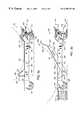
- FIG. 3 ais a side view of the roll cart of FIG. 1 .
- FIG. 3 bis a side view of the roll cart of FIG. 1 .
- FIG. 4is a detailed, exploded view of an exemplary combination braking/locking mechanism of the present invention.
- FIG. 5is an enlarged, fragmentary section of the combination braking/locking mechanism of FIG. 4 .
- FIG. 6is an enlarged, fragmentary section of the combination braking/locking mechanism of FIG. 4 .
- An exemplary embodiment of the present inventionis an improved roll cart device that can be used for moving a large roll of paper from a pallet in a warehouse to a printer at another location. These large rolls of paper can be over fifty inches in diameter and weigh over one half of a ton.
- the improved roll cart of the present inventionprovides a safe and efficient method of moving a roll of paper easily while minimizing damage to the paper.
- the deviceincludes a pivoting carriage that stabilizes a large roll of paper and permits easy loading and unloading of the roll.
- the carriageis pivotally attached to a frame so that the carriage can tilt and allow a roll of paper to be rolled onto or off of the carriage without lifting the roll.
- the carriagealso includes two inclined surfaces, stops or other projections, one at each end of the carriage, to stabilize the paper roll.
- the pivot pointis strategically placed on the carriage so that the carriage normally rests on the frame in a gravitationally stable and substantially horizontal resting position. From this position, the carriage can tilt or pivot to a gravitationally unstable position by applying force or weight to the leading edge of the carriage. In this tilted position, the inclined surface, stop or other projection pivots to a level below or flush with the top surface of the roll cart, so that a roll of paper can be loaded onto the carriage with lifting the roll of paper over the inclined surface, stop or projection.
- This tilting featureminimizes damage to the outside of the roll of paper and minimizes the amount of effort required to load and unload the roll of paper on to and off of the roll cart.
- the devicecan be securely maintained stationary with respect to a surface by engaging a brake.
- a brakeWhen the brake is engaged, rolling of the cart is impeded and the carriage pivots freely to allow loading or unloading of a roll by rolling the roll on to or off of the carriage.
- a locking mechanismengages the carriage to prevent the carriage from tilting.
- the brakeWhen the brake is disengaged, the cart is free to roll but the carriage is restricted from tilting or otherwise pivoting by the locking portion of the mechanism.
- This combination braking/locking featurenot only prevents the carriage from pivoting when the device is rolling, it also prevents inadvertent unloading of a roll and facilitates the safe transportation of large heavy rolls of paper.
- the roll cartcan also be used for moving other objects, particularly large objects of similar shape such as spools and rolls of other materials.
- the present inventionalso provides a method for moving a roll of paper from one raised surface to another raised surface that involves rolling the cart to a first raised surface upon which a roll of paper is located, engaging the brake portion of the combination braking/locking mechanism, rolling the roll of paper from the first raised surface on to one end of the cart, tipping the carriage by further rolling the roll of paper over the leading edge of the carriage and onto the carriage, and then pivoting the carriage back to a stable position.
- the braking portion of the combination braking/locking mechanismcan then be disengaged, engaging the locking portion of the combination braking/locking mechanism and preventing the carriage from pivoting.
- the cartis then loaded with a roll of paper and can be safely maneuvered and rolled to a desired location.
- the brakeis engaged, the lock is disengaged and the roll of paper can be rolled off the carriage and, desirably, on to another raised surface.
- FIGS. 1 through 6show an exemplary device, or roll cart 100 illustrating the present invention.
- the device 100is shown in perspective, loaded with a large roll of paper 900 .
- the large roll of paper 900can be used to print a large number of documents without having to change rolls frequently.
- several of the devices 100 of the illustrated embodimentcan be loaded with paper and lined up next to each other in a printing room to provide a ready inventory of paper for printing.
- the device 100is also shown with a partially illustrated means for pulling 800 the device, or roll cart 100 , inserted through a hole 310 in the device 100 .
- the means for pulling 800can be any device that can be used to push or pull the roll cart 100 and includes, but is not limited to, a removable hook, a T-grip and other similar devices (not illustrated).
- the hole 310is provided in the device 100 so that the means for pulling 800 can be inserted through the hole 310 and used by an individual (not illustrated) to pull the device 100 to a desired location.
- the means for pulling 800is typically used when the device 100 is empty so that an individual can pull an empty cart without having to bend down.
- a roll cart 100 that is loaded with the paper rollcan be pushed and maneuvered to a desired location by pushing on the roll that is loaded on the roll cart 100 .
- a second hole (not illustrated)can be provided at the end of the cart opposite the end on which the first hole 310 is provided, so that more than one roll cart 100 can be linked together and pulled in a train-like fashion.
- the roll of paper 900is shown resting on a carriage 200 that is supported on a rolling frame 300 .
- the frame 300is shown to be rectangular-shaped in the Figures, it can be any shape that allows the device to have the features that will be described.
- the device 100includes means for allowing the device to travel or roll across a surface 600 (FIG. 3 a ).
- the means for allowing the device 100 to travel or roll across a surfaceincludes two pairs of wheels 320 and 330 .
- the means for allowing the device 100 to roll or otherwise travel across the surfaceincludes any means used to facilitate the movement of an object over a surface and includes, but is not limited to, wheels, casters, tracks, rollers, bearings and the like.
- the frame 300rests on the first pair of wheels 320 that freely rotate to allow for steering of the device 100 and a second pair of wheels 330 that are stationary, much like on a conventional shopping cart.
- the wheels 320pivot about a vertical axis and are used for steering the device 100 . It is also desirable to provide the means for pulling 800 the device 100 and the hole 310 at the end of the device having the steerable wheels 320 .
- the frame 300is a one piece heavy gauge steel chassis that includes a central, rectangular opening 210 in which a carriage 200 is fitted.
- the carriage 200includes a first inclined surface 220 at one end of the carriage and a second inclined surface 230 at the other end of the carriage 200 .
- the inclined surface 220includes an opposing inclined surface 240 that faces away from the center of the carriage 200 and toward the end of the carriage.
- the inclined surface 240acts a leading edge and includes a top 250 .
- the carriage 200is designed to support and stabilize the large roll of paper 900 and is pivotally attached to the frame 300 so that the carriage can pivot about a horizontal axis, A—A at a point 340 .
- the carriage 200is attached to the frame 300 by a means for pivotally attaching the carriage 200 to the frame 300 .
- the means for pivotally attaching the carriage 200 to the frame 300can be an axle, a pair of bolts, a pair of pins or other like device or devices 350 that are used to pivotally attach one item to another item.
- the carriage 200is pivotally attached to the frame 300 at the point 340 proximate the first inclined surface 220 of the carriage 200 , so that the carriage 200 is pivotable horizontally about axis A—A.
- the carriage 200normally rests on the frame 300 in a gravitationally stable and substantially horizontal position as illustrated in FIG. 3 a .
- a top surface of the frame 360is about the same height as a standard pallet 700 so that a roll of paper 900 can be rolled directly off of the pallet 700 and onto the device 100 without raising or lowering the roll of paper 900 .
- a standard palletis typically about four and one-half inches in height. Therefore, it is desirable that the height from the bottom of the wheels 330 to the top surface 360 of the frame 300 is also about four and one-half inches.
- the roll of paper 900can be rolled off the pallet 700 , over the frame 300 , over the top surface 360 and onto the carriage 200 as illustrated in FIG. 3 b with minimal effort from the user. It is also desirable to design the height of the frame so that the frame can roll over an OSHA approved ramp (not illustrated).
- a key feature of the exemplary device 100is that the carriage 200 pivots to accept the roll 900 and includes two inclined surfaces, stops or other projections 220 and 230 , one at each end of the carriage, to stabilize the large diameter roll of paper 900 .
- the inclined surfaces 220 and 230 and a generally flat surface 260 of the carriage 200 there betweenare arranged so that the roll of paper 900 contacts all three surfaces 220 , 230 and 260 and is stabilized by or cradled by the three surfaces as illustrated in FIG. 3 a.
- the carriage 200includes a downward extending portion 270 that contacts the floor 600 , also illustrated in FIG. 3 b , and prevents the carriage 200 from tilting so far that the roll of paper 900 would fall down into the carriage 200 .
- the length of the downwardly extending portion 270 or the thickness of the carriage 200is desirably selected so that carriage 200 pivots enough for the top 250 of the inclined surface 220 to be approximately flush with or just below the top surface 360 but does not pivot so far that the top 250 of the inclined surface 220 is substantially lower than the top surface 360 of frame 300 .
- the roll of paper 900can be easily and smoothly rolled on to or off of the carriage 200 without a significant change in height, without lifting or lowering the roll of paper 900 and without damaging the outside of the roll of paper.
- FIG. 4is a detailed exploded view illustrating the individual components of the exemplary combination braking/locking mechanism 400 of the present invention.
- the combination braking/locking mechanism 400includes both means for restricting movement of the device 100 across a surface and means for restricting the tilting or otherwise pivoting of the carriage 200 relative to the frame 300 that function in an alternative manner.
- the combination braking/locking mechanism 400also includes separate means engaging the brake and for disengaging the brake.
- FIG. 5is an enlarged fragmentary section of the combination braking/locking mechanism 400 illustrating the locking portion of the mechanism in the engaged position and the brake portion of the mechanism in the up, disengaged, position.
- the device 100can roll freely across the surface 600 but the carriage 200 is restricted from pivoting or tilting by a locking mechanism and is in a gravitationally stable, substantially horizontal position.
- FIG. 6is a similar enlarged fragmentary section of the combination braking/locking mechanism 400 illustrating the locking portion of the mechanism in the disengaged position and the brake portion of the mechanism in the down, engaged, position. In the position illustrated in FIG. 6, the carriage 200 is free to pivot or tilt but the device 100 is restricted from rolling across the surface 600 by the brake portion of the mechanism.
- the combination braking/locking mechanism 400 of the illustrated, exemplary embodimentis a modified 4-inch floor brake assembly for a hand truck, model no. 66027756098, that was purchased from MSC.
- the brake assemblyincludes two interfitting, telescoping cylinders 410 and 420 connected to each other with bolts or pins 430 and 440 and springs 450 and 460 so that one cylinder can move within the other cylinder.
- To the lowermost cylinder 410is attached a brake pad 470 for contacting the floor surface 600 and restricting movement of the device 100 .
- braking/locking mechanism 400is illustrated as working in an alternating fashion where in only one engages at any one time, it may be desirable to provide a roll cart 100 in which a brake and a lock may be engaged simultaneously to provide a stationary cart 100 that is loaded with the roll 900 that is in a stable locked position.
- the brake assemblywas modified by adding a locking bar 480 to engage a portion 280 of the carriage 200 and prevent the carriage 200 from pivoting.
- the portion 280 of the carriageis an L-shaped extension extending from the underside of the carriage 200 that the locking bar 480 can extend into to prevent the carriage 200 from pivoting or otherwise tilting.
- the portion 280 of the carriagecan be of other configurations including, but not limited to, a U-shaped extension, a slot or a hole into which the locking portion of the combination braking/locking mechanism 400 can extend or otherwise engage (not illustrated).
- the locking bar 480is connected to a pedal 490 by a bolt 500 .
- the pedal 490is attached to the brake pad 470 and can be depressed to lower the brake pad 410 to the surface 600 and to also simultaneously pull the locking bar 480 away from or otherwise disengage the locking bar 480 from the carriage so that the carriage can tilt.
- the brake assembly 400also includes a lever 510 for raising the brake pad 470 from the down, brake engaged position while simultaneously engaging the locking bar 480 with the portion 280 of the carriage 200 .
- the frame 300further includes a guide 370 that supports and accurately guides the locking bar 480 into the portion 280 of the carriage.
- FIGS. 3 a and 3 billustrate the cooperation of the tilting of the carriage 200 for loading or unloading of the paper roll 900 and the operation of the combination/locking brake mechanism 400 .
- the carriage 200can tilt to facilitate the loading and unloading of the roll 900 on to and off of the carriage 200 , and, ultimately, the device 100 .
- FIG. 3 ais side view of the device of FIG.
- FIG. 3 bis a similar side view of the device of FIG. 1 but with the brake disengaged and with the carriage 200 in a tilted position.
- the height of the frame 300can be configured to receive the roll 900 from the conventional pallet 700 , as shown in FIG. 3 b . Because the rolls of paper 900 are typically shipped on pallets, the device 100 enables an individual to handle and transport the roll of paper 900 without lifting or otherwise raising or lowering the roll of paper 900 .
- the device 100 when loaded with the roll of paper 900has a low center of gravity.
- the loaded devices 100can be lined up to provide a ready inventory of paper and several empty devices can be vertically stacked upon one another when not in use to save storage space.
- the devices 100are configured so that one device can be stacked on top of another similar device by laying the wheels on one end of the second device on the top of the opposed end of the first device. In this manner, more than one similar devices can be stacked vertically in same the floor space required for one such device.
- the present inventionalso provides a method for moving a roll of paper from one raised surface, such as a pallet upon which such rolls are delivered, to another raised surface, such as a printer or an unwinding device on a printer.
- the methodinvolves rolling the device 100 to a first raised surface upon which a roll of paper is located, e.g.
- a palletengaging the brake portion of the combination braking/locking mechanism 400 , rolling a roll of paper from the pallet onto one end of the device, tipping the carriage 200 from a stable, substantially horizontal position to a tilted position by further rolling the roll of paper over the leading edge of the carriage, further rolling the roll of paper onto the carriage and pivoting the carriage back to the stable position, then disengaging the braking portion of the combination braking/locking mechanism and engaging the locking portion of the combination braking/locking mechanism that prevents the carriage from pivoting.
- the deviceis then safely loaded with a roll or paper and can easily be handled and maneuvered by an individual.
- the methodmay also include the use of a means for pulling the device, including but not limited to, a T-grip, a hook, a leash or any other similar device that can be inserted into the hole 310 and used to pull or to push the device 100 .
- a means for pulling the deviceincluding but not limited to, a T-grip, a hook, a leash or any other similar device that can be inserted into the hole 310 and used to pull or to push the device 100 .
- a means for pulling the deviceincluding but not limited to, a T-grip, a hook, a leash or any other similar device that can be inserted into the hole 310 and used to pull or to push the device 100 .
- Several devices loaded in such a mannercan be lined up in small area near the area the paper will be needed to provide a ready inventory of paper. Such inventorying can be used to minimize down time between changing rolls of paper on a printer.
- the deviceis 100 unloaded by rolling the device to a second raised surface upon which the roll of paper is to be unloaded, engaging the brake portion of the combination braking/locking mechanism 400 , tipping the carriage 200 from the stable position by rolling the roll of paper 900 over one of the projections, stops or raised surfaces on the surface of the carriage, and rolling the roll of paper off of the carriage and onto the second raised surface upon which the roll of paper is to be unloaded.
- the braking portion of the combination braking/locking mechanismcan now be safely disengaged and the device rolled away from the raised surface upon which the roll of paper was unloaded.
- the empty devicecan be stacked vertically upon one or more similarly shaped devices with the wheels of the top device laying over the opposing wheels and on the surface of the lower device.
Landscapes
- Engineering & Computer Science (AREA)
- Chemical & Material Sciences (AREA)
- Combustion & Propulsion (AREA)
- Transportation (AREA)
- Mechanical Engineering (AREA)
- Handcart (AREA)
Abstract
Description
Claims (20)
Priority Applications (2)
| Application Number | Priority Date | Filing Date | Title |
|---|---|---|---|
| US09/476,077US6390759B1 (en) | 1999-12-30 | 1999-12-30 | Integrated brake/tilt-release mechanism for a dolly with a pivoting carriage |
| US10/122,636US6860496B2 (en) | 1999-12-30 | 2002-04-15 | Dolly system for vehicle movement |
Applications Claiming Priority (1)
| Application Number | Priority Date | Filing Date | Title |
|---|---|---|---|
| US09/476,077US6390759B1 (en) | 1999-12-30 | 1999-12-30 | Integrated brake/tilt-release mechanism for a dolly with a pivoting carriage |
Related Child Applications (1)
| Application Number | Title | Priority Date | Filing Date |
|---|---|---|---|
| US10/122,636Continuation-In-PartUS6860496B2 (en) | 1999-12-30 | 2002-04-15 | Dolly system for vehicle movement |
Publications (1)
| Publication Number | Publication Date |
|---|---|
| US6390759B1true US6390759B1 (en) | 2002-05-21 |
Family
ID=23890414
Family Applications (1)
| Application Number | Title | Priority Date | Filing Date |
|---|---|---|---|
| US09/476,077Expired - LifetimeUS6390759B1 (en) | 1999-12-30 | 1999-12-30 | Integrated brake/tilt-release mechanism for a dolly with a pivoting carriage |
Country Status (1)
| Country | Link |
|---|---|
| US (1) | US6390759B1 (en) |
Cited By (35)
| Publication number | Priority date | Publication date | Assignee | Title |
|---|---|---|---|---|
| US20030038439A1 (en)* | 1999-12-30 | 2003-02-27 | Novak William J. | Dolly system for vehicle movement |
| USD473692S1 (en) | 2002-04-15 | 2003-04-22 | Jerry S. Tafoya | Tire lift dolly |
| US6719308B2 (en)* | 2001-12-06 | 2004-04-13 | First Data Corporation | Table carrier and methods |
| US20040156700A1 (en)* | 2003-02-07 | 2004-08-12 | The United States Of America As Represented By The Secretary Of The Army | Foldable tire dolly |
| US20050063795A1 (en)* | 2003-09-24 | 2005-03-24 | Jagos Roderick B. | Solid motor transport trailer with rotatable chock supports |
| US20060231670A1 (en)* | 2005-03-25 | 2006-10-19 | Giddens Barney T | Telescopic carpet conveyor |
| US20070080030A1 (en)* | 2005-10-06 | 2007-04-12 | Sunrise Medical Hhg Inc. | Brake assembly for beds |
| US20080088103A1 (en)* | 2006-10-13 | 2008-04-17 | Craig Sloat | Locking barrel caddie |
| US20080230292A1 (en)* | 2004-03-19 | 2008-09-25 | Falck Schmidt Defence Systems A/S | Self-Propelled Vehicle |
| US20080292434A1 (en)* | 2007-05-25 | 2008-11-27 | Michael John Wolterman | Assist device for a tire and wheel assembly |
| US20090169350A1 (en)* | 2007-12-27 | 2009-07-02 | Energy Saving Products & Sales Corp. | Paper roll transport cart |
| US20100276897A1 (en)* | 2009-04-29 | 2010-11-04 | Plummer Richard T | Airplane trailer |
| CN101891053A (en)* | 2010-07-30 | 2010-11-24 | 江南嘉捷电梯股份有限公司 | Transporter for escalator or moving sidewalk |
| US20120286491A1 (en)* | 2011-05-13 | 2012-11-15 | Angelo Iossa | Apparatus With Wire Cart For Moving, Storing and Dispensing Spooled Material |
| US20130327735A1 (en)* | 2012-06-08 | 2013-12-12 | K. Hartwall Oy Ab | Adaptor pallet |
| CN103802870A (en)* | 2014-02-28 | 2014-05-21 | 中国电力工程顾问集团西南电力设计院 | Simple pebble coal trolley |
| US8888110B2 (en) | 2011-11-15 | 2014-11-18 | Polymer Logistics (Israel) Ltd. | Pallet dolly |
| US20140360105A1 (en)* | 2012-11-12 | 2014-12-11 | Eco-Built Homes LLC | Telescoping frame system for portable home or other structure |
| US9045253B2 (en) | 2011-11-15 | 2015-06-02 | Polymer Logistics (Israel) Ltd. | Pallet-dolly |
| US20150203080A1 (en)* | 2014-01-23 | 2015-07-23 | Shivani Scientific Industries Private Limited | Method and apparatus for controlling mobility of a trolley |
| US9376132B1 (en)* | 2015-06-26 | 2016-06-28 | Mvp (H.K.) Industries Limited | Car dolly and methods of making and using same |
| US9610963B2 (en) | 2015-05-06 | 2017-04-04 | Chariot Concepts LLC | Vehicle tire cart |
| EP3461758A1 (en)* | 2017-09-29 | 2019-04-03 | WRH Walter Reist Holding AG | Device for transport of piece goods and containers |
| US10273111B2 (en) | 2016-12-20 | 2019-04-30 | Sonoco Development, Inc. | Devices for lifting, maneuvering, winding and unwinding reels |
| US10279827B1 (en)* | 2018-05-23 | 2019-05-07 | Paul Mason | Angle bar self-loading dolly |
| CN111361621A (en)* | 2020-03-19 | 2020-07-03 | 程达江 | Connecting rod alternate limiting-based steerable trolley for building |
| US10974749B2 (en) | 2018-04-23 | 2021-04-13 | Overhead Door Corporation | Trolley and method for moving long pallets |
| US11008193B2 (en) | 2017-09-27 | 2021-05-18 | First Data Corporation | Drive shaft for reusable paper core |
| US11014593B2 (en) | 2018-04-08 | 2021-05-25 | J-Tec Industries, Inc. | Tugger and rider cart assembly |
| US11046345B2 (en)* | 2017-02-07 | 2021-06-29 | Canon Kabushiki Kaisha | Tipping prevention unit, feeding apparatus, and image forming apparatus |
| CN113665654A (en)* | 2021-09-13 | 2021-11-19 | 广东电网有限责任公司 | Loading trolley |
| US20230050064A1 (en)* | 2021-08-03 | 2023-02-16 | Mts Maschinenbau Gmbh | Quick-change component store for workpieces |
| US20230047812A1 (en)* | 2021-08-13 | 2023-02-16 | Aqua Conscience Holdings LLC | Brake/ballast assembly for a movable structure |
| CN117657856A (en)* | 2023-12-30 | 2024-03-08 | 中重科技(天津)股份有限公司 | A rolling car |
| US20240227897A1 (en)* | 2023-01-11 | 2024-07-11 | Marlin Bedford | Vehicle Cart Assembly |
Citations (31)
| Publication number | Priority date | Publication date | Assignee | Title |
|---|---|---|---|---|
| US708346A (en)* | 1902-05-14 | 1902-09-02 | George H Grondin | Truck. |
| US1536611A (en) | 1922-11-08 | 1925-05-05 | Central Machine Works | Truck skid |
| US1789391A (en)* | 1927-05-27 | 1931-01-20 | Colson Company | Linoleum truck |
| US2189010A (en) | 1938-10-19 | 1940-02-06 | James W Lewis | Transporting apparatus |
| US2254564A (en)* | 1938-03-31 | 1941-09-02 | Caslake Charles Robert | Wheel truck |
| US2569050A (en)* | 1950-01-17 | 1951-09-25 | William C Gref | Article lifting and transporting dolly |
| US3111915A (en)* | 1962-02-05 | 1963-11-26 | Ekco Products Company | Merchandise handling rack |
| US3224612A (en)* | 1964-09-24 | 1965-12-21 | Hawkinson Paul E Co | Dolly for retreading molds and other wheel-like articles |
| US3285447A (en) | 1964-04-17 | 1966-11-15 | Melville E Junion | Shop truck |
| US3495850A (en) | 1968-08-19 | 1970-02-17 | Illinois Tool Works | Service cart |
| US3879053A (en)* | 1973-06-27 | 1975-04-22 | Coca Cola Co | Mobile display cart |
| US3897959A (en)* | 1974-05-23 | 1975-08-05 | Raymond L Haffner | Snowmobile dolly |
| US4067265A (en)* | 1976-08-27 | 1978-01-10 | Watson James C | Display rack |
| US4125269A (en)* | 1977-03-21 | 1978-11-14 | Kiel Louise A | Recliner-rocker geriatric wheel chair |
| US4240773A (en) | 1978-09-05 | 1980-12-23 | Terry Melvin D | Roll handling apparatus |
| US4318571A (en)* | 1980-02-07 | 1982-03-09 | Caterpillar Tractor Co. | Automatic brake control for tilting operator cab |
| US4582178A (en)* | 1984-06-12 | 1986-04-15 | Gilles Huneault | Seat brake system |
| US4593883A (en)* | 1984-12-10 | 1986-06-10 | Nelson Richard P | Portable lifting, loading and transporting device |
| US4655466A (en) | 1983-03-31 | 1987-04-07 | Hanaoka Sharyo Co., Ltd. | Cart |
| GB2201129A (en)* | 1987-02-21 | 1988-08-24 | Indespension Ltd | Trailer for handling reels |
| US5035445A (en)* | 1990-01-26 | 1991-07-30 | Poulin Willie F | Brake mechanism for carts and dollies |
| US5046748A (en) | 1990-04-06 | 1991-09-10 | Oat Judge Patricia C | Walker with automatic braking mechanism |
| US5052877A (en) | 1989-07-04 | 1991-10-01 | Nokia-Maillefer Holding S.A. | Carriage for the transportation of a cylindrical object |
| US5253972A (en) | 1992-01-30 | 1993-10-19 | Moore Business Forms, Inc. | Roll dolly |
| DE4239729A1 (en)* | 1992-11-26 | 1994-06-01 | Nwu Schneide Und Verpackungste | Cradle for moving coil material to packing machine - has coils held with horizontal axis of inclined sliding support for height adjustment |
| US5413449A (en)* | 1993-03-12 | 1995-05-09 | Wallace Computer Services, Inc. | Apparatus and method for handling business forms |
| US5464076A (en)* | 1994-06-02 | 1995-11-07 | Benedetto, Jr.; Alfred P. | Wheel support for securing a wheel of a wheeled vehicle to a transport vehicle |
| US5544719A (en) | 1993-04-09 | 1996-08-13 | G.D Societa' Per Azioni | Lift truck for transferring reels to a user machine |
| US5618152A (en)* | 1995-04-13 | 1997-04-08 | Andrews; Jeffrey F. | Printing machine spindle lifting and transporting cart |
| US6010296A (en)* | 1997-12-02 | 2000-01-04 | Enders; Bruce G. | Seat stowage cart for a removable vehicle seat |
| US6098761A (en)* | 1998-02-27 | 2000-08-08 | Dethmers Manufacturing Company, Inc. | Locking assembly for wheeled cargo transportation cart |
- 1999
- 1999-12-30USUS09/476,077patent/US6390759B1/ennot_activeExpired - Lifetime
Patent Citations (31)
| Publication number | Priority date | Publication date | Assignee | Title |
|---|---|---|---|---|
| US708346A (en)* | 1902-05-14 | 1902-09-02 | George H Grondin | Truck. |
| US1536611A (en) | 1922-11-08 | 1925-05-05 | Central Machine Works | Truck skid |
| US1789391A (en)* | 1927-05-27 | 1931-01-20 | Colson Company | Linoleum truck |
| US2254564A (en)* | 1938-03-31 | 1941-09-02 | Caslake Charles Robert | Wheel truck |
| US2189010A (en) | 1938-10-19 | 1940-02-06 | James W Lewis | Transporting apparatus |
| US2569050A (en)* | 1950-01-17 | 1951-09-25 | William C Gref | Article lifting and transporting dolly |
| US3111915A (en)* | 1962-02-05 | 1963-11-26 | Ekco Products Company | Merchandise handling rack |
| US3285447A (en) | 1964-04-17 | 1966-11-15 | Melville E Junion | Shop truck |
| US3224612A (en)* | 1964-09-24 | 1965-12-21 | Hawkinson Paul E Co | Dolly for retreading molds and other wheel-like articles |
| US3495850A (en) | 1968-08-19 | 1970-02-17 | Illinois Tool Works | Service cart |
| US3879053A (en)* | 1973-06-27 | 1975-04-22 | Coca Cola Co | Mobile display cart |
| US3897959A (en)* | 1974-05-23 | 1975-08-05 | Raymond L Haffner | Snowmobile dolly |
| US4067265A (en)* | 1976-08-27 | 1978-01-10 | Watson James C | Display rack |
| US4125269A (en)* | 1977-03-21 | 1978-11-14 | Kiel Louise A | Recliner-rocker geriatric wheel chair |
| US4240773A (en) | 1978-09-05 | 1980-12-23 | Terry Melvin D | Roll handling apparatus |
| US4318571A (en)* | 1980-02-07 | 1982-03-09 | Caterpillar Tractor Co. | Automatic brake control for tilting operator cab |
| US4655466A (en) | 1983-03-31 | 1987-04-07 | Hanaoka Sharyo Co., Ltd. | Cart |
| US4582178A (en)* | 1984-06-12 | 1986-04-15 | Gilles Huneault | Seat brake system |
| US4593883A (en)* | 1984-12-10 | 1986-06-10 | Nelson Richard P | Portable lifting, loading and transporting device |
| GB2201129A (en)* | 1987-02-21 | 1988-08-24 | Indespension Ltd | Trailer for handling reels |
| US5052877A (en) | 1989-07-04 | 1991-10-01 | Nokia-Maillefer Holding S.A. | Carriage for the transportation of a cylindrical object |
| US5035445A (en)* | 1990-01-26 | 1991-07-30 | Poulin Willie F | Brake mechanism for carts and dollies |
| US5046748A (en) | 1990-04-06 | 1991-09-10 | Oat Judge Patricia C | Walker with automatic braking mechanism |
| US5253972A (en) | 1992-01-30 | 1993-10-19 | Moore Business Forms, Inc. | Roll dolly |
| DE4239729A1 (en)* | 1992-11-26 | 1994-06-01 | Nwu Schneide Und Verpackungste | Cradle for moving coil material to packing machine - has coils held with horizontal axis of inclined sliding support for height adjustment |
| US5413449A (en)* | 1993-03-12 | 1995-05-09 | Wallace Computer Services, Inc. | Apparatus and method for handling business forms |
| US5544719A (en) | 1993-04-09 | 1996-08-13 | G.D Societa' Per Azioni | Lift truck for transferring reels to a user machine |
| US5464076A (en)* | 1994-06-02 | 1995-11-07 | Benedetto, Jr.; Alfred P. | Wheel support for securing a wheel of a wheeled vehicle to a transport vehicle |
| US5618152A (en)* | 1995-04-13 | 1997-04-08 | Andrews; Jeffrey F. | Printing machine spindle lifting and transporting cart |
| US6010296A (en)* | 1997-12-02 | 2000-01-04 | Enders; Bruce G. | Seat stowage cart for a removable vehicle seat |
| US6098761A (en)* | 1998-02-27 | 2000-08-08 | Dethmers Manufacturing Company, Inc. | Locking assembly for wheeled cargo transportation cart |
Cited By (50)
| Publication number | Priority date | Publication date | Assignee | Title |
|---|---|---|---|---|
| US6860496B2 (en) | 1999-12-30 | 2005-03-01 | First Data Corporation | Dolly system for vehicle movement |
| US20030038439A1 (en)* | 1999-12-30 | 2003-02-27 | Novak William J. | Dolly system for vehicle movement |
| US6719308B2 (en)* | 2001-12-06 | 2004-04-13 | First Data Corporation | Table carrier and methods |
| USD473692S1 (en) | 2002-04-15 | 2003-04-22 | Jerry S. Tafoya | Tire lift dolly |
| US20040156700A1 (en)* | 2003-02-07 | 2004-08-12 | The United States Of America As Represented By The Secretary Of The Army | Foldable tire dolly |
| US6863488B2 (en)* | 2003-02-07 | 2005-03-08 | The United States Of America As Represented By The Secretary Of The Army | Foldable tire dolly |
| US7246987B2 (en)* | 2003-09-24 | 2007-07-24 | The Boeing Company | Solid motor transport trailer with rotatable chock supports |
| US20050063795A1 (en)* | 2003-09-24 | 2005-03-24 | Jagos Roderick B. | Solid motor transport trailer with rotatable chock supports |
| US20080230292A1 (en)* | 2004-03-19 | 2008-09-25 | Falck Schmidt Defence Systems A/S | Self-Propelled Vehicle |
| US7360740B2 (en)* | 2005-03-25 | 2008-04-22 | Reagan Scott A | Telescopic carpet conveyor |
| US20060231670A1 (en)* | 2005-03-25 | 2006-10-19 | Giddens Barney T | Telescopic carpet conveyor |
| US20070080030A1 (en)* | 2005-10-06 | 2007-04-12 | Sunrise Medical Hhg Inc. | Brake assembly for beds |
| US20080088103A1 (en)* | 2006-10-13 | 2008-04-17 | Craig Sloat | Locking barrel caddie |
| US7963534B2 (en)* | 2006-10-13 | 2011-06-21 | Craig Sloat | Locking barrel caddie |
| US7918637B2 (en) | 2007-05-25 | 2011-04-05 | Toyota Motor Engineering & Manufacturing North America, Inc. | Assist device for a tire and wheel assembly |
| US20080292434A1 (en)* | 2007-05-25 | 2008-11-27 | Michael John Wolterman | Assist device for a tire and wheel assembly |
| US20090169350A1 (en)* | 2007-12-27 | 2009-07-02 | Energy Saving Products & Sales Corp. | Paper roll transport cart |
| US8096745B2 (en) | 2007-12-27 | 2012-01-17 | Energy Saving Products & Sales Corp. | Paper roll transport cart |
| US20100276897A1 (en)* | 2009-04-29 | 2010-11-04 | Plummer Richard T | Airplane trailer |
| US7976029B2 (en) | 2009-04-29 | 2011-07-12 | Richard T. Plummer | Airplane trailer |
| CN101891053A (en)* | 2010-07-30 | 2010-11-24 | 江南嘉捷电梯股份有限公司 | Transporter for escalator or moving sidewalk |
| US20120286491A1 (en)* | 2011-05-13 | 2012-11-15 | Angelo Iossa | Apparatus With Wire Cart For Moving, Storing and Dispensing Spooled Material |
| US8403345B2 (en)* | 2011-05-13 | 2013-03-26 | Michael Angelo Designs, Llc | Apparatus with wire cart for moving, storing and dispensing spooled material |
| US8888110B2 (en) | 2011-11-15 | 2014-11-18 | Polymer Logistics (Israel) Ltd. | Pallet dolly |
| US9045253B2 (en) | 2011-11-15 | 2015-06-02 | Polymer Logistics (Israel) Ltd. | Pallet-dolly |
| US20130327735A1 (en)* | 2012-06-08 | 2013-12-12 | K. Hartwall Oy Ab | Adaptor pallet |
| US9162814B2 (en)* | 2012-06-08 | 2015-10-20 | K. Hartwall Oy Ab | Adaptor pallet |
| US20140360105A1 (en)* | 2012-11-12 | 2014-12-11 | Eco-Built Homes LLC | Telescoping frame system for portable home or other structure |
| US20150203080A1 (en)* | 2014-01-23 | 2015-07-23 | Shivani Scientific Industries Private Limited | Method and apparatus for controlling mobility of a trolley |
| CN103802870A (en)* | 2014-02-28 | 2014-05-21 | 中国电力工程顾问集团西南电力设计院 | Simple pebble coal trolley |
| US9610963B2 (en) | 2015-05-06 | 2017-04-04 | Chariot Concepts LLC | Vehicle tire cart |
| AU2016203816B2 (en)* | 2015-06-26 | 2017-03-02 | Mvp (H. K.) Industries Limited | Car dolly and methods of making and using same |
| US9376132B1 (en)* | 2015-06-26 | 2016-06-28 | Mvp (H.K.) Industries Limited | Car dolly and methods of making and using same |
| US10273111B2 (en) | 2016-12-20 | 2019-04-30 | Sonoco Development, Inc. | Devices for lifting, maneuvering, winding and unwinding reels |
| US11365084B2 (en) | 2016-12-20 | 2022-06-21 | Sonoco Development, Inc. | Devices for lifting, maneuvering, winding and unwinding reels |
| US10759627B2 (en) | 2016-12-20 | 2020-09-01 | Sonoco Development, Inc. | Devices for lifting, maneuvering, winding and unwinding reels |
| US11046345B2 (en)* | 2017-02-07 | 2021-06-29 | Canon Kabushiki Kaisha | Tipping prevention unit, feeding apparatus, and image forming apparatus |
| US11008193B2 (en) | 2017-09-27 | 2021-05-18 | First Data Corporation | Drive shaft for reusable paper core |
| EP3461758A1 (en)* | 2017-09-29 | 2019-04-03 | WRH Walter Reist Holding AG | Device for transport of piece goods and containers |
| US11014593B2 (en) | 2018-04-08 | 2021-05-25 | J-Tec Industries, Inc. | Tugger and rider cart assembly |
| US10974749B2 (en) | 2018-04-23 | 2021-04-13 | Overhead Door Corporation | Trolley and method for moving long pallets |
| US10279827B1 (en)* | 2018-05-23 | 2019-05-07 | Paul Mason | Angle bar self-loading dolly |
| CN111361621A (en)* | 2020-03-19 | 2020-07-03 | 程达江 | Connecting rod alternate limiting-based steerable trolley for building |
| US20230050064A1 (en)* | 2021-08-03 | 2023-02-16 | Mts Maschinenbau Gmbh | Quick-change component store for workpieces |
| US12319330B2 (en)* | 2021-08-03 | 2025-06-03 | Mts Maschinenbau Gmbh | Quick-change component store for auto body parts |
| US20230047812A1 (en)* | 2021-08-13 | 2023-02-16 | Aqua Conscience Holdings LLC | Brake/ballast assembly for a movable structure |
| CN113665654A (en)* | 2021-09-13 | 2021-11-19 | 广东电网有限责任公司 | Loading trolley |
| US20240227897A1 (en)* | 2023-01-11 | 2024-07-11 | Marlin Bedford | Vehicle Cart Assembly |
| US12151730B2 (en)* | 2023-01-11 | 2024-11-26 | Marlin Bedford | Vehicle cart assembly |
| CN117657856A (en)* | 2023-12-30 | 2024-03-08 | 中重科技(天津)股份有限公司 | A rolling car |
Similar Documents
| Publication | Publication Date | Title |
|---|---|---|
| US6390759B1 (en) | Integrated brake/tilt-release mechanism for a dolly with a pivoting carriage | |
| US6860496B2 (en) | Dolly system for vehicle movement | |
| JP3393552B2 (en) | Product storage pallets with wheels | |
| KR0163352B1 (en) | Carriage for the transportaion of a cylindrical object | |
| US7462009B2 (en) | Hand-truck apparatus having locking handle | |
| US7416196B2 (en) | Tugger cart with rotating platform | |
| CN101918281A (en) | Adapter pallet and method for moving goods | |
| EP2813439A2 (en) | Adaptor pallet and method of transporting a plurality of dollies by means of an adaptor pallet | |
| US8006984B2 (en) | Stackable dolly | |
| US4023818A (en) | Tote bin for high density articles and material handling system | |
| KR20200001191A (en) | Easy to load and unload cart for cargo transportation | |
| JPH10101080A (en) | Tilted portable pallet | |
| US5582499A (en) | Pallet changing apparatus | |
| JP3141025B2 (en) | Transport equipment for transporting heavy loads | |
| US5618152A (en) | Printing machine spindle lifting and transporting cart | |
| CA2075312A1 (en) | Apparatus and method for hauling material objects | |
| US20030180130A1 (en) | Cart and lift system | |
| US20200207396A1 (en) | Pallet truck fixture | |
| JP6162201B2 (en) | Fork cover | |
| US20070183882A1 (en) | Removable stinger assembly for forklift and dolly | |
| JP2005075642A (en) | Mounting plate for fork cart | |
| JP3226073U (en) | dolly | |
| JPH07329970A (en) | Pallet | |
| JPH0360739B2 (en) | ||
| US20250206362A1 (en) | A hand trolley for receiving and transporting a legged fractional display platform |
Legal Events
| Date | Code | Title | Description |
|---|---|---|---|
| AS | Assignment | Owner name:FIRST DATA CORPORATION, NEBRASKA Free format text:ASSIGNMENT OF ASSIGNORS INTEREST;ASSIGNORS:CASTO, C FRED;BAILEY, DOUG S.;NOVAK, WILLIAM J;REEL/FRAME:010805/0074;SIGNING DATES FROM 20000425 TO 20000502 | |
| STCF | Information on status: patent grant | Free format text:PATENTED CASE | |
| FPAY | Fee payment | Year of fee payment:4 | |
| AS | Assignment | Owner name:CREDIT SUISSE, CAYMAN ISLANDS BRANCH, AS COLLATERA Free format text:SECURITY AGREEMENT;ASSIGNORS:FIRST DATA CORPORATION;CARDSERVICE INTERNATIONAL, INC.;FUNDSXPRESS, INC.;AND OTHERS;REEL/FRAME:020045/0165 Effective date:20071019 | |
| FPAY | Fee payment | Year of fee payment:8 | |
| AS | Assignment | Owner name:WELLS FARGO BANK, NATIONAL ASSOCIATION, AS COLLATERAL AGENT, NEW YORK Free format text:SECURITY AGREEMENT;ASSIGNORS:DW HOLDINGS, INC.;FIRST DATA RESOURCES, INC. (K/N/A FIRST DATA RESOURCES, LLC);FUNDSXPRESS FINANCIAL NETWORKS, INC.;AND OTHERS;REEL/FRAME:025368/0183 Effective date:20100820 Owner name:WELLS FARGO BANK, NATIONAL ASSOCIATION, AS COLLATE Free format text:SECURITY AGREEMENT;ASSIGNORS:DW HOLDINGS, INC.;FIRST DATA RESOURCES, INC. (K/N/A FIRST DATA RESOURCES, LLC);FUNDSXPRESS FINANCIAL NETWORKS, INC.;AND OTHERS;REEL/FRAME:025368/0183 Effective date:20100820 | |
| AS | Assignment | Owner name:WELLS FARGO BANK, NATIONAL ASSOCIATION, AS COLLATERAL AGENT, NEW YORK Free format text:SECURITY AGREEMENT;ASSIGNORS:DW HOLDINGS, INC.;FIRST DATA RESOURCES, LLC;FUNDSXPRESS FINANCIAL NETWORKS, INC.;AND OTHERS;REEL/FRAME:025719/0590 Effective date:20101217 Owner name:WELLS FARGO BANK, NATIONAL ASSOCIATION, AS COLLATE Free format text:SECURITY AGREEMENT;ASSIGNORS:DW HOLDINGS, INC.;FIRST DATA RESOURCES, LLC;FUNDSXPRESS FINANCIAL NETWORKS, INC.;AND OTHERS;REEL/FRAME:025719/0590 Effective date:20101217 | |
| FPAY | Fee payment | Year of fee payment:12 | |
| AS | Assignment | Owner name:FIRST DATA RESOURCES, LLC, COLORADO Free format text:RELEASE BY SECURED PARTY;ASSIGNOR:CREDIT SUISSE AG, CAYMAN ISLANDS BRANCH;REEL/FRAME:049902/0919 Effective date:20190729 Owner name:LINKPOINT INTERNATIONAL, INC., CALIFORNIA Free format text:RELEASE BY SECURED PARTY;ASSIGNOR:CREDIT SUISSE AG, CAYMAN ISLANDS BRANCH;REEL/FRAME:049902/0919 Effective date:20190729 Owner name:CARDSERVICE INTERNATIONAL, INC., CALIFORNIA Free format text:RELEASE BY SECURED PARTY;ASSIGNOR:CREDIT SUISSE AG, CAYMAN ISLANDS BRANCH;REEL/FRAME:049902/0919 Effective date:20190729 Owner name:DW HOLDINGS INC., COLORADO Free format text:RELEASE BY SECURED PARTY;ASSIGNOR:CREDIT SUISSE AG, CAYMAN ISLANDS BRANCH;REEL/FRAME:049902/0919 Effective date:20190729 Owner name:SIZE TECHNOLOGIES, INC., COLORADO Free format text:RELEASE BY SECURED PARTY;ASSIGNOR:CREDIT SUISSE AG, CAYMAN ISLANDS BRANCH;REEL/FRAME:049902/0919 Effective date:20190729 Owner name:FUNDSXPRESS, INC., TEXAS Free format text:RELEASE BY SECURED PARTY;ASSIGNOR:CREDIT SUISSE AG, CAYMAN ISLANDS BRANCH;REEL/FRAME:049902/0919 Effective date:20190729 Owner name:TELECHECK INTERNATIONAL, INC., TEXAS Free format text:RELEASE BY SECURED PARTY;ASSIGNOR:CREDIT SUISSE AG, CAYMAN ISLANDS BRANCH;REEL/FRAME:049902/0919 Effective date:20190729 Owner name:INTELLIGENT RESULTS, INC., COLORADO Free format text:RELEASE BY SECURED PARTY;ASSIGNOR:CREDIT SUISSE AG, CAYMAN ISLANDS BRANCH;REEL/FRAME:049902/0919 Effective date:20190729 Owner name:TELECHECK SERVICES, INC., TEXAS Free format text:RELEASE BY SECURED PARTY;ASSIGNOR:CREDIT SUISSE AG, CAYMAN ISLANDS BRANCH;REEL/FRAME:049902/0919 Effective date:20190729 Owner name:FIRST DATA CORPORATION, COLORADO Free format text:RELEASE BY SECURED PARTY;ASSIGNOR:CREDIT SUISSE AG, CAYMAN ISLANDS BRANCH;REEL/FRAME:049902/0919 Effective date:20190729 Owner name:TASQ TECHNOLOGY, INC., CALIFORNIA Free format text:RELEASE BY SECURED PARTY;ASSIGNOR:CREDIT SUISSE AG, CAYMAN ISLANDS BRANCH;REEL/FRAME:049902/0919 Effective date:20190729 | |
| AS | Assignment | Owner name:TASQ TECHNOLOGY, INC., NEW YORK Free format text:TERMINATION AND RELEASE OF SECURITY INTEREST IN PATENT RIGHTS;ASSIGNOR:WELLS FARGO BANK, NATIONAL ASSOCIATION;REEL/FRAME:050090/0060 Effective date:20190729 Owner name:LINKPOINT INTERNATIONAL, INC., NEW YORK Free format text:TERMINATION AND RELEASE OF SECURITY INTEREST IN PATENT RIGHTS;ASSIGNOR:WELLS FARGO BANK, NATIONAL ASSOCIATION;REEL/FRAME:050090/0060 Effective date:20190729 Owner name:FUNDSXPRESS FINANCIAL NETWORKS, INC., NEW YORK Free format text:TERMINATION AND RELEASE OF SECURITY INTEREST IN PATENT RIGHTS;ASSIGNOR:WELLS FARGO BANK, NATIONAL ASSOCIATION;REEL/FRAME:050090/0060 Effective date:20190729 Owner name:MONEY NETWORK FINANCIAL, LLC, NEW YORK Free format text:TERMINATION AND RELEASE OF SECURITY INTEREST IN PATENT RIGHTS;ASSIGNOR:WELLS FARGO BANK, NATIONAL ASSOCIATION;REEL/FRAME:050090/0060 Effective date:20190729 Owner name:INTELLIGENT RESULTS, INC. (K/N/A FIRST DATA SOLUTI Free format text:TERMINATION AND RELEASE OF SECURITY INTEREST IN PATENT RIGHTS;ASSIGNOR:WELLS FARGO BANK, NATIONAL ASSOCIATION;REEL/FRAME:050090/0060 Effective date:20190729 Owner name:FIRST DATA RESOURCES, INC. (K/N/A FIRST DATA RESOU Free format text:TERMINATION AND RELEASE OF SECURITY INTEREST IN PATENT RIGHTS;ASSIGNOR:WELLS FARGO BANK, NATIONAL ASSOCIATION;REEL/FRAME:050090/0060 Effective date:20190729 Owner name:TELECHECK INTERNATIONAL, INC., NEW YORK Free format text:TERMINATION AND RELEASE OF SECURITY INTEREST IN PATENT RIGHTS;ASSIGNOR:WELLS FARGO BANK, NATIONAL ASSOCIATION;REEL/FRAME:050090/0060 Effective date:20190729 Owner name:FIRST DATA CORPORATION, NEW YORK Free format text:TERMINATION AND RELEASE OF SECURITY INTEREST IN PATENT RIGHTS;ASSIGNOR:WELLS FARGO BANK, NATIONAL ASSOCIATION;REEL/FRAME:050090/0060 Effective date:20190729 Owner name:DW HOLDINGS, INC., NEW YORK Free format text:TERMINATION AND RELEASE OF SECURITY INTEREST IN PATENT RIGHTS;ASSIGNOR:WELLS FARGO BANK, NATIONAL ASSOCIATION;REEL/FRAME:050090/0060 Effective date:20190729 Owner name:SIZE TECHNOLOGIES, INC., NEW YORK Free format text:TERMINATION AND RELEASE OF SECURITY INTEREST IN PATENT RIGHTS;ASSIGNOR:WELLS FARGO BANK, NATIONAL ASSOCIATION;REEL/FRAME:050090/0060 Effective date:20190729 Owner name:SIZE TECHNOLOGIES, INC., NEW YORK Free format text:TERMINATION AND RELEASE OF SECURITY INTEREST IN PATENT RIGHTS;ASSIGNOR:WELLS FARGO BANK, NATIONAL ASSOCIATION;REEL/FRAME:050091/0474 Effective date:20190729 Owner name:TELECHECK INTERNATIONAL, INC., NEW YORK Free format text:TERMINATION AND RELEASE OF SECURITY INTEREST IN PATENT RIGHTS;ASSIGNOR:WELLS FARGO BANK, NATIONAL ASSOCIATION;REEL/FRAME:050091/0474 Effective date:20190729 Owner name:TASQ TECHNOLOGY, INC., NEW YORK Free format text:TERMINATION AND RELEASE OF SECURITY INTEREST IN PATENT RIGHTS;ASSIGNOR:WELLS FARGO BANK, NATIONAL ASSOCIATION;REEL/FRAME:050091/0474 Effective date:20190729 Owner name:MONEY NETWORK FINANCIAL, LLC, NEW YORK Free format text:TERMINATION AND RELEASE OF SECURITY INTEREST IN PATENT RIGHTS;ASSIGNOR:WELLS FARGO BANK, NATIONAL ASSOCIATION;REEL/FRAME:050091/0474 Effective date:20190729 Owner name:LINKPOINT INTERNATIONAL, INC., NEW YORK Free format text:TERMINATION AND RELEASE OF SECURITY INTEREST IN PATENT RIGHTS;ASSIGNOR:WELLS FARGO BANK, NATIONAL ASSOCIATION;REEL/FRAME:050091/0474 Effective date:20190729 Owner name:FIRST DATA SOLUTIONS, INC., NEW YORK Free format text:TERMINATION AND RELEASE OF SECURITY INTEREST IN PATENT RIGHTS;ASSIGNOR:WELLS FARGO BANK, NATIONAL ASSOCIATION;REEL/FRAME:050091/0474 Effective date:20190729 Owner name:DW HOLDINGS, INC., NEW YORK Free format text:TERMINATION AND RELEASE OF SECURITY INTEREST IN PATENT RIGHTS;ASSIGNOR:WELLS FARGO BANK, NATIONAL ASSOCIATION;REEL/FRAME:050091/0474 Effective date:20190729 Owner name:FUNDSXPRESS FINANCIAL NETWORK, INC., NEW YORK Free format text:TERMINATION AND RELEASE OF SECURITY INTEREST IN PATENT RIGHTS;ASSIGNOR:WELLS FARGO BANK, NATIONAL ASSOCIATION;REEL/FRAME:050091/0474 Effective date:20190729 Owner name:FIRST DATA CORPORATION, NEW YORK Free format text:TERMINATION AND RELEASE OF SECURITY INTEREST IN PATENT RIGHTS;ASSIGNOR:WELLS FARGO BANK, NATIONAL ASSOCIATION;REEL/FRAME:050091/0474 Effective date:20190729 Owner name:FIRST DATA RESOURCES, LLC, NEW YORK Free format text:TERMINATION AND RELEASE OF SECURITY INTEREST IN PATENT RIGHTS;ASSIGNOR:WELLS FARGO BANK, NATIONAL ASSOCIATION;REEL/FRAME:050091/0474 Effective date:20190729 Owner name:FIRST DATA CORPORATION, NEW YORK Free format text:TERMINATION AND RELEASE OF SECURITY INTEREST IN PATENT RIGHTS;ASSIGNOR:WELLS FARGO BANK, NATIONAL ASSOCIATION;REEL/FRAME:050094/0455 Effective date:20190729 Owner name:FIRST DATA RESOURCES, INC. (K/N/A FIRST DATA RESOURCES, LLC), NEW YORK Free format text:TERMINATION AND RELEASE OF SECURITY INTEREST IN PATENT RIGHTS;ASSIGNOR:WELLS FARGO BANK, NATIONAL ASSOCIATION;REEL/FRAME:050090/0060 Effective date:20190729 Owner name:INTELLIGENT RESULTS, INC. (K/N/A FIRST DATA SOLUTIONS, INC.), NEW YORK Free format text:TERMINATION AND RELEASE OF SECURITY INTEREST IN PATENT RIGHTS;ASSIGNOR:WELLS FARGO BANK, NATIONAL ASSOCIATION;REEL/FRAME:050090/0060 Effective date:20190729 |