US6390502B1 - Supplemental restraint assembly for an automotive vehicle - Google Patents
Supplemental restraint assembly for an automotive vehicleDownload PDFInfo
- Publication number
- US6390502B1 US6390502B1US09/817,783US81778301AUS6390502B1US 6390502 B1US6390502 B1US 6390502B1US 81778301 AUS81778301 AUS 81778301AUS 6390502 B1US6390502 B1US 6390502B1
- Authority
- US
- United States
- Prior art keywords
- air bag
- tether
- guides
- inboard
- secured
- Prior art date
- Legal status (The legal status is an assumption and is not a legal conclusion. Google has not performed a legal analysis and makes no representation as to the accuracy of the status listed.)
- Expired - Lifetime
Links
- 230000000153supplemental effectEffects0.000titleclaimsabstractdescription18
- 239000004744fabricSubstances0.000claimsdescription10
- 230000001681protective effectEffects0.000claimsdescription10
- WYTGDNHDOZPMIW-RCBQFDQVSA-NalstonineNatural productsC1=CC2=C3C=CC=CC3=NC2=C2N1C[C@H]1[C@H](C)OC=C(C(=O)OC)[C@H]1C2WYTGDNHDOZPMIW-RCBQFDQVSA-N0.000claimsdescription4
- 239000002699waste materialSubstances0.000claimsdescription4
- 230000001939inductive effectEffects0.000abstract1
- 239000004677NylonSubstances0.000description6
- 229920001778nylonPolymers0.000description6
- 239000000463materialSubstances0.000description5
- JOYRKODLDBILNP-UHFFFAOYSA-NEthyl urethaneChemical compoundCCOC(N)=OJOYRKODLDBILNP-UHFFFAOYSA-N0.000description3
- 230000002401inhibitory effectEffects0.000description2
- 238000012986modificationMethods0.000description2
- 230000004048modificationEffects0.000description2
- 239000004809TeflonSubstances0.000description1
- 229920006362Teflon®Polymers0.000description1
- 239000011248coating agentSubstances0.000description1
- 238000000576coating methodMethods0.000description1
- 230000001010compromised effectEffects0.000description1
- 238000011161developmentMethods0.000description1
- 230000018109developmental processEffects0.000description1
- 238000010438heat treatmentMethods0.000description1
- 230000002093peripheral effectEffects0.000description1
- 229920001296polysiloxanePolymers0.000description1
- 230000000717retained effectEffects0.000description1
- 239000004447silicone coatingSubstances0.000description1
- 239000000126substanceSubstances0.000description1
- XLYOFNOQVPJJNP-UHFFFAOYSA-NwaterSubstancesOXLYOFNOQVPJJNP-UHFFFAOYSA-N0.000description1
- 238000009941weavingMethods0.000description1
- 239000002759woven fabricSubstances0.000description1
Images


Classifications
- B—PERFORMING OPERATIONS; TRANSPORTING
- B60—VEHICLES IN GENERAL
- B60R—VEHICLES, VEHICLE FITTINGS, OR VEHICLE PARTS, NOT OTHERWISE PROVIDED FOR
- B60R21/00—Arrangements or fittings on vehicles for protecting or preventing injuries to occupants or pedestrians in case of accidents or other traffic risks
- B60R21/02—Occupant safety arrangements or fittings, e.g. crash pads
- B60R21/16—Inflatable occupant restraints or confinements designed to inflate upon impact or impending impact, e.g. air bags
- B60R21/23—Inflatable members
- B60R21/231—Inflatable members characterised by their shape, construction or spatial configuration
- B60R21/2334—Expansion control features
- B60R21/2338—Tethers
- B—PERFORMING OPERATIONS; TRANSPORTING
- B60—VEHICLES IN GENERAL
- B60R—VEHICLES, VEHICLE FITTINGS, OR VEHICLE PARTS, NOT OTHERWISE PROVIDED FOR
- B60R21/00—Arrangements or fittings on vehicles for protecting or preventing injuries to occupants or pedestrians in case of accidents or other traffic risks
- B60R21/02—Occupant safety arrangements or fittings, e.g. crash pads
- B60R21/16—Inflatable occupant restraints or confinements designed to inflate upon impact or impending impact, e.g. air bags
- B60R21/23—Inflatable members
- B60R21/231—Inflatable members characterised by their shape, construction or spatial configuration
- B60R21/232—Curtain-type airbags deploying mainly in a vertical direction from their top edge
- B—PERFORMING OPERATIONS; TRANSPORTING
- B60—VEHICLES IN GENERAL
- B60R—VEHICLES, VEHICLE FITTINGS, OR VEHICLE PARTS, NOT OTHERWISE PROVIDED FOR
- B60R21/00—Arrangements or fittings on vehicles for protecting or preventing injuries to occupants or pedestrians in case of accidents or other traffic risks
- B60R21/02—Occupant safety arrangements or fittings, e.g. crash pads
- B60R21/16—Inflatable occupant restraints or confinements designed to inflate upon impact or impending impact, e.g. air bags
- B60R21/23—Inflatable members
- B60R21/231—Inflatable members characterised by their shape, construction or spatial configuration
- B60R21/2334—Expansion control features
- B60R21/2338—Tethers
- B60R2021/23386—External tether means
Definitions
- This inventionrelates to a supplemental restraint assembly for an automotive vehicle and more particularly to a self-tensioning side impact air bag assembly.
- Air bags mounted in an instrument panel or steering wheel to protect an occupant from a front impacthave become standard in the automotive industry. Numerous variations of these air bags, deployment systems and housing devices have evolved over the years. However, these frontal air bags do not provide protection to the occupant during a side impact. Recent developments have focussed on technology directed to side impact air bags and related systems.
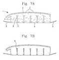
- FIGS. 7A and 7Bdepict a side impact air bag 1 of the related art.
- the air bag 1has a top edge 3 and a lower edge 4 .
- a front tether 5 and rear tether 6connects the inflatable element 2 to corresponding front and rear pillars of an automotive vehicle.
- the top edge 3has a plurality of mounting connections 7 for connection to the vehicle's roof rail.
- the air bag 1may have a plurality of straight substantially square zero length tethers 8 extending from the lower edge 4 to the top edge 3 .
- FIG. 6Bdepicts the air bag of FIG. 6A in an inflated state.
- the inflatable element 2shrinks when inflated and induces tension in the lower edge 4 and the tethers 5 , 6 .
- the present inventionis directed to a side impact air bag with a self-tensioning tether/lace interlaced within the side air bag.
- a side air bagis secured to the vehicle along the roof rail between the front and rear pillars.
- a tether or laceis secured to the air bag and traverses a plurality of predetermined guide points.
- the side impact air bagWhen the side impact air bag is inflated the distance between the guide points increases and any slack in the tether/lace is taken up. Thus the air bag is securely held in place when deployed.
- the side impact airbagserves to mitigate the threat of an occupant being ejected during a roll over event or subsequent impact.
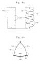
- FIG. 1is an elevation view of a side impact air bag of the present invention mounted to an automotive vehicle in a stored position.
- FIG. 2Ais an elevation view of a side impact air bag according to one embodiment of the present invention mounted to a vehicle in a deployed non-inflated state.
- FIG. 2Bis an elevation view of the side impact air bag of FIG. 2A in an inflated state.
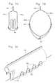
- FIG. 3Ais a cross sectional view of the side air bag of FIG. 2A taken along section lines 3 A— 3 A.
- FIG. 3Bis a cross sectional view of the side air bag of FIG. 2B taken along section lines 3 B— 3 B.
- FIG. 3Cis an elevational perspective view of the air bag of FIG. 2 B.
- FIG. 4Ais an exploded plan view of the bottom portion of the side air bag according to an alternative embodiment according to the present invention.
- FIG. 4Bis a cross sectional view of the air bag according to the alternate embodiment of FIG. 4 A.
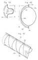
- FIG. 5Ais a cross sectional view of the air bag according to an alternate embodiment in a deflated state.
- FIG. 5Bis a cross sectional view of the air bag of FIG. 5A by in an inflated state.
- FIG. 5Cis an elevational perspective view of the air bag of FIG. 5 B.
- FIG. 6Ais a cross sectional view of the air bag according to an alternate embodiment in a deflated state.
- FIG. 6Bis a cross sectional view of the air bag of FIG. 6A in an inflated state.
- FIG. 6Cis an elevational perspective view of the air bag of FIG. 6 B.
- FIG. 7Ais an elevation view of a side impact air bag of the related art in a non-inflated stated.
- FIG. 7Bis an elevation view of the side impact air bag of FIG. 6A in an inflated state
- FIG. 1is directed to an air bag of the present invention mounted to an automotive vehicle in a stored non-deployed state.
- An automobile 20has a front pillar 25 , a rear pillar 26 and a center pillar 23 .
- An air bag 1is stored and mounted to the vehicle roof rail 24 .
- a front portion 31 of a tether/laceis connected to a front portion of the air bag 1 and to the front pillar 25 .
- a rear portion 32 of the tether/laceis connected to a rear portion of the air bag 1 and to the rear pillar 26 .
- the rear portion of the air bag 1is connected to a gas generator 29 , or a duct leading from a gas generator to facilitate ingress of gas to the airbag 1 .
- the air bag 1is stored in a compartment mounted to the roof rail 24 as shown in FIG. 1 .
- Front and rear portions 31 , 32 of the tether/laceare also stored in a compartment in a corresponding pillar 25 , 26 .
- the air bag 1is inflated by gas from generator 29 .
- the air bag 1inflates, it drops downward and is positioned and retained by the tethers 31 , 32 as well as the point-wise mounting connections 7 .
- gas fills the inflatable element 1the air bag 1 expands and a distance between a plurality of discretely positioned tether/lace guides increases.
- the length of the tether/lace required to span the length of the air bag 1increases.
- any slack in the tether/lace existing when the air bag 1 descends from its stored positionis taken up by the expanding air bag 1 and the increased distance between the tether/lace guides.
- the tethers 131 , 132are taut in the inflated state as shown in FIG. 2 B.
- the air bag 101is thereby positioned between the occupant and the door or window opening to protect the occupant from side impacts and subsequent events, such as rollover or secondary impact.
- FIGS. 2A-2Bis directed to a side impact air bag 101 of the present invention.
- the front and rear portions 131 , 132 of the tether/lacesecures the air bag 1 between the A-pillar 125 and C-pillar 126 spanning the B-pillar 123 .
- the air bag 101may be made to extend more rearwardly and secured to a D-pillar of a longer vehicle.
- the airbag 101may be employed only in the forward compartment of the vehicle and connected to the A-pillar and B-pillars. It is preferred, however, to employ a single air bag 101 for both the front and rear passenger compartments, and therefore connect the inflatable element to the A-pillar (or front pillar 125 ) and the C-pillar (rear pillar 126 ).
- the air bag 101may be made of any suitable air bag material for holding gas, but is preferably made of a plurality of sheets of woven nylon fabric lined with urethane or other substantially impervious material such as silicone.
- the urethane coated nylon sheetsare secured to one another along an outer periphery thereof to define the overall air bag shape.
- the sheetsare connected along the pattern shown in dotted lines in FIGS. 2A-2B.
- the nylon sheetsare secured to one another by heating selected portions of the fabric dialectrically.
- the urethane or silicone coating of each of the two nylon sheetsis laid against each other and together line the interior of the air bag 101 .
- the air bag 101is then dialectrically treated to heat the outer causing the coating to adhere to one another.
- the coated nylon sheetsmay also be stitched along the outer periphery to increase structural integrity sufficient to tolerate loads during inflation.
- stitchingit is preferred to treat the stitched area with a gas impervious substance to minimize gas leakage. Otherwise, the stress induced during inflation causes small holes in the stitching to widen and permit gas to escape thereby increasing deflation time.
- a bladdermay also be used to line the inner surface of the air bag to maintain the air bag in an inflated state for a longer period of time.
- the front and rear portions 131 , 132 of the tether/laceform a part of a single woven cord or fabric laced about a plurality of discrete points on the air bag 101 .
- the air bag 101inflates, the distance between the discrete points increases and slack is taken up in the tether/lace.
- the front and rear portions 131 , 132 of the tether/laceare slack.
- the air bag 101is inflated as illustrated in FIG.
- any slack in the tether/lace between the front and rear portions 131 , 132is taken up and the tether/lace is taut thereby positioning the air bag 101 within the vehicle and holding the air bag 101 in place.
- the preferred embodiments for weaving the tether/lace about the air bag 101will now be discussed.
- FIG. 3Arepresents a cross sectional view of an air bag 201 in a deflated state.
- the air bag 201is comprised of three panels 201 a , 201 b , and 201 c sewn together.
- An inboard panel 201 awhich faces the inner compartment of the vehicle, is sewn to an outboard panel 201 b along a top edge 203 of the air bag 201 .
- a bottom panel 201 cis sewn to each of the inboard 201 a and outboard 201 b panel forming a connection there between and defining the boundaries of the air bag 201 .
- a plurality of grommets 235are formed in a portion of the waste area outside of the stitching connecting the bottom panel 201 c with each of the inboard 201 a and outboard panel 201 b .
- the tether/lace 230is woven through the grommets 235 traversing the air bag 201 a number of times as the tether/lace 230 extends the length of the air bag 201 emerging to the front and rear portions thereof 131 , 132 for connection to the front and rear pillars 125 , 126 respectively.
- a pair of grommets 235are disposed immediately adjacent one another to allow the tether/lace 230 to immediately pass back through the bottom portion of the air bag 201 . Such an arrangement limits the exposure of the tether/lace 230 and helps prevent the tether/lace 230 from rubbing against the air bag or otherwise causing kinking.
- the distance between the inboard panel 201 a and outboard panel 201 b adjacent the bottom panelis relatively small in the deflated state.
- Such an arrangementallows the air bag 201 and tether/lace 230 to be stored up through the front and rear pillars 125 , 126 and roof rail 124 in a non-deployed stored state.
- FIG. 2Bwhen the air bag is deployed, as shown in FIG. 2B, a smaller distance spans directly between the front and rear pillars 125 , 126 . Therefore, slack must be taken up during inflation to provide tension in the tether/lace 230 to maintain the air bag 201 in proper position.
- the air bag 201is in an inflated state.
- the distance between the grommets 235 on the inboard side of the air bag and the outboard side of the air bagis significantly greater.
- the distance the tether/lace 230 must spanis increased and slack is therefore taken up.
- the distance that the tether/lace 230 traverses as the air bag inflates, above that of a straight line between the connection points of the front and rear pillars 125 , 126is greater than the increased distance that the tether/lace 230 must span when stored up through the front and rear pillars 125 , 126 and across the roof rail 124 .
- a protective cover 228may be disposed over the bottom panel 201 c sandwiching the tether/lace 230 there between. Such an arrangement isolates the tether/lace 230 during deployment and prevents foreign objects from inhibiting the relative movement of the tether/lace 230 relative to the air bag 201 during inflation thus inhibiting kinking.
- FIGS. 4A and 4Brepresent an alternate embodiment for lacing the tether/lace 330 along the air bag 301 .
- the tether/lace 330traverses a plurality of discrete points or lace guides 335 in a serpentine fashion.
- the discrete points or lace guides 335are formed by firmly stitching the bottom panel 301 c and a protective cover 328 together at each of the lace guides/points 335 .
- the air bag 301is uninflated, the inboard and outboard sides of the bottom panel 301 c and protective cover 328 are closer together similar to the embodiment of FIG. 3 A.
- the length of the tether/lace 330 needed to span the air bag 301 in a deflated/stored stateis shorter than when inflated. This allows the tether/lace 330 to be stored up through the pillars 125 , 126 and along the roof rail.
- the air bag 301 inflatesthe inboard and outboard sides of the bottom panel 301 c and protective cover 328 move apart and the tether lace 330 must traverse the width of the bottom panel 301 c a number of times proportionate to the number of guides 335 .
- Increasing the number of guides 335will increase the length of tether/lace 330 needed to span the air bag 301 and the amount of slack take-up during inflation.
- Such an arrangementeliminates the need for grommets and any exposure of the tether/lace 330 to the interior of the vehicle along the length of the air bag 301 .
- FIGS. 5A-5Crepresents another embodiment of the present invention.
- the air bag 401comprises two panels.
- An inboard panel 401 ais secured to an outboard panel 401 b along a top edge 403 and bottom edge 404 .
- a plurality of tether/lace guides 435are formed on both sides of the air bag 401 a , 401 b .
- the guides 435are preferably formed of fabric looped back onto itself and stitched to the side of the air bag 401 .
- the fabric guide 435is preferably made of the same material as the air bag 401 .
- the tether/lace 430is simply fed through each fabric guide 435 traversing the bottom edge 404 of the air bag 401 between each successive guide 435 as illustrated in FIG. 5 C.
- the distance between the guides 435is small whereas when the air bag 401 is inflated, the span increases requiring a greater length of the tether/lace 435 to span the overall length of the air bag 401 .
- Such an arrangementprovides an added benefit as the tether/lace 435 may be secured to the side of the air bag without the need for a zero length tether. If a grommet or slit were used as a guide 435 and the tether/lace 430 fed there through, the integrity of the air bag would be compromised and air would escape thus defeating the utility of the air bag. To avoid such a breach, a zero length tether must be formed about the guide point should a grommet or simple slit be employed.
- the present embodimenteliminates the need for a zero length tether. However, the present embodiment does not exclude the use of a zero length tether and may so be employed together with the present arrangement.
- FIGS. 6A-6Crepresent yet another embodiment of the present invention.
- a two-panel air bag 501is employed.
- Inboard panel 501 ais secured to an outboard panel 502 b along a top edge 503 and bottom edge 504 .
- the two panelsare simply stitched together, or as previously discussed, may be dielectrically adhered to one another in addition to the stitching.
- a plurality of tether/lace guides 535are formed along the top edge 503 and bottom edge 504 of the air bag 501 in a similar fashion to the embodiment of FIG. 3 C. That is, the guides 535 are formed outside of the stitching in a waste area unexposed to the internal pressure of the inflating gas.
- a plurality of fabric loop guidesmay be used in a similar fashion as shown in the previous embodiment.
- the tether/lace 530is fed through the guides 535 only along the inboard panel 501 b .
- Such an arrangementremoves the exposure of the tether/lace 530 to the inside of the vehicle. Therefore, a pair of immediately adjacent guides 535 is formed at each point along the top and bottom edges of the air bag.
- a protective cover 528may also be employed to isolate the tether/lace 530 within the air bag 501 .
- L 1represents a distance between the top and bottom edge of the air bag when inflated.
- L 2the distance between the top edge 503 and bottom edge 504 when uninflated.
- the air bag 501may be folded to position the top 503 and bottom 504 edges immediately adjacent one another thereby substantially reducing the length there between. Such an arrangement increases the amount of slack take up in the tether/lace 530 when the air bag inflates from its uniflated stored state in the roof rail.
- the material used for the tether/lacein each of the aforementioned embodiments, may be that as is known in the art.
- a water based Teflon coated thick nylon tape or other strong woven fabric or cordmay be employed.
- the tether/lacehave no substantial independent elastic properties. That is, the tether/lace should be able to endure the desired tension without significant elongation or substantially shrinkage when tension is relieved. It is also desirable to have a strong flexible material having an external surface of relatively low frictional characteristics to facilitate easy movement relative to the air bag and guide points. It is also noted that the tether/lace may be secured to the pillars in any suitable fashion known in the art.
Landscapes
- Engineering & Computer Science (AREA)
- Mechanical Engineering (AREA)
- Air Bags (AREA)
Abstract
Description
Claims (13)
Priority Applications (1)
| Application Number | Priority Date | Filing Date | Title |
|---|---|---|---|
| US09/817,783US6390502B1 (en) | 2001-03-26 | 2001-03-26 | Supplemental restraint assembly for an automotive vehicle |
Applications Claiming Priority (1)
| Application Number | Priority Date | Filing Date | Title |
|---|---|---|---|
| US09/817,783US6390502B1 (en) | 2001-03-26 | 2001-03-26 | Supplemental restraint assembly for an automotive vehicle |
Publications (1)
| Publication Number | Publication Date |
|---|---|
| US6390502B1true US6390502B1 (en) | 2002-05-21 |
Family
ID=25223874
Family Applications (1)
| Application Number | Title | Priority Date | Filing Date |
|---|---|---|---|
| US09/817,783Expired - LifetimeUS6390502B1 (en) | 2001-03-26 | 2001-03-26 | Supplemental restraint assembly for an automotive vehicle |
Country Status (1)
| Country | Link |
|---|---|
| US (1) | US6390502B1 (en) |
Cited By (31)
| Publication number | Priority date | Publication date | Assignee | Title |
|---|---|---|---|---|
| US6554314B1 (en)* | 1999-02-03 | 2003-04-29 | Takata Corporation | Protective cushion for vehicle occupant's head |
| US20030178820A1 (en)* | 2002-03-19 | 2003-09-25 | Green David J. | Inflatable curtain mudule for use in a vehicle |
| US20030205888A1 (en)* | 2002-05-03 | 2003-11-06 | Ramesh Keshavaraj | Modular air bag cushion system |
| US6648368B2 (en)* | 2002-03-27 | 2003-11-18 | General Motors Corporation | Dual roof rail air bag with integrated fill system |
| US20030227160A1 (en)* | 2002-06-06 | 2003-12-11 | Paul Dinsdale | Biaxial flow inflator with independently adjusted gas orfices |
| US6712389B2 (en)* | 2002-02-01 | 2004-03-30 | Trw Vehicle Safety Systems Inc. | Air bag with tether |
| US6742806B2 (en)* | 2001-01-11 | 2004-06-01 | Toyoda Gosei Co., Ltd. | Airbag and its wrapping method |
| US6746046B2 (en) | 2002-03-19 | 2004-06-08 | Autoliv Asp, Inc. | Dual flow inflator for a vehicular airbag system |
| US6820898B2 (en) | 2002-03-19 | 2004-11-23 | Autoliv Asp, Inc. | Biaxial dual stage inflator with extended gas delivery for a vehicular airbag system |
| US6832778B2 (en) | 2002-07-19 | 2004-12-21 | Delphi Technologies, Inc. | Air bag restraint including selectively operable venting elements |
| US20050104343A1 (en)* | 2003-11-19 | 2005-05-19 | Mark Levine | Side airnet cushioning/ restraint device |
| EP1676753A1 (en) | 2004-12-30 | 2006-07-05 | Delphi Technologies, Inc. | Apparatus and method for controlling an inflatable cushion |
| US7297186B1 (en)* | 2004-05-06 | 2007-11-20 | The United States Of America As Represented By The Secretary Of The Navy | Tethered, inflatable holder for flowable material |
| US20080258442A1 (en)* | 2007-04-23 | 2008-10-23 | Trw Vehicle Safety Systems Inc. | Method and apparatus for placing an inflatable curtain in a stored condition |
| US20090236828A1 (en)* | 2008-03-19 | 2009-09-24 | Daniel Nick Foubert | Inflatable personal restraint systems having web-mounted inflators and associated methods of use and manufacture |
| US7665761B1 (en) | 2008-03-27 | 2010-02-23 | Amsafe, Inc. | Inflatable personal restraint systems and associated methods of use and manufacture |
| US7991049B2 (en)* | 1998-11-09 | 2011-08-02 | Broadcom Corporation | Video and graphics system with video scaling |
| US20120049498A1 (en)* | 2010-08-27 | 2012-03-01 | Gm Global Technology Operations, Inc. | Airbag system |
| US8282126B2 (en) | 2010-10-13 | 2012-10-09 | Tk Holdings Inc. | Occupant restraint system |
| US8439398B2 (en) | 2011-07-29 | 2013-05-14 | Amsafe, Inc. | Inflator connectors for inflatable personal restraints and associated systems and methods |
| US8469397B2 (en) | 2011-04-13 | 2013-06-25 | Amsafe, Inc. | Stitch patterns for restraint-mounted airbags and associated systems and methods |
| US8523220B1 (en) | 2012-03-19 | 2013-09-03 | Amsafe, Inc. | Structure mounted airbag assemblies and associated systems and methods |
| US8740247B1 (en)* | 2012-12-27 | 2014-06-03 | Nissan North America, Inc. | Airbag assembly |
| US8848792B2 (en) | 1998-11-09 | 2014-09-30 | Broadcom Corporation | Video and graphics system with video scaling |
| US9352839B2 (en) | 2014-10-02 | 2016-05-31 | Amsafe, Inc. | Active positioning airbag assembly and associated systems and methods |
| US9511866B2 (en) | 2012-03-19 | 2016-12-06 | Amsafe, Inc. | Structure mounted airbag assemblies and associated systems and methods |
| US9925950B2 (en) | 2015-04-11 | 2018-03-27 | Amsafe, Inc. | Active airbag vent system |
| US9944245B2 (en) | 2015-03-28 | 2018-04-17 | Amsafe, Inc. | Extending pass-through airbag occupant restraint systems, and associated systems and methods |
| US20180281736A1 (en)* | 2017-03-31 | 2018-10-04 | Subaru Corporation | Curtain airbag |
| US10604259B2 (en) | 2016-01-20 | 2020-03-31 | Amsafe, Inc. | Occupant restraint systems having extending restraints, and associated systems and methods |
| US11130466B2 (en)* | 2019-03-08 | 2021-09-28 | Trw Vehicle Safety Systems Inc. | Airbag with deployment controlling tether |
Citations (12)
| Publication number | Priority date | Publication date | Assignee | Title |
|---|---|---|---|---|
| US3687485A (en)* | 1971-01-11 | 1972-08-29 | Gen Motors Corp | Occupant restraint system |
| US5865462A (en)* | 1996-09-19 | 1999-02-02 | Breed Automotive Technology, Inc. | Inflatable restraint for a vehicle occupant |
| US6095551A (en)* | 1999-08-02 | 2000-08-01 | Trw Inc. | Non-inflatable curtain with inflatable device |
| US6152481A (en)* | 1998-08-03 | 2000-11-28 | Delphi Technologies, Inc. | Side restraint assembly |
| US6155597A (en)* | 1999-05-11 | 2000-12-05 | Trw Vehicle Safety Systems Inc. | Vehicle occupant protection device with spring connector |
| US6168191B1 (en)* | 1999-06-11 | 2001-01-02 | Delphi Technologies, Inc. | Inflatable air bag for an automotive vehicle |
| US6203058B1 (en)* | 2000-02-24 | 2001-03-20 | Trw Inc. | Inflatable curtain with two inflatable members |
| US6237938B1 (en)* | 1999-09-01 | 2001-05-29 | Trw Vehicle Safety Systems Inc. | Inflatable curtain with anchor device |
| US6237939B1 (en)* | 2000-01-21 | 2001-05-29 | Trw Vehicle Safety Systems Inc. | Inflatable curtain |
| US6237941B1 (en)* | 1998-02-20 | 2001-05-29 | Breed Automotive Technology, Inc. | Inflatable side airbag curtain module |
| US6273458B1 (en)* | 2000-05-31 | 2001-08-14 | Trw Vehicle Safety Systems Inc. | Inflatable curtain |
| US6299199B1 (en)* | 1999-09-17 | 2001-10-09 | Trw Vehicle Safety Systems Inc. | Inflatable side curtain |
- 2001
- 2001-03-26USUS09/817,783patent/US6390502B1/ennot_activeExpired - Lifetime
Patent Citations (12)
| Publication number | Priority date | Publication date | Assignee | Title |
|---|---|---|---|---|
| US3687485A (en)* | 1971-01-11 | 1972-08-29 | Gen Motors Corp | Occupant restraint system |
| US5865462A (en)* | 1996-09-19 | 1999-02-02 | Breed Automotive Technology, Inc. | Inflatable restraint for a vehicle occupant |
| US6237941B1 (en)* | 1998-02-20 | 2001-05-29 | Breed Automotive Technology, Inc. | Inflatable side airbag curtain module |
| US6152481A (en)* | 1998-08-03 | 2000-11-28 | Delphi Technologies, Inc. | Side restraint assembly |
| US6155597A (en)* | 1999-05-11 | 2000-12-05 | Trw Vehicle Safety Systems Inc. | Vehicle occupant protection device with spring connector |
| US6168191B1 (en)* | 1999-06-11 | 2001-01-02 | Delphi Technologies, Inc. | Inflatable air bag for an automotive vehicle |
| US6095551A (en)* | 1999-08-02 | 2000-08-01 | Trw Inc. | Non-inflatable curtain with inflatable device |
| US6237938B1 (en)* | 1999-09-01 | 2001-05-29 | Trw Vehicle Safety Systems Inc. | Inflatable curtain with anchor device |
| US6299199B1 (en)* | 1999-09-17 | 2001-10-09 | Trw Vehicle Safety Systems Inc. | Inflatable side curtain |
| US6237939B1 (en)* | 2000-01-21 | 2001-05-29 | Trw Vehicle Safety Systems Inc. | Inflatable curtain |
| US6203058B1 (en)* | 2000-02-24 | 2001-03-20 | Trw Inc. | Inflatable curtain with two inflatable members |
| US6273458B1 (en)* | 2000-05-31 | 2001-08-14 | Trw Vehicle Safety Systems Inc. | Inflatable curtain |
Cited By (45)
| Publication number | Priority date | Publication date | Assignee | Title |
|---|---|---|---|---|
| US8848792B2 (en) | 1998-11-09 | 2014-09-30 | Broadcom Corporation | Video and graphics system with video scaling |
| US7991049B2 (en)* | 1998-11-09 | 2011-08-02 | Broadcom Corporation | Video and graphics system with video scaling |
| US6554314B1 (en)* | 1999-02-03 | 2003-04-29 | Takata Corporation | Protective cushion for vehicle occupant's head |
| US20030146608A1 (en)* | 1999-03-02 | 2003-08-07 | Takata Corporation | Protective cushion for vehicle occupant's head |
| US20030160434A1 (en)* | 1999-03-02 | 2003-08-28 | Takata Corporation | Protective cushion for vehicle occupant's head |
| US6860507B2 (en) | 1999-03-02 | 2005-03-01 | Takata Corporation | Protective cushion for vehicle occupant's head |
| US6789817B2 (en) | 1999-03-02 | 2004-09-14 | Takata Corporation | Protective cushion for vehicle occupant's head |
| US6742806B2 (en)* | 2001-01-11 | 2004-06-01 | Toyoda Gosei Co., Ltd. | Airbag and its wrapping method |
| US6712389B2 (en)* | 2002-02-01 | 2004-03-30 | Trw Vehicle Safety Systems Inc. | Air bag with tether |
| US6746046B2 (en) | 2002-03-19 | 2004-06-08 | Autoliv Asp, Inc. | Dual flow inflator for a vehicular airbag system |
| US6820898B2 (en) | 2002-03-19 | 2004-11-23 | Autoliv Asp, Inc. | Biaxial dual stage inflator with extended gas delivery for a vehicular airbag system |
| US6848708B2 (en)* | 2002-03-19 | 2005-02-01 | Autoliv Asp, Inc. | Inflatable curtain module for use in a vehicle |
| US20030178820A1 (en)* | 2002-03-19 | 2003-09-25 | Green David J. | Inflatable curtain mudule for use in a vehicle |
| US6648368B2 (en)* | 2002-03-27 | 2003-11-18 | General Motors Corporation | Dual roof rail air bag with integrated fill system |
| US20030205888A1 (en)* | 2002-05-03 | 2003-11-06 | Ramesh Keshavaraj | Modular air bag cushion system |
| US6883827B2 (en)* | 2002-05-03 | 2005-04-26 | Milliken & Company | Modular air bag cushion system |
| US20030227160A1 (en)* | 2002-06-06 | 2003-12-11 | Paul Dinsdale | Biaxial flow inflator with independently adjusted gas orfices |
| US6854763B2 (en) | 2002-06-06 | 2005-02-15 | Autoliv Asp, Inc. | Biaxial flow inflator with independently adjusted gas orifices |
| US6832778B2 (en) | 2002-07-19 | 2004-12-21 | Delphi Technologies, Inc. | Air bag restraint including selectively operable venting elements |
| US20050098990A1 (en)* | 2002-07-19 | 2005-05-12 | Delphi Technologies, Inc. | Air bag restraint including selectively operable venting elements |
| US20050104343A1 (en)* | 2003-11-19 | 2005-05-19 | Mark Levine | Side airnet cushioning/ restraint device |
| US7297186B1 (en)* | 2004-05-06 | 2007-11-20 | The United States Of America As Represented By The Secretary Of The Navy | Tethered, inflatable holder for flowable material |
| EP1676753A1 (en) | 2004-12-30 | 2006-07-05 | Delphi Technologies, Inc. | Apparatus and method for controlling an inflatable cushion |
| US20080258442A1 (en)* | 2007-04-23 | 2008-10-23 | Trw Vehicle Safety Systems Inc. | Method and apparatus for placing an inflatable curtain in a stored condition |
| US8002310B2 (en)* | 2007-04-23 | 2011-08-23 | Trw Vehicle Safety System Inc. | Method and apparatus for placing an inflatable curtain in a stored condition |
| US20090236828A1 (en)* | 2008-03-19 | 2009-09-24 | Daniel Nick Foubert | Inflatable personal restraint systems having web-mounted inflators and associated methods of use and manufacture |
| US7980590B2 (en) | 2008-03-19 | 2011-07-19 | Amsafe, Inc. | Inflatable personal restraint systems having web-mounted inflators and associated methods of use and manufacture |
| US7665761B1 (en) | 2008-03-27 | 2010-02-23 | Amsafe, Inc. | Inflatable personal restraint systems and associated methods of use and manufacture |
| US20120049498A1 (en)* | 2010-08-27 | 2012-03-01 | Gm Global Technology Operations, Inc. | Airbag system |
| JP2012051557A (en)* | 2010-08-27 | 2012-03-15 | Tk Holdings Inc | Airbag apparatus |
| US8360469B2 (en)* | 2010-08-27 | 2013-01-29 | Tk Holdings Inc. | Airbag system |
| US8282126B2 (en) | 2010-10-13 | 2012-10-09 | Tk Holdings Inc. | Occupant restraint system |
| US8469397B2 (en) | 2011-04-13 | 2013-06-25 | Amsafe, Inc. | Stitch patterns for restraint-mounted airbags and associated systems and methods |
| US8439398B2 (en) | 2011-07-29 | 2013-05-14 | Amsafe, Inc. | Inflator connectors for inflatable personal restraints and associated systems and methods |
| US9889937B2 (en) | 2012-03-19 | 2018-02-13 | Amsafe, Inc. | Structure mounted airbag assemblies and associated systems and methods |
| US9511866B2 (en) | 2012-03-19 | 2016-12-06 | Amsafe, Inc. | Structure mounted airbag assemblies and associated systems and methods |
| US8523220B1 (en) | 2012-03-19 | 2013-09-03 | Amsafe, Inc. | Structure mounted airbag assemblies and associated systems and methods |
| US8740247B1 (en)* | 2012-12-27 | 2014-06-03 | Nissan North America, Inc. | Airbag assembly |
| US9352839B2 (en) | 2014-10-02 | 2016-05-31 | Amsafe, Inc. | Active positioning airbag assembly and associated systems and methods |
| US9944245B2 (en) | 2015-03-28 | 2018-04-17 | Amsafe, Inc. | Extending pass-through airbag occupant restraint systems, and associated systems and methods |
| US9925950B2 (en) | 2015-04-11 | 2018-03-27 | Amsafe, Inc. | Active airbag vent system |
| US10604259B2 (en) | 2016-01-20 | 2020-03-31 | Amsafe, Inc. | Occupant restraint systems having extending restraints, and associated systems and methods |
| US20180281736A1 (en)* | 2017-03-31 | 2018-10-04 | Subaru Corporation | Curtain airbag |
| US10807555B2 (en)* | 2017-03-31 | 2020-10-20 | Subaru Corporation | Curtain airbag |
| US11130466B2 (en)* | 2019-03-08 | 2021-09-28 | Trw Vehicle Safety Systems Inc. | Airbag with deployment controlling tether |
Similar Documents
| Publication | Publication Date | Title |
|---|---|---|
| US6390502B1 (en) | Supplemental restraint assembly for an automotive vehicle | |
| US6422593B1 (en) | Supplemental restraint assembly for an automobile | |
| US6168191B1 (en) | Inflatable air bag for an automotive vehicle | |
| US5839755A (en) | Method and apparatus for restraining a vehicle occupant | |
| US7401805B2 (en) | Curtain air bag module | |
| US7735863B2 (en) | Ejection mitigation panel | |
| US6176515B1 (en) | Inflatable curtain with positioning device | |
| EP1710134B1 (en) | Air belt system | |
| KR100252148B1 (en) | A lateral impact protective device for vehicle occupants | |
| US7762579B2 (en) | Ejection mitigation device | |
| US6113141A (en) | Roll-over air bag | |
| US6361068B1 (en) | Folded inflatable side curtain with tether | |
| US7172212B2 (en) | Vehicle occupant protection device | |
| KR20090082289A (en) | Side curtain airbag assembly | |
| JPWO2005039938A1 (en) | Side curtain airbag | |
| US7163233B2 (en) | Head-protecting airbag | |
| US6945558B2 (en) | Inflatable curtain support device | |
| JP3107072B2 (en) | Head protection airbag device | |
| US11052863B2 (en) | Stitching for a protection device | |
| JP2004256000A (en) | Curtain air bag | |
| JP3560127B2 (en) | Head protection airbag device for front and rear seats | |
| JP2004268880A (en) | Air bag | |
| JP3758298B2 (en) | Air bag assembly | |
| WO2022183884A1 (en) | Curtain airbag for use in vehicle and curtain airbag assembly | |
| JP2006088986A (en) | Head protection airbag |
Legal Events
| Date | Code | Title | Description |
|---|---|---|---|
| AS | Assignment | Owner name:DELPHI TECHNOLOGIES, INC., MICHIGAN Free format text:ASSIGNMENT OF ASSIGNORS INTEREST;ASSIGNORS:RYAN, SHAWN GREGORY;HARDIG, CONNIE M.;FISHER, MARGARET ANN;REEL/FRAME:011838/0866;SIGNING DATES FROM 20010404 TO 20010424 | |
| STCF | Information on status: patent grant | Free format text:PATENTED CASE | |
| AS | Assignment | Owner name:JPMORGAN CHASE BANK, N.A., TEXAS Free format text:SECURITY AGREEMENT;ASSIGNOR:DELPHI TECHNOLOGIES, INC.;REEL/FRAME:016237/0402 Effective date:20050614 | |
| REMI | Maintenance fee reminder mailed | ||
| FPAY | Fee payment | Year of fee payment:4 | |
| SULP | Surcharge for late payment | ||
| AS | Assignment | Owner name:DELPHI TECHNOLOGIES, INC., MICHIGAN Free format text:RELEASE OF SECURITY AGREEMENT;ASSIGNOR:JPMORGAN CHASE BANK, N.A.;REEL/FRAME:020808/0583 Effective date:20080225 | |
| FPAY | Fee payment | Year of fee payment:8 | |
| AS | Assignment | Owner name:AUTOLIV DEVELOPMENT AB, SWEDEN Free format text:ASSIGNMENT OF ASSIGNORS INTEREST;ASSIGNOR:DELPHI TECHNOLOGIES, INC.;REEL/FRAME:025792/0576 Effective date:20100702 | |
| FPAY | Fee payment | Year of fee payment:12 |