US6389317B1 - Multi-phasic microphotodetector retinal implant with variable voltage and current capability - Google Patents
Multi-phasic microphotodetector retinal implant with variable voltage and current capabilityDownload PDFInfo
- Publication number
- US6389317B1 US6389317B1US09/539,399US53939900AUS6389317B1US 6389317 B1US6389317 B1US 6389317B1US 53939900 AUS53939900 AUS 53939900AUS 6389317 B1US6389317 B1US 6389317B1
- Authority
- US
- United States
- Prior art keywords
- microphotodetector
- layer
- pin
- retinal implant
- nip
- Prior art date
- Legal status (The legal status is an assumption and is not a legal conclusion. Google has not performed a legal analysis and makes no representation as to the accuracy of the status listed.)
- Expired - Lifetime
Links
Images


Classifications
- A—HUMAN NECESSITIES
- A61—MEDICAL OR VETERINARY SCIENCE; HYGIENE
- A61N—ELECTROTHERAPY; MAGNETOTHERAPY; RADIATION THERAPY; ULTRASOUND THERAPY
- A61N1/00—Electrotherapy; Circuits therefor
- A61N1/18—Applying electric currents by contact electrodes
- A—HUMAN NECESSITIES
- A61—MEDICAL OR VETERINARY SCIENCE; HYGIENE
- A61N—ELECTROTHERAPY; MAGNETOTHERAPY; RADIATION THERAPY; ULTRASOUND THERAPY
- A61N1/00—Electrotherapy; Circuits therefor
- A61N1/02—Details
- A61N1/04—Electrodes
- A61N1/05—Electrodes for implantation or insertion into the body, e.g. heart electrode
- A61N1/0526—Head electrodes
- A61N1/0543—Retinal electrodes
- A—HUMAN NECESSITIES
- A61—MEDICAL OR VETERINARY SCIENCE; HYGIENE
- A61F—FILTERS IMPLANTABLE INTO BLOOD VESSELS; PROSTHESES; DEVICES PROVIDING PATENCY TO, OR PREVENTING COLLAPSING OF, TUBULAR STRUCTURES OF THE BODY, e.g. STENTS; ORTHOPAEDIC, NURSING OR CONTRACEPTIVE DEVICES; FOMENTATION; TREATMENT OR PROTECTION OF EYES OR EARS; BANDAGES, DRESSINGS OR ABSORBENT PADS; FIRST-AID KITS
- A61F9/00—Methods or devices for treatment of the eyes; Devices for putting in contact-lenses; Devices to correct squinting; Apparatus to guide the blind; Protective devices for the eyes, carried on the body or in the hand
- A61F9/08—Devices or methods enabling eye-patients to replace direct visual perception by another kind of perception
- A—HUMAN NECESSITIES
- A61—MEDICAL OR VETERINARY SCIENCE; HYGIENE
- A61N—ELECTROTHERAPY; MAGNETOTHERAPY; RADIATION THERAPY; ULTRASOUND THERAPY
- A61N1/00—Electrotherapy; Circuits therefor
- A61N1/18—Applying electric currents by contact electrodes
- A61N1/32—Applying electric currents by contact electrodes alternating or intermittent currents
- A61N1/36—Applying electric currents by contact electrodes alternating or intermittent currents for stimulation
- A61N1/36046—Applying electric currents by contact electrodes alternating or intermittent currents for stimulation of the eye
- B—PERFORMING OPERATIONS; TRANSPORTING
- B82—NANOTECHNOLOGY
- B82Y—SPECIFIC USES OR APPLICATIONS OF NANOSTRUCTURES; MEASUREMENT OR ANALYSIS OF NANOSTRUCTURES; MANUFACTURE OR TREATMENT OF NANOSTRUCTURES
- B82Y5/00—Nanobiotechnology or nanomedicine, e.g. protein engineering or drug delivery
Definitions
- the present inventionrelates to medical products that are implanted into the eye that can restore a degree of vision to persons with vision loss caused by certain retinal diseases.
- a variety of retinal diseasescause vision loss by destruction of the outer retinal vasculature and certain outer and inner retinal layers of the eye.
- the inner retinais also known as the neuroretina.
- the outer retinal vasculatureis comprised of the choroid and choriocapillaris, and the outer retinal layers are comprised of Bruch's membrane and retinal pigment epithelium.
- the outer portion of the inner retinal layer that is affectedis the photoreceptor layer.
- Variable sparing of other inner retinal layersmay occur.
- These spared inner retinal layersinclude the layers of the outer nuclei, outer plexiform, inner nuclei, inner plexiform, amacrine cells, ganglion cells, and the nerve fibers. The sparing of these inner retinal layers allows electrical stimulation of one or more of these structures to produce sensations of formed images.
- the devicewould not only have to duplicate a complex and yet to be deciphered neural signal, but would also have to be able to select appropriate nerve fibers to stimulate that are arranged in a non-retinotopically correct position relative of the incident light image.
- Another attempt at using an implant to correct vision lossinvolves a device consisting of a supporting base onto which a photosensitive material, such as selenium, is coated.
- This devicewas designed to be inserted through an external sclera incision made at the posterior pole and would rest between the sclera and choroid, or between the choroid and retina. Light would cause an electric potential to develop on the photosensitive surface producing ions that would then theoretically migrate into the retina causing stimulation.
- this devicehas no discrete surface structure to restrict the directional flow of the charges, lateral migration and diffusion of charges would occur thereby preventing an acceptable image resolution capability.
- Placement of the device between the sclera and choroidwould also result in blockage of discrete ion migration to the photoreceptor and inner retinal layers. This is due to the presence of the choroid, choriocapillaris, Bruch's membrane and the retinal pigment epithelium layer, all of which would block passage of these ions. Placement of the device between the choroid and retina would still interpose Bruch's membrane and the retinal pigment epithelium layer in the pathway of discrete ion migration. As the device would be inserted into or through the highly vascular choroid of the posterior pole, subchoroidal, intraretinal and intraorbital hemorrhage would likely result along with disruption of blood flow to the posterior pole.
- Another retinal stimulating devicea photovoltaic artificial retina device
- U.S. Pat. No. 5,024,223discloses a device inserted into the potential space within the retina itself. This space, called the subretinal space is located between the outer and inner layers of the retina.
- the disclosed artificial retina deviceis comprised of a plurality of so-called surface electrode microphotodiodes (“SEMCPs”) deposited on a single silicon crystal substrate. SEMCPs transduce light into small electric currents that stimulate overlying and surrounding inner retinal cells. Due to the solid substrate nature of the SEMCPs, blockage of nutrients from the choroid to the inner retina can occur. Even with fenestrations of various geometries, permeation of oxygen and biological substances is not optimal.
- SEMCPssurface electrode microphotodiodes
- U.S. Pat. No. 5,397,350discloses another photovoltaic artificial retina device.
- This deviceis comprised of a plurality of so-called independent surface electrode microphotodiodes (ISEMCPs) disposed within a liquid vehicle, for placement into the subretinal space of the eye.
- IMCPsindependent surface electrode microphotodiodes
- the open spaces between adjacent ISEMCPsallow nutrients and oxygen to flow from the outer retina into the inner retina.
- ISEMCPsincorporate a capacitive layer to produce an opposite direction electrical potential to allow biphasic current stimulation. Such current is beneficial to prevent electrolysis damage to the retina a due to prolonged monophasic stimulation.
- the ISEMCPdepends upon light from the visual environment to power it, and so the ability of this device to function in low light environments is limited.
- the ISEMCPalso does not provide a way to address localized variations in the sensitivity to electrical stimulation of surviving retinal tissue. Accordingly, there is a need for retinal implants that can operate effectively in low light environments and are capable of compensating for variations of retinal sensitivity within an eye.
- VGMMRIVariable Gain Multiphasic Microphotodiode Retinal Implant
- the retinal implant(also referred to herein as a VGMMRI) includes multiple microphotodetector pairs arranged in columns on the surface of a silicon chip substrate.
- Each microphotodetector pair in each columnhas a first microphotodetector and a second microphotodetector having opposite orientations to incident light so that a P-portion of the first PIN microphotodetector and a N-portion of the second NiP microphotodetector are aligned on a first-end on the surface of a column so that they are facing incident light.
- the N-portion of the first PiN microphotodetector and a P-portion of the second NiP microphotodetectorare aligned on a second-end that is opposite the first-end and directed towards the substrate.
- the microphotodetector pairs of each columnare also arranged so that the P-portions and N-portions of both ends of all the microphotodetector pairs line up along the long axis of the column.
- a common retina stimulation electrodeconnects the first-end P- and N-portions of each microphotodetector pair.
- each column of microphotodetector pairshas a first contact strip in electrical contact with the second-end N-portions of all microphotodetectors in each column, and a second contact strip that is in electrical contact with the second-end P-portions of all microphotodetectors in the column. This same arrangement is repeated for all columns of microphotodetector pairs on the device.
- each column of microphotodetector pairshas two independent common second contact strips on the second-end extending the length of the column and beyond to the ends of two underlying strip-shaped photodiodes, one connecting all the second-end N-portions of all the overlying PiN microphotodetector pairs in the column, and the other connecting all the second-end P-portions of all the overlying NIP microphotodetector pairs in the column.
- the second-end N-portion common contact strip of the columnis in electrical contact with the P-portion of a first underlying strip-shaped PiN photodetector, that extends the length of the column and then beyond at the ends of the column.
- the purpose of this first underlying strip-shaped PiN photodetectoris to provide increased voltage and/or current to the PIN microphotodetectors in the overlying column via the second-end N-portion common contact strip.
- the second-end P-portion common contact stripis in electrical contact with the N-portion of a second underlying strip-shaped NiP photodetector that extends the length of the column and then beyond at the ends of the column.
- the purpose of this second strip-shaped NiP photodetectoris to provide increased voltage and/or current to the microphotodetectors in the overlying column via the second-end P-portion common contact strip.
- three types of light filterseach passing a different wavelength portion of visible through infrared light, are deposited, one each, on the first-end P portion of the PiN microphotodetectors, the first-end N portion of the NiP microphotodetectors, and the P and N portions of the light exposed ends of the first strip-shaped underlying PiN photodetector and the light exposed ends of the second strip-second underlying NiP photodetector.
- a method of adjusting the stimulation voltage amplitude and polarity, and/or current of a retinal implant positioned inside the eyeincludes the steps of providing a light powered retinal implant, the VGMMRI, having an electrical output that can be adjusted in voltage polarity, voltage, and current amplitude by varying the intensity of three different wavelength portions of visible and infrared illuminating light directed onto the retinal implant.
- the three different wavelengthsare provided from incident light and from a headset device for projecting different wavelengths into the eye.
- the headset deviceis modified Adaptive Imaging Retinal Stimulation System (AIRES) as described in U.S. Pat. No. 5,595,415, incorporated herein by reference, and modified to produce images and background illumination in three different wavelengths of visible and infrared light.
- AIRESAdaptive Imaging Retinal Stimulation System
- a retinal implantis disclosed that is fabricated as separated individual VGMMRI microtile-like pixels each possessing at least one microphotodetector pair and one pair of underlying strip photodetectors, such that the microtile-like pixels are held in a mesh-like lattice.
- the open spaces between the pixels within the latticeallow nutrients and oxygen to permeate between the outer and inner retinal layers.
- FIG. 1is a simplified cross-sectional side view of an eye containing a VGMMRI retinal implant in the subretinal space;
- FIG. 2is an enlarged exploded perspective sectional view of a portion of the retina illustrating a perspective sectional view of an embodiment of the VGMMRI in its preferred location in the subretinal space;
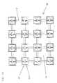
- FIG. 3is an incident-light-facing plan view of a VGMMRI according to a preferred embodiment of the present invention.
- FIG. 4is a portion of a perspective, stepped-sectional-view of the VGMMRI taken through sections A—A, and B—B of FIG. 3;
- FIG. 4Ais a plan view of another preferred embodiment of the VGMMRI wherein each microphotodetector pair with its gain adjustment layer is embedded in a lattice-like mesh and separated in space from each adjacent microphotodetector pair and its respective gain adjustment layer;
- FIGS. 5A-5Cillustrate the stages of fabrication for one preferred embodiment of the VGMMRI
- FIG. 6is a generalized schematic diagram of a modified Adaptive Imaging Retinal Stimulation System (AIRES), capable of use with the VGMMRI of FIGS. 3, 4 and 4 A;
- AIRESAdaptive Imaging Retinal Stimulation System
- FIGS. 7 A-Dshow a modified PTOS device suitable for use in the AIRES system of FIG. 6;
- FIG. 8shows the components of an alternative embodiment of the AIRES system of FIG. 6;
- FIG. 9is a perspective view of a retinal implant injector (RII) for use in implanting a retinal implant such as the VGMMRI of FIGS. 3, 4 , 4 A, and 5 A- 5 C;
- RIIretinal implant injector
- FIG. 10is a perspective view of a syringe retinal implant injector (SRI) assembly comprising the RII of FIG. 9 with a retinal implant inside, an attached cannula, and an attached operator controlled fluid filled syringe; and
- SRIretinal implant injector
- FIG. 11is a perspective view of an alternative embodiment of the SRI of FIG. 10 .
- the present inventionrelates to a retinal implant that can vary its stimulation voltage polarity and also produce higher stimulation voltages and currents to the retina compared to retinal implants of the prior art.
- This higher and adjustable stimulation voltage and currentallow for higher voltage and/or current stimulation thresholds that may be required to stimulate severely damaged retinal tissue.
- the implant stimulation voltages and currents of the present inventionare adaptable to the specific needs of a retina by the addition of regulated amounts of different wavelengths of projected images and background illumination light provided by a headset device that projects the different wavelengths into the eye. The use of this headset also allows the retinal implant to function in low light conditions.
- a retinal implant(also referred to herein as a variable gain multiphasic microphotodiode retinal implant or VGMMRI) 10 is positioned inside the eye 12 , in the subretinal space 16 , and is oriented to receive incident light 11 arriving through the cornea 13 and lens 14 of the eye 12 .
- the term lightrefers to visible and/or infrared light.
- FIG. 2a high magnification perspective sectional view shows the VGMMRI 10 placed in its preferred position in the subretinal space 16 .
- the layers of the retina from inside the eye to the outside in their respective positionsare: internal limiting membrane 18 ; nerve fiber layer 20 ; ganglion and amacrine cell layer 22 ; inner plexiform 24 ; inner nuclear layer 26 ; outer plexiform 28 ; outer nuclear layer 30 ; and photoreceptor layer rod and cone inner and outer segments 32 , all of which constitute the inner retina 34 .
- the VGGMRI 10is disposed between the inner retina 34 and the outer retina 40 comprised of the retinal pigment epithelium 36 and Bruch'membrane 38 . External to the outer retina 40 are the choriocapillaris 42 and choroidal vasculature 80 is the sclera 48 .
- FIG. 3is a incident-light-facing plan view of the VGMMRI 10 showing a top layer 60 of columns 61 of microphotodetector pairs 62 , that are preferably microphotodiode pairs constructed from an amorphos silicon material and arranged on the surface of a underlying gain layer formed from a silicon chip substrate.
- microphotodetectoris defined as any device capable of accepting light energy and converting it into an electrical signal, and/or current gain to the first strip-shaped PiN photodiode 66 that provides increased boltage and/or current gain to the first column 63 of the amorphous PiN microphotodetectors of the microphotodetector pairs 62 and a second strip-shaped NiP photodiode 68 that provides increase voltage and/or current gain to the second column 64 of the amorphous microphotodetectors pairs 62 .
- Each amprphous PiN microphotodetector 63 A and each amorphous NiP microphotodetector 64 A of each mircophotodetector pair 62has a common retinal stimulating electrode 65 .
- the N-portion common contact strip 66 A (FIG. 3) of the PiN microphotodetector column 63is in electrical contact with the P-portion of a first underlying strip-shaped PiN photodetector 66 .
- the common contact strip 66 Aextends the length of the column 61 and then beyond to the ends of the P-portion of the first strip-shaped PiN photodiode 66 .
- the purpose of this first underlying strip-shaped PiN photodetector 66is to provide increased voltage and/or current gain to the overlying PiN microphotodetectors 63 A.
- the P-portion common contact strip 68 A of the amorphous NiP microphotodetector column 64(FIG. 3) is in electrical contact with the N-portion of the second underlying strip-shaped NiP photodetector 68 .
- the common contact strip 68 Aextends the length of the column 61 and then beyond to the ends of the N-portion of the second strip-shaped NiP photodiode 68 .
- the purpose of this second underlying strip-shaped Nip photodetector 68is to provide increased voltage and/or current gain to the overlying amorphous NiP microphotodetectors 64 A.
- each VGMMRI pixel 62may be fabricated as an individual pixel, physically separated in space from another pixel 62 , but then commonly embedded in a lattice-like mesh 17 with other pixels 62 .
- the purpose of this mesh structureis to allow nourishment to flow between the inner and outer retina through the channels of the mesh.
- FIG. 4a stepped sectional view taken through a portion of the sections A—A and B—B of FIG. 3 further illustrates a preferred embodiment of the VGMMRI 10 .
- FIG. 4best shows the upper microphotodetector pixel layer 60 for receiving incident light images 11 , and the voltage and/or current gain adjustment layer 100 .
- the microphotodetector pixel layer 60 of the VGMMRI 10is stacked on top of the voltage/current gain adjustment photodiode layer 100 and the two layers 60 , 100 are electrically connected in series.
- the microphotodetector pixels of the upper layer 60are formed of an amorphous silicon material and the gain adjustment layer 100 is composed of photodetector strips formed of a crystalline silicon material.
- the gain adjustment layer 100preferably has a greater area than the area of the microphotodetector pixel layer 60 so that a portion of the gain adjustment layer 100 extends out beyond the perimeter of the microphotodetector layer 60 .
- the upper microphotodetector layer 60covers approximately 80% of the gain adjustment layer 100 and is centered on the gain adjustment layer 100 such that the portion of the gain adjustment layer extending beyond the perimeter of the microphotodetector layer 60 is exposed to incident light.
- the gain adjustment layer 100may also have the same area as microphotodetector layer 60 ; in this case, incident light 11 of a selected range of wavelengths pass through microphotodetector layer 60 to reach the lower gain adjustment layer 100 . This result is achieved by taking advantage of the property of amorphous silicon to block certain wavelengths of visible light and pass certain wavelengths of infrared light.
- the microphotodetector pixel layer 60is made up of individual pixels 62 preferably constructed of an amorphous PiN 63 A and an amorphous NiP 64 A microphotodetector oriented so that the N portion 80 of each NiP microphotodetector 64 A is adjacent the P portion 76 of each PiN microphotodetector 63 A, and the P portion 76 A of each NiP microphotodetector 64 A is adjacent the N portion 80 A of each PiN microphotodetector 63 A.
- An intrinsic layer 78is between the P portions and N portions of each microphotodetector 63 A and 64 A.
- the P portions 76 , 76 A, intrinsic layer 78 , and N portions 80 , 80 A, of the microphotodetectors 63 A and 64 Aare all preferably fabricated from amorphous silicon (a:Si), but may also be made from other photodetector materials well known to one skilled in the art.
- the VGMMRI 10may be fabricated by laminating two membranes of crystalline silicon (Silicon) microphotodetectors together to produce a similar structure to the preferred embodiment of this invention. This would be analogous to a multilayer PC board sandwiched together like a piece of plywood. The laminated membranes of crystalline silicon microphotodetectors would require interlayer connections and thin substrate 3-D silicon processing.
- Amorphous siliconcan be used to fabricate a very thin device. Also, amorphous silicon and has strong light absorbing capability in the visible range which can add to the efficiency of photodetector devices made with this material. Crystalline silicon, however, possesses more desirable electrical leakage qualities than amorphous silicon that may prove advantageous in higher operating voltage implementations of a microphotodetector. This latter fact, however, is more of an issue with higher operating voltages than in self-biased operation.
- a laminated crystalline silicon structurecan also produce very smooth pixel structures.
- Layer 77is a lattice-like light block fabricated from an opaque material, preferably a suitable thickness of platinum, that prevents cross-talk between pixels 62 of microphotodetector pairs.
- Each pixel 62has electrode metallization 65 that connects adjacent PiN 63 A and NiP 64 A microphotodetectors.
- the formed inner electrode 81electrically connects the P-side 76 of the PiN microphotodetector 63 A with the adjacent N-side 80 of the NiP microphotodetector 64 A. All PiN microphotodetectors 63 A within the same column of pixels of FIG. 3, share a common lower electrode strip 150 . Likewise all NiP photodetectors 64 A within the same column of pixels 64 of FIG. 3, share a common lower electrode strip 83 .
- the upper electrode 65has a first upper layer 86 of sputtered iridium/iridium oxide deposited on second upper layer 88 of platinum.
- the second upper layer 88is deposited on a first inner layer 170 of platinum formed over a second inner layer 92 of titanium.
- the first inner platinum layer 170is very thin and is semitransparent to light. It is deposited over another very thin second inner layer of semitransparent titanium 92 that forms a silicon adhesion layer to prevent titanium oxidation and to ensure proper surface conductivity.
- the second upper layer of platinum 88is thicker and serves as the buildup metal for the final retinal stimulation electrode 65 completed by deposition of an iridium/iridium oxide layer 86 over the platinum layer 88 .
- the formed inner electrodes 81 ; of microphotodetector pairs 62are separated from each other by an insulating cap of silicon dioxide 82 having an opening for the retinal stimulation electrode 65 .
- the semitransparent titanium second inner layer 92preferably contacts almost all of the surfaces of the adjacent P portion 76 and N portion 80 areas of the microphotodetectors 63 A, 64 A. It is noted that a metal contact surface is preferred that contacts as much of the active areas of each microphotodetector as possible to extract proper electrical current. This is because electron mobility can be limited in amorphous silicon and photon generated electrons in the depletion region may not travel far in the amorphous silicon material.
- the PiN microphotodetector 63 A in each microphotodetector pixel 62includes, preferably, a visible-light pass filter 74 designed to allow a portion of visible light spectrum to pass through to excite the PiN-oriented microphotodetector 63 A while blocking other wavelengths, including infrared light. In other embodiments, a light pass filter for other wavelengths of visible or infrared light would also be suitable.
- the NiP microphotodetector 64 A of each microphotodetector pixel 62includes preferably an infrared-light pass filter (IR-A) 75 to permit a portion of the infrared light spectrum to pass through to excite the NiP oriented microphotodetector 64 A while blocking visible light.
- IR-Ainfrared-light pass filter
- a suitable material for the IR-A pass filter 75 and the visible light pass filter 74is an interference type filter material, although other filter types, well known to one skilled in the art, would also be suitable.
- FIGS. 3 and 4illustrate a microphotodetector pixel layer 60 with pixels 62 made up of paired PiN 63 A and NiP 64 A microphotodetectors having a particular structure
- MMRImulti-phasic microphotodetector retinal implant
- the gain adjustment layer 100has alternating columns of PiN 66 and NiP 68 voltage/current gain photodetector strips.
- Each PiN 66 and NIP 68 photodetector stripis preferably a single crystalline photodetector that spans the cord of the VGMMRI 10 at its particular position.
- a portion of all PiN photodetector strips 66is in electrical contact with the common platinum electrode strips 150 of the PiN columns of the amorphous microphotodetector pixel layer 60 via a titanium adhesion layer 160 .
- a portion of all NiP photodetector strips 68are in electrical contact with the common platinum electrode strips 83 of the amorphous microphotodetector pixel layer 60 via a titanium adhesion layer 98 .
- a crystalline silicon substrate 200which is an N properties substrate, is preferably the starting material of gain layer 100 .
- the substrate 200is fabricated on the top side (amorphous silicon side) with alternating P-doped (P+) strips 154 and N-doped (N+) strips 155 .
- the bottom side of gain layer 100is processed with alternating N-doped (N+) strips 152 and P-doped (P+) strips 153 , where N+ diffusion 152 is physically aligned with the P+ diffusion 154 , and the P+ diffusion 153 is physically aligned with the N+ diffusion 155 .
- Adjacent photodiode strips of PiN 66 and NiP 68 structuresare isolated by N+ isolation channel 151 that penetrates the gain layer 100 from both sides, preferably merging in the middle of gain layer 100 .
- trench isolationwhich is well known to one skilled in the art, can also be used to isolate the photodiode strips 66 , 68 .
- the strips 66 , 68are aligned in parallel, in an alternating pattern, with the common electrode strips 150 , 83 of the amorphous silicon microphotodetector layer 60 .
- Each PiN crystalline silicon photodetector strip 66is lined up with a respective column of PiN amorphous silicon microphotodetector pixel elements 63 A above the common electrode strip 150
- each NiP crystalline silicon photodetector strip 68is lined up with a respective column of NiP amorphous silicon pixel elements 64 A above the common electrode strip 83 .
- This matching alignmentcreates a desired series electrical connection of amorphous silicon pixels 63 A, 64 A with their respective silicon photodetectors 66 , 68 in the gain adjustment layer 100 .
- the portions of the PiN and NiP strips 66 , 68 extending past the perimeter edge of the microphotodetectors 62are coated with an infrared-light pass filter (IR-B) 106 .
- the IR-B filter 106is preferably designed to pass a different bandwidth of infrared light than the IR-A filter 75 on the NiP microphotodetectors 64 A of the amorphous silicon microphotodetector pixel layer 60 .
- a bottom-side electrode 114on the bottom side of the VGMMRI 10 , preferably covers the entire bottom portion of the gain adjustment layer 100 .
- the bottom-side electrode 114which is preferably made of an iridium/iridium oxide coating 118 deposited over a titanium layer 116 , extends over the entire bottom side of the VGMMRI 10 to allow even current distribution across the “ground” plane of the VGMMRI device 10 .
- the bottom-side titanium layer 116directly contacts all the P+ layers 153 and N+ layers 152 .
- the upper and lower electrodes 65 , 114 of the VGMMRI 10preferably utilize a titanium layer 88 , 116 to maintain proper adhesion and electrical continuity between the silicon (amorphous or crystalline) and the sputtered iridium/iridium oxide layers 86 , 118 .
- the top amorphous silicon microphotodetector layer 60is approximately 4000 angstroms in thickness.
- the N-amorphous silicon (N+ a-Si:H) 80 , 80 A and P-amorphous silicon (P+ a-Si:H) 76 , 76 A layersare approximately 150 angstroms thick, while the thicker intrinsic-amorphous silicon (undoped a-Si:H) layer 78 in the middle is approximately 3600 angstroms.
- the thickness for the gain adjustment layer 100is approximately 15 micrometer ( ⁇ m) and the bottom side titanium layer 116 and iridium/iridium oxide layer 118 of the lower electrode 114 adding approximately 150 angstroms and 600 angstroms, respectively.
- each amorphous microphotodetector pixel 62is an 11 ⁇ m by 11 ⁇ m square. In this configuration, each NiP 64 A and PiN 63 A segment is preferably 5.5 ⁇ m by 11 ⁇ m. This size and shape of each microphotodetector pixel 62 is preferable because the retinal stimulation electrode center-to-center spacing in the VGMMRI 10 then approaches the resolution pitch of the human retina. Because of the lower fill factor in each pixel 62 as the geometries of the pixel becomes smaller, more light flux is necessary to maintain a give current flux. The VGMMRI 10 , however, can drive a current density more evenly through the retina by its ability to increase voltage and current gain for an entire area or for an individual pixel.
- the term fill factorrefers to the area of each pixel “filled” by incoming light. The fill factor is proportional to the total amount of photoactive surface relative to the amount of the photoactive surface blocked by the stimulating electrode and any other structures.
- the VGMMRI implant 10may be used in an eye to treat an area of outer retina and/or limited inner retina dysfunction.
- the shape of the implantmay be fabricated to resemble the shape of that area. Shapes such as a disk, an annular disk, a partial annular disk, or irregular shapes are useful and readily fabricated by one skilled in the art.
- the VGMMRI device 10 Ais fabricated as an array whose pixel blocks 62 A are preferably comprised of 1 to 9 microphotodetector sub-pixels 62 , in 1 ⁇ 1, 2 ⁇ 2 or 3 ⁇ 3 blocks, that are then plurally secured in an even pattern in a mesh-like lattice 17 .
- the mesh-like lattice 17is preferably made of a flexible biocompatible material such as silicon of Parylene.
- the embodiment of FIG. 4Ashows 1 ⁇ 1 pixel blocks 62 A.
- the openings 18 in the mesh-like lattice 17allow nourishment, nutrients, oxygen, carbon dioxide, and other biological compounds to pass readily between the inner retina (neurosensory retina) and the outer retina ( retinal pigment epithelium) and are beneficial to the retina.
- This mesh-like lattice 17 designthus aids the biocompatibility of the VGMMRI device. 10 A.
- a VGMMRIis preferably fabricated using silicon on insulator (SOI) wafers known in the art.
- SOIsilicon on insulator
- the top sideis processed first, followed by a back etch of the support portion of the SOI wafer. This etch will automatically stop at the SOI oxide layer interface. Removal of this oxide layer will reveal the bottom side of the silicon membrane ready for further processing.
- the suitable thickness of the silicon membraneis from approximately 2 to 50 microns. Standard ion implantation and diffusion techniques are used to produce active regions on both sides of the silicon membrane.
- FIG. 5Ashows a portion of the silicon membrane 200 that is to be processed into two VGMMRI pixels with P+ active regions 154 , 153 and N+ active regions 152 , 155 with N+ channel stop regions 151 driven in from the top and bottom sides.
- the active regions on the bottom sidehave a complimentary pattern to that of the top side.
- FIG. 5Bshows continuation of the fabrication process with deposition approximately 50 angstroms of platinum over 50 angstroms of titanium for the base metal 66 A, 68 A, on the top side and patterning this metal layer 66 A, 68 A to form the foundation for the amorphous silicon layer.
- P+a-Si:H 76 Ais deposited to a thickness of approximately 150 angstroms on the top side and patterned to match the Pt/Ti pattern 68 A only over the N+ regions 155 as shown in FIGS. 5A, 5 B.
- approximately 150 angstroms of N+a-Si:H 80 Ais deposited and patterned to match the Pt/Ti pattern 66 A only over the P+ regions 154 as shown in FIGS. 5A, 5 B.
- a sacrificial 0.1 micrometer thick protective aluminum layersuch as is commonly used in the art, is used to protect existing features whenever this is required in patterning.
- Approximately 3700 angstroms of undoped a-Si:H 78is then deposited over all features. This layer will become the intrinsic layer of the PiN and NiP microphotodiodes in the amorphous silicon side of the finished VGMMRI device.
- approximately 100 angstroms of N+a-Si:H 80is now deposited and patterned only over P+a-Si:H areas 76 A.
- approximately 100 angstroms of P+a-Si: H 76is deposited and patterned over the N+a-Si:H 80 A areas.
- FIG. 5Cshows the final stages in the fabrication of the VGMMRI pixels 62 .
- the top transparent electrode 81 of each amorphous photodiode pixel 62is fabricated by depositing approximately 50 angstroms of platinum over 50 angstroms of titanium and patterning the electrode 81 to match each PiN 63 A and NiP 64 A amorphous silicon structure of the pixel 62 , also shown in FIG. 5 B.
- the filters for the amorphous and crystalline PiN and NiP photodiodesare formed next.
- the fabrication of filters over only one of the VGMMRI pixels 62is described.
- a protective aluminum mask layeris deposited on the top side and the aluminum is etched away over the PiN amorphous silicon microphotodiode 63 A of FIG. 5C, and visible light pass dielectric filter material 74 is deposited and then patterned to remain only within these openings.
- the aluminum maskis now etched away and a fresh aluminum mask is deposited.
- the IR-A light pass filter 75 over the NiP amorphous silicon microphotodiode 64 Ais formed.
- a platinum layer of 0.5 micrometersis deposited and patterned on the amorphous silicon PiN/NiP electrode area to begin the formation of the electrode 65 .
- the electrode 65is completed by patterning, using photoresist lift-off, approximately 150 angstroms of platinum followed by approximately 600 angstroms of iridium/iridium oxide.
- the IR-B light pass dielectric filter layer 106is now deposited and patterned over only the light facing portions of the crystalline silicon PiN and NiP photodiodes using the same aluminum protective layer process followed by selective etching and removal as already described.
- an insulation layer of silicon dioxide 116is patterned between the bottom crystalline silicon P portion 153 and the bottom crystalline silicon N portion 152 .
- approximately 150 angstroms of titanium, followed by approximately 600 angstroms iridium/iridium oxideare deposited on the bottom side to form the rear electrode 118 .
- This bottom electrode 118 of each VGMMRI pixel 62can either be electrically isolated or electrically connected to the electrodes 118 of other VGMMRI pixels 62 , in the latter case to form a common ground electrode plane in another embodiment of the VGMMRI device.
- a channel 23is created between the VGMMRI pixels 62 using reactive ion etching that etches entirely through most to all of the intervening area of crystalline silicon substrate 200 , IR-B filter 106 , and back electrode 118 .
- silicon bridgesremain in some areas between the VGMMRI pixels 62 .
- the VGMMRI pixels 62are retained in position by the silicon bridges in this case.
- the VGMMRI pixels 62are embedded in a lattice-like, flexible, biocompatible mesh that has been previously described.
- amorphous silicon by itselfmay be used to fabricate the VGMMRI device.
- amorphous silicon by itselfmay be used to fabricate the VGMMRI device.
- FIG. 5Calthough the same IR-B filter 106 is used in a preferred embodiment to cover the PiN and NiP gain photodiodes of the crystalline silicon, in other embodiments, different filters, each passing a different portion of IR-B light, are used to cover the PiN and NiP gain photodiodes respectively. These other embodiments provide greater control over the amount of voltage and current gain provided by the gain photodiodes by allowing individual wavelength portions of IR-B light to control the gain of the PiN or NiP gain photodiode.
- an advantage of the disclosed VGMMRI 10 in FIGS. 3-5is that voltage and current gain of the VGMMRI 10 can be controlled. In one preferred embodiment, this gain is controllable for the entire implant 10 and useable by any of the microphotodetector pixels 62 .
- the VGMMRI 10When implanted in the subretinal space of the eye, the VGMMRI 10 receives the light of images implanted in the subretinal space. Photovoltaic potentials are generated at each pixel electrode 65 in proportion to the intensity of the incident light. These photovoltaic potentials are retinotopically disturbed in the shape of the incident images and produce charges at the iridium/iridium oxide electrodes 65 to the overlying retinal cells and structure 34 is both resistive and capacitive.
- the charge developed at the electrode 65is either positive or negative.
- a positive chargecauses the contacting overlying cell structure 30 , 32 of FIG. 2, to produce a sensation of darkness through depolarization of cell membranes, while a negative charge causes a sensation of light through hyperpolarization of cell membranes.
- an advantage of the preferred iridium/iridium oxide electrode of this inventionis that it supports better DC ionic flow into tissue in addition to having a higher capacitive effect than is possible with other electrode materials such as platinum. This results in lower work function for the VGMMRI 10 and thus the VGMMRI operates with lower electrode potentials. The lower electrode potentials result in better low light performance and lessen potential electrolysis damage to ocular tissues. Secondly, the larger capacitive effect of the preferred iridium/iridium electrode of the VGMMRI, 10 provides a passive charge balance effect to the tissues during capacitive discharge of the electrode during the moments when light is absent.
- the amount of light available at the VGMMRI 10may be low, or the electric stimulation threshold of the retina overlying the implant may be high. In either case, additional voltage and/or current gain is necessary to stimulate the surviving cell layers and/or structures.
- the VGMMRI 10 embodiment of this inventionachieves the desired gain by stacking two layers of microphotodetectors in series to achieve up to twice the voltage swing. The resultant higher voltage drives a higher current through the tissues.
- the amorphous microphotodetector pixel layer 60is stacked onto the crystalline PiN/NiP microphotodetector strips 66 A, 68 A of the gain adjustment layer 100 .
- the layers 60 , 100are stacked such that the pixels 62 and their respective PiN and NiP contact strips 66 A, 68 A in the gain adjustment layer 100 are connected in series with the underlying photodetectors 66 , 68 .
- twice the positive or negative voltage swingmay be attainable as compared to the voltage swing attainable with just the single top PiN/NiP microphotodetector layer 60 .
- the filters 74 , 75 , 106 on the VGMMRI 10allow for control of how much gain is obtained and where that gain is distributed by allowing different wavelengths of light to preferentially stimulate different microphotodetectors under each filter.
- the filters 74 , 75 and 106are fabricated so that each of the three filters pass a different wavelength, or range of wavelengths of visible and/or infrared light.
- the IR-A and IR-B filters 75 , 106are selected to pass a portion of wavelengths in the range of 400 nanometers to 2 microns.
- the IR-B filters 106are selected to pass a portion of wavelengths in the range of 800 nanometers to 2 microns and the IR-A filters 75 are selected to pass a portion of wavelengths in the range of 400 nanometers to 2 microns.
- the visible light pass filters 74are preferably selected to pass a portion of wavelengths in the range of 400 nanometers to 2 microns, and more preferably in the range of 400 to 650 nanometers.
- the different wavelengths of lightmay enter the eye from the environment and/or from another external source such as the headset discussed below with respect to FIGS. 6 and 7.
- the portions of the PiN and NiP strips 66 , 68 of the gain adjustment layer 100 extending outside the perimeter of the pixel layer 60are coated with the IR-B 106 filter, wavelengths that pass through the IR-B filter are used to selectively provide power to the gain layer 100 which in turn provides the additional voltage and current gain to the overlying microphotodetector layer 60 .
- Both the PiN microphotodetectors 63 A and the NiP microphotodetectors 64 Amay utilize this reservoir of power from the gain layer 100 . The foregoing mechanism allows the microphotodetectors 63 A and 64 A to generate higher voltages and current than they would otherwise generate if not for the underlying gain layer 100 .
- one of the microphotodetectors 63 A, 64 Ais more sensitive to visible light and the other more sensitive to IR-A light, respectively, light of these two predominant wavelengths will generate sensations of light and darkness in the overlying retinal layers; a positive potential at electrode 65 will produce a sensation of darkness, and a negative potential a sensation of light.
- This mechanismis described in greater detail in U.S. Pat. No. 6,230,057 and in U.S. Pat. No. 5,895,415, the disclosures of each are incorporated by reference herein.
- the VGMMRI implant 10has a rectangular microphotodetector pixel top layer 60 centered overlying a larger area gain adjustment layer 100 so that approximately 80% of the gain adjustment layer 100 is covered by layer 60 and the remaining 20% of layer 100 is exposed to incident light. Although only 20% of the gain adjustment layer 100 is exposed in this embodiment, smaller or larger percentages of exposed area may be fabricated in other embodiments.
- the VGMMRI 10has a gain adjustment layer integrated into each pixel 62 and both are physically separated in space from other pixels 62 .
- This configurationallows individual VGMMRI pixels 62 to be embedded, as shown, within a lattice-like mesh 17 .
- the lattice-like mesh 17is also configurable to have a common ground electrode for all the pixels 62 .
- the visible, IR-A, and IR-B light power supply to the VGMMRI 10is optionally provided by an external headset system in addition to the visible, IR-A, and IR-B provided by an external headset system in addition to the visible, headset system 230 , the so-called AIRES-M system 230 of FIGS. 6, 7 , 8 , is a modification of the PTOS headset of the Adaptive Imaging Retinal Stimulation System (AIRES) of U.S. Pat. No. 5,895,415.
- AIRESAdaptive Imaging Retinal Stimulation System
- the AIRES-M 230includes component sub-systems of a Projection and Tracking Optical System (PTOS) headset 232 , a Neuro-Net Computer (NNC) 234 , an Imaging CCD Camera (IMCCD) 236 and an Input Stylus Pad (ISP) 238 .
- PTOSProjection and Tracking Optical System
- NNCNeuro-Net Computer
- IMCDImaging CCD Camera
- ISPInput Stylus Pad
- a Pupil Reflex Tracking CCD (PRTCCD) 242that has incorporated an IR-B LED display (IRBLED) 240 , and a visible/IR-A LED display (VISIRALED) 241 , are positoned inside the PTOS 232 .
- a VGMMRI 10is shown in the subretinal space of the eye 12 .
- IR-A and visible light images form the VISIRALED 241 within the PTOS 232are optically projected into the eye 12 , when necessary, for example, during periods of low ambient lighting.
- IR-B Illumination from the IRBLED 240is also projected into the eye when necessary to power the voltage and current gain of layer 100 from FIG. 4 .
- Light intensity, duration, wavelength balance, and pulsing frequency of the VISIRALED 241 and IRBLED 240is controlled by the NNC 234 and modulated by patient inputs via the interfaced ISP 238 .
- the IMCCD 236which is mounted on or in the PTOS headset 232 , provide the image inputs to the NNC 234 which in turn programs the visible, IR-A, and IR-B outputs of the VISIRALED 241 and IRBLED 240 .
- a PRTCCD 242is integrated into the PTOS headset 232 to track eye movements via changes in the position of the pupillary Purkinje reflexes.
- the PRTCCD 242outputs to the NNC 234 which in turn shifts the position of projected images from the VISIRALED 241 via electronic control to follow the eye movements.
- the PTOS 232is also programmable to provide just diffuse IR-B illumination to the VGMMRI 10 without projecting visible or IR-A images.
- the PTOS 232is also programmable via the NNC 234 to project patterned IR-B light onto various VGMMRI pixels in the embodiment where the gain adjustment layer 100 is integrated into each of the VGMMRI pixels and the VGMMRI pixels are separated in space and embedded in a lattice-like mesh.
- FIGS. 7A-7Dshow a glasses-like configuration 232 of the PTOS component of the AIRES-M system 230 of FIG. 6 .
- FIG. 7Dalthough the schematic of the optical system differs somewhat from the generalized schematic of the PTOS component 232 demonstrated in FIG. 6, the spirit and function of both versions of the devices are the same.
- FIG. 7Ais a top view of the PTOS 232 . It shows the headpad 250 , the temple pieces 252 , and the ambient light intensity sensors 254 .
- FIG. 7Bis a front view of the PTOS 232 .
- FIG. 7Cis a phantom side view of the PTOS 232 . It shows an internal IR-A and visible light LED display light source 241 . Also shown is the partially reflective/transmissive mirror 248 , the supporting nose piece 256 , the headpad 250 , one of the temple pieces 252 , and the power supply and signal wire cable 258 leading to the NNC 234 of FIG. 6 .
- FIG. 7Dshows the VGMMRI 10 disposed in the subretinal space of the eye 12 with a focused image 246 .
- FIG. 8shows the components of the AIRES-M system, consisting of the PTOS 232 , the portable NNC 234 which may be secured to the patient's body, and the ISP 238 input device.
- a retinal implant injector (RII) 300may be used to place a retinal implant 302 into the vitreous cavity of the eye, or to place a retinal implant 302 directly into the subretinal space of the eye.
- the RII 300employs a fluid, which is placed inside the RII 300 , to push the retinal implant 302 to its exit at the terminal tip 304 of the RII 300 .
- controlled deposition of the retinal implant 302is possible without physically having to hold the retinal implant 302 with an instrument that can cause damage to the implant 302 .
- the RII 300is fabricated from tubing which is preferably made of Teflon (polytetrafluoroethylene) or Parylene and is transparent. It is flattened through most of its length with a taper 304 at the tip of its flattened end.
- the flattened cross-section 306preferably is similar to the cross-section of the retinal implant 302 .
- the opposite end of the tubemaintains a round cross-section 308 that allows the RII 300 to be inserted around a cannula 310 as shown in FIG. 10, that in turn is attached to a syringe 312 containing the fluid 314 used for the injection.
- the injection fluid 314is any biocompatible fluid but is preferably saline or a viscoelastic material.
- the retinal implant 302is first placed within the RII 300 .
- the RII 300is then attached around a cannula 310 that in turn is attached to a syringe 312 containing the preferred saline or viscoelastic fluid.
- the entire Retinal Injector Assembly 316is held by the operator via the syringe 312 .
- the tapered tip 304 of the RII 300is then advanced into the vitreous cavity of the eye through an opening made through the eye wall for this purpose.
- the retinal implant 302is pushed out of the RII 300 by fluid pressure exerted by operation of the fluid filled syringe 312 from outside the eye.
- the retinal implantis then manipulated with surgical instruments either to a position underneath the retina in the subretinal space, or on top of the retina in the epiretinal position.
- the RII 300is also useable to directly inject the retinal implant 302 through the retinotomy opening into the subretinal space. In this case, the tip 304 of the RII 300 is placed directly into the retinotomy opening before injection of the retinal implant 302 .
- a RII- 1 injector assembly 416utilizes an injector plunger 420 , placed within the injector 400 , to push the implant 402 out of the injector 400 .
- the injector plunger 420is shaped to conform to the inside cross-section of the injector 400 and is attached to any variety of well-known methods of moving the plunger 420 forward.
- a rod-like extension 425connects the injector plunger 420 to the syringe plunger 435 of a syringe 430 . Pushing the syringe plunger 435 thus pushes the injector plunger 420 forward and moves the implant 402 out of the injector 400 .
- a VGMMRI retinal implant having a multilayer structure of PiN and NiP microphotodiode pairsis disclosed in a structure allowing for voltage and current gain adjustment.
- the VGMMRI microphotodetector pixel structureis rectangular, although a round shape or other shapes may be implemented for the VGMMRI microphotodetector pixel structure, and easily fabricated by one ordinarily skilled in the art.
- the VGMMRI microphotodetector pixelsare fabricated as individual units separated in space and embedded in a lattice-like mesh. The mesh may also have a common conductor that contacts all the ground electrodes of the microphotodetector pixels on the mesh, providing a common ground plane.
Landscapes
- Health & Medical Sciences (AREA)
- Life Sciences & Earth Sciences (AREA)
- General Health & Medical Sciences (AREA)
- Veterinary Medicine (AREA)
- Engineering & Computer Science (AREA)
- Biomedical Technology (AREA)
- Public Health (AREA)
- Animal Behavior & Ethology (AREA)
- Ophthalmology & Optometry (AREA)
- Nuclear Medicine, Radiotherapy & Molecular Imaging (AREA)
- Radiology & Medical Imaging (AREA)
- Heart & Thoracic Surgery (AREA)
- Cardiology (AREA)
- Vascular Medicine (AREA)
- Prostheses (AREA)
- Transforming Light Signals Into Electric Signals (AREA)
- Solid State Image Pick-Up Elements (AREA)
- Stereo-Broadcasting Methods (AREA)
Abstract
Description
Claims (23)
Priority Applications (25)
| Application Number | Priority Date | Filing Date | Title |
|---|---|---|---|
| US09/539,399US6389317B1 (en) | 2000-03-31 | 2000-03-31 | Multi-phasic microphotodetector retinal implant with variable voltage and current capability |
| DE60143348TDE60143348D1 (en) | 2000-03-31 | 2001-03-15 | MULTIPHASE MICROPHOTODETECTION IMPLANT FOR RETINA WITH VARIABLE VOLTAGE AND CURRENT CAPACITY |
| MXPA02009564AMXPA02009564A (en) | 2000-03-31 | 2001-03-15 | Multi phasic microphotodetector retinal implant with variable voltage and current capability and apparatus for insertion. |
| BR0109661-3ABR0109661A (en) | 2000-03-31 | 2001-03-15 | Multiphase microphotodetector retinal implant with variable current and voltage capabilities and insertion device |
| CZ20023215ACZ20023215A3 (en) | 2000-03-31 | 2001-03-15 | Multi-phase microphotodetector retinal implant with variable voltage and current capability and apparatus for insertion thereof |
| CN01810400ACN1431921A (en) | 2000-03-31 | 2001-03-15 | Multi-phasic microphotodetector retinal implant with variable voltage and current capability and appts. for insertion |
| ES01916670TES2355204T3 (en) | 2000-03-31 | 2001-03-15 | MULTI PHASE MICROPHOTODETET RETINAL IMPLANT WITH CURRENT CAPACITY AND VARIABLE VOLTAGE. |
| HU0302846AHUP0302846A2 (en) | 2000-03-31 | 2001-03-15 | Multi-phasic microphodetector retinal implant with variable voltage and current capability and apparatus for insertion |
| JP2001572179AJP4393029B2 (en) | 2000-03-31 | 2001-03-15 | Retina transplantation and insertion device using multi-phase micro photoelectric detector with variable voltage current capability |
| KR1020027012752AKR20030025913A (en) | 2000-03-31 | 2001-03-15 | Multi-phasic microphotodetector retinal implant with variable voltage and current capability and apparatus for insertion |
| EP01916670AEP1267991B1 (en) | 2000-03-31 | 2001-03-15 | Multi-phasic microphotodetector retinal implant with variable voltage and current capability |
| IL15185101AIL151851A0 (en) | 2000-03-31 | 2001-03-15 | Multi-phasic microphotodetector retinal implant with variable voltage and current capability and apparatus for insertion |
| PCT/US2001/008232WO2001074444A1 (en) | 2000-03-31 | 2001-03-15 | Multi-phasic microphotodetector retinal implant with variable voltage and current capability and apparatus for insertion |
| RU2002126258/14ARU2002126258A (en) | 2000-03-31 | 2001-03-15 | AN IMPLANT BASED ON A MULTIPHASIC MICROPHOTODETECTOR FOR AN EYE NET WITH A VARIABLE VOLTAGE AND CURRENT AND A DEVICE FOR ITS INSERT |
| PL01365421APL365421A1 (en) | 2000-03-31 | 2001-03-15 | Multi-phasic microphotodetector retinal implant with variable voltage and current capability and apparatus for insertion |
| AU2001243665AAU2001243665B9 (en) | 2000-03-31 | 2001-03-15 | Multi-phasic microphotodetector retinal implant with variable voltage and current capability and apparatus for insertion |
| AT01916670TATE485796T1 (en) | 2000-03-31 | 2001-03-15 | MULTIPHASE MICROPHOTODETECTION IMPLANT FOR THE RETINA WITH VARIABLE VOLTAGE AND CURRENT CAPACITY |
| AU4366501AAU4366501A (en) | 2000-03-31 | 2001-03-15 | Multi-phasic microphotodetector retinal implant with variable voltage and current capability and apparatus for insertion |
| FI20021729AFI20021729A7 (en) | 2000-03-31 | 2001-03-15 | Multiphase microphotodetector implant for the retina with variable voltage and current, and device for insertion |
| CA2403618ACA2403618C (en) | 2000-03-31 | 2001-03-15 | Multi-phasic microphotodetector retinal implant with variable voltage and current capability and apparatus for insertion |
| US10/108,573US20020099420A1 (en) | 2000-03-31 | 2002-03-27 | Multi-phasic microphotodetector retinal implant with variable voltage and current capability and apparatus for insertion |
| ZA200207593AZA200207593B (en) | 2000-03-31 | 2002-09-20 | Multi-phasic microphotodetector retinal implant with variable voltage and current capability and apparatus for insertion. |
| NO20024612ANO20024612L (en) | 2000-03-31 | 2002-09-26 | Multiphase microphoto detector for retinal implant with variable voltage and current capability and insertion apparatus |
| US10/462,224US20040039401A1 (en) | 2000-03-31 | 2003-06-13 | Implant instrument |
| US10/690,413US7006873B2 (en) | 2000-03-31 | 2003-10-21 | Adjustment of electrical stimulus in a retinal implant |
Applications Claiming Priority (1)
| Application Number | Priority Date | Filing Date | Title |
|---|---|---|---|
| US09/539,399US6389317B1 (en) | 2000-03-31 | 2000-03-31 | Multi-phasic microphotodetector retinal implant with variable voltage and current capability |
Related Child Applications (1)
| Application Number | Title | Priority Date | Filing Date |
|---|---|---|---|
| US10/108,573DivisionUS20020099420A1 (en) | 2000-03-31 | 2002-03-27 | Multi-phasic microphotodetector retinal implant with variable voltage and current capability and apparatus for insertion |
Publications (1)
| Publication Number | Publication Date |
|---|---|
| US6389317B1true US6389317B1 (en) | 2002-05-14 |
Family
ID=24151041
Family Applications (3)
| Application Number | Title | Priority Date | Filing Date |
|---|---|---|---|
| US09/539,399Expired - LifetimeUS6389317B1 (en) | 2000-03-31 | 2000-03-31 | Multi-phasic microphotodetector retinal implant with variable voltage and current capability |
| US10/108,573AbandonedUS20020099420A1 (en) | 2000-03-31 | 2002-03-27 | Multi-phasic microphotodetector retinal implant with variable voltage and current capability and apparatus for insertion |
| US10/690,413Expired - LifetimeUS7006873B2 (en) | 2000-03-31 | 2003-10-21 | Adjustment of electrical stimulus in a retinal implant |
Family Applications After (2)
| Application Number | Title | Priority Date | Filing Date |
|---|---|---|---|
| US10/108,573AbandonedUS20020099420A1 (en) | 2000-03-31 | 2002-03-27 | Multi-phasic microphotodetector retinal implant with variable voltage and current capability and apparatus for insertion |
| US10/690,413Expired - LifetimeUS7006873B2 (en) | 2000-03-31 | 2003-10-21 | Adjustment of electrical stimulus in a retinal implant |
Country Status (21)
| Country | Link |
|---|---|
| US (3) | US6389317B1 (en) |
| EP (1) | EP1267991B1 (en) |
| JP (1) | JP4393029B2 (en) |
| KR (1) | KR20030025913A (en) |
| CN (1) | CN1431921A (en) |
| AT (1) | ATE485796T1 (en) |
| AU (2) | AU2001243665B9 (en) |
| BR (1) | BR0109661A (en) |
| CA (1) | CA2403618C (en) |
| CZ (1) | CZ20023215A3 (en) |
| DE (1) | DE60143348D1 (en) |
| ES (1) | ES2355204T3 (en) |
| FI (1) | FI20021729A7 (en) |
| HU (1) | HUP0302846A2 (en) |
| IL (1) | IL151851A0 (en) |
| MX (1) | MXPA02009564A (en) |
| NO (1) | NO20024612L (en) |
| PL (1) | PL365421A1 (en) |
| RU (1) | RU2002126258A (en) |
| WO (1) | WO2001074444A1 (en) |
| ZA (1) | ZA200207593B (en) |
Cited By (47)
| Publication number | Priority date | Publication date | Assignee | Title |
|---|---|---|---|---|
| US6507758B1 (en)* | 1999-03-24 | 2003-01-14 | Second Sight, Llc | Logarithmic light intensifier for use with photoreceptor-based implanted retinal prosthetics and those prosthetics |
| US20030158588A1 (en)* | 2002-01-17 | 2003-08-21 | Rizzo Joseph F. | Minimally invasive retinal prosthesis |
| US6611716B2 (en) | 1995-06-06 | 2003-08-26 | Optobionics Corporation | Multi-phasic microphotodiode retinal implant and adaptive imaging retinal stimulation system |
| US20030233126A1 (en)* | 2002-06-12 | 2003-12-18 | Alfred E. Mann Institute For Biomedical Engineering | Injection devices and methods for testing implants |
| US20040039401A1 (en)* | 2000-03-31 | 2004-02-26 | Chow Alan Y. | Implant instrument |
| DE10304831A1 (en)* | 2003-01-31 | 2004-08-26 | Eberhard-Karls-Universität Tübingen Universitätsklinikum | Retina implant to stimulate a retina depending on the light |
| US20040220652A1 (en)* | 2003-05-01 | 2004-11-04 | Zhou Dau Min | Adherent metal oxide coating forming a high surface area electrode |
| US20040236389A1 (en)* | 2003-05-01 | 2004-11-25 | Wolfgang Fink | Method and system for training a visual prosthesis |
| US20050004625A1 (en)* | 2001-06-29 | 2005-01-06 | Chow Alan Y. | Treatment of degenerative retinal disease via electrical stimulation of surface structures |
| US20050033202A1 (en)* | 2001-06-29 | 2005-02-10 | Chow Alan Y. | Mechanically activated objects for treatment of degenerative retinal disease |
| WO2005068014A1 (en)* | 2004-01-15 | 2005-07-28 | Iip-Technologies Gmbh | Neurological tool |
| US20050269606A1 (en)* | 2004-06-02 | 2005-12-08 | Chandra Mouli | Raised photodiode sensor to increase fill factor and quantum efficiency in scaled pixels |
| US20060074461A1 (en)* | 2004-07-23 | 2006-04-06 | Nidek Co., Ltd. | Visual restoration aiding device |
| US7031776B2 (en) | 2001-06-29 | 2006-04-18 | Optobionics | Methods for improving damaged retinal cell function |
| US7037943B2 (en) | 2001-04-10 | 2006-05-02 | Optobionics Corporation | Retinal treatment method |
| US20060148254A1 (en)* | 2005-01-05 | 2006-07-06 | Mclean George Y | Activated iridium oxide electrodes and methods for their fabrication |
| US20060173497A1 (en)* | 2005-02-01 | 2006-08-03 | Brian Mech | Micro-miniature implantable coated device |
| US7103416B2 (en)* | 2001-01-16 | 2006-09-05 | Second Sight Medical Products, Inc. | Visual prosthesis including enhanced receiving and stimulating portion |
| US7127301B1 (en) | 2003-04-28 | 2006-10-24 | Sandia Corporation | Flexible retinal electrode array |
| US20070265582A1 (en)* | 2002-06-12 | 2007-11-15 | University Of Southern California | Injection Devices for Unimpeded Target Location Testing |
| US20070284686A1 (en)* | 2006-06-09 | 2007-12-13 | Micron Technology, Inc. | Method of forming elevated photosensor and resulting structure |
| US20080046028A1 (en)* | 2006-08-15 | 2008-02-21 | Amie B Franklin | Systems and Methods for Treatment of Retinopathy and Other Eye Diseases |
| US20080066500A1 (en)* | 2006-09-15 | 2008-03-20 | Shun-Chang Su | Cable lock that is opened forcibly |
| US20080154365A1 (en)* | 2003-11-05 | 2008-06-26 | California Institute Of Technology | Method for integrating pre-fabricated chip structures into functional electronic systems |
| US20080228242A1 (en)* | 2003-05-01 | 2008-09-18 | California Institute Of Technology | Method and system for training a visual prosthesis |
| US20100204754A1 (en)* | 2009-02-09 | 2010-08-12 | Rainbow Medical Ltd. | Retinal prosthesis |
| US20100241060A1 (en)* | 2009-03-18 | 2010-09-23 | Roizman Keith | Surgical devices and methods |
| US20100249877A1 (en)* | 2007-11-21 | 2010-09-30 | The Trustees Of Boston College | Apparatus and Methods for Visual Perception Using an Array of Nanoscale Waveguides |
| US20110171320A1 (en)* | 2003-01-03 | 2011-07-14 | Marcos Dantus | Methods to extend vision to infrared wavelengths |
| US20110172736A1 (en)* | 2010-01-14 | 2011-07-14 | Nano-Retina, Inc. | Penetrating electrodes for retinal stimulation |
| US8428740B2 (en) | 2010-08-06 | 2013-04-23 | Nano-Retina, Inc. | Retinal prosthesis techniques |
| US8442641B2 (en) | 2010-08-06 | 2013-05-14 | Nano-Retina, Inc. | Retinal prosthesis techniques |
| US8571669B2 (en) | 2011-02-24 | 2013-10-29 | Nano-Retina, Inc. | Retinal prosthesis with efficient processing circuits |
| US8706243B2 (en) | 2009-02-09 | 2014-04-22 | Rainbow Medical Ltd. | Retinal prosthesis techniques |
| US20150246220A1 (en)* | 2012-05-09 | 2015-09-03 | Po-Kang Lin | Structure of Artificial Electronic Retina |
| EP2880430A4 (en)* | 2012-08-02 | 2016-04-27 | Univ California | INTEGRATED NANOWILE NETWORK DEVICES FOR DETECTION AND / OR APPLICATION OF ELECTRICAL SIGNALS TO A FABRIC |
| US9331791B2 (en) | 2014-01-21 | 2016-05-03 | Nano Retina Ltd. | Transfer of power and data |
| US9370417B2 (en) | 2013-03-14 | 2016-06-21 | Nano-Retina, Inc. | Foveated retinal prosthesis |
| US9381355B2 (en) | 2010-06-21 | 2016-07-05 | The Regents Of The University Of California | Ultra-high photosensitivity vertical nanowire arrays for retinal prosthesis |
| US9389431B2 (en) | 2011-11-04 | 2016-07-12 | Massachusetts Eye & Ear Infirmary | Contextual image stabilization |
| US9474902B2 (en) | 2013-12-31 | 2016-10-25 | Nano Retina Ltd. | Wearable apparatus for delivery of power to a retinal prosthesis |
| EP3461529A1 (en) | 2017-09-27 | 2019-04-03 | Pixium Vision SA | Tip, inserter attachment and delivery device |
| US11305118B2 (en) | 2018-11-30 | 2022-04-19 | Biovisics Medical, Inc. | Head worn apparatuses for vision therapy |
| US11338139B2 (en) | 2018-10-01 | 2022-05-24 | Biovisics Medical, Inc. | System and methods for controlled electrical modulation for vision therapy |
| US11471680B2 (en) | 2019-04-10 | 2022-10-18 | Biovisics, Inc. | Systems and interfaces for ocular therapy |
| US11511112B2 (en) | 2019-06-14 | 2022-11-29 | Biovisics Medical, Inc. | Wearable medical device |
| US12023498B2 (en) | 2019-07-12 | 2024-07-02 | Biovisics Medical, Inc. | Ocular therapy modes and systems |
Families Citing this family (30)
| Publication number | Priority date | Publication date | Assignee | Title |
|---|---|---|---|---|
| US8231637B2 (en)* | 2002-07-26 | 2012-07-31 | Second Sight Medical Products, Inc. | Surgical tool for electrode implantation |
| JP4204066B2 (en) | 2002-12-05 | 2009-01-07 | 保雄 田野 | Artificial vision system |
| CA2511908A1 (en)* | 2003-02-07 | 2004-08-26 | Optobionics Corporation | Implantable device using diamond-like carbon coating |
| US8078284B2 (en)* | 2004-05-25 | 2011-12-13 | Second Sight Medical Products, Inc. | Retinal prosthesis with a new configuration |
| JP4543152B2 (en)* | 2004-08-20 | 2010-09-15 | 独立行政法人産業技術総合研究所 | Transparent titanium-coated biocompatible material |
| JP2009533157A (en) | 2006-04-12 | 2009-09-17 | プロテウス バイオメディカル インコーポレイテッド | Embedded sealed structure without voids |
| JP4784757B2 (en)* | 2006-09-27 | 2011-10-05 | 学校法人 龍谷大学 | Artificial retina and manufacturing method thereof |
| US7905013B2 (en)* | 2007-06-04 | 2011-03-15 | Sharp Laboratories Of America, Inc. | Method for forming an iridium oxide (IrOx) nanowire neural sensor array |
| GB0913818D0 (en)* | 2009-08-07 | 2009-09-16 | Thermoteknix Systems Ltd | Light guiding device |
| JP5990103B2 (en) | 2009-12-23 | 2016-09-07 | アルコン リサーチ, リミテッド | Ophthalmic valved trocar cannula |
| US8343106B2 (en) | 2009-12-23 | 2013-01-01 | Alcon Research, Ltd. | Ophthalmic valved trocar vent |
| KR101925473B1 (en)* | 2010-10-27 | 2018-12-05 | 이리듐 메디칼 테크놀로지 컴퍼니 리미티드 | Flexible artificial retina devices |
| US9114004B2 (en) | 2010-10-27 | 2015-08-25 | Iridium Medical Technology Co, Ltd. | Flexible artificial retina devices |
| US8613135B2 (en) | 2011-05-06 | 2013-12-24 | National Tsing Hua University | Method for non-planar chip assembly |
| US9155881B2 (en) | 2011-05-06 | 2015-10-13 | Iridium Medical Technology Co, Ltd. | Non-planar chip assembly |
| TWI499407B (en)* | 2012-02-16 | 2015-09-11 | Univ Nat Chiao Tung | Artificial retinal prosthesis system and retinal chip |
| US10121533B2 (en) | 2012-11-21 | 2018-11-06 | Nano-Retina, Inc. | Techniques for data retention in memory cells during power interruption |
| US9720477B2 (en) | 2012-11-21 | 2017-08-01 | Nano-Retina, Inc. | Weak power supply operation and control |
| TW201544085A (en)* | 2014-05-16 | 2015-12-01 | Univ Nat Chiao Tung | An artificial retinal prosthesis system and an artificial retinal chip |
| EP3669932A1 (en)* | 2015-05-12 | 2020-06-24 | Pixium Vision SA | Photosensitive pixel structure with wrapped resistor |
| WO2016206809A1 (en) | 2015-06-24 | 2016-12-29 | Pixium Vision Sa | Photosensitive pixel structure with increased light absorption and photosensitive implant |
| TWI569817B (en)* | 2015-07-08 | 2017-02-11 | 國立交通大學 | Artificial retinal system, extraocular optics, and intraocular implanted wafers |
| EP3144032A1 (en) | 2015-09-15 | 2017-03-22 | Pixium Vision SA | Photosensitive pixel structure with front side coating |
| GB201613418D0 (en)* | 2016-08-03 | 2016-09-14 | Univ College Dublin Nat Univ Of Ireland Dublin | Retinal photoreceptor mosaic simulator |
| EP3618763A4 (en)* | 2017-05-08 | 2021-02-17 | Lambdavision Incorporated | RETINAL CELL STIMULATION AND VISION LOSS TREATMENT PROCESS |
| EP3427790A1 (en) | 2017-07-14 | 2019-01-16 | Pixium Vision SA | Photosensitive array |
| LU100467B1 (en) | 2017-09-22 | 2019-03-29 | Technische Univ Hamburg Harburg | Retina implant |
| WO2020107127A1 (en) | 2018-11-30 | 2020-06-04 | Ma Joseph J K | Ocular systems, devices, and methods |
| CN112451207B (en)* | 2020-12-10 | 2022-06-14 | 微智医疗器械有限公司 | Surgical instrument assembly for implanting a retinal implant |
| WO2022212053A1 (en)* | 2021-03-31 | 2022-10-06 | The Board Of Trustees Of The Leland Stanford Junior University | Photovoltaic retinal prosthesis with optically configurable confinement of electric field |
Citations (48)
| Publication number | Priority date | Publication date | Assignee | Title |
|---|---|---|---|---|
| US2760483A (en) | 1953-10-29 | 1956-08-28 | Tassicker Graham Edward | Retinal stimulator |
| DE1952937A1 (en) | 1968-10-21 | 1970-06-25 | Armand Kastner | On vertical posts, rods or the like. clampable holder |
| US3594823A (en) | 1969-02-11 | 1971-07-27 | Patent Management Inc | Visual substitution system with receptor scanning means |
| US3628193A (en) | 1969-02-19 | 1971-12-21 | Inst Of Medical Sciences The | Tactile image projection system |
| US3766311A (en) | 1972-04-26 | 1973-10-16 | H Boll | Sensory substitution system |
| US3848608A (en) | 1973-07-23 | 1974-11-19 | Gen Electric | Subject integument spatial stimulator |
| US3914800A (en) | 1974-06-06 | 1975-10-28 | Inst Of Medical Sciences | Fluid mechanical tactile oscilloscope to augment the five senses |
| US4001867A (en) | 1974-08-22 | 1977-01-04 | Dionics, Inc. | Semiconductive devices with integrated circuit switches |
| US4211474A (en) | 1977-01-31 | 1980-07-08 | Compagnie Generale D'electricite | Ultra-rapid electro-optical shutter |
| US4251887A (en) | 1979-04-02 | 1981-02-24 | Anis Aziz Y | Posterior chamber capsular lens implant and method for implantation of the lens |
| US4272910A (en) | 1979-07-31 | 1981-06-16 | Danz W R | Ocular prosthetic or the like |
| EP0084621A2 (en) | 1982-01-22 | 1983-08-03 | International Business Machines Corporation | Semiconductor signal conversion device using photon coupling |
| US4551149A (en) | 1982-02-16 | 1985-11-05 | Michael Sciarra | Prosthetic vision system |
| US4600004A (en) | 1982-09-08 | 1986-07-15 | Osvaldo Lopez | Intraocular lens holder and inserter |
| US4601545A (en) | 1984-05-16 | 1986-07-22 | Kern Seymour P | Variable power lens system |
| US4628933A (en)* | 1985-07-23 | 1986-12-16 | Michelson Robin P | Method and apparatus for visual prosthesis |
| US4679572A (en) | 1986-03-11 | 1987-07-14 | Intermedics, Inc. | Low threshold cardiac pacing electrodes |
| EP0233789A2 (en) | 1986-02-21 | 1987-08-26 | THE COOPER COMPANIES, INC. (formerly called CooperVision, Inc.) | Tool for inserting an intraocular lens |
| US4810050A (en) | 1985-05-24 | 1989-03-07 | British Telecommunications Public Limited Company | Optical inverter and logic devices using same with buffer limited electrical interface |
| US4832202A (en) | 1986-05-22 | 1989-05-23 | General Foods Limited | Containers |
| US4873448A (en) | 1986-04-30 | 1989-10-10 | Omron Tateisi Electronics Co. | Input circuit having a photo-coupler with bi-directional indicator |
| GB2229543A (en) | 1988-12-26 | 1990-09-26 | Mitsubishi Mining & Cement Co | Photo-driven optical switch |
| US4978842A (en) | 1989-04-21 | 1990-12-18 | At&T Bell Laboratories | Programmable optical logic device with complementary inputs |
| US5016633A (en) | 1989-08-08 | 1991-05-21 | Chow Alan Y | Artificial retina device |
| US5024223A (en) | 1989-08-08 | 1991-06-18 | Chow Alan Y | Artificial retina device |
| US5109844A (en) | 1990-10-11 | 1992-05-05 | Duke University | Retinal microstimulation |
| US5130528A (en) | 1991-03-01 | 1992-07-14 | International Business Machines Corporation | Opto-photo-electric switch |
| US5130776A (en) | 1989-03-16 | 1992-07-14 | Landis & Gyr Betriebs Ag | Ultraviolet-light photodiode |
| US5159927A (en) | 1989-07-26 | 1992-11-03 | Ferdinand Schmid | Visual prosthesis apparatus and method |
| US5223728A (en) | 1992-04-02 | 1993-06-29 | Motorola, Inc. | Optical switch integrated circuit |
| US5256882A (en) | 1991-09-17 | 1993-10-26 | Kabushiki Kaisha Toshiba | Signal transmission circuit having a latch-up function |
| US5338991A (en) | 1992-12-28 | 1994-08-16 | Lu Chao Cheng | High power solid state relay with input presence and polarity indication |
| US5351309A (en) | 1992-06-30 | 1994-09-27 | National Science Council | Image edge sensor |
| US5397350A (en) | 1993-05-03 | 1995-03-14 | Chow; Alan Y. | Independent photoelectric artificial retina device and method of using same |
| US5411540A (en) | 1993-06-03 | 1995-05-02 | Massachusetts Institute Of Technology | Method and apparatus for preferential neuron stimulation |
| US5476494A (en) | 1992-09-11 | 1995-12-19 | Massachusetts Institute Of Technology | Low pressure neural contact structure |
| US5491349A (en) | 1991-06-13 | 1996-02-13 | Kabushiki Kaisha Toshiba | Multi-color light emitting device |
| US5556423A (en) | 1993-05-03 | 1996-09-17 | Alan Y. Chow | Independent photoelectric artificial retina device and method of using same |
| US5648655A (en) | 1992-09-30 | 1997-07-15 | Lsi Logic Corporation | Sensing device for capturing a light image |
| US5717201A (en) | 1996-04-18 | 1998-02-10 | National Science Council | Double four-quadrant angle-position detector |
| US5865839A (en) | 1996-12-30 | 1999-02-02 | Doorish; John F. | Artificial retina |
| US5895414A (en)* | 1996-04-19 | 1999-04-20 | Sanchez-Zambrano; Sergio | Pacemaker housing |
| US5895415A (en) | 1995-06-06 | 1999-04-20 | Optobionics Corporation | Multi-phasic microphotodiode retinal implant and adaptive imaging retinal stimulation system |
| US5935155A (en) | 1998-03-13 | 1999-08-10 | John Hopkins University, School Of Medicine | Visual prosthesis and method of using same |
| US5944747A (en) | 1998-03-13 | 1999-08-31 | Johns Hopkins University | Method for preferential outer retinal stimulation |
| US6032062A (en) | 1995-08-10 | 2000-02-29 | Nmi Naturwissenschaftliches Und Medizinisches Institut | Microelectrode arrangement |
| US6035236A (en) | 1998-07-13 | 2000-03-07 | Bionergy Therapeutics, Inc. | Methods and apparatus for electrical microcurrent stimulation therapy |
| US6230057B1 (en)* | 1995-06-06 | 2001-05-08 | Optobionics Corporation | Multi-phasic microphotodiode retinal implant and adaptive imaging retinal stimulation system |
Family Cites Families (9)
| Publication number | Priority date | Publication date | Assignee | Title |
|---|---|---|---|---|
| US4681102A (en) | 1985-09-11 | 1987-07-21 | Bartell Michael T | Apparatus and method for insertion of an intra-ocular lens |
| US5817075A (en) | 1989-08-14 | 1998-10-06 | Photogenesis, Inc. | Method for preparation and transplantation of planar implants and surgical instrument therefor |
| SG49267A1 (en) | 1989-08-14 | 1998-05-18 | Photogenesis Inc | Surgical instrument and cell isolation and transplantation |
| US5273530A (en) | 1990-11-14 | 1993-12-28 | The University Of Rochester | Intraretinal delivery and withdrawal instruments |
| US5868728A (en) | 1995-02-28 | 1999-02-09 | Photogenesis, Inc. | Medical linear actuator for surgical delivery, manipulation, and extraction |
| DE19705988C2 (en)* | 1996-10-23 | 2002-04-11 | Univ Eberhard Karls | Retinal implant |
| US5941250A (en) | 1996-11-21 | 1999-08-24 | University Of Louisville Research Foundation Inc. | Retinal tissue implantation method |
| DE19741487C2 (en) | 1997-09-19 | 2000-08-31 | Univ Eberhard Karls | Device for access to the subretinal space of an eye |
| US6159218A (en) | 1999-05-19 | 2000-12-12 | Aramant; Robert B. | Retinal tissue implantation tool |
- 2000
- 2000-03-31USUS09/539,399patent/US6389317B1/ennot_activeExpired - Lifetime
- 2001
- 2001-03-15KRKR1020027012752Apatent/KR20030025913A/ennot_activeWithdrawn
- 2001-03-15CZCZ20023215Apatent/CZ20023215A3/enunknown
- 2001-03-15CNCN01810400Apatent/CN1431921A/enactivePending
- 2001-03-15HUHU0302846Apatent/HUP0302846A2/enunknown
- 2001-03-15ESES01916670Tpatent/ES2355204T3/ennot_activeExpired - Lifetime
- 2001-03-15EPEP01916670Apatent/EP1267991B1/ennot_activeExpired - Lifetime
- 2001-03-15DEDE60143348Tpatent/DE60143348D1/ennot_activeExpired - Lifetime
- 2001-03-15CACA2403618Apatent/CA2403618C/ennot_activeExpired - Fee Related
- 2001-03-15AUAU2001243665Apatent/AU2001243665B9/ennot_activeCeased
- 2001-03-15FIFI20021729Apatent/FI20021729A7/ennot_activeIP Right Cessation
- 2001-03-15AUAU4366501Apatent/AU4366501A/enactivePending
- 2001-03-15BRBR0109661-3Apatent/BR0109661A/ennot_activeIP Right Cessation
- 2001-03-15ATAT01916670Tpatent/ATE485796T1/enactive
- 2001-03-15MXMXPA02009564Apatent/MXPA02009564A/enunknown
- 2001-03-15JPJP2001572179Apatent/JP4393029B2/ennot_activeExpired - Fee Related
- 2001-03-15PLPL01365421Apatent/PL365421A1/enunknown
- 2001-03-15RURU2002126258/14Apatent/RU2002126258A/ennot_activeApplication Discontinuation
- 2001-03-15WOPCT/US2001/008232patent/WO2001074444A1/enactiveIP Right Grant
- 2001-03-15ILIL15185101Apatent/IL151851A0/enunknown
- 2002
- 2002-03-27USUS10/108,573patent/US20020099420A1/ennot_activeAbandoned
- 2002-09-20ZAZA200207593Apatent/ZA200207593B/enunknown
- 2002-09-26NONO20024612Apatent/NO20024612L/ennot_activeApplication Discontinuation
- 2003
- 2003-10-21USUS10/690,413patent/US7006873B2/ennot_activeExpired - Lifetime
Patent Citations (50)
| Publication number | Priority date | Publication date | Assignee | Title |
|---|---|---|---|---|
| US2760483A (en) | 1953-10-29 | 1956-08-28 | Tassicker Graham Edward | Retinal stimulator |
| DE1952937A1 (en) | 1968-10-21 | 1970-06-25 | Armand Kastner | On vertical posts, rods or the like. clampable holder |
| US3594823A (en) | 1969-02-11 | 1971-07-27 | Patent Management Inc | Visual substitution system with receptor scanning means |
| US3628193A (en) | 1969-02-19 | 1971-12-21 | Inst Of Medical Sciences The | Tactile image projection system |
| US3766311A (en) | 1972-04-26 | 1973-10-16 | H Boll | Sensory substitution system |
| US3848608A (en) | 1973-07-23 | 1974-11-19 | Gen Electric | Subject integument spatial stimulator |
| US3914800A (en) | 1974-06-06 | 1975-10-28 | Inst Of Medical Sciences | Fluid mechanical tactile oscilloscope to augment the five senses |
| US4001867A (en) | 1974-08-22 | 1977-01-04 | Dionics, Inc. | Semiconductive devices with integrated circuit switches |
| US4211474A (en) | 1977-01-31 | 1980-07-08 | Compagnie Generale D'electricite | Ultra-rapid electro-optical shutter |
| US4251887A (en) | 1979-04-02 | 1981-02-24 | Anis Aziz Y | Posterior chamber capsular lens implant and method for implantation of the lens |
| US4272910A (en) | 1979-07-31 | 1981-06-16 | Danz W R | Ocular prosthetic or the like |
| EP0084621A2 (en) | 1982-01-22 | 1983-08-03 | International Business Machines Corporation | Semiconductor signal conversion device using photon coupling |
| US4551149A (en) | 1982-02-16 | 1985-11-05 | Michael Sciarra | Prosthetic vision system |
| US4600004A (en) | 1982-09-08 | 1986-07-15 | Osvaldo Lopez | Intraocular lens holder and inserter |
| US4601545A (en) | 1984-05-16 | 1986-07-22 | Kern Seymour P | Variable power lens system |
| US4810050A (en) | 1985-05-24 | 1989-03-07 | British Telecommunications Public Limited Company | Optical inverter and logic devices using same with buffer limited electrical interface |
| US4628933A (en)* | 1985-07-23 | 1986-12-16 | Michelson Robin P | Method and apparatus for visual prosthesis |
| EP0233789A2 (en) | 1986-02-21 | 1987-08-26 | THE COOPER COMPANIES, INC. (formerly called CooperVision, Inc.) | Tool for inserting an intraocular lens |
| US4750498A (en) | 1986-02-21 | 1988-06-14 | Coopervision, Inc. | Method and tool for inserting an intraocular lens |
| US4679572A (en) | 1986-03-11 | 1987-07-14 | Intermedics, Inc. | Low threshold cardiac pacing electrodes |
| US4873448A (en) | 1986-04-30 | 1989-10-10 | Omron Tateisi Electronics Co. | Input circuit having a photo-coupler with bi-directional indicator |
| US4832202A (en) | 1986-05-22 | 1989-05-23 | General Foods Limited | Containers |
| GB2229543A (en) | 1988-12-26 | 1990-09-26 | Mitsubishi Mining & Cement Co | Photo-driven optical switch |
| US5130776A (en) | 1989-03-16 | 1992-07-14 | Landis & Gyr Betriebs Ag | Ultraviolet-light photodiode |
| US4978842A (en) | 1989-04-21 | 1990-12-18 | At&T Bell Laboratories | Programmable optical logic device with complementary inputs |
| US5159927A (en) | 1989-07-26 | 1992-11-03 | Ferdinand Schmid | Visual prosthesis apparatus and method |
| US5016633A (en) | 1989-08-08 | 1991-05-21 | Chow Alan Y | Artificial retina device |
| US5024223A (en) | 1989-08-08 | 1991-06-18 | Chow Alan Y | Artificial retina device |
| US5109844A (en) | 1990-10-11 | 1992-05-05 | Duke University | Retinal microstimulation |
| US5130528A (en) | 1991-03-01 | 1992-07-14 | International Business Machines Corporation | Opto-photo-electric switch |
| EP0501904A2 (en) | 1991-03-01 | 1992-09-02 | International Business Machines Corporation | Opto-photo-electric switch |
| US5491349A (en) | 1991-06-13 | 1996-02-13 | Kabushiki Kaisha Toshiba | Multi-color light emitting device |
| US5256882A (en) | 1991-09-17 | 1993-10-26 | Kabushiki Kaisha Toshiba | Signal transmission circuit having a latch-up function |
| US5223728A (en) | 1992-04-02 | 1993-06-29 | Motorola, Inc. | Optical switch integrated circuit |
| US5351309A (en) | 1992-06-30 | 1994-09-27 | National Science Council | Image edge sensor |
| US5476494A (en) | 1992-09-11 | 1995-12-19 | Massachusetts Institute Of Technology | Low pressure neural contact structure |
| US5648655A (en) | 1992-09-30 | 1997-07-15 | Lsi Logic Corporation | Sensing device for capturing a light image |
| US5338991A (en) | 1992-12-28 | 1994-08-16 | Lu Chao Cheng | High power solid state relay with input presence and polarity indication |
| US5397350A (en) | 1993-05-03 | 1995-03-14 | Chow; Alan Y. | Independent photoelectric artificial retina device and method of using same |
| US5556423A (en) | 1993-05-03 | 1996-09-17 | Alan Y. Chow | Independent photoelectric artificial retina device and method of using same |
| US5411540A (en) | 1993-06-03 | 1995-05-02 | Massachusetts Institute Of Technology | Method and apparatus for preferential neuron stimulation |
| US5895415A (en) | 1995-06-06 | 1999-04-20 | Optobionics Corporation | Multi-phasic microphotodiode retinal implant and adaptive imaging retinal stimulation system |
| US6230057B1 (en)* | 1995-06-06 | 2001-05-08 | Optobionics Corporation | Multi-phasic microphotodiode retinal implant and adaptive imaging retinal stimulation system |
| US6032062A (en) | 1995-08-10 | 2000-02-29 | Nmi Naturwissenschaftliches Und Medizinisches Institut | Microelectrode arrangement |
| US5717201A (en) | 1996-04-18 | 1998-02-10 | National Science Council | Double four-quadrant angle-position detector |
| US5895414A (en)* | 1996-04-19 | 1999-04-20 | Sanchez-Zambrano; Sergio | Pacemaker housing |
| US5865839A (en) | 1996-12-30 | 1999-02-02 | Doorish; John F. | Artificial retina |
| US5944747A (en) | 1998-03-13 | 1999-08-31 | Johns Hopkins University | Method for preferential outer retinal stimulation |
| US5935155A (en) | 1998-03-13 | 1999-08-10 | John Hopkins University, School Of Medicine | Visual prosthesis and method of using same |
| US6035236A (en) | 1998-07-13 | 2000-03-07 | Bionergy Therapeutics, Inc. | Methods and apparatus for electrical microcurrent stimulation therapy |
Non-Patent Citations (50)
| Title |
|---|
| Abrams, Dr. Susan B., "Implanted photodiodes could restore lost vision", Biophotonics Research, 2 pages, 1997. |
| Ando, Haruhisa, et al. "Design Consideration and Performance of a New MOS Imagine Device", 6 pages, IEEE (1985). |
| Armington, J.C., Brigell, M., "Effects of Stimulus Location and Pattern Upon the Visually Evoked Cortical Potential and the Electroretinogram," Int J. Neurosci, 1981; 14:169-178. |
| Article published in Science News, Feb. 2, 1974, vol. 105, No. 5, p. 105. |
| Article published in Science, Jul. 1981. |
| Baylor, D.A., Fourtes, M.G.F., "Electrical Responses of Single Cones in the Retina of the Turtle," J Physiol, 1970; 207:77-92. |
| Bergmann-Schaeffer, "Lehrbuch der Experimentalphysik" (Textbook of Experimental Physics), vol. II, "Electricity and Magnetism" by Prof. Dr. -Ing. H. Gobrecht, 3 pp., (1971) plus translation. |
| Bobsch, M.D., Joseph M. and Grosser, Ph.D., Morton "Newer Repair at the AXOM Level: A Merger of Microsurgery and Microelectronics," VCH Publishers, Inc. (1967). |
| Boettner, E.A., Wolter, J.R., "Transmission of the Ocular Media," Invest Ophthalmol, 1962; 1:776-783. |
| Brady, G.S., Clauser, H.R., Materials Handbook, Thirteenth Edition, New York, McGraw-Hill, 1991; 739-740. |
| Brindley, G.S., "Beats Produced by Simultaneous Stimulation of the Human Eye with Intermittent Light and Intermittent or Alternating Electric Current," J. Physiol, 1962; 164:156-167. |
| Brindley, G.S., "The Site of Electrical Excitation of the Human Eye," J. Physiol, 1955; 127-189-200. |
| Brown, et al., "Monolithically Integrated 1 x 12 Array of Planar InGaAs/InP Photodiodes," Journal of Lightwave Technology, vol. LT-4, No. 3, Mar. 1986, pp. 283-286. |
| Chapin, D.M., et al., "A New Silicon p-n Junction Photocell for Converting Solar Radiation into Electrical Power," Letters to the Editor, Journal of Applied Physics, vol. 25, (Jan.-Dec., 1954). |
| Chow, A.Y., "Electrical Stimulation of the Rabbit Retina with Subretinal Electrodes and High Density Microphotodiode Array Implants," ARVO Abstracts, Invest Ophthalmol Vis Sci. 199334 (Suppl):835. |
| Curcio, C.A., Sloan, K.R., Kaliha, R.E., Hendrickson, A.E., "Human Photoreceptor Topography," J of Comparative Neurology, 1990; 292:497-523. |
| Dawson, W.W., Radtke, N.D., "The Electrical Stimulation of the Retina by Indwelling electrodes," Invest Ophthalmol Vis Sci., 1997; 16:249-252. |
| Dowling, J.E., Ripps, H., Visual Adaptation in the Retina of the Skate, J Gen Physiol, 1970; 56:491-520. |
| Eagle, R.C., Lucier, A.C., Bernardino, V.B., et al., "Retinal Pigment Epithelial Abnormalities in Fundus Flavimaculatus," Ophthalmol, 1980; 87:1189-1200. |
| Encyclopedia of Electronics, 2d Ed., Stan Gibilisco and Neil Sclater, Co-Editors-in-Chief, pp. 640-645 (1990). |
| Fenwick, P.B.C., Stone, S.A., Bushman, J., Enderby, D., "Changes in the Pattern Reversal Visual Evoked Potential as a Function of Inspired Nitrous Oxide Concentration," Electroencephalogr Clin Neurophysiol, 1984; 57178-183. |
| Graeme, J., "Position-Sensing Photodiode Amplifiers," Ch. 10, 12 pages. |
| Granit, R., Helme, T., "Changes in Retinal Excitability Due to Polarization and Some Observations on the Relation Between the Processes in Retina and Nerve," J. Neurophysiol, 1939; 2:556-565. |
| Granit, R., Helme, T., "Changes in Retinal Excitability Due to Polarization and Some Observatios on the Relation Between the Processes in Retina and Nerve," J. Neurophysiol, 1939; 2:556-565. |
| Hagins, W.A., Penn, R.D., Yoshikami, S., "Dark Current and Photocurrent in Retinal Rods," Biophys J., 1970; 10:380-412. |
| Hagins, W.A., Penn, R.D., Yoshikami, S., "Dark Current and Photocurrent in Retinal Rods," Biophys J., 1970; 19:380-412. |
| Hergert, Karl, "Detectors: Expanded Photodetector Choices Pose Challenges for Designers", The Photonics Design and Applications Handbook (1996). |
| Humayun, M., Propst R., De Juan, E., et al., "Bipolar Surface Electrical Stimulation of the Vertebrate Retina," Arch Ophthalmol, 1994; 112:110-116. |
| Humayun, M.S., Propst, R.H., Hickinbotham, D., deJuan E., Jr., Dagnelie G., "Visual Sensations Produced by Electrical Stimulation of the Retinal Surface in Patients with Ed-Stage Retinities Pigmentosa (RP)," ARVO Abstracts, Invest Ophthalmol Vis. Sci., 1993; 34 (Suppl):835. |
| John B. Flynn, et al. "Total Active Area Silicon Photodiode Array", 3 pages (1964). |
| Kataoka, "An Attempt Towards an Artificial Retina: 3-D IC Technology for an Intelligent Image Sensor," Transducers '85: International Conference on Solid-State Sensors and Actuators 1985, pp. 440-442. |
| Knighton, R.W., "An Electrically Evoked Slow Potential of the Frog's Retina. I. Properties of Response," J. Neurophysiol, 1975; 38-185-197. |
| Lin, Heng-Chih, et al., "The Verticle Integration of Crystalline NMOS and Amorphous Orientational Edge Detector" IEEE Briefs, 3 pages, (1992). |
| Melen, et al., "A Transparent Electrode CCD Image Sensor for a Reading Aid for the Blind," IEEE Journal of Solid-State Circuits, vol. SC-9, No. 2, Apr. 1974, pp. 41-48. |
| Narayanan, M.V., Rizzo, J.F., Edell, D., et al., "Development of a Silicon Retinal Implant: Cortical Evoked Potentials Following Focal Stimulation of the Rabbit Retina with Light and Electricity," ARVO Abstracts, Invest Opthalmol Vis Sci., 1994; 35(Suppl): 1380. |
| Pagon, R.A., "Retinitis Pigmentosa," Surv Ophthalmol., 1988; 33:137-177. |
| Paton, D., Goldberg, M.F., Management of Ocular Injuries, Philadelphia, W.B. Saunders Co., 1976; 134-135. |
| Potts, A.M., Inoue J., Buffum D., "The Electricity Evoked Response of the Visual System (EER)," Invest Ophthalmol Vis Sci., 1968; 7:269-278. |
| Robblee, Lois S., Electrochemical Guidelines for Selection of Protocols and Electrode Materials for Neural Stimulation, ch. 2, Renner Learning Resource Center (undated). |
| Rovamo, J., Virsu, A., "An Estimation and Application of the Human Cortical Magnification Factor," Exp Brain Res., 1979; 37:495-510. |
| Rubin, M.L., Optics for Clinicians, Gainsville, TRIAD Scientific Publishers, 1974; 119-123. |
| Shannon, R.V., "A Model of Safe Levels for Electrical Stimulation," IEEE Tarns Biomed Eng., 1992; 39:424-426. |
| Smith, J., "Creating a Bionic Eye", ABC News, Nov. 5, 1998, 3 pp. |
| Stone, J.L., Barlow, W.E., Humayun, M.S., deJuan, E., Jr., Milam, A.H., "Morphometric Analysis of Macular Photoreceptor and Ganglion Cells in Retinas with Retinitis Pigmentosa," Arch Ophthalmol, 1992; 110:1634-1639. |
| Sze, S.M., "Physics of Semiconductor Devices", 2nd Ed., A Wiley-Interscience Publication, John Wiley & Sons, (undated). |
| Tasman, E., ed. Duane's Foundations of Clinical Ophthamology, vol. 3, Philadelphia, Lippincott, 1992; chapter 13:20-25, chapter 60:1-112. |
| Terr, L.I., Linthicum, F.H., House, W.F., "Histopathologic Study of the Cochlear Nuclei After 10 Years of Electrical Stimulation of the Human Cochlea," Am J Otol., 1988; 9:1-17. |
| The Penguin Dictionary of Electronics, Editor: Valerie Illingworth, Carol Young Market House Books Ltd., pp. 410-413 (1988). |
| Tomita, T., "Electrical Activity of Vertebrate Photoreceptor," Q Rev. Biophys., 1970; 3:179-222. |
| Zrenner, Dr. Eberhart, The Development of Subretinal Microphotodiodes for Replacement of Degenerated Photoreceptors, Ophthalmic Res. pp. 269-280 (1997). |
Cited By (90)
| Publication number | Priority date | Publication date | Assignee | Title |
|---|---|---|---|---|
| US6611716B2 (en) | 1995-06-06 | 2003-08-26 | Optobionics Corporation | Multi-phasic microphotodiode retinal implant and adaptive imaging retinal stimulation system |
| US20040088026A1 (en)* | 1995-06-06 | 2004-05-06 | Optobionics Corporation | Multi-phasic microphotodiode retinal implant and adaptive imaging retinal stimulation system |
| US7139612B2 (en) | 1995-06-06 | 2006-11-21 | Optobionics Corporation | Multi-phasic microphotodiode retinal implant and adaptive imaging retinal stimulation system |
| US6507758B1 (en)* | 1999-03-24 | 2003-01-14 | Second Sight, Llc | Logarithmic light intensifier for use with photoreceptor-based implanted retinal prosthetics and those prosthetics |
| US20090204212A1 (en)* | 1999-03-24 | 2009-08-13 | Greenberg Robert J | Logarithmic Light Intensifier for use with Photoreceptor-Based Implanted Retinal Prosthetics and those Prosthetics |
| US7539544B2 (en) | 1999-03-24 | 2009-05-26 | Second Sight Medical Products, Inc. | Logarithmic light intensifier for use with photoreceptor-based implanted retinal prosthetics and those prosthetics |
| US8046078B2 (en) | 1999-03-24 | 2011-10-25 | Second Sight Medical Products, Inc. | Logarithmic light intensifier for use with photoreceptor-based implanted retinal prosthetics and those prosthetics |
| US20070016294A1 (en)* | 1999-03-24 | 2007-01-18 | Greenberg Robert J | Logarithmic light intensifier for use with photoreceptor-based implanted retinal prosthetics and those prosthetics |
| US20040039401A1 (en)* | 2000-03-31 | 2004-02-26 | Chow Alan Y. | Implant instrument |
| US7103416B2 (en)* | 2001-01-16 | 2006-09-05 | Second Sight Medical Products, Inc. | Visual prosthesis including enhanced receiving and stimulating portion |
| AU2002252113B2 (en)* | 2001-01-16 | 2007-01-04 | Second Sight Medical Products, Inc. | Visual prosthesis including enhanced receiving and stimulating portion |
| US20060235485A1 (en)* | 2001-01-16 | 2006-10-19 | Jerry Ok | Visual prosthesis including enhanced receiving and stimulating portion |
| US7037943B2 (en) | 2001-04-10 | 2006-05-02 | Optobionics Corporation | Retinal treatment method |
| US7031776B2 (en) | 2001-06-29 | 2006-04-18 | Optobionics | Methods for improving damaged retinal cell function |
| US20050033202A1 (en)* | 2001-06-29 | 2005-02-10 | Chow Alan Y. | Mechanically activated objects for treatment of degenerative retinal disease |
| US20100121231A1 (en)* | 2001-06-29 | 2010-05-13 | Chow Alan Y | Mechanically activated objects for treatment of degenerative retinal disease |
| US20050004625A1 (en)* | 2001-06-29 | 2005-01-06 | Chow Alan Y. | Treatment of degenerative retinal disease via electrical stimulation of surface structures |
| US7981062B2 (en) | 2001-06-29 | 2011-07-19 | Imi Intelligent Medical Implants Ag | Mechanically activated objects for treatment of degenerative retinal disease |
| US6976998B2 (en) | 2002-01-17 | 2005-12-20 | Massachusetts Institute Of Technology | Minimally invasive retinal prosthesis |
| US20030158588A1 (en)* | 2002-01-17 | 2003-08-21 | Rizzo Joseph F. | Minimally invasive retinal prosthesis |
| US20030233125A1 (en)* | 2002-06-12 | 2003-12-18 | Alfred E. Mann Institute For Biomedical Engineering At The University Of S. California | Injection devices for unimpeded target location testing |
| WO2003105668A3 (en)* | 2002-06-12 | 2004-03-25 | Alfred E Mann Inst Biomed Eng | Injection devices and methods for testing implants and for unimpeded target location testing |
| US20070265582A1 (en)* | 2002-06-12 | 2007-11-15 | University Of Southern California | Injection Devices for Unimpeded Target Location Testing |
| US20030233126A1 (en)* | 2002-06-12 | 2003-12-18 | Alfred E. Mann Institute For Biomedical Engineering | Injection devices and methods for testing implants |
| US8185209B2 (en)* | 2003-01-03 | 2012-05-22 | Board Of Trustees Operating Michigan State University | Methods to extend vision to infrared wavelengths |
| US20110171320A1 (en)* | 2003-01-03 | 2011-07-14 | Marcos Dantus | Methods to extend vision to infrared wavelengths |
| DE10304831A1 (en)* | 2003-01-31 | 2004-08-26 | Eberhard-Karls-Universität Tübingen Universitätsklinikum | Retina implant to stimulate a retina depending on the light |
| US20060069416A1 (en)* | 2003-01-31 | 2006-03-30 | Wilfried Nisch | Retina implant for stimulating a retina as a function of incident light |
| US7127301B1 (en) | 2003-04-28 | 2006-10-24 | Sandia Corporation | Flexible retinal electrode array |
| US7308317B1 (en) | 2003-04-28 | 2007-12-11 | Sandia Corporation | Micromachined electrode array |
| US20080154338A1 (en)* | 2003-05-01 | 2008-06-26 | Wolfgang Fink | Method and system for training a visual prosthesis |
| US7571011B2 (en)* | 2003-05-01 | 2009-08-04 | Second Sight Medical Products, Inc. | Adherent metal oxide coating forming a high surface area electrode |
| US8260428B2 (en) | 2003-05-01 | 2012-09-04 | California Institute Of Technology | Method and system for training a visual prosthesis |
| US7321796B2 (en) | 2003-05-01 | 2008-01-22 | California Institute Of Technology | Method and system for training a visual prosthesis |
| US9308299B2 (en)* | 2003-05-01 | 2016-04-12 | Second Sight Medical Products, Inc. | Adherent metal oxide coating forming a high surface area electrode |
| US20040220652A1 (en)* | 2003-05-01 | 2004-11-04 | Zhou Dau Min | Adherent metal oxide coating forming a high surface area electrode |
| US20040236389A1 (en)* | 2003-05-01 | 2004-11-25 | Wolfgang Fink | Method and system for training a visual prosthesis |
| US20080228242A1 (en)* | 2003-05-01 | 2008-09-18 | California Institute Of Technology | Method and system for training a visual prosthesis |
| WO2004112893A3 (en)* | 2003-06-13 | 2005-04-21 | Optobionics Corp | Implant instrument |
| US7706887B2 (en)* | 2003-11-05 | 2010-04-27 | California Institute Of Technology | Method for integrating pre-fabricated chip structures into functional electronic systems |
| US20080154365A1 (en)* | 2003-11-05 | 2008-06-26 | California Institute Of Technology | Method for integrating pre-fabricated chip structures into functional electronic systems |
| WO2005068014A1 (en)* | 2004-01-15 | 2005-07-28 | Iip-Technologies Gmbh | Neurological tool |
| US20060175641A1 (en)* | 2004-06-02 | 2006-08-10 | Micron Technology, Inc. | Raised photodiode sensor to increase fill factor and quantum efficiency in scaled pixels |
| US7649201B2 (en) | 2004-06-02 | 2010-01-19 | Micron Technology, Inc. | Raised photodiode sensor to increase fill factor and quantum efficiency in scaled pixels |
| US7285796B2 (en)* | 2004-06-02 | 2007-10-23 | Micron Technology, Inc. | Raised photodiode sensor to increase fill factor and quantum efficiency in scaled pixels |
| US20050269606A1 (en)* | 2004-06-02 | 2005-12-08 | Chandra Mouli | Raised photodiode sensor to increase fill factor and quantum efficiency in scaled pixels |
| US7403822B2 (en)* | 2004-07-23 | 2008-07-22 | Nidek Co., Ltd. | Visual restoration aiding device |
| US20060074461A1 (en)* | 2004-07-23 | 2006-04-06 | Nidek Co., Ltd. | Visual restoration aiding device |
| US20060148254A1 (en)* | 2005-01-05 | 2006-07-06 | Mclean George Y | Activated iridium oxide electrodes and methods for their fabrication |
| US20060173497A1 (en)* | 2005-02-01 | 2006-08-03 | Brian Mech | Micro-miniature implantable coated device |
| US9095722B2 (en)* | 2005-02-01 | 2015-08-04 | Second Sight Medical Products, Inc. | Micro-miniature implantable coated device |
| US20070284686A1 (en)* | 2006-06-09 | 2007-12-13 | Micron Technology, Inc. | Method of forming elevated photosensor and resulting structure |
| US7682930B2 (en) | 2006-06-09 | 2010-03-23 | Aptina Imaging Corporation | Method of forming elevated photosensor and resulting structure |
| US7813807B2 (en)* | 2006-08-15 | 2010-10-12 | Oxyband Technologies, Inc. | Systems and methods for treatment of retinopathy and other eye diseases |
| US20080046028A1 (en)* | 2006-08-15 | 2008-02-21 | Amie B Franklin | Systems and Methods for Treatment of Retinopathy and Other Eye Diseases |
| US20080066500A1 (en)* | 2006-09-15 | 2008-03-20 | Shun-Chang Su | Cable lock that is opened forcibly |
| US20100249877A1 (en)* | 2007-11-21 | 2010-09-30 | The Trustees Of Boston College | Apparatus and Methods for Visual Perception Using an Array of Nanoscale Waveguides |
| US8588920B2 (en) | 2007-11-21 | 2013-11-19 | The Trustees Of Boston College | Apparatus and methods for visual perception using an array of nanoscale waveguides |
| US9907969B2 (en) | 2009-02-09 | 2018-03-06 | Nano-Retina, Inc. | Retinal prosthesis with an external power source |
| US9198753B2 (en) | 2009-02-09 | 2015-12-01 | Nano-Retina Inc. | Techniques for powering a retinal prosthesis |
| US9566191B2 (en) | 2009-02-09 | 2017-02-14 | Nano-Retina, Inc. | Retinal prosthesis with visible-light filter |
| US20100204754A1 (en)* | 2009-02-09 | 2010-08-12 | Rainbow Medical Ltd. | Retinal prosthesis |
| US8150526B2 (en) | 2009-02-09 | 2012-04-03 | Nano-Retina, Inc. | Retinal prosthesis |
| US8706243B2 (en) | 2009-02-09 | 2014-04-22 | Rainbow Medical Ltd. | Retinal prosthesis techniques |
| US9265945B2 (en) | 2009-02-09 | 2016-02-23 | Nano-Retina, Inc. | Retinal prosthesis |
| US20100241060A1 (en)* | 2009-03-18 | 2010-09-23 | Roizman Keith | Surgical devices and methods |
| US8718784B2 (en) | 2010-01-14 | 2014-05-06 | Nano-Retina, Inc. | Penetrating electrodes for retinal stimulation |
| US20110172736A1 (en)* | 2010-01-14 | 2011-07-14 | Nano-Retina, Inc. | Penetrating electrodes for retinal stimulation |
| US9381355B2 (en) | 2010-06-21 | 2016-07-05 | The Regents Of The University Of California | Ultra-high photosensitivity vertical nanowire arrays for retinal prosthesis |
| US8428740B2 (en) | 2010-08-06 | 2013-04-23 | Nano-Retina, Inc. | Retinal prosthesis techniques |
| US8442641B2 (en) | 2010-08-06 | 2013-05-14 | Nano-Retina, Inc. | Retinal prosthesis techniques |
| US9192464B2 (en) | 2011-02-24 | 2015-11-24 | Nano-Retina, Inc. | Retinal prosthesis with efficient processing circuits |
| US8571669B2 (en) | 2011-02-24 | 2013-10-29 | Nano-Retina, Inc. | Retinal prosthesis with efficient processing circuits |
| US9389431B2 (en) | 2011-11-04 | 2016-07-12 | Massachusetts Eye & Ear Infirmary | Contextual image stabilization |
| US10571715B2 (en) | 2011-11-04 | 2020-02-25 | Massachusetts Eye And Ear Infirmary | Adaptive visual assistive device |
| US20150246220A1 (en)* | 2012-05-09 | 2015-09-03 | Po-Kang Lin | Structure of Artificial Electronic Retina |
| US9427569B2 (en)* | 2012-05-09 | 2016-08-30 | Po-Kang Lin | Structure of artificial electronic retina |
| EP2880430A4 (en)* | 2012-08-02 | 2016-04-27 | Univ California | INTEGRATED NANOWILE NETWORK DEVICES FOR DETECTION AND / OR APPLICATION OF ELECTRICAL SIGNALS TO A FABRIC |
| US10603493B2 (en) | 2012-08-02 | 2020-03-31 | The Regents Of The University Of California | Integrated nanowire array devices for detecting and/or applying electrical signals to tissue |
| US9370417B2 (en) | 2013-03-14 | 2016-06-21 | Nano-Retina, Inc. | Foveated retinal prosthesis |
| US9474902B2 (en) | 2013-12-31 | 2016-10-25 | Nano Retina Ltd. | Wearable apparatus for delivery of power to a retinal prosthesis |
| US9331791B2 (en) | 2014-01-21 | 2016-05-03 | Nano Retina Ltd. | Transfer of power and data |
| EP3461529A1 (en) | 2017-09-27 | 2019-04-03 | Pixium Vision SA | Tip, inserter attachment and delivery device |
| WO2019063655A1 (en) | 2017-09-27 | 2019-04-04 | Pixium Vision Sa | Tip, inserter attachment and delivery device |
| US11338139B2 (en) | 2018-10-01 | 2022-05-24 | Biovisics Medical, Inc. | System and methods for controlled electrical modulation for vision therapy |
| US12420097B2 (en) | 2018-10-01 | 2025-09-23 | I-Lumen Scientific, Inc. | System and methods for controlled electrical modulation for vision therapy |
| US11305118B2 (en) | 2018-11-30 | 2022-04-19 | Biovisics Medical, Inc. | Head worn apparatuses for vision therapy |
| US11471680B2 (en) | 2019-04-10 | 2022-10-18 | Biovisics, Inc. | Systems and interfaces for ocular therapy |
| US11511112B2 (en) | 2019-06-14 | 2022-11-29 | Biovisics Medical, Inc. | Wearable medical device |
| US12023498B2 (en) | 2019-07-12 | 2024-07-02 | Biovisics Medical, Inc. | Ocular therapy modes and systems |
Also Published As
| Publication number | Publication date |
|---|---|
| NO20024612L (en) | 2002-11-22 |
| FI20021729L (en) | 2002-10-28 |
| US20040082981A1 (en) | 2004-04-29 |
| US20020099420A1 (en) | 2002-07-25 |
| WO2001074444A1 (en) | 2001-10-11 |
| ZA200207593B (en) | 2004-02-20 |
| ATE485796T1 (en) | 2010-11-15 |
| NO20024612D0 (en) | 2002-09-26 |
| BR0109661A (en) | 2004-01-13 |
| CA2403618A1 (en) | 2001-10-11 |
| AU4366501A (en) | 2001-10-15 |
| CA2403618C (en) | 2011-05-31 |
| FI20021729A7 (en) | 2002-10-28 |
| HUP0302846A2 (en) | 2003-12-29 |
| RU2002126258A (en) | 2004-04-20 |
| ES2355204T3 (en) | 2011-03-23 |
| DE60143348D1 (en) | 2010-12-09 |
| KR20030025913A (en) | 2003-03-29 |
| AU2001243665B2 (en) | 2004-12-09 |
| EP1267991B1 (en) | 2010-10-27 |
| CZ20023215A3 (en) | 2003-10-15 |
| EP1267991A1 (en) | 2003-01-02 |
| CN1431921A (en) | 2003-07-23 |
| US7006873B2 (en) | 2006-02-28 |
| JP2003528702A (en) | 2003-09-30 |
| AU2001243665B9 (en) | 2005-01-06 |
| MXPA02009564A (en) | 2004-05-14 |
| PL365421A1 (en) | 2005-01-10 |
| EP1267991A4 (en) | 2005-08-31 |
| JP4393029B2 (en) | 2010-01-06 |
| IL151851A0 (en) | 2003-04-10 |
Similar Documents
| Publication | Publication Date | Title |
|---|---|---|
| US6389317B1 (en) | Multi-phasic microphotodetector retinal implant with variable voltage and current capability | |
| AU2001243665A1 (en) | Multi-phasic microphotodetector retinal implant with variable voltage and current capability and apparatus for insertion | |
| US6611716B2 (en) | Multi-phasic microphotodiode retinal implant and adaptive imaging retinal stimulation system | |
| US5895415A (en) | Multi-phasic microphotodiode retinal implant and adaptive imaging retinal stimulation system | |
| CA2022544C (en) | Artificial retina device | |
| US5016633A (en) | Artificial retina device | |
| US20230113255A1 (en) | Sub-type artificial retina device, and driving method and manufacturing method thereof | |
| HK1055267A (en) | Multi-phasic microphotodetector retinal implant with variable voltage and current capability and apparatus for insertion | |
| HK1067872A (en) | Multi-phasic microphotodiode retinal implant and adaptive imaging retinal stimulation system |
Legal Events
| Date | Code | Title | Description |
|---|---|---|---|
| AS | Assignment | Owner name:OPTOBIONICS CORPORATION, ILLINOIS Free format text:ASSIGNMENT OF ASSIGNORS INTEREST;ASSIGNORS:CHOW, VINCENT;CHOW, ALAN Y.;REEL/FRAME:010715/0887 Effective date:20000330 | |
| STCF | Information on status: patent grant | Free format text:PATENTED CASE | |
| CC | Certificate of correction | ||
| FPAY | Fee payment | Year of fee payment:4 | |
| AS | Assignment | Owner name:POLARIS VENTURE PARTNERS FOUNDERS' FUND, L.P., MAS Free format text:SECURITY AGREEMENT;ASSIGNOR:OPTOBIONICS CORPORATION;REEL/FRAME:019181/0882 Effective date:20070412 Owner name:POLARIS VENTURE PARTNERS ENTREPRENEURS' FUND III, Free format text:SECURITY AGREEMENT;ASSIGNOR:OPTOBIONICS CORPORATION;REEL/FRAME:019181/0882 Effective date:20070412 Owner name:POLARIS VENTURE PARTNERS FOUNDERS' FUND III, L.P., Free format text:SECURITY AGREEMENT;ASSIGNOR:OPTOBIONICS CORPORATION;REEL/FRAME:019181/0882 Effective date:20070412 Owner name:MEDTRONIC INTERNATIONAL, LTD., MINNESOTA Free format text:SECURITY AGREEMENT;ASSIGNOR:OPTOBIONICS CORPORATION;REEL/FRAME:019181/0882 Effective date:20070412 Owner name:ARCH V ENTREPRENEURS FUND, L.P., ILLINOIS Free format text:SECURITY AGREEMENT;ASSIGNOR:OPTOBIONICS CORPORATION;REEL/FRAME:019181/0882 Effective date:20070412 Owner name:POLARIS VENTURE PARTNERS, L.P., MASSACHUSETTS Free format text:SECURITY AGREEMENT;ASSIGNOR:OPTOBIONICS CORPORATION;REEL/FRAME:019181/0882 Effective date:20070412 Owner name:CHO, ALAN, ILLINOIS Free format text:SECURITY AGREEMENT;ASSIGNOR:OPTOBIONICS CORPORATION;REEL/FRAME:019181/0882 Effective date:20070412 Owner name:ARCH VENTURE FUND III, L.P., ILLINOIS Free format text:SECURITY AGREEMENT;ASSIGNOR:OPTOBIONICS CORPORATION;REEL/FRAME:019181/0882 Effective date:20070412 Owner name:ATV ENTREPRENEURS V, L.P., MASSACHUSETTS Free format text:SECURITY AGREEMENT;ASSIGNOR:OPTOBIONICS CORPORATION;REEL/FRAME:019181/0882 Effective date:20070412 Owner name:POLARIS VENTURE PARTNERS III, L.P., MASSACHUSETTS Free format text:SECURITY AGREEMENT;ASSIGNOR:OPTOBIONICS CORPORATION;REEL/FRAME:019181/0882 Effective date:20070412 Owner name:ARCH VENTURE FUND V, L.P., ILLINOIS Free format text:SECURITY AGREEMENT;ASSIGNOR:OPTOBIONICS CORPORATION;REEL/FRAME:019181/0882 Effective date:20070412 Owner name:ADVANCED TECHNOLOGY VENTURES V, L.P., MASSACHUSETT Free format text:SECURITY AGREEMENT;ASSIGNOR:OPTOBIONICS CORPORATION;REEL/FRAME:019181/0882 Effective date:20070412 | |
| AS | Assignment | Owner name:IMI INTELLIGENT MEDICAL IMPLANTS AG, SWITZERLAND Free format text:ASSIGNMENT OF ASSIGNORS INTEREST;ASSIGNOR:OPTOBIONICS CORPORATION;REEL/FRAME:020507/0679 Effective date:20070921 | |
| FPAY | Fee payment | Year of fee payment:8 | |
| FPAY | Fee payment | Year of fee payment:12 | |
| AS | Assignment | Owner name:PIXIUM VISION SA, FRANCE Free format text:ASSIGNMENT OF ASSIGNORS INTEREST;ASSIGNOR:IMI INTELLIGENT MEDICAL IMPLANTS AG;REEL/FRAME:031719/0914 Effective date:20131106 |