US6389273B1 - Adjacent channel interference reduction in a FM receiver - Google Patents
Adjacent channel interference reduction in a FM receiverDownload PDFInfo
- Publication number
- US6389273B1 US6389273B1US09/379,231US37923199AUS6389273B1US 6389273 B1US6389273 B1US 6389273B1US 37923199 AUS37923199 AUS 37923199AUS 6389273 B1US6389273 B1US 6389273B1
- Authority
- US
- United States
- Prior art keywords
- channel
- adjacent channel
- desired channel
- signal
- level
- Prior art date
- Legal status (The legal status is an assumption and is not a legal conclusion. Google has not performed a legal analysis and makes no representation as to the accuracy of the status listed.)
- Expired - Lifetime
Links
Images


Classifications
- H—ELECTRICITY
- H04—ELECTRIC COMMUNICATION TECHNIQUE
- H04B—TRANSMISSION
- H04B1/00—Details of transmission systems, not covered by a single one of groups H04B3/00 - H04B13/00; Details of transmission systems not characterised by the medium used for transmission
- H04B1/06—Receivers
- H04B1/10—Means associated with receiver for limiting or suppressing noise or interference
- H04B1/1027—Means associated with receiver for limiting or suppressing noise or interference assessing signal quality or detecting noise/interference for the received signal
- H04B1/1036—Means associated with receiver for limiting or suppressing noise or interference assessing signal quality or detecting noise/interference for the received signal with automatic suppression of narrow band noise or interference, e.g. by using tuneable notch filters
Definitions
- the present inventionrelates to detecting and reducing adjacent channel interference in a radio receiver, and more specifically, to determining the presence of an interfering upper adjacent channel or lower adjacent channel and shifting the frequency of a mixing signal to reduce adjacent channel interference.
- AMamplitude modulation
- FMfrequency modulation
- Broadcast stationsare allocated a channel for broadcasts within an assigned frequency range.
- the power spectrum of a transmissiondepends on the energy content of a radiated signal at each frequency. While most energy in a transmission can be limited to an assigned channel, some radiated energy will be at frequencies outside the assigned channel. This radiated energy can manifest itself as noise in an adjacent channel.
- the noisecan include ultrasonic noise (USN) and wide band amplitude modulation (WBAM).
- Assignment of broadcast channels to transmittershas been determined according to geographic location and other factors to minimize interference (noise) between transmission of adjacent channels.
- interferencenoise
- radio receiversmust often cope with strong signals on adjacent channels which create signal components in the desired channel. These signal components interfere with the reception of the desired signal. Interference has traditionally been considered objectionable when the total power in an adjacent channel signal is about 30 dB greater than the total power in the desired channel signal.
- Prior art receivershave detected the presence of objectionable adjacent channel signals by various methods. These methods have included separately tuning each channel and measuring its signal strength, detecting beat components caused by adjacent channels and detecting the difference in signal levels of a narrow band portion of the desired channel and the full band of the desired channel.
- a wide band intermediate frequency (IF) filterwas used to maximize desired signal quality.
- IF filterwas switched into the signal path to eliminate adjacent channel interference.
- introduction of the narrow band IF filter into the signal pathintroduced distortion into the desired signal and affected its quality.
- Another prior art approachused an adjacent channel detector with a tri-band filter that filtered the IF signal to derive a lower adjacent channel signal, a desired channel signal and an upper adjacent channel signal. The signal levels of the three channels were then compared. If only one of the adjacent channels had a signal level greater than that of the desired channel, then adjacent channel interference reduction was initiated. This was accomplished by changing the frequency of a mixing signal coupled to an IF mixer so as to move away from the interfering adjacent channel signal. This effectively moved the interfering adjacent channel signal out of the IF pass band.
- the addition of variable bandwidth active IF filters, switchable IF filters or tri-band filtersadded additional cost to the receiver. Detection circuitry associated with the tri-band filter approach further increased part count and cost of the receiver.
- the present inventionprovides a technique for reducing adjacent channel interference in a processor controlled FM receiver. Initially, the technique determines whether the desired channel has interference. If so, signal information on adjacent channels is collected. The desired channel is then shifted away from one of the adjacent channels when the collected signal information indicates that only one of the adjacent channels is appreciably interfering with the desired channel.
- An advantage of the present inventionis that it allows for a reduction in adjacent channel interference, in receivers that include alternate frequency (AF) switching capability, without requiring additional components.
- AFalternate frequency
- FIG. 1is a block diagram of a typical prior art superheterodyne receiver
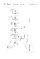
- FIG. 2is a block diagram of a single conversion superheterodyne receiver according to an embodiment of the present invention
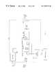
- FIG. 3is a block diagram that illustrates the tuner of FIG. 2, according to an embodiment of the present invention, in greater detail;
- FIG. 4is a block diagram illustrating the tuner of FIG. 3, according to an embodiment of the present invention, in more detail.
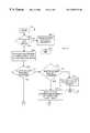
- FIGS. 5A-Bare flowcharts illustrating a technique for reducing adjacent channel interference, according to an embodiment of the present invention.
- a majority of commercial FM receiversare single conversion superheterodyne receivers. These receivers are capable of tuning across the FM broadcast band (approximately 88 to 108 MHz). In these FM receivers, the intermediate frequency (IF) has traditionally been 10.7 MHz with an allocated bandwidth of 200 kHz for each station. Today, many commercial FM receivers are capable of performing alternate frequency (AF) switching under processor control.
- IFintermediate frequency
- an AF switchhas traditionally been utilized when the quality of a desired signal is deficient.
- the channel to switch tois determined by examining radio data system (RDS) information, which is normally transmitted by each broadcasting station.
- RDSradio data system
- a broadcasting station's transmissiontypically includes RDS information about sister stations.
- a sister stationis one which is simultaneously broadcasting the same information, e.g., national public radio (NPR).
- NPRnational public radio
- the present inventionis particularly advantageous when used in conjunction with a receiver that is capable of monitoring signal conditions (e.g., ultrasonic noise) and switching to an adjacent channel.
- the receivermust be capable of shifting to an adjacent channel, determining the signal strength of the adjacent channel and returning to the desired channel all in a time that is imperceptible to a listener.
- a processor controlled receiver implementing the present inventionmust typically accomplish this in about 7 mS or less.
- the present inventionis implemented in a receiver system which has the ability to determine the level of an adjacent channel signal in such a time frame. Additionally, the receiver system can determine the level of a desired signal as well as noise levels (e.g., USN) of the desired signal.
- High noise levels (e.g., USN) on the desired channelindicate interference.
- a programmed processorperforms an AF switch to check signal levels of adjacent channels. When one of the adjacent channels is at a level (with respect to the desired channel) that indicates interference with the desired channel, the receiver is tuned away from the interfering channel. If the noise level on the desired channel improves, the receiver is left in its current state. If the noise level did not improve, the receiver is returned to its original setting.
- FIG. 1shows a simplified block diagram of a single conversion superheterodyne receiver 100 according to the prior art.
- Antenna 102receives radio frequency (RF) signals and supplies those signals to a RF amplifier 104 .
- RF amplifier 104provides pre-amplification for the received signal and couples those signals to an FM mixer 106 .
- FM mixer 106receives a local oscillator signal from a local oscillator 114 . By varying the frequency of the local oscillator signal, the receiver can be tuned across the FM broadcast band.
- the FM mixer 106beats the received signal with the local oscillator signal and provides the mixed signal to IF amplifier 108 .
- IF amplifier 108which includes an IF filter at its input, amplifies the mixed signal and provides an amplified mixed signal to the detector 110 .
- Detector 110may include an automatic gain control (AGC) circuit which is coupled to IF amplifier 108 and provides a gain signal to control the gain of IF amplifier 108 .
- AGCautomatic gain control
- Detector 110detects the audio signal and provides the audio signal to an audio frequency (AF) amplifier 112 .
- the audio frequency amplifieramplifies the audio signal and provides an amplified audio signal to a speaker 116 .
- FIG. 2depicts a single conversion superheterodyne receiver 200 according to an embodiment of the present invention. While only a single conversion receiver is discussed herein, the techniques according to the present invention are equally applicable to other receivers, e.g., double conversion, triple conversion, etc.
- Antenna 202couples a received signal to an RF amplifier 204 .
- RF amplifier 204amplifies the received signal and provides the signal to a FM mixer 206 .
- FM mixer 206beats the received signal with an oscillator signal provided by tuner 214 and provides a mixed signal.
- the frequency of the oscillator signalis adjusted responsive to an I 2 C signal provided by a processor 216 .
- the term processormay include a general purpose processor, a microcontroller (i.e., an execution unit with memory, etc., integrated within a single integrated circuit) or a digital signal processor.
- varying the frequency of the oscillator signalallows the receiver to be tuned across the FM broadcast band.
- FM mixer 206then provides the mixed signal to a first FM IF amplifier 208 A which amplifies the mixed signal.
- FM IF amplifier 208 Aincludes an IF filter at its input.
- FM IF amplifier 208 Ais coupled to a second IF amplifier 208 B.
- FM IF amplifier 208 Balso includes an IF filter at its input.
- FM IF amplifier 208 Bamplifies the mixed signal and provides the mixed signal to a FM detector 210 .
- FM detector 210receives the amplified mixed signal and detects the audio signal.
- the audio signalis provided to an audio frequency (AF) amplifier 212 .
- the audio frequency amplifier 212amplifies the audio signal and provides it to a speaker (not shown).
- FIG. 3further illustrates tuner 214 of FIG. 2 .
- Tuner system 312includes programmable frequency divider 304 , phase detector 306 , charge pump 308 and programmable divider 310 .
- Programmable frequency divider 310receives input from oscillator 318 .
- Programmable frequency divider 304 and programmable divider 310are programmed by a processor 216 across an I 2 C bus.
- a beat signal that is ultimately coupled to FM mixer 206is dependent upon the value programmed into programmable registers (not shown in FIG. 3) of programmable divider 310 and programmable frequency divider 304 .
- Programmable frequency divider 304receives an oscillator signal from crystal oscillator 302 .
- the oscillator signalis divided, as appropriate, and is applied to the phase detector 306 .
- Phase detector 306also receives an input signal from programmable divider 310 .
- Phase detector 306provides an output signal to charge pump 308 .
- Charge pump 308is coupled to a loop filter 314 .
- Loop filter 314is coupled to a tuning network 316 .
- Loop filter 314helps to establish the proper transient response and filtering for transient and steady-state operation.
- Tuning network 316is coupled to a voltage controlled oscillator (VCO) 318 .
- VCO 318produces an output signal whose frequency deviation about a center frequency is proportional to its input voltage.
- VCO 318is coupled to programmable divider 310 .
- Programmable divider 310divides the output of the VCO 318 and provides it to phase detector 306 .
- the output of VCO 318is also provided to a divider 320 .
- the output (mixing signal) of divider 320is coupled to FM mixer 206 .
- tuning system 312the receiver can be tuned across the FM broadcast band at the direction of processor 216 . This programmable feature of many commercial receivers can be advantageously used to minimize the impact of adjacent channel interference.
- FIG. 4illustrates tuning system 312 in more detail.
- Processor 216addresses and controls tuning system 312 utilizing an I 2 C bus.
- Processor 216is coupled to a main control block 404 .
- Main control block 404receives commands from processor 216 and sets appropriate registers ( 304 A and 310 A) of program frequency divider 304 and program divider 310 as directed.
- Programmable divider 310can be implemented as a pulse swallow type counter. Utilizing a programmable frequency divider 304 allows for the use of a number of different crystals.
- Buffer 408buffers the output of crystal 406 into programmable frequency divider 304 .
- programmable frequency divider 304could include a buffer and be directly coupled to crystal 406 .
- the output of VCO 318is coupled to the input of programmable divider 310 .
- Phase detector 306generally includes both a phase and a frequency detector. As previously disclosed, phase detector 306 receives inputs from both programmable frequency divider 304 and programmable divider 310 , and in response to the inputs provides an output to charge pump 308 . In a typical application, the output of charge pump 308 is provided to a loop filter 314 as previously discussed in conjunction with FIG. 3 .
- FIGS. 5A-Billustrate an adjacent channel interference reduction routine 500 , according to an embodiment of the invention.
- controltransfers to step 502 .
- a desired signal level of tenrefers to the value of a digital word.
- the value of the digital wordis determined by reading the voltage level of the desired signal with an A/D converter (internal to processor 216 ). Alternatively, the A/D converter can be external to processor 216 . The voltage reading is then converted to a digital word with a value from zero to sixty-three.
- the internal A/D converteris a 6-bit A/D converter with a resolution of 47 mV.
- a USN level of fiverefers to the value of a digital word.
- a detected audio signal, of the desired channelis coupled through a 70 kHz high pass filter.
- the USN level, of the desired channelis then determined by taking a voltage reading of the filtered audio signal using a 3-bit A/D converter.
- the voltage readingis then converted to a digital word with a value from zero to seven.
- the resolution the 3-bit A/D converteris 340 mV.
- a particular levelrefers to the value of a digital word.
- step 502if the level of the desired signal is not greater than ten or the USN level is not greater than five, control transfers to step 504 .
- routine 500causes the receive to remain tuned to the current frequency. From step 504 , control passes to step 536 where the routine 500 returns to the calling program.
- routine 500performs an alternate frequency (AF) switch to check the signal levels of the upper and lower adjacent channels. If the level of the lower adjacent channel is greater than the desired channel level plus five, control transfers to step 516 . If the level of the lower adjacent channel is less than the desired channel level plus five, control transfers to step 510 . In step 510 , if the level of the upper adjacent channel signal is greater than the desired channel level plus five, control transfers to step 514 . If the level of higher adjacent channel signal is less than five plus the desired channel level, control transfers to step 512 . In step 512 , routine 500 then directs that the VCO not change frequency (because there is no adjacent channel that is presently interfering). From step 512 , control then transfers to step 536 where routine 500 is exited.
- AFalternate frequency
- step 514since the upper adjacent channel signal is interfering with the desired channel signal the VCO is detuned. This is accomplished by programming programmable divider 310 to a lower frequency (changing the divide by N#). This, in essence, detunes the VCO away from the interfering channel. In the preferred embodiment, the VCO is detuned in about 50 kHz increments (station is tuned by about 25 kHz). From step 514 , control then transfers to step 530 .
- routine 500next determines whether the USN level is equal to or better than the standard tuning level. If the USN is less than it previously was, control transfers to step 534 . In step 534 , routine 500 then directs the VCO to remain tuned to the current frequency. From step 534 , routine 500 then proceeds to step 536 . When the USN noise level has increased, in step 530 , control transfers from step 530 to step 532 . In step 532 , routine 500 causes the receiver to return to its original frequency. From step 532 , control passes to step 536 where routine 500 is exited.
- step 508when the level of the lower adjacent channel is greater than the level of the desired channel plus five, control transfers to step 516 .
- routine 500determines whether the level of the upper adjacent channel is greater than five plus the level of the desired channel. If so, control transfers to step 520 . If not, control transfers from step 516 to step 518 .
- routine 500causes the VCO to be detuned toward the upper adjacent channel. From step 518 , control transfers to step 530 . As previously discussed, in conjunction with step 530 , routine 500 determines whether the USN level is equal to or better than it previously had been.
- step 530If detuning the VCO toward the upper adjacent channel has decreased the USN level, control passes from step 530 to step 534 . Otherwise, control transfers from step 530 to step 532 . Step 534 directs the VCO to remain at the current frequency. Step 532 causes the VCO to return to its original frequency. From step 532 or step 534 , control transfers to step 536 and routine 500 is exited.
- step 516if the level of the upper adjacent channel is greater than the desired channel level plus five, control transfers to step 520 .
- routine 500then compares signal magnitudes of the upper adjacent and lower adjacent channels. If the signal level of the channels does not vary by more than a value of five, then control transfers from step 520 to step 522 .
- routine 500directs the VCO to remain in its current state. From step 522 , control transfers to step 536 where routine 500 is exited. From step 520 , if the upper and lower adjacent channel signal levels differ in signal strength by more than five, control transfers to step 524 .
- routine 500determines whether the upper adjacent channel signal strength is less than the lower adjacent channel signal strength. If the upper adjacent channel signal strength is less than the lower adjacent channel signal strength, control transfers to step 528 . If the upper adjacent channel signal strength is greater than or equal to the lower adjacent channel strength, control transfers to step 526 . In step 526 , the VCO is detuned toward the lower adjacent channel. From step 526 , control then transfers to step 530 . In step 528 , routine 500 directs that the VCO be adjusted toward the upper adjacent channel. From step 528 , control then transfers to step 530 .
- a receivercan typically improve the signal-to-noise and distortion (SINAD) level on the desired channel.
- SINADsignal-to-noise and distortion
- the above-described receiveris especially advantageous in mobile applications, e.g., a receiver in an automobile. In the automotive environment, a receiver may frequently change geographic listening areas. In this situation, having a processor controlled receiver that can optimize listening conditions is desireable.
Landscapes
- Engineering & Computer Science (AREA)
- Computer Networks & Wireless Communication (AREA)
- Signal Processing (AREA)
- Noise Elimination (AREA)
Abstract
Description
Claims (20)
Priority Applications (1)
| Application Number | Priority Date | Filing Date | Title |
|---|---|---|---|
| US09/379,231US6389273B1 (en) | 1999-08-23 | 1999-08-23 | Adjacent channel interference reduction in a FM receiver |
Applications Claiming Priority (1)
| Application Number | Priority Date | Filing Date | Title |
|---|---|---|---|
| US09/379,231US6389273B1 (en) | 1999-08-23 | 1999-08-23 | Adjacent channel interference reduction in a FM receiver |
Publications (1)
| Publication Number | Publication Date |
|---|---|
| US6389273B1true US6389273B1 (en) | 2002-05-14 |
Family
ID=23496373
Family Applications (1)
| Application Number | Title | Priority Date | Filing Date |
|---|---|---|---|
| US09/379,231Expired - LifetimeUS6389273B1 (en) | 1999-08-23 | 1999-08-23 | Adjacent channel interference reduction in a FM receiver |
Country Status (1)
| Country | Link |
|---|---|
| US (1) | US6389273B1 (en) |
Cited By (26)
| Publication number | Priority date | Publication date | Assignee | Title |
|---|---|---|---|---|
| US20020155846A1 (en)* | 2001-04-24 | 2002-10-24 | Matsushita Electric Industrial Co., Ltd. | Wireless communication system |
| US6597908B1 (en)* | 2000-02-09 | 2003-07-22 | Lucent Technologies Inc. | Method and system for monitoring traffic carrier performance in a mobile communication system |
| US6781967B1 (en) | 2000-08-29 | 2004-08-24 | Rockwell Collins, Inc. | Scheduling techniques for receiver directed broadcast applications |
| US6791994B1 (en)* | 2000-04-19 | 2004-09-14 | Rockwell Collins, Inc. | Method and apparatus for assigning receive slots in a dynamic assignment environment |
| US6810022B1 (en) | 2000-08-29 | 2004-10-26 | Rockwell Collins | Full duplex communication slot assignment |
| US6885651B1 (en)* | 2000-08-29 | 2005-04-26 | Rockwell Collins | Maintaining an adaptive broadcast channel using both transmitter directed and receiver directed broadcasts |
| US20060189311A1 (en)* | 2005-02-18 | 2006-08-24 | Cromer Daryl C | Apparatus, system, and method for rapid wireless network association |
| US7142624B2 (en)* | 2001-01-16 | 2006-11-28 | International Business Machines Corporation | Analog unidirectional serial link architecture |
| US20060270370A1 (en)* | 2005-05-31 | 2006-11-30 | Michael Bergman | Radio receiver and reserved band filter |
| US20060293010A1 (en)* | 2005-06-28 | 2006-12-28 | Seiko Epson Corporation | Composition purpose signal generating apparatus, IC chip, GPS receiver, and cellular phone |
| US20070254611A1 (en)* | 2006-04-27 | 2007-11-01 | Microsoft Corporation | Radio frequency signal for determining location |
| US7310380B1 (en) | 2004-05-28 | 2007-12-18 | Rockwell Collins, Inc. | Generic transmission parameter configuration |
| US7382799B1 (en) | 2004-05-18 | 2008-06-03 | Rockwell Collins, Inc. | On-demand broadcast protocol |
| US7397810B1 (en) | 2004-06-14 | 2008-07-08 | Rockwell Collins, Inc. | Artery nodes |
| US7403780B2 (en) | 2004-02-19 | 2008-07-22 | Rockwell Collins, Inc. | Hybrid open/closed loop filtering for link quality estimation |
| US20090061801A1 (en)* | 2007-09-04 | 2009-03-05 | Sanyo Electric Co., Ltd. | FM Tuner |
| US7606171B1 (en) | 2005-07-28 | 2009-10-20 | Rockwell Collins, Inc. | Skeletal node rules for connected dominating set in ad-hoc networks |
| US20100130152A1 (en)* | 2008-11-26 | 2010-05-27 | Whikehart J William | Automatic bandwidth control with high-deviation detection |
| US7826372B1 (en) | 2004-03-26 | 2010-11-02 | Rockwell Collins, Inc. | Network routing process for regulating traffic through advantaged and disadvantaged nodes |
| US20100285765A1 (en)* | 2009-05-11 | 2010-11-11 | Olaf Axtmann | Signal analysis for an improved detection of noise from an adjacent channel |
| US20110019830A1 (en)* | 2008-04-01 | 2011-01-27 | Audiodent Israel Ltd. | Antenna Arrangement for a Hearing Instrument |
| US7881688B1 (en)* | 2006-09-29 | 2011-02-01 | Marvell International Ltd. | Method and apparatus for controlling a local oscillator |
| US20110230157A1 (en)* | 2008-11-27 | 2011-09-22 | Huawei Technologies Co., Ltd. | Equivalent radio frequency notch filter, radio frequency chip, and receiver |
| US20120212675A1 (en)* | 2011-02-22 | 2012-08-23 | Shukla Parveen K | Apparatus, systems and methods utilizing adjacent-channel power dependent automatic gain control for digital television demodulation |
| US10862519B1 (en)* | 2020-04-22 | 2020-12-08 | Nxp B.V. | Bandwidth control in radio frequency broadcast signals relative to adjacent-channel signal properties |
| EP3873045A1 (en)* | 2020-02-28 | 2021-09-01 | Nxp B.V. | Fm spectrum estimation relative to adjacent channel |
Citations (31)
| Publication number | Priority date | Publication date | Assignee | Title |
|---|---|---|---|---|
| US3934202A (en)* | 1974-03-25 | 1976-01-20 | Telesonic Systems, Inc. | Tour guide system including means for noise and crosstalk suppression |
| US4267605A (en)* | 1979-02-26 | 1981-05-12 | Trio Kabushiki Kaisha | Interference eliminator in communication receiver |
| US4435618A (en)* | 1981-01-28 | 1984-03-06 | Nippon Gakki Seizo Kabushiki Kaisha | Adjacent station interference rejecting circuit |
| US4723303A (en)* | 1985-04-15 | 1988-02-02 | U.S. Philips Corporation | Method of and circuit arrangement for measuring the quality of radio-transmission channels of a radio-transmission system |
| US4739518A (en)* | 1986-05-22 | 1988-04-19 | Motorola, Inc. | Receiver interference suppression system |
| US4810960A (en)* | 1986-06-14 | 1989-03-07 | Marconi Instruments Ltd. | Measuring adjacent channel power |
| US4907293A (en)* | 1988-08-24 | 1990-03-06 | Pioneer Electronic Corporation | Adjacent channel interference suppressing system for FM receiver |
| US4965849A (en)* | 1988-09-29 | 1990-10-23 | Sony Corporation | Cordless telephone |
| US5109529A (en)* | 1987-09-16 | 1992-04-28 | Nec Corporation | Method of assigning frequency channel in mobile communications system |
| US5148548A (en)* | 1989-12-19 | 1992-09-15 | Northern Telecom Limited | Method of monitoring cellular radio channels to avoid adjacent and co-channel interference |
| US5303414A (en)* | 1990-09-11 | 1994-04-12 | Stefan Brinkhaus | Method and device for minimizing interference, in particular in connection with FM reception |
| US5307515A (en)* | 1991-08-05 | 1994-04-26 | Ford Motor Company | Adjacent channel controller for radio receiver |
| US5369470A (en)* | 1988-05-30 | 1994-11-29 | H.U.C. Elektronik Gmbh | FM receiver which detects and responds to receiving and interference states |
| US5410737A (en)* | 1992-04-27 | 1995-04-25 | American Pcs L.P. | Frequency agile sharing technology (FAST) for a personal communications service system |
| US5428818A (en)* | 1991-11-10 | 1995-06-27 | Motorola Inc. | Method and apparatus for reducing interference in a radio communication link of a cellular communication system |
| US5493717A (en)* | 1993-06-11 | 1996-02-20 | Blaupunkt-Werke Gmbh | Adjacent channel interference detection & suppression circuit |
| US5594946A (en)* | 1995-02-28 | 1997-01-14 | Motorola, Inc. | Method and apparatus for mitigating interference produced by a communication unit in a communication system |
| US5630218A (en)* | 1993-07-21 | 1997-05-13 | Nec Corporation | Radio receiving device for measuring an electric field level of a receiving channel and adjacent channels using common components |
| US5649303A (en)* | 1994-09-02 | 1997-07-15 | Motorola, Inc. | Method and apparatus for reducing interference among communication systems |
| US5697056A (en)* | 1995-05-08 | 1997-12-09 | Motorola, Inc. | Communication system in which radio subscriber units mitigate interference |
| US5737359A (en)* | 1993-09-14 | 1998-04-07 | Nokia Telecommunications Oy | Method for supervising base station radio channels |
| US5808463A (en)* | 1995-11-15 | 1998-09-15 | Advantest Corporation | Method and apparatus for measuring adjacent channel power using complex fourier transform |
| US5924023A (en)* | 1995-12-21 | 1999-07-13 | Anthony J. Smith | Channel operation monitoring in cellular communications networks |
| US6023625A (en)* | 1997-02-18 | 2000-02-08 | Ericsson Inc. | System and method for reducing multicast interference in a distributed antenna network |
| US6035000A (en)* | 1996-04-19 | 2000-03-07 | Amati Communications Corporation | Mitigating radio frequency interference in multi-carrier transmission systems |
| US6047171A (en)* | 1998-01-08 | 2000-04-04 | Ericsson Inc. | Method and apparatus for combating adjacent channel interference using multiple IF filters |
| US6181924B1 (en)* | 1997-07-01 | 2001-01-30 | Telefonaktiebolaget Lm Ericsson (Publ) | Method and system for rejecting interfering signals |
| US6195554B1 (en)* | 1999-02-16 | 2001-02-27 | Ericsson Inc. | Channel assignment based on uplink interference level and channel quality measurements with a forward and backward reassignment step |
| US6212363B1 (en)* | 1989-11-29 | 2001-04-03 | Motorola, Inc. | Method and apparatus for signalling interference protection in a channel reuse radio network |
| US6256477B1 (en)* | 1998-09-30 | 2001-07-03 | Conexant Systems, Inc. | Avoiding interference from a potentially interfering transmitter in a wireless communication system |
| US6301475B1 (en)* | 1996-08-14 | 2001-10-09 | Nokia Networks Oy | Procedure for limiting the mobility area of a terminal device in a wireless local loop |
- 1999
- 1999-08-23USUS09/379,231patent/US6389273B1/ennot_activeExpired - Lifetime
Patent Citations (32)
| Publication number | Priority date | Publication date | Assignee | Title |
|---|---|---|---|---|
| US3934202A (en)* | 1974-03-25 | 1976-01-20 | Telesonic Systems, Inc. | Tour guide system including means for noise and crosstalk suppression |
| US4267605A (en)* | 1979-02-26 | 1981-05-12 | Trio Kabushiki Kaisha | Interference eliminator in communication receiver |
| US4435618A (en)* | 1981-01-28 | 1984-03-06 | Nippon Gakki Seizo Kabushiki Kaisha | Adjacent station interference rejecting circuit |
| US4723303A (en)* | 1985-04-15 | 1988-02-02 | U.S. Philips Corporation | Method of and circuit arrangement for measuring the quality of radio-transmission channels of a radio-transmission system |
| US4739518A (en)* | 1986-05-22 | 1988-04-19 | Motorola, Inc. | Receiver interference suppression system |
| US4810960A (en)* | 1986-06-14 | 1989-03-07 | Marconi Instruments Ltd. | Measuring adjacent channel power |
| US5109529A (en)* | 1987-09-16 | 1992-04-28 | Nec Corporation | Method of assigning frequency channel in mobile communications system |
| US5369470A (en)* | 1988-05-30 | 1994-11-29 | H.U.C. Elektronik Gmbh | FM receiver which detects and responds to receiving and interference states |
| US4907293A (en)* | 1988-08-24 | 1990-03-06 | Pioneer Electronic Corporation | Adjacent channel interference suppressing system for FM receiver |
| US4965849A (en)* | 1988-09-29 | 1990-10-23 | Sony Corporation | Cordless telephone |
| US6212363B1 (en)* | 1989-11-29 | 2001-04-03 | Motorola, Inc. | Method and apparatus for signalling interference protection in a channel reuse radio network |
| US5148548A (en)* | 1989-12-19 | 1992-09-15 | Northern Telecom Limited | Method of monitoring cellular radio channels to avoid adjacent and co-channel interference |
| US5303414A (en)* | 1990-09-11 | 1994-04-12 | Stefan Brinkhaus | Method and device for minimizing interference, in particular in connection with FM reception |
| US5307515A (en)* | 1991-08-05 | 1994-04-26 | Ford Motor Company | Adjacent channel controller for radio receiver |
| US5428818A (en)* | 1991-11-10 | 1995-06-27 | Motorola Inc. | Method and apparatus for reducing interference in a radio communication link of a cellular communication system |
| US5809401A (en)* | 1991-11-10 | 1998-09-15 | Motorola, Inc. | Method and apparatus for reducing interference in a radio communication link of a cellular communication system |
| US5410737A (en)* | 1992-04-27 | 1995-04-25 | American Pcs L.P. | Frequency agile sharing technology (FAST) for a personal communications service system |
| US5493717A (en)* | 1993-06-11 | 1996-02-20 | Blaupunkt-Werke Gmbh | Adjacent channel interference detection & suppression circuit |
| US5630218A (en)* | 1993-07-21 | 1997-05-13 | Nec Corporation | Radio receiving device for measuring an electric field level of a receiving channel and adjacent channels using common components |
| US5737359A (en)* | 1993-09-14 | 1998-04-07 | Nokia Telecommunications Oy | Method for supervising base station radio channels |
| US5649303A (en)* | 1994-09-02 | 1997-07-15 | Motorola, Inc. | Method and apparatus for reducing interference among communication systems |
| US5594946A (en)* | 1995-02-28 | 1997-01-14 | Motorola, Inc. | Method and apparatus for mitigating interference produced by a communication unit in a communication system |
| US5697056A (en)* | 1995-05-08 | 1997-12-09 | Motorola, Inc. | Communication system in which radio subscriber units mitigate interference |
| US5808463A (en)* | 1995-11-15 | 1998-09-15 | Advantest Corporation | Method and apparatus for measuring adjacent channel power using complex fourier transform |
| US5924023A (en)* | 1995-12-21 | 1999-07-13 | Anthony J. Smith | Channel operation monitoring in cellular communications networks |
| US6035000A (en)* | 1996-04-19 | 2000-03-07 | Amati Communications Corporation | Mitigating radio frequency interference in multi-carrier transmission systems |
| US6301475B1 (en)* | 1996-08-14 | 2001-10-09 | Nokia Networks Oy | Procedure for limiting the mobility area of a terminal device in a wireless local loop |
| US6023625A (en)* | 1997-02-18 | 2000-02-08 | Ericsson Inc. | System and method for reducing multicast interference in a distributed antenna network |
| US6181924B1 (en)* | 1997-07-01 | 2001-01-30 | Telefonaktiebolaget Lm Ericsson (Publ) | Method and system for rejecting interfering signals |
| US6047171A (en)* | 1998-01-08 | 2000-04-04 | Ericsson Inc. | Method and apparatus for combating adjacent channel interference using multiple IF filters |
| US6256477B1 (en)* | 1998-09-30 | 2001-07-03 | Conexant Systems, Inc. | Avoiding interference from a potentially interfering transmitter in a wireless communication system |
| US6195554B1 (en)* | 1999-02-16 | 2001-02-27 | Ericsson Inc. | Channel assignment based on uplink interference level and channel quality measurements with a forward and backward reassignment step |
Cited By (41)
| Publication number | Priority date | Publication date | Assignee | Title |
|---|---|---|---|---|
| US6597908B1 (en)* | 2000-02-09 | 2003-07-22 | Lucent Technologies Inc. | Method and system for monitoring traffic carrier performance in a mobile communication system |
| US6791994B1 (en)* | 2000-04-19 | 2004-09-14 | Rockwell Collins, Inc. | Method and apparatus for assigning receive slots in a dynamic assignment environment |
| US6781967B1 (en) | 2000-08-29 | 2004-08-24 | Rockwell Collins, Inc. | Scheduling techniques for receiver directed broadcast applications |
| US6810022B1 (en) | 2000-08-29 | 2004-10-26 | Rockwell Collins | Full duplex communication slot assignment |
| US6885651B1 (en)* | 2000-08-29 | 2005-04-26 | Rockwell Collins | Maintaining an adaptive broadcast channel using both transmitter directed and receiver directed broadcasts |
| US7142624B2 (en)* | 2001-01-16 | 2006-11-28 | International Business Machines Corporation | Analog unidirectional serial link architecture |
| US20040196807A1 (en)* | 2001-04-24 | 2004-10-07 | Matsushita Electric Industrial Co., Ltd. | Wireless communication system |
| US6804523B2 (en)* | 2001-04-24 | 2004-10-12 | Matsushita Electric Industrial Co., Ltd. | Wireless communication system |
| US20040209627A1 (en)* | 2001-04-24 | 2004-10-21 | Matsushita Electric Industrial Co., Ltd. | Wireless communication system |
| US7006830B2 (en)* | 2001-04-24 | 2006-02-28 | Matsushita Electric Industrial Co., Ltd. | Wireless communication system |
| US7062275B2 (en)* | 2001-04-24 | 2006-06-13 | Matsushita Electric Industrial Co., Ltd. | Wireless communication system |
| US20020155846A1 (en)* | 2001-04-24 | 2002-10-24 | Matsushita Electric Industrial Co., Ltd. | Wireless communication system |
| US7403780B2 (en) | 2004-02-19 | 2008-07-22 | Rockwell Collins, Inc. | Hybrid open/closed loop filtering for link quality estimation |
| US7826372B1 (en) | 2004-03-26 | 2010-11-02 | Rockwell Collins, Inc. | Network routing process for regulating traffic through advantaged and disadvantaged nodes |
| US7382799B1 (en) | 2004-05-18 | 2008-06-03 | Rockwell Collins, Inc. | On-demand broadcast protocol |
| US7310380B1 (en) | 2004-05-28 | 2007-12-18 | Rockwell Collins, Inc. | Generic transmission parameter configuration |
| US7397810B1 (en) | 2004-06-14 | 2008-07-08 | Rockwell Collins, Inc. | Artery nodes |
| US7630713B2 (en)* | 2005-02-18 | 2009-12-08 | Lenovo (Singapore) Pte Ltd. | Apparatus, system, and method for rapid wireless network association |
| US20060189311A1 (en)* | 2005-02-18 | 2006-08-24 | Cromer Daryl C | Apparatus, system, and method for rapid wireless network association |
| US20060270370A1 (en)* | 2005-05-31 | 2006-11-30 | Michael Bergman | Radio receiver and reserved band filter |
| US20060293010A1 (en)* | 2005-06-28 | 2006-12-28 | Seiko Epson Corporation | Composition purpose signal generating apparatus, IC chip, GPS receiver, and cellular phone |
| EP1739846A3 (en)* | 2005-06-28 | 2007-10-03 | Seiko Epson Corporation | Signal generating apparatus, IC chip, GPS receiver, and cellular phone |
| US7606171B1 (en) | 2005-07-28 | 2009-10-20 | Rockwell Collins, Inc. | Skeletal node rules for connected dominating set in ad-hoc networks |
| US7844237B2 (en)* | 2006-04-27 | 2010-11-30 | Microsoft Corporation | Radio frequency signal for determining location |
| US20070254611A1 (en)* | 2006-04-27 | 2007-11-01 | Microsoft Corporation | Radio frequency signal for determining location |
| US7881688B1 (en)* | 2006-09-29 | 2011-02-01 | Marvell International Ltd. | Method and apparatus for controlling a local oscillator |
| US20090061801A1 (en)* | 2007-09-04 | 2009-03-05 | Sanyo Electric Co., Ltd. | FM Tuner |
| US8135370B2 (en)* | 2007-09-04 | 2012-03-13 | Sanyo Electric Co., Ltd. | FM tuner having adaptive bandpass filter for adjacent channel interference |
| CN101999236A (en)* | 2008-04-01 | 2011-03-30 | 奥迪欧登特以色列有限公司 | Antenna arrangement for a hearing instrument |
| US20110019830A1 (en)* | 2008-04-01 | 2011-01-27 | Audiodent Israel Ltd. | Antenna Arrangement for a Hearing Instrument |
| US8116713B2 (en)* | 2008-11-26 | 2012-02-14 | Visteon Global Technologies, Inc. | Automatic bandwidth control with high-deviation detection |
| US20100130152A1 (en)* | 2008-11-26 | 2010-05-27 | Whikehart J William | Automatic bandwidth control with high-deviation detection |
| US20110230157A1 (en)* | 2008-11-27 | 2011-09-22 | Huawei Technologies Co., Ltd. | Equivalent radio frequency notch filter, radio frequency chip, and receiver |
| US8385873B2 (en)* | 2008-11-27 | 2013-02-26 | Huawei Technologies Co., Ltd. | Equivalent radio frequency notch filter, radio frequency chip, and receiver |
| US20100285765A1 (en)* | 2009-05-11 | 2010-11-11 | Olaf Axtmann | Signal analysis for an improved detection of noise from an adjacent channel |
| US8270928B2 (en)* | 2009-05-11 | 2012-09-18 | Harman Becker Automotive Systems Gmbh | Signal analysis for an improved detection of noise from an adjacent channel |
| US20120212675A1 (en)* | 2011-02-22 | 2012-08-23 | Shukla Parveen K | Apparatus, systems and methods utilizing adjacent-channel power dependent automatic gain control for digital television demodulation |
| US8582035B2 (en)* | 2011-02-22 | 2013-11-12 | Intel Corporation | Apparatus, systems and methods utilizing adjacent-channel power dependent automatic gain control for digital television demodulation |
| US8817195B2 (en)* | 2011-02-22 | 2014-08-26 | Intel Corporation | Apparatus, systems and methods utilizing adjacent-channel power dependent automatic gain control for digital television demodulation |
| EP3873045A1 (en)* | 2020-02-28 | 2021-09-01 | Nxp B.V. | Fm spectrum estimation relative to adjacent channel |
| US10862519B1 (en)* | 2020-04-22 | 2020-12-08 | Nxp B.V. | Bandwidth control in radio frequency broadcast signals relative to adjacent-channel signal properties |
Similar Documents
| Publication | Publication Date | Title |
|---|---|---|
| US6389273B1 (en) | Adjacent channel interference reduction in a FM receiver | |
| US4352208A (en) | Automatic IF selectivity for radio receiver system | |
| US8260233B2 (en) | FM receiver | |
| WO1998037629A1 (en) | Receiver if system with active filters | |
| JPH06509691A (en) | Adjacent channel controller for radio receivers | |
| US6389272B1 (en) | Receiver with auto gain control circuit of RF signal | |
| US5722060A (en) | Radio receiver | |
| US6480709B2 (en) | Method for reducing scan time in a radio receiver | |
| US6314144B1 (en) | Digital wireless receiving apparatus | |
| JP2542955B2 (en) | Signal strength peak detection circuit in automatic tuning circuit | |
| US7308235B2 (en) | Audio broadcast receiver and automatic broadcasting-station selecting method | |
| US20050215212A1 (en) | Receiver | |
| JP2003518861A (en) | Image removal | |
| JPH0389720A (en) | Radio receiver | |
| JPH03145339A (en) | Am radio receiver | |
| JPS6318177Y2 (en) | ||
| JPH0254705B2 (en) | ||
| JP3994330B2 (en) | Radio receiver and radio reception tuning method | |
| JPH0317254B2 (en) | ||
| EP0132307A2 (en) | Receiver having a noise blanker | |
| JPH03158016A (en) | Am radio receiver | |
| JPH04247723A (en) | Detector for radio communication wave | |
| JPS6041331A (en) | radio receiver | |
| KR20010012983A (en) | AM quality detector | |
| JPS6218982Y2 (en) |
Legal Events
| Date | Code | Title | Description |
|---|---|---|---|
| AS | Assignment | Owner name:DELPHI TECHNOLOGIES, INC., MICHIGAN Free format text:ASSIGNMENT OF ASSIGNORS INTEREST;ASSIGNOR:BRANDENBURG, TODD MATTHEW;REEL/FRAME:010771/0345 Effective date:20000404 | |
| STCF | Information on status: patent grant | Free format text:PATENTED CASE | |
| AS | Assignment | Owner name:JPMORGAN CHASE BANK, N.A., TEXAS Free format text:SECURITY AGREEMENT;ASSIGNOR:DELPHI TECHNOLOGIES, INC.;REEL/FRAME:016237/0402 Effective date:20050614 | |
| AS | Assignment | Owner name:DELPHI TECHNOLOGIES INC., MICHIGAN Free format text:ASSIGNMENT OF ASSIGNORS INTEREST;ASSIGNOR:DELCO ELECTRONICS CORPORATION;REEL/FRAME:017115/0208 Effective date:20050930 | |
| REMI | Maintenance fee reminder mailed | ||
| FPAY | Fee payment | Year of fee payment:4 | |
| SULP | Surcharge for late payment | ||
| AS | Assignment | Owner name:DELPHI TECHNOLOGIES, INC., MICHIGAN Free format text:RELEASE OF SECURITY AGREEMENT;ASSIGNOR:JPMORGAN CHASE BANK, N.A.;REEL/FRAME:020808/0583 Effective date:20080225 | |
| FPAY | Fee payment | Year of fee payment:8 | |
| AS | Assignment | Owner name:TAB TWO LIMITED LIABILITY COMPANY, DELAWARE Free format text:ASSIGNMENT OF ASSIGNORS INTEREST;ASSIGNOR:DELPHI TECHNOLOGIES, INC.;REEL/FRAME:027768/0202 Effective date:20120203 | |
| FPAY | Fee payment | Year of fee payment:12 | |
| AS | Assignment | Owner name:GULA CONSULTING LIMITED LIABILITY COMPANY, WASHING Free format text:MERGER;ASSIGNOR:TAB TWO LIMITED LIABILITY COMPANY;REEL/FRAME:036669/0336 Effective date:20150828 |