US6388575B1 - Addressable underground marker - Google Patents
Addressable underground markerDownload PDFInfo
- Publication number
- US6388575B1 US6388575B1US09/704,846US70484600AUS6388575B1US 6388575 B1US6388575 B1US 6388575B1US 70484600 AUS70484600 AUS 70484600AUS 6388575 B1US6388575 B1US 6388575B1
- Authority
- US
- United States
- Prior art keywords
- tuned circuit
- marker
- transponder
- tuned
- buried
- Prior art date
- Legal status (The legal status is an assumption and is not a legal conclusion. Google has not performed a legal analysis and makes no representation as to the accuracy of the status listed.)
- Expired - Lifetime
Links
- 239000003550markerSubstances0.000titleclaimsabstractdescription76
- 238000004146energy storageMethods0.000claimsabstractdescription14
- 238000000034methodMethods0.000claimsabstractdescription11
- 230000004044responseEffects0.000claimsdescription7
- 230000010363phase shiftEffects0.000claimsdescription6
- XLYOFNOQVPJJNP-UHFFFAOYSA-NwaterSubstancesOXLYOFNOQVPJJNP-UHFFFAOYSA-N0.000description5
- 239000003990capacitorSubstances0.000description4
- 238000010586diagramMethods0.000description4
- 230000000007visual effectEffects0.000description3
- 230000001960triggered effectEffects0.000description2
- 238000009412basement excavationMethods0.000description1
- 238000009933burialMethods0.000description1
- 230000002596correlated effectEffects0.000description1
- 239000000284extractSubstances0.000description1
- 239000006260foamSubstances0.000description1
- 238000004519manufacturing processMethods0.000description1
- 238000013507mappingMethods0.000description1
- 239000003973paintSubstances0.000description1
- 230000035939shockEffects0.000description1
Images


Classifications
- G—PHYSICS
- G01—MEASURING; TESTING
- G01V—GEOPHYSICS; GRAVITATIONAL MEASUREMENTS; DETECTING MASSES OR OBJECTS; TAGS
- G01V15/00—Tags attached to, or associated with, an object, in order to enable detection of the object
Definitions
- the present inventionrelates to electrical markers that are located underground for the purpose of locating buried structures.
- Buried structuresinclude pipelines, cables, etc. Once a structure is buried in the ground, it becomes difficult to locate. Location is useful, for example, to dig up the structure for repair or to avoid the structure when performing nearby excavation.
- Electrical markersare used to locate buried structures. The markers are located adjacent to a structure and then are buried with that structure.
- each markercontains one or more tuned LC circuits.
- Each circuittypically includes a coil of wire.
- an operatormoves across the surface of the ground with a transmitter and a receiver.
- the transmittersends out an electromagnetic signal tuned to the frequency of the marker.
- the markerUpon receiving the transmitted signal, the marker resonates and thus produces an electromagnetic response.
- This responseis received by the above ground receiver and converted to a signal that is detectable by the operator (for example, an audio tone).
- the operatormarks the pinpointed location on the ground using paint and then moves on to find the next marker buried along the structure.
- the location of the marker and the location of the buried structurecan be determined.
- each utilityhas a particular frequency of marker.
- a marker intended for use by a water utilityis made to operate at a first frequency
- a marker intended for use by a telephone utilityis made to operate at a second frequency.
- a telephone utility buried structurefor example, a cable
- a water utility buried structurefor example, a water pipe
- Buried structurescan be nonuniform and have substructures that are of interest.
- a buried telephone cablecan have a splice. Locating the splice with prior art markers is difficult. This is because it is difficult to identify a particular one of the many markers that may be buried along the length of the cable. Each marker is virtually indistinguishable from the other marker except by its location.
- an underground markerthat can be distinguished from all of the other underground markers that lie along the same buried structures. Such a marker would allow the location of particular substructures, such as a splice, a vault hatch, a valve, etc.
- the present inventionprovides an apparatus for use in locating buried structures.
- the apparatushas a tuned circuit having an inductance and a capacitance.
- An energy storage deviceis connected to the tuned circuit.
- a transponderhas a power input that is connected to the energy storage device and a trigger input connected to the tuned circuit.
- the transponderhas a memory for containing and identifying code.
- the transponderhas an output that is connected to the tuned circuit. The transponder operates to transmit by way of the tuned circuit the identifying code when the trigger input is activated.
- the inductoris a flat circular coil.
- the transpondercomprises a shift register.
- the apparatusfurther comprises a phase shift transmitter coupled to the transponder output and to the tuned circuit.
- the apparatusfurther comprises a waterproof housing surrounding the tuned circuit, the energy storage device and the transponder.
- the tuned circuitis a first tuned circuit.
- the apparatusfurther comprises a second tuned circuit with a second transponder electrically coupled thereto.
- the first and second tuned circuitsare nonplanar with respect to each other.
- the apparatusfurther comprises a third tuned circuit with a third transponder electrically coupled thereto.
- the first, second and third tuned circuitsare nonplanar with respect to each other.
- the inventionprovides a method of identifying a buried structure.
- a tuned circuit having an impedanceis provided.
- the tuned circuitis tuned to a selected frequency.
- Electromagnetic energy at the selected frequencyis received by way of the tuned circuit, wherein the tuned circuit resonates.
- the resonating in the tuned circuitis interrupted in accordance with a coded pattern.
- the step of interrupting the resonating of the tuned circuit in accordance with a coded patternfurther comprises the step of changing the impedence of the tuned circuit in accordance with the coded pattern.
- the methodfurther comprises the step of burying the tuned circuit adjacent to the buried structure before the step of receiving electromagnetic energy.
- a buried first markeris provided adjacent to the structure.
- the markerhas an identifying code and a transponder.
- a second markeris buried some distance away from the structure.
- the groundis subjected to electromagnetic energy at a selected frequency.
- a second responseis obtained from the second marker so as to locate the second marker.
- the groundis subjected to the electromagnetic energy, searching from the location of the second marker for the first marker. Then, the identifying code in the first response is detected so as to locate the first marker.
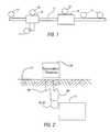
- FIG. 1is a schematic plan view of a buried structure with markers of the present invention adjacent thereto.
- FIG. 2is a schematic elevational view of a cross-section of earth, showing the use of the present invention.
- FIG. 3is a block diagram of a transmitter and receiver that is used to locate a marker.
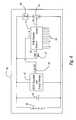
- FIG. 4is a block diagram of the marker.
- FIG. 5is a plan cross-sectional view of the marker.
- FIG. 6is an isometric view of the marker, in accordance with a preferred embodiment.
- FIG. 1there is shown a diagram of a buried structure 11 .
- the buried structure 11 showncould be a cable, a pipeline, etc.
- the buried structure 11has substructures 13 , 15 which are of interest.
- substructures 13 , 15which are of interest.
- enclosures 13there are enclosures 13 , splices 15 , etc.
- valves 15there are T-fittings 13 , valves 15 , etc.
- Markers 17 , 19 , 21are buried with the structure 11 .
- the markersare located adjacent to the structure. Some of the markers 17 are conventional and may be such as are disclosed in my U.S. Pat. No. 5,699,048. These markers resonate at a selected frequency and provide information on the location of the buried structure.
- the other markers 19 , 21 located adjacent to the substructures 13 , 15are addressable in that they provide a unique identification code.
- the marker 19 that is buried next to the substructure 13will provide a first identification code (for example, binary 10010011) when prompted.
- the marker 21 that is buried next to the substructure 15will provide a second identification code (for example, binary 11100010) when prompted.
- a unique identification codean operator can identify a particular marker 19 , 21 among the many buried markers 17 , 19 , 21 and can thus pinpoint the location of the substructure relative to the remainder of the buried structure.
- a telephone cable splice 15may be identified in telephone company records as number 8321 located at the intersection of Throckmorton and Fifth Streets (or in the alternative as being located at specific Global Positioning System coordinates or other mapping coordinates).
- a marker 21 having a unique identification codeis located adjacent to the splice 15 . The specific location of the splice can be determined when that marker is found by an operator who utilizes surface equipment.
- markerscan be used to “home” in on the particular marker of interest and thus to the particular substructure of interest.
- the operatorcan locate a marker 17 . Once located, the operator can continue along the length of the cable using the other markers 17 along the way until reaching the marker 19 or 21 of interest.
- the Global Positioning SystemGPS
- the approximate location of the markerif the GPS coordinates are known, wherein the exact location of the marker can then be determined using the techniques discussed herein.
- FIG. 2shows in general the operation of the marker system.
- the marker 19 , 21is first buried adjacent to the structure 11 . After burial, the marker can be located by surface equipment 23 .
- the surface equipment 23 utilized by an operatorcontains a transmitter and a receiver (or a transceiver) and is located above the ground or the earth 27 .
- the transmitterproduces a signal 25 at the frequency of interest. This signal penetrates the earth 27 and impinges on the marker 19 .
- the marker 19has an antenna that receives the signal. Inside of the marker is a transponder that transmits the unique identification signal 29 back to the surface equipment.
- the surface equipment 23receives the signal 29 and processes it to extract the identification code that is associated with that marker. Identifying information about the marker 19 is then provided to the operator in visual, audible, or other forms.
- the identifying codecan be unique to a single marker.
- the identifying codecan be unique to a group of markers, such as for those markers that are to be used adjacent to valves.
- FIG. 3there is shown a schematic block diagram of the surface transmitter and receiver 23 .
- the transmitter portionhas a signal generator 31 .
- the output of the generatoris connected to an amplifier 33 , which in turn is connected to an antenna 35 , such as a coil.
- the signal generator 31produces a signal (such as a sine wave) at the frequency of interest. If desired, the transmitter can produce plural signals, each at a selected frequency.
- the receiver portionis connected to an antenna 35 A (or to the antenna 35 ) and has a filter 37 connected thereto.
- the filter 37can be a bandpass filter that excludes noise above and below the frequency band of interest.
- the output of the filter 37is connected to a decoder or demodulator 39 .
- the decoder 39which has memory, extracts the coded information from the marker signal 29 .
- the signalmay have header information or other information, which is decoded using information in the memory.
- the output of the decoderis connected to an indicator 41 .
- the indicatorprovides an audible or visual indication of the marker's identity.
- the coded informationcan be converted into a base 10 (ten) number, which is then provided to the operator. The number can then be correlated to the particular buried structure that is marked by the marker.
- One or more bits of the coded informationcan be used to identify characteristics of the buried structure. For example, a segment of the code can be used to identify the buried structure as a valve or a splice, or as a water utility structure.
- FIG. 4illustrates the transponder electronics located inside of a marker 19 , 21 .
- FIG. 4is exemplary, as other types of transponders can be used.
- a transponderis described in U.S. Pat. No. 5,211,129, the disclosure of which is incorporated herein by reference.
- the markerhas an antenna 43 in the form of a coil.
- a capacitor 45is connected in parallel with the coil 43 to make an LC circuit 43 , 45 that is tuned to the frequency of the generator 31 .
- Connected in parallel with the tuned LC circuitis an ac/dc regulator and energy storage device 47 .
- the device 47can be a relatively large capacitor that can be used to store energy received by the LC circuit.
- the device 47has a diode that rectifies and regulates the energy.
- the output 49 of the regulator and energy storage device 47is a dc voltage.
- a rotating type of shift register 51is provided.
- the regulator and energy storage device 47powers the shift register 51 .
- the shift register 51has programmable inputs 53 , which allow a string of data bits (D N ) to be programmed therein. The inputs can be programmed, for example, by being open or grounded.
- the shift registerhas a clock, or trigger, input 55 that is connected to the LC circuit 43 , 45 .
- a voltage limiter 57can be provided in series with the input 55 if needed.
- the output 59 of the shift register 51is connected to a switch 61 .
- the switch 61 and an impedance 63(such as a small capacitor) are connected across the LC circuit 43 , 45 .
- switch 61When the switch 61 is closed, continuity is provided and the impedance is connected across the LC circuit. When the switch 61 is open, continuity is broken and the impedance is no longer connected across the LC circuit.
- the switch 61is operable between its open and closed positions by the output 59 of the shift register 51 .
- the electronicsare contained within a waterproof housing 65 .
- the LC circuit 43 , 45receives the signal and resonates.
- the regulator and energy storage device 47captures some of the resonant energy in order to power the shift register 51 .
- the shift register 51can operate the switch 61 according to the coded format as represented by its stored data bits.
- the clock input 55is triggered and one bit is provided to the output 59 .
- the output 59operates the switch depending on the value of the bit.
- the received signal provided to the clock inputgoes low because of the ac nature of the signal.
- the clock input 55is triggered and the next bit in the shift register is provided to the output.
- the data bits and the shift registerare thus provided in a sequential manner to operate the switch 61 .
- the switch 61is operated in accordance with the value of the bit on the output 59 of the shift register. For example, if the bit is a “1”, then the switch is closed; if the bit is a “0”, the switch is opened.
- the switch 61When the switch 61 is closed, the impedance 63 is connected across the LC circuit 43 , 45 .
- the signal 29(see FIG. 2) produced by the resonating LC circuit shifts in phase due to the added impedance. If the switch 61 is open, the impedance is disconnected from the LC circuit and there is no phase shift or change in the signal 29 .
- the code as represented by the bit sequence stored in the shift registeris transmitted by the LC circuit as phase shifts.
- the decoder 39 in the surface equipment 23detects these phase shifts in the signal 29 .
- the beginning of the coded informationcan be represented by a header.
- the headeris a bit sequence that is common to each addressable marker.
- the shift register 51being of the rotary type, can thus transmit the coded information a number of times until the energy provided by the regulator and energy storage device 47 becomes insufficient to operate the shift register 51 .
- the coded informationneed not be transmitted with the header bits as the initial bits.
- the surface receiverutilizes the header to identify the beginning of the coded information.
- the shift registercan output its string of bits once and then reset, so that the same bit is always transmitted first.
- the codeis programmed into the shift register during manufacture and before the housing 65 is sealed.
- the codecan be imprinted onto the housing 65 for visual reference. This allows an installer to notate in a database which marker is installed where.
- the transpondercan have separate transmit and receive antennas/coils. Also, various types of encoding and modulation can be used by the transponder.
- FIG. 5shows a marker 19 , 21 in accordance with a preferred embodiment.
- the coil 43is relatively large, on the order of 2-4 inches. The coil of course can be smaller or larger, depending on the particular need.
- the electronics 69which includes the capacitor 45 and the remaining components 47 , 51 , etc. as shown in FIG. 4, are located inside of the coil 43 and are electrically coupled to the coil as required. In order to minimize shock damage, the electronics 69 can be taped or otherwise secured to the coil 43 . In addition, foam can fill the interior space of the coil.
- the coil 43 and the electronics 69are put into the waterproof housing 65 .
- FIG. 6illustrates another embodiment of the marker 71 (the housing is not shown in FIG. 6 ).
- the markerhas three orthogonal tuned circuits 73 , as discussed in U.S. Pat. No. 5,699,048. This orthogonal arrangement provides an omnidirectional response, which is particularly desired in buried markers.
- Each tuned circuithas electronics 69 coupled thereto.
- each tuned circuithas a transponder.
- the transponders in a single markercan all be programmed with the same coded information. Alternatively, the transponders in a single marker can have unique codes. Such a marker is useful in determining if the orientation in the marker and the surrounding structure has changed over time.
Landscapes
- Physics & Mathematics (AREA)
- Life Sciences & Earth Sciences (AREA)
- General Life Sciences & Earth Sciences (AREA)
- General Physics & Mathematics (AREA)
- Geophysics (AREA)
- Geophysics And Detection Of Objects (AREA)
- Radar Systems Or Details Thereof (AREA)
Abstract
Description
Claims (12)
Priority Applications (1)
| Application Number | Priority Date | Filing Date | Title |
|---|---|---|---|
| US09/704,846US6388575B1 (en) | 1999-11-05 | 2000-11-02 | Addressable underground marker |
Applications Claiming Priority (2)
| Application Number | Priority Date | Filing Date | Title |
|---|---|---|---|
| US16392599P | 1999-11-05 | 1999-11-05 | |
| US09/704,846US6388575B1 (en) | 1999-11-05 | 2000-11-02 | Addressable underground marker |
Publications (1)
| Publication Number | Publication Date |
|---|---|
| US6388575B1true US6388575B1 (en) | 2002-05-14 |
Family
ID=26860090
Family Applications (1)
| Application Number | Title | Priority Date | Filing Date |
|---|---|---|---|
| US09/704,846Expired - LifetimeUS6388575B1 (en) | 1999-11-05 | 2000-11-02 | Addressable underground marker |
Country Status (1)
| Country | Link |
|---|---|
| US (1) | US6388575B1 (en) |
Cited By (29)
| Publication number | Priority date | Publication date | Assignee | Title |
|---|---|---|---|---|
| US6690278B2 (en)* | 2001-12-28 | 2004-02-10 | Gas Technology Institute | Electronic marker for metallic valve box covers |
| US6777829B2 (en)* | 2002-03-13 | 2004-08-17 | Celis Semiconductor Corporation | Rectifier utilizing a grounded antenna |
| US20040178795A1 (en)* | 2003-03-12 | 2004-09-16 | Tempo Research Corporation | Method of and system for locating a single passive underground electronic marker type that distinguishes false indication caused by other marker types |
| US20040183680A1 (en)* | 2003-03-12 | 2004-09-23 | Tempo Research Corporation | Method of and system for rapidly locating all passive underground electronic marker types |
| DE10315845A1 (en)* | 2003-04-08 | 2004-11-04 | Richter, Wolfgang | Selective switching signal generation for vehicle locking systems, involves capacitively coupling signal into user, transmitting signal through user and user generating switching signal on basis of coupled in signal |
| GB2408418A (en)* | 2003-11-20 | 2005-05-25 | David Milnes | Buried transponder for identification of highway excavations/reinstatements |
| US20050121526A1 (en)* | 2003-12-09 | 2005-06-09 | Intelleflex Corporation | Battery activation circuit |
| US20050156600A1 (en)* | 2002-10-09 | 2005-07-21 | Olsson Mark S. | Single and multi-trace omnidirectional sonde and line locators and transmitter used therewith |
| US20060068754A1 (en)* | 2004-09-30 | 2006-03-30 | Helena Goldfarb | System and method for securing a large infrastructure |
| US7091872B1 (en)* | 2002-07-01 | 2006-08-15 | Metrotech Corporation | Controlled power source for underground line location |
| US20060255131A1 (en)* | 2005-05-11 | 2006-11-16 | Intelleflex Corporation | Smart tag activation |
| US20070018794A1 (en)* | 2005-07-20 | 2007-01-25 | Intelleflex Corporation | Selective RF device activation |
| US20070141983A1 (en)* | 2005-12-15 | 2007-06-21 | Intelleflex Corporation | Clock-free activation circuit |
| US20080252449A1 (en)* | 2007-04-13 | 2008-10-16 | Claiton Pereira Colvero | Device, system and method for the location and identification of as-built plants of pipes, conduits, cables or hidden objects |
| GB2449650A (en)* | 2007-05-30 | 2008-12-03 | Ritag | RFID marker |
| US20090121965A1 (en)* | 2007-11-13 | 2009-05-14 | Atmel Corporation | Spherical antenna |
| US20100147583A1 (en)* | 2007-05-15 | 2010-06-17 | Lapp Engineering & Co. | Cable |
| US20100165557A1 (en)* | 2007-07-19 | 2010-07-01 | Lapp Engineering & Co. | Cable receiving unit |
| US20100166374A1 (en)* | 2007-04-10 | 2010-07-01 | Lapp Engineering & Co. | Cable |
| US20100172618A1 (en)* | 2007-04-10 | 2010-07-08 | Lapp Engineering & Co. | Cable |
| US7755360B1 (en) | 2005-10-24 | 2010-07-13 | Seektech, Inc. | Portable locator system with jamming reduction |
| US7830149B1 (en) | 2002-10-09 | 2010-11-09 | Seektech, Inc. | Underground utility locator with a transmitter, a pair of upwardly opening pockets and helical coil type electrical cords |
| US20110215808A1 (en)* | 2010-03-05 | 2011-09-08 | Sameer Cholayil | Passive underground electronic marker for use in any orientation |
| US8368518B1 (en)* | 2012-04-04 | 2013-02-05 | National Metering Services, Inc. | Access-integrated RFID-based asset management system |
| US8515230B2 (en) | 2007-04-10 | 2013-08-20 | Lapp Engineering & Co. | Cable with embedded information carrier unit |
| US20140125457A1 (en)* | 2012-11-05 | 2014-05-08 | Berntsen International, Inc. | Underground Asset Management System |
| WO2015058012A1 (en)* | 2013-10-17 | 2015-04-23 | Seescan, Inc | Electronic marker devices and systems |
| US11280934B2 (en) | 2018-06-21 | 2022-03-22 | SeeScan, Inc. | Electromagnetic marker devices for buried or hidden use |
| US11467317B2 (en)* | 2019-06-20 | 2022-10-11 | SeeScan, Inc. | Electromagnetic marker devices with separate receive and transmit antenna elements |
Citations (64)
| Publication number | Priority date | Publication date | Assignee | Title |
|---|---|---|---|---|
| US3373498A (en) | 1965-06-11 | 1968-03-19 | Henri Jules Chabbert | Magnetic compass |
| US3683389A (en) | 1971-01-20 | 1972-08-08 | Corning Glass Works | Omnidirectional loop antenna array |
| US3689885A (en) | 1970-09-15 | 1972-09-05 | Transitag Corp | Inductively coupled passive responder and interrogator unit having multidimension electromagnetic field capabilities |
| US3719950A (en) | 1971-11-03 | 1973-03-06 | A Bukhman | Antenna system for vhf and uhf radio direction finders |
| US3818487A (en) | 1972-08-24 | 1974-06-18 | W Brody | Soft control materials |
| US3836842A (en) | 1973-01-22 | 1974-09-17 | Bell Canada Northern Electric | Encapsulated electrically resonant circuit and interrogating apparatus and method for finding same in various locations |
| US3938044A (en) | 1973-11-14 | 1976-02-10 | Lichtblau G J | Antenna apparatus for an electronic security system |
| US3983552A (en) | 1975-01-14 | 1976-09-28 | American District Telegraph Company | Pilferage detection systems |
| US4118693A (en) | 1977-05-09 | 1978-10-03 | Knogo Corporation | Method and apparatus for producing uniform electromagnetic fields in an article detection system |
| US4119908A (en)* | 1975-11-28 | 1978-10-10 | A. P. C. Industries, Inc. | Method for locating buried markers which are disposed along the path of an underground conductor |
| US4240072A (en) | 1979-03-19 | 1980-12-16 | Research Products Corporation | Load indicator for an air cleaner |
| US4260983A (en) | 1978-01-11 | 1981-04-07 | Tag Radionics Limited | Presence sensing detector and system for detecting a receiver/transmitter device affixed to an article |
| US4292590A (en) | 1979-11-13 | 1981-09-29 | Westinghouse Electric Corp. | Magnetometer apparatus with detector immobilized in wax |
| US4293816A (en) | 1979-07-09 | 1981-10-06 | White's Electronics, Inc. | Balanced search loop for metal detector |
| US4334227A (en) | 1980-09-26 | 1982-06-08 | A.P.C. Industries, Inc. | Electronic marker device and method of making same |
| US4342904A (en) | 1980-10-27 | 1982-08-03 | Minnesota Mining And Manufacturing Company | Lightweight ferromagnetic marker for the detection of objects having markers secured thereto |
| US4482513A (en) | 1981-03-10 | 1984-11-13 | General Dynamics, Pomona Division | Method of molding foam/aluminum flake microwave lenses |
| US4581524A (en) | 1983-04-26 | 1986-04-08 | Minnesota Mining And Manufacturing Company | Flexible ferromagnetic marker for the detection of objects having markers secured thereto |
| US4668912A (en) | 1985-02-05 | 1987-05-26 | Westinghouse Electric Corp. | Eddy current inspection probe and method for assembling same |
| US4712094A (en) | 1986-05-29 | 1987-12-08 | Minnesota Mining And Manufacturing Company | Self-orienting passive marker structure |
| US4761656A (en) | 1986-05-23 | 1988-08-02 | Minnesota Mining And Manufacturing Company | Passive marker device |
| US4767237A (en)* | 1986-08-26 | 1988-08-30 | Minnesota Mining And Manufacturing Company | Marking tape with wire conductors and methods for use |
| US4798175A (en) | 1986-10-09 | 1989-01-17 | Alfa-Laval Agri, Inc. | Electronic identification system |
| US4859991A (en) | 1987-08-28 | 1989-08-22 | Sensormatic Electronics Corporation | Electronic article surveillance system employing time domain and/or frequency domain analysis and computerized operation |
| US4866388A (en) | 1988-05-11 | 1989-09-12 | Minnesota Mining And Manufacturing Company | System and method with passive resonant circuit markers for locating buried electrical conductors |
| US4864749A (en) | 1988-04-05 | 1989-09-12 | Brown David C | Tag for identifying survey traverse points |
| US4873530A (en) | 1985-09-30 | 1989-10-10 | Nissan Motor Co., Ltd. | Antenna device in automotive keyless entry system |
| US4873533A (en)* | 1986-11-18 | 1989-10-10 | Minnesota Mining And Manufacturing Company | Marker for locating a buried object |
| US4894663A (en) | 1987-11-16 | 1990-01-16 | Motorola, Inc. | Ultra thin radio housing with integral antenna |
| US4925605A (en) | 1986-10-02 | 1990-05-15 | Field Foam Incorporated | Method of forming a heat foam insulation jacket |
| US5017415A (en) | 1989-09-18 | 1991-05-21 | Minnesota Mining And Manufacturing Company | Self-dispensing spaced electronic markers |
| US5028918A (en) | 1989-12-18 | 1991-07-02 | Dairy Equipment Company | Identification transponder circuit |
| US5045368A (en)* | 1989-09-18 | 1991-09-03 | Minnesota Mining And Manufacturing Company | Self-dispensing spaced electronic markers |
| US5047715A (en) | 1987-12-22 | 1991-09-10 | Morgenstern Juergen | Electromagnetic device for position measurement having multiple coils with equal area of turn cross-section |
| US5057844A (en) | 1990-03-19 | 1991-10-15 | Rothstein Mark B | Insulated underground antenna and method for utilizing same |
| US5103234A (en) | 1987-08-28 | 1992-04-07 | Sensormatic Electronics Corporation | Electronic article surveillance system |
| US5116654A (en) | 1989-09-18 | 1992-05-26 | Minnesota Mining And Manufacturing Company | Self-dispensing spaced electronic markers |
| US5121103A (en) | 1988-07-29 | 1992-06-09 | Knogo Corporation | Load isolated article surveillance system and antenna assembly |
| US5140334A (en) | 1991-01-07 | 1992-08-18 | Gte Government Systems Corp. | Compact omnidirectional antenna |
| US5211129A (en) | 1986-02-25 | 1993-05-18 | Destron/Idi, Inc. | Syringe-implantable identification transponder |
| US5258766A (en) | 1987-12-10 | 1993-11-02 | Uniscan Ltd. | Antenna structure for providing a uniform field |
| US5270717A (en) | 1992-03-26 | 1993-12-14 | Texas Instruments Deutschland Gmbh | Extended range RF-ID transponder |
| US5276067A (en) | 1991-09-20 | 1994-01-04 | Miles Inc. | HCFC blown rigid foams with low thermal conductivity |
| US5280296A (en) | 1992-04-29 | 1994-01-18 | Motorola, Inc. | Antenna system for a wrist carried selective call receiver |
| US5281941A (en) | 1991-08-14 | 1994-01-25 | Elliot Bernstein | Coil form and coil for antenna coils, or the like |
| US5326095A (en)* | 1988-03-21 | 1994-07-05 | Yardmark, Inc. | Golf information system |
| US5397986A (en) | 1991-11-01 | 1995-03-14 | Federal Labs Systems Lp | Metal detector system having multiple, adjustable transmitter and receiver antennas |
| US5426443A (en) | 1994-01-18 | 1995-06-20 | Jenness, Jr.; James R. | Dielectric-supported reflector system |
| US5497099A (en) | 1991-09-06 | 1996-03-05 | Engine Control Systems Ltd. | Antenna system for soot detecting |
| US5499015A (en) | 1994-09-28 | 1996-03-12 | Sensormatic Electronics Corp. | Magnetomechanical EAS components integrated with a retail product or product packaging |
| US5532598A (en)* | 1994-05-25 | 1996-07-02 | Westinghouse Electric Corporation | Amorphous metal tagging system for underground structures including elongated particles of amorphous metal embedded in nonmagnetic and nonconductive material |
| US5539421A (en) | 1993-07-31 | 1996-07-23 | Daewoo Electronics Co., Ltd. | Planar antenna with helical antenna array and waveguide |
| US5585811A (en) | 1993-06-11 | 1996-12-17 | Actron Enwicklungs Ag | Antenna device for electronic product anti-theft systems |
| US5592182A (en) | 1995-07-10 | 1997-01-07 | Texas Instruments Incorporated | Efficient, dual-polarization, three-dimensionally omni-directional crossed-loop antenna with a planar base element |
| US5699048A (en) | 1996-10-03 | 1997-12-16 | Industrial Technology Inc. | Omnidirectional passive electrical marker for underground use |
| US5814986A (en) | 1997-03-18 | 1998-09-29 | Eaton Corporation | Coil retainer/positioner for inductive proximity sensor |
| US5825298A (en) | 1996-01-16 | 1998-10-20 | Walter; Kenneth E. | Radio frequency transponder method for identifying geographical locations such as survey traverse points |
| US5920194A (en)* | 1994-05-06 | 1999-07-06 | Radiodetection Limited | Device for locating objects that emit electromagnetic signals |
| US5999107A (en) | 1997-11-12 | 1999-12-07 | Institute Of Gas Technology | Remote cathodic protection monitoring system |
| US6049279A (en) | 1999-01-04 | 2000-04-11 | Minarovic; Joe T. | Detectable transponder conduit end cap |
| US6097293A (en) | 1999-04-15 | 2000-08-01 | Industrial Technology, Inc. | Passive electrical marker for underground use and method of making thereof |
| US6097189A (en)* | 1997-09-29 | 2000-08-01 | The United States Of America As Represented By The Administrator Of The National Aeronautics And Space Administration | Object locating system |
| US6133738A (en)* | 1998-10-02 | 2000-10-17 | Minarovic; Joe T. | Detectable transponder reel housing |
| US6271667B1 (en) | 1998-10-02 | 2001-08-07 | Joe T. Minarovic | Buried closure guard with electronic marker |
- 2000
- 2000-11-02USUS09/704,846patent/US6388575B1/ennot_activeExpired - Lifetime
Patent Citations (64)
| Publication number | Priority date | Publication date | Assignee | Title |
|---|---|---|---|---|
| US3373498A (en) | 1965-06-11 | 1968-03-19 | Henri Jules Chabbert | Magnetic compass |
| US3689885A (en) | 1970-09-15 | 1972-09-05 | Transitag Corp | Inductively coupled passive responder and interrogator unit having multidimension electromagnetic field capabilities |
| US3683389A (en) | 1971-01-20 | 1972-08-08 | Corning Glass Works | Omnidirectional loop antenna array |
| US3719950A (en) | 1971-11-03 | 1973-03-06 | A Bukhman | Antenna system for vhf and uhf radio direction finders |
| US3818487A (en) | 1972-08-24 | 1974-06-18 | W Brody | Soft control materials |
| US3836842A (en) | 1973-01-22 | 1974-09-17 | Bell Canada Northern Electric | Encapsulated electrically resonant circuit and interrogating apparatus and method for finding same in various locations |
| US3938044A (en) | 1973-11-14 | 1976-02-10 | Lichtblau G J | Antenna apparatus for an electronic security system |
| US3983552A (en) | 1975-01-14 | 1976-09-28 | American District Telegraph Company | Pilferage detection systems |
| US4119908A (en)* | 1975-11-28 | 1978-10-10 | A. P. C. Industries, Inc. | Method for locating buried markers which are disposed along the path of an underground conductor |
| US4118693A (en) | 1977-05-09 | 1978-10-03 | Knogo Corporation | Method and apparatus for producing uniform electromagnetic fields in an article detection system |
| US4260983A (en) | 1978-01-11 | 1981-04-07 | Tag Radionics Limited | Presence sensing detector and system for detecting a receiver/transmitter device affixed to an article |
| US4240072A (en) | 1979-03-19 | 1980-12-16 | Research Products Corporation | Load indicator for an air cleaner |
| US4293816A (en) | 1979-07-09 | 1981-10-06 | White's Electronics, Inc. | Balanced search loop for metal detector |
| US4292590A (en) | 1979-11-13 | 1981-09-29 | Westinghouse Electric Corp. | Magnetometer apparatus with detector immobilized in wax |
| US4334227A (en) | 1980-09-26 | 1982-06-08 | A.P.C. Industries, Inc. | Electronic marker device and method of making same |
| US4342904A (en) | 1980-10-27 | 1982-08-03 | Minnesota Mining And Manufacturing Company | Lightweight ferromagnetic marker for the detection of objects having markers secured thereto |
| US4482513A (en) | 1981-03-10 | 1984-11-13 | General Dynamics, Pomona Division | Method of molding foam/aluminum flake microwave lenses |
| US4581524A (en) | 1983-04-26 | 1986-04-08 | Minnesota Mining And Manufacturing Company | Flexible ferromagnetic marker for the detection of objects having markers secured thereto |
| US4668912A (en) | 1985-02-05 | 1987-05-26 | Westinghouse Electric Corp. | Eddy current inspection probe and method for assembling same |
| US4873530A (en) | 1985-09-30 | 1989-10-10 | Nissan Motor Co., Ltd. | Antenna device in automotive keyless entry system |
| US5211129A (en) | 1986-02-25 | 1993-05-18 | Destron/Idi, Inc. | Syringe-implantable identification transponder |
| US4761656A (en) | 1986-05-23 | 1988-08-02 | Minnesota Mining And Manufacturing Company | Passive marker device |
| US4712094A (en) | 1986-05-29 | 1987-12-08 | Minnesota Mining And Manufacturing Company | Self-orienting passive marker structure |
| US4767237A (en)* | 1986-08-26 | 1988-08-30 | Minnesota Mining And Manufacturing Company | Marking tape with wire conductors and methods for use |
| US4925605A (en) | 1986-10-02 | 1990-05-15 | Field Foam Incorporated | Method of forming a heat foam insulation jacket |
| US4798175A (en) | 1986-10-09 | 1989-01-17 | Alfa-Laval Agri, Inc. | Electronic identification system |
| US4873533A (en)* | 1986-11-18 | 1989-10-10 | Minnesota Mining And Manufacturing Company | Marker for locating a buried object |
| US4859991A (en) | 1987-08-28 | 1989-08-22 | Sensormatic Electronics Corporation | Electronic article surveillance system employing time domain and/or frequency domain analysis and computerized operation |
| US5103234A (en) | 1987-08-28 | 1992-04-07 | Sensormatic Electronics Corporation | Electronic article surveillance system |
| US4894663A (en) | 1987-11-16 | 1990-01-16 | Motorola, Inc. | Ultra thin radio housing with integral antenna |
| US5258766A (en) | 1987-12-10 | 1993-11-02 | Uniscan Ltd. | Antenna structure for providing a uniform field |
| US5047715A (en) | 1987-12-22 | 1991-09-10 | Morgenstern Juergen | Electromagnetic device for position measurement having multiple coils with equal area of turn cross-section |
| US5326095A (en)* | 1988-03-21 | 1994-07-05 | Yardmark, Inc. | Golf information system |
| US4864749A (en) | 1988-04-05 | 1989-09-12 | Brown David C | Tag for identifying survey traverse points |
| US4866388A (en) | 1988-05-11 | 1989-09-12 | Minnesota Mining And Manufacturing Company | System and method with passive resonant circuit markers for locating buried electrical conductors |
| US5121103A (en) | 1988-07-29 | 1992-06-09 | Knogo Corporation | Load isolated article surveillance system and antenna assembly |
| US5045368A (en)* | 1989-09-18 | 1991-09-03 | Minnesota Mining And Manufacturing Company | Self-dispensing spaced electronic markers |
| US5116654A (en) | 1989-09-18 | 1992-05-26 | Minnesota Mining And Manufacturing Company | Self-dispensing spaced electronic markers |
| US5017415A (en) | 1989-09-18 | 1991-05-21 | Minnesota Mining And Manufacturing Company | Self-dispensing spaced electronic markers |
| US5028918A (en) | 1989-12-18 | 1991-07-02 | Dairy Equipment Company | Identification transponder circuit |
| US5057844A (en) | 1990-03-19 | 1991-10-15 | Rothstein Mark B | Insulated underground antenna and method for utilizing same |
| US5140334A (en) | 1991-01-07 | 1992-08-18 | Gte Government Systems Corp. | Compact omnidirectional antenna |
| US5281941A (en) | 1991-08-14 | 1994-01-25 | Elliot Bernstein | Coil form and coil for antenna coils, or the like |
| US5497099A (en) | 1991-09-06 | 1996-03-05 | Engine Control Systems Ltd. | Antenna system for soot detecting |
| US5276067A (en) | 1991-09-20 | 1994-01-04 | Miles Inc. | HCFC blown rigid foams with low thermal conductivity |
| US5397986A (en) | 1991-11-01 | 1995-03-14 | Federal Labs Systems Lp | Metal detector system having multiple, adjustable transmitter and receiver antennas |
| US5270717A (en) | 1992-03-26 | 1993-12-14 | Texas Instruments Deutschland Gmbh | Extended range RF-ID transponder |
| US5280296A (en) | 1992-04-29 | 1994-01-18 | Motorola, Inc. | Antenna system for a wrist carried selective call receiver |
| US5585811A (en) | 1993-06-11 | 1996-12-17 | Actron Enwicklungs Ag | Antenna device for electronic product anti-theft systems |
| US5539421A (en) | 1993-07-31 | 1996-07-23 | Daewoo Electronics Co., Ltd. | Planar antenna with helical antenna array and waveguide |
| US5426443A (en) | 1994-01-18 | 1995-06-20 | Jenness, Jr.; James R. | Dielectric-supported reflector system |
| US5920194A (en)* | 1994-05-06 | 1999-07-06 | Radiodetection Limited | Device for locating objects that emit electromagnetic signals |
| US5532598A (en)* | 1994-05-25 | 1996-07-02 | Westinghouse Electric Corporation | Amorphous metal tagging system for underground structures including elongated particles of amorphous metal embedded in nonmagnetic and nonconductive material |
| US5499015A (en) | 1994-09-28 | 1996-03-12 | Sensormatic Electronics Corp. | Magnetomechanical EAS components integrated with a retail product or product packaging |
| US5592182A (en) | 1995-07-10 | 1997-01-07 | Texas Instruments Incorporated | Efficient, dual-polarization, three-dimensionally omni-directional crossed-loop antenna with a planar base element |
| US5825298A (en) | 1996-01-16 | 1998-10-20 | Walter; Kenneth E. | Radio frequency transponder method for identifying geographical locations such as survey traverse points |
| US5699048A (en) | 1996-10-03 | 1997-12-16 | Industrial Technology Inc. | Omnidirectional passive electrical marker for underground use |
| US5814986A (en) | 1997-03-18 | 1998-09-29 | Eaton Corporation | Coil retainer/positioner for inductive proximity sensor |
| US6097189A (en)* | 1997-09-29 | 2000-08-01 | The United States Of America As Represented By The Administrator Of The National Aeronautics And Space Administration | Object locating system |
| US5999107A (en) | 1997-11-12 | 1999-12-07 | Institute Of Gas Technology | Remote cathodic protection monitoring system |
| US6133738A (en)* | 1998-10-02 | 2000-10-17 | Minarovic; Joe T. | Detectable transponder reel housing |
| US6271667B1 (en) | 1998-10-02 | 2001-08-07 | Joe T. Minarovic | Buried closure guard with electronic marker |
| US6049279A (en) | 1999-01-04 | 2000-04-11 | Minarovic; Joe T. | Detectable transponder conduit end cap |
| US6097293A (en) | 1999-04-15 | 2000-08-01 | Industrial Technology, Inc. | Passive electrical marker for underground use and method of making thereof |
Non-Patent Citations (2)
| Title |
|---|
| 23 mm Glass Encapsulated Transponder Reference Manual, Texas Instruments Registration and Identification System (TIRIS), Jul. 25, 1996, pp. 1-22. |
| Tag-it Radio Frequency Identification Systems brochure, Texas Instruments, 2000, 13 pages. |
Cited By (52)
| Publication number | Priority date | Publication date | Assignee | Title |
|---|---|---|---|---|
| US6690278B2 (en)* | 2001-12-28 | 2004-02-10 | Gas Technology Institute | Electronic marker for metallic valve box covers |
| US6777829B2 (en)* | 2002-03-13 | 2004-08-17 | Celis Semiconductor Corporation | Rectifier utilizing a grounded antenna |
| US7091872B1 (en)* | 2002-07-01 | 2006-08-15 | Metrotech Corporation | Controlled power source for underground line location |
| US9989662B1 (en) | 2002-10-09 | 2018-06-05 | SeeScan, Inc. | Buried object locating device with a plurality of spherical sensor balls that include a plurality of orthogonal antennae |
| US7830149B1 (en) | 2002-10-09 | 2010-11-09 | Seektech, Inc. | Underground utility locator with a transmitter, a pair of upwardly opening pockets and helical coil type electrical cords |
| US7619516B2 (en) | 2002-10-09 | 2009-11-17 | Seektech, Inc. | Single and multi-trace omnidirectional sonde and line locators and transmitter used therewith |
| US20050156600A1 (en)* | 2002-10-09 | 2005-07-21 | Olsson Mark S. | Single and multi-trace omnidirectional sonde and line locators and transmitter used therewith |
| US9696447B1 (en) | 2002-10-09 | 2017-07-04 | SeeScan, Inc. | Buried object locating methods and apparatus using multiple electromagnetic signals |
| US7170411B2 (en)* | 2003-03-12 | 2007-01-30 | Tempo Research Corporation | Method of and system for rapidly locating all passive underground electronic marker types |
| US20040178795A1 (en)* | 2003-03-12 | 2004-09-16 | Tempo Research Corporation | Method of and system for locating a single passive underground electronic marker type that distinguishes false indication caused by other marker types |
| US20040183680A1 (en)* | 2003-03-12 | 2004-09-23 | Tempo Research Corporation | Method of and system for rapidly locating all passive underground electronic marker types |
| US7095231B2 (en) | 2003-03-12 | 2006-08-22 | Tempo Research Corporation | Method of and system for locating a single passive underground electronic marker type that distinguishes false indication caused by other marker types |
| DE10315845B4 (en)* | 2003-04-08 | 2005-10-06 | Wolfgang Richter | System, system components and method for processing a hermetically validatable data transfer |
| DE10315845A1 (en)* | 2003-04-08 | 2004-11-04 | Richter, Wolfgang | Selective switching signal generation for vehicle locking systems, involves capacitively coupling signal into user, transmitting signal through user and user generating switching signal on basis of coupled in signal |
| GB2408418A (en)* | 2003-11-20 | 2005-05-25 | David Milnes | Buried transponder for identification of highway excavations/reinstatements |
| US7612652B2 (en) | 2003-12-09 | 2009-11-03 | Intelleflex Corporation | Battery activation circuit |
| US20050121526A1 (en)* | 2003-12-09 | 2005-06-09 | Intelleflex Corporation | Battery activation circuit |
| US20060068754A1 (en)* | 2004-09-30 | 2006-03-30 | Helena Goldfarb | System and method for securing a large infrastructure |
| US20060255131A1 (en)* | 2005-05-11 | 2006-11-16 | Intelleflex Corporation | Smart tag activation |
| US7604178B2 (en) | 2005-05-11 | 2009-10-20 | Intelleflex Corporation | Smart tag activation |
| US20070018794A1 (en)* | 2005-07-20 | 2007-01-25 | Intelleflex Corporation | Selective RF device activation |
| US8674809B2 (en) | 2005-07-20 | 2014-03-18 | Intelleflex Corporation | Selective RF device activation |
| US8248211B2 (en) | 2005-07-20 | 2012-08-21 | Intelleflex Corporation | Selective RF device activation |
| US7755360B1 (en) | 2005-10-24 | 2010-07-13 | Seektech, Inc. | Portable locator system with jamming reduction |
| US7990151B2 (en) | 2005-10-24 | 2011-08-02 | Seektech, Inc. | Tri-pod buried locator system |
| US10677820B2 (en) | 2005-10-24 | 2020-06-09 | SeeScan, Inc. | Buried locators systems and methods |
| US20070141983A1 (en)* | 2005-12-15 | 2007-06-21 | Intelleflex Corporation | Clock-free activation circuit |
| US8548098B2 (en) | 2005-12-15 | 2013-10-01 | Intelleflex Corporation | Clock-free activation circuit |
| US8155491B2 (en) | 2007-04-10 | 2012-04-10 | Lapp Engineering & Co. | Cable |
| US20100172618A1 (en)* | 2007-04-10 | 2010-07-08 | Lapp Engineering & Co. | Cable |
| US20100166374A1 (en)* | 2007-04-10 | 2010-07-01 | Lapp Engineering & Co. | Cable |
| US8515230B2 (en) | 2007-04-10 | 2013-08-20 | Lapp Engineering & Co. | Cable with embedded information carrier unit |
| US7969295B2 (en)* | 2007-04-13 | 2011-06-28 | Claiton Pereira Colvero | Device, system and method for the location and identification of as-built plants of pipes, conduits, cables or hidden objects |
| US20080252449A1 (en)* | 2007-04-13 | 2008-10-16 | Claiton Pereira Colvero | Device, system and method for the location and identification of as-built plants of pipes, conduits, cables or hidden objects |
| US8487181B2 (en)* | 2007-05-15 | 2013-07-16 | Lapp Engineering & Co. | Cable with embedded information carrier unit |
| US20100147583A1 (en)* | 2007-05-15 | 2010-06-17 | Lapp Engineering & Co. | Cable |
| GB2449650A (en)* | 2007-05-30 | 2008-12-03 | Ritag | RFID marker |
| US20100165557A1 (en)* | 2007-07-19 | 2010-07-01 | Lapp Engineering & Co. | Cable receiving unit |
| US8629774B2 (en) | 2007-07-19 | 2014-01-14 | Lapp Engineering & Co. | Cable receiving unit |
| US20090121965A1 (en)* | 2007-11-13 | 2009-05-14 | Atmel Corporation | Spherical antenna |
| US20110215808A1 (en)* | 2010-03-05 | 2011-09-08 | Sameer Cholayil | Passive underground electronic marker for use in any orientation |
| US8368518B1 (en)* | 2012-04-04 | 2013-02-05 | National Metering Services, Inc. | Access-integrated RFID-based asset management system |
| US9235823B2 (en)* | 2012-11-05 | 2016-01-12 | Bernsten International, Inc. | Underground asset management system |
| US20140125457A1 (en)* | 2012-11-05 | 2014-05-08 | Berntsen International, Inc. | Underground Asset Management System |
| US9746572B2 (en) | 2013-10-17 | 2017-08-29 | SeeScan, Inc. | Electronic marker devices and systems |
| WO2015058012A1 (en)* | 2013-10-17 | 2015-04-23 | Seescan, Inc | Electronic marker devices and systems |
| US10859727B2 (en) | 2013-10-17 | 2020-12-08 | SeeScan, Inc. | Electronic marker devices and systems |
| US11624851B1 (en) | 2013-10-17 | 2023-04-11 | SeeScan, Inc. | Electronic marker devices and systems |
| US11280934B2 (en) | 2018-06-21 | 2022-03-22 | SeeScan, Inc. | Electromagnetic marker devices for buried or hidden use |
| US11686878B1 (en) | 2018-06-21 | 2023-06-27 | Seescan, Inc | Electromagnetic marker devices for buried or hidden use |
| US12210130B1 (en) | 2018-06-21 | 2025-01-28 | SeeScan, Inc. | Electromagnetic marker devices for buried or hidden use |
| US11467317B2 (en)* | 2019-06-20 | 2022-10-11 | SeeScan, Inc. | Electromagnetic marker devices with separate receive and transmit antenna elements |
Similar Documents
| Publication | Publication Date | Title |
|---|---|---|
| US6388575B1 (en) | Addressable underground marker | |
| US11988798B1 (en) | Buried utility marker devices, systems, and methods | |
| US11280934B2 (en) | Electromagnetic marker devices for buried or hidden use | |
| US3836842A (en) | Encapsulated electrically resonant circuit and interrogating apparatus and method for finding same in various locations | |
| US9000778B2 (en) | Communication method for monitoring pipelines | |
| US5017415A (en) | Self-dispensing spaced electronic markers | |
| US4119908A (en) | Method for locating buried markers which are disposed along the path of an underground conductor | |
| US11467317B2 (en) | Electromagnetic marker devices with separate receive and transmit antenna elements | |
| JP4225654B2 (en) | Object embedded position detection method and apparatus | |
| US20110181289A1 (en) | Locator assembly for detecting, locating and identifying buried objects and method of use | |
| US5116654A (en) | Self-dispensing spaced electronic markers | |
| US6271667B1 (en) | Buried closure guard with electronic marker | |
| CN104239921A (en) | Underground pipeline marking and real-time depth measurement system | |
| CN1129985A (en) | Conductor locator adapter for electronic markers | |
| CA2066602A1 (en) | Electronic markers with predetermined spacing | |
| EP1308753A2 (en) | Method and apparatus for resolving the position and identity of buried conductive bodies | |
| CN103793733A (en) | Pipeline identification system based on RFID | |
| US10204298B2 (en) | UHF RFID tag for marking underground assets and locations and method of using same | |
| HU192119B (en) | Signalling apparatus under the earth level | |
| US6133738A (en) | Detectable transponder reel housing | |
| CN1091521C (en) | Location marking system and marker for use in system | |
| KR20050050454A (en) | System and method for detecting material laid under the ground using rfid | |
| JP2887221B2 (en) | Management method of maintenance information of underground buried objects | |
| US6690278B2 (en) | Electronic marker for metallic valve box covers | |
| KR102799206B1 (en) | Underground Utility Managing System With Tag Unit |
Legal Events
| Date | Code | Title | Description |
|---|---|---|---|
| STCF | Information on status: patent grant | Free format text:PATENTED CASE | |
| FEPP | Fee payment procedure | Free format text:PAYOR NUMBER ASSIGNED (ORIGINAL EVENT CODE: ASPN); ENTITY STATUS OF PATENT OWNER: SMALL ENTITY | |
| FPAY | Fee payment | Year of fee payment:4 | |
| AS | Assignment | Owner name:TEMPO RESEARCH CORPORATION, CALIFORNIA Free format text:MERGER;ASSIGNOR:INDUSTRIAL TECHNOLOGY, INC.;REEL/FRAME:021861/0202 Effective date:20021216 Owner name:GREENLEE TEXTRON INC., ILLINOIS Free format text:MERGER;ASSIGNOR:TEMPO RESEARCH CORPORATION;REEL/FRAME:021861/0178 Effective date:20060620 | |
| FPAY | Fee payment | Year of fee payment:8 | |
| FPAY | Fee payment | Year of fee payment:12 | |
| AS | Assignment | Owner name:GREENLEE TOOLS, INC., ILLINOIS Free format text:CHANGE OF NAME;ASSIGNOR:GREENLEE TEXTRON INC.;REEL/FRAME:048288/0860 Effective date:20170110 | |
| AS | Assignment | Owner name:TEMPO COMMUNICATIONS, INC., CALIFORNIA Free format text:ASSIGNMENT OF ASSIGNORS INTEREST;ASSIGNOR:GREENLEE TOOLS, INC.;REEL/FRAME:048263/0400 Effective date:20190131 Owner name:GREENLEE TOOLS, INC., ILLINOIS Free format text:CHANGE OF NAME;ASSIGNOR:GREENLEE TEXTRON INC.;REEL/FRAME:048284/0616 Effective date:20180723 | |
| FEPP | Fee payment procedure | Free format text:ENTITY STATUS SET TO SMALL (ORIGINAL EVENT CODE: SMAL); ENTITY STATUS OF PATENT OWNER: SMALL ENTITY | |
| AS | Assignment | Owner name:AMERICAN BANK OF COMMERCE, TEXAS Free format text:SECURITY INTEREST;ASSIGNOR:TEMPO COMMUNICATIONS, INC.;REEL/FRAME:049893/0500 Effective date:20190129 | |
| AS | Assignment | Owner name:FOCUS STRATEGIES MERCHANT INVESTMENTS, LLC, TEXAS Free format text:SECURITY INTEREST;ASSIGNOR:TEMPO COMMUNICATIONS, INC.;REEL/FRAME:049905/0886 Effective date:20190130 | |
| AS | Assignment | Owner name:FOCUS STRATEGIES CAPITAL ADVISORS, LLC, TEXAS Free format text:ASSIGNMENT OF ASSIGNORS INTEREST;ASSIGNOR:FOCUS STRATEGIES MERCHANT INVESTMENTS, LLC;REEL/FRAME:055150/0647 Effective date:20200831 |