US6388262B1 - Double tilt and rotate specimen holder for a transmission electron microscope - Google Patents
Double tilt and rotate specimen holder for a transmission electron microscopeDownload PDFInfo
- Publication number
- US6388262B1 US6388262B1US09/373,515US37351599AUS6388262B1US 6388262 B1US6388262 B1US 6388262B1US 37351599 AUS37351599 AUS 37351599AUS 6388262 B1US6388262 B1US 6388262B1
- Authority
- US
- United States
- Prior art keywords
- specimen
- holder
- cradle
- specimen holder
- axis
- Prior art date
- Legal status (The legal status is an assumption and is not a legal conclusion. Google has not performed a legal analysis and makes no representation as to the accuracy of the status listed.)
- Expired - Lifetime
Links
- 230000005540biological transmissionEffects0.000titleclaimsdescription16
- 238000010894electron beam technologyMethods0.000claimsabstractdescription10
- 238000004458analytical methodMethods0.000claimsabstractdescription6
- 230000007246mechanismEffects0.000claimsdescription52
- 230000033001locomotionEffects0.000claimsdescription22
- 238000000034methodMethods0.000claimsdescription8
- 230000008878couplingEffects0.000claimsdescription3
- 238000010168coupling processMethods0.000claimsdescription3
- 238000005859coupling reactionMethods0.000claimsdescription3
- 239000002178crystalline materialSubstances0.000claimsdescription3
- 239000000463materialSubstances0.000claimsdescription3
- 239000002244precipitateSubstances0.000claimsdescription2
- 238000004627transmission electron microscopyMethods0.000abstractdescription14
- 230000008901benefitEffects0.000description2
- 238000005516engineering processMethods0.000description2
- 238000003384imaging methodMethods0.000description2
- 241000272165CharadriidaeSpecies0.000description1
- 238000001816coolingMethods0.000description1
- 230000000694effectsEffects0.000description1
- 238000010438heat treatmentMethods0.000description1
- 230000013011matingEffects0.000description1
- 239000002184metalSubstances0.000description1
- 230000000717retained effectEffects0.000description1
- 229920002994synthetic fiberPolymers0.000description1
- 238000003325tomographyMethods0.000description1
- 230000000007visual effectEffects0.000description1
Images


Classifications
- H—ELECTRICITY
- H01—ELECTRIC ELEMENTS
- H01J—ELECTRIC DISCHARGE TUBES OR DISCHARGE LAMPS
- H01J37/00—Discharge tubes with provision for introducing objects or material to be exposed to the discharge, e.g. for the purpose of examination or processing thereof
- H01J37/02—Details
- H01J37/20—Means for supporting or positioning the object or the material; Means for adjusting diaphragms or lenses associated with the support
- H—ELECTRICITY
- H01—ELECTRIC ELEMENTS
- H01J—ELECTRIC DISCHARGE TUBES OR DISCHARGE LAMPS
- H01J2237/00—Discharge tubes exposing object to beam, e.g. for analysis treatment, etching, imaging
- H01J2237/20—Positioning, supporting, modifying or maintaining the physical state of objects being observed or treated
- H01J2237/202—Movement
- H01J2237/20207—Tilt
- H—ELECTRICITY
- H01—ELECTRIC ELEMENTS
- H01J—ELECTRIC DISCHARGE TUBES OR DISCHARGE LAMPS
- H01J2237/00—Discharge tubes exposing object to beam, e.g. for analysis treatment, etching, imaging
- H01J2237/20—Positioning, supporting, modifying or maintaining the physical state of objects being observed or treated
- H01J2237/202—Movement
- H01J2237/20214—Rotation
- H—ELECTRICITY
- H01—ELECTRIC ELEMENTS
- H01J—ELECTRIC DISCHARGE TUBES OR DISCHARGE LAMPS
- H01J2237/00—Discharge tubes exposing object to beam, e.g. for analysis treatment, etching, imaging
- H01J2237/25—Tubes for localised analysis using electron or ion beams
- H01J2237/2505—Tubes for localised analysis using electron or ion beams characterised by their application
- H01J2237/2538—Low energy electron microscopy [LEEM]
- H01J2237/2544—Diffraction [LEED]
Definitions
- the present inventionrelates to specimen holders for transmission electron microscopes, and more particularly to side-entry specimen holders which are tiltable about two axes and rotatable about the electron beam axis.
- TEM specimen holdersused in transmission electron microscopy (TEM) have become more widely used because of their simple and reliable mechanisms; however, as the technology of new materials advances so do requirements for TEM specimen viewing and specimen positioning.
- Conventional side entry TEM specimen holdershave been developed which are capable of only a single axis tilt, which is the simplest type of specimen holder. In this form, the specimen is fixed to the specimen holder tip and has no means of independent motion. Tilting of the specimen in this axis (i.e., the longitudinal axis of the specimen holder) is accomplished by tilting the complete specimen holder about this axis in either direction.
- Double tilt specimen holderscombine the two tilt axes as described above with the second axis tilt in either direction typically accomplished by movement of a drive rod mechanically coupled to a cradle supported by two pivot pins (axles).
- Stereological studies of crystalline materialshave been hindered in that single tilt and rotate holders were limiting in use due to lack of a second axis tilt mechanism. Such stereological studies are complicated by the contrast change that occurs when a specimen is tilted. To minimize this effect, the specimen can first be rotated so that the g vector principally responsible for the contrast is aligned parallel to the tilt axis. The specimen can then be tilted without substantially altering the diffraction-contrast conditions. However, this involves manually changing the position of the specimen while outside of the transmission electron microscope (i.e., requires specimen unloading and re-loading) to attain proper alignment.
- the ability to tilt in two axes and rotate a specimen containing a feature (interface) to align the feature in the direction of various microscope detectorscan facilitate feature analysis in the TEM.
- the use of CCD cameras for TEM digital imagingmakes it desirable to be able to rotate the specimen in a specific direction (visual image alignment) for a given crystallographic condition.
- the present inventionmeets that need by providing a side-entry specimen holder for transmission electron microscopy capable of rotating a specimen and tilting it in two axes.
- the specimenwhen mounted in the holder, can be tilted in the plus/minus direction of the first (longitudinal) axis, the plus/minus direction of the second (normal to longitudinal) axis, and simultaneously have the ability of continuous 360° rotation in the axis of the electron beam to permit alignment while viewing the specimen in the TEM. Further, because of the provision for rotation of the specimen, the viewing axis of the specimen may be aligned to the first or second axis, permitting very high tilt angles.
- a side-entry specimen holder for a transmission electron microscopeincludes a specimen holder having a specimen cradle, a cradle frame, and a drive shaft connected to the specimen cradle and frame; a first tilt mechanism for tilting the specimen holder about a first longitudinal axis; a second tilt mechanism for tilting the specimen cradle about a second axis normal to the first axis; and a rotation mechanism for rotating the specimen cradle.
- tilting in the first axisis accomplished by tilting the entire specimen holder.
- a preferred first tilt mechanismcomprises a drive for rotating the support arm about its longitudinal axis.
- the second tilt mechanismcomprises a drive for moving a drive shaft which is linked through a spherical bearing to a frame housing the specimen cradle.
- the frame for the specimen cradlealso preferably includes a support arm (barrel).
- the rotation mechanismmay be any of a number of mechanisms which are described below and may be endless (full 360°) or limited in rotation.
- a preferred rotation mechanismcomprises a pinion drive gear mating with a ring gear.
- the specimen cradleincludes the ring gear about its periphery, which is engaged and driven by the pinion gear to provide for the rotation of the cradle.
- a method for analyzing one or more physical features of a specimen in a transmission electron microscopeincludes the steps of mounting a specimen to be analyzed in a holder capable of tilting in two axes and rotation, inserting the holder and specimen into the path of an electron beam from the transmission electron microscope, rotating the specimen in the holder to align a physical feature of interest relative to a first tilt axis, and tilting the holder in both of the first and second axes to analyze said physical feature.
- the physical feature of interestmay include microstructural features selected from the group consisting of grain boundaries, precipitates, and interfaces in crystalline materials.
- the methodincludes the step of analyzing the specimen when tilted about the first axis, rotating the specimen in the holder while in the transmission electron microscope to align the physical feature of the specimen to the second axis, tilting the specimen about the second axis, and performing further analysis of the specimen.
- Another aspect of the inventionprovides a method for analyzing one or more physical features of a specimen in a transmission electron microscope and includes the steps of mounting a specimen to be analyzed in a holder capable of tilting in two axes and rotation, inserting the holder and specimen into the path of an electron beam from the transmission electron microscope (TEM), rotating the specimen in the holder to align a physical feature of interest with a TEM detector, and tilting the holder in both of the first and second axes to analyze the physical feature.
- TEMtransmission electron microscope
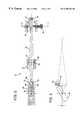
- FIG. 1is a schematic perspective view of the distal end of the specimen holder illustrating the ability of the holder to tilt in two axes (longitudinal and normal to longitudinal) and rotate about the axis of the electron beam (Z-axis);
- FIG. 2is a side view, in section, of one embodiment of the specimen holder
- FIG. 3is a top view, in section, of the distal end of one embodiment of the specimen holder
- FIG. 4is a sectional view taken along line 4 — 4 in FIG. 2;
- FIG. 5is a side view of the specimen holder illustrating the operation of the tilt mechanism about the second axis
- FIG. 6is a top view of the specimen cradle and a preferred gear drive mechanism
- FIG. 7is a side view, in section, of the specimen cradle and the preferred gear drive mechanism of FIG. 6;
- FIG. 8is a top view of the specimen cradle and a friction drive mechanism
- FIG. 9is a side view, in section, of the specimen cradle and the friction drive mechanism of FIG. 8;
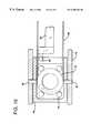
- FIG. 10is a top view of the specimen cradle and a belt drive mechanism
- FIG. 11is a partial side view, in section, of the belt drive mechanism of FIG. 10;
- FIG. 12is a side view, in section, of the specimen cradle and the belt drive mechanism of FIG. 10;
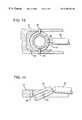
- FIG. 13is a top view of the specimen cradle and a spherical drive mechanism
- FIG. 14is a side view, in section, of the specimen cradle and the spherical drive mechanism of FIG. 13;
- FIG. 15is a top view of the specimen cradle and a ribbon drive mechanism
- FIG. 16is a side view, in section, of another embodiment of the specimen holder.
- the present inventionwill be described in detail with respect to its preferred embodiment which is as a side-entry specimen holder for a transmission electron microscope. It will be apparent that the specimen holder may be adapted to operate in other types of electron and ion microscopes and related instruments. Further, as is conventional in this art, the specimen holder of the present invention may be modified to include either heating or cooling (e.g., cryogenic) capabilities.
- the specimen holderis designed to be inserted into the column of an electron microscope so that the specimen carried thereon may be aligned with an electron beam which traverses the column.
- a distal end or tip of specimen holder 10includes a specimen cradle 12 contained in a frame 48 .
- the specimen 13which has been previously prepared, is mounted in the specimen holder tip 15 secured in cradle 12 .
- the X-, Y-, and Z-axes of movement of the specimen holderare defined as follows.
- the X-axisrefers to the longitudinal axis of specimen holder 10 , with movement toward the distal end or tip of specimen holder 10 being defined as the positive (+) direction and movement in the opposite direction being defined as the minus or negative ( ⁇ ) direction. Tilting of the specimen holder may occur in a first tilt axis 18 defined as the ⁇ -tilt (and also referred to as X-axis tilt) in either a clockwise (+) or counterclockwise ( ⁇ ) direction as shown.
- the Y-axisis defined as the axis of the specimen holder which is perpendicular to the longitudinal axis, with minus and positive conventions as shown. Tilting of the specimen cradle may also occur in a second tilt axis 22 , defined as the Stilt (and also referred to as Y-axis tilt) in either a clockwise (+) or counterclockwise ( ⁇ ) direction. Finally, specimen cradle 12 may be rotated about the vertical (Z-) axis in either the positive (+) clockwise direction or minus ( ⁇ ) counterclockwise direction as shown.
- specimen holder 10includes a specimen cradle 12 which is contained within frame 48 and which is connected, through appropriate linkages 30 , 32 , 34 , to a support arm 14 .
- a tilting of the entire specimen holder in either a clockwise (+) or counterclockwise ( ⁇ ) directioncauses frame 48 and specimen cradle 12 to tilt about the X-axis.
- the linkagesare such that any rotation, such as by rotating knob 28 or a drive mechanism (not shown), results in a direct and corresponding rotation of specimen cradle 12 in the direction of the rotation.
- Tilting of frame 48 and cradle 12 in the Y-axisis accomplished by rotation of tilt screw knob 36 .
- linkage 30comprises a spherical bearing and a bracket 37 .
- Linkage 30is biased against drive shaft 26 by a spring 42 .
- Rotation of knob 36 in one directioncauses the opposite end of the screw to bear against and move drive shaft 26 upwardly from the position shown in FIG. 2 .
- rotation of the knob in the opposite directioncauses the end of the screw to retract away from drive shaft 26 , permitting spring 42 to bias linkage 30 downward and move drive shaft 26 in the same downward direction.
- Linkage 32comprises a spherical bearing 44 and O-ring vacuum seal 46 which permit drive shaft 26 to pivot within a widened opening in support arm housing 14 as shown.
- Vertical movement of drive shaft 26either upwardly or downwardly, causes linkage 34 to act on frame 48 as shown in FIG. 5 .
- linkage 34includes a spherical bearing 50 having a pin 52 therein. The opposite ends of pin 52 are captured in slots 56 , 58 of clevis 54 which is carried on the distal end of drive shaft 26 .
- frame 48tilts downwardly (in the minus ( ⁇ ) direction), and vice versa as best shown in FIG. 5 .
- frame 48is mounted in specimen tip 15 using axles 60 which are captured in corresponding holes. This permits frame 48 to tilt about the Y-axis.
- the rotation of knob 36may be calibrated in a known manner to provide predictable and accurate angles of tilt of the specimen in the Y-axis.
- Motion exchange mechanism 62may comprise a gear mechanism, a friction drive, a belt drive, a cam ribbon mechanism, a spherical drive, or other suitable device to cause cradle 12 to rotate about its vertical axis.
- a preferred embodiment of the motion exchange mechanismis shown in FIGS. 6 and 7.
- Specimen cradle 12includes ring gear 64 which is engaged and driven by pinion gear 66 coupled through linkage 34 .
- a groove 68 and spring loaded ballsserve to stabilize the rotation of cradle 12 .
- Specimen cradle 12includes a rim 53 which is engaged by a friction plate 61 to rotate the cradle.
- Guide rollers 70support cradle 12 .
- the specimen cradleis tilted by linkage 34 pivoting the frame 48 on axles 60 .
- FIGS. 10, 11 , and 12An embodiment of the invention which uses a belt drive for the motion exchange mechanism is shown in FIGS. 10, 11 , and 12 .
- Specimen cradle 12includes a groove that is engaged and rotated by belt 65 which may comprise a flexible material such as metal or synthetic materials.
- Belt 65is in turn driven by pulley 63 .
- Pulley guides 67change the direction of the belt coming off of pulley 63 .
- the specimen cradle 12is tilted by linkage 34 pivoting the frame 48 on axles 60 .
- FIGS. 13 and 14An embodiment of the invention which uses a spherical drive for the motion exchange mechanism is shown in FIGS. 13 and 14.
- Specimen cradle 12is tilted and rotated by linkage 34 . Pivoting the linkage 34 up and down provides the Y-axis tilt while pivoting side-to-side provides rotation for the cradle.
- Specimen cradle 12is retained within a spherically-shaped guide bushing 69 .
- Coupling between cradle 12 and linkage 34is by ball-and-socket joint 59 .
- Specimen cradle 12pivots and rotates about two pins (axles) 60 fixed into specimen tip 15 and ride in a circular groove 57 in the circumference of cradle 12 .
- FIG. 15An embodiment of the invention which uses a ribbon drive for the motion exchange mechanism is shown in FIG. 15 .
- Rotation of specimen cradle 12is provided by a ribbon 53 passing around the cradle at the tip end of holder 15 and around a drive pulley at the opposite distal end of the holder (not shown).
- Rollers 70retain the specimen cradle 12 in position.
- Rotating drive shaft 26having an offset spherical ball contact 55 at its end tilts specimen cradle 12 .
- Ball contact 55moves within a linear slot in frame 48 allowing the cradle 12 to tilt about axles 60 and provide Y-axis tilt.
- drive shaft 26does not provide rotation about the Z-axis to cradle 12 .
- rotation knob 28is linked to a drive mechanism 72 to provide motorized rotation of the specimen cradle about the Z-axis.
- a universal joint and clevis coupling, generally indicated at 74 and 40 , respectively,is positioned between drive 72 and linkage 30 .
- a motor drive 73operates to rotate knob 36 to provide tilt along the Y-axis.
- the holderIn operation, after mounting the specimen in the holder, the holder is inserted into a column of an electron microscope where the position of the specimen is aligned with the electron beam. Where specific planar features of the specimen are desired to be observed and imaged, the specimen is first rotated, using motion exchange mechanism 62 , so that the interface orientation in the specimen, such as the g vector which is principally responsible for contrast, is aligned parallel to the tilt axis. The specimen may then be studied from numerous angles by utilizing the X- and Y-axis tilt mechanisms, and specimen rotation, respectively.
- the X-axis tilt angle rangemay be greater than ⁇ 80°, while the Y-axis tilt angle range may be up to about ⁇ 60°.
- the specimencan be tilted in both the plus/minus direction of the X-axis as well as the plus/minus direction of the Y-axis. Further, because of the ability to rotate the specimen through 360°, the viewing axis of the specimen may be aligned to the X- or Y-axis, permitting very high tilt angles.
Landscapes
- Chemical & Material Sciences (AREA)
- Analytical Chemistry (AREA)
- Analysing Materials By The Use Of Radiation (AREA)
Abstract
Description
Claims (29)
Priority Applications (1)
| Application Number | Priority Date | Filing Date | Title |
|---|---|---|---|
| US09/373,515US6388262B1 (en) | 1998-08-12 | 1999-08-12 | Double tilt and rotate specimen holder for a transmission electron microscope |
Applications Claiming Priority (2)
| Application Number | Priority Date | Filing Date | Title |
|---|---|---|---|
| US9621598P | 1998-08-12 | 1998-08-12 | |
| US09/373,515US6388262B1 (en) | 1998-08-12 | 1999-08-12 | Double tilt and rotate specimen holder for a transmission electron microscope |
Publications (1)
| Publication Number | Publication Date |
|---|---|
| US6388262B1true US6388262B1 (en) | 2002-05-14 |
Family
ID=22256401
Family Applications (1)
| Application Number | Title | Priority Date | Filing Date |
|---|---|---|---|
| US09/373,515Expired - LifetimeUS6388262B1 (en) | 1998-08-12 | 1999-08-12 | Double tilt and rotate specimen holder for a transmission electron microscope |
Country Status (2)
| Country | Link |
|---|---|
| US (1) | US6388262B1 (en) |
| WO (1) | WO2000010191A1 (en) |
Cited By (32)
| Publication number | Priority date | Publication date | Assignee | Title |
|---|---|---|---|---|
| US6576910B2 (en)* | 2000-07-13 | 2003-06-10 | Mitsubishi Denki Kabushiki Kaisha | Sample holder, sample mount and sample mount jig for use in electron microscope |
| US20040042584A1 (en)* | 2002-09-03 | 2004-03-04 | Blank Basil Eric | Low-cost, high precision goniometric stage for x-ray diffractography |
| JP2004241255A (en)* | 2003-02-06 | 2004-08-26 | Renesas Technology Corp | Sample holder for electron microscope |
| US20040178372A1 (en)* | 2003-03-13 | 2004-09-16 | Jorgen Rasmussen | End effector for supporting a microsample |
| US20060245544A1 (en)* | 2005-05-02 | 2006-11-02 | Olaf Grassmann | Methods of transmission mode x-ray diffraction analysis and apparatuses therefor |
| EP1947675A1 (en) | 2007-01-22 | 2008-07-23 | FEI Company | Manipulator for rotating and translating a sample holder |
| US20080173813A1 (en)* | 2007-01-22 | 2008-07-24 | Fei Company | Manipulator for rotating and translating a sample holder |
| US20080250881A1 (en)* | 2006-05-29 | 2008-10-16 | Fei Company | Sample carrier and sample holder |
| US20090014664A1 (en)* | 2006-12-26 | 2009-01-15 | Jeol Ltd. | Specimen Holder for Electron Microscope |
| US20090078060A1 (en)* | 2006-09-25 | 2009-03-26 | Moore Thomas M | Method and apparatus for transfer of samples in a controlled environment |
| EP2051281A2 (en) | 2007-10-18 | 2009-04-22 | The Regents Of The University Of California | Motorized manipulator for positioning a TEM specimen |
| WO2010017065A2 (en) | 2008-08-04 | 2010-02-11 | The Regents Of The University Of California | Capacitance displacement and rotation sensor |
| DE102009001587A1 (en)* | 2009-01-06 | 2010-07-08 | Carl Zeiss Nts Gmbh | Method for setting an operating parameter of a particle beam device and sample holder for carrying out the method |
| US20110017922A1 (en)* | 2009-07-24 | 2011-01-27 | Omniprobe, Inc. | Variable-tilt tem specimen holder for charged-particle beam instruments |
| US20110174972A1 (en)* | 2009-12-15 | 2011-07-21 | The Regents Of The University Of California | Apparatus and methods for controlling electron microscope stages |
| DE202011050898U1 (en) | 2011-08-04 | 2011-11-16 | Aspect Magnet Technologies Ltd. | Retractable sample carrier with two-way fluid bundles |
| WO2012016055A1 (en)* | 2010-07-28 | 2012-02-02 | E.A. Fischione Instruments, Inc. | Improved cryogenic specimen holder |
| US20120074320A1 (en)* | 2010-09-29 | 2012-03-29 | Josef Biberger | Particle beam device having a sample holder |
| US20120112064A1 (en)* | 2009-04-22 | 2012-05-10 | Yasuhira Nagakubo | Sample holder, method for use of the sample holder, and charged particle device |
| US20120119109A1 (en)* | 2010-11-17 | 2012-05-17 | Korea Basic Science Institute | Specimen holder with 3-axis movement for tem 3d analysis |
| US8347741B2 (en) | 2010-06-01 | 2013-01-08 | International Business Machines Corporation | Specimen handling apparatus |
| US20130140458A1 (en)* | 2010-08-27 | 2013-06-06 | Shohei Terada | Specimen Holder for Charged-Particle Beam Apparatus |
| US20140083357A1 (en)* | 2011-02-07 | 2014-03-27 | Dmk Co., Ltd. | Method of coalescing transparent substrate and display device and dam pattern forming apparatus |
| US8741232B2 (en) | 2012-09-05 | 2014-06-03 | Faxitron Bioptics, Llc | Specimen imaging device and methods for use thereof |
| CN104067368A (en)* | 2012-01-25 | 2014-09-24 | 株式会社日立高新技术 | Specimen Holders for Electron Microscopy |
| US9010202B2 (en) | 2010-07-28 | 2015-04-21 | Halina Stabacinskiene | Cryogenic specimen holder |
| US20150170874A1 (en)* | 2013-11-11 | 2015-06-18 | Howard Hughes Medical Institute | Specimen sample holder for workpiece transport apparatus |
| US20160181059A1 (en)* | 2014-12-22 | 2016-06-23 | Fei Company | Specimen holder for a charged particle microscope |
| USD794816S1 (en)* | 2013-10-24 | 2017-08-15 | Hitachi High-Technologies Corporation | Sample holder for an electron microscope |
| CN111024733A (en)* | 2019-12-25 | 2020-04-17 | 大连理工大学 | A double tilt sample holder for transmission electron microscope |
| US11122672B2 (en)* | 2017-04-20 | 2021-09-14 | Elemental Scientific Lasers, Llc | Adjustable sample floor for ultrafast signal washout |
| US11164717B2 (en)* | 2018-03-23 | 2021-11-02 | Hitachi High-Tech Corporation | Electron microscope |
Families Citing this family (14)
| Publication number | Priority date | Publication date | Assignee | Title |
|---|---|---|---|---|
| EP1497635B1 (en)* | 2002-04-08 | 2011-08-17 | E.A. Fischione Instruments, Inc. | Specimen holding apparatus |
| US6891170B1 (en) | 2002-06-17 | 2005-05-10 | Zyvex Corporation | Modular manipulation system for manipulating a sample under study with a microscope |
| US6967335B1 (en) | 2002-06-17 | 2005-11-22 | Zyvex Corporation | Manipulation system for manipulating a sample under study with a microscope |
| JP2007506981A (en) | 2003-09-23 | 2007-03-22 | ザイベックス コーポレーション | Method, system, and apparatus for microscopy using an element that grips a sample prepared with FIB |
| TW200531420A (en) | 2004-02-20 | 2005-09-16 | Zyvex Corp | Positioning device for microscopic motion |
| US7319336B2 (en) | 2004-02-23 | 2008-01-15 | Zyvex Instruments, Llc | Charged particle beam device probe operation |
| US7326293B2 (en) | 2004-03-26 | 2008-02-05 | Zyvex Labs, Llc | Patterned atomic layer epitaxy |
| GB2424198A (en)* | 2005-03-16 | 2006-09-20 | Cambridge Magnetic Refrigerati | Cryogenic support |
| US7238938B2 (en)* | 2005-06-16 | 2007-07-03 | Gatan, Inc. | Energy selecting slit and energy selective sample analysis systems utilizing the same |
| AT510799B1 (en) | 2010-11-29 | 2012-12-15 | Leica Microsystems Schweiz Ag | MOUNTING FOR AN ELECTRONIC MICROSCOPIC SAMPLE CARRIER |
| CZ2014905A3 (en)* | 2014-12-15 | 2015-12-16 | Pavel Pithart | Portable device to identify and analyze protective microstructures |
| CN104637765B (en)* | 2015-02-15 | 2016-08-24 | 北京工业大学 | A kind of transmission electron microscope double shaft tilting sample stage |
| CN106783496B (en)* | 2016-12-23 | 2018-05-22 | 北京大学 | A kind of electron microscope tomograph imaging method and system |
| CN113906536B (en) | 2019-05-20 | 2024-04-19 | 埃尔迪科科学股份有限公司 | Diffractometer for charged particle crystallography |
Citations (14)
| Publication number | Priority date | Publication date | Assignee | Title |
|---|---|---|---|---|
| US4292523A (en) | 1978-06-09 | 1981-09-29 | Max-Planck-Gesellshaft Zur Forderung Der Wissenschaften E.V. | Specimen adjustment method and system for a corpuscular beam apparatus |
| US4672797A (en) | 1985-06-21 | 1987-06-16 | Gatan, Inc. | Method and apparatus for securing and transferring grid specimens |
| EP0226804A2 (en) | 1985-12-24 | 1987-07-01 | Firma Carl Zeiss | Goniometric stage |
| US4703181A (en) | 1986-04-07 | 1987-10-27 | Gatan Inc. | Anti-drift device for side entry electron microscope specimen holders |
| US4797261A (en) | 1987-11-03 | 1989-01-10 | Gatan Inc. | Multiple specimen cryotransfer holder for electron microscopes |
| US4950901A (en) | 1989-11-06 | 1990-08-21 | Gatan, Incorporated | Specimen cooling holder for side entry transmission electron microscopes |
| US4996433A (en)* | 1989-11-06 | 1991-02-26 | Gatan, Inc. | Specimen heating holder for electron microscopes |
| EP0423877A1 (en) | 1989-10-17 | 1991-04-24 | Koninklijke Philips Electronics N.V. | Vacuum system comprising an evacuatable housing, an object holder and an object carrier which is detachably coupled thereto |
| US5264705A (en) | 1991-04-04 | 1993-11-23 | Jeol Ltd. | Specimen-driving apparatus for electron microscope which tilts and translates while preventing contact damage |
| US5367171A (en) | 1991-10-24 | 1994-11-22 | Hitachi, Ltd. | Electron microscope specimen holder |
| US5412503A (en) | 1992-08-27 | 1995-05-02 | U.S. Philips Corporation | Specimen holder for a particle beam optical apparatus |
| EP0690474A1 (en) | 1994-06-29 | 1996-01-03 | Hitachi, Ltd. | Bi-axial-tilting specimen fine motion device and method of correcting image shifting |
| US5753924A (en) | 1997-03-12 | 1998-05-19 | Gatan, Inc. | Ultra-high tilt specimen cryotransfer holder for electron microscope |
| US5922179A (en) | 1996-12-20 | 1999-07-13 | Gatan, Inc. | Apparatus for etching and coating sample specimens for microscopic analysis |
- 1999
- 1999-08-12WOPCT/US1999/018390patent/WO2000010191A1/enactiveApplication Filing
- 1999-08-12USUS09/373,515patent/US6388262B1/ennot_activeExpired - Lifetime
Patent Citations (16)
| Publication number | Priority date | Publication date | Assignee | Title |
|---|---|---|---|---|
| US4292523A (en) | 1978-06-09 | 1981-09-29 | Max-Planck-Gesellshaft Zur Forderung Der Wissenschaften E.V. | Specimen adjustment method and system for a corpuscular beam apparatus |
| US4672797A (en) | 1985-06-21 | 1987-06-16 | Gatan, Inc. | Method and apparatus for securing and transferring grid specimens |
| EP0226804A2 (en) | 1985-12-24 | 1987-07-01 | Firma Carl Zeiss | Goniometric stage |
| US4771178A (en) | 1985-12-24 | 1988-09-13 | Carl-Zeiss-Stiftung | Goniometer stage |
| US4703181A (en) | 1986-04-07 | 1987-10-27 | Gatan Inc. | Anti-drift device for side entry electron microscope specimen holders |
| US4797261A (en) | 1987-11-03 | 1989-01-10 | Gatan Inc. | Multiple specimen cryotransfer holder for electron microscopes |
| EP0423877A1 (en) | 1989-10-17 | 1991-04-24 | Koninklijke Philips Electronics N.V. | Vacuum system comprising an evacuatable housing, an object holder and an object carrier which is detachably coupled thereto |
| US4996433A (en)* | 1989-11-06 | 1991-02-26 | Gatan, Inc. | Specimen heating holder for electron microscopes |
| US4950901A (en) | 1989-11-06 | 1990-08-21 | Gatan, Incorporated | Specimen cooling holder for side entry transmission electron microscopes |
| US5264705A (en) | 1991-04-04 | 1993-11-23 | Jeol Ltd. | Specimen-driving apparatus for electron microscope which tilts and translates while preventing contact damage |
| US5367171A (en) | 1991-10-24 | 1994-11-22 | Hitachi, Ltd. | Electron microscope specimen holder |
| US5412503A (en) | 1992-08-27 | 1995-05-02 | U.S. Philips Corporation | Specimen holder for a particle beam optical apparatus |
| EP0690474A1 (en) | 1994-06-29 | 1996-01-03 | Hitachi, Ltd. | Bi-axial-tilting specimen fine motion device and method of correcting image shifting |
| US5591980A (en) | 1994-06-29 | 1997-01-07 | Hitachi, Ltd. | Bi-axial-tilting specimen fine motion device and method of correcting image shifting |
| US5922179A (en) | 1996-12-20 | 1999-07-13 | Gatan, Inc. | Apparatus for etching and coating sample specimens for microscopic analysis |
| US5753924A (en) | 1997-03-12 | 1998-05-19 | Gatan, Inc. | Ultra-high tilt specimen cryotransfer holder for electron microscope |
Non-Patent Citations (11)
| Title |
|---|
| "Selecting spherical bearing" Machine Design, Oct. 16, 1986, p. 136. |
| Brochure entitled "Model 613 Single Tilt and Model 636 Double Tilt Cooling Holders", 613/636-8802-10 k. |
| Brochure entitled "Model 675 Twin Double Tilt Holder", 675-8802-10 k. |
| Document obtained from the Internet regarding "Model 613 Single Tilt and Model 636 Double Tilt Cooling Holders", Dec. 4, 1996, pp. 1-3. |
| Document obtained from the Internet regarding "Model 628 Single Tilt 1300 C Heating Holder", Dec. 4, 1996, pp. 1-3. |
| Document obtained from the Internet regarding "Model 643/646 Analytical", Jun. 11, 1998, pp. 1-3. |
| Document obtained from the Internet regarding "Models 643 and 646 Analytical TEM Holders", Dec. 4, 1996, pp. 1-3. |
| Document obtained from the Internet regarding "Specimen Holders", Jun. 11, 1998, 1 pg. |
| J.P. Chalcroft and C.L. Davey, "A simply constructed extreme-tilt holder for the Philips eucentric goniometer stage", Journal of Microscopy, vol. 134, Pt 1, Apr. 1984, pp. 41-48. |
| Section 2 Bearing and lubricants, "Bearing basics" Mechanical Drives Reference Issue, p. 119. |
| Tomoki Akita et al., "A New Specimen Holder for UHV-Reflection Electron Microscopy" Journal of Electron Microscopy, JP, Japanese Society for Electron Microscopy, Tokyo, vol. 43, No. 5, Oct. 1994, pp. 332-336. |
Cited By (66)
| Publication number | Priority date | Publication date | Assignee | Title |
|---|---|---|---|---|
| US6576910B2 (en)* | 2000-07-13 | 2003-06-10 | Mitsubishi Denki Kabushiki Kaisha | Sample holder, sample mount and sample mount jig for use in electron microscope |
| US20040042584A1 (en)* | 2002-09-03 | 2004-03-04 | Blank Basil Eric | Low-cost, high precision goniometric stage for x-ray diffractography |
| US6888920B2 (en) | 2002-09-03 | 2005-05-03 | Basil Eric Blank | Low-cost, high precision goniometric stage for x-ray diffractography |
| JP2004241255A (en)* | 2003-02-06 | 2004-08-26 | Renesas Technology Corp | Sample holder for electron microscope |
| US20040178372A1 (en)* | 2003-03-13 | 2004-09-16 | Jorgen Rasmussen | End effector for supporting a microsample |
| US20040178355A1 (en)* | 2003-03-13 | 2004-09-16 | Jorgen Rasmussen | Sample manipulation system |
| US6927400B2 (en)* | 2003-03-13 | 2005-08-09 | Ascend Instruments, Llc | Sample manipulation system |
| US6995380B2 (en)* | 2003-03-13 | 2006-02-07 | Ascend Instruments, Llc | End effector for supporting a microsample |
| CN1858583B (en)* | 2005-05-02 | 2012-07-11 | 弗·哈夫曼·拉罗切有限公司 | Method and apparatus for X-ray diffraction analysis |
| US7409041B2 (en)* | 2005-05-02 | 2008-08-05 | Hoffmann-La Roche Inc. | Methods of transmission mode X-ray diffraction analysis and apparatuses therefor |
| US20060245544A1 (en)* | 2005-05-02 | 2006-11-02 | Olaf Grassmann | Methods of transmission mode x-ray diffraction analysis and apparatuses therefor |
| USD657474S1 (en) | 2006-05-29 | 2012-04-10 | Fei Company | Sample carrier |
| US8011259B2 (en) | 2006-05-29 | 2011-09-06 | Fei Company | Sample carrier comprising a deformable strip of material folded back upon itself and sample holder |
| US20080250881A1 (en)* | 2006-05-29 | 2008-10-16 | Fei Company | Sample carrier and sample holder |
| US20100230609A1 (en)* | 2006-05-29 | 2010-09-16 | Fei Company | Sample carrier for sample holder |
| US7767979B2 (en) | 2006-05-29 | 2010-08-03 | Fei Company | Method for coupling and disconnecting a co-operative composite structure of a sample carrier and a sample holder |
| US7644637B2 (en) | 2006-09-25 | 2010-01-12 | Omniprobe, Inc. | Method and apparatus for transfer of samples in a controlled environment |
| US20090078060A1 (en)* | 2006-09-25 | 2009-03-26 | Moore Thomas M | Method and apparatus for transfer of samples in a controlled environment |
| US20090014664A1 (en)* | 2006-12-26 | 2009-01-15 | Jeol Ltd. | Specimen Holder for Electron Microscope |
| US7800077B2 (en)* | 2006-12-26 | 2010-09-21 | Jeol Ltd. | Specimen holder for electron microscope |
| EP1947675A1 (en) | 2007-01-22 | 2008-07-23 | FEI Company | Manipulator for rotating and translating a sample holder |
| US7884326B2 (en) | 2007-01-22 | 2011-02-08 | Fei Company | Manipulator for rotating and translating a sample holder |
| US20080173813A1 (en)* | 2007-01-22 | 2008-07-24 | Fei Company | Manipulator for rotating and translating a sample holder |
| US20090146075A1 (en)* | 2007-10-18 | 2009-06-11 | Regents Of The University Of California | Motorized Manipulator for Positioning a TEM Specimen |
| EP2051281A2 (en) | 2007-10-18 | 2009-04-22 | The Regents Of The University Of California | Motorized manipulator for positioning a TEM specimen |
| US7851769B2 (en) | 2007-10-18 | 2010-12-14 | The Regents Of The University Of California | Motorized manipulator for positioning a TEM specimen |
| WO2010017065A2 (en) | 2008-08-04 | 2010-02-11 | The Regents Of The University Of California | Capacitance displacement and rotation sensor |
| US20110175629A1 (en)* | 2008-08-04 | 2011-07-21 | The Regents Of The University Of California | Capacitance displacement and rotation sensor |
| US8704536B2 (en) | 2008-08-04 | 2014-04-22 | The Regents Of The University Of California | Lateral displacement and rotational displacement sensor |
| US20100230584A1 (en)* | 2009-01-06 | 2010-09-16 | Harald Niebel | Method for setting an operating parameter of a particle beam device and a sample holder for performing the method |
| DE102009001587A1 (en)* | 2009-01-06 | 2010-07-08 | Carl Zeiss Nts Gmbh | Method for setting an operating parameter of a particle beam device and sample holder for carrying out the method |
| DE112010001712B4 (en)* | 2009-04-22 | 2019-11-14 | Hitachi High-Technologies Corporation | SAMPLE HOLDER, METHOD OF USING THE SAMPLE HOLDER, AND CHARGE STAINING JET DEVICE |
| US20120112064A1 (en)* | 2009-04-22 | 2012-05-10 | Yasuhira Nagakubo | Sample holder, method for use of the sample holder, and charged particle device |
| US8853648B2 (en)* | 2009-04-22 | 2014-10-07 | Hitachi High-Technologies Corporation | Sample holder, method for use of the sample holder, and charged particle device |
| US20110017922A1 (en)* | 2009-07-24 | 2011-01-27 | Omniprobe, Inc. | Variable-tilt tem specimen holder for charged-particle beam instruments |
| US20110174972A1 (en)* | 2009-12-15 | 2011-07-21 | The Regents Of The University Of California | Apparatus and methods for controlling electron microscope stages |
| US9103769B2 (en) | 2009-12-15 | 2015-08-11 | The Regents Of The University Of California | Apparatus and methods for controlling electron microscope stages |
| US8347741B2 (en) | 2010-06-01 | 2013-01-08 | International Business Machines Corporation | Specimen handling apparatus |
| WO2012016055A1 (en)* | 2010-07-28 | 2012-02-02 | E.A. Fischione Instruments, Inc. | Improved cryogenic specimen holder |
| US8336405B2 (en) | 2010-07-28 | 2012-12-25 | E.A. Fischione Instruments, Inc. | Cryogenic specimen holder |
| US9010202B2 (en) | 2010-07-28 | 2015-04-21 | Halina Stabacinskiene | Cryogenic specimen holder |
| US20130140458A1 (en)* | 2010-08-27 | 2013-06-06 | Shohei Terada | Specimen Holder for Charged-Particle Beam Apparatus |
| US9024275B2 (en)* | 2010-08-27 | 2015-05-05 | Hitachi High-Technologies Corporation | Specimen holder for charged-particle beam apparatus |
| US20120074320A1 (en)* | 2010-09-29 | 2012-03-29 | Josef Biberger | Particle beam device having a sample holder |
| US9190242B2 (en)* | 2010-09-29 | 2015-11-17 | Carl Zeiss Nts Gmbh | Particle beam device having a sample holder |
| US8581207B2 (en)* | 2010-11-17 | 2013-11-12 | Korea Basic Science Institute | Specimen holder with 3-axis movement for TEM 3D analysis |
| DE102011081410A1 (en)* | 2010-11-17 | 2012-05-24 | Korea Basic Science Institute | Sample holder with a three-axis mobility for three-dimensional analysis with a transmission electron microscope |
| US20120119109A1 (en)* | 2010-11-17 | 2012-05-17 | Korea Basic Science Institute | Specimen holder with 3-axis movement for tem 3d analysis |
| US20140083357A1 (en)* | 2011-02-07 | 2014-03-27 | Dmk Co., Ltd. | Method of coalescing transparent substrate and display device and dam pattern forming apparatus |
| DE202011050898U1 (en) | 2011-08-04 | 2011-11-16 | Aspect Magnet Technologies Ltd. | Retractable sample carrier with two-way fluid bundles |
| CN104067368A (en)* | 2012-01-25 | 2014-09-24 | 株式会社日立高新技术 | Specimen Holders for Electron Microscopy |
| US9558910B2 (en)* | 2012-01-25 | 2017-01-31 | Hitachi High-Technologies Corporation | Sample holder for electron microscope |
| US20140353499A1 (en)* | 2012-01-25 | 2014-12-04 | Hitachi High-Technologies Corporation | Sample holder for electron microscope |
| CN104067368B (en)* | 2012-01-25 | 2016-08-24 | 株式会社日立高新技术 | Electron microscope sample mount |
| US8741232B2 (en) | 2012-09-05 | 2014-06-03 | Faxitron Bioptics, Llc | Specimen imaging device and methods for use thereof |
| USD794816S1 (en)* | 2013-10-24 | 2017-08-15 | Hitachi High-Technologies Corporation | Sample holder for an electron microscope |
| US9601305B2 (en)* | 2013-11-11 | 2017-03-21 | Howard Hughes Medical Institute | Specimen sample holder for workpiece transport apparatus |
| US20150170874A1 (en)* | 2013-11-11 | 2015-06-18 | Howard Hughes Medical Institute | Specimen sample holder for workpiece transport apparatus |
| US10186397B2 (en) | 2013-11-11 | 2019-01-22 | Howard Hughes Medical Institute | Workpiece holder for workpiece transport apparatus |
| US10361060B2 (en) | 2013-11-11 | 2019-07-23 | Howard Hughes Medical Institute | Workpiece transport and positioning apparatus |
| US9741527B2 (en)* | 2014-12-22 | 2017-08-22 | Fei Company | Specimen holder for a charged particle microscope |
| US20160181059A1 (en)* | 2014-12-22 | 2016-06-23 | Fei Company | Specimen holder for a charged particle microscope |
| US11122672B2 (en)* | 2017-04-20 | 2021-09-14 | Elemental Scientific Lasers, Llc | Adjustable sample floor for ultrafast signal washout |
| US11164717B2 (en)* | 2018-03-23 | 2021-11-02 | Hitachi High-Tech Corporation | Electron microscope |
| DE112018006293B4 (en) | 2018-03-23 | 2023-01-19 | Hitachi High-Tech Corporation | electron microscope |
| CN111024733A (en)* | 2019-12-25 | 2020-04-17 | 大连理工大学 | A double tilt sample holder for transmission electron microscope |
Also Published As
| Publication number | Publication date |
|---|---|
| WO2000010191A1 (en) | 2000-02-24 |
Similar Documents
| Publication | Publication Date | Title |
|---|---|---|
| US6388262B1 (en) | Double tilt and rotate specimen holder for a transmission electron microscope | |
| US5096291A (en) | Inspection systems having rotating motion | |
| WO2002095476A3 (en) | Rotary stage for imaging a specimen | |
| US4587431A (en) | Specimen manipulating mechanism for charged-particle beam instrument | |
| JP2004508661A (en) | Side entry sample cryo transfer holder for electron microscope | |
| US6888920B2 (en) | Low-cost, high precision goniometric stage for x-ray diffractography | |
| US5253106A (en) | Oblique viewing system for microscopes | |
| US6781689B2 (en) | Continuous inspection apparatus | |
| JPH0719555B2 (en) | Goniometer table | |
| US4770520A (en) | Protective cover for turret assembly of an optical instrument | |
| FR2830613A1 (en) | Automatic relative positions adjusting method for goniometer, involves digital image processing to record trajectory of sample, calculating correction coordinates and moving sample in translating direction | |
| US5459770A (en) | X-ray diffractometer | |
| WO2014195998A1 (en) | Charged particle microscope, sample holder for charged particle microscope and charged particle microscopy method | |
| JP2001338599A (en) | Charged particle beam equipment | |
| US5052119A (en) | Angular micro-positioning device | |
| US7070319B2 (en) | Sample rotator with fixed sampling point | |
| US6762415B1 (en) | Vacuum chamber with recessed viewing tube and imaging device situated therein | |
| JPH1039358A (en) | Variable apex angle prism and video camera | |
| JP2004126303A (en) | Camera fixture | |
| JP3454934B2 (en) | Focusing mechanism of microscope | |
| JPH0234147B2 (en) | ||
| US6690763B2 (en) | Device for micro-manipulation of small samples | |
| CN209297099U (en) | Rotating device and imaging system is imaged | |
| JP2001312989A (en) | Sample stage for electron microscope | |
| JPH02239560A (en) | Sample equipment for electron microscopes, etc. |
Legal Events
| Date | Code | Title | Description |
|---|---|---|---|
| AS | Assignment | Owner name:GATAN, INC., CALIFORNIA Free format text:ASSIGNMENT OF ASSIGNORS INTEREST;ASSIGNORS:ALANI, REZA;ARMBRUSTER, BARBARA LOUISE;MITRO, RICHARD JOHN;AND OTHERS;REEL/FRAME:010280/0286;SIGNING DATES FROM 19990909 TO 19990910 Owner name:GATAN, INC., CALIFORNIA Free format text:ASSIGNMENT OF ASSIGNORS INTEREST;ASSIGNOR:SUZUKI, SHIGERU;REEL/FRAME:010290/0342 Effective date:19990922 | |
| STCF | Information on status: patent grant | Free format text:PATENTED CASE | |
| CC | Certificate of correction | ||
| AS | Assignment | Owner name:ROPINTASSCO 6, LLC, GEORGIA Free format text:ASSIGNMENT OF ASSIGNORS INTEREST;ASSIGNOR:GATAN, INC.;REEL/FRAME:015603/0765 Effective date:20031128 Owner name:ROPINTASSCO HOLDINGS, L.P., GEORGIA Free format text:ASSIGNMENT OF ASSIGNORS INTEREST;ASSIGNOR:ROPINTASSCO 6, LLC;REEL/FRAME:014797/0758 Effective date:20031128 | |
| AS | Assignment | Owner name:JPMORGAN CHASE BANK, TEXAS Free format text:SECURITY AGREEMENT;ASSIGNOR:ROPINTASSCO HOLDINGS, L.P.;REEL/FRAME:014981/0256 Effective date:20040206 | |
| AS | Assignment | Owner name:GATAN, INC., CALIFORNIA Free format text:CORRECTIVE ASSIGNMENT TO CORRECT THE STATE OF INCORPORATION OF ASSIGNEE PREVIOUSLY RECORDED AT REEL 010290 FRAME 0342;ASSIGNOR:SUZUKI, SHIGERU;REEL/FRAME:015156/0147 Effective date:19990922 Owner name:GATAN, INC., CALIFORNIA Free format text:CORRECTIVE ASSIGNMENT TO CORRECT THE STATE OF INCORPORATION OF THE ASSIGNEE, PREVIOUSLY RECORDED ON REEL 010280 FRAME 0286;ASSIGNORS:ALANI, RESA;ARMBRUSTER, BARBARA LOUISE;MITRO, RICHARD JOHN;AND OTHERS;REEL/FRAME:015156/0152;SIGNING DATES FROM 19990909 TO 19990910 | |
| FPAY | Fee payment | Year of fee payment:4 | |
| AS | Assignment | Owner name:GATAN, INC., PENNSYLVANIA Free format text:ASSIGNMENT OF ASSIGNORS INTEREST;ASSIGNORS:ROPINTASSCO HOLDINGS, L.P.;ROPINTASSCO 6, LLC;REEL/FRAME:017344/0476 Effective date:20060317 | |
| FEPP | Fee payment procedure | Free format text:PAYOR NUMBER ASSIGNED (ORIGINAL EVENT CODE: ASPN); ENTITY STATUS OF PATENT OWNER: LARGE ENTITY | |
| AS | Assignment | Owner name:ROPINTASSCO HOLDINGS, L.P., FLORIDA Free format text:TERMINATION AND RELEASE OF SECURITY;ASSIGNOR:JPMORGAN CHASE BANK, N.A.;REEL/FRAME:021281/0956 Effective date:20080701 | |
| FPAY | Fee payment | Year of fee payment:8 | |
| FPAY | Fee payment | Year of fee payment:12 |