US6387326B1 - Automated slide staining system and method thereof - Google Patents
Automated slide staining system and method thereofDownload PDFInfo
- Publication number
- US6387326B1 US6387326B1US09/418,262US41826200AUS6387326B1US 6387326 B1US6387326 B1US 6387326B1US 41826200 AUS41826200 AUS 41826200AUS 6387326 B1US6387326 B1US 6387326B1
- Authority
- US
- United States
- Prior art keywords
- cover slip
- slide
- slip
- cover
- receptacle
- Prior art date
- Legal status (The legal status is an assumption and is not a legal conclusion. Google has not performed a legal analysis and makes no representation as to the accuracy of the status listed.)
- Expired - Fee Related
Links
- 238000010186stainingMethods0.000titleclaimsabstractdescription88
- 238000000034methodMethods0.000titleabstractdescription22
- 230000007246mechanismEffects0.000claimsdescription29
- 230000007723transport mechanismEffects0.000claimsdescription12
- 230000004913activationEffects0.000claimsdescription9
- 238000003860storageMethods0.000abstractdescription28
- 230000008569processEffects0.000abstractdescription17
- 229920005989resinPolymers0.000description31
- 239000011347resinSubstances0.000description31
- 239000012530fluidSubstances0.000description24
- 238000012545processingMethods0.000description23
- 239000000243solutionSubstances0.000description17
- 238000010438heat treatmentMethods0.000description15
- LFQSCWFLJHTTHZ-UHFFFAOYSA-NEthanolChemical compoundCCOLFQSCWFLJHTTHZ-UHFFFAOYSA-N0.000description13
- 230000003287optical effectEffects0.000description12
- 210000001519tissueAnatomy0.000description12
- 239000003517fumeSubstances0.000description11
- 230000009471actionEffects0.000description8
- 239000000463materialSubstances0.000description8
- 239000011248coating agentSubstances0.000description7
- 238000000576coating methodMethods0.000description7
- 238000013461designMethods0.000description7
- 230000013011matingEffects0.000description6
- 238000011109contaminationMethods0.000description5
- 239000008096xyleneSubstances0.000description5
- CTQNGGLPUBDAKN-UHFFFAOYSA-NO-XyleneChemical compoundCC1=CC=CC=C1CCTQNGGLPUBDAKN-UHFFFAOYSA-N0.000description4
- 239000006059cover glassSubstances0.000description4
- 238000001035dryingMethods0.000description4
- 231100000331toxicToxicity0.000description4
- 230000002588toxic effectEffects0.000description4
- 239000002699waste materialSubstances0.000description4
- WZUVPPKBWHMQCE-UHFFFAOYSA-NHaematoxylinNatural productsC12=CC(O)=C(O)C=C2CC2(O)C1C1=CC=C(O)C(O)=C1OC2WZUVPPKBWHMQCE-UHFFFAOYSA-N0.000description3
- YXFVVABEGXRONW-UHFFFAOYSA-NTolueneChemical compoundCC1=CC=CC=C1YXFVVABEGXRONW-UHFFFAOYSA-N0.000description3
- 230000001154acute effectEffects0.000description3
- 238000013459approachMethods0.000description3
- 239000003610charcoalSubstances0.000description3
- 150000001875compoundsChemical class0.000description3
- 238000007667floatingMethods0.000description3
- -1hematoxylin compoundChemical class0.000description3
- 230000001473noxious effectEffects0.000description3
- 238000012546transferMethods0.000description3
- 239000002253acidSubstances0.000description2
- 239000003513alkaliSubstances0.000description2
- 230000008901benefitEffects0.000description2
- 210000004027cellAnatomy0.000description2
- 210000003855cell nucleusAnatomy0.000description2
- 239000000356contaminantSubstances0.000description2
- 230000002380cytological effectEffects0.000description2
- 230000001086cytosolic effectEffects0.000description2
- 230000018044dehydrationEffects0.000description2
- 238000006297dehydration reactionMethods0.000description2
- 230000000694effectsEffects0.000description2
- 230000002708enhancing effectEffects0.000description2
- 238000009434installationMethods0.000description2
- 238000004519manufacturing processMethods0.000description2
- 230000003472neutralizing effectEffects0.000description2
- 230000001681protective effectEffects0.000description2
- 239000012192staining solutionSubstances0.000description2
- 229910001220stainless steelInorganic materials0.000description2
- 239000010935stainless steelSubstances0.000description2
- 238000012360testing methodMethods0.000description2
- 239000004809TeflonSubstances0.000description1
- 229920006362Teflon®Polymers0.000description1
- 239000000853adhesiveSubstances0.000description1
- 230000001070adhesive effectEffects0.000description1
- 239000004840adhesive resinSubstances0.000description1
- 229920006223adhesive resinPolymers0.000description1
- 230000002411adverseEffects0.000description1
- 230000004075alterationEffects0.000description1
- 239000002585baseSubstances0.000description1
- 230000009286beneficial effectEffects0.000description1
- 230000001413cellular effectEffects0.000description1
- 230000008859changeEffects0.000description1
- 238000006243chemical reactionMethods0.000description1
- 238000004140cleaningMethods0.000description1
- 238000004891communicationMethods0.000description1
- 238000010276constructionMethods0.000description1
- 238000012864cross contaminationMethods0.000description1
- 210000000805cytoplasmAnatomy0.000description1
- 230000009849deactivationEffects0.000description1
- 230000003247decreasing effectEffects0.000description1
- 230000007812deficiencyEffects0.000description1
- 238000000151depositionMethods0.000description1
- 238000009826distributionMethods0.000description1
- 230000001815facial effectEffects0.000description1
- 239000007789gasSubstances0.000description1
- 239000011521glassSubstances0.000description1
- 239000003292glueSubstances0.000description1
- 230000005484gravityEffects0.000description1
- 230000036571hydrationEffects0.000description1
- 238000006703hydration reactionMethods0.000description1
- 239000007788liquidSubstances0.000description1
- 230000005923long-lasting effectEffects0.000description1
- 238000012758nuclear stainingMethods0.000description1
- 239000012188paraffin waxSubstances0.000description1
- 230000001575pathological effectEffects0.000description1
- 229920001343polytetrafluoroethylenePolymers0.000description1
- 239000004810polytetrafluoroethyleneSubstances0.000description1
- 239000011253protective coatingSubstances0.000description1
- 239000011241protective layerSubstances0.000description1
- 230000002285radioactive effectEffects0.000description1
- 230000003134recirculating effectEffects0.000description1
- 230000009467reductionEffects0.000description1
- 230000004044responseEffects0.000description1
- 238000007789sealingMethods0.000description1
- 239000000126substanceSubstances0.000description1
- BFKJFAAPBSQJPD-UHFFFAOYSA-NtetrafluoroetheneChemical compoundFC(F)=C(F)FBFKJFAAPBSQJPD-UHFFFAOYSA-N0.000description1
- 238000012549trainingMethods0.000description1
- 239000012780transparent materialSubstances0.000description1
- 230000001960triggered effectEffects0.000description1
Images


Classifications
- G—PHYSICS
- G01—MEASURING; TESTING
- G01N—INVESTIGATING OR ANALYSING MATERIALS BY DETERMINING THEIR CHEMICAL OR PHYSICAL PROPERTIES
- G01N1/00—Sampling; Preparing specimens for investigation
- G01N1/28—Preparing specimens for investigation including physical details of (bio-)chemical methods covered elsewhere, e.g. G01N33/50, C12Q
- G01N1/30—Staining; Impregnating ; Fixation; Dehydration; Multistep processes for preparing samples of tissue, cell or nucleic acid material and the like for analysis
- G01N1/31—Apparatus therefor
- G01N1/312—Apparatus therefor for samples mounted on planar substrates
- Y—GENERAL TAGGING OF NEW TECHNOLOGICAL DEVELOPMENTS; GENERAL TAGGING OF CROSS-SECTIONAL TECHNOLOGIES SPANNING OVER SEVERAL SECTIONS OF THE IPC; TECHNICAL SUBJECTS COVERED BY FORMER USPC CROSS-REFERENCE ART COLLECTIONS [XRACs] AND DIGESTS
- Y10—TECHNICAL SUBJECTS COVERED BY FORMER USPC
- Y10T—TECHNICAL SUBJECTS COVERED BY FORMER US CLASSIFICATION
- Y10T156/00—Adhesive bonding and miscellaneous chemical manufacture
- Y10T156/17—Surface bonding means and/or assemblymeans with work feeding or handling means
- Y10T156/1702—For plural parts or plural areas of single part
- Y10T156/1744—Means bringing discrete articles into assembled relationship
- Y10T156/1776—Means separating articles from bulk source
- Y10T156/1778—Stacked sheet source
Definitions
- the present inventionrelates to a system for staining slides of human tissue specimens, and more particularly for staining histology and cytology tissue specimens on a slide for subsequent microscopic examination.
- Patent '472discloses an automated system for the application of cover glasses on histological and cytological slides.
- Patent '472discloses a processing area wherein a slide that has been stained previously is progressively turned 90 degrees to mate with a cover glass to insure a contamination free tissue specimen.
- Patent '472also disclosed a device for depositing glue on the stain slide and a device for applying the cover glass to the glued portion of the slide.
- Patent '472is silent of the use of a fume extractor to remove noxious and harmful fumes from the apparatus, which could cause a reduction in the quality of the surrounding environment, where other lab personnel are working.
- U.S. Pat. No. 3,939,019 issued to Pickettdisclosed an apparatus for covering a slide with a tape material.
- Patent '019teaches away from the use of a cover glass to seal the specimen and maintain the specimen in a contamination free environment.
- U.S. Pat. No. 4,936,465 issued to Zolddiscloses an apparatus for dispensing a staining fluid.
- Patent '465does not teach or suggest using the apparatus for sealing the stained slide with any type of optically correct transparent material.
- Patent '465further is silent to the use of a fume extractor for cleaning the toxic and noxious gases generated in the staining process and removing potentially harmful compounds from the environment which could be harmful to laboratory workers who are adjacent to or in proximity to the slide staining apparatus.
- the present inventionprovides an automatic staining system for which will successfully and efficiently process stained slides, such as cytology or histology specimens.
- This system of the present inventionenables the stain slide to be process and includes an alternative embodiment for enabling a cover slip to be secured thereto.
- Such versatility in an apparatuswill provide a system, which is accurately and effectively process, any specimen on a stained slide.
- This system of the present inventionis so design so as to minimize the amount of material used during conventional process as well as provide a system which will distribute solution, used in the staining process, thoroughly and without trapping air therein.
- the systemis used to process slides and provides a protective layer thereon, once the slide has been process.
- the system of the present inventionincludes a slide storage device, a slide transport apparatus, a processing platen including a plurality of staining stations, and a heating station.
- the slides to be processedare stored in the slide storage device. Upon activation of the apparatus, the slides are expelled, one at a time, for processing via the slide transport apparatus. This transport apparatus further enables the slides to be carried onto the staining stations for processing.
- the last dispensing station on the processing platenreleases a resin solution. From this dispensing station, the slide is guided to a heating station. At this time the resin coating, which was applied at the last dispensing station, is dried. This will provide for the slide to have a protective resin coating. After the resin has dried, the slide will be dropped into a slide receptacle.
- a cover slip apparatuscan be incorporated within the system.
- the heating stationis removed.
- a Cover slip dispensing apparatusreplaces the heating station.
- a cover slipis applied directly after the staining of the particular slide.
- this particular arrangementwill intrinsically offer more protection to the processed specimen.
- Still another object if the present inventionis to provide a slide staining system that will successfully eliminate any potential for cellular contamination between slides during the staining process this will result in preventing the tissue specimen to be in direct communication with the slide staining apparatus for inherently preventing any cross contamination of specimens between successive slides.
- a further object of the present inventionto provide a slide staining system that removes all the toxic and noxious fumes generated in the slide staining process from the surrounding environment in order to reduce the adverse effect on laboratory personnel.
- Still a further object of the present inventionis to provide a slide staining system in accordance with the proceeding objects and which will conform to conventional forms of manufacture, be of simple construction and easy to use so as to provide a device that would be economically feasible, long lasting and relatively trouble free in operation.
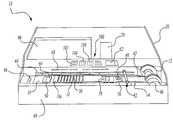
- FIG. 1is a perspective view of the automated slide staining system of the present invention.
- FIG. 2is a top view of the automated slide staining system of the present invention.
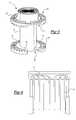
- FIG. 3is a perspective view of the slide storage device used in the staining system of the present invention.
- FIG. 4is a front view of the cannula tubes used in the staining system of the present invention.
- FIG. 5is a perspective view of a bottle which is used to hold the staining fluids used in the automated slide staining system of the present invention.
- FIG. 6is an enlarged view of the cover slip apparatus used in the second embodiment of the present invention.
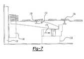
- FIG. 7is a side view of the cover slip apparatus having the rack secured thereto, used in the second embodiment of the present invention.
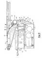
- FIG. 8is a cross-sectional view of the cover slip apparatus used in a further embodiment of the present invention.
- FIG. 9is another cross-sectional view of the cover slip apparatus used in a further embodiment of the present invention.
- FIG. 10is a side view of the cover slip apparatus with an optical sensor attached thereto.
- the present inventionis an automatic slide staining system 10 comprising a slide storage device 12 , a slide transport apparatus 14 , and a processing platen 16 including a plurality of staining stations 18 .
- the slide storage device 12is designed and configured to removably receive slides (not illustrated), such as cytology or histology. As such, this slide storage device 12 is removably secured to the base of the system.
- the slide storage devicealso known as a carousel, is illustrated in further detail in FIGS. 1, 2 , and 3 . When secured, the slide storage device 12 will be disposed in a horizontal position, as seen in FIGS. 1 and 2.
- This slide storage device or carousel 12is removably secured to a shaft (not illustrated) of a first motor (stepper motor) 22 . Once the machine is activated, the first motor is initiated to provide for the shaft to rotate. The slides are then individually discharged onto slide transport apparatus 14 in order to be processed on the various stations 18 of the processing platen 16 .
- the carousel 12as illustrated in these drawings and in further detail in FIG. 3, has an upper portion 24 and a lower portion 26 .
- the upper and lower portionsare substantially identical in shape and size.
- the upper and lower portions 24 and 26respectively, each have an inner surface 28 and an outer surface 30 .
- the inner surface 28 of the upper portion 24faces the inner surface 28 of the lower portion 26 .
- Centrally located in each of the portionsis an aperture (not illustrated).
- a hollow rod 32Located between the upper portion and lower portion is a hollow rod 32 .
- the rodhas a first end 34 and a second end 36 .
- the first and second endsare received in the apertures, which are located in the upper and lower portion, respectively.
- the shaft of the first motor on the staining apparatusreceives the hollow rod. This provides for the slide storage device to have a horizontally disposed central axis once it is secured to the shaft.
- a plurality of radially oriented wallsis provided along the inner surface of the upper and lower portion. These walls form a plurality of compartments 38 .
- a retainer spring 40is oriented between two adjacent walls for permitting releasable securement of the slide within the compartment. This retainer spring will permit for the carousal to accept slides of arbitrary thickness.
- This slide transport apparatuscomprises a first pair of conveyor belts 42 and a second pair of conveyor belts 44 .
- the design and structure of the conveyor beltspermit a means of releasing the stained slides from the carousel and a means of transporting the slides to the various stations.
- the first pair 42 of conveyor beltsare parallel to each other and are located between the carousel and staining stations.
- the second pair 44 of conveyor beltsare parallel to each other and are located below and along the sides of the processing stations.
- the first pair of conveyer beltsextend around a first pulley 46 and a second pulley 48 (partly illustrated).
- the second pair of conveyor beltsextend around a third pulley and a fourth pulley (neither illustrated).
- the first pulleyis located within a housing 20 and is in the proximity of the carousel 12 .
- the second pulleyis located within the housing and is in the proximity of the first staining station.
- the third pulleyis located next to the second pulley and the fourth pulley is located at the far end of the first platen.
- the conveyor beltsfurther include a plurality of evenly spaced rods or pips 50 , which protrude vertically and beyond the processing stations.
- the rods or pips 50 in each pair of beltsare in co-alignment.
- the beltsstart to rotate about the pulleys. This provides for the rods or pips 50 from the first pair of belts 42 to push on the edge of a slide in the carousel 12 . This causes the slide to be horizontally released from the carousel 12 and onto the belt 42 to provide for the specimen to be traveling in a downward position.
- a roller 52is located adjacent to the carousel 12 to ensure that the slide in secured on the belt as it is released from the storage device 12 .
- the slideWhile traveling on the first pair of conveyor belts 42 , the slide will pass under an optical sensor (not illustrated). This optical sensor will initiate the count of the individually transferred slides as each slide engages onto the first belts 42 prior to the staining process.
- this optical sensorcan be replaced with a microswitch, in order to activate the unit.
- the slideis then transported from the first pair of belts 42 to the second pair of belts 44 to permit for the rods or pips 50 from the second pair of belts 44 to aid in the transportation of the slide by driving it to the various processing stations.
- a second motor (stepper motor) 54is utilized to control and activate the first and second pairs of conveyor belts. This will provide for the slides to move at a constant rate of motion over the staining stations.
- the slide transport apparatusfurther includes an override switch for disengaging the stepper motor and stopping the movement of the slide transport apparatus when an alarm condition has been detected.
- the processing platen 16 of the automated slide staining system 10includes staining stations 18 .
- the staining stationshave a unique design and configuration. As illustrated in the figures (FIGS. 1 and 2 ), located at the comer of each station 18 is an aperture 56 . These apertures 56 allow for a staining fluid to be dispensed in a capillary form between the underside of the slide and the upper surface of each staining station.
- the stations 18are configured to be on the processing platen 16 at an acute angle. This acute angle aids in the flow of the staining fluid on the slide and also aids in the removal of the chemical as the slide is leaving the respective station.
- the processing platen 16further includes a plurality of troughs 58 , which are situated between each station, and reservoirs (not illustrated), which are located in the front of the staining stations 18 .
- a drainage orifice(not illustrated) is located within each reservoir.
- a waste tank(not illustrated) is underneath the first platen. This arrangement provides for the excess staining fluid from each station to flow into the troughs and to the reservoir. From the reservoir, the excess fluid flows into the waste tank via the drainage orifices.
- the waste tankcan easily be removed from the housing via a first door 60 .
- a display window 62which is located on the front of the slide staining system 10 , alerts the operator to empty and disposed of the fluid in the waste tank once a certain number of slides (i.e. 500) have been processed.
- the combination of the stationbeing situated at acute angles and the location of the troughs provides for the staining fluid from the preceding station not to carry over to the succeeding station.
- the last dispensing station 18 a of the staining systemdispenses a resin solution onto the slide. Adjacent to the last station is a heating station. After the resin solution has been dispensed onto the slide, it will travel to the heating station.
- the heating stationconsists of a convector 64 , which will enable the resin solution to dry so that the tissue specimen, located on the slide, will be sealed. This seal creates a protective coating so that the specimen will be in a sterile and contaminant free environment.
- each slideis directed to a slide receptacle 66 .
- This slide receptaclereceives and maintains the slides after a complete traverse of the slide staining stations.
- the automated slide staining systemalso includes a fume extractor means.
- the fume extractor meansremoves the toxic fumes generated by the staining fluids during the dispensing cycle.
- the fume extractor meanscomprises of a plurality of openings 68 , located above the staining stations, a charcoal filter within a housing 70 , and an exhaust 72 having an exhaust fan.
- a cover or hood 74is located above the staining stations 18 in order to trap the fumes from the staining solutions. This will enable them to be extracted from the area of the staining stations by way of the plurality of the openings 68 .
- the charcoal filterabsorbs the toxic fumes from the staining solution, while the exhaust fan which is controlled by a third motor 76 , disposes the purified fumes from the automated slide staining system 10 via the exhaust 72 .
- the charcoal filter 70can be remove and replaced simply by opening a second door 78 on the housing. This second door 78 exposes the filter's housing 70 and permits for it to be open so that the filter can be removed and/or replaced.
- the staining fluid used in the automated slide staining systemtravels to its respective station via polytetraflouroethlyene (PTFE or TEFLON) transfer tubings 80 , as seen in FIGS. 2 and 4.
- PTFE or TEFLONpolytetraflouroethlyene transfer tubings 80 , as seen in FIGS. 2 and 4.
- Each tubecomprises a first end and a second end. The first end is inserted to the underside of the staining station and into the aperture. The second end is attached to a cannula tube 82 .
- the cannula tubes 82 as illustrated in FIG. 2 and as further illustrated in FIG. 4are inserted into a plurality of containers 84 containing a staining fluid. These tubes are connected to a pump 86 to permit for the staining fluid to flow from the cannula tube 82 to the aperture of the staining station via the transfer tubing 80 .
- the pumpis controlled by a fourth motor (illustrated but not labeled).
- the combination of the cannula tubes and the transfer tubingis also referred to as a channel.
- Each tubingis connected to a solenoid valve 88 .
- the valve 88controls the directional flow of the fluid.
- valveWhen the valve is in a closed position, the fluid is recirculating within the channel, while when the valve is in an open position, the fluid is diverted to the aperture within a station.
- a microprocessoractivates the valve, for that particular station, to an open position. This will divert the fluid and provide for that fluid to be dispensed onto the particular station.
- the second motor(stepper motor) is utilized for actuating the conveyor belts in order to guide the slides along the first platen of the staining system.
- a microprocessorlocated within the electric bay 90 ) is used to count the steps or distance that each slide travels. When a slide reaches a particular and predetermined distance, the microprocessor will activate the solenoid valve so that the staining fluid for a particular station can be diverted to that station. The solenoid valve will remain open until the slide has traveled a certain or predetermined distance, at which time the microprocessor will send a signal to close the solenoid valve. This closure of the solenoid valve will provide for the fluid to recirculate within its respective channel.
- each of the staining bottlesincludes an aperture 92 for receiving the cannula tube and two side walls 94 , which are substantially longer than the front wall 96 and rear wall (not shown).
- the containersare placed in a box to provide for contact to be made with the container side walls (see FIG. 2 ).
- This boxis placed within the housing via a third door 98 (see FIG. 1) of the automated slide staining system 10 .
- This arrangementpermits for the installation and replacement of the staining fluids to be made quickly and efficiently by removing the box holding the plurality of containers.
- the four digit LED display window 62is located above the processing platen 16 .
- Located in the proximity of the display window 62is a plurality of keys or buttons 100 .
- the keys or buttonsrepresent the number of slides which are being processed in a particular batch 106 , the speed of which the slides are traveling 104 , and the number of slides which can be processed by utilizing the remaining staining fluid located in the containers 102 .
- the four digit LED display windowwill enable an operator to display the desired key indication.
- the speed at which the slides travelcan be adjusted by the utilization of the speed button 104 .
- This speed buttonwill not only display the speed at which the slides are traveling, but will also permit the user to alter the speed. This change of speed will alter the intensity and contrast of the stain with respect to the tissue specimen.
- an operatorinserts stained slides into the compartments 38 of a storage device or carousel 12 .
- the slidesare secured in the storage device by springs 40 , which are located inside each storage compartment.
- the storage deviceis removably secured to a shaft. Once secured, the operator can then activate the power supply 108 of the staining system 10 by using a button to provide for the shaft to rotate, inherently causing the storage device 12 to rotate. The activation of the system will also initiate the conveyor belts 42 and 44 .
- the rods or pips 50 on the beltspush or force a slide to exit the storage container 12 .
- the slideis released from the storage container so that the specimen is facing in a downward position.
- the second motor 54is used to control and operate the conveyor belts. The use of the first and second motors (stepper motors) and the arrangement and spacing of the rods or pips will permit for the slides to be released one at a time.
- the slideAfter release from the storage device, the slide first contacts an optical sensor (or optionally, a microswitch).
- the optical sensor(or optionally, the microswitch) initiates the count of the individually transferred slide. After contact with the optical sensor the slide is transferred to the staining stations 18 via the second set of conveyor belts 44 .
- the pulses that the microprocessor uses to drive a second motor 54 which powers the second set of conveyor beltsare used to determine when the microprocessor will activate the solenoid valve for a particular station. Once a slide reaches a particular and predetermined distance, the microprocessor will transmit a signal to activate or open the solenoid valve of a particular station. This will enable the staining fluid to flow to the appropriate staining station. The solenoid valve will remain open until the slide has traveled a certain or predetermined distance, at which time the microprocessor will send a signal to close the solenoid valve.
- the particular distance in this system for activation of the solenoid valveoccurs when the slide is directly above the aperture in the station.
- the particular distance in which a signal will be transmitted to deactivate the systemwill occur when the slide exits that particular station.
- the processing of the slidesis continued until the slide reaches the heating station, which includes the convector 64 . At this time the resin coating, which was applied at the last dispensing station 18 a, is dried. This will provide for the slide to have a protective resin coating. After the resin has dried, the slide will be transported and dropped into a slide receptacle 66 .
- the automated slide staining systemwill continue to release the slides from the storage device. This will continue until all the slides have been released or if there is not a sufficient amount of staining fluid to process the slides.
- a heating unitis provided after the last dispensing station.
- the automated slide staining systemcan be arranged such that a cover slip can be dispensed, one at a time, in order to apply it on a slide. This alteration is illustrated in further detail in FIGS. 6 and 7.
- the cover slipper apparatusincludes a separate platen 120 , which is located in the proximity of the last station of the processing platen 16 .
- This separate platen or transporting platen 120includes a first end 122 , a middle area 124 , and a second end 126 .
- This first end of the platenis at an obtuse angle with respect to the middle area.
- the first end 122is located in the proximity above the distribution end of a dispenser tray 110 , which houses the slides.
- the middle portion 124 to the second end of the transporting platen 120is linear.
- the middle area of the platenis in the proximity of the processing platen 16 .
- a third pair of conveyor beltsare located on the edge of the platen 120 . Extending vertically and outwardly from these belts are a plurality of evenly spaced rods or pips (illustrated, but not labeled).
- the receptacle or dispenser tray 110 of the cover slip apparatuswhich holds and maintains the cover slips provides for the cover slips to be held in a horizontally oriented position.
- This receptacle 110can be secured to apparatus by the use of securing brackets (illustrated, but not labeled), a supporting platform 134 , a combination thereof, or any conventional attaching means. Holding brackets, illustrated but not labeled, are not necessary for attaching the cover slip apparatus to the housing 20 , but are necessary for maintaining the various components of the cover slip apparatus.
- the holding receptacle 110further includes an opened end which allows for the removal of the cover slips therein, thereby providing for the open end to face the processing platen 16 . If a supporting platform 134 is utilized then the electrical components which control the cover slip apparatus are housed therein. Optionally, if the supporting platform is not used, then the electrical components which control the cover slip apparatus are housed within the housing 20 (illustrated in FIGS. 1 and 2 ).
- a tension block 136is slidably secured to the dispenser tray 110 for providing the cover slips to be held in position by the rear block which is pulled by a spring. Such an arrangement forces the slips to be pressed up against a pair of rollers, also known as the first roller and second roller.
- a handle 138Extending outwardly from the tension block 136 is a handle 138 .
- a meanscan be provided for enabling the tension block to remain in a compressed state for loading. Such a means can be conventional, such as providing an extension that is adapted to contact the spring and allow the spring to be maintained in a compressed stated.
- the handle 138permits the user to expose the dispenser tram for reloading of cover slips.
- the tension blockcan be magnetically held in position in order to allow the user to quickly and efficiently fill the receptacle.
- the cover slip apparatus of the present inventionfurther includes a releasing means for releasing the cover slips from the holding receptacle.
- the releasing meansincludes a plurality of rollers.
- a first roller or ejector roller 140which is controlled by a first motor housed either in the housing 20 or in the platform 134 , ejects or removes the cover slip from the receptacle to a second roller 142 .
- This first roller 142is located in front of the open end of the holding receptacle 110 and will contact the first or exposed cover slip.
- the second roller 142like the first roller, is controlled by a second motor, also housed in the supporting platform 134 or housing 20 . Once the cover slip reaches the second roller 142 , the rotation of the first roller 140 ceases. Once this roller 140 ceases, the secondary roller 142 rotates in order to guide the cover slip to the third roller or positioning roller 144 .
- This third roller or position roller 144is fabricated from a durable and heavy material, such as stainless steel and is located above the secondary roller in order to ensure that the cover slip is properly positioned on the transport apparatus. As seen, this third roller 144 is maintained on a pair of slots (illustrated, but not labeled) and is therefore adapted to move freely along the slots.
- the cover slipwhen the cover slip approaches the third roller 144 , it is displaced and will inherently push the cover slip forward and onto the first end 122 of the second platen 120 .
- the slidewhich includes the resin material, will contact the cover slip to provide for the cover slip to be secured to the slide.
- the rack 146is situated over a heating source 148 for adequately and efficiently drying the resin and securing the cover slip on the slide.
- the activation of the automated slide staining systemwill provide for the third set of conveyor belts to be activated. This activation will permit for the utilization of the cover slip apparatus.
- a pair of shafts(not illustrated), preferably fabricated from stainless steel, are mounted above the cover slip dispenser and above the first roller.
- the first shaftis mounted in a fixed position and the second shaft is mounted so that it's ends floats in respective C-shaped cups.
- the first shaftlike the cover slips and rollers, is disposed horizontally and is aligned with the opened end of the holding receptacle.
- the second shaftis parallel to the first shaft and can move freely within the C-shaped cups. These C-shaped cups are secured to the bracket, illustrated, but not labeled. Hence, as the cover slip is removed, it extends between the two shafts. The upward motion of the cover slip forces the second shaft to move via the C-shaped cups. This movement causes a gap to be located between the first shaft and second shaft. The gap is of a sufficient dimension to enable only one cover slip to pass therethrough and to contact the second roller.
- the cover slip apparatusincludes an additional safety measure by providing a means of removing resin if a cover slip is not introduced onto the slide.
- This resin removing meanscomprises a bar 150 located at a distant end of reservoir 152 . As the slide having no cover slip attached thereon contacts the bar 150 , the resin will be scraped and transferred into the reservoir 152 . The ends of the bar 150 will allow gravity to force the resin down into the reservoir 152 .
- This barcan be designed such that it includes tapered ends. This will provide for the bar to have a tip and the tip portion can be-used to scrap the resin. The tapered ends will guide the excess resin down into the respective reservoir.
- the cover slip apparatusfurther includes a neutralizing means 154 for dissipating any potential electrostatic charge, which may occur, as the cover slip is removed from the receptacle 110 .
- This neutralizing means 54is conventional and can include any commercially available and safe radioactive product.
- the rackis illustrated in further detail in FIGS. 6 and 7. As seen in these drawings, the rack 146 is located at end of the cover slip apparatus. This design and configuration will allow for the covered slides to be stored safely therein. Located on the outer end of the cover slip apparatus, on the opposite end of the releasing means, is a conventional heating unit 156 . This heating unit 156 will supply appropriate heat for adequately and efficiently drying and curing the resin. This will provide for the cover slip to be secured to the slide.
- the storage rack 146is controlled by a storage rack drive unit 158 .
- This unit 158is coupled to the rack 146 and enable the rack to shift upward once a slide is located therein.
- the unit 158is conventional and permits for the apparatus to extend upwards accordingly.
- An optical sensoris located within the storage rack drive unit 158 for sensing and detecting when the rack should be incremented.
- This second embodimentfurther includes a second sensor, which will detect when the cover slip dispenser tray is empty. If the dispenser tray is empty, a warning will be displayed on the front panel of the LED display window.
- the last station 18 ais situated below the other stations. This design and configuration will provide for a gap to exist between the stained slide and station. The resin is then dispersed quickly from the apertures (illustrated, but not labeled).
- the apertures on the last stationare so designed so that two drops are dispersed on the lower surface of the slide.
- a separate pumpis used for dispersing the resin. This separate pump can be located within the housing 20 .
- the apertures for the last stationare sized such that a minimal amount of resin is extracted therefrom. A size for the apertures of approximately 0.013 inches in diameter has been used successfully.
- the utilization of the automated slide staining system in conjunction with the present inventionis similar to the use of the system with the heating station, except that in this embodiment the heating station is replaced with the cover slip storage and dispensing apparatus.
- the processing of the slidesis continued until the slide reaches the cover slip apparatus.
- the resin coatingwhich is preferably distributed utilizing two apertures, applied at the last dispensing station, acts as an adhesive for the cover slip.
- the microprocessordetects its presence of the slide and will send a signal for proper activation of the cover slip apparatus.
- This signalwill activate the first motor.
- This motorturns the first roller. Since this roller contacts the first exposed cover slip as it rotates, clockwise, it inherently lifts the front cover slip.
- This cover slipthen contacts the parallel shafts. As it moves upwards via the first roller, it forces the second shaft to move causing a gap to be located between the first and second shaft.
- the cover slippasses through the two shafts. This gap is of a dimension wherein only one cover slip can extend therethrough.
- the gapis set by feeler gages, preferably, to 0.008 inches.
- an optical switchdetects a slot cut in the flange of the pulley mounted on the motor drive shaft. This optical switch activates the electronics for deactivating the first motor and activation the second motor. The deactivation will cease rotation of the first roller while the activation of the second motor will cause the second roller to activate. At this point the cover slip has been dispensed in an upward direction by the first roller and through the pair of shafts.
- This second roller and the entire cover slipper dispenserare mounted so as to be in contact with the third roller. Since the third roller is an idler roller mounted at the end of the cover slipper platen, it will consequently position the cover slip accordingly. As the second motor drives the second roller in a clockwise direction, it lifts the cover slip upward. At this point the cover slip is still being dispensed in a vertical direction. As it passes through the second roller it has to be tilted to the left so that it will lay at an angel of approximately 25 degrees onto the cover slipper platen, where it can be picked up by the drive belts and transported up to meet an oncoming slide.
- the third or free floating rolleris utilized. As the slide is lifted up it moves this roller backwards in its slots. As soon as the slip is clear of the second roller, the weight of the free floating roller is sufficient to force the slip to tilt over and lay on the platen.
- the slip once ejectedis guided into position on the cover slipper platen by an angled side on the platen. This forces the slip, as it is picked up by the belt's pips, to move into its correct position.
- the slipis then transported up the cover slipper platen at an angle to the oncoming slide that is to be cover.
- the oncoming slide at the last station of the platenhas received two jets of resin. These two jets have deposited two drops of resin to the underside of the slide.
- the slidecontinues with the two drops until it reaches a section of the rails, along which it is traveling, where it is tilted down very slightly at its front edge. This action allows the drops to run forward towards the front edge of the slide.
- the cover slip leading edgeis also very close to the leading edge of the slide, but still at a slight angle to it.
- the drops of resincatch the cover slip and form a pool of liquid at the leading edge of the slide and slip.
- the resinis held between these two surfaces by surface tension.
- the angle of the slipis further decreased and capillary action takes over causing the resin to flood rearwards across the face of the slide and slip.
- This actionalso causes the slip to be pulled up onto the slide.
- This actionalso causes any air to be pushed out by the action of the resin flooding across the slide, so that no air bubbles are trapped between the glass surfaces.
- the action of the resin flowing from front to rear across the face of the slidecauses an equal and opposite effect as in Newton's Laws of motion, thus allowing the slip to move from just rear of the front of the slide to actual being centered on the slide.
- the cover slipped slideis then transported to the end of the platen where it is loaded into a pair of slots in the rack collection unit. It finally stops being moved once it is entered into the rack and it comes to rest over a heater plate. The heater dries the edges of the slide and slip sufficiently to hold the two in place.
- the resincontains Toluene, which will evaporate quickly at a low temperature.
- the rackis incremented up one pair of slots at a time to allow the slide to be loaded into it in the same sequence as they left the carousel.
- the rackcan be removed with the slides in it and taken for reading, as these are completely processed slides. The process is continued until the rack is completely occupied or the cover slip receptacle or is emptied.
- each station and the number of stations used in the first or second embodimentcan be changed in order to accommodate the testing that is desired (i.e. histology versus cytology).
- the method involved in the processing of a histology tissue specimen using the automated slide staining system of the present inventionincludes a plurality of different solutions to be dispensed at each station.
- the paraffinis removed from the tissue by the use of xylene.
- the specimenis then hydrated with ABS alcohol (second station) followed by a hydration of diluted alcohol (third station).
- the cell nuclei of the specimenare then treated with a hematoxylin compound (fourth station).
- the next stepis to remove the excess stain from the specimen using a diluted acid compound (fifth station).
- the specimenis dehydrated by using a pure alcohol (sixth station).
- the enhancing of the nuclear staincontrast with respect to the specimen using a dilute alkali solution (seventh station).
- the specimenis then dehydrated by the use of pure alcohol (eighth station).
- the specimenis then stained for cytoplasm by using an eosin compound (ninth station). Again the specimen is dehydrated, this time by the use of ABS alcohol (tenth station). Further dehydration of the specimen occurs with a solution of 50 percent ABS alcohol and 50 percent xylene (eleventh station)
- the specimenis cleaned using a xylene solution (twelfth station).
- a coatingis applied to the slide for maintaining the specimen to be in a contamination free status (thirteenth station).
- the slideis either transported to a drying station or to a cover slip area.
- the method involved in the processing of a cytology tissue specimen using the automated slide staining system of the present inventionincludes a plurality of different solutions to be dispensed at each station.
- the specimenis hydrated with an alcohol solution.
- the specimenis hydrated again with a second alcohol solution (second station).
- the plurality of cell nuclei of the tissue specimenis processed with a hematoxylin stain compound (third station).
- Excess staining materialis then removed from the specimen with a diluted acid solution (fourth station).
- the specimenis dehydrated with an alcohol solution (fifth station).
- the next stepis for enhancing the nuclear staining contrast of the tissue specimen with a dilute alkali solution (sixth station).
- the specimenis dehydrated with an alcohol solution (seventh station).
- the next stepis to counterstain the specimen for highlighting cytoplasmic cell material (eighth station).
- the removal of the excess staining material from the tissue specimenis the next step (ninth station).
- Counterstaining the specimen for cytoplasmic cell contrastthen occurs (tenth station).
- the specimenis then dehydrated with ABS alcohol (eleventh station). Further dehydration of the specimen occurs with a second dispensing of ABS alcohol (twelfth station).
- the specimencan be dehydrated with a solution of 50 percent ABS alcohol and 50 percent xylene.
- the specimenis then cleaned with a xylene compound (thirteenth station).
- a coatingis applied to the slide for maintaining the specimen to be in a contamination free status (fourteenth station).
- the slideis either transported to a drying station or to a cover slip area.
- FIGS. 8 through 10illustrate an alternative approach for dispensing a cover slip 170 one at a time by way of a cover slipper apparatus 172 .
- cover slipper apparatus 172includes a separate platen called a transporting platen 120 that is located in the proximity of the last station of the processing platen 16 .
- Transporting platen 120includes a first end 122 , a middle area 124 , and a second end 126 .
- a receptacle or dispenser tray 110 ′ of the cover slip apparatus 172which holds and maintains cover slips 170 , provides for the cover slips to be maintained in a rest position in a vertical orientation with a face of a first cover slip in facial contact with a front wall 174 of tray 110 ′.
- a first edge 176 of each cover slip 170contacts the floor 177 of tray 110 ′ before it is placed in a dispensing position for release as described below.
- tray 110 ′may be secured to the apparatus by the use of securing brackets, a supporting platform 134 , a combination thereof, or any conventional means. If a supporting platform 134 is utilized then electrical components such as motors 178 and 180 are housed therein. Optionally, if the supporting platform 134 is not used, then the electrical components that control the cover slip apparatus are housed within housing 20 (illustrated in FIGS. 1 and 2 ).
- a tension block 136 with a handle 138is slidably secured to tray 110 for providing the cover slips to be held in position such that the slips are held in their vertical orientation between front wall 174 and tension block 136 .
- an adhesive resinis dispensed in the form of drops, via two jets 182 , to the underside of the slide.
- the microprocessorthen signals for the dispensing of a single cover slip 170 .
- tray 110 ′includes an opened end that acts as a release point and allows for the dispensing of the cover slips 170 therein.
- the release mechanism for dispensing a cover slipis different.
- Motors 178 and 180begin to turn.
- Motor 178turns drive gear 184 , which is in engagement with and thereby turns mating gear 186 .
- Gear 186is pivotally connected to a first opposing end 188 of a linear crank mechanism 190 .
- a second opposing end 191 of crank mechanism 190is pivotally connected to a slip lift 192 acting as an ejector.
- Slip lift 192is constrained between tray 110 ′ and a fixed vertically extending wall 194 such that it only can go up and down in response to circular movement of gear 186 .
- crank mechanism 190is used to convert rotational movement into linear movement.
- Slip lift 192includes a side surface that acts as front wall 174 of tray 110 and includes a very narrow ledge 196 at a bottom surface thereof, the ledge being generally perpendicular to front wall 174 .
- ledge 196In a rest position as shown in FIG. 8, ledge 196 is generally flush with or slightly below floor 177 of tray 110 ′. It must not be above the surface of floor 177 or the next available cover slip 170 cannot be advanced for release.
- the width of ledge 196is carefully controlled so as to correspond to the width of a single cover slip 170 .
- Gear 186 , crank mechanism 190 and slip lift 192are carefully sized such that as gear 186 rotates, a single cover slip 170 is vertically lifted out of tray 110 ′ in the direction of arrow A. When gear 186 rotates one-hundred and eight degrees (180°) from its rest position to an ejecting position, slip lift 192 is at its highest vertical position and a cover slip sufficiently clears tray 110 ′ to engage a transport
- a very narrow gapexists between wall 174 and a stripping bar 198 .
- Wall 174 and stripping bar 198act as a cover slip metering device in a manner similar to that discussed with respect to FIGS. 6 and 7.
- the stripping bar 198is adjustable.
- the stripping bar 198is adjusted to provide approximately a 0.009′′ (0.23 mm) opening with respect to wall 174 such that only a single cover slip 170 may pass there between. If two cover slips 170 are stuck together, the use of stripping bar 198 helps to separate the two covers lips.
- a cover slip 170exits tray 110 ′ and passes by stripper bar 198 , it comes into contact with a transport mechanism including a fixed driven roller 200 , which is driven by motor 180 .
- a biased idler roller 202opposes driven roller 200 and is in selective frictional engagement with it. Rollers 200 and 202 are positioned so that a covers slip 170 vertically exiting tray 110 ′ will engage the mating point between the two rollers to minimize unwanted initial distortion and to prevent accidental jamming upon removal from tray 110 ′. Since idler roller 202 is biased, cover slip 170 is able to pass through the mating point where the driven roller then propels the cover slip away from tray 110 ′.
- a free edge 204 of the cover slip 170 opposing edge 176passes through the mating point between rollers 200 and 202 .
- free edge 204passes through the mating point, it must be tilted so that it will lay at an angle of approximately twenty-five degrees (25°) on the transporting platen 120 as shown by arrows B, where it can be picked up by the drive belts acting as a drive mechanism and transported up to meet an on coming slide at a merge point as discussed above.
- a free-floating roller 206is used. As the cover slip is lifted by slip lift 192 and passes through mating rollers 200 and 202 , roller 206 is moved backwards in a slot 208 with a substantial vertical component.
- Roller 206is given sufficient weight such that as soon as free edge 204 is clear of roller 202 , the weight is sufficient to force the cover slip 170 to tilt over and lay on transporting platen 120 . Then the pips of the conveyor belt, take over and cover slip 170 is transported up platen 120 as discussed above with respect to FIGS. 6 and 7 so that it merges with an oncoming slide that is to be covered at merge point 210 .
- cover slipper mechanism 172is preferably equipped with an optical sensor 212 as best shown in FIG. 10 .
- Sensor 212monitors the movement of roller 206 , which must move if a slip is dispensed. If no movement is detected in the time period required to dispense two slips, then the device goes into an error mode.
- an audible alarmsignals the operator and an appropriate message concerning a problem with mechanism 172 is displayed;
- the cover slipper 170stops dispensing slips;
- jets 182are disabled;
- no additional slidesare dispensed from storage device or carousel 12 (shown in FIG. 1 ); and
- all slides that are in process on the platen 16are completed without a cover slip 170 .
Landscapes
- Health & Medical Sciences (AREA)
- Life Sciences & Earth Sciences (AREA)
- Engineering & Computer Science (AREA)
- Biomedical Technology (AREA)
- Molecular Biology (AREA)
- Physics & Mathematics (AREA)
- Chemical & Material Sciences (AREA)
- Analytical Chemistry (AREA)
- Biochemistry (AREA)
- General Health & Medical Sciences (AREA)
- General Physics & Mathematics (AREA)
- Immunology (AREA)
- Pathology (AREA)
- Sampling And Sample Adjustment (AREA)
Abstract
Description
Claims (16)
Priority Applications (1)
| Application Number | Priority Date | Filing Date | Title |
|---|---|---|---|
| US09/418,262US6387326B1 (en) | 1994-07-19 | 2000-02-09 | Automated slide staining system and method thereof |
Applications Claiming Priority (3)
| Application Number | Priority Date | Filing Date | Title |
|---|---|---|---|
| US08/277,170US5700346A (en) | 1994-07-19 | 1994-07-19 | Automated slide staining system |
| US08/995,461US6076583A (en) | 1994-07-19 | 1997-12-20 | Automated slide staining system |
| US09/418,262US6387326B1 (en) | 1994-07-19 | 2000-02-09 | Automated slide staining system and method thereof |
Related Parent Applications (1)
| Application Number | Title | Priority Date | Filing Date |
|---|---|---|---|
| US08/995,461Continuation-In-PartUS6076583A (en) | 1994-07-19 | 1997-12-20 | Automated slide staining system |
Publications (1)
| Publication Number | Publication Date |
|---|---|
| US6387326B1true US6387326B1 (en) | 2002-05-14 |
Family
ID=46276650
Family Applications (1)
| Application Number | Title | Priority Date | Filing Date |
|---|---|---|---|
| US09/418,262Expired - Fee RelatedUS6387326B1 (en) | 1994-07-19 | 2000-02-09 | Automated slide staining system and method thereof |
Country Status (1)
| Country | Link |
|---|---|
| US (1) | US6387326B1 (en) |
Cited By (52)
| Publication number | Priority date | Publication date | Assignee | Title |
|---|---|---|---|---|
| US20030003022A1 (en)* | 2001-06-29 | 2003-01-02 | Yoshiyuki Tamura | Automatic smear preparing apparatus and automatic sample analysis system having the same |
| US20030138355A1 (en)* | 2002-01-18 | 2003-07-24 | Yoshiyuki Tamura | Smear preparing apparatus |
| WO2003089140A1 (en)* | 2002-04-15 | 2003-10-30 | Ventana Medical Systems, Inc. | Automated high volume slide staining system |
| US20040005244A1 (en)* | 2002-07-05 | 2004-01-08 | Stefan Thiem | Drive system for an apparatus for staining specimens |
| US6756015B2 (en)* | 2000-08-22 | 2004-06-29 | Leica Microsystems Nussloch Gmbh | Apparatus for treating objects |
| US20040221477A1 (en)* | 2002-09-12 | 2004-11-11 | Lg Electronics Inc. | Structure of motor shaft in clothes dryer |
| US6827900B2 (en)* | 2000-02-11 | 2004-12-07 | Leica Microsystems Nussloch, Gmbh | Automatic stainer having a heating station |
| WO2004059288A3 (en)* | 2002-12-20 | 2005-01-27 | Dakocytomation Denmark As | Isolated communication sample processing system and methods of biological slide processing |
| US20050036911A1 (en)* | 2003-08-12 | 2005-02-17 | Sellers James M. | Slide cartridge and reagent test slides for use with a chemical analyzer, and chemical analyzer for same |
| US20050035156A1 (en)* | 2003-08-11 | 2005-02-17 | Michael Hersch | Fluid dispensing apparatus |
| US20050186114A1 (en)* | 2002-04-15 | 2005-08-25 | Kurt Reinhardt | Automated high volume slide processing system |
| US20060076257A1 (en)* | 2004-10-12 | 2006-04-13 | Robert Sakal | Transformable slide storage apparatus and method |
| US20060169719A1 (en)* | 2003-08-11 | 2006-08-03 | Bui Xuan S | Manifold assembly |
| US20060173575A1 (en)* | 2003-08-11 | 2006-08-03 | Gilles Lefebvre | Automated reagent dispensing system and method of operation |
| US20060171857A1 (en)* | 2003-08-11 | 2006-08-03 | Stead Ronald H | Reagent container and slide reaction and retaining tray, and method of operation |
| US20060263249A1 (en)* | 2002-01-18 | 2006-11-23 | Masanori Nakaya | Smear preparing apparatuses and methods of preparing sample smears |
| US20080089808A1 (en)* | 2006-10-17 | 2008-04-17 | Preyas Sarabhai Shah | Slide stainer with multiple heater stations |
| US20100008824A1 (en)* | 2003-12-04 | 2010-01-14 | Idexx Laboratories, Inc. | Retaining clip for reagent test slides |
| US20100144018A1 (en)* | 2008-12-10 | 2010-06-10 | Rushabh Instruments, Llc | Automated slide staining apparatus |
| US20100254854A1 (en)* | 2007-05-08 | 2010-10-07 | Idexx Laboratories, Inc. | Chemical analyzer |
| US8459509B2 (en) | 2006-05-25 | 2013-06-11 | Sakura Finetek U.S.A., Inc. | Fluid dispensing apparatus |
| WO2013071358A3 (en)* | 2011-11-16 | 2013-07-18 | Leica Biosystems Melbourne Pty Ltd | Biological sample treatment apparatus |
| CN103293034A (en)* | 2012-02-24 | 2013-09-11 | 奚金华 | Full-automatic pathological tissue slide-making system |
| US8580568B2 (en) | 2011-09-21 | 2013-11-12 | Sakura Finetek U.S.A., Inc. | Traceability for automated staining system |
| US8652408B2 (en) | 2004-12-23 | 2014-02-18 | Dako Instrumec As | Apparatus for execution of treatment operations on microscope slides with tissue specimens |
| US8752732B2 (en) | 2011-02-01 | 2014-06-17 | Sakura Finetek U.S.A., Inc. | Fluid dispensing system |
| WO2014132094A2 (en) | 2013-02-28 | 2014-09-04 | 3Dhistech Kft. | Automated integrated slide-processing system |
| US8932543B2 (en) | 2011-09-21 | 2015-01-13 | Sakura Finetek U.S.A., Inc. | Automated staining system and reaction chamber |
| WO2015086484A1 (en) | 2013-12-13 | 2015-06-18 | Ventana Medical Systems, Inc. | Automated histological processing of biological specimens and associated technology |
| WO2015086534A1 (en) | 2013-12-13 | 2015-06-18 | Ventana Medical Systems, Inc. | Staining reagents and other liquids for histological processing of biological specimens and associated technology |
| WO2015086485A1 (en) | 2013-12-13 | 2015-06-18 | Ventana Medical Systems, Inc. | Thermal management in the context of automated histological processing of biological specimens and associated technology |
| US9797916B2 (en) | 2014-01-10 | 2017-10-24 | Idexx Laboratories, Inc. | Chemical analyzer |
| JP2017226464A (en)* | 2016-06-24 | 2017-12-28 | Necエンベデッドプロダクツ株式会社 | Label sticking device and label sticking method |
| WO2018081142A1 (en)* | 2016-10-25 | 2018-05-03 | Abbott Laboratories | Assessment and control of reagents in automated slide preparation |
| US10018542B2 (en)* | 2009-12-09 | 2018-07-10 | Dako Denmark A/S | Apparatus and method for processing biological samples |
| CN108535079A (en)* | 2018-05-31 | 2018-09-14 | 广州江元医疗科技有限公司 | A kind of multi-functional slide fixation turntable |
| WO2018215844A2 (en) | 2017-05-26 | 2018-11-29 | Ventana Medical Systems, Inc. | Non-contact, on-slide fluid mixing |
| US10184862B2 (en) | 2008-11-12 | 2019-01-22 | Ventana Medical Systems, Inc. | Methods and apparatuses for heating slides carrying specimens |
| CN109374386A (en)* | 2018-12-27 | 2019-02-22 | 杨永俊 | Glass slide automated staining system |
| CN109612798A (en)* | 2018-12-25 | 2019-04-12 | 宁波察微生物科技有限公司 | A kind of glass slide dyeing, mounting, scanning integrated machine |
| WO2019101658A1 (en) | 2017-11-21 | 2019-05-31 | Ventana Medical Systems, Inc. | Contactless mixing using modulated air jets |
| US10656168B2 (en) | 2013-12-13 | 2020-05-19 | Ventana Medical Systems, Inc. | Automated processing systems and methods of thermally processing microscope slides |
| US11185440B2 (en) | 2017-02-02 | 2021-11-30 | Zoll Circulation, Inc. | Devices, systems and methods for endovascular temperature control |
| US11249095B2 (en) | 2002-04-15 | 2022-02-15 | Ventana Medical Systems, Inc. | Automated high volume slide processing system |
| US11353016B2 (en) | 2014-11-06 | 2022-06-07 | Zoll Circulation, Inc. | Heat exchange system for patient temperature control with easy loading high performance peristaltic pump |
| US11359620B2 (en) | 2015-04-01 | 2022-06-14 | Zoll Circulation, Inc. | Heat exchange system for patient temperature control with easy loading high performance peristaltic pump |
| CN115667874A (en)* | 2020-05-27 | 2023-01-31 | 安捷伦科技有限公司 | Apparatus and method for processing biological samples |
| US11571332B2 (en) | 2012-09-28 | 2023-02-07 | Zoll Circulation, Inc. | Intravascular heat exchange catheter and system with RFID coupling |
| DE102021129467A1 (en) | 2021-11-11 | 2023-05-11 | Bio-Gram Diagnostics GmbH | Device for staining biological specimens attached to a slide |
| US11951035B2 (en) | 2017-02-02 | 2024-04-09 | Zoll Circulation, Inc. | Devices, systems and methods for endovascular temperature control |
| US11977091B2 (en) | 2020-07-10 | 2024-05-07 | Idexx Laboratories Inc. | Point-of-care medical diagnostic analyzer and devices, systems, and methods for medical diagnostic analysis of samples |
| WO2024100187A1 (en) | 2022-11-11 | 2024-05-16 | Bio-Gram Diagnostics GmbH | Device for staining biological samples adhering to a specimen slide |
Citations (27)
| Publication number | Priority date | Publication date | Assignee | Title |
|---|---|---|---|---|
| US3431886A (en) | 1964-07-02 | 1969-03-11 | Miles Lab | Apparatus for applying liquid to slides |
| US3823845A (en) | 1973-07-18 | 1974-07-16 | Reserv A Roll Co | Top loading article dispenser |
| US3892197A (en) | 1974-04-22 | 1975-07-01 | Thomas D Kinney | Light microscopy processing apparatus |
| US3903908A (en) | 1972-11-01 | 1975-09-09 | Columbia Ind Developments Limi | Slide staining apparatus |
| US3939019A (en) | 1974-08-02 | 1976-02-17 | Pickett John E P | Covering apparatus and method for film mounted serial tissue sections |
| US4092952A (en) | 1977-08-19 | 1978-06-06 | Wilkie Ronald N | Automatic slide stainer |
| US4151809A (en) | 1976-10-08 | 1979-05-01 | Miles Laboratories, Inc. | System for evenly applying liquid to a surface |
| US4190420A (en)* | 1978-06-05 | 1980-02-26 | Eastman Kodak Company | Container for dispensing articles to an automated analyzer |
| US4190472A (en) | 1977-09-28 | 1980-02-26 | Alex Slonicki | Automated system for the application of coverglasses on histological and cytological slides |
| US4219529A (en) | 1977-11-28 | 1980-08-26 | Eastman Kodak Company | Incubator for chemical analyzer |
| US4482282A (en)* | 1982-01-11 | 1984-11-13 | John Mueller | Apparatus and method for supplying articles |
| US4537648A (en) | 1983-02-28 | 1985-08-27 | Sankyo Company Limited | Automatic specimen sealing system |
| US4651671A (en) | 1986-02-21 | 1987-03-24 | Pedersen Anders N | Continuous feed apparatus for staining specimens carried on slides |
| US4738824A (en) | 1986-10-14 | 1988-04-19 | Kabushiki Kaisha Tiyoda Seisakusho | Apparatus for dyeing specimens automatically preparatory to microscopic examination |
| US4936465A (en) | 1987-12-07 | 1990-06-26 | Zoeld Tibor | Method and apparatus for fast, reliable, and environmentally safe dispensing of fluids, gases and individual particles of a suspension through pressure control at well defined parts of a closed flow-through system |
| US5496517A (en)* | 1989-12-22 | 1996-03-05 | Beckman Instruments, Inc. | Laboratory workstation using thermal vaporization control |
| US5653942A (en)* | 1994-05-18 | 1997-08-05 | Fuji Photo Film Co., Ltd. | Chemical analysis element cartridge |
| US5670375A (en)* | 1996-02-21 | 1997-09-23 | Biomerieux Vitek, Inc. | Sample card transport method for biological sample testing machine |
| US5674454A (en)* | 1996-02-21 | 1997-10-07 | Bio Merieux Vitek, Inc. | Stacking disposal system for test sample cards or other similarly shaped objects |
| US5692867A (en)* | 1993-12-28 | 1997-12-02 | Ricoh Company, Ltd. | Parts supply system |
| US5700346A (en) | 1994-07-19 | 1997-12-23 | Edwards; Peter S. | Automated slide staining system |
| US5736101A (en)* | 1992-07-01 | 1998-04-07 | Rehring Diagnostics | Automated analytical instrument having a fluid sample holding tray transport assembly |
| US5854075A (en)* | 1995-06-07 | 1998-12-29 | Alpha Scientific Instruments, Inc. | Automatic blood film preparation method |
| US6001670A (en)* | 1996-11-18 | 1999-12-14 | Kabushiki Kaisha Shinkawa | Lead frame supplying method |
| US6017495A (en)* | 1995-11-17 | 2000-01-25 | Ljungmann; Torstein | Staining apparatus for staining of tissue specimens on microscope slides |
| US6074617A (en)* | 1998-07-10 | 2000-06-13 | Bayer Corporation | Stat shuttle adapter and transport device |
| US6076583A (en)* | 1994-07-19 | 2000-06-20 | Fisher Scientific Company | Automated slide staining system |
- 2000
- 2000-02-09USUS09/418,262patent/US6387326B1/ennot_activeExpired - Fee Related
Patent Citations (28)
| Publication number | Priority date | Publication date | Assignee | Title |
|---|---|---|---|---|
| US3431886A (en) | 1964-07-02 | 1969-03-11 | Miles Lab | Apparatus for applying liquid to slides |
| US3903908A (en) | 1972-11-01 | 1975-09-09 | Columbia Ind Developments Limi | Slide staining apparatus |
| US3823845A (en) | 1973-07-18 | 1974-07-16 | Reserv A Roll Co | Top loading article dispenser |
| US3892197A (en) | 1974-04-22 | 1975-07-01 | Thomas D Kinney | Light microscopy processing apparatus |
| US3939019A (en) | 1974-08-02 | 1976-02-17 | Pickett John E P | Covering apparatus and method for film mounted serial tissue sections |
| US4151809A (en) | 1976-10-08 | 1979-05-01 | Miles Laboratories, Inc. | System for evenly applying liquid to a surface |
| US4092952A (en) | 1977-08-19 | 1978-06-06 | Wilkie Ronald N | Automatic slide stainer |
| US4190472A (en) | 1977-09-28 | 1980-02-26 | Alex Slonicki | Automated system for the application of coverglasses on histological and cytological slides |
| US4219529A (en) | 1977-11-28 | 1980-08-26 | Eastman Kodak Company | Incubator for chemical analyzer |
| US4190420A (en)* | 1978-06-05 | 1980-02-26 | Eastman Kodak Company | Container for dispensing articles to an automated analyzer |
| US4482282A (en)* | 1982-01-11 | 1984-11-13 | John Mueller | Apparatus and method for supplying articles |
| US4537648A (en) | 1983-02-28 | 1985-08-27 | Sankyo Company Limited | Automatic specimen sealing system |
| US4651671A (en) | 1986-02-21 | 1987-03-24 | Pedersen Anders N | Continuous feed apparatus for staining specimens carried on slides |
| US4738824A (en) | 1986-10-14 | 1988-04-19 | Kabushiki Kaisha Tiyoda Seisakusho | Apparatus for dyeing specimens automatically preparatory to microscopic examination |
| US4936465A (en) | 1987-12-07 | 1990-06-26 | Zoeld Tibor | Method and apparatus for fast, reliable, and environmentally safe dispensing of fluids, gases and individual particles of a suspension through pressure control at well defined parts of a closed flow-through system |
| US5496517A (en)* | 1989-12-22 | 1996-03-05 | Beckman Instruments, Inc. | Laboratory workstation using thermal vaporization control |
| US5736101A (en)* | 1992-07-01 | 1998-04-07 | Rehring Diagnostics | Automated analytical instrument having a fluid sample holding tray transport assembly |
| US5692867A (en)* | 1993-12-28 | 1997-12-02 | Ricoh Company, Ltd. | Parts supply system |
| US5653942A (en)* | 1994-05-18 | 1997-08-05 | Fuji Photo Film Co., Ltd. | Chemical analysis element cartridge |
| US6076583A (en)* | 1994-07-19 | 2000-06-20 | Fisher Scientific Company | Automated slide staining system |
| US5700346A (en) | 1994-07-19 | 1997-12-23 | Edwards; Peter S. | Automated slide staining system |
| US5854075A (en)* | 1995-06-07 | 1998-12-29 | Alpha Scientific Instruments, Inc. | Automatic blood film preparation method |
| US6017495A (en)* | 1995-11-17 | 2000-01-25 | Ljungmann; Torstein | Staining apparatus for staining of tissue specimens on microscope slides |
| US5674454A (en)* | 1996-02-21 | 1997-10-07 | Bio Merieux Vitek, Inc. | Stacking disposal system for test sample cards or other similarly shaped objects |
| US5670375A (en)* | 1996-02-21 | 1997-09-23 | Biomerieux Vitek, Inc. | Sample card transport method for biological sample testing machine |
| US6001670A (en)* | 1996-11-18 | 1999-12-14 | Kabushiki Kaisha Shinkawa | Lead frame supplying method |
| US6033932A (en)* | 1996-11-18 | 2000-03-07 | Kabushiki Kaisha Shinkawa | Lead frame supplying apparatus |
| US6074617A (en)* | 1998-07-10 | 2000-06-13 | Bayer Corporation | Stat shuttle adapter and transport device |
Non-Patent Citations (2)
| Title |
|---|
| Patent Abstracts of Japanese Patent No 60 011136 dated Jun. 20, 1983 for Method and Device for Dyeing Microscope Specimen. |
| Supplementary Partial European Search Report for Application No. EP 95 93 6781. |
Cited By (134)
| Publication number | Priority date | Publication date | Assignee | Title |
|---|---|---|---|---|
| US6827900B2 (en)* | 2000-02-11 | 2004-12-07 | Leica Microsystems Nussloch, Gmbh | Automatic stainer having a heating station |
| US6756015B2 (en)* | 2000-08-22 | 2004-06-29 | Leica Microsystems Nussloch Gmbh | Apparatus for treating objects |
| US20030003022A1 (en)* | 2001-06-29 | 2003-01-02 | Yoshiyuki Tamura | Automatic smear preparing apparatus and automatic sample analysis system having the same |
| US7297311B2 (en)* | 2001-06-29 | 2007-11-20 | Sysmex Corporation | Automatic smear preparing apparatus and automatic sample analysis system having the same |
| US8449822B2 (en) | 2002-01-18 | 2013-05-28 | Sysmex Corporation | Smear preparing apparatuses and methods of preparing sample smears |
| US20060263249A1 (en)* | 2002-01-18 | 2006-11-23 | Masanori Nakaya | Smear preparing apparatuses and methods of preparing sample smears |
| US7368080B2 (en)* | 2002-01-18 | 2008-05-06 | Sysmex Corporation | Smear preparing apparatus |
| US20030138355A1 (en)* | 2002-01-18 | 2003-07-24 | Yoshiyuki Tamura | Smear preparing apparatus |
| US8663991B2 (en) | 2002-04-15 | 2014-03-04 | Ventana Medical Systems, Inc. | Automated high volume slide processing system |
| US10302665B2 (en) | 2002-04-15 | 2019-05-28 | Ventana Medical Systems, Inc. | Automated high volume slide processing system |
| WO2003089140A1 (en)* | 2002-04-15 | 2003-10-30 | Ventana Medical Systems, Inc. | Automated high volume slide staining system |
| US20080038836A1 (en)* | 2002-04-15 | 2008-02-14 | Kurt Reinhardt | Automated high volume slide staining system |
| US11092611B2 (en) | 2002-04-15 | 2021-08-17 | Ventana Medical Systems, Inc. | Automated high volume slide processing system |
| US20050186114A1 (en)* | 2002-04-15 | 2005-08-25 | Kurt Reinhardt | Automated high volume slide processing system |
| US11249095B2 (en) | 2002-04-15 | 2022-02-15 | Ventana Medical Systems, Inc. | Automated high volume slide processing system |
| US20040002163A1 (en)* | 2002-04-15 | 2004-01-01 | Ventana Medical Systems, Inc. | Automated high volume slide staining system |
| US8048373B2 (en) | 2002-04-15 | 2011-11-01 | Ventana Medical Systems, Inc. | Automated high volume slide staining system |
| US9528918B2 (en) | 2002-04-15 | 2016-12-27 | Ventana Medical Systems, Inc. | Automated high volume slide processing system |
| US7468161B2 (en)* | 2002-04-15 | 2008-12-23 | Ventana Medical Systems, Inc. | Automated high volume slide processing system |
| US7303725B2 (en) | 2002-04-15 | 2007-12-04 | Ventana Medical Systems, Inc. | Automated high volume slide staining system |
| US7198752B2 (en)* | 2002-07-05 | 2007-04-03 | Leica Microsystems Nussloch Gmbh | Drive system for an apparatus for staining specimens |
| US20040005244A1 (en)* | 2002-07-05 | 2004-01-08 | Stefan Thiem | Drive system for an apparatus for staining specimens |
| US7661202B2 (en)* | 2002-09-12 | 2010-02-16 | Lg Electronics Inc. | Structure of motor shaft in clothes dryer |
| US20040221477A1 (en)* | 2002-09-12 | 2004-11-11 | Lg Electronics Inc. | Structure of motor shaft in clothes dryer |
| US7937228B2 (en) | 2002-12-20 | 2011-05-03 | Dako Denmark A/S | Information notification sample processing system and methods of biological slide processing |
| WO2004059288A3 (en)* | 2002-12-20 | 2005-01-27 | Dakocytomation Denmark As | Isolated communication sample processing system and methods of biological slide processing |
| US7400983B2 (en) | 2002-12-20 | 2008-07-15 | Dako Denmark A/S | Information notification sample processing system and methods of biological slide processing |
| US8969086B2 (en) | 2002-12-20 | 2015-03-03 | Dako Denmark A/S | Enhanced scheduling sample processing system and methods of biological slide processing |
| US10156580B2 (en) | 2002-12-20 | 2018-12-18 | Dako Denmark A/S | Information notification sample processing system and methods of biological slide processing |
| US8529836B2 (en) | 2002-12-20 | 2013-09-10 | Dako Denmark A/S | Apparatus for automated processing biological samples |
| US7648678B2 (en) | 2002-12-20 | 2010-01-19 | Dako Denmark A/S | Method and system for pretreatment of tissue slides |
| US20060063265A1 (en)* | 2002-12-20 | 2006-03-23 | Dakocytomation Denmark A/S | Advance programmed sample processing system and methods of biological slide processing |
| US8784735B2 (en) | 2002-12-20 | 2014-07-22 | Dako Denmark A/S | Apparatus for automated processing biological samples |
| US8663978B2 (en) | 2002-12-20 | 2014-03-04 | Dako Denmark A/S | Method and apparatus for automatic staining of tissue samples |
| US7758809B2 (en) | 2002-12-20 | 2010-07-20 | Dako Cytomation Denmark A/S | Method and system for pretreatment of tissue slides |
| US9229016B2 (en) | 2002-12-20 | 2016-01-05 | Dako Denmark A/S | Information notification sample processing system and methods of biological slide processing |
| US9778273B2 (en) | 2002-12-20 | 2017-10-03 | Dako Denmark A/S | Isolated communication sample processing system and methods of biological slide processing |
| US8788217B2 (en) | 2002-12-20 | 2014-07-22 | Dako Denmark A/S | Information notification sample processing system and methods of biological slide processing |
| US9599630B2 (en) | 2002-12-20 | 2017-03-21 | Dako Denmark A/S | Method and apparatus for automatic staining of tissue samples |
| US8394635B2 (en) | 2002-12-20 | 2013-03-12 | Dako Denmark A/S | Enhanced scheduling sample processing system and methods of biological slide processing |
| US7960178B2 (en) | 2002-12-20 | 2011-06-14 | Dako Denmark A/S | Enhanced scheduling sample processing system and methods of biological slide processing |
| US8386195B2 (en) | 2002-12-20 | 2013-02-26 | Dako Denmark A/S | Information notification sample processing system and methods of biological slide processing |
| US8298815B2 (en) | 2002-12-20 | 2012-10-30 | Dako Denmark A/S | Systems and methods of sample processing and temperature control |
| US8216512B2 (en) | 2002-12-20 | 2012-07-10 | Dako Denmark A/S | Apparatus for automated processing biological samples |
| US8257968B2 (en) | 2002-12-20 | 2012-09-04 | Dako Denmark A/S | Method and apparatus for automatic staining of tissue samples |
| US8673642B2 (en) | 2002-12-20 | 2014-03-18 | Dako Denmark A/S | Enhanced scheduling sample processing system and methods of biological slide processing |
| US9518899B2 (en) | 2003-08-11 | 2016-12-13 | Sakura Finetek U.S.A., Inc. | Automated reagent dispensing system and method of operation |
| US20060171857A1 (en)* | 2003-08-11 | 2006-08-03 | Stead Ronald H | Reagent container and slide reaction and retaining tray, and method of operation |
| US20060169719A1 (en)* | 2003-08-11 | 2006-08-03 | Bui Xuan S | Manifold assembly |
| US20060173575A1 (en)* | 2003-08-11 | 2006-08-03 | Gilles Lefebvre | Automated reagent dispensing system and method of operation |
| US7767152B2 (en) | 2003-08-11 | 2010-08-03 | Sakura Finetek U.S.A., Inc. | Reagent container and slide reaction retaining tray, and method of operation |
| US7744817B2 (en) | 2003-08-11 | 2010-06-29 | Sakura Finetek U.S.A., Inc. | Manifold assembly |
| US20050035156A1 (en)* | 2003-08-11 | 2005-02-17 | Michael Hersch | Fluid dispensing apparatus |
| US7501283B2 (en) | 2003-08-11 | 2009-03-10 | Sakura Finetek U.S.A., Inc. | Fluid dispensing apparatus |
| US8287823B2 (en) | 2003-08-12 | 2012-10-16 | Idexx Laboratories, Inc. | Slide cartridge and reagent test slides for use with a chemical analyzer, and chemical analyzer for same |
| US20050036911A1 (en)* | 2003-08-12 | 2005-02-17 | Sellers James M. | Slide cartridge and reagent test slides for use with a chemical analyzer, and chemical analyzer for same |
| US7273591B2 (en)* | 2003-08-12 | 2007-09-25 | Idexx Laboratories, Inc. | Slide cartridge and reagent test slides for use with a chemical analyzer, and chemical analyzer for same |
| US20070297946A1 (en)* | 2003-08-12 | 2007-12-27 | Sellers James M | Slide cartridge and reagent test slides for use with a chemical analyzer, and chemical analyzer for same |
| US8585989B2 (en) | 2003-12-04 | 2013-11-19 | Idexx Laboratories, Inc. | Retaining clip for reagent test slides |
| US20100008824A1 (en)* | 2003-12-04 | 2010-01-14 | Idexx Laboratories, Inc. | Retaining clip for reagent test slides |
| US20060076257A1 (en)* | 2004-10-12 | 2006-04-13 | Robert Sakal | Transformable slide storage apparatus and method |
| US8652408B2 (en) | 2004-12-23 | 2014-02-18 | Dako Instrumec As | Apparatus for execution of treatment operations on microscope slides with tissue specimens |
| US9121797B2 (en) | 2004-12-23 | 2015-09-01 | Dako Instrumec As | Apparatus for execution of treatment operations on microscope slices with tissue specimens |
| US11815518B2 (en) | 2005-04-27 | 2023-11-14 | Ventana Medical Systems, Inc. | Automated high volume slide processing system |
| EP2239554A1 (en) | 2005-04-27 | 2010-10-13 | Ventana Medical Systems, Inc. | Automated high volume slide processing system |
| EP3324171A1 (en) | 2005-04-27 | 2018-05-23 | Ventana Medical Systems, Inc. | Automated high volume slide processing system |
| US10900982B2 (en) | 2005-04-27 | 2021-01-26 | Ventana Medical Systems, Inc. | Automated high volume slide processing system |
| US9914124B2 (en) | 2006-05-25 | 2018-03-13 | Sakura Finetek U.S.A., Inc. | Fluid dispensing apparatus |
| US8459509B2 (en) | 2006-05-25 | 2013-06-11 | Sakura Finetek U.S.A., Inc. | Fluid dispensing apparatus |
| US7875242B2 (en) | 2006-10-17 | 2011-01-25 | Preyas Sarabhai Shah | Slide stainer with multiple heater stations |
| US20080089808A1 (en)* | 2006-10-17 | 2008-04-17 | Preyas Sarabhai Shah | Slide stainer with multiple heater stations |
| US9823109B2 (en) | 2007-05-08 | 2017-11-21 | Idexx Laboratories, Inc. | Chemical analyzer |
| US20100254854A1 (en)* | 2007-05-08 | 2010-10-07 | Idexx Laboratories, Inc. | Chemical analyzer |
| US9116129B2 (en) | 2007-05-08 | 2015-08-25 | Idexx Laboratories, Inc. | Chemical analyzer |
| US10184862B2 (en) | 2008-11-12 | 2019-01-22 | Ventana Medical Systems, Inc. | Methods and apparatuses for heating slides carrying specimens |
| US11493410B2 (en)* | 2008-11-12 | 2022-11-08 | Ventana Medical Systems, Inc. | Methods for heating microscope slides carrying specimens |
| US10520403B2 (en) | 2008-11-12 | 2019-12-31 | Ventana Medical Systems, Inc. | Apparatuses for heating microscope slides carrying specimens |
| US10429280B2 (en) | 2008-11-12 | 2019-10-01 | Ventana Medical Systems, Inc. | Methods for heating microscope slides carrying specimens |
| US8158061B2 (en) | 2008-12-10 | 2012-04-17 | Rushabh Instruments, Llc | Automated slide staining apparatus |
| US20100144018A1 (en)* | 2008-12-10 | 2010-06-10 | Rushabh Instruments, Llc | Automated slide staining apparatus |
| US10018542B2 (en)* | 2009-12-09 | 2018-07-10 | Dako Denmark A/S | Apparatus and method for processing biological samples |
| US8752732B2 (en) | 2011-02-01 | 2014-06-17 | Sakura Finetek U.S.A., Inc. | Fluid dispensing system |
| US9016526B2 (en) | 2011-02-01 | 2015-04-28 | Sakura Finetek U.S.A., Inc. | Fluid dispensing system |
| US8932543B2 (en) | 2011-09-21 | 2015-01-13 | Sakura Finetek U.S.A., Inc. | Automated staining system and reaction chamber |
| US9005980B2 (en) | 2011-09-21 | 2015-04-14 | Sakura Finetek U.S.A., Inc. | Traceability for automated staining system |
| US10295444B2 (en) | 2011-09-21 | 2019-05-21 | Sakura Finetek U.S.A., Inc. | Automated staining system and reaction chamber |
| US12281970B2 (en) | 2011-09-21 | 2025-04-22 | Sakura Finetek U.S.A., Inc. | Automated staining system and reaction chamber |
| US8580568B2 (en) | 2011-09-21 | 2013-11-12 | Sakura Finetek U.S.A., Inc. | Traceability for automated staining system |
| WO2013071358A3 (en)* | 2011-11-16 | 2013-07-18 | Leica Biosystems Melbourne Pty Ltd | Biological sample treatment apparatus |
| US10036690B2 (en) | 2011-11-16 | 2018-07-31 | Leica Biosystems Melbourne Pty Ltd | Biological sample treatment apparatus |
| US11940360B2 (en) | 2011-11-16 | 2024-03-26 | Leica Biosystems Melbourne Pty Ltd | Biological sample treatment apparatus |
| US11060957B2 (en) | 2011-11-16 | 2021-07-13 | Leica Biosystems Melbourne Pty Ltd | Biological sample treatment apparatus |
| CN104053979B (en)* | 2011-11-16 | 2018-03-27 | 莱卡生物系统墨尔本私人有限公司 | For handling the equipment and automated process of the biological specimen being arranged on substrate |
| CN104053979A (en)* | 2011-11-16 | 2014-09-17 | 莱卡生物系统墨尔本私人有限公司 | Biological sample treatment apparatus |
| CN103293034B (en)* | 2012-02-24 | 2015-09-02 | 奚金华 | Full-automatic pathological tissue moviemaking system |
| CN103293034A (en)* | 2012-02-24 | 2013-09-11 | 奚金华 | Full-automatic pathological tissue slide-making system |
| US11571332B2 (en) | 2012-09-28 | 2023-02-07 | Zoll Circulation, Inc. | Intravascular heat exchange catheter and system with RFID coupling |
| US9625478B2 (en) | 2013-02-28 | 2017-04-18 | 3Dhistech Kft. | Automated integrated slide-processing system |
| WO2014132094A2 (en) | 2013-02-28 | 2014-09-04 | 3Dhistech Kft. | Automated integrated slide-processing system |
| US10254202B2 (en) | 2013-12-13 | 2019-04-09 | Ventana Medical Systems, Inc. | Automated histological processing of biological specimens and associated technology |
| US11567091B2 (en) | 2013-12-13 | 2023-01-31 | Ventana Medical Systems, Inc. | Automated processing systems and methods of thermally processing microscope slides |
| WO2015086484A1 (en) | 2013-12-13 | 2015-06-18 | Ventana Medical Systems, Inc. | Automated histological processing of biological specimens and associated technology |
| US10495654B2 (en) | 2013-12-13 | 2019-12-03 | Ventana Medical Systems, Inc. | Thermal management in the context of automated histological processing of biological specimens and associated technology |
| US10416176B2 (en) | 2013-12-13 | 2019-09-17 | Ventana Medical Systems, Inc. | Staining reagents and other liquids for histological processing of biological specimens and associated technology |
| US10656168B2 (en) | 2013-12-13 | 2020-05-19 | Ventana Medical Systems, Inc. | Automated processing systems and methods of thermally processing microscope slides |
| US10794805B2 (en) | 2013-12-13 | 2020-10-06 | Ventana Medical Systems, Inc. | Automated histological processing of biological specimens and associated technology |
| WO2015086485A1 (en) | 2013-12-13 | 2015-06-18 | Ventana Medical Systems, Inc. | Thermal management in the context of automated histological processing of biological specimens and associated technology |
| WO2015086534A1 (en) | 2013-12-13 | 2015-06-18 | Ventana Medical Systems, Inc. | Staining reagents and other liquids for histological processing of biological specimens and associated technology |
| EP4113097A1 (en) | 2013-12-13 | 2023-01-04 | Ventana Medical Systems, Inc. | Automated processing systems and methods of thermally processing microscope slides |
| EP4095509A1 (en) | 2013-12-13 | 2022-11-30 | Ventana Medical Systems, Inc. | Automated histological processing of biological specimens and associated technology |
| US12181389B2 (en) | 2013-12-13 | 2024-12-31 | Ventana Medical Systems, Inc. | Automated histological processing of biological specimens and associated technology |
| US11614387B2 (en) | 2013-12-13 | 2023-03-28 | Ventana Medical Systems, Inc. | Automated histological processing of biological specimens and associated technology |
| US9797916B2 (en) | 2014-01-10 | 2017-10-24 | Idexx Laboratories, Inc. | Chemical analyzer |
| US11353016B2 (en) | 2014-11-06 | 2022-06-07 | Zoll Circulation, Inc. | Heat exchange system for patient temperature control with easy loading high performance peristaltic pump |
| US11359620B2 (en) | 2015-04-01 | 2022-06-14 | Zoll Circulation, Inc. | Heat exchange system for patient temperature control with easy loading high performance peristaltic pump |
| US12305631B2 (en) | 2015-04-01 | 2025-05-20 | Zoll Circulation, Inc. | Heat exchange system for patient temperature control with easy loading high performance peristaltic pump |
| JP2017226464A (en)* | 2016-06-24 | 2017-12-28 | Necエンベデッドプロダクツ株式会社 | Label sticking device and label sticking method |
| WO2018081142A1 (en)* | 2016-10-25 | 2018-05-03 | Abbott Laboratories | Assessment and control of reagents in automated slide preparation |
| US10871426B2 (en) | 2016-10-25 | 2020-12-22 | Abbott Laboratories | Assessment and control of reagents in automated slide preparation |
| US11883323B2 (en) | 2017-02-02 | 2024-01-30 | Zoll Circulation, Inc. | Devices, systems and methods for endovascular temperature control |
| US11951035B2 (en) | 2017-02-02 | 2024-04-09 | Zoll Circulation, Inc. | Devices, systems and methods for endovascular temperature control |
| US11185440B2 (en) | 2017-02-02 | 2021-11-30 | Zoll Circulation, Inc. | Devices, systems and methods for endovascular temperature control |
| WO2018215844A2 (en) | 2017-05-26 | 2018-11-29 | Ventana Medical Systems, Inc. | Non-contact, on-slide fluid mixing |
| WO2019101658A1 (en) | 2017-11-21 | 2019-05-31 | Ventana Medical Systems, Inc. | Contactless mixing using modulated air jets |
| EP4372358A2 (en) | 2017-11-21 | 2024-05-22 | Ventana Medical Systems, Inc. | Contactless mixing using modulated air jets |
| CN108535079A (en)* | 2018-05-31 | 2018-09-14 | 广州江元医疗科技有限公司 | A kind of multi-functional slide fixation turntable |
| CN109612798A (en)* | 2018-12-25 | 2019-04-12 | 宁波察微生物科技有限公司 | A kind of glass slide dyeing, mounting, scanning integrated machine |
| CN109374386A (en)* | 2018-12-27 | 2019-02-22 | 杨永俊 | Glass slide automated staining system |
| CN109374386B (en)* | 2018-12-27 | 2023-09-22 | 杨永俊 | Automatic dyeing system for glass slide |
| CN115667874A (en)* | 2020-05-27 | 2023-01-31 | 安捷伦科技有限公司 | Apparatus and method for processing biological samples |
| US11977091B2 (en) | 2020-07-10 | 2024-05-07 | Idexx Laboratories Inc. | Point-of-care medical diagnostic analyzer and devices, systems, and methods for medical diagnostic analysis of samples |
| DE102021129467A1 (en) | 2021-11-11 | 2023-05-11 | Bio-Gram Diagnostics GmbH | Device for staining biological specimens attached to a slide |
| WO2024100187A1 (en) | 2022-11-11 | 2024-05-16 | Bio-Gram Diagnostics GmbH | Device for staining biological samples adhering to a specimen slide |
| DE102022129863A1 (en) | 2022-11-11 | 2024-05-16 | Bio-Gram Diagnostics GmbH | Device for staining biological samples adhered to a slide |
Similar Documents
| Publication | Publication Date | Title |
|---|---|---|
| US6387326B1 (en) | Automated slide staining system and method thereof | |
| US6076583A (en) | Automated slide staining system | |
| US5700346A (en) | Automated slide staining system | |
| EP0090550B1 (en) | Automatic chemical analysis | |
| WO1997003827A1 (en) | Automated slide staining system | |
| US4034700A (en) | Slide preparation station | |
| US5411065A (en) | Liquid specimen transfer apparatus and method | |
| KR100397256B1 (en) | Automatic sample preparation device | |
| EP1860422B1 (en) | Staining/covering system | |
| JP7566913B2 (en) | Automated staining system and reaction chamber | |
| JP2000074803A (en) | Device for automatically preparing blood smear on plate | |
| JPH0321870B2 (en) | ||
| CN115112912B (en) | A multi-item body fluid analyzer | |
| JP3070954B2 (en) | Pipette equipment | |
| US3431886A (en) | Apparatus for applying liquid to slides | |
| US20070128073A1 (en) | Device for automatic preparation of blood smears on plates | |
| JP3705786B2 (en) | Slide glass container | |
| JPH0323866B2 (en) | ||
| JPS62118257A (en) | Conveying mechanism for blood dispensing for apparatus for automatic preparation of dyed blood smear | |
| JPS63503245A (en) | Diluent carryover control | |
| JPS6035624B2 (en) | Multi-sample multi-item automatic chemical analyzer | |
| JPS6035626B2 (en) | Multi-sample multi-item automatic chemical analyzer | |
| JPS5844350A (en) | Automatic chemical analyzer for numerous specimens on numerous items |
Legal Events
| Date | Code | Title | Description |
|---|---|---|---|
| AS | Assignment | Owner name:JPMORGAN CHASE BANK, NEW YORK Free format text:SECURITY AGREEMENT;ASSIGNORS:COLE-PARMER INSTRUMENT COMPANY;FISHER CLINICAL SERVICES INC.;FISHER HAMILTON L.L.C.;AND OTHERS;REEL/FRAME:014102/0001 Effective date:20030214 | |
| AS | Assignment | Owner name:DEUTSCHE BANK AG, NEW YORK BRANCH, NEW YORK Free format text:ASSIGNMENT OF ASSIGNORS INTEREST;ASSIGNOR:JP MORGAN CHASE BANK;REEL/FRAME:014830/0001 Effective date:20031203 | |
| AS | Assignment | Owner name:COLE-PARMER INSTRUMENT COMPANY, ILLINOIS Free format text:RELEASE OF SECURITY INTEREST;ASSIGNOR:DEUTSCHE BANK AG NEW YORK BRANCH;REEL/FRAME:015748/0565 Effective date:20040802 Owner name:FISHER CLINICAL SERVICES INC., PENNSYLVANIA Free format text:RELEASE OF SECURITY INTEREST;ASSIGNOR:DEUTSCHE BANK AG NEW YORK BRANCH;REEL/FRAME:015748/0565 Effective date:20040802 Owner name:FISHER HAMILTON, L.L.C., WISCONSIN Free format text:RELEASE OF SECURITY INTEREST;ASSIGNOR:DEUTSCHE BANK AG NEW YORK BRANCH;REEL/FRAME:015748/0565 Effective date:20040802 Owner name:FISHER SCIENTIFIC COMPANY L.L.C., PENNSYLVANIA Free format text:RELEASE OF SECURITY INTEREST;ASSIGNOR:DEUTSCHE BANK AG NEW YORK BRANCH;REEL/FRAME:015748/0565 Effective date:20040802 Owner name:ERIE SCIENTIFIC COMPANY, NEW HAMPSHIRE Free format text:RELEASE OF SECURITY INTEREST;ASSIGNOR:DEUTSCHE BANK AG NEW YORK BRANCH;REEL/FRAME:015748/0565 Effective date:20040802 | |
| REMI | Maintenance fee reminder mailed | ||
| LAPS | Lapse for failure to pay maintenance fees | ||
| STCH | Information on status: patent discontinuation | Free format text:PATENT EXPIRED DUE TO NONPAYMENT OF MAINTENANCE FEES UNDER 37 CFR 1.362 | |
| FP | Lapsed due to failure to pay maintenance fee | Effective date:20060514 |