US6387117B1 - Stent crimping system - Google Patents
Stent crimping systemDownload PDFInfo
- Publication number
- US6387117B1 US6387117B1US09/401,213US40121399AUS6387117B1US 6387117 B1US6387117 B1US 6387117B1US 40121399 AUS40121399 AUS 40121399AUS 6387117 B1US6387117 B1US 6387117B1
- Authority
- US
- United States
- Prior art keywords
- crimping
- dies
- stent
- crimping dies
- medical device
- Prior art date
- Legal status (The legal status is an assumption and is not a legal conclusion. Google has not performed a legal analysis and makes no representation as to the accuracy of the status listed.)
- Expired - Lifetime
Links
Images


Classifications
- B—PERFORMING OPERATIONS; TRANSPORTING
- B25—HAND TOOLS; PORTABLE POWER-DRIVEN TOOLS; MANIPULATORS
- B25B—TOOLS OR BENCH DEVICES NOT OTHERWISE PROVIDED FOR, FOR FASTENING, CONNECTING, DISENGAGING OR HOLDING
- B25B27/00—Hand tools, specially adapted for fitting together or separating parts or objects whether or not involving some deformation, not otherwise provided for
- B25B27/02—Hand tools, specially adapted for fitting together or separating parts or objects whether or not involving some deformation, not otherwise provided for for connecting objects by press fit or detaching same
- B25B27/10—Hand tools, specially adapted for fitting together or separating parts or objects whether or not involving some deformation, not otherwise provided for for connecting objects by press fit or detaching same inserting fittings into hoses
- A—HUMAN NECESSITIES
- A61—MEDICAL OR VETERINARY SCIENCE; HYGIENE
- A61F—FILTERS IMPLANTABLE INTO BLOOD VESSELS; PROSTHESES; DEVICES PROVIDING PATENCY TO, OR PREVENTING COLLAPSING OF, TUBULAR STRUCTURES OF THE BODY, e.g. STENTS; ORTHOPAEDIC, NURSING OR CONTRACEPTIVE DEVICES; FOMENTATION; TREATMENT OR PROTECTION OF EYES OR EARS; BANDAGES, DRESSINGS OR ABSORBENT PADS; FIRST-AID KITS
- A61F2/00—Filters implantable into blood vessels; Prostheses, i.e. artificial substitutes or replacements for parts of the body; Appliances for connecting them with the body; Devices providing patency to, or preventing collapsing of, tubular structures of the body, e.g. stents
- A61F2/95—Instruments specially adapted for placement or removal of stents or stent-grafts
- A61F2/9522—Means for mounting a stent or stent-graft onto or into a placement instrument
- A—HUMAN NECESSITIES
- A61—MEDICAL OR VETERINARY SCIENCE; HYGIENE
- A61F—FILTERS IMPLANTABLE INTO BLOOD VESSELS; PROSTHESES; DEVICES PROVIDING PATENCY TO, OR PREVENTING COLLAPSING OF, TUBULAR STRUCTURES OF THE BODY, e.g. STENTS; ORTHOPAEDIC, NURSING OR CONTRACEPTIVE DEVICES; FOMENTATION; TREATMENT OR PROTECTION OF EYES OR EARS; BANDAGES, DRESSINGS OR ABSORBENT PADS; FIRST-AID KITS
- A61F2/00—Filters implantable into blood vessels; Prostheses, i.e. artificial substitutes or replacements for parts of the body; Appliances for connecting them with the body; Devices providing patency to, or preventing collapsing of, tubular structures of the body, e.g. stents
- A61F2/95—Instruments specially adapted for placement or removal of stents or stent-grafts
- A61F2/958—Inflatable balloons for placing stents or stent-grafts
Definitions
- This inventionrelates to an assembly and a method for fastening a stent onto a catheter.
- This kind of devicefinds routine use in the area of percutaneous transluminal coronary angioplasty (PTCA) procedures, although it may be used in other types of procedures, as well.
- PTCApercutaneous transluminal coronary angioplasty
- a stentis a generally cylindrical prosthesis introduced via a catheter into a lumen of a body vessel in a configuration having a generally reduced diameter and then expanded to the diameter of the vessel. In its expanded configuration, the stent supports and reinforces the vessel walls while maintaining the vessel in an open, unobstructed condition.
- Inflation expandable stentsare well known and widely available in a variety of designs and configurations. Inflation expandable stents are crimped to their reduced diameter about the delivery catheter, then maneuvered to the deployment site and expanded to the vessel diameter by fluid inflation of a balloon positioned between the stent and the delivery catheter.
- the present inventionis particularly concerned with the crimping of inflation expandable stents although self-expanding stent may be used as well.
- the stentIn advancing an inflation expandable balloon through a body vessel to the deployment site, the stent must be able to securely maintain its axial position on the delivery catheter, without translocating proximally or distally, and especially without becoming separated from the catheter. Stents that are not properly secured or retained to the catheter may slip and either be lost or be deployed in the wrong location or partially deployed.
- the stentmust be crimped in such a way as to minimize or prevent altogether distortion of the stent and to thereby prevent abrasion and/or reduce trauma of the vessel walls.
- the stentmust also be crimped in such a way as to avoid damaging the balloon.
- the inventioncontemplates crimping a stent either directly to a catheter tube or to a catheter balloon which is disposed about a catheter tube.
- a balloonmay be situated between the stent and the catheter tube or the stent may be crimped to a region of a catheter tube directly.
- the present inventionis directed to an apparatus for reducing a medical device such as a stent in size.
- the apparatusincludes a plurality of jaw-like dies which may be closed inward on the stent to apply an inward directed crimping force to the stent.
- the diesmay be arranged directly opposite one another or may be interleaved.
- the diesmay also be disposed in other configurations as well.
- a stentmay be reduced in size by placing it between the jaw-like dies and moving the dies inward to apply an inward force to the stent.
- the diesmay be moved inward manually or by the use of a suitable actuation device such as an air cylinder or a pneumatic screw.
- the inventionis directed to an apparatus for reducing a medical device in size comprising at least one first crimping die with a first crimping surface for contacting the medical device and at least one second crimping die with a second crimping surface for contacting the medical device.
- the apparatusfurther comprises a crimping die moving device which connects the first and second crimping dies.
- the crimping die moving deviceis constructed and arranged to move the first and second crimping dies toward one another from an open position to a closed position. In the open position, the first and second crimping dies are spaced to form an opening in which a medical device may be inserted. In the closed position, the first and second crimping dies form an opening of reduced size.
- the inventionis directed to a stent crimper comprising at least a first crimping die having a first notch therein forming a crimping surface and at least a second crimping die having a projecting portion with a second notch therein forming a crimping surface.
- the projecting portionis sized to fit at least a part of the way into the first notch in the first crimping die.
- the crimperfurther comprises a base portion constructed and arranged to movably receive the first and second dies.
- the first and second diesare movably received on the base portion with the first and second notches facing each other so as to form a variable size stent receiving region.
- the first and second crimping diesare movable from an open position in which a stent may be received between the first and second notches to a closed position in which a crimping force is applied to the stent.
- the inventionis directed to a stent crimper comprising a plurality of linearly arranged, spaced first and second crimping dies.
- Each first crimping diehas a first notch therein forming a crimping surface.
- Each second crimping diehas a second notch therein forming a crimping surface.
- the crimperfurther comprises a base portion constructed and arranged to movably receive the first and second crimping dies.
- the first and second crimping diesare movable from an open position in which a stent may be received between the first and second notches to a closed position in which the first and second crimping dies are interleaved and a crimping force is applied to the stent.
- the inventionis directed to a stent crimper comprising a plurality of linearly arranged, spaced first crimping dies and linearly arranged, spaced second crimping dies.
- Each first crimping diehas a first notch therein which forms a crimping surface and each second crimping die has a second notch therein which forms a crimping surface.
- a connecting memberconnects first and second crimping dies.
- the first and second crimping diesare movable from an open position in which a stent may be received between the first and second notches to a closed position in which the first and second crimping dies are interleaved and a crimping force is applied to the stent.
- the inventionis directed to a stent crimper comprising a plurality of linearly arranged die sets which are linearly spaced apart from one another.
- Each die setcomprises a plurality of crimping dies disposed about an open region.
- Each of the dies in a given die setare disposed radially about a common point, and are movable from an open position in which the open region is sized to receive a stent therethrough to a closed position in which the dies apply a crimping force to the stent.
- the crimperfurther comprises at least one actuation device.
- Each die setis in communication with an actuation device, which may separately control individual dies sets, moving the dies from the open position to the closed position.
- the crimpercomprises a multiplicity of dies which are disposed at various angles about the longitudinal axis of the stent.
- the inventionis also directed to a method for reducing a stent or other medical device in size using the inventive apparatus.
- the medical deviceis placed in the apparatus in between the first and second crimping dies and the first and second crimping dies moved relatively closer together. An inward force is applied to the medical device thereby reducing the medical device in size.
- the stentmay be placed in a protective sleeve prior to crimping.
- the inventionalso contemplates reducing a stent in size using an inventive crimper as a step in a multistep size reduction and crimping process.
- a stentmay be reduced somewhat in size using any other suitable size reduction technique and then crimped on to a catheter using the inventive apparatus.
- the stentis initially reduced in size by placing it in a braid or other suitable sleeve and elongating the sleeve with a resulting reduction in diameter.
- the stentis then placed in the inventive apparatus and further reduced in size.
- the inventive apparatusmay be used as a first step in reducing a stent in size prior to crimping the stent onto a catheter.
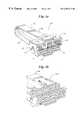
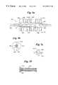
- FIG. 1 ais a perspective view of an inventive stent crimper
- FIG. 1 bis a perspective view of a portion of the crimper of FIG. 1 a;
- FIG. 2shows a crimping die
- FIG. 3 ais a perspective view of an inventive stent crimper in an open position
- FIG. 3 bis a perspective view of the inventive stent crimper of FIG. 3 a in a closed position
- FIG. 3 cis side elevational view of a crimping die
- FIG. 4is a schematic of an inventive stent crimper comprising two sets of opposing crimping dies
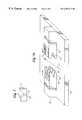
- FIG. 5 ais a perspective view of an inventive stent crimper
- FIG. 5 bis a perspective view showing the dies used in the inventive stent crimper shown in FIG. 5 a;
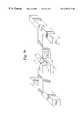
- FIG. 6is a front view of another embodiment of the invention.
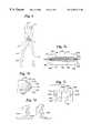
- FIG. 7 ais a side view of a crimping die for preventing stent flaring
- FIG. 7 bis a perspective view of an arrangement of crimping dies
- FIG. 7 cis a front view of an arrangement of crimping dies
- FIG. 7 dis a perspective view of an arrangement of crimping dies
- FIG. 8is a side view of a crimping die for achieving a non-uniform crimping of a stent
- FIG. 9 ashows another embodiment of the invention.
- FIG. 9 bshows a cross-section of FIG. 9 a taken along line 9 b — 9 b;
- FIG. 9 cshows a cross-section of an angled die
- FIG. 10shows a sleeve suitable for enclosing a stent when crimping it in the practice of the invention.
- stentrefers to stents, stent-grafts, grafts and other endoluminal prostheses whether self-expanding, balloon expandable or a combination of self-expanding and balloon expandable, as are known in the art.
- crimping a stentthe invention specifically contemplates crimping stents, stent-grafts, grafts and other endoluminal prostheses.
- the term ‘stent bearing region of a catheter’ and similar termsrefers to the portion of a catheter about which the stent is to be mounted where no balloon is used to expand the stent and, in the case of balloon expandable stents, refers to the portion of the catheter and balloon about which the stent is to be mounted.
- the term ‘crimp’ and its cognatesshall refer to reducing in size of a stent whether or not the stent is mounted on a catheter. In the later case, the crimping may also result in the stent being conformed, at least in part, to the shape of the catheter or any device mounted between the catheter and the stent.
- the present inventionis directed generally to an apparatus such as the one shown at 100 in FIG. 1 a, for reducing a medical device in size.
- the apparatuscomprises a plurality of first crimping dies 104 , a plurality of second crimping dies 116 and a crimping die moving device 132 connecting first crimping dies 104 and second crimping dies 116 .
- First crimping dies 104are linearly spaced along a first crimping member 130 which is mounted on crimping die moving device 132 .
- Second crimping dies 116are similarly aligned on a second crimping member 131 which is mounted on crimping die moving device 132 .
- Each first crimping die 104 and second die 116has a notch 108 therein forming a crimping surface 109 .
- Notch 108is substantially V-shaped.
- the base 112 of the V-shaped notchis desirably arcuate and more desirably, semicircular to accommodate a medical device such as a stent or the like therein.
- Notches 108 in first crimping dies 104are aligned so as to be capable of receiving a medical device therein as are notches 108 in second crimping dies 116 .
- First and second crimping dies 104 , 116are linearly displaced from one another along the length of the crimping members so as to mesh with one another when the crimper is closed. As shown in FIG. 1 a, first and second crimping dies 104 and 116 interleave with one another as the crimper is closed.
- First crimping member 130 and second crimping member 131extend from crimping die moving device 132 .
- crimping die moving device 132consists of a first arm 136 and a second arm 140 which are constructed from a single piece of material bent over on itself. Desirably, the first and second arms will have grooves 144 therein, as shown in FIG. 1 b, so that first and second crimping dies 104 and 116 may snap into place on first and second arms 136 and 140 , respectively.
- first and second crimping dies 104 and 116may snap into place on first and second arms 136 and 140 , respectively.
- first arm 136is shown with first crimping dies 104 and first crimping member 130 already in place whereas second arm 140 is shown without second crimping die 116 and second crimping member 131 for the sake of illustrating grooves 144 .
- Other suitable means of mounting the crimping dies and crimping membermay be used as well.
- first and second armsbeing formed of separate pieces of material which are then joined together through any suitable technique including bonding, adhesive or otherwise and welding.
- the two armsare desirably joined at their ends but the junction between the two arms may also be located elsewhere along the arms.
- the crimping die moving deviceas shown in FIG. 1 a, will be constructed of a resilient metal or plastic such that the apparatus will spring back to its open position where it will remain when released from the closed position.
- first crimping dies 104 and second crimping dies 116are slidingly mounted on abase 148 .
- First crimping dies 104extend from first crimping member 130 and second crimping dies 116 extend from second crimping member 131 .
- the crimping member and corresponding crimping diemay be of single piece or they may be made separately and joined together.
- each of the first crimping dies 104 and the second crimping dies 116have a notch therein.
- notch 116will have an arcuate or semicircular portion similar to that shown in FIG. 2 .
- First crimping dies 104 and second crimping dies 116are longitudinally displaced from one another so that the dies will mesh when as the crimper is closed, as shown in FIG. 4 b.
- base 148has a groove 135 cut therein which slidingly receives rail 137 which extends from each of first crimping die moving member 130 and second crimping device moving member 131 .
- rail 137which extends from each of first crimping die moving member 130 and second crimping device moving member 131 .
- a stent or other suitable medical deviceis inserted in the space between the first and second crimping dies and the dies slid together to reduce the diameter of the stent or other suitable device.
- the opening between the first dies 104 and the second dies 116designated by reference numeral 152 , is reduced in size, as illustrated in FIG. 3 b.
- a stent or other medical devicewhether by itself or disposed about a catheter will rest in opening 152 .
- an apparatus similar to that shown in FIG. 3 amay be constructed in which only one of the sets of crimping dies is slidable.
- a stentis disposed between the crimping dies and the slidable crimping dies slid toward the fixed crimping dies to reduce the diameter of the stent.
- the crimper of FIGS. 1 and 3is a self-centering crimper. Stents inserted between the notches in the first and second dies will self-center in the notches upon closure of the dies.
- FIG. 4is a schematic drawing of an embodiment in which four sets of crimping dies are provided.
- First and second crimping dies 114 and 116are disposed opposite one another and longitudinally displaced from one another as are third and fourth crimping dies 118 and 122 , moreover, third and fourth crimping dies 118 and 122 are rotated 90° with it to the first and second crimping dies.
- Stent 156is shown disposed about catheter 160 in opening 152 . Additional sets of crimping dies disposed at other angles may also be provided.
- the sets of crimping dieswill be arranged such that in the closed position they are regularly disposed about the opening between them. As shown in FIG. 4, the crimping dies are regularly disposed abut a common point 164 . Depending on the form of the dies, the dies may be interleaved or directly opposite one another.
- the sets of opposing diesmay be applied simultaneously or sequentially.
- the third and fourth die setsmay be closed and released after the first and second die sets have been utilized and removed thereby ensuring that each die set is able to contact and crimp the stent as desired regardless of the spacing of the dies.
- the inventioncontemplates embodiments having an even number of sets of crimping dies as well as embodiments having an odd number of crimping dies. In the latter case, none of the sets of crimping dies need be opposite one another.
- the inventive apparatuscomprises a single first crimping die 104 and a single second crimping die 116 as shown generally at 100 in FIGS. 5 a and 5 b.
- first and second crimping dies 104 and 116will be at least as long as the stent or other medical device to be crimped.
- First and second crimping dies 104 and 116extend from first and second crimping members 130 and 131 respectively.
- First and second crimping dies 104 and 116are longitudinally aligned in that the dies are not linearly displaced along the longitudinal axis 101 of the crimping device.
- First crimping member 130 and second crimping member 131each include an optional opening therein 150 to receive a device, such as an air cylinder or a pneumatic screw, shown schematically at 151 in FIG. 5 a, which is capable of moving the crimping members inward and outward.
- a devicesuch as an air cylinder or a pneumatic screw, shown schematically at 151 in FIG. 5 a, which is capable of moving the crimping members inward and outward.
- the diesmay also be hand operated.
- first and second dies 104 and 116rest upon base 148 .
- Base 148includes four raised portions 156 which form a cradle for first and second dies 104 and 116 .
- Raised portions 156also include a channel 160 in which a catheter may reside.
- the inventive crimperincludes a first crimping die 204 , a second crimping die 216 and a crimping die moving device 232 connecting first crimping die 204 and second crimping die 216 .
- Crimping die moving device 232includes first arm 236 and second arm 240 which are pivotally interconnected by fastener 241 .
- First and second crimping dies 204 and 216each have an arcuate or semicircular notch 208 therein. Notch 208 is sized to hold a stent therein.
- Crimping dies 204 and 216may be adhesively bonded or otherwise attached to arms 236 and 240 or formed integrally with the arms.
- the crimping membersmay also be removably attached to arms 236 and 240 for ease of changing members based on the specific crimping needs.
- a stent or other suitable medical deviceis inserted between first crimping die 204 and second crimping die 216 and first arm 236 and second arm 240 are moved relatively closer together. An inward force is thus applied to the stent or other medical device. The arms may then be moved apart to facilitate removal of the stent.
- the present applicationis also directed to stent crimpers capable of non-uniformly crimping a stent on a catheter and methods of non-uniformly crimping a stent to a catheter.
- Additional crimping of the end portionsprovides for an increased stent securement force relative to a crimped stent with a continuous inner and outer diameter profile.
- the additional crimpingalso provides atraumatic proximal and distal stent edges for advancement and withdrawal of the stent through delivery guides and vasculature thus reducing the likelihood that the stent will snag on the interior of a vessel or delivery guide. Any of the devices described above can be modified simply in order to apply the additional crimping force to the stent in the desired regions of the stent.
- a suitable crimping die for crimping the proximal and distal ends of a stent relative to the remainder of the stent to avoid flaring of the stent ends upon expansion of the stentis shown at 304 and 316 in FIG. 7 a.
- ends 356 a and 356 b of stent 356are reduced to a smaller diameter than intermediate portion 356 c.
- Dies 304 and 316may be used in conjunction with the crimping die moving device 232 shown in FIG. 6 or other suitable crimping die moving devices disclosed herein.
- a non-uniform crimpmay also be realized using devices such as those shown in FIGS. 1, 3 a, b, and 4 by providing an array of first crimping dies and an array of second crimping dies, each array including at least one crimping die at each end which, when taken along with the opposing die, defines a smaller diameter opening.
- Non-uniform diesmay also be useful in crimping a stent to a catheter which has suitable mounting devices extending therefrom.
- catheter 334has two stent support bands 343 mounted thereon.
- Stent 356has been crimped using dies 304 and 316 .
- the shape of dies 304 and 316conforms to the profile of catheter 334 and stent support bands 343 .
- Stent 356having been crimped by dies 304 and 316 , conforms to the catheter and support bands.
- FIG. 7 amay also be realized by mounting dies 304 and 316 in a manner similar to that shown in FIG. 5 a.
- the inventive conceptmay also be realized by providing a plurality of first and second crimping dies as in FIGS. 1, 3 a, 3 b and 4 which define suitable openings therebetween along the length of the stent.
- FIG. 7 bshows an arrangement of individual crimping dies 104 a-e, each having a crimping surface 109 a-e in the form of a V-shaped notch. The V-shaped notch grows progressively smaller from die 104 a to die 104 e.
- FIG. 7 cshows a front view of an arrangement of dies 104 a-d with notches 109 a-d that grow progressively deeper from sides 103 a,b of the arrangement to center 103 c of the arrangement.
- FIG. 7 dshows a perspective view of two of the dies of FIG. 7 c. It is, of course, understood that two such sets of opposing, interleaved dies are necessary to form the inventive stent crimper.
- movement of the diesmay be controlled by actuators which are arranged so as to output a desired force.
- the force applied to the various diemay differ depending on the location of the die.
- the stent crimpershown generally at 400 , comprises at least one die set, shown generally at 402 and desirably a plurality of side-by-side dies sets which define an opening for receiving a stent therein.
- Die sets 402includes a plurality of individual dies 404 . As shown in FIG. 9 b, each die 404 has an annular inner surface 405 .
- the inventionmay also be practiced using die sets which comprise two dies or die sets which comprise four or more individual dies. Dies 404 in a given die set 402 form an annulus when they are completely closed.
- Each die setis individually controlled by an actuation device which controls how much force is applied to the dies in a given die set. As soon as a desired force is achieved, the die is held in position until the desired force is achieved for the remaining dies, at which point the dies are released.
- the actuation devicemay include air cylinders or pneumatic screws and a suitable control system. Other commercially available actuation systems may be used as well. Desirably, the actuators will be set so that each of the individual dies applies equal pressure to the stent
- first dies 404 aare longer than second dies 404 b.
- the length of second dies 404 bcorresponds to the length of stent securement hubs 458 on catheter 460 underneath stent 456 .
- Stent 456shown in FIG. 9 a, has already been crimped in accordance with the invention to balloon 459 and catheter 460 .
- the inventive stent crimpermay further comprise angled dies at the ends, such as die 404 c, shown in cross section in FIG. 9 c, to reduce flaring of the stent ends.
- the inventionis further directed to methods of crimping a stent or other medical device using the inventive apparatuses disclosed herein.
- a stent or other medical deviceis disposed between the crimping dies of the apparatuses disclosed herein.
- the first and second crimping diesare then moved relatively closer together such that an inward force is applied to the medical device thereby reducing the medical device in size.
- the methodmay be used to crimp a stent uniformly or non-uniformly. An example of the latter is shown in FIG. 8 .
- Stent 356is crimped to a non-uniform diameter along its length. Ends 356 a,b are tapered.
- Middle portion 356 c and intermediate portions 356 d,eare crimped to different diameters (or, in the case of a stent with a substantially non-circular transverse cross-section, to different transverse cross-sectional areas).
- the stent or medical devicemay simply be reduced in size via the inventive method or may be crimped onto a catheter using the inventive method.
- a first crimping forceis applied to some of the crimping dies in the above inventive apparatuses and a second and different crimping force is applied to some other of the dies to facilitate crimping.
- the application of different forces to different diesis particularly useful in crimping a stent to a catheter having stent securement hubs or other non-uniformities in the catheter surface.
- the stentmay further be protected by a sleeve to prevent direct contact between the stent and the crimping device. This may minimize or eliminate any marring or nicking of the stent by the crimping member.
- the sleeveis comprised of elastomeric tubing, although more generally, polymeric tubing may be used.
- the sleevemay also be formed of a braided material.
- a sleevewhich has a full diameter and at least one reduced diameter configuration when a tension is applied to the sleeve may be used to protect the stent and to supply an additional crimping force to the stent.
- a preferred embodiment of a protective sleeve formed of braided materialis indicated at 500 in FIG. 10 .
- polymeric or metal braidsmay be used.
- Individual strands 503 of a given polymerare interwoven as shown in FIG. 10 to form tubular braid 500 .
- the weavemust be dense enough as to prevent parts of the stent, depending on the design of the stent, from penetrating the weave and becoming enmeshed in it.
- individual strands 503are made of Nylon having a circular cross section of diameter ⁇ fraction (5/1000) ⁇ inch.
- Strands 503are woven together in a clothing weave to form tubular braid 500 with the weave being about 20 to about 90 picks/inch, desirably about 55 picks/inch.
- An example of a braid tube braid tubeis one manufactured by SCIMED Life Systems, Inc., Maple Grove, Minn. and/or SantaFe Textiles, Inc., Los Angeles, Calif. Suitable ones may be manufactured by any other coil braider.
- Nylon or polypropylene propylenemay also be used for the braid as well as other suitable polymeric materials including elastomeric materials.
- the sleevemay also be provided in the form of a smooth polymeric tube.
- the protective sleevemay also be used to reduce the stent in size prior to the stent being crimped. By stretching the sleeve a radially inward may be applied to the stent.
- a typical crimping sequence that includes the use of the protective sleeveincludes the following steps:
- the rotating, sliding and crimping stepsmay be repeated, as necessary, until a desired final configuration is reached.
- Additional crimping stepsmay be applied to the stent following the above sequence.
- the inventionis further directed to methods of crimping in which any of the individual crimping modalities disclosed herein is combined in sequence with any other crimping modality disclosed herein and/or with any of the crimping modalities described in the commonly assigned, cofiled U.S. patent application Ser. Nos. 09/401,467, 09/404,986, and 09/401,218, and commonly assigned and copending U.S. application Ser. No. 08/951,550 all of which are directed to stent crimpers and all of which are incorporated herein in their entirety by reference.
- a stentmay be pre-crimped using one crimping technique and further crimped using another crimping technique.
Landscapes
- Health & Medical Sciences (AREA)
- Engineering & Computer Science (AREA)
- Biomedical Technology (AREA)
- Cardiology (AREA)
- Oral & Maxillofacial Surgery (AREA)
- Transplantation (AREA)
- Heart & Thoracic Surgery (AREA)
- Vascular Medicine (AREA)
- Life Sciences & Earth Sciences (AREA)
- Animal Behavior & Ethology (AREA)
- General Health & Medical Sciences (AREA)
- Public Health (AREA)
- Veterinary Medicine (AREA)
- Mechanical Engineering (AREA)
- Media Introduction/Drainage Providing Device (AREA)
Abstract
Description
Claims (18)
Priority Applications (2)
| Application Number | Priority Date | Filing Date | Title |
|---|---|---|---|
| US09/401,213US6387117B1 (en) | 1999-09-22 | 1999-09-22 | Stent crimping system |
| PCT/US2000/040583WO2001021076A1 (en) | 1999-09-22 | 2000-08-07 | Stent crimping system |
Applications Claiming Priority (1)
| Application Number | Priority Date | Filing Date | Title |
|---|---|---|---|
| US09/401,213US6387117B1 (en) | 1999-09-22 | 1999-09-22 | Stent crimping system |
Publications (1)
| Publication Number | Publication Date |
|---|---|
| US6387117B1true US6387117B1 (en) | 2002-05-14 |
Family
ID=23586834
Family Applications (1)
| Application Number | Title | Priority Date | Filing Date |
|---|---|---|---|
| US09/401,213Expired - LifetimeUS6387117B1 (en) | 1999-09-22 | 1999-09-22 | Stent crimping system |
Country Status (2)
| Country | Link |
|---|---|
| US (1) | US6387117B1 (en) |
| WO (1) | WO2001021076A1 (en) |
Cited By (61)
| Publication number | Priority date | Publication date | Assignee | Title |
|---|---|---|---|---|
| US6584821B1 (en)* | 2002-04-16 | 2003-07-01 | General Motors Company | Self-aligning non-pinching hydroforming dies |
| US20030135970A1 (en)* | 2000-11-16 | 2003-07-24 | Scimed Life Systems, Inc. | Bare stent ship and crimp device |
| US6607227B1 (en)* | 2000-06-28 | 2003-08-19 | Siemens Automotive Corporation | Sawtooth terminal blade gripper and method of gripping |
| US20040123437A1 (en)* | 2002-12-26 | 2004-07-01 | Arkady Kokish | Assembly for crimping an intraluminal device and method of use |
| US6802846B2 (en) | 2001-02-12 | 2004-10-12 | Ams Research Corporation | Foreign body retrieval device and method |
| US6823576B2 (en)* | 1999-09-22 | 2004-11-30 | Scimed Life Systems, Inc. | Method and apparatus for contracting, loading or crimping self-expanding and balloon expandable stent devices |
| US20050154450A1 (en)* | 2004-01-12 | 2005-07-14 | Karen Larson | Stent reducing system and device |
| US20050166389A1 (en)* | 2004-01-29 | 2005-08-04 | Scimed Life Systems, Inc. | Apparatuses for crimping and loading of intraluminal medical devices |
| US20050183259A1 (en)* | 2004-02-23 | 2005-08-25 | Tracee Eidenschink | Apparatus and method for crimping a stent assembly |
| US20050192498A1 (en)* | 2004-03-01 | 2005-09-01 | Scimed Life Systems, Inc. | Automated marker band nest placement crimper |
| US20050188525A1 (en)* | 2004-02-26 | 2005-09-01 | Scimed Life Systems, Inc. | Crimper |
| US20050229670A1 (en)* | 2004-04-16 | 2005-10-20 | Scimed Life Systems, Inc. | Stent crimper |
| US20050234537A1 (en)* | 2004-04-16 | 2005-10-20 | Scimed Life Systems, Inc. | Stent crimper |
| US20060036310A1 (en)* | 2004-08-13 | 2006-02-16 | Scimed Life Systems, Inc. | Method to simultaneously load and cover self expanding stents |
| US7096554B2 (en) | 2003-04-04 | 2006-08-29 | Boston Scientific Scimed, Inc. | Protective loading of stents |
| US20060213049A1 (en)* | 2005-03-23 | 2006-09-28 | Serrano Gabriel S | Stent crimping mechanisms |
| US20060288561A1 (en)* | 2005-06-27 | 2006-12-28 | Boston Scientific Scimed, Inc. | Crimping and edge protection elements |
| US20070056346A1 (en)* | 2005-09-09 | 2007-03-15 | Benjamin Spenser | Prosthetic valve crimping device |
| US20070199360A1 (en)* | 2005-11-17 | 2007-08-30 | The Cleveland Clinic Foundation | Method and apparatus for compressing intraluminal prostheses |
| US20070265694A1 (en)* | 2005-11-17 | 2007-11-15 | The Cleveland Clinic Foundation | Apparatus and method for delivering lined intraluminal prostheses |
| US20080001328A1 (en)* | 2006-06-30 | 2008-01-03 | Kent Darrin J | Stent retention mold and method |
| US20080127707A1 (en)* | 2006-11-30 | 2008-06-05 | Abbott Laboratories | Stent crimping assembly and method |
| US7389670B1 (en) | 2004-07-26 | 2008-06-24 | Abbott Laboratories | Stent crimping system |
| US20080262603A1 (en)* | 2007-04-23 | 2008-10-23 | Sorin Biomedica Cardio | Prosthetic heart valve holder |
| EP2014257A1 (en) | 2007-07-12 | 2009-01-14 | Sorin Biomedica Cardio S.R.L. | Expandable prosthetic valve crimping device |
| US20090018570A1 (en)* | 2007-07-12 | 2009-01-15 | Sorin Biomedica Cardio S.R.L. | Expandable prosthetic valve crimping device |
| US20090024088A1 (en)* | 2007-07-18 | 2009-01-22 | Boston Scientific Scimed, Inc. | Bifurcated Balloon Folding Method and Apparatus |
| US20090113693A1 (en)* | 2007-11-05 | 2009-05-07 | Cook Incorporated | Apparatus and method for compressing a stent |
| US20090131920A1 (en)* | 2007-11-16 | 2009-05-21 | Abbott Laboratories Vascular Enterprises Limited | Stent crimping apparatus |
| US20090264897A1 (en)* | 2008-03-18 | 2009-10-22 | Wohl Daniel L | Tonsil forceps |
| US20090299453A1 (en)* | 2008-05-30 | 2009-12-03 | Boston Scientific Scimed, Inc. | Stent crimping device |
| US7658880B2 (en) | 2005-07-29 | 2010-02-09 | Advanced Cardiovascular Systems, Inc. | Polymeric stent polishing method and apparatus |
| US20100057182A1 (en)* | 2008-08-02 | 2010-03-04 | Kevin Pilz | Method and device for loading a stent applicator |
| US7708548B2 (en)* | 2005-04-12 | 2010-05-04 | Advanced Cardiovascular Systems, Inc. | Molds for fabricating stents with profiles for gripping a balloon catheter |
| US20100185207A1 (en)* | 2009-01-20 | 2010-07-22 | Abbott Laboratories Vascular Enterprises Limited | Stent crimping device |
| US20100249661A1 (en)* | 2009-03-19 | 2010-09-30 | Sorin Biomedica Cardio S.r.I | Universal Valve Annulus Sizing Device |
| US20100262043A1 (en)* | 2009-03-26 | 2010-10-14 | Sorin Group Usa, Inc. | Annuloplasty sizers for minimally invasive procedures |
| US20110167764A1 (en)* | 2008-10-08 | 2011-07-14 | Dorn Juergen | Method of transferring a stent device from a crimping head to an outer sheath of a stent device delivery system |
| US8333003B2 (en) | 2008-05-19 | 2012-12-18 | Boston Scientific Scimed, Inc. | Bifurcation stent crimping systems and methods |
| US8652193B2 (en) | 2005-05-09 | 2014-02-18 | Angiomed Gmbh & Co. Medizintechnik Kg | Implant delivery device |
| WO2014026555A1 (en)* | 2012-08-14 | 2014-02-20 | 杭州启明医疗器械有限公司 | Compression device for artificial valve replacing device |
| US20150107078A1 (en)* | 2013-10-23 | 2015-04-23 | Biotronik Ag | Method for fitting an implant to a catheter |
| US9161836B2 (en) | 2011-02-14 | 2015-10-20 | Sorin Group Italia S.R.L. | Sutureless anchoring device for cardiac valve prostheses |
| US9248017B2 (en) | 2010-05-21 | 2016-02-02 | Sorin Group Italia S.R.L. | Support device for valve prostheses and corresponding kit |
| US9289289B2 (en) | 2011-02-14 | 2016-03-22 | Sorin Group Italia S.R.L. | Sutureless anchoring device for cardiac valve prostheses |
| US9486313B2 (en) | 2005-02-10 | 2016-11-08 | Sorin Group Italia S.R.L. | Cardiac valve prosthesis |
| US9757232B2 (en) | 2014-05-22 | 2017-09-12 | Edwards Lifesciences Corporation | Crimping apparatus for crimping prosthetic valve with protruding anchors |
| US9848981B2 (en) | 2007-10-12 | 2017-12-26 | Mayo Foundation For Medical Education And Research | Expandable valve prosthesis with sealing mechanism |
| US9867695B2 (en) | 2004-03-03 | 2018-01-16 | Sorin Group Italia S.R.L. | Minimally-invasive cardiac-valve prosthesis |
| US10010412B2 (en) | 2011-07-27 | 2018-07-03 | Edwards Lifesciences Corporation | Conical crimper |
| US10098733B2 (en) | 2008-12-23 | 2018-10-16 | Sorin Group Italia S.R.L. | Expandable prosthetic valve having anchoring appendages |
| US10639147B2 (en) | 2016-06-24 | 2020-05-05 | Edwards Lifesciences Corporation | System and method for crimping a prosthetic valve |
| US10716691B2 (en) | 2016-06-24 | 2020-07-21 | Edwards Lifesciences Corporation | Compact crimping device |
| US11504231B2 (en) | 2018-05-23 | 2022-11-22 | Corcym S.R.L. | Cardiac valve prosthesis |
| US11819406B2 (en) | 2018-05-23 | 2023-11-21 | Corcym S.R.L. | Loading system for an implantable prosthesis and related loading method |
| US11944559B2 (en) | 2020-08-31 | 2024-04-02 | Edwards Lifesciences Corporation | Systems and methods for crimping and device preparation |
| US11992397B2 (en) | 2018-05-23 | 2024-05-28 | Corcym S.R.L. | Holder for heart valve prosthesis, a storage arrangement for a heart valve prosthesis, and a crimping kit and method |
| US20240216139A1 (en)* | 2020-06-18 | 2024-07-04 | Edwards Lifesciences Corporation | Crimping devices and methods |
| US12083013B2 (en) | 2017-10-07 | 2024-09-10 | Corcym S.R.L. | Bendable cardiac surgery instruments |
| US12318289B2 (en) | 2018-05-23 | 2025-06-03 | Corcym S.R.L. | Device for the in-situ delivery of heart valve prosthesis |
| US12357456B2 (en) | 2018-04-30 | 2025-07-15 | Edwards Lifesciences Corporation | Devices and methods for crimping prosthetic implants |
Families Citing this family (5)
| Publication number | Priority date | Publication date | Assignee | Title |
|---|---|---|---|---|
| EP1179322A3 (en)* | 2000-08-09 | 2004-02-25 | BIOTRONIK Mess- und Therapiegeräte GmbH & Co Ingenieurbüro Berlin | Stent crimping method and device |
| US6702845B1 (en)* | 2003-01-17 | 2004-03-09 | Gore Enterprise Holdings, Inc. | Compacted implantable medical devices and method of compacting such devices |
| CN110226995B (en)* | 2019-06-06 | 2020-04-10 | 高峰 | Accurate positioning device for aorta tectorial membrane stent |
| WO2021194976A1 (en) | 2020-03-26 | 2021-09-30 | Medtronic, Inc. | Clamshell iris-style crimper for medical devices |
| US11844713B2 (en)* | 2020-08-06 | 2023-12-19 | Medtronic, Inc. | Iris-style crimpers for medical devices |
Citations (34)
| Publication number | Priority date | Publication date | Assignee | Title |
|---|---|---|---|---|
| US2948171A (en)* | 1958-10-02 | 1960-08-09 | Louis V Lucibello | Tool for adjusting the snap-action of a leaf-type operating device |
| US5026377A (en) | 1989-07-13 | 1991-06-25 | American Medical Systems, Inc. | Stent placement instrument and method |
| US5138864A (en)* | 1990-12-28 | 1992-08-18 | Ripley Company, Inc. | Crimping tool |
| US5183085A (en) | 1991-09-27 | 1993-02-02 | Hans Timmermans | Method and apparatus for compressing a stent prior to insertion |
| US5290305A (en) | 1991-10-11 | 1994-03-01 | Kanji Inoue | Appliance collapsible for insertion into human organs and capable of resilient restoration |
| EP0630623A2 (en) | 1993-05-24 | 1994-12-28 | Advanced Cardiovascular Systems, Inc. | Mechanism for loading a stent on a catheter |
| US5381686A (en) | 1994-03-03 | 1995-01-17 | Coherent Inc. | Dual-action pneumo-hydraulic crimping apparatus |
| US5411521A (en) | 1992-03-04 | 1995-05-02 | American Cyanamid Company | Medical suturing device, a single-strike die mechanism, and a method of using said die mechanism for forming the medical suturing device |
| DE29506654U1 (en) | 1995-04-19 | 1995-06-08 | Hurtado Artozon, Roberto, Dr.med., 46047 Oberhausen | Spreader for stents |
| WO1996003092A1 (en) | 1994-07-28 | 1996-02-08 | Brun, Heidi, M. | A flexible expandable stent |
| EP0701800A1 (en) | 1994-09-15 | 1996-03-20 | C.R. Bard, Inc. | Method and apparatus for recapture of hooked endoprosthesis |
| US5509184A (en) | 1993-02-19 | 1996-04-23 | Trouvay & Cauvin S.A. | Apparatus for crimping a tube in a thick panel |
| US5591222A (en) | 1991-10-18 | 1997-01-07 | Susawa; Takashi | Method of manufacturing a device to dilate ducts in vivo |
| DE19532288A1 (en) | 1995-09-01 | 1997-03-06 | Ulrich Dipl Phys Dr M Solzbach | Aid for applying stent on balloon of dilation catheter |
| US5626604A (en) | 1995-12-05 | 1997-05-06 | Cordis Corporation | Hand held stent crimping device |
| US5628754A (en) | 1995-08-01 | 1997-05-13 | Medtronic, Inc. | Stent delivery guide catheter |
| US5630830A (en) | 1996-04-10 | 1997-05-20 | Medtronic, Inc. | Device and method for mounting stents on delivery systems |
| WO1997020593A1 (en) | 1995-12-04 | 1997-06-12 | Cordis Corporation | Stent compression instrument |
| US5672169A (en) | 1996-04-10 | 1997-09-30 | Medtronic, Inc. | Stent mounting device |
| US5692294A (en)* | 1995-06-09 | 1997-12-02 | The Whitaker Corporation | Tools for crimping an electrical contact onto a conductor |
| US5700285A (en) | 1993-08-18 | 1997-12-23 | W. L. Gore & Associates, Inc. | Intraluminal stent graft |
| US5725519A (en) | 1996-09-30 | 1998-03-10 | Medtronic Instent Israel Ltd. | Stent loading device for a balloon catheter |
| US5732530A (en)* | 1995-11-20 | 1998-03-31 | Pfaff; Kathleen Sue | Method of sealing a balloon after it is inflated |
| US5749921A (en) | 1996-02-20 | 1998-05-12 | Medtronic, Inc. | Apparatus and methods for compression of endoluminal prostheses |
| WO1998019633A1 (en) | 1996-11-06 | 1998-05-14 | Percusurge, Inc. | Apparatus and method for loading a stent on a catheter |
| US5766203A (en) | 1995-07-20 | 1998-06-16 | Intelliwire, Inc. | Sheath with expandable distal extremity and balloon catheters and stents for use therewith and method |
| US5810871A (en) | 1997-04-29 | 1998-09-22 | Medtronic, Inc. | Stent delivery system |
| US5810873A (en) | 1997-07-15 | 1998-09-22 | Advanced Cardiovascular Systems, Inc. | Stent crimping tool and method of use |
| US5836952A (en) | 1996-08-21 | 1998-11-17 | Cordis Corporation | Hand-held stent crimper |
| US5836965A (en) | 1994-10-19 | 1998-11-17 | Jendersee; Brad | Stent delivery and deployment method |
| US5860966A (en) | 1997-04-16 | 1999-01-19 | Numed, Inc. | Method of securing a stent on a balloon catheter |
| US5893852A (en) | 1998-04-28 | 1999-04-13 | Advanced Cardiovascular Systems, Inc. | Stent crimping tool and method of use |
| US5911752A (en) | 1996-09-13 | 1999-06-15 | Intratherapeutics, Inc. | Method for collapsing a stent |
| US5992000A (en) | 1997-10-16 | 1999-11-30 | Scimed Life Systems, Inc. | Stent crimper |
- 1999
- 1999-09-22USUS09/401,213patent/US6387117B1/ennot_activeExpired - Lifetime
- 2000
- 2000-08-07WOPCT/US2000/040583patent/WO2001021076A1/enactiveApplication Filing
Patent Citations (39)
| Publication number | Priority date | Publication date | Assignee | Title |
|---|---|---|---|---|
| US2948171A (en)* | 1958-10-02 | 1960-08-09 | Louis V Lucibello | Tool for adjusting the snap-action of a leaf-type operating device |
| US5026377A (en) | 1989-07-13 | 1991-06-25 | American Medical Systems, Inc. | Stent placement instrument and method |
| US5138864A (en)* | 1990-12-28 | 1992-08-18 | Ripley Company, Inc. | Crimping tool |
| US5183085A (en) | 1991-09-27 | 1993-02-02 | Hans Timmermans | Method and apparatus for compressing a stent prior to insertion |
| US5290305A (en) | 1991-10-11 | 1994-03-01 | Kanji Inoue | Appliance collapsible for insertion into human organs and capable of resilient restoration |
| US5591222A (en) | 1991-10-18 | 1997-01-07 | Susawa; Takashi | Method of manufacturing a device to dilate ducts in vivo |
| US5411521A (en) | 1992-03-04 | 1995-05-02 | American Cyanamid Company | Medical suturing device, a single-strike die mechanism, and a method of using said die mechanism for forming the medical suturing device |
| US5509184A (en) | 1993-02-19 | 1996-04-23 | Trouvay & Cauvin S.A. | Apparatus for crimping a tube in a thick panel |
| US5738674A (en) | 1993-05-24 | 1998-04-14 | Advanced Cardiovascular Systems, Inc. | Stent loading mechanism |
| US5437083A (en) | 1993-05-24 | 1995-08-01 | Advanced Cardiovascular Systems, Inc. | Stent-loading mechanism |
| US5546646A (en) | 1993-05-24 | 1996-08-20 | Advanced Cardiovascular Systems, Inc. | Method for mounting an intravascular stent on a catheter |
| EP0630623A2 (en) | 1993-05-24 | 1994-12-28 | Advanced Cardiovascular Systems, Inc. | Mechanism for loading a stent on a catheter |
| US5700285A (en) | 1993-08-18 | 1997-12-23 | W. L. Gore & Associates, Inc. | Intraluminal stent graft |
| US5381686A (en) | 1994-03-03 | 1995-01-17 | Coherent Inc. | Dual-action pneumo-hydraulic crimping apparatus |
| WO1996003092A1 (en) | 1994-07-28 | 1996-02-08 | Brun, Heidi, M. | A flexible expandable stent |
| EP0701800A1 (en) | 1994-09-15 | 1996-03-20 | C.R. Bard, Inc. | Method and apparatus for recapture of hooked endoprosthesis |
| US5836965A (en) | 1994-10-19 | 1998-11-17 | Jendersee; Brad | Stent delivery and deployment method |
| DE29506654U1 (en) | 1995-04-19 | 1995-06-08 | Hurtado Artozon, Roberto, Dr.med., 46047 Oberhausen | Spreader for stents |
| US5692294A (en)* | 1995-06-09 | 1997-12-02 | The Whitaker Corporation | Tools for crimping an electrical contact onto a conductor |
| US5766203A (en) | 1995-07-20 | 1998-06-16 | Intelliwire, Inc. | Sheath with expandable distal extremity and balloon catheters and stents for use therewith and method |
| US5628754A (en) | 1995-08-01 | 1997-05-13 | Medtronic, Inc. | Stent delivery guide catheter |
| DE19532288A1 (en) | 1995-09-01 | 1997-03-06 | Ulrich Dipl Phys Dr M Solzbach | Aid for applying stent on balloon of dilation catheter |
| US5732530A (en)* | 1995-11-20 | 1998-03-31 | Pfaff; Kathleen Sue | Method of sealing a balloon after it is inflated |
| WO1997020593A1 (en) | 1995-12-04 | 1997-06-12 | Cordis Corporation | Stent compression instrument |
| US5746764A (en) | 1995-12-04 | 1998-05-05 | Atrion Medical Products, Inc. | Stent compression instrument |
| US5626604A (en) | 1995-12-05 | 1997-05-06 | Cordis Corporation | Hand held stent crimping device |
| US5749921A (en) | 1996-02-20 | 1998-05-12 | Medtronic, Inc. | Apparatus and methods for compression of endoluminal prostheses |
| US5672169A (en) | 1996-04-10 | 1997-09-30 | Medtronic, Inc. | Stent mounting device |
| US5630830A (en) | 1996-04-10 | 1997-05-20 | Medtronic, Inc. | Device and method for mounting stents on delivery systems |
| US5836952A (en) | 1996-08-21 | 1998-11-17 | Cordis Corporation | Hand-held stent crimper |
| US5911752A (en) | 1996-09-13 | 1999-06-15 | Intratherapeutics, Inc. | Method for collapsing a stent |
| US5725519A (en) | 1996-09-30 | 1998-03-10 | Medtronic Instent Israel Ltd. | Stent loading device for a balloon catheter |
| WO1998019633A1 (en) | 1996-11-06 | 1998-05-14 | Percusurge, Inc. | Apparatus and method for loading a stent on a catheter |
| US5893867A (en) | 1996-11-06 | 1999-04-13 | Percusurge, Inc. | Stent positioning apparatus and method |
| US5860966A (en) | 1997-04-16 | 1999-01-19 | Numed, Inc. | Method of securing a stent on a balloon catheter |
| US5810871A (en) | 1997-04-29 | 1998-09-22 | Medtronic, Inc. | Stent delivery system |
| US5810873A (en) | 1997-07-15 | 1998-09-22 | Advanced Cardiovascular Systems, Inc. | Stent crimping tool and method of use |
| US5992000A (en) | 1997-10-16 | 1999-11-30 | Scimed Life Systems, Inc. | Stent crimper |
| US5893852A (en) | 1998-04-28 | 1999-04-13 | Advanced Cardiovascular Systems, Inc. | Stent crimping tool and method of use |
Cited By (129)
| Publication number | Priority date | Publication date | Assignee | Title |
|---|---|---|---|---|
| US6823576B2 (en)* | 1999-09-22 | 2004-11-30 | Scimed Life Systems, Inc. | Method and apparatus for contracting, loading or crimping self-expanding and balloon expandable stent devices |
| US20040051330A1 (en)* | 2000-06-28 | 2004-03-18 | Siemens Automotive Corporation | Sawtooth terminal blade gripper and method of gripping |
| US7322623B2 (en) | 2000-06-28 | 2008-01-29 | Morton Gregory R | Sawtooth terminal blade gripper and method of gripping |
| US6607227B1 (en)* | 2000-06-28 | 2003-08-19 | Siemens Automotive Corporation | Sawtooth terminal blade gripper and method of gripping |
| US20030135970A1 (en)* | 2000-11-16 | 2003-07-24 | Scimed Life Systems, Inc. | Bare stent ship and crimp device |
| US6920674B2 (en) | 2000-11-16 | 2005-07-26 | Scimed Life Systems, Inc. | Bare stent ship and crimp device |
| US6802846B2 (en) | 2001-02-12 | 2004-10-12 | Ams Research Corporation | Foreign body retrieval device and method |
| US6584821B1 (en)* | 2002-04-16 | 2003-07-01 | General Motors Company | Self-aligning non-pinching hydroforming dies |
| US20040123437A1 (en)* | 2002-12-26 | 2004-07-01 | Arkady Kokish | Assembly for crimping an intraluminal device and method of use |
| US7152452B2 (en)* | 2002-12-26 | 2006-12-26 | Advanced Cardiovascular Systems, Inc. | Assembly for crimping an intraluminal device and method of use |
| US7096554B2 (en) | 2003-04-04 | 2006-08-29 | Boston Scientific Scimed, Inc. | Protective loading of stents |
| US20050154450A1 (en)* | 2004-01-12 | 2005-07-14 | Karen Larson | Stent reducing system and device |
| JP2007517587A (en)* | 2004-01-12 | 2007-07-05 | ボストン サイエンティフィック リミテッド | Stent reduction system |
| WO2005070335A1 (en)* | 2004-01-12 | 2005-08-04 | Boston Scientific Limited | Stent reducing system |
| US7284401B2 (en) | 2004-01-12 | 2007-10-23 | Boston Scientific Scimed, Inc. | Stent reducing system and device |
| US7926320B2 (en) | 2004-01-29 | 2011-04-19 | Boston Scientific Scimed, Inc. | Apparatuses for crimping and loading of intraluminal medical devices |
| US20110162432A1 (en)* | 2004-01-29 | 2011-07-07 | Boston Scientific Scimed, Inc. | Apparatuses for crimping and loading of intraluminal medical devices |
| US8438895B2 (en) | 2004-01-29 | 2013-05-14 | Boston Scientific Scimed, Inc. | Apparatuses for crimping and loading of intraluminal medical devices |
| US20080173061A1 (en)* | 2004-01-29 | 2008-07-24 | Boston Scientific Scimed, Inc. | Apparatuses for crimping and loading of intraluminal medical devices |
| US7636997B2 (en) | 2004-01-29 | 2009-12-29 | Boston Scientific Scimed, Inc. | Method for crimping and loading of intraluminal medical devices |
| US7316147B2 (en) | 2004-01-29 | 2008-01-08 | Boston Scientific Scimed, Inc. | Apparatuses for crimping and loading of intraluminal medical devices |
| US20100095513A1 (en)* | 2004-01-29 | 2010-04-22 | Boston Scientific Scimed, Inc. | Apparatuses for crimping and loading of intraluminal medical devices |
| US20050166389A1 (en)* | 2004-01-29 | 2005-08-04 | Scimed Life Systems, Inc. | Apparatuses for crimping and loading of intraluminal medical devices |
| WO2005082578A1 (en)* | 2004-02-23 | 2005-09-09 | Boston Scientific Limited | Apparatus and method for crimping a stent assembly |
| US7225518B2 (en) | 2004-02-23 | 2007-06-05 | Boston Scientific Scimed, Inc. | Apparatus for crimping a stent assembly |
| US20050183259A1 (en)* | 2004-02-23 | 2005-08-25 | Tracee Eidenschink | Apparatus and method for crimping a stent assembly |
| US20070193328A1 (en)* | 2004-02-26 | 2007-08-23 | Boston Scientific Scimed, Inc. | Crimper |
| US8516871B2 (en) | 2004-02-26 | 2013-08-27 | Boston Scientific Scimed, Inc. | Crimper |
| US7886569B2 (en) | 2004-02-26 | 2011-02-15 | Boston Scientific Scimed, Inc. | Crimper |
| US20050188525A1 (en)* | 2004-02-26 | 2005-09-01 | Scimed Life Systems, Inc. | Crimper |
| US20110100086A1 (en)* | 2004-02-26 | 2011-05-05 | Boston Scientific Scimed, Inc. | Crimper |
| WO2005092574A1 (en)* | 2004-02-26 | 2005-10-06 | Boston Scientific Limited | Crimper |
| US7578041B2 (en) | 2004-02-26 | 2009-08-25 | Boston Scientific Scimed, Inc. | Method of reducing a stent in cross-section |
| US7207204B2 (en) | 2004-02-26 | 2007-04-24 | Boston Scientific Scimed, Inc. | Crimper |
| US7480973B2 (en)* | 2004-03-01 | 2009-01-27 | Boston Scientific Scimed, Inc. | Automated marker band nest placement crimper |
| US20050192498A1 (en)* | 2004-03-01 | 2005-09-01 | Scimed Life Systems, Inc. | Automated marker band nest placement crimper |
| US9867695B2 (en) | 2004-03-03 | 2018-01-16 | Sorin Group Italia S.R.L. | Minimally-invasive cardiac-valve prosthesis |
| US7143625B2 (en)* | 2004-04-16 | 2006-12-05 | Boston Scientific Scimed, Inc. | Stent crimper |
| US20050234537A1 (en)* | 2004-04-16 | 2005-10-20 | Scimed Life Systems, Inc. | Stent crimper |
| US20050229670A1 (en)* | 2004-04-16 | 2005-10-20 | Scimed Life Systems, Inc. | Stent crimper |
| US7021114B2 (en) | 2004-04-16 | 2006-04-04 | Boston Scientific Scimed, Inc. | Stent crimper |
| US7389670B1 (en) | 2004-07-26 | 2008-06-24 | Abbott Laboratories | Stent crimping system |
| US8215149B1 (en) | 2004-07-26 | 2012-07-10 | Abbott Laboratories | Stent crimping system and method |
| US7628051B1 (en) | 2004-07-26 | 2009-12-08 | Abbott Laboratories | Stent crimping system |
| US7765670B2 (en)* | 2004-08-13 | 2010-08-03 | Boston Scientific Scimed, Inc. | Method to simultaneously load and cover self expanding stents |
| US20060036310A1 (en)* | 2004-08-13 | 2006-02-16 | Scimed Life Systems, Inc. | Method to simultaneously load and cover self expanding stents |
| US9895223B2 (en) | 2005-02-10 | 2018-02-20 | Sorin Group Italia S.R.L. | Cardiac valve prosthesis |
| US9486313B2 (en) | 2005-02-10 | 2016-11-08 | Sorin Group Italia S.R.L. | Cardiac valve prosthesis |
| US8104321B2 (en) | 2005-03-23 | 2012-01-31 | Boston Scientific Scimed, Inc. | Stent crimping mechanisms |
| US20060213049A1 (en)* | 2005-03-23 | 2006-09-28 | Serrano Gabriel S | Stent crimping mechanisms |
| US20100274342A1 (en)* | 2005-03-23 | 2010-10-28 | Boston Scientific Scimed, Inc. | Stent crimping mechanisms |
| US7748248B2 (en) | 2005-03-23 | 2010-07-06 | Boston Scientific Scimed, Inc. | Stent crimping mechanisms |
| US8393887B2 (en) | 2005-04-12 | 2013-03-12 | Advanced Cardiovascular Systems, Inc. | Stents with profiles for gripping a balloon catheter and molds for fabricating stents |
| US7708548B2 (en)* | 2005-04-12 | 2010-05-04 | Advanced Cardiovascular Systems, Inc. | Molds for fabricating stents with profiles for gripping a balloon catheter |
| US20100217378A1 (en)* | 2005-04-12 | 2010-08-26 | Daniel Gene Brown | Stents With Profiles For Gripping A Balloon Catheter And Molds For Fabricating Stents |
| US8652193B2 (en) | 2005-05-09 | 2014-02-18 | Angiomed Gmbh & Co. Medizintechnik Kg | Implant delivery device |
| US20060288561A1 (en)* | 2005-06-27 | 2006-12-28 | Boston Scientific Scimed, Inc. | Crimping and edge protection elements |
| US8099851B2 (en) | 2005-06-27 | 2012-01-24 | Boston Scientific Scimed, Inc. | Crimping and edge protection elements |
| US7658880B2 (en) | 2005-07-29 | 2010-02-09 | Advanced Cardiovascular Systems, Inc. | Polymeric stent polishing method and apparatus |
| US7530253B2 (en) | 2005-09-09 | 2009-05-12 | Edwards Lifesciences Corporation | Prosthetic valve crimping device |
| US20070056346A1 (en)* | 2005-09-09 | 2007-03-15 | Benjamin Spenser | Prosthetic valve crimping device |
| US20070265694A1 (en)* | 2005-11-17 | 2007-11-15 | The Cleveland Clinic Foundation | Apparatus and method for delivering lined intraluminal prostheses |
| US20070199360A1 (en)* | 2005-11-17 | 2007-08-30 | The Cleveland Clinic Foundation | Method and apparatus for compressing intraluminal prostheses |
| US8020275B2 (en) | 2005-11-17 | 2011-09-20 | The Cleveland Clinic Foundation | Method for compressing intraluminal prostheses |
| US8182522B2 (en) | 2005-11-17 | 2012-05-22 | The Cleveland Clinic Foundation | Apparatus and method for delivering lined intraluminal prostheses |
| US20080001328A1 (en)* | 2006-06-30 | 2008-01-03 | Kent Darrin J | Stent retention mold and method |
| US8240020B2 (en)* | 2006-06-30 | 2012-08-14 | Advanced Cardiovascular Systems, Inc. | Stent retention mold and method |
| US20080127707A1 (en)* | 2006-11-30 | 2008-06-05 | Abbott Laboratories | Stent crimping assembly and method |
| US20080262603A1 (en)* | 2007-04-23 | 2008-10-23 | Sorin Biomedica Cardio | Prosthetic heart valve holder |
| US8640521B2 (en) | 2007-07-12 | 2014-02-04 | Sorin Group Italia S.R.L. | Expandable prosthetic valve crimping device |
| EP2229921A1 (en) | 2007-07-12 | 2010-09-22 | Sorin Biomedica Cardio S.R.L. | Expandable prosthetic valve crimping device |
| US20090018570A1 (en)* | 2007-07-12 | 2009-01-15 | Sorin Biomedica Cardio S.R.L. | Expandable prosthetic valve crimping device |
| US8006535B2 (en) | 2007-07-12 | 2011-08-30 | Sorin Biomedica Cardio S.R.L. | Expandable prosthetic valve crimping device |
| EP2014257A1 (en) | 2007-07-12 | 2009-01-14 | Sorin Biomedica Cardio S.R.L. | Expandable prosthetic valve crimping device |
| US7942661B2 (en)* | 2007-07-18 | 2011-05-17 | Boston Scientific Scimed, Inc. | Bifurcated balloon folding method and apparatus |
| US20090024088A1 (en)* | 2007-07-18 | 2009-01-22 | Boston Scientific Scimed, Inc. | Bifurcated Balloon Folding Method and Apparatus |
| US10966823B2 (en) | 2007-10-12 | 2021-04-06 | Sorin Group Italia S.R.L. | Expandable valve prosthesis with sealing mechanism |
| US9848981B2 (en) | 2007-10-12 | 2017-12-26 | Mayo Foundation For Medical Education And Research | Expandable valve prosthesis with sealing mechanism |
| US20090113693A1 (en)* | 2007-11-05 | 2009-05-07 | Cook Incorporated | Apparatus and method for compressing a stent |
| US8256263B2 (en) | 2007-11-05 | 2012-09-04 | Cook Medical Technologies Llc | Apparatus and method for compressing a stent |
| US20090131920A1 (en)* | 2007-11-16 | 2009-05-21 | Abbott Laboratories Vascular Enterprises Limited | Stent crimping apparatus |
| US20090264897A1 (en)* | 2008-03-18 | 2009-10-22 | Wohl Daniel L | Tonsil forceps |
| US8333003B2 (en) | 2008-05-19 | 2012-12-18 | Boston Scientific Scimed, Inc. | Bifurcation stent crimping systems and methods |
| US20090299453A1 (en)* | 2008-05-30 | 2009-12-03 | Boston Scientific Scimed, Inc. | Stent crimping device |
| US8225474B2 (en) | 2008-05-30 | 2012-07-24 | Boston Scientific Scimed, Inc. | Stent crimping device |
| US20100057182A1 (en)* | 2008-08-02 | 2010-03-04 | Kevin Pilz | Method and device for loading a stent applicator |
| US10004623B2 (en) | 2008-10-08 | 2018-06-26 | C. R. Bard, Inc. | Stent device, a crimping head, and an outer sheath of a stent device delivery system |
| US20110167764A1 (en)* | 2008-10-08 | 2011-07-14 | Dorn Juergen | Method of transferring a stent device from a crimping head to an outer sheath of a stent device delivery system |
| US9089449B2 (en) | 2008-10-08 | 2015-07-28 | C. R. Bard, Inc. | Method of transferring a stent device from a crimping head to an outer sheath of a stent device delivery system |
| US9248036B2 (en) | 2008-10-08 | 2016-02-02 | C. R. Bard, Inc. | Method of transferring a stent device from a crimping head to an outer sheath of a stent device delivery system |
| US10098733B2 (en) | 2008-12-23 | 2018-10-16 | Sorin Group Italia S.R.L. | Expandable prosthetic valve having anchoring appendages |
| US8112857B2 (en) | 2009-01-20 | 2012-02-14 | Abbott Laboratories Vascular Enterprises Limited | Stent crimping device |
| US20100185207A1 (en)* | 2009-01-20 | 2010-07-22 | Abbott Laboratories Vascular Enterprises Limited | Stent crimping device |
| US8715207B2 (en) | 2009-03-19 | 2014-05-06 | Sorin Group Italia S.R.L. | Universal valve annulus sizing device |
| US9918841B2 (en) | 2009-03-19 | 2018-03-20 | Sorin Group Italia S.R.L. | Universal valve annulus sizing device |
| US20100249661A1 (en)* | 2009-03-19 | 2010-09-30 | Sorin Biomedica Cardio S.r.I | Universal Valve Annulus Sizing Device |
| US9149207B2 (en) | 2009-03-26 | 2015-10-06 | Sorin Group Usa, Inc. | Annuloplasty sizers for minimally invasive procedures |
| US20100262043A1 (en)* | 2009-03-26 | 2010-10-14 | Sorin Group Usa, Inc. | Annuloplasty sizers for minimally invasive procedures |
| US9248017B2 (en) | 2010-05-21 | 2016-02-02 | Sorin Group Italia S.R.L. | Support device for valve prostheses and corresponding kit |
| US9289289B2 (en) | 2011-02-14 | 2016-03-22 | Sorin Group Italia S.R.L. | Sutureless anchoring device for cardiac valve prostheses |
| US9161836B2 (en) | 2011-02-14 | 2015-10-20 | Sorin Group Italia S.R.L. | Sutureless anchoring device for cardiac valve prostheses |
| US10918478B2 (en) | 2011-07-27 | 2021-02-16 | Edwards Lifesciences Corporation | Crimping device |
| US11638644B2 (en) | 2011-07-27 | 2023-05-02 | Edwards Lifesciences Corporation | Crimping device |
| US10010412B2 (en) | 2011-07-27 | 2018-07-03 | Edwards Lifesciences Corporation | Conical crimper |
| RU2614497C2 (en)* | 2012-08-14 | 2017-03-28 | Винес Медтек (Ханчжоу), Инк. | Compression device for device represented by replacement artificial valve |
| JP2015524718A (en)* | 2012-08-14 | 2015-08-27 | 杭州啓明医療器械有限公司 | Compressor for artificial valve replacement device |
| WO2014026555A1 (en)* | 2012-08-14 | 2014-02-20 | 杭州启明医疗器械有限公司 | Compression device for artificial valve replacing device |
| US10098735B2 (en) | 2012-08-14 | 2018-10-16 | Venus Medtech (Hangzhou), Inc. | Compression device for artificial valve replacing device |
| US20150107078A1 (en)* | 2013-10-23 | 2015-04-23 | Biotronik Ag | Method for fitting an implant to a catheter |
| EP2865355A1 (en) | 2013-10-23 | 2015-04-29 | Biotronik AG | Method for fitting an implant to a catheter |
| US10182910B2 (en)* | 2013-10-23 | 2019-01-22 | Biotronik Ag | Method for fitting an implant to a catheter |
| US9757232B2 (en) | 2014-05-22 | 2017-09-12 | Edwards Lifesciences Corporation | Crimping apparatus for crimping prosthetic valve with protruding anchors |
| US10292819B2 (en) | 2014-05-22 | 2019-05-21 | Edwards Lifesciences Corporation | Crimping accessory devices and methods of use |
| US10716691B2 (en) | 2016-06-24 | 2020-07-21 | Edwards Lifesciences Corporation | Compact crimping device |
| US10639147B2 (en) | 2016-06-24 | 2020-05-05 | Edwards Lifesciences Corporation | System and method for crimping a prosthetic valve |
| US11344409B2 (en) | 2016-06-24 | 2022-05-31 | Edwards Lifesciences Corporation | System and method for crimping a prosthetic valve |
| US11510794B2 (en) | 2016-06-24 | 2022-11-29 | Edwards Lifesciences Corporation | Compact crimping device |
| US11523923B2 (en) | 2016-06-24 | 2022-12-13 | Edwards Lifesciences Corporation | Compact crimping device |
| US11951025B2 (en) | 2016-06-24 | 2024-04-09 | Edwards Lifesciences Corporation | Compact crimping device |
| US11833040B2 (en) | 2016-06-24 | 2023-12-05 | Edwards Lifesciences Corporation | System and method for crimping a prosthetic valve |
| US12083013B2 (en) | 2017-10-07 | 2024-09-10 | Corcym S.R.L. | Bendable cardiac surgery instruments |
| US12357456B2 (en) | 2018-04-30 | 2025-07-15 | Edwards Lifesciences Corporation | Devices and methods for crimping prosthetic implants |
| US11819406B2 (en) | 2018-05-23 | 2023-11-21 | Corcym S.R.L. | Loading system for an implantable prosthesis and related loading method |
| US11969341B2 (en) | 2018-05-23 | 2024-04-30 | Corcym S.R.L. | Cardiac valve prosthesis |
| US11992397B2 (en) | 2018-05-23 | 2024-05-28 | Corcym S.R.L. | Holder for heart valve prosthesis, a storage arrangement for a heart valve prosthesis, and a crimping kit and method |
| US12318289B2 (en) | 2018-05-23 | 2025-06-03 | Corcym S.R.L. | Device for the in-situ delivery of heart valve prosthesis |
| US11504231B2 (en) | 2018-05-23 | 2022-11-22 | Corcym S.R.L. | Cardiac valve prosthesis |
| US20240216139A1 (en)* | 2020-06-18 | 2024-07-04 | Edwards Lifesciences Corporation | Crimping devices and methods |
| US11944559B2 (en) | 2020-08-31 | 2024-04-02 | Edwards Lifesciences Corporation | Systems and methods for crimping and device preparation |
Also Published As
| Publication number | Publication date |
|---|---|
| WO2001021076A1 (en) | 2001-03-29 |
Similar Documents
| Publication | Publication Date | Title |
|---|---|---|
| US6387117B1 (en) | Stent crimping system | |
| US6769161B2 (en) | Radial stent crimper | |
| US6352547B1 (en) | Stent crimping system | |
| CA2263492C (en) | Stent delivery system having stent securement apparatus | |
| US6141855A (en) | Stent crimping tool and method of use | |
| US5992000A (en) | Stent crimper | |
| US7241308B2 (en) | Stent deployment systems and methods | |
| US5893867A (en) | Stent positioning apparatus and method | |
| EP0932377B1 (en) | Stent delivery system having stent securement apparatus | |
| EP1727649B1 (en) | Apparatus and method for crimping a stent assembly | |
| WO1998007390A9 (en) | Stent delivery system having stent securement apparatus | |
| AU766834B2 (en) | Stent delivery system having stent securement apparatus | |
| MXPA99001801A (en) | Stent delivery system having stent securement apparatus |
Legal Events
| Date | Code | Title | Description |
|---|---|---|---|
| AS | Assignment | Owner name:SCIMED LIFE SYSTEMS, INC., MINNESOTA Free format text:ASSIGNMENT OF ASSIGNORS INTEREST;ASSIGNORS:ARNOLD, JOHN E., JR.;BROWN, TERRY V.;DUSBABEK, ANDREW J.;AND OTHERS;REEL/FRAME:010271/0095;SIGNING DATES FROM 19990902 TO 19990913 | |
| AS | Assignment | Owner name:SCIMED LIFE SYSTEMS, INC., MINNESOTA Free format text:ASSIGNMENT OF ASSIGNORS INTEREST;ASSIGNOR:JABLONSKI, BRIAN KEITH;REEL/FRAME:010934/0021 Effective date:20000120 | |
| STCF | Information on status: patent grant | Free format text:PATENTED CASE | |
| FPAY | Fee payment | Year of fee payment:4 | |
| AS | Assignment | Owner name:BOSTON SCIENTIFIC SCIMED, INC., MINNESOTA Free format text:CHANGE OF NAME;ASSIGNOR:SCIMED LIFE SYSTEMS, INC.;REEL/FRAME:018505/0868 Effective date:20050101 Owner name:BOSTON SCIENTIFIC SCIMED, INC.,MINNESOTA Free format text:CHANGE OF NAME;ASSIGNOR:SCIMED LIFE SYSTEMS, INC.;REEL/FRAME:018505/0868 Effective date:20050101 | |
| FPAY | Fee payment | Year of fee payment:8 | |
| FPAY | Fee payment | Year of fee payment:12 |